Embed Size (px)
Citation preview
SleeveAR: Augmented Reality for Rehabilitation UsingRealtime Feedback
João Tiago Proença Félix Vieira
Thesis to obtain the Master of Science Degree in
Information Systems and Computer Engineering
Supervisors: Prof. Joaquim Armando Pires Jorge
Prof. Artur Miguel do Amaral Arsénio
Examination Committee
Chairperson: Prof. Nuno João Neves MamedeSupervisor: Prof. Joaquim Armando Pires Jorge
Member of the Committee: Prof. Pedro Santos Pinto Gamito
November 2015

Acknowledgements
I would first like to thank Professor Joaquim Jorge and Professor Artur Arsenio for their
guidance during this last year of work. Secondly, I want to thank Maurıcio Sousa for his patience
and amazing guidance during the development of this work, and especially for helping me with
the many technical issues found during this last year. I must also thank my family for supporting
me during this difficult year and providing me with an opportunity to attend Tecnico Lisboa.
I would also want to show my gratitude to Physical Therapist Ana Paula Morais Cabral for
disposing of her free time to evaluate our prototype and giving such helpful feedback.
Finally, I have to thank all my friends for always being by my side during the hard, but
amazing, time spent at this Institute.
Lisboa, November 2015
Joao Tiago Proenca Felix Vieira

Resumo
Todos os anos, imensas pessoas sofrem lesoes que requerem um processo de reabilitacao
para recuperar totalmente. Esta reabilitacao exige imenso tempo do paciente e fisioterapeuta,
visto ser necessario a constante supervisao do mesmo. Seria vantajoso possibilitar aos pacientes
a continuacao do seu processo de reabilitacao mesmo quando nao sao supervisionados por um
profissional (por exemplo em casa). No entanto, para executar as tarefas sem supervisao, os pa-
cientes necessitam de receber feedback, algo que normalmente seria dado por um fisioterapeuta,
para garantir a execucao correta dos mesmos. Para combater este problema, varias aborda-
gens foram propostas usando mecanismos de feedback para ajudar na reabilitacao de pacientes.
Infelizmente, testes levados com sujeitos demonstraram alguma dificuldade em compreender
totalmente o feedback fornecido, algo que torna difıcil a execucao de movimentos prescritos
ao paciente. Alem disso, executar movimentos de forma incorreta num processo de reabilitacao
pode levar a um agravamento da lesao do paciente. Este trabalho introduz o SleeveAR, uma nova
abordagem capaz de fornecer feedback em tempo real usando multipla superfıcies de projecao
de forma a criar visualizacao eficazes no processo de supervisao e correcao de pacientes. A
avaliacao empırica feita em comparacao com instrucoes em forma de vıdeo mostra a eficacia
da nossa abordagem atraves de resultados experimentais, foi demonstrado com sucesso que e
possıvel guiar pacientes atraves de exercıcios previamente capturados por demonstracao de um
fisioterapeuta. Alem disso, foram detetadas melhorias no desempenho dos exercıcios entre cada
repeticao dos mesmos, algo bastante desejado para uma reabilitacao positiva.

Abstract
We present an intelligent user interface that allows people to perform rehabilitation exer-
cises by themselves under the offline supervision of a therapist. Many people suffer injuries
that require rehabilitation every year. Rehabilitation entails considerable time overheads since
it requires people to perform specified exercises under the direct supervision of a therapist.
Thus it is desirable that patients continue performing exercises outside of the clinic (for instance
at home, thus without direct therapist supervision), to complement in-clinic physical therapy.
However, to perform rehabilitation tasks accurately, patients need instant feedback, as otherwise
provided by a physical therapist, to ensure correct execution of these unsupervised exercises.
To address this problem, different approaches have been proposed using feedback mechanisms
for aiding rehabilitation. Unfortunately, test subjects frequently report having trouble to com-
pletely understand the provided feedback which makes it hard to correctly execute the prescribed
movements. Worse, injuries may occur due to incorrect performance of the prescribed exercises,
which hinders recovery. This dissertation presents SleeveAR, a novel approach to provide new
real-time, active feedback strategies, using multiple projection surfaces for providing effective
visualizations. Empirical evaluation compared to traditional video-based feedback shows the ef-
fectiveness our approach. Experimental results show that it is able to successfully guide a subject
through an exercise prescribed (and demonstrated) by a physical therapist, with performance
improvements between consecutive executions, a desirable goal to successful rehabilitation.


Palavras Chave
Keywords
Palavras Chave
Reabilitacao
Realidade Aumentada
Sistemas de Projeccao
Feedback
Keywords
Rehabilitation
Augmented Reality
Projection-based Systems
Feedback


Contents
1 Introduction 3
1.1 Motivation . . . . . . . . . . . . . . . . . . . . . . . . . . . . . . . . . . . . . . . 3
1.2 Research Statement . . . . . . . . . . . . . . . . . . . . . . . . . . . . . . . . . . 4
1.3 Contributions . . . . . . . . . . . . . . . . . . . . . . . . . . . . . . . . . . . . . . 4
1.4 Publications . . . . . . . . . . . . . . . . . . . . . . . . . . . . . . . . . . . . . . . 5
1.5 Dissertation Outline . . . . . . . . . . . . . . . . . . . . . . . . . . . . . . . . . . 5
2 Related Work 7
2.1 Rehabilitation Systems . . . . . . . . . . . . . . . . . . . . . . . . . . . . . . . . . 8
2.2 Augmented Reality . . . . . . . . . . . . . . . . . . . . . . . . . . . . . . . . . . . 10
2.2.1 Augmented Reality Mirrors . . . . . . . . . . . . . . . . . . . . . . . . . . 11
2.2.2 Augmented Reality with Light-Projectors . . . . . . . . . . . . . . . . . . 12
2.3 Tracking Techniques . . . . . . . . . . . . . . . . . . . . . . . . . . . . . . . . . . 13
2.3.1 Skeleton Comparison Methods . . . . . . . . . . . . . . . . . . . . . . . . 14
2.4 Information Feedback . . . . . . . . . . . . . . . . . . . . . . . . . . . . . . . . . 15
2.4.1 Feedback Applications . . . . . . . . . . . . . . . . . . . . . . . . . . . . . 17
2.5 Related Work Overview . . . . . . . . . . . . . . . . . . . . . . . . . . . . . . . . 18
2.6 Summary . . . . . . . . . . . . . . . . . . . . . . . . . . . . . . . . . . . . . . . . 19
3 SleeveAR 21
3.1 Approach . . . . . . . . . . . . . . . . . . . . . . . . . . . . . . . . . . . . . . . . 21
i

3.2 Process . . . . . . . . . . . . . . . . . . . . . . . . . . . . . . . . . . . . . . . . . 21
3.2.1 Recording . . . . . . . . . . . . . . . . . . . . . . . . . . . . . . . . . . . . 22
3.2.2 Movement Guidance . . . . . . . . . . . . . . . . . . . . . . . . . . . . . . 23
3.2.3 Performance Review . . . . . . . . . . . . . . . . . . . . . . . . . . . . . . 24
3.3 Feedback . . . . . . . . . . . . . . . . . . . . . . . . . . . . . . . . . . . . . . . . 24
3.3.1 Visual Feedback . . . . . . . . . . . . . . . . . . . . . . . . . . . . . . . . 25
3.3.1.1 Forearm . . . . . . . . . . . . . . . . . . . . . . . . . . . . . . . . 25
3.3.1.2 Upper Arm . . . . . . . . . . . . . . . . . . . . . . . . . . . . . . 26
3.3.1.3 Full Arm . . . . . . . . . . . . . . . . . . . . . . . . . . . . . . . 27
3.3.1.4 Movement Guidance . . . . . . . . . . . . . . . . . . . . . . . . . 28
3.3.2 Audio . . . . . . . . . . . . . . . . . . . . . . . . . . . . . . . . . . . . . . 29
3.4 Summary . . . . . . . . . . . . . . . . . . . . . . . . . . . . . . . . . . . . . . . . 29
4 Prototype 31
4.1 Architecture . . . . . . . . . . . . . . . . . . . . . . . . . . . . . . . . . . . . . . . 31
4.2 Tools . . . . . . . . . . . . . . . . . . . . . . . . . . . . . . . . . . . . . . . . . . . 31
4.2.1 Tracking Devices . . . . . . . . . . . . . . . . . . . . . . . . . . . . . . . . 32
4.2.2 Feedback Devices . . . . . . . . . . . . . . . . . . . . . . . . . . . . . . . . 33
4.2.3 Software . . . . . . . . . . . . . . . . . . . . . . . . . . . . . . . . . . . . . 33
4.3 Setup Environment . . . . . . . . . . . . . . . . . . . . . . . . . . . . . . . . . . . 34
4.4 Implementation . . . . . . . . . . . . . . . . . . . . . . . . . . . . . . . . . . . . . 34
4.4.1 Tracking . . . . . . . . . . . . . . . . . . . . . . . . . . . . . . . . . . . . . 34
4.4.2 Projection . . . . . . . . . . . . . . . . . . . . . . . . . . . . . . . . . . . . 36
4.4.3 Recording Movements . . . . . . . . . . . . . . . . . . . . . . . . . . . . . 39
4.4.4 Data Storage . . . . . . . . . . . . . . . . . . . . . . . . . . . . . . . . . . 40
ii

4.4.5 Guiding . . . . . . . . . . . . . . . . . . . . . . . . . . . . . . . . . . . . . 40
4.4.6 Performance Review . . . . . . . . . . . . . . . . . . . . . . . . . . . . . . 41
4.5 Summary . . . . . . . . . . . . . . . . . . . . . . . . . . . . . . . . . . . . . . . . 42
5 Evaluation 43
5.1 Methodology . . . . . . . . . . . . . . . . . . . . . . . . . . . . . . . . . . . . . . 43
5.2 Performed Tasks . . . . . . . . . . . . . . . . . . . . . . . . . . . . . . . . . . . . 44
5.3 Participants . . . . . . . . . . . . . . . . . . . . . . . . . . . . . . . . . . . . . . . 45
5.4 Results and Discussion . . . . . . . . . . . . . . . . . . . . . . . . . . . . . . . . . 46
5.4.1 User Preferences Overview . . . . . . . . . . . . . . . . . . . . . . . . . . 46
5.4.2 Task Performance Overview . . . . . . . . . . . . . . . . . . . . . . . . . . 48
5.5 Validation with Physical Therapist . . . . . . . . . . . . . . . . . . . . . . . . . . 51
5.6 Summary . . . . . . . . . . . . . . . . . . . . . . . . . . . . . . . . . . . . . . . . 52
6 Conclusions and Future Work 55
Bibliography 60
A Task Performance 61
A.1 T-Student Test Full Tables . . . . . . . . . . . . . . . . . . . . . . . . . . . . . . 61
B User Preferences 63
B.1 Questionnaire . . . . . . . . . . . . . . . . . . . . . . . . . . . . . . . . . . . . . . 63
B.2 Answers from the Questionnaire . . . . . . . . . . . . . . . . . . . . . . . . . . . 76
iii

iv

List of Figures
2.1 LightGuide Visual Cues, Sodhi et. al [1]. . . . . . . . . . . . . . . . . . . . . . . . 12
2.2 Joints position from Kinect . . . . . . . . . . . . . . . . . . . . . . . . . . . . . . 14
2.3 SK1 shows desired pose, SK2 midway to achieving it. . . . . . . . . . . . . . . . . 15
2.4 SK1 and SK2 overlapped . . . . . . . . . . . . . . . . . . . . . . . . . . . . . . . 16
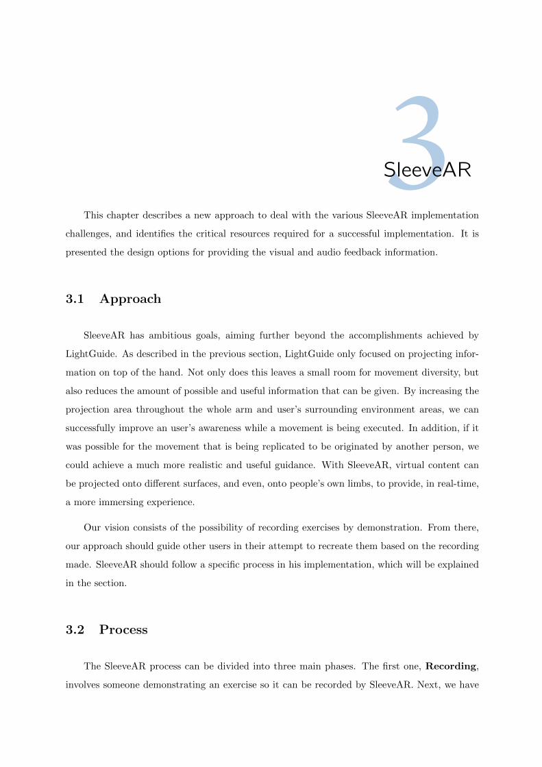
3.1 SleeveAR addresses new active projection-based strategies for providing user feed-
back during rehabilitation exercises. a) Initial position. b) Mid-performance. c)
Sleeve Feedback. d) Performance review. . . . . . . . . . . . . . . . . . . . . . . . 22
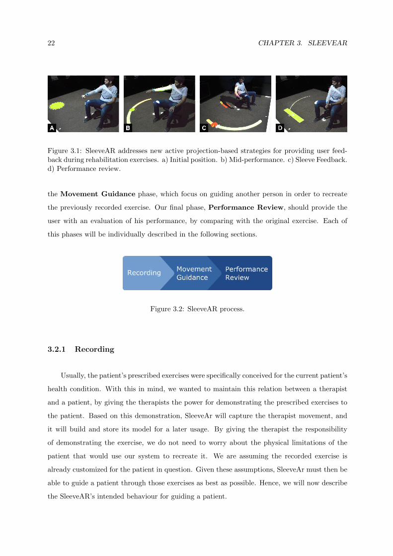
3.2 SleeveAR process. . . . . . . . . . . . . . . . . . . . . . . . . . . . . . . . . . . . 22
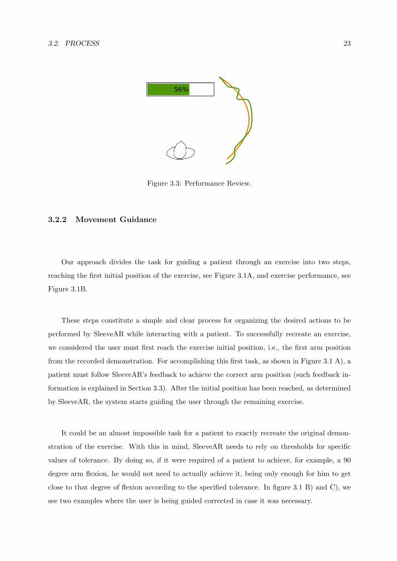
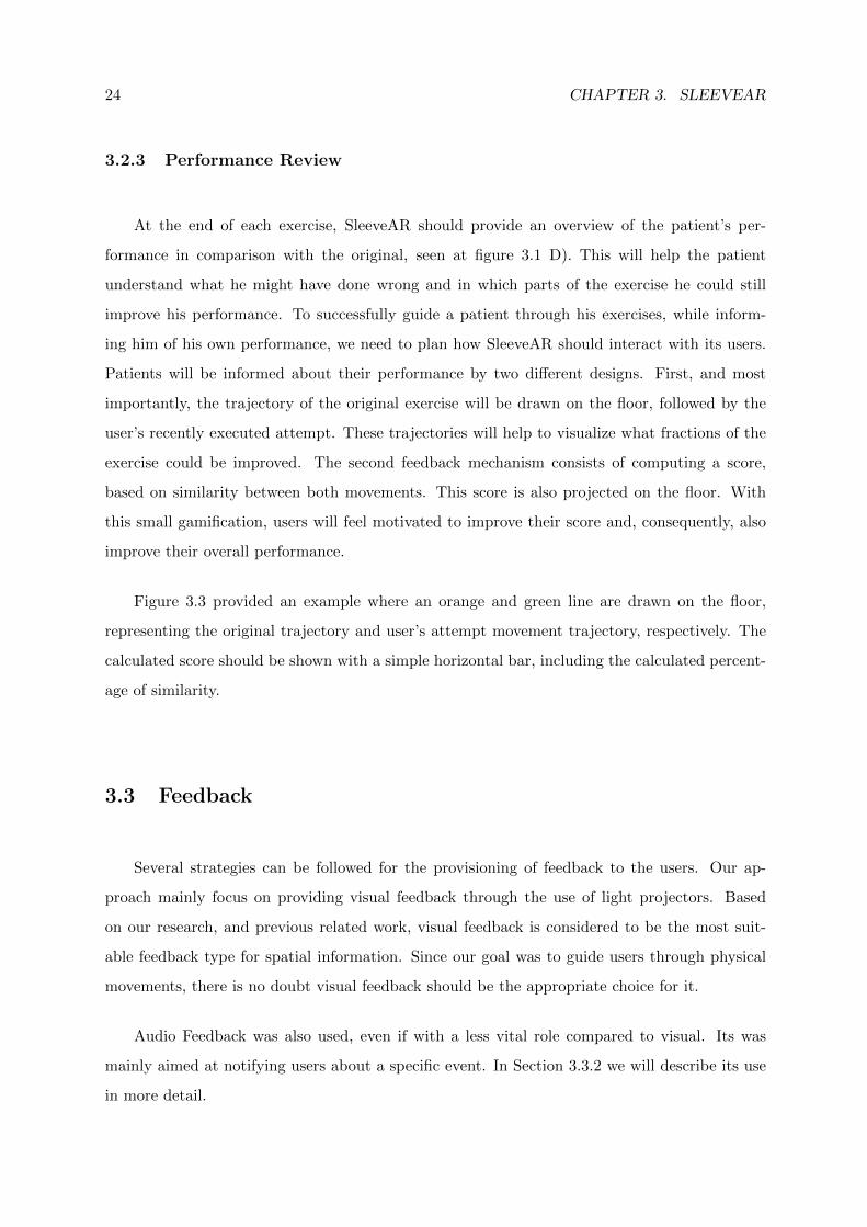
3.3 Performance Review. . . . . . . . . . . . . . . . . . . . . . . . . . . . . . . . . . . 23
3.4 Elbow Angle Definition. . . . . . . . . . . . . . . . . . . . . . . . . . . . . . . . . 25
3.5 Forearm Visual Feedback. . . . . . . . . . . . . . . . . . . . . . . . . . . . . . . . 25
3.6 Arm Elevation and Depression. . . . . . . . . . . . . . . . . . . . . . . . . . . . . 26
3.7 Arm Abduction and Adduction. . . . . . . . . . . . . . . . . . . . . . . . . . . . . 26
3.8 Upper Arm Visual Feedback. . . . . . . . . . . . . . . . . . . . . . . . . . . . . . 27
3.9 Dotted circle possible directions. . . . . . . . . . . . . . . . . . . . . . . . . . . . 27
3.10 Full Arm Visual Feedback. . . . . . . . . . . . . . . . . . . . . . . . . . . . . . . . 28
3.11 Movement Visual Feedback. . . . . . . . . . . . . . . . . . . . . . . . . . . . . . . 28
4.1 SleeveAR Architecture. . . . . . . . . . . . . . . . . . . . . . . . . . . . . . . . . 32
4.2 Work Laboratory. . . . . . . . . . . . . . . . . . . . . . . . . . . . . . . . . . . . . 34
v

4.3 Light Projector. . . . . . . . . . . . . . . . . . . . . . . . . . . . . . . . . . . . . . 34
4.4 Single Optitrack Camera. . . . . . . . . . . . . . . . . . . . . . . . . . . . . . . . 34
4.5 Single Tracking Marker. . . . . . . . . . . . . . . . . . . . . . . . . . . . . . . . . 35
4.6 Marker Combination. . . . . . . . . . . . . . . . . . . . . . . . . . . . . . . . . . . 35
4.7 Markers location on arm. . . . . . . . . . . . . . . . . . . . . . . . . . . . . . . . 35
4.8 Sleeve used for tracking. . . . . . . . . . . . . . . . . . . . . . . . . . . . . . . . . 36
4.9 Projection cube example. . . . . . . . . . . . . . . . . . . . . . . . . . . . . . . . 37
4.10 Projected circle offset. . . . . . . . . . . . . . . . . . . . . . . . . . . . . . . . . . 37
4.11 Projected Screen to Projected Area conversion. . . . . . . . . . . . . . . . . . . . 38
4.12 Cube Shadow Side-view. . . . . . . . . . . . . . . . . . . . . . . . . . . . . . . . . 38
4.13 Recording UI. . . . . . . . . . . . . . . . . . . . . . . . . . . . . . . . . . . . . . . 39
5.1 DTW comparison between SleeveAR and observing video. . . . . . . . . . . . . . 49
5.2 DTW value variation with each repetition using SleeveAR. . . . . . . . . . . . . 50
vi

List of Tables
2.1 Feature comparison with our approach . . . . . . . . . . . . . . . . . . . . . . . . 19
5.1 SleeveAR evaluation stages . . . . . . . . . . . . . . . . . . . . . . . . . . . . . . 43
5.2 Arm movements in exercises. . . . . . . . . . . . . . . . . . . . . . . . . . . . . . 45
5.3 Questionnaire results . . . . . . . . . . . . . . . . . . . . . . . . . . . . . . . . . . 46
5.4 Widgets Questionnaire . . . . . . . . . . . . . . . . . . . . . . . . . . . . . . . . . 47
5.5 Average DTW from all attempts. . . . . . . . . . . . . . . . . . . . . . . . . . . . 49
5.6 T-Student Test for all exercises. SleeveAR(S), Video(V) . . . . . . . . . . . . . . 50
A.1 T-Student Test of DTW vs Video Observation full table . . . . . . . . . . . . . . 62
B.1 Answers regarding video observation . . . . . . . . . . . . . . . . . . . . . . . . . 77
B.2 Answers regarding SleeveAR . . . . . . . . . . . . . . . . . . . . . . . . . . . . . 77
vii

viii

Acronyms
AR Augmented Reality
PT Physical Therapist
RS Rehabilitation System
KP Knowledge of Performance
KR Knowledge of Results
DTW Dynamic Time Warping
FS Feedback Service
ES Exercise Service
PP Physical Position
VP Virtual Position
PrP Projection Position
1

2
1Introduction1.1 Motivation
Even though physical therapy holds a great part of a injured person’s rehabilitation, it
also requires effort from the patient to achieve a full recovery. In fact, the patient holds great
responsibility in each therapy session. He must be ready to learn about his condition and what
types of therapeutic exercises to do and how to perform them whenever not being supervised
by a therapist (e.g., whenever performing exercises at home). To be able to exercise alone, a
patient must be taught about his body and body movements, i.e., he must gain body awareness.
A person with an acceptable body awareness has a better knowledge of his body and how to
correctly move it when doing exercises or other tasks that involve physical movement. Therefore,
a person is able to improve the overall quality of a given movement and to diminish unnecessary
muscle tension, by being able to use just the muscles required to accomplish a given task [2].
With relatively low body awareness, it becomes hard for a patient to perform well alone and
may end up hurting himself. Consequently, to help people with low awareness execute prescribed
tasks, it is necessary for them to receive real-time feedback. This feedback is usually given by
a professional, but without their presence, it would be desirable for people to receive similar
feedback from other sources to maintain a certain quality in the task execution.
Augmented Reality (AR) is a technique used to impose digital content on top of the physical
world, giving the user a different perception on the subject in which AR is being applied. This
can manipulate the meaning or increase the amount of information available of the subject being
augmented.
AR could be a possible solution to overpass the lack of clear feedback sources when no
Physical Therapist (PT) is present. It holds great potential in the field of rehabilitation and
there are already a variety of tools available to help with the development process of Augmented
Reality applications that interact with the body [3].
4 CHAPTER 1. INTRODUCTION
If combined with a carefully designed form of feedback for the patient, AR can be of great
use in the rehabilitation of a person [4]. The whole idea is to give more information to a
person so that he can more easily execute the assigned task. This feedback is usually given by a
therapist while enduring physical therapy, For unsupervised exercises, a different approach must
be followed on the types of feedback used, making sure the therapy goals are achieved and the
patient correctly performs the assigned exercises. A possible approach is to take advantage of
senses by using augmented reality feedback that facilitates the way a patient gathers feedback
information during exercise execution. Studies have already shown that the usage of augmented
reality feedback enhances the motor learning of an individual [4].
1.2 Research Statement
In this work, we introduce SleeveAR, a novel approach that provides awareness feedback
to aid and guide the patient during rehabilitation exercises. SleeveAR aims on providing the
means for patients to precisely replicate the exercises, especially prescribed for them by a health
professional. Since the rehabilitation process relies on repetition of the exercises during the
physiotherapy sessions, our approach contributes to the correct performance of the therapeutic
exercises while offering reports on the patient’s progress. Also, without rendering the role of the
therapist obsolete, our approach builds on the notion that with proper guidance, the patients
can execute rehabilitation exercises for themselves without full time supervision. With this
dissertation, we intend to validate the assumption that using interactive applications relying
on augmented reality and real-time feedback can become a better alternative to guide patients
though rehabilitation without supervision, as oppose to other sources such as video observation.
We can then highlight the research statement of this dissertation as follow:
SleeveAR can help patients exercise upper limb movements with greater
efficiency to that of an unsupervised rehabilitation.
1.3 Contributions
With the development of our SleeveAR prototype, our work provides the following contri-
butions:
1.4. PUBLICATIONS 5
• Solution for unsupervised upper-limb rehabilitation
The prototype developed in our work can help patients replicate rehabilitation exercises
even if they did not observed the exercise prior to their execution.
• Content projection on moving surfaces
We present a novel technique for projecting content on top of tracked objects. With
this technique, we are able to provide visual feedback on the actual upper-limb being
rehabilitated.
• New visual feedback designs
We created a group of minimalist visual cues to guide patients which cover the majority
of possible arm movements.
1.4 Publications
The work developed in this dissertation led to a publication evaluated by an international
panel of experts and accepted in a scientific conference. The publication is listed below.
1. Augmented Reality for Rehabilitation Using Multimodal Feedback, Joao Vieira, Maurıcio
Sousa, Artur Arsenio and Joaquim Jorge, 3rd Workshop on ICTs for improving Patients
Rehabilitation Research Techniques (REHAB 2015), October 2015.
1.5 Dissertation Outline
The remaining content of this dissertation are organised as follows. In Chapter 2 we discuss
related work that had influence on our approach, several state of the art works are presented
and a comparison between them can be found. Chapter 3 introduces our proposed solution,
SleeveAR. An approach on guiding patients through pre-recorded exercises with real-time cor-
rection feedback. Next, in Chapter 4, we present our SleeveAR implementation, describing all
the technology and development that allowed us to achieve our solution. Chapter 5 reports
the user tests conducted to evaluate our solution. And finally, in Chapter 6, we present our
conclusions and discuss our future work with SleeveAr.

6 CHAPTER 1. INTRODUCTION
2Related WorkMotor rehabilitation, or motor re-learning, is an extensive and demanding process for a
patient. For a successful recovery, the patient must be disciplined and understand that this is
a tough and painful task in which it will normally be required to move the injured area which
might cause immense pain [2]. Depending on the injury, recovery requires several physical
therapy sessions and, after finishing them, the rehabilitation might have to continue at the
patient’s own home [5].
Home rehabilitation is common among injured individuals, since attending sessions at a pro-
fessional clinic is usually not enough for a full recovery. The patient will need to add more effort
outside of the clinic and continue exercising to avoid suffering a setback on his rehabilitation [6]
or to increase his recovery speed. Hence, the patient needs to learn what exercises to do, and
how to do them correctly to prevent an aggravation of the injury [7].
There is a significant difference between rehabilitation with a PT and without him. The
therapist, while the patient attends physical therapy, helps him to fight his pain and recover from
his injury. His role is fundamental to plan the most appropriate set of exercises the patient must
perform, and to make sure they are executed correctly. Since the patient does not always has the
ability to execute alone the exercises, or not even move without an external help, the therapist
can intervene during the session and adapt his approach according to the patient’s needs [4].
However, whenever the rehabilitation exercises are done at home, without the therapist presence,
the patient might perform incorrect movements to avoid pain [7] or might not even be able to
move at all.
Repeating specific movements is a key factor in motor re-learning [8] and it should always
be a part of the rehabilitation, whether at a clinic or at home. However, this is also one of
the main causes of deteriorated rehabilitation at home. In this case, patients tend to get bored
and lose focus, due to both this repetition and the lack of a therapist presence to guide and
motivate him [2, 9, 10]. To help with this unsupervised rehabilitation work, several solutions
8 CHAPTER 2. RELATED WORK
have appeared as an alternative to the classic paper or video instructions.
Using modern technologies and counting on an increasing offer in affordable tracking devices
(e.g. Microsoft Kinect), a large diversity of applications are being developed that aim to solve
some of the difficulties in unsupervised rehabilitation [6, 11]. Several such works, focused on
rehabilitation, will be discussed in the next section.
2.1 Rehabilitation Systems
Nowadays, we can observe a wide variety of rehabilitation systems which can help improve
the recovery of a patient. Many of them have different rehabilitation goals and focus on specific
injuries, e.g., stroke [6, 12], or limbs rehabilitation [13–15].
The use of these systems can have a great influence in a patient’s rehabilitation outside of
a clinic. Not only it allows to maintain a certain quality on the execution of exercises, but also
enables the patient to exercise in a comfortable environment, his home, which makes it easier
to stimulate and motivate him during the whole process [6].
As it has been said previously, a patient’s rehabilitation is related to three concepts: repe-
tition, feedback and motivation [8]. Hence, the development of a Rehabilitation System (RS)
should always be influenced by these three ideas and how to approach them.
The repetitive nature of rehabilitation exercises can quickly become boring for a patient [10,
14, 16], therefore, there is a need for turning these exercises into something less tedious. When
dealing with repetitive exercises, the main goal should be divided into several sub-goals. This
way the patient keeps achieving incremental success through each repetition. Furthermore,
compared to the approach where success is only achieved after finishing the whole task [8], he
also increases his motivation.
For a patient to be informed about his execution, the feedback provided can be given in two
different ways. During the execution (concurrent feedback) or at the end (terminal feedback) [4].
The concurrent feedback is given in real-time with the purpose of offering correction or guidance,
it allows the patient to have Knowledge of Performance (KP). On the other hand, terminal
feedback only allows the patient to know if he succeeded after fully executing the task, giving
him Knowledge of Results (KR) [8, 12].
2.1. REHABILITATION SYSTEMS 9
Studies have shown a difficulty in obtaining a flawless formula when it comes to relating KP
and KR. On one hand, KP helps to accelerate the learning process of the exercise by correcting
the patient in real-time. On the other hand, prolonged KP can create a dependency on the
feedback, interfering with the learning process. Therefore, Sigrist [4] states that KP should be
reduced as the exercise keeps advancing, gradually giving more emphasis to KR in order to
stimulate the autonomy of the patient.
Gama et al. [3] developed a rehabilitation system in which the user position was tracked
using a Microsoft Kinect. In this system, the user would see himself on the screen with overlaying
targets that represented the desired position. If a incorrect posture was detected (shoulders not
aligned or arm not fully stretched) he would be notified in real-time with visual messages. White
arrows on the screen were also used as visual cues to guide the patient’s arm to the target. For
each repetition, points were added to a score, depending on how well the user performed.
Another work [15] focused on rehabilitating stroke victims which normally end up with one
of the arms extremely debilitated. In this case, the main focus was to motivate the patient to
move his injured arm. Even with a small range of motion, it is important for the patient to move
it in order to improve the recovery. The patient would see a virtual arm overlaying his injured
arm, which would simulate a normal arm movement. The virtual arm position was calculated
based on a few control points around the patients shoulder and face. The results shown an
enhancement of the shoulder range of motion in all the test subjects.
Also focused on stroke victims, Sadihov et al. [13] proposed a system which intended to
aid in the development of rehabilitation exercises with an immersive virtual environment. In
this case, using a haptic glove with vibration capabilities. Three virtual games were developed
where the user could interact with his hand. The vibrating motors on the glove were activated
according to what happened in the game. For example, in one of the games, the user had to
hit the incoming meteors with his hands to protect a village and every time one meteor collided
with the avatar’s hand, the haptic glove would also vibrate. This enabled patients to feel more
connected with the game and thus become more motivated to exercise their debilitated limb.
Due to improving motivation and diminishing boredom while rehabilitating, using serious
games has been a trend in the latest years as we can see for the several research published around
the theme [6,14,17–19].
Tang et al. [7] developed Physio@Home, a guidance system to help patients execute move-
10 CHAPTER 2. RELATED WORK
ments by following guidelines. The patient would see himself on a mirror and, on top of the
reflection, visual cues that indicated the direction to which the arm should move. The exercises
were pre-recorded by another person and then replicated by the patient. If the patient started
moving in the wrong direction, a red stick figure resembling the user’s arm would appear in the
nearest arm position where he should be. Even though a error metric was developed to compare
pre-recorded exercises with user’s attempt, in nowhere was stated these metric were provided
to the user. Therefore, Physio@Home only provided feedback during the performance and not
after.
Most approaches usually rely on Augmented Reality technology, enhancing our perception
of the real world by adding information or manipulating our surroundings.
2.2 Augmented Reality
Nowadays, Augmented Reality applications are being developed for several fields such as
entertainment, games, military training and medical procedures [10,20]. It is rather hard to list
all the possibilities of augmented reality when its limit can only be imposed by one’s creativity (if
we ignore technological limits). Its use can, for example, allow a surgeon to monitor a patient’s
heartbeat and temperature in real time, or even help a military jet pilot to see targets info in
his visor while flying.
In the rehabilitation field, AR has been increasingly the target of research works. The
possibility of creating interactive and immersive environments allowed to solve some of the
difficulties of classic rehabilitation.
For example, a PT could have a better judgment over a patient’s condition if he had access
to the patient’s real time data regarding body posture, joints angles or movements in general,
thus helping him to better evaluate the patient’s condition. Without augmented information,
this type of information could only be obtained through naked eye estimates or by using regular
video recordings.
A common approach in this field is to use augmented reality mirrors. This is inspired by the
need for a patient to be able to see his body while learning and executing movements, mainly to
help with spatial awareness. We can often see mirrors placed in physical therapy clinics for this
reason and, therefore, augmented reality mirrors can be considered an ”evolution” of the classic
2.2. AUGMENTED REALITY 11
mirror. But not only in rehabilitation can AR mirrors be useful: we can observe the presence
of mirrors in any activity that requires movement learning, like dancing or martial arts.
Next, we present some examples where augmented reality mirrors were used.
2.2.1 Augmented Reality Mirrors
Mirrors allow a person to have visual feedback of his body. It enhances the spatial awareness
which is useful for motor learning activities.
The concept of an AR mirror does not necessarily require an actual physical mirror to be
implemented. Its functionality can be easily simulated by a virtual mirror which consists in
capturing images with a camera and projecting them in real-time on a screen facing the user,
giving him the perception of a real mirror.
Nevertheless, there has been implementations of AR in actual physical mirrors [21]. This was
achieved by creating a mirror with a partially reflective layer facing the user and a diffuse layer
in the back. The reflective layer maintained a mirror natural reflection while a light-projector
projected images onto the diffuse layer. The result was a mixture of the user’s reflection with
virtual images.
Virtual mirrors could be considered an easier alternative to implement than the one used
above. By allowing any screen to turn into a mirror with the use of a color camera, it is normal
that this seems to be the most common approach.
AR makes it possible to add more capabilities to the classic mirror. In a visual feedback
perspective, we can generate virtual images on top of the reflection (for instance, for guid-
ing purposes). There has been already applications that make use of AR mirrors to guide a
user, whether it be for rehabilitation [7, 15, 22] or for other types of interaction not focused on
rehabilitation [23,24].
Although AR mirrors have proven to be useful for visual feedback, there are some limita-
tions. An obvious limitation of this virtual alternative is the “reflection“ dependency on the
camera direction, so that if a user looks at the screen from a different direction other than
directly forward, the reflection would not be correct. The lack of depth perception means that
3-dimensional movements are more difficult to be guided by virtual images on a flat screen. We
12 CHAPTER 2. RELATED WORK
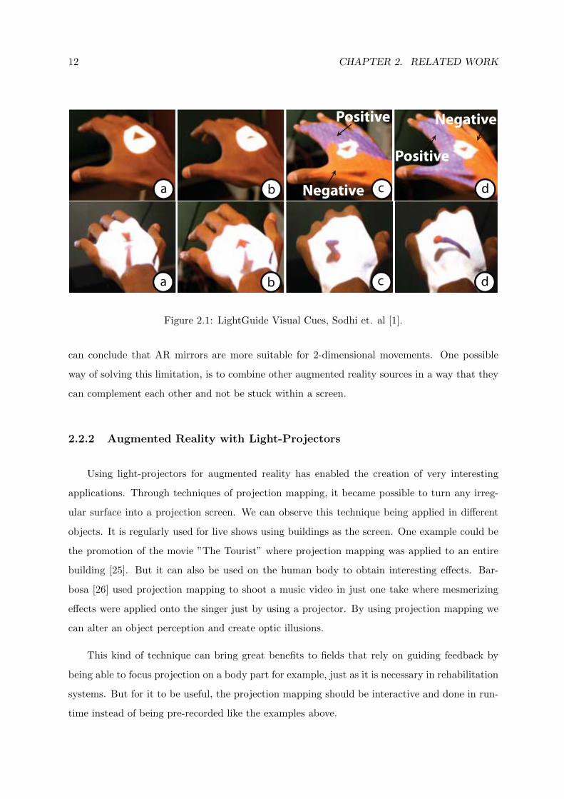
Figure 2.1: LightGuide Visual Cues, Sodhi et. al [1].
can conclude that AR mirrors are more suitable for 2-dimensional movements. One possible
way of solving this limitation, is to combine other augmented reality sources in a way that they
can complement each other and not be stuck within a screen.
2.2.2 Augmented Reality with Light-Projectors
Using light-projectors for augmented reality has enabled the creation of very interesting
applications. Through techniques of projection mapping, it became possible to turn any irreg-
ular surface into a projection screen. We can observe this technique being applied in different
objects. It is regularly used for live shows using buildings as the screen. One example could be
the promotion of the movie ”The Tourist” where projection mapping was applied to an entire
building [25]. But it can also be used on the human body to obtain interesting effects. Bar-
bosa [26] used projection mapping to shoot a music video in just one take where mesmerizing
effects were applied onto the singer just by using a projector. By using projection mapping we
can alter an object perception and create optic illusions.
This kind of technique can bring great benefits to fields that rely on guiding feedback by
being able to focus projection on a body part for example, just as it is necessary in rehabilitation
systems. But for it to be useful, the projection mapping should be interactive and done in run-
time instead of being pre-recorded like the examples above.
2.3. TRACKING TECHNIQUES 13
LightGuide [1], explored the use of projection mapping in a innovative way. The projection
was made onto the user, using his body as a projection screen. Real-time visual cues were pro-
jected onto the user’s hand in order to guide him through the desired movement. By projecting
the information in the body part being moved, the user could keep a high level of concentration
without being distracted by external factors. As we can in the examples shown in Figure 2.1,
different types of visual cues were developed, having in mind movements that demanded degrees
of freedom over 3 dimensions. For each dimension a different design was planned so that the
user could understand clearly to what direction should his hand move.
To apply real-time projection mapping onto a moving body part, its position must be known
at all time to make sure the light projector is illuminating the correct position. For this, motion
tracking devices are used which enable to record the movement of, in this case, a person.
2.3 Tracking Techniques
Tracking devices have enabled the development of more immersive interactive applications.
Whether it be for entertainment or more serious matters, the possibility of interacting with an
interface without using any kind of handheld devices can greatly enhance a user experience.
Nowadays it is possible to obtain affordable tracking devices such as Microsoft’s Kinect,
which can provide full skeleton tracking without the use of any kind of special equipment. As
opposed to more professional solutions that require special suits with markers, but provide a
more accurate tracking. Even so, studies have shown that Kinect has an acceptable accuracy in
comparison with other motion tracking alternatives and can be considered a valuable option for
its low price and easy portability [27,28].
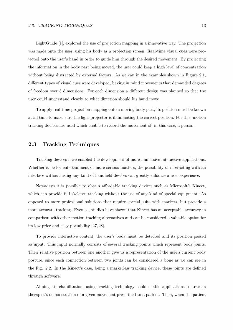
To provide interactive content, the user’s body must be detected and its position passed
as input. This input normally consists of several tracking points which represent body joints.
Their relative position between one another give us a representation of the user’s current body
posture, since each connection between two joints can be considered a bone as we can see in
the Fig. 2.2. In the Kinect’s case, being a markerless tracking device, these joints are defined
through software.
Aiming at rehabilitation, using tracking technology could enable applications to track a
therapist’s demonstration of a given movement prescribed to a patient. Then, when the patient
14 CHAPTER 2. RELATED WORK
Figure 2.2: Joints position from Kinect
performed it, his movement could also be tracked and compared to the therapist’s demonstration
to detect possible errors. For this to be possible, several factors have to be taken into account
like the possible physical differences between both. If we were to make a “blind“ comparison
between both skeletons, the results would not be accurate.
Two comparison methods that can be used to address the aforementioned problem are
described hereafter.
2.3.1 Skeleton Comparison Methods
In order to facilitate the description of the following methods, we will consider two given
skeletons named SK1 and SK2, both with the same number of defined joints and where SK2
wants to mimic SK1’s pose.
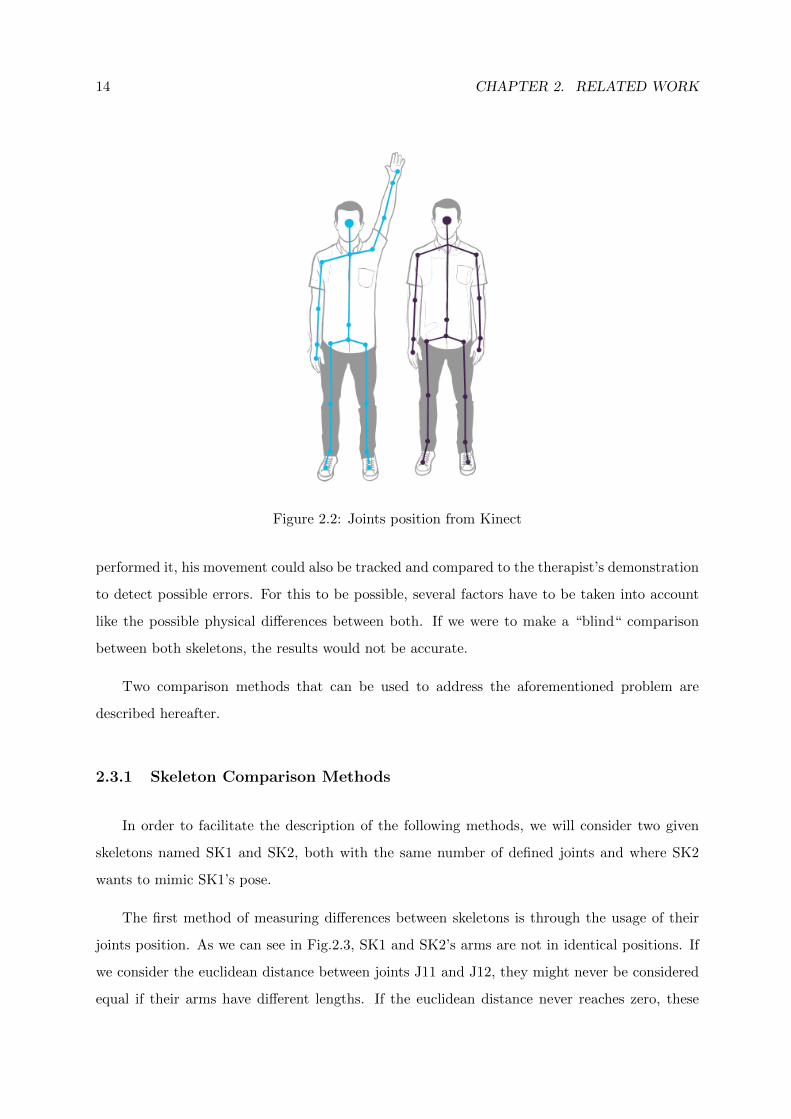
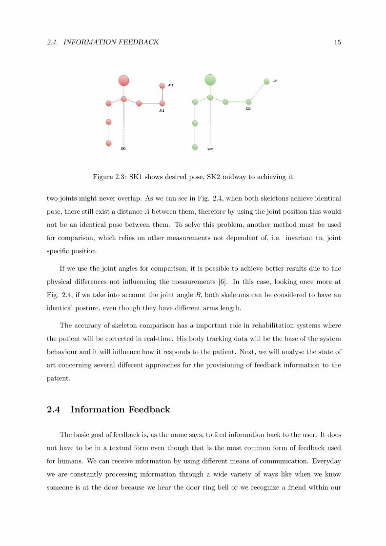
The first method of measuring differences between skeletons is through the usage of their
joints position. As we can see in Fig.2.3, SK1 and SK2’s arms are not in identical positions. If
we consider the euclidean distance between joints J11 and J12, they might never be considered
equal if their arms have different lengths. If the euclidean distance never reaches zero, these
2.4. INFORMATION FEEDBACK 15
Figure 2.3: SK1 shows desired pose, SK2 midway to achieving it.
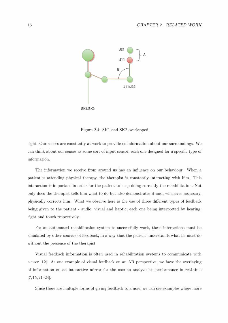
two joints might never overlap. As we can see in Fig. 2.4, when both skeletons achieve identical
pose, there still exist a distance A between them, therefore by using the joint position this would
not be an identical pose between them. To solve this problem, another method must be used
for comparison, which relies on other measurements not dependent of, i.e. invariant to, joint
specific position.
If we use the joint angles for comparison, it is possible to achieve better results due to the
physical differences not influencing the measurements [6]. In this case, looking once more at
Fig. 2.4, if we take into account the joint angle B, both skeletons can be considered to have an
identical posture, even though they have different arms length.
The accuracy of skeleton comparison has a important role in rehabilitation systems where
the patient will be corrected in real-time. His body tracking data will be the base of the system
behaviour and it will influence how it responds to the patient. Next, we will analyse the state of
art concerning several different approaches for the provisioning of feedback information to the
patient.
2.4 Information Feedback
The basic goal of feedback is, as the name says, to feed information back to the user. It does
not have to be in a textual form even though that is the most common form of feedback used
for humans. We can receive information by using different means of communication. Everyday
we are constantly processing information through a wide variety of ways like when we know
someone is at the door because we hear the door ring bell or we recognize a friend within our
16 CHAPTER 2. RELATED WORK
Figure 2.4: SK1 and SK2 overlapped
sight. Our senses are constantly at work to provide us information about our surroundings. We
can think about our senses as some sort of input sensor, each one designed for a specific type of
information.
The information we receive from around us has an influence on our behaviour. When a
patient is attending physical therapy, the therapist is constantly interacting with him. This
interaction is important in order for the patient to keep doing correctly the rehabilitation. Not
only does the therapist tells him what to do but also demonstrates it and, whenever necessary,
physically corrects him. What we observe here is the use of three different types of feedback
being given to the patient - audio, visual and haptic, each one being interpreted by hearing,
sight and touch respectively.
For an automated rehabilitation system to successfully work, these interactions must be
simulated by other sources of feedback, in a way that the patient understands what he must do
without the presence of the therapist.
Visual feedback information is often used in rehabilitation systems to communicate with
a user [12]. As one example of visual feedback on an AR perspective, we have the overlaying
of information on an interactive mirror for the user to analyze his performance in real-time
[7, 15,21–24].
Since there are multiple forms of giving feedback to a user, we can see examples where more
2.4. INFORMATION FEEDBACK 17
than one are used at the same time. Combining forms of feedback can provide better under-
standing of the tasks to a user by minimizing the amount of information given in a visual form
and, instead, distribute it. But if not designed with caution, a system can end up overloading
the user with too much information at the same time.
2.4.1 Feedback Applications
Sigrist et al. [4] suggests that different types of feedback can complement each other and
enhance the user comprehension. Alhamid et al. [23] introduced an interface between a user and
biofeedback sensors (sensors that are able to measure physiological functions). Even though it
is not aimed for rehabilitation, his approach on user interaction can be analyzed. Through this
interface, the user was able to access data about his body and health thanks to the measurements
made by the biofeedback sensors. This system was prepared to interact with the user using
multiple response interfaces, each one intended for specific purposes. The visual interface relied
on a projector that showed important messages and results from the biofeedback measurements.
In the other hand, the audio interface was responsible for playing different kinds of music through
speakers. The music was selected depending on the user’s current state. For example, if high
levels of stress are detected, calming music would be played to help the user relax.
One of the most common approaches on visual feedback is the augmented mirror approach
already discussed. Its common use is justified by the fact that even without overlaying virtual
images, it enables the user to have a spatial awareness of his own body. But since a simple
reflection does not provide guidance, we could observe several examples of augmented feedback
being applied to the mirror. Physio@Home, the work of Tang et al. [7], explored two different
designs for visual guidance on a mirror aimed at upper-limbs movement. Their first iteration
consisted of virtual arrows that pointed at the targeted position for the user’s hand. The second
provided a trace of tubes placed along a path which represented the complete movement to be
performed by the user’s arm. In both cases it was detected some difficulty in depth perception.
This kind of visual cues has proven not to be suitable for exercises where the user had to move
his arm towards the camera or when he had to contract it.
Anderson et al. [21] tried to provide a more detailed visual feedback by using a full virtual
skeleton placed over the user reflection. In this case the goal was to mimic the skeleton’s pose
and hold it for a specific time. To diminish the lack of depth perception, a second tracker was
18 CHAPTER 2. RELATED WORK
placed on the user’s side. Every time the system detected a large error on the z-axis, a window
would appear with a side-view of both the virtual and user’s skeleton for him to be corrected.
Unlike the previous approach, LightGuide [1] does not rely on interactive mirrors or screens
to apply its visual feedback. By using a depth-sensor camera and a light projector, they were able
to project information on the user’s hand. This approach was able to guide the hand through
a defined movement by projecting visual cues. All the information projected on the hand was
being updated in real-time influenced by the current position given by the tracking device. The
visual cues varied according to the desired direction of the movement. If the current movement
only required back and forward motion, only one dimension was being used. Therefore, the
visual cue would only inform the user where to move his hand in the z axis through a little
arrow pointing to the correct position. Two dimensional movements would combine the first
visual cue by virtually painting the remaining of the hand with a color pattern. The portion
of the hand closer to the desired position, would be painted with a different color than the
remaining portion. They concluded that by using LightGuide, most of the users could better
execute a certain movement than if they were following video instructions.
2.5 Related Work Overview
After analyzing several examples of feedback approaches, it is possible to make some con-
clusions about their usefulness, whether it be rehabilitation-oriented or not. Indeed, each of
the three types of feedback observed, namely visual, audio and haptic, have shown to be more
suitable for different purposes. Visual feedback appears to be normally used in regard to spatial
information, due to the perception of space being the most precise when using the sense of sight.
For this reason, the best option to guide a patient through movements seems to be by using
visual guidance. But it is important to note that visual feedback still is a rather broad concept,
therefore we could observe different takes on the whole subject of visual guidance.
The AR mirror, discussed at Section 2.2.1, is the most common solution to provide visual
feedback, given that it can add information to the already present mirror reflection. Even
though a problem seems to persist throughout the several examples, namely the lack of depth
perception. But other approaches might have a chance of solving this problem if one tries to
combine them both.
2.6. SUMMARY 19
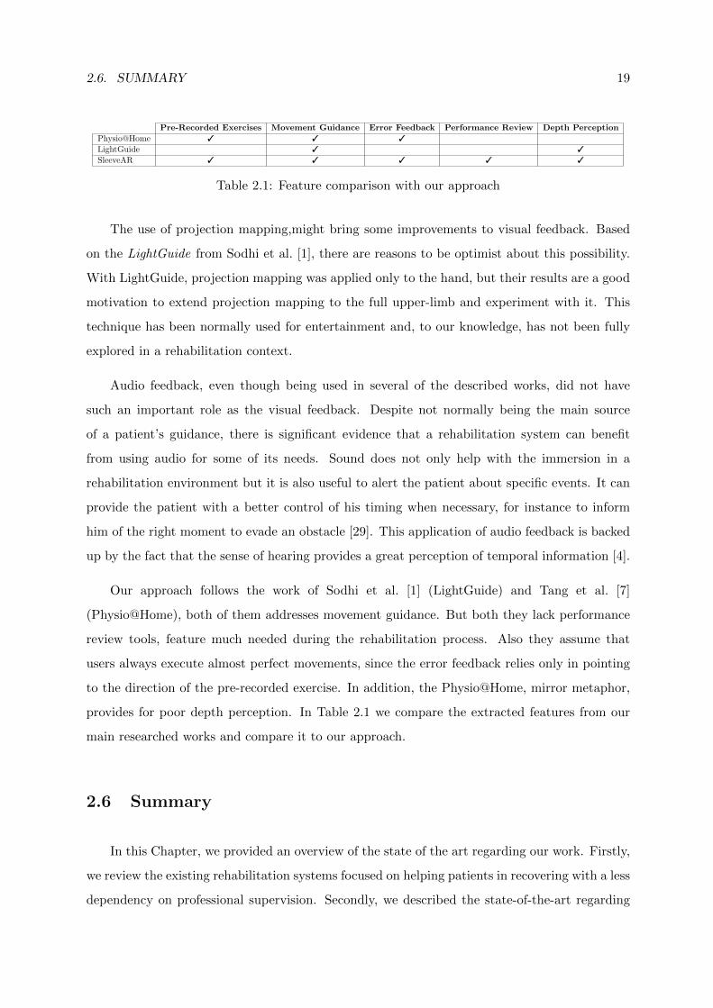
Pre-Recorded Exercises Movement Guidance Error Feedback Performance Review Depth Perception
Physio@Home 3 3 3
LightGuide 3 3
SleeveAR 3 3 3 3 3
Table 2.1: Feature comparison with our approach
The use of projection mapping,might bring some improvements to visual feedback. Based
on the LightGuide from Sodhi et al. [1], there are reasons to be optimist about this possibility.
With LightGuide, projection mapping was applied only to the hand, but their results are a good
motivation to extend projection mapping to the full upper-limb and experiment with it. This
technique has been normally used for entertainment and, to our knowledge, has not been fully
explored in a rehabilitation context.
Audio feedback, even though being used in several of the described works, did not have
such an important role as the visual feedback. Despite not normally being the main source
of a patient’s guidance, there is significant evidence that a rehabilitation system can benefit
from using audio for some of its needs. Sound does not only help with the immersion in a
rehabilitation environment but it is also useful to alert the patient about specific events. It can
provide the patient with a better control of his timing when necessary, for instance to inform
him of the right moment to evade an obstacle [29]. This application of audio feedback is backed
up by the fact that the sense of hearing provides a great perception of temporal information [4].
Our approach follows the work of Sodhi et al. [1] (LightGuide) and Tang et al. [7]
(Physio@Home), both of them addresses movement guidance. But both they lack performance
review tools, feature much needed during the rehabilitation process. Also they assume that
users always execute almost perfect movements, since the error feedback relies only in pointing
to the direction of the pre-recorded exercise. In addition, the Physio@Home, mirror metaphor,
provides for poor depth perception. In Table 2.1 we compare the extracted features from our
main researched works and compare it to our approach.
2.6 Summary
In this Chapter, we provided an overview of the state of the art regarding our work. Firstly,
we review the existing rehabilitation systems focused on helping patients in recovering with a less
dependency on professional supervision. Secondly, we described the state-of-the-art regarding

20 CHAPTER 2. RELATED WORK
the use of Augmented Reality in a rehabilitation context. Also, we described some interesting
works that, even tought not aimed for rehabilitation, could be applied in this same context.
Thirdly, we provided some insight related to tracking techniques and possible obstacles in com-
paring different subjects due to physical differences. Fourthly, we focused on different ways of
providing feedback to users and describe some works that used real-time feedback to inform
users about their activity. Finally, we make a features comparison between, what we considered,
the main presented works and our approach. Following this chapter, we describe our proposed
approach.
3SleeveARThis chapter describes a new approach to deal with the various SleeveAR implementation
challenges, and identifies the critical resources required for a successful implementation. It is
presented the design options for providing the visual and audio feedback information.
3.1 Approach
SleeveAR has ambitious goals, aiming further beyond the accomplishments achieved by
LightGuide. As described in the previous section, LightGuide only focused on projecting infor-
mation on top of the hand. Not only does this leaves a small room for movement diversity, but
also reduces the amount of possible and useful information that can be given. By increasing the
projection area throughout the whole arm and user’s surrounding environment areas, we can
successfully improve an user’s awareness while a movement is being executed. In addition, if it
was possible for the movement that is being replicated to be originated by another person, we
could achieve a much more realistic and useful guidance. With SleeveAR, virtual content can
be projected onto different surfaces, and even, onto people’s own limbs, to provide, in real-time,
a more immersing experience.
Our vision consists of the possibility of recording exercises by demonstration. From there,
our approach should guide other users in their attempt to recreate them based on the recording
made. SleeveAR should follow a specific process in his implementation, which will be explained
in the section.
3.2 Process
The SleeveAR process can be divided into three main phases. The first one, Recording,
involves someone demonstrating an exercise so it can be recorded by SleeveAR. Next, we have
22 CHAPTER 3. SLEEVEAR
Figure 3.1: SleeveAR addresses new active projection-based strategies for providing user feed-back during rehabilitation exercises. a) Initial position. b) Mid-performance. c) Sleeve Feedback.d) Performance review.
the Movement Guidance phase, which focus on guiding another person in order to recreate
the previously recorded exercise. Our final phase, Performance Review, should provide the
user with an evaluation of his performance, by comparing with the original exercise. Each of
this phases will be individually described in the following sections.
Figure 3.2: SleeveAR process.
3.2.1 Recording
Usually, the patient’s prescribed exercises were specifically conceived for the current patient’s
health condition. With this in mind, we wanted to maintain this relation between a therapist
and a patient, by giving the therapists the power for demonstrating the prescribed exercises to
the patient. Based on this demonstration, SleeveAr will capture the therapist movement, and
it will build and store its model for a later usage. By giving the therapist the responsibility
of demonstrating the exercise, we do not need to worry about the physical limitations of the
patient that would use our system to recreate it. We are assuming the recorded exercise is
already customized for the patient in question. Given these assumptions, SleeveAr must then be
able to guide a patient through those exercises as best as possible. Hence, we will now describe
the SleeveAR’s intended behaviour for guiding a patient.
3.2. PROCESS 23
Figure 3.3: Performance Review.
3.2.2 Movement Guidance
Our approach divides the task for guiding a patient through an exercise into two steps,
reaching the first initial position of the exercise, see Figure 3.1A, and exercise performance, see
Figure 3.1B.
These steps constitute a simple and clear process for organizing the desired actions to be
performed by SleeveAR while interacting with a patient. To successfully recreate an exercise,
we considered the user must first reach the exercise initial position, i.e., the first arm position
from the recorded demonstration. For accomplishing this first task, as shown in Figure 3.1 A), a
patient must follow SleeveAR’s feedback to achieve the correct arm position (such feedback in-
formation is explained in Section 3.3). After the initial position has been reached, as determined
by SleeveAR, the system starts guiding the user through the remaining exercise.
It could be an almost impossible task for a patient to exactly recreate the original demon-
stration of the exercise. With this in mind, SleeveAR needs to rely on thresholds for specific
values of tolerance. By doing so, if it were required of a patient to achieve, for example, a 90
degree arm flexion, he would not need to actually achieve it, being only enough for him to get
close to that degree of flexion according to the specified tolerance. In figure 3.1 B) and C), we
see two examples where the user is being guided corrected in case it was necessary.
24 CHAPTER 3. SLEEVEAR
3.2.3 Performance Review
At the end of each exercise, SleeveAR should provide an overview of the patient’s per-
formance in comparison with the original, seen at figure 3.1 D). This will help the patient
understand what he might have done wrong and in which parts of the exercise he could still
improve his performance. To successfully guide a patient through his exercises, while inform-
ing him of his own performance, we need to plan how SleeveAR should interact with its users.
Patients will be informed about their performance by two different designs. First, and most
importantly, the trajectory of the original exercise will be drawn on the floor, followed by the
user’s recently executed attempt. These trajectories will help to visualize what fractions of the
exercise could be improved. The second feedback mechanism consists of computing a score,
based on similarity between both movements. This score is also projected on the floor. With
this small gamification, users will feel motivated to improve their score and, consequently, also
improve their overall performance.
Figure 3.3 provided an example where an orange and green line are drawn on the floor,
representing the original trajectory and user’s attempt movement trajectory, respectively. The
calculated score should be shown with a simple horizontal bar, including the calculated percent-
age of similarity.
3.3 Feedback
Several strategies can be followed for the provisioning of feedback to the users. Our ap-
proach mainly focus on providing visual feedback through the use of light projectors. Based
on our research, and previous related work, visual feedback is considered to be the most suit-
able feedback type for spatial information. Since our goal was to guide users through physical
movements, there is no doubt visual feedback should be the appropriate choice for it.
Audio Feedback was also used, even if with a less vital role compared to visual. Its was
mainly aimed at notifying users about a specific event. In Section 3.3.2 we will describe its use
in more detail.
3.3. FEEDBACK 25
Figure 3.4: Elbow Angle Definition. Figure 3.5: Forearm Visual Feedback.
3.3.1 Visual Feedback
A useful and minimalist design was targeted for the visual feedback. There were some
key points we wanted to address when designing it. First of all, the visual information had to
provide the user with a representation of his current position, while also showing the desired
position. These representations had to be done in a way the user would easily comprehend
what to do for achieving a desired position. To provide suitable feedback regarding the full arm,
we first applied a different design for each of the regions. Next, we will present our planned
visual feedback designs. Our goal with the following feedback designs was to accomplish a clear
correction of the users’ arm in the context of the several types of anatomic movements an arm
can execute. For each visual feedback described, we will refer to the corresponding anatomic
arm movement.
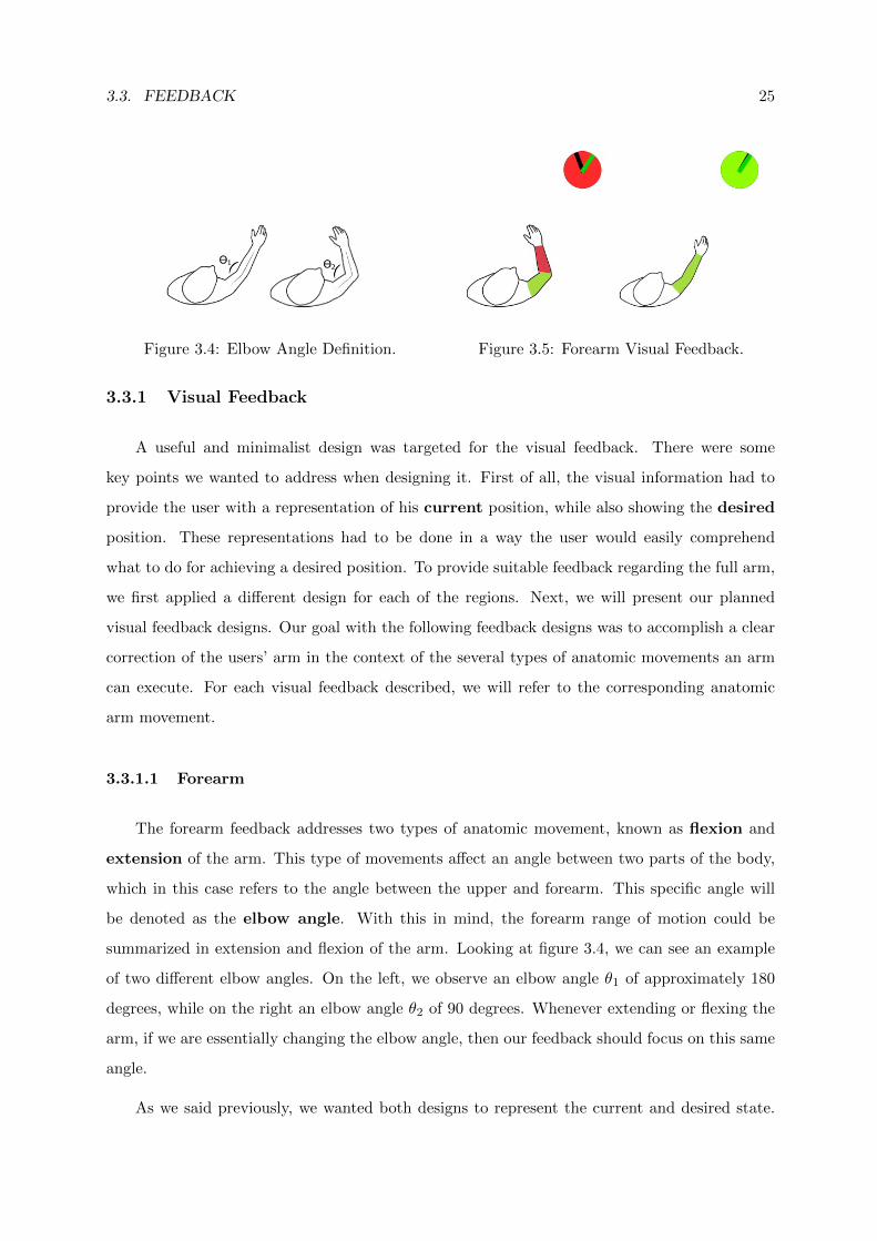
3.3.1.1 Forearm
The forearm feedback addresses two types of anatomic movement, known as flexion and
extension of the arm. This type of movements affect an angle between two parts of the body,
which in this case refers to the angle between the upper and forearm. This specific angle will
be denoted as the elbow angle. With this in mind, the forearm range of motion could be
summarized in extension and flexion of the arm. Looking at figure 3.4, we can see an example
of two different elbow angles. On the left, we observe an elbow angle θ1 of approximately 180
degrees, while on the right an elbow angle θ2 of 90 degrees. Whenever extending or flexing the
arm, if we are essentially changing the elbow angle, then our feedback should focus on this same
angle.
As we said previously, we wanted both designs to represent the current and desired state.
26 CHAPTER 3. SLEEVEAR
Figure 3.6: Arm Elevation and Depression. Figure 3.7: Arm Abduction and Adduction.
Our final design for a forearm feedback makes use of a circle with two bars, similar to a clock
with two pointers. The black bar, seen in figure 3.5, is used to represent the current state.
Whenever the user moves his forearm, this bar will move accordingly. On the other hand, the
desired forearm state is represented by the green bar. For the user to achieve this state, he needs
to move his forearm so that the black bar reaches the green bar.
Two additional features were specifically introduced into this design to extend the user’s
awareness. Depending on the distance between both bars, the circle color would fade between
red (too far from goal), and green (for close enough). In addition, if the black bar gets too far
from the desired position, rotating arrows will appear to warn the user that he is currently not
correctly positioned. Next we present the planned design for the upper arm feedback.
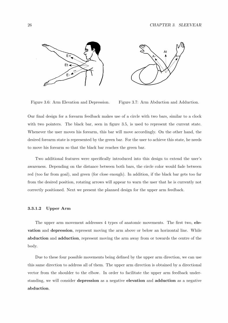
3.3.1.2 Upper Arm
The upper arm movement addresses 4 types of anatomic movements. The first two, ele-
vation and depression, represent moving the arm above or below an horizontal line. While
abduction and adduction, represent moving the arm away from or towards the centre of the
body.
Due to these four possible movements being defined by the upper arm direction, we can use
this same direction to address all of them. The upper arm direction is obtained by a directional
vector from the shoulder to the elbow. In order to facilitate the upper arm feedback under-
standing, we will consider depression as a negative elevation and adduction as a negative
abduction.
3.3. FEEDBACK 27
Figure 3.8: Upper Arm Visual Feedback. Figure 3.9: Dotted circle possible directions.
Observing the figure 3.6, we have an example where Et represents the elevation target,
while, relative to this target, the user could have higher elevation (E+) or lower elevation (E-).
While in figure 3.7, we observe an abduction target, At, and following the previous example,
higher or lower abduction A+ and A-.
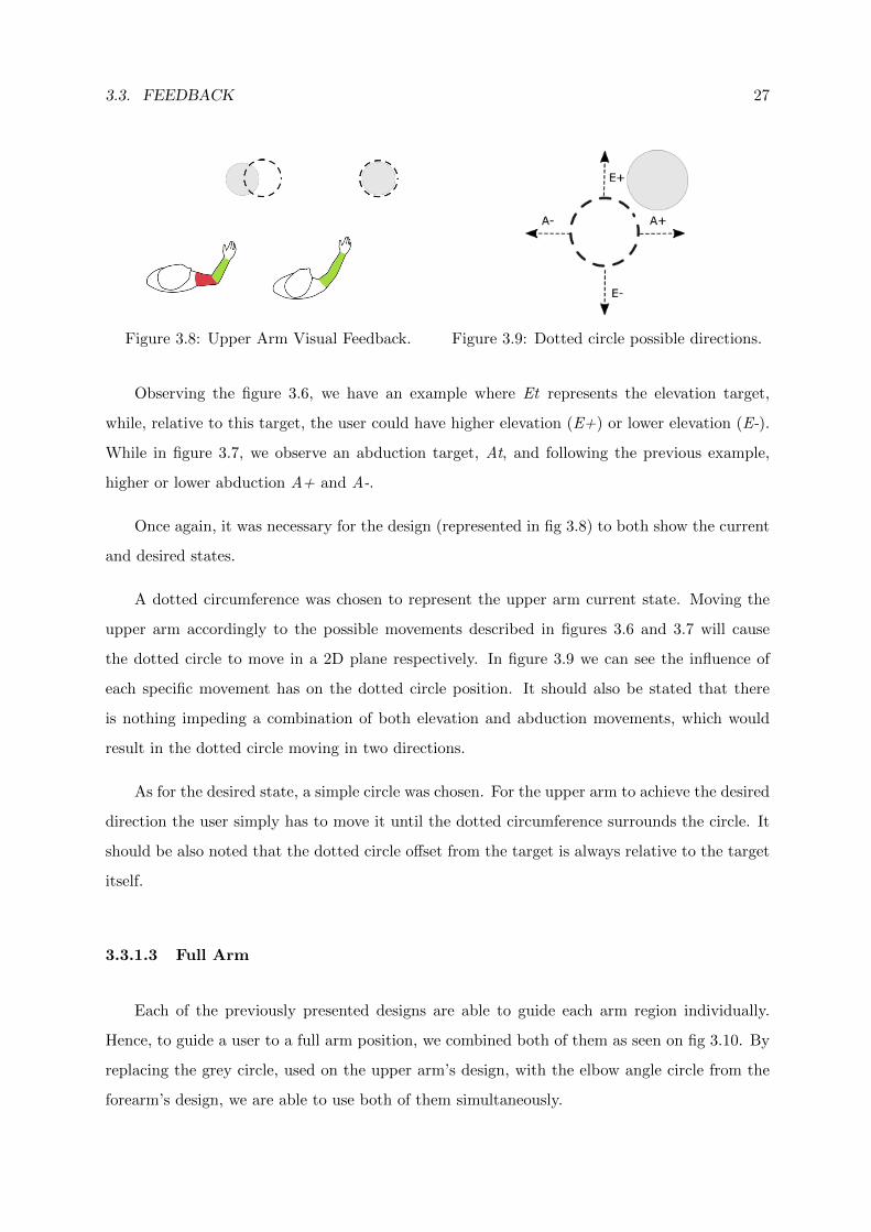
Once again, it was necessary for the design (represented in fig 3.8) to both show the current
and desired states.
A dotted circumference was chosen to represent the upper arm current state. Moving the
upper arm accordingly to the possible movements described in figures 3.6 and 3.7 will cause
the dotted circle to move in a 2D plane respectively. In figure 3.9 we can see the influence of
each specific movement has on the dotted circle position. It should also be stated that there
is nothing impeding a combination of both elevation and abduction movements, which would
result in the dotted circle moving in two directions.
As for the desired state, a simple circle was chosen. For the upper arm to achieve the desired
direction the user simply has to move it until the dotted circumference surrounds the circle. It
should be also noted that the dotted circle offset from the target is always relative to the target
itself.
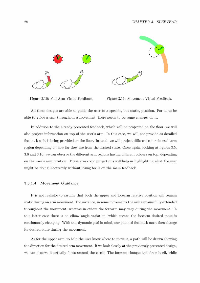
3.3.1.3 Full Arm
Each of the previously presented designs are able to guide each arm region individually.
Hence, to guide a user to a full arm position, we combined both of them as seen on fig 3.10. By
replacing the grey circle, used on the upper arm’s design, with the elbow angle circle from the
forearm’s design, we are able to use both of them simultaneously.
28 CHAPTER 3. SLEEVEAR
Figure 3.10: Full Arm Visual Feedback. Figure 3.11: Movement Visual Feedback.
All these designs are able to guide the user to a specific, but static, position. For us to be
able to guide a user throughout a movement, there needs to be some changes on it.
In addition to the already presented feedback, which will be projected on the floor, we will
also project information on top of the user’s arm. In this case, we will not provide as detailed
feedback as it is being provided on the floor. Instead, we will project different colors in each arm
region depending on how far they are from the desired state. Once again, looking at figures 3.5,
3.8 and 3.10, we can observe the different arm regions having different colours on top, depending
on the user’s arm position. These arm color projections will help in highlighting what the user
might be doing incorrectly without losing focus on the main feedback.
3.3.1.4 Movement Guidance
It is not realistic to assume that both the upper and forearm relative position will remain
static during an arm movement. For instance, in some movements the arm remains fully extended
throughout the movement, whereas in others the forearm may vary during the movement. In
this latter case there is an elbow angle variation, which means the forearm desired state is
continuously changing. With this dynamic goal in mind, our planned feedback must then change
its desired state during the movement.
As for the upper arm, to help the user know where to move it, a path will be drawn showing
the direction for the desired arm movement. If we look closely at the previously presented design,
we can observe it actually focus around the circle. The forearm changes the circle itself, while
3.4. SUMMARY 29
the upper arm controls the dotted circumference that must cover also the circle. With this in
mind, if we move this same circle through the movement path, we will be able to continuously
inform the user about the desired direction while also updating what specific elbow angle he
should have. In fig 3.11 we can see an example where the user is already in the middle of the
exercise (at the trajectory midpoint).
3.3.2 Audio
Audio feedback was found to be more suitable for timing and user notification contexts.
Hence, we planned the usage of audio for notifying our users about specific events in SleeveAR.
In the Recording phase, SleeveAR had to provide a notification when it actually starts
recording. In this case, a countdown audio clip was used to briefly prepare the user, so he could
position himself in the desired exercise initial position, before the actual recording began. An-
other notification sound was also played when the recording has stopped. As for the Movement
Guidance phase, SleeveAR notified the user whenever an exercise attempt started. From there,
the main source of feedback was provided in visual form.
3.4 Summary
In this chapter we explained SleeveAR, our approach for the presented problem. Firstly, we
introduced the three main phases of what we consider to be SleeveAR’s process. Secondly, we
present our planned visual design to be used when guiding patients through movements, while
explaining which possible arm movements are covered by each. Finally, we describe how will
audio feedback be used in our approach. The following chapter describes the set of tools devel-
oped and devices used to build our SleeveAR prototype following the requirements presented in
this chapter.

30 CHAPTER 3. SLEEVEAR
4PrototypeA SleeveAR prototype was built according to our human augmented assistance vision, and
complying with the solution requirements. The prototype had to rely on some already existing
devices to implement all planned features, namely for motion tracking and perception and actu-
ation mechanisms for the feedback sources. After describing SleeveAR testbed and architecture,
employed devices, and the setup environment, this chapter will present a description of the most
important implementation details.
4.1 Architecture
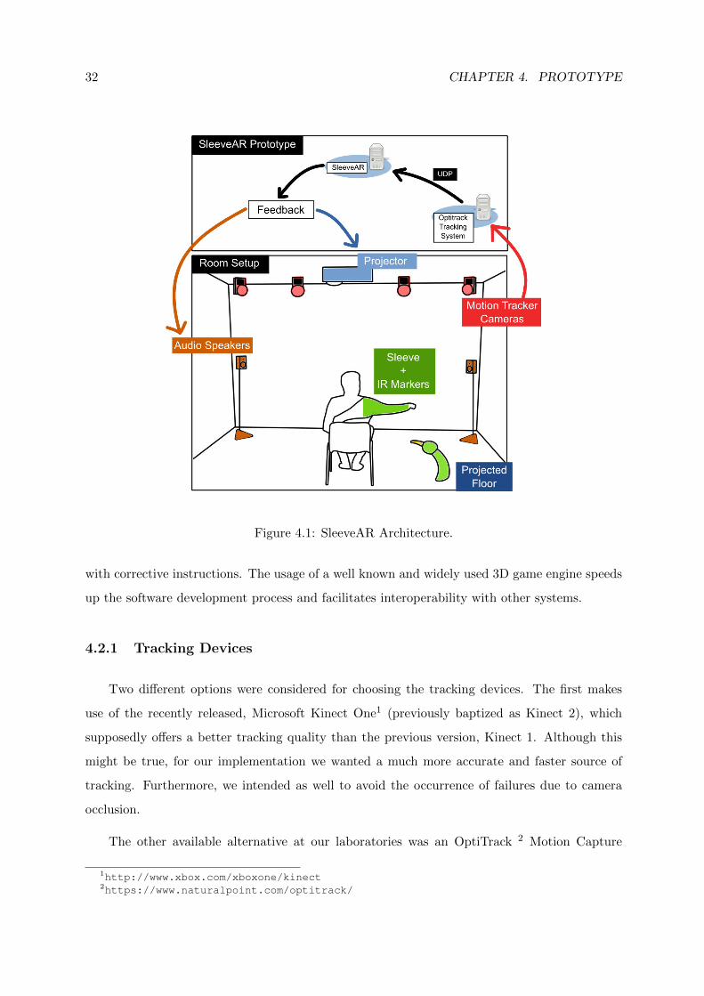
The SleeveAR architecture, which can be seen in Figure 4.1, relies on several devices for
both receiving and sending information. In terms of input, we are receiving real-time tracking
information through an UDP connection with a tracking dedicated computer. Section 4.2.1 and
4.4.1 will explain in more detail what devices were used and how did we actually were able to
track a user’s arm by using a sleeve with markers.
Given the real-time tracking information, the SleeveAR prototype will then generate user
feedback according to a specific exercise the user should attempt to execute. Such feedback was
provided by controlling speakers to deliver audio notifications and, most importantly, by making
usage of a light projector to project information both on the user’s arm and floor. Section 4.4.2
explains in detail how this projection was achieved.
4.2 Tools
The SleeveAR implementation was aided with the usage of already existing tools. Tracking
devices were employed for capturing and tracking the user movements. Actuator devices, namely
audio speakers and video projectors, were also employed as feedback devices to provide users
32 CHAPTER 4. PROTOTYPE
Figure 4.1: SleeveAR Architecture.
with corrective instructions. The usage of a well known and widely used 3D game engine speeds
up the software development process and facilitates interoperability with other systems.
4.2.1 Tracking Devices
Two different options were considered for choosing the tracking devices. The first makes
use of the recently released, Microsoft Kinect One1 (previously baptized as Kinect 2), which
supposedly offers a better tracking quality than the previous version, Kinect 1. Although this
might be true, for our implementation we wanted a much more accurate and faster source of
tracking. Furthermore, we intended as well to avoid the occurrence of failures due to camera
occlusion.
The other available alternative at our laboratories was an OptiTrack 2 Motion Capture
1http://www.xbox.com/xboxone/kinect2https://www.naturalpoint.com/optitrack/
4.2. TOOLS 33
system. This option offered us a more precise tracking, and the possibility of dealing with
occlusions due to the usage of multiple cameras scattered around the room. The downside is
the need for body markers to be carried out by a person for successfully detect him, unlike the
Kinect, which detects the human body through software algorithms.
This issue was alleviated by conceiving a comfortable and rather easy way to attach these
body markers. A description of how we used the body markers can be found in Section 4.4.1.
4.2.2 Feedback Devices
Providing effective feedback could be considered one of the foundations of this work. We
chose to provide both visual and auditory feedback, being the latter much less vital to our goals
in this implementation.
As previously described in Section 3, our planned visual feedback should be applied on
the user’s arm and floor. Hence, we relied on a light projector attached to the ceiling of our
laboratory to project all visual feedback. Details about how the light projections were able
to hit the correct places, specifically the user’s moving arm and floor, will be explained in
Section 4.4.2. Audio feedback was used for simple notifications. To provide audio, we relied on
a speaker system also available at our laboratory.
4.2.3 Software
We chose to implement our prototype with the well known Unity3D game engine3. This
engine already includes several tools that facilitate the development of augmented reality ap-
plications. We have in our possession already developed frameworks to communicate with the
available tracking devices. In addition, Unity3D uses C# as its main programming language,
which is one of the most common languages use in the game development world, and it already
offers a wide range of solutions to create visual information.
3http://www.unity3d.com
34 CHAPTER 4. PROTOTYPE
Figure 4.2: Work Laboratory. Figure 4.3: Light Projector. Figure 4.4: Single OptitrackCamera.
4.3 Setup Environment
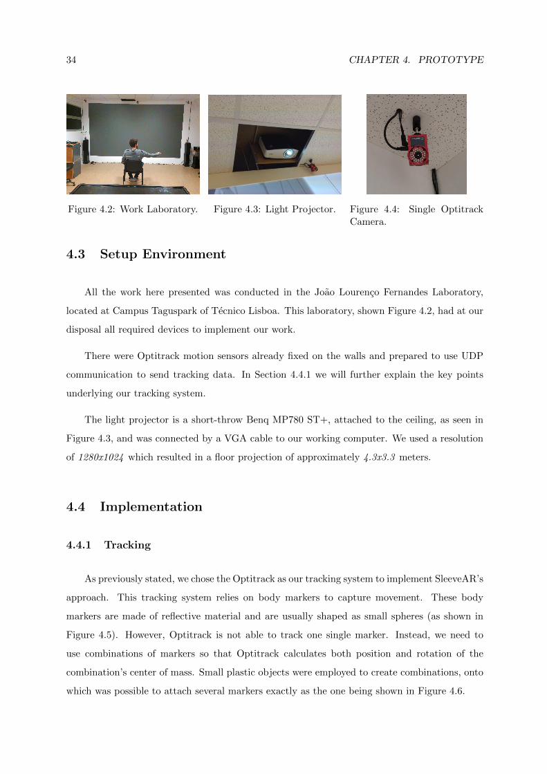
All the work here presented was conducted in the Joao Lourenco Fernandes Laboratory,
located at Campus Taguspark of Tecnico Lisboa. This laboratory, shown Figure 4.2, had at our
disposal all required devices to implement our work.
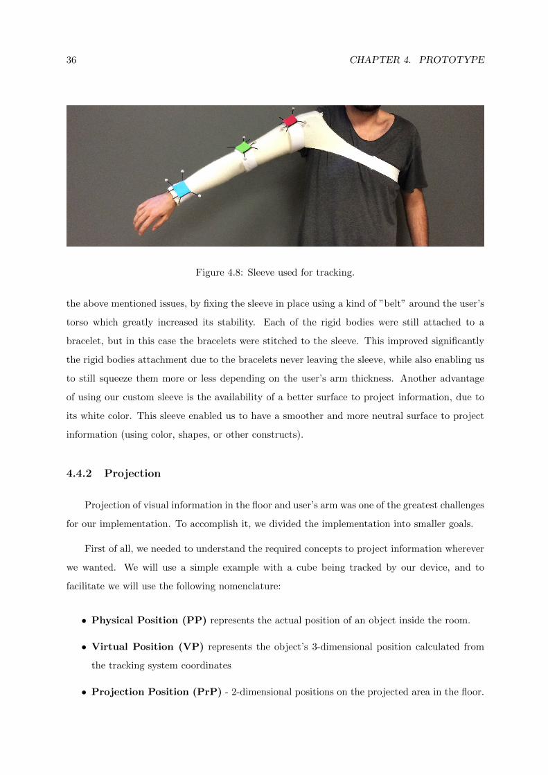
There were Optitrack motion sensors already fixed on the walls and prepared to use UDP
communication to send tracking data. In Section 4.4.1 we will further explain the key points
underlying our tracking system.
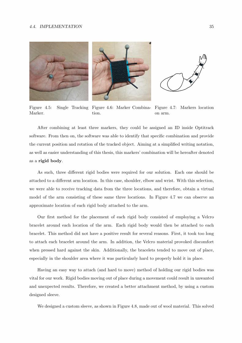
The light projector is a short-throw Benq MP780 ST+, attached to the ceiling, as seen in
Figure 4.3, and was connected by a VGA cable to our working computer. We used a resolution
of 1280x1024 which resulted in a floor projection of approximately 4.3x3.3 meters.
4.4 Implementation
4.4.1 Tracking
As previously stated, we chose the Optitrack as our tracking system to implement SleeveAR’s
approach. This tracking system relies on body markers to capture movement. These body
markers are made of reflective material and are usually shaped as small spheres (as shown in
Figure 4.5). However, Optitrack is not able to track one single marker. Instead, we need to
use combinations of markers so that Optitrack calculates both position and rotation of the
combination’s center of mass. Small plastic objects were employed to create combinations, onto
which was possible to attach several markers exactly as the one being shown in Figure 4.6.
4.4. IMPLEMENTATION 35
Figure 4.5: Single TrackingMarker.
Figure 4.6: Marker Combina-tion.
Figure 4.7: Markers locationon arm.
After combining at least three markers, they could be assigned an ID inside Optitrack
software. From then on, the software was able to identify that specific combination and provide
the current position and rotation of the tracked object. Aiming at a simplified writing notation,
as well as easier understanding of this thesis, this markers’ combination will be hereafter denoted
as a rigid body.
As such, three different rigid bodies were required for our solution. Each one should be
attached to a different arm location. In this case, shoulder, elbow and wrist. With this selection,
we were able to receive tracking data from the three locations, and therefore, obtain a virtual
model of the arm consisting of these same three locations. In Figure 4.7 we can observe an
approximate location of each rigid body attached to the arm.
Our first method for the placement of each rigid body consisted of employing a Velcro
bracelet around each location of the arm. Each rigid body would then be attached to each
bracelet. This method did not have a positive result for several reasons. First, it took too long
to attach each bracelet around the arm. In addition, the Velcro material provoked discomfort
when pressed hard against the skin. Additionally, the bracelets tended to move out of place,
especially in the shoulder area where it was particularly hard to properly hold it in place.
Having an easy way to attach (and hard to move) method of holding our rigid bodies was
vital for our work. Rigid bodies moving out of place during a movement could result in unwanted
and unexpected results. Therefore, we created a better attachment method, by using a custom
designed sleeve.
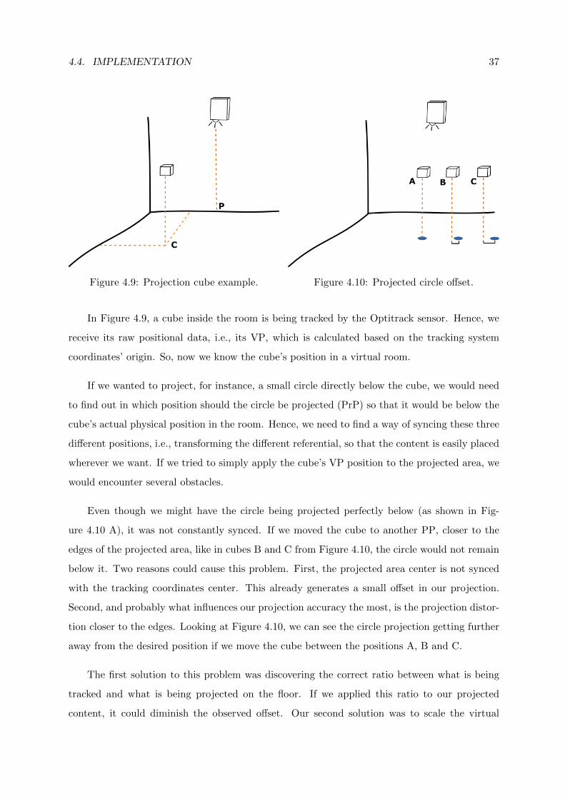
We designed a custom sleeve, as shown in Figure 4.8, made out of wool material. This solved
36 CHAPTER 4. PROTOTYPE
Figure 4.8: Sleeve used for tracking.
the above mentioned issues, by fixing the sleeve in place using a kind of ”belt” around the user’s
torso which greatly increased its stability. Each of the rigid bodies were still attached to a
bracelet, but in this case the bracelets were stitched to the sleeve. This improved significantly
the rigid bodies attachment due to the bracelets never leaving the sleeve, while also enabling us
to still squeeze them more or less depending on the user’s arm thickness. Another advantage
of using our custom sleeve is the availability of a better surface to project information, due to
its white color. This sleeve enabled us to have a smoother and more neutral surface to project
information (using color, shapes, or other constructs).
4.4.2 Projection
Projection of visual information in the floor and user’s arm was one of the greatest challenges
for our implementation. To accomplish it, we divided the implementation into smaller goals.
First of all, we needed to understand the required concepts to project information wherever
we wanted. We will use a simple example with a cube being tracked by our device, and to
facilitate we will use the following nomenclature:
• Physical Position (PP) represents the actual position of an object inside the room.
• Virtual Position (VP) represents the object’s 3-dimensional position calculated from
the tracking system coordinates
• Projection Position (PrP) - 2-dimensional positions on the projected area in the floor.
4.4. IMPLEMENTATION 37
Figure 4.9: Projection cube example. Figure 4.10: Projected circle offset.
In Figure 4.9, a cube inside the room is being tracked by the Optitrack sensor. Hence, we
receive its raw positional data, i.e., its VP, which is calculated based on the tracking system
coordinates’ origin. So, now we know the cube’s position in a virtual room.
If we wanted to project, for instance, a small circle directly below the cube, we would need
to find out in which position should the circle be projected (PrP) so that it would be below the
cube’s actual physical position in the room. Hence, we need to find a way of syncing these three
different positions, i.e., transforming the different referential, so that the content is easily placed
wherever we want. If we tried to simply apply the cube’s VP position to the projected area, we
would encounter several obstacles.
Even though we might have the circle being projected perfectly below (as shown in Fig-
ure 4.10 A), it was not constantly synced. If we moved the cube to another PP, closer to the
edges of the projected area, like in cubes B and C from Figure 4.10, the circle would not remain
below it. Two reasons could cause this problem. First, the projected area center is not synced
with the tracking coordinates center. This already generates a small offset in our projection.
Second, and probably what influences our projection accuracy the most, is the projection distor-
tion closer to the edges. Looking at Figure 4.10, we can see the circle projection getting further
away from the desired position if we move the cube between the positions A, B and C.
The first solution to this problem was discovering the correct ratio between what is being
tracked and what is being projected on the floor. If we applied this ratio to our projected
content, it could diminish the observed offset. Our second solution was to scale the virtual
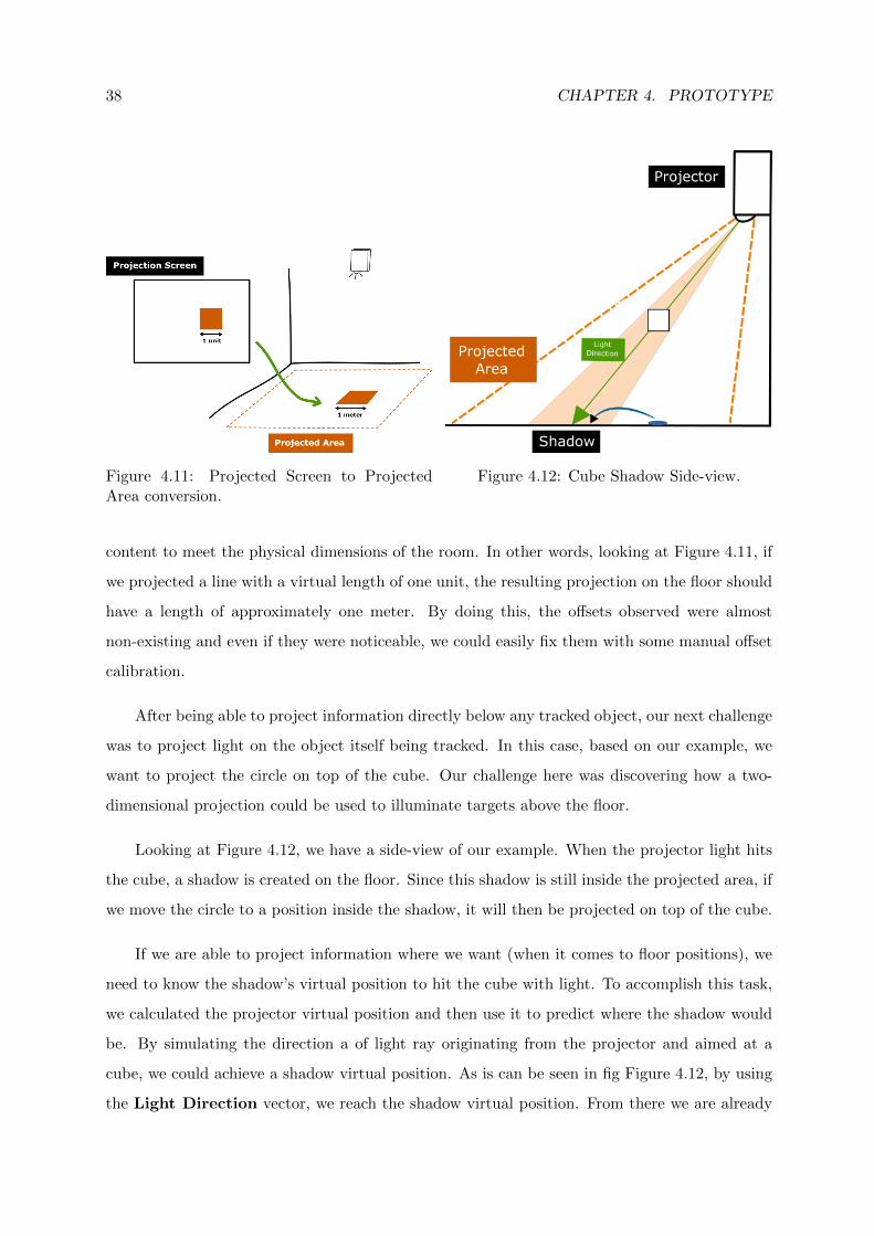
38 CHAPTER 4. PROTOTYPE
Figure 4.11: Projected Screen to ProjectedArea conversion.
Figure 4.12: Cube Shadow Side-view.
content to meet the physical dimensions of the room. In other words, looking at Figure 4.11, if
we projected a line with a virtual length of one unit, the resulting projection on the floor should
have a length of approximately one meter. By doing this, the offsets observed were almost
non-existing and even if they were noticeable, we could easily fix them with some manual offset
calibration.
After being able to project information directly below any tracked object, our next challenge
was to project light on the object itself being tracked. In this case, based on our example, we
want to project the circle on top of the cube. Our challenge here was discovering how a two-
dimensional projection could be used to illuminate targets above the floor.
Looking at Figure 4.12, we have a side-view of our example. When the projector light hits
the cube, a shadow is created on the floor. Since this shadow is still inside the projected area, if
we move the circle to a position inside the shadow, it will then be projected on top of the cube.
If we are able to project information where we want (when it comes to floor positions), we
need to know the shadow’s virtual position to hit the cube with light. To accomplish this task,
we calculated the projector virtual position and then use it to predict where the shadow would
be. By simulating the direction a of light ray originating from the projector and aimed at a
cube, we could achieve a shadow virtual position. As is can be seen in fig Figure 4.12, by using
the Light Direction vector, we reach the shadow virtual position. From there we are already
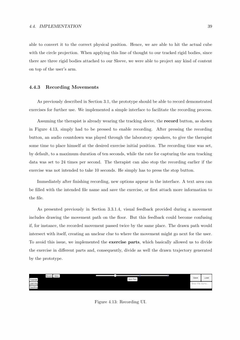
4.4. IMPLEMENTATION 39
able to convert it to the correct physical position. Hence, we are able to hit the actual cube
with the circle projection. When applying this line of thought to our tracked rigid bodies, since
there are three rigid bodies attached to our Sleeve, we were able to project any kind of content
on top of the user’s arm.
4.4.3 Recording Movements
As previously described in Section 3.1, the prototype should be able to record demonstrated
exercises for further use. We implemented a simple interface to facilitate the recording process.
Assuming the therapist is already wearing the tracking sleeve, the record button, as shown
in Figure 4.13, simply had to be pressed to enable recording. After pressing the recording
button, an audio countdown was played through the laboratory speakers, to give the therapist
some time to place himself at the desired exercise initial position. The recording time was set,
by default, to a maximum duration of ten seconds, while the rate for capturing the arm tracking
data was set to 24 times per second. The therapist can also stop the recording earlier if the
exercise was not intended to take 10 seconds. He simply has to press the stop button.
Immediately after finishing recording, new options appear in the interface. A text area can
be filled with the intended file name and save the exercise, or first attach more information to
the file.
As presented previously in Section 3.3.1.4, visual feedback provided during a movement
includes drawing the movement path on the floor. But this feedback could become confusing
if, for instance, the recorded movement passed twice by the same place. The drawn path would
intersect with itself, creating an unclear clue to where the movement might go next for the user.
To avoid this issue, we implemented the exercise parts, which basically allowed us to divide
the exercise in different parts and, consequently, divide as well the drawn trajectory generated
by the prototype.
Figure 4.13: Recording UI.
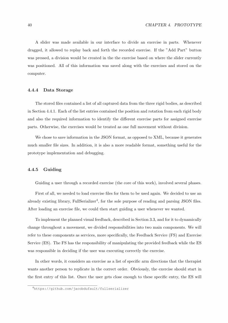
40 CHAPTER 4. PROTOTYPE
A slider was made available in our interface to divide an exercise in parts. Whenever
dragged, it allowed to replay back and forth the recorded exercise. If the ”Add Part” button
was pressed, a division would be created in the the exercise based on where the slider currently
was positioned. All of this information was saved along with the exercises and stored on the
computer.
4.4.4 Data Storage
The stored files contained a list of all captured data from the three rigid bodies, as described
in Section 4.4.1. Each of the list entries contained the position and rotation from each rigid body
and also the required information to identify the different exercise parts for assigned exercise
parts. Otherwise, the exercises would be treated as one full movement without division.
We chose to save information in the JSON format, as opposed to XML, because it generates
much smaller file sizes. In addition, it is also a more readable format, something useful for the
prototype implementation and debugging.
4.4.5 Guiding
Guiding a user through a recorded exercise (the core of this work), involved several phases.
First of all, we needed to load exercise files for them to be used again. We decided to use an
already existing library, FullSerializer4, for the sole purpose of reading and parsing JSON files.
After loading an exercise file, we could then start guiding a user whenever we wanted.
To implement the planned visual feedback, described in Section 3.3, and for it to dynamically
change throughout a movement, we divided responsibilities into two main components. We will
refer to these components as services, more specifically, the Feedback Service (FS) and Exercise
Service (ES). The FS has the responsibility of manipulating the provided feedback while the ES
was responsible in deciding if the user was executing correctly the exercise.
In other words, it considers an exercise as a list of specific arm directions that the therapist
wants another person to replicate in the correct order. Obviously, the exercise should start in
the first entry of this list. Once the user gets close enough to these specific entry, the ES will
4https://github.com/jacobdufault/fullserializer
4.4. IMPLEMENTATION 41
then advance to the next entry. This will keep happening until we reach the end of the list and
the exercise is over.
With this process in mind, every time ES is focused on a specific entry, the information
inside it will generate the so called visual feedback desired state. Therefore, grabbing the
concept of current and desired state from Section 3.3, two things will happen. First, FS will
update the current state based on real-time tracking from our current user. Second, the desired
state will be updated accordingly to the current entry ES is focusing on.
Even though we were tracking rigid bodies positions, we could not blindly compare between
the original and attempted positions. As explained in Section 2.3.1, the person which recorded
an exercise could have, for instance, a different arm length. Hence, even though we were storing
rigid bodies positions, we generated normalized vectors to represent the arm direction. Upper
arm direction was a normalized vector pointing from shoulder to elbow position, while the
forearm direction was a vector from elbow to wrist. By comparing the directions for both arm
regions, we eliminate the physical differences between different user’s arm.
4.4.6 Performance Review
Every time an exercise was finished, our prototype should present the user with a review
of his attempt. As described in our approach, the review should contain trajectory comparison
between the original exercise and user’s attempt. As for the score, we implemented a simple
formula to return a value from 0 to 100.
The score starts with 100 points. Considering the original exercise as a list of arm positions,
the user needs to advance through each position to finish the exercise, as explained previously.
Every time the patient gets too far away from the desired position, we start removing points
from his score. In other words, the more wrong movements are made, the lower the score will
be, eventually reaching 0. This scoring method is a proof of concept to help us develop and
evaluate our approach. It is accurate enough to give the user a general motivational awareness
of current progress. Despite that, this approach proved to be sufficient to spawn the desire to
improve their score, hence improve their overall performance. A picture of our performance
review implementation can be seen in Figure 3.1 D).

42 CHAPTER 4. PROTOTYPE
4.5 Summary
In this chapter we introduced the SleeveAR prototype and described its implementation.
Firstly, the architecture was presented, followed by the already existing devices that were used in
our implementation. Secondly,we described the obstacles found and techniques used regarding
the actual implementation of our prototype. In the following chapter, we describe the tasks and
methodologies performed to evaluate our prototype and present our statistical analysis of the
overall results.
5EvaluationSummary
To evaluate SleeveAR, we intended to observe how well a subject recreates simple arm
movements just by following the feedback at his disposal. Since tests involve executing simple
arm movements, five different exercises were created for this evaluation. These exercises were
simultaneously recorded both by video and by the SleeveAR’s recording features. This way, we
guarantee the same movement is being stored in video and in our system.
This chapter presents a detailed description of the experimental tests. It addresses the
experimental methodology employed for testing our prototype with test subjects, the category
of performed tests, the measurement metrics, and the characteristics of the collected sensor
information. It also presents the experimental results and their critical analysis. All the results
will be discussed in order to achieve a better understanding about our prototype functionality
and performance. Finally, the chapter reports some of the most important critics elaborated by
a professional physical therapist after using our system.
5.1 Methodology
This section describes the experimental methodologies for testing our prototype. Each
participant followed this methodology in a similar way.
# Stage Time
1 Introduction 2 minutes
2 SleeveAR 15 minutes
3 Video 10 minutes
4 Questionnaire 3 minutes
Table 5.1: SleeveAR evaluation stages
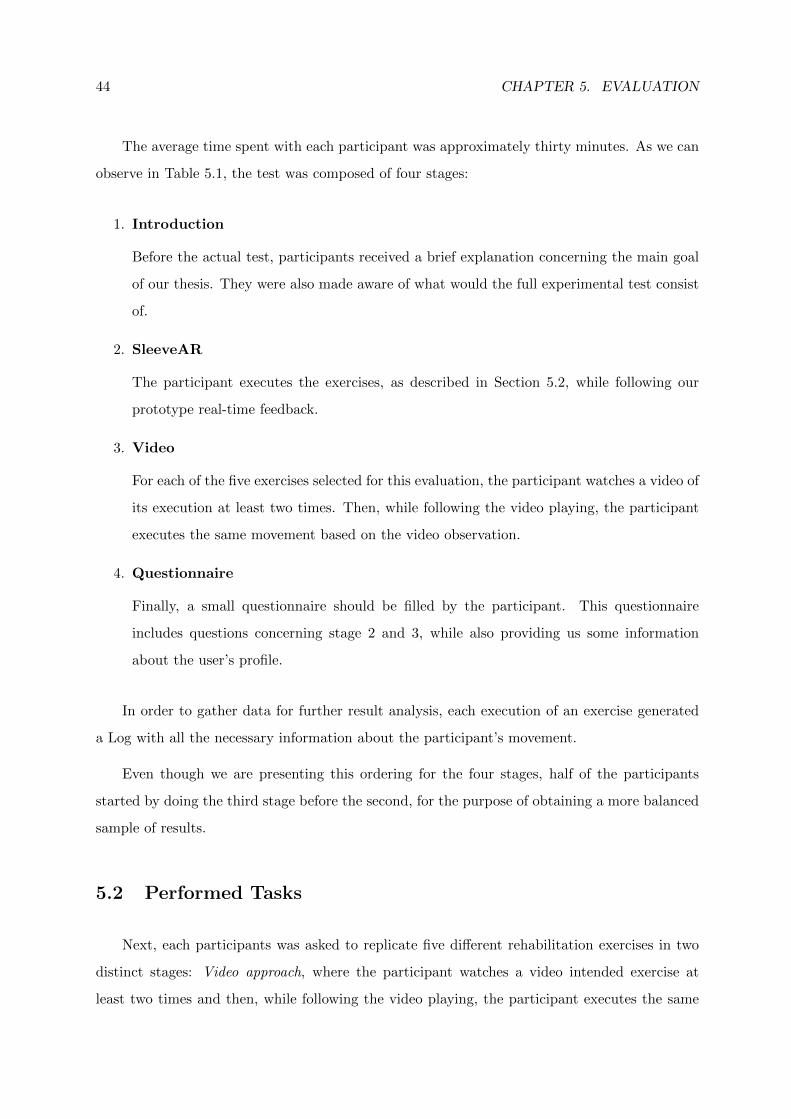
44 CHAPTER 5. EVALUATION
The average time spent with each participant was approximately thirty minutes. As we can
observe in Table 5.1, the test was composed of four stages:
1. Introduction
Before the actual test, participants received a brief explanation concerning the main goal
of our thesis. They were also made aware of what would the full experimental test consist
of.
2. SleeveAR
The participant executes the exercises, as described in Section 5.2, while following our
prototype real-time feedback.
3. Video
For each of the five exercises selected for this evaluation, the participant watches a video of
its execution at least two times. Then, while following the video playing, the participant
executes the same movement based on the video observation.
4. Questionnaire
Finally, a small questionnaire should be filled by the participant. This questionnaire
includes questions concerning stage 2 and 3, while also providing us some information
about the user’s profile.
In order to gather data for further result analysis, each execution of an exercise generated
a Log with all the necessary information about the participant’s movement.
Even though we are presenting this ordering for the four stages, half of the participants
started by doing the third stage before the second, for the purpose of obtaining a more balanced
sample of results.
5.2 Performed Tasks
Next, each participants was asked to replicate five different rehabilitation exercises in two
distinct stages: Video approach, where the participant watches a video intended exercise at
least two times and then, while following the video playing, the participant executes the same
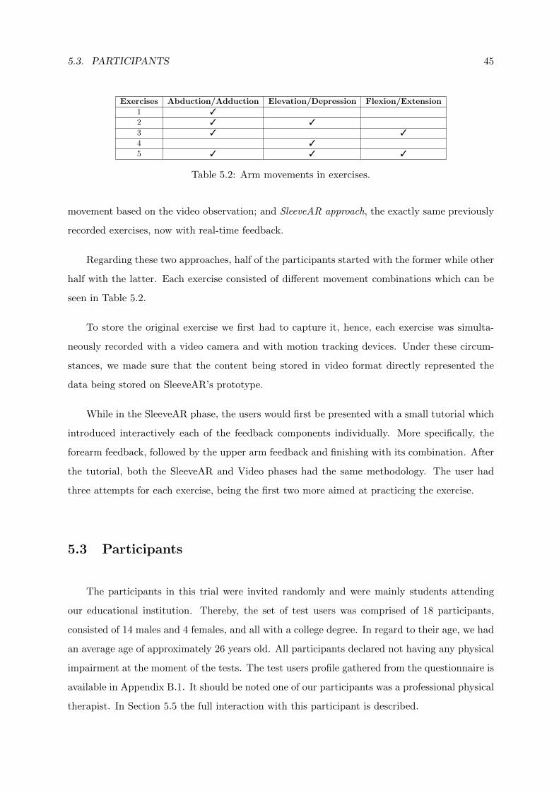
5.3. PARTICIPANTS 45
Exercises Abduction/Adduction Elevation/Depression Flexion/Extension
1 3
2 3 3
3 3 3
4 3
5 3 3 3
Table 5.2: Arm movements in exercises.
movement based on the video observation; and SleeveAR approach, the exactly same previously
recorded exercises, now with real-time feedback.
Regarding these two approaches, half of the participants started with the former while other
half with the latter. Each exercise consisted of different movement combinations which can be
seen in Table 5.2.
To store the original exercise we first had to capture it, hence, each exercise was simulta-
neously recorded with a video camera and with motion tracking devices. Under these circum-
stances, we made sure that the content being stored in video format directly represented the
data being stored on SleeveAR’s prototype.
While in the SleeveAR phase, the users would first be presented with a small tutorial which
introduced interactively each of the feedback components individually. More specifically, the
forearm feedback, followed by the upper arm feedback and finishing with its combination. After
the tutorial, both the SleeveAR and Video phases had the same methodology. The user had
three attempts for each exercise, being the first two more aimed at practicing the exercise.
5.3 Participants
The participants in this trial were invited randomly and were mainly students attending
our educational institution. Thereby, the set of test users was comprised of 18 participants,
consisted of 14 males and 4 females, and all with a college degree. In regard to their age, we had
an average age of approximately 26 years old. All participants declared not having any physical
impairment at the moment of the tests. The test users profile gathered from the questionnaire is
available in Appendix B.1. It should be noted one of our participants was a professional physical
therapist. In Section 5.5 the full interaction with this participant is described.
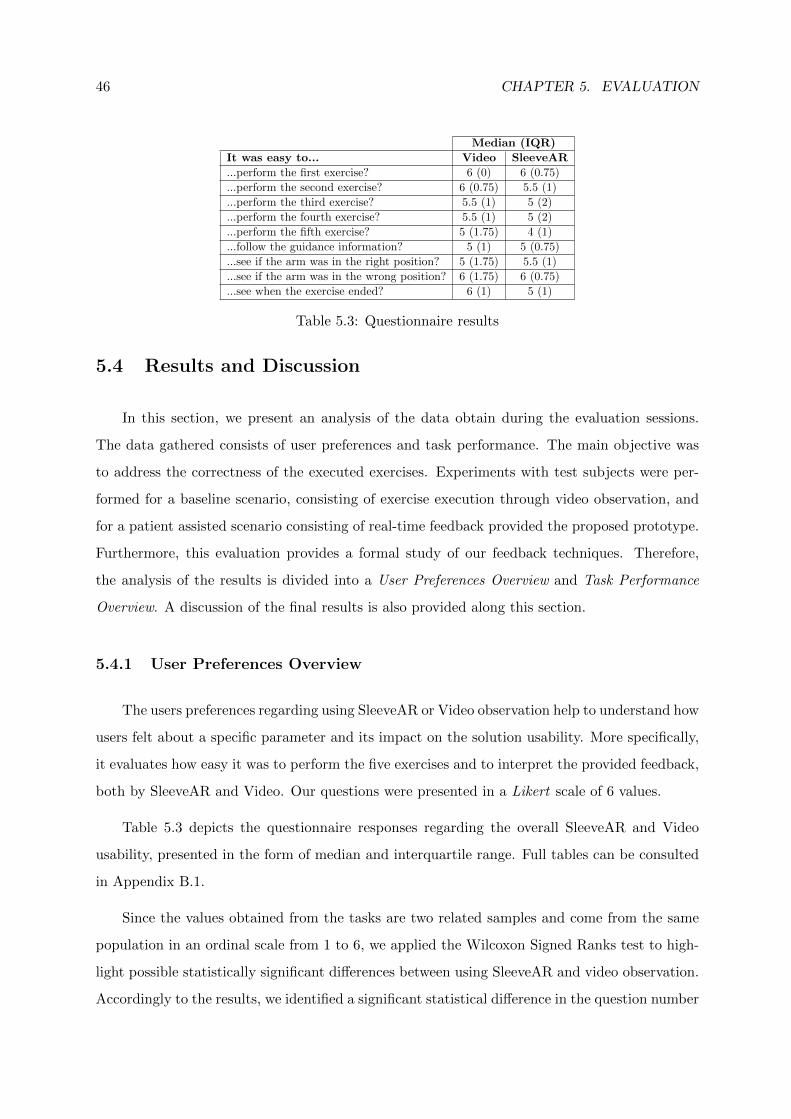
46 CHAPTER 5. EVALUATION
Median (IQR)
It was easy to... Video SleeveAR
...perform the first exercise? 6 (0) 6 (0.75)
...perform the second exercise? 6 (0.75) 5.5 (1)
...perform the third exercise? 5.5 (1) 5 (2)
...perform the fourth exercise? 5.5 (1) 5 (2)
...perform the fifth exercise? 5 (1.75) 4 (1)
...follow the guidance information? 5 (1) 5 (0.75)
...see if the arm was in the right position? 5 (1.75) 5.5 (1)
...see if the arm was in the wrong position? 6 (1.75) 6 (0.75)
...see when the exercise ended? 6 (1) 5 (1)
Table 5.3: Questionnaire results
5.4 Results and Discussion
In this section, we present an analysis of the data obtain during the evaluation sessions.
The data gathered consists of user preferences and task performance. The main objective was
to address the correctness of the executed exercises. Experiments with test subjects were per-
formed for a baseline scenario, consisting of exercise execution through video observation, and
for a patient assisted scenario consisting of real-time feedback provided the proposed prototype.
Furthermore, this evaluation provides a formal study of our feedback techniques. Therefore,
the analysis of the results is divided into a User Preferences Overview and Task Performance
Overview. A discussion of the final results is also provided along this section.
5.4.1 User Preferences Overview
The users preferences regarding using SleeveAR or Video observation help to understand how
users felt about a specific parameter and its impact on the solution usability. More specifically,
it evaluates how easy it was to perform the five exercises and to interpret the provided feedback,
both by SleeveAR and Video. Our questions were presented in a Likert scale of 6 values.
Table 5.3 depicts the questionnaire responses regarding the overall SleeveAR and Video
usability, presented in the form of median and interquartile range. Full tables can be consulted
in Appendix B.1.
Since the values obtained from the tasks are two related samples and come from the same
population in an ordinal scale from 1 to 6, we applied the Wilcoxon Signed Ranks test to high-
light possible statistically significant differences between using SleeveAR and video observation.
Accordingly to the results, we identified a significant statistical difference in the question number
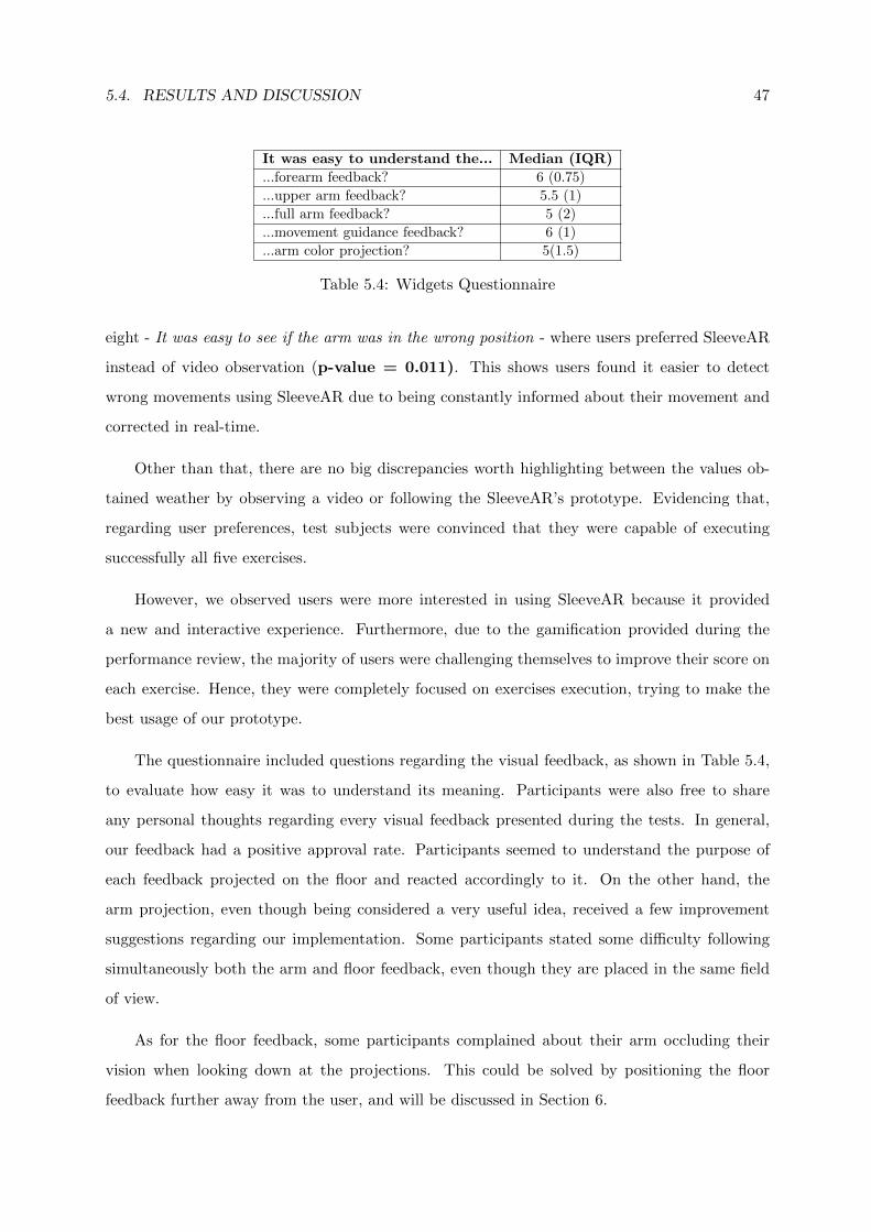
5.4. RESULTS AND DISCUSSION 47
It was easy to understand the... Median (IQR)
...forearm feedback? 6 (0.75)
...upper arm feedback? 5.5 (1)
...full arm feedback? 5 (2)
...movement guidance feedback? 6 (1)
...arm color projection? 5(1.5)
Table 5.4: Widgets Questionnaire
eight - It was easy to see if the arm was in the wrong position - where users preferred SleeveAR
instead of video observation (p-value = 0.011). This shows users found it easier to detect
wrong movements using SleeveAR due to being constantly informed about their movement and
corrected in real-time.
Other than that, there are no big discrepancies worth highlighting between the values ob-
tained weather by observing a video or following the SleeveAR’s prototype. Evidencing that,
regarding user preferences, test subjects were convinced that they were capable of executing
successfully all five exercises.
However, we observed users were more interested in using SleeveAR because it provided
a new and interactive experience. Furthermore, due to the gamification provided during the
performance review, the majority of users were challenging themselves to improve their score on
each exercise. Hence, they were completely focused on exercises execution, trying to make the
best usage of our prototype.
The questionnaire included questions regarding the visual feedback, as shown in Table 5.4,
to evaluate how easy it was to understand its meaning. Participants were also free to share
any personal thoughts regarding every visual feedback presented during the tests. In general,
our feedback had a positive approval rate. Participants seemed to understand the purpose of
each feedback projected on the floor and reacted accordingly to it. On the other hand, the
arm projection, even though being considered a very useful idea, received a few improvement
suggestions regarding our implementation. Some participants stated some difficulty following
simultaneously both the arm and floor feedback, even though they are placed in the same field
of view.
As for the floor feedback, some participants complained about their arm occluding their
vision when looking down at the projections. This could be solved by positioning the floor
feedback further away from the user, and will be discussed in Section 6.
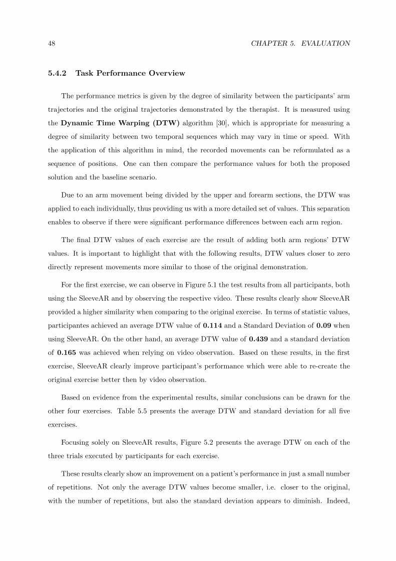
48 CHAPTER 5. EVALUATION
5.4.2 Task Performance Overview
The performance metrics is given by the degree of similarity between the participants’ arm
trajectories and the original trajectories demonstrated by the therapist. It is measured using
the Dynamic Time Warping (DTW) algorithm [30], which is appropriate for measuring a
degree of similarity between two temporal sequences which may vary in time or speed. With
the application of this algorithm in mind, the recorded movements can be reformulated as a
sequence of positions. One can then compare the performance values for both the proposed
solution and the baseline scenario.
Due to an arm movement being divided by the upper and forearm sections, the DTW was
applied to each individually, thus providing us with a more detailed set of values. This separation
enables to observe if there were significant performance differences between each arm region.
The final DTW values of each exercise are the result of adding both arm regions’ DTW
values. It is important to highlight that with the following results, DTW values closer to zero
directly represent movements more similar to those of the original demonstration.
For the first exercise, we can observe in Figure 5.1 the test results from all participants, both
using the SleeveAR and by observing the respective video. These results clearly show SleeveAR
provided a higher similarity when comparing to the original exercise. In terms of statistic values,
participantes achieved an average DTW value of 0.114 and a Standard Deviation of 0.09 when
using SleeveAR. On the other hand, an average DTW value of 0.439 and a standard deviation
of 0.165 was achieved when relying on video observation. Based on these results, in the first
exercise, SleeveAR clearly improve participant’s performance which were able to re-create the
original exercise better then by video observation.
Based on evidence from the experimental results, similar conclusions can be drawn for the
other four exercises. Table 5.5 presents the average DTW and standard deviation for all five
exercises.
Focusing solely on SleeveAR results, Figure 5.2 presents the average DTW on each of the
three trials executed by participants for each exercise.
These results clearly show an improvement on a patient’s performance in just a small number
of repetitions. Not only the average DTW values become smaller, i.e. closer to the original,
with the number of repetitions, but also the standard deviation appears to diminish. Indeed,
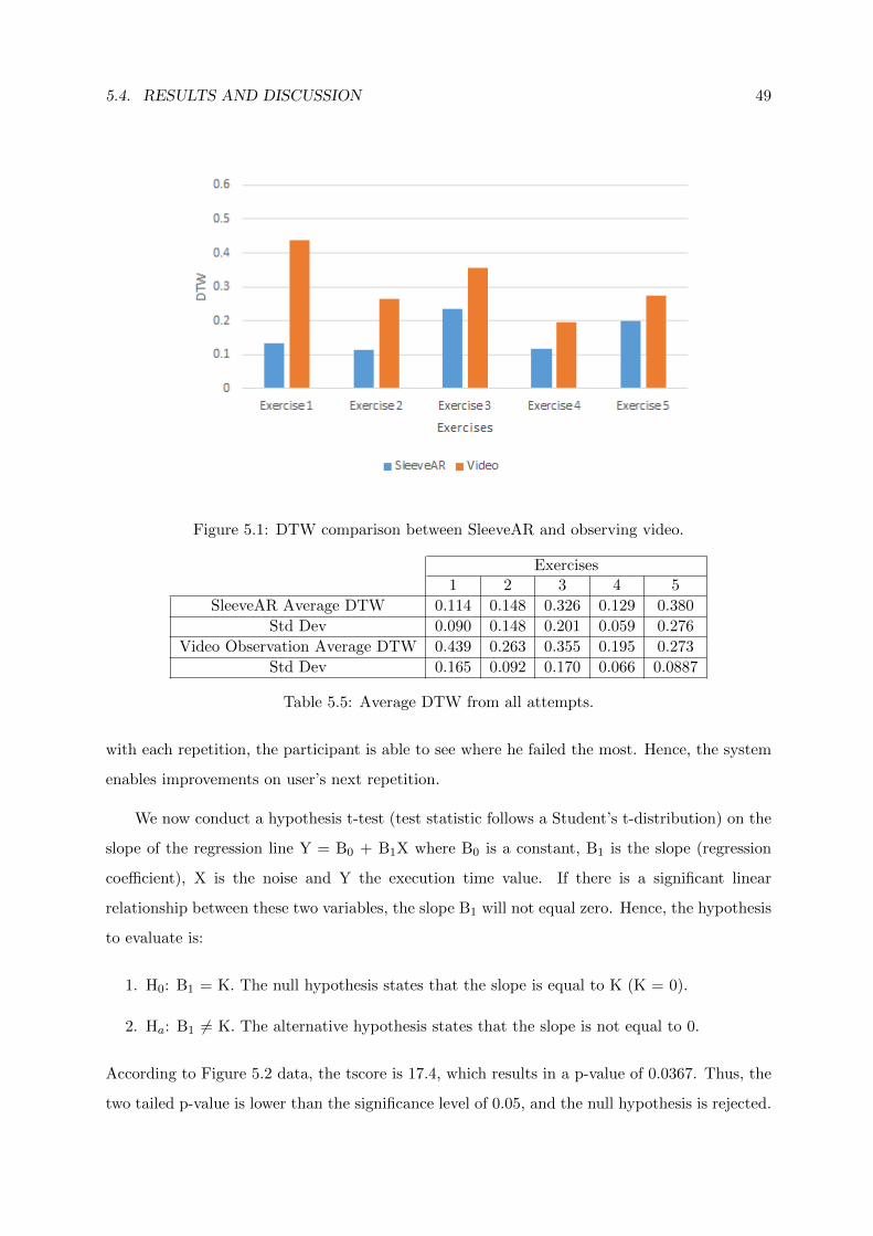
5.4. RESULTS AND DISCUSSION 49
Figure 5.1: DTW comparison between SleeveAR and observing video.
Exercises1 2 3 4 5
SleeveAR Average DTW 0.114 0.148 0.326 0.129 0.380
Std Dev 0.090 0.148 0.201 0.059 0.276
Video Observation Average DTW 0.439 0.263 0.355 0.195 0.273
Std Dev 0.165 0.092 0.170 0.066 0.0887
Table 5.5: Average DTW from all attempts.
with each repetition, the participant is able to see where he failed the most. Hence, the system
enables improvements on user’s next repetition.
We now conduct a hypothesis t-test (test statistic follows a Student’s t-distribution) on the
slope of the regression line Y = B0 + B1X where B0 is a constant, B1 is the slope (regression
coefficient), X is the noise and Y the execution time value. If there is a significant linear
relationship between these two variables, the slope B1 will not equal zero. Hence, the hypothesis
to evaluate is:
1. H0: B1 = K. The null hypothesis states that the slope is equal to K (K = 0).
2. Ha: B1 6= K. The alternative hypothesis states that the slope is not equal to 0.
According to Figure 5.2 data, the tscore is 17.4, which results in a p-value of 0.0367. Thus, the
two tailed p-value is lower than the significance level of 0.05, and the null hypothesis is rejected.
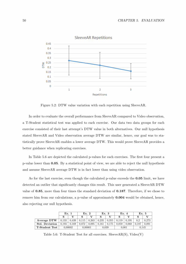
50 CHAPTER 5. EVALUATION
Figure 5.2: DTW value variation with each repetition using SleeveAR.
In order to evaluate the overall performance from SleeveAR compared to Video observation,
a T-Student statistical test was applied to each exercise. Our data two data groups for each
exercise consisted of their last attempt’s DTW value in both alternatives. Our null hypothesis
stated SleeveAR and Video observation average DTW are similar, hence, our goal was to sta-
tistically prove SleeveAR enables a lower average DTW. This would prove SleeveAR provides a
better guidance when replicating exercises.
In Table 5.6 are depicted the calculated p-values for each exercises. The first four present a
p-value lower than 0.05. By a statistical point of view, we are able to reject the null hypothesis
and assume SleeveAR average DTW is in fact lower than using video observation.
As for the last exercise, even though the calculated p-value exceeds the 0.05 limit, we have
detected an outlier that significantly changes this result. This user generated a SleeveAR DTW
value of 0.85, more than four times the standard deviation of 0.187. Therefore, if we chose to
remove him from our calculations, a p-value of approximately 0.004 would be obtained, hence,
also rejecting our null hypothesis.
Ex. 1 Ex. 2 Ex. 3 Ex. 4 Ex. 5S V S V S V S V S V
Average DTW 0,133 0,439 0,115 0,263 0,235 0,355 0,119 0,195 0,2 0,273
Std. Deviation 0,193 0,169 0,072 0,095 0,161 0,175 0,059 0,068 0,187 0,091
T-Student Test 0,00002 0,00001 0,039 0,001 0,145
Table 5.6: T-Student Test for all exercises. SleeveAR(S), Video(V)
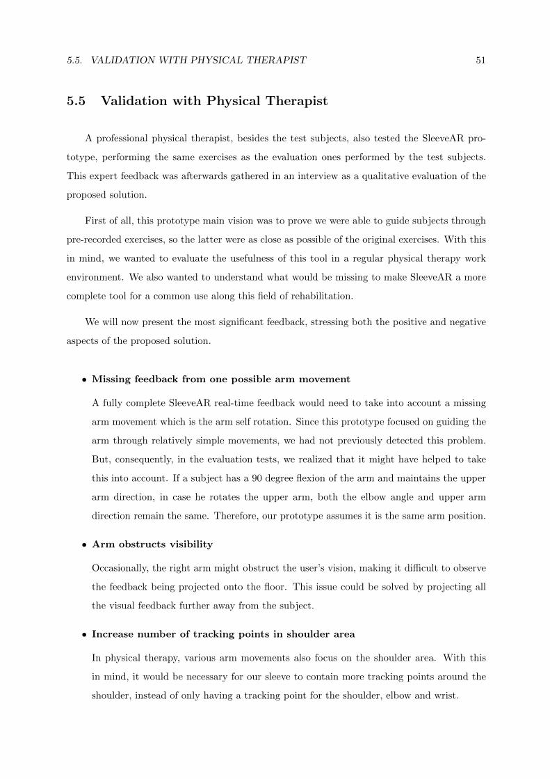
5.5. VALIDATION WITH PHYSICAL THERAPIST 51
5.5 Validation with Physical Therapist
A professional physical therapist, besides the test subjects, also tested the SleeveAR pro-
totype, performing the same exercises as the evaluation ones performed by the test subjects.
This expert feedback was afterwards gathered in an interview as a qualitative evaluation of the
proposed solution.
First of all, this prototype main vision was to prove we were able to guide subjects through
pre-recorded exercises, so the latter were as close as possible of the original exercises. With this
in mind, we wanted to evaluate the usefulness of this tool in a regular physical therapy work
environment. We also wanted to understand what would be missing to make SleeveAR a more
complete tool for a common use along this field of rehabilitation.
We will now present the most significant feedback, stressing both the positive and negative
aspects of the proposed solution.
• Missing feedback from one possible arm movement
A fully complete SleeveAR real-time feedback would need to take into account a missing
arm movement which is the arm self rotation. Since this prototype focused on guiding the
arm through relatively simple movements, we had not previously detected this problem.
But, consequently, in the evaluation tests, we realized that it might have helped to take
this into account. If a subject has a 90 degree flexion of the arm and maintains the upper
arm direction, in case he rotates the upper arm, both the elbow angle and upper arm
direction remain the same. Therefore, our prototype assumes it is the same arm position.
• Arm obstructs visibility
Occasionally, the right arm might obstruct the user’s vision, making it difficult to observe
the feedback being projected onto the floor. This issue could be solved by projecting all
the visual feedback further away from the subject.
• Increase number of tracking points in shoulder area
In physical therapy, various arm movements also focus on the shoulder area. With this
in mind, it would be necessary for our sleeve to contain more tracking points around the
shoulder, instead of only having a tracking point for the shoulder, elbow and wrist.
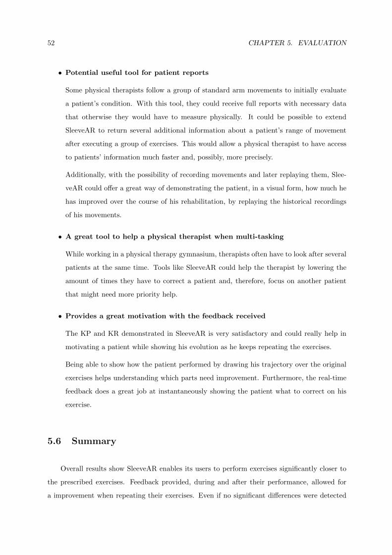
52 CHAPTER 5. EVALUATION
• Potential useful tool for patient reports
Some physical therapists follow a group of standard arm movements to initially evaluate
a patient’s condition. With this tool, they could receive full reports with necessary data
that otherwise they would have to measure physically. It could be possible to extend
SleeveAR to return several additional information about a patient’s range of movement
after executing a group of exercises. This would allow a physical therapist to have access
to patients’ information much faster and, possibly, more precisely.
Additionally, with the possibility of recording movements and later replaying them, Slee-
veAR could offer a great way of demonstrating the patient, in a visual form, how much he
has improved over the course of his rehabilitation, by replaying the historical recordings
of his movements.
• A great tool to help a physical therapist when multi-tasking
While working in a physical therapy gymnasium, therapists often have to look after several
patients at the same time. Tools like SleeveAR could help the therapist by lowering the
amount of times they have to correct a patient and, therefore, focus on another patient
that might need more priority help.
• Provides a great motivation with the feedback received
The KP and KR demonstrated in SleeveAR is very satisfactory and could really help in
motivating a patient while showing his evolution as he keeps repeating the exercises.
Being able to show how the patient performed by drawing his trajectory over the original
exercises helps understanding which parts need improvement. Furthermore, the real-time
feedback does a great job at instantaneously showing the patient what to correct on his
exercise.
5.6 Summary
Overall results show SleeveAR enables its users to perform exercises significantly closer to
the prescribed exercises. Feedback provided, during and after their performance, allowed for
a improvement when repeating their exercises. Even if no significant differences were detected

5.6. SUMMARY 53
on user preference between following SleeveAR or observing video instructions, the task per-
formance results clearly show SleeveAR would be a better alternative due to providing user
correction in situations they would have none. Our validation with a physical therapist was
vital to enumerate what could still be improved or added to our solution. It also confirmed
SleeveAR as a possible tool in the rehabilitation field which could facilitate a therapists work in
a more advanced phase.

54 CHAPTER 5. EVALUATION
6Conclusions and Future
Work
Augmented reality with visual feedback for rehabilitation is expected to provide a patient
with improved sources and correction when executing exercises outside of a clinic. This would
be preferred, as opposed to exercising with no feedback where there is no way of correcting
the execution. The state of the art presents several solutions to provide guidance during move-
ment’s execution. However, there is still room for improvement, and much research is needed to
determine the optimal combination of different feedback sources Projecting light on top of the
limbs to guide a subject through a movement had some promising results, still it is difficult for
patients to accurately replicate the rehabilitation exercise prescribed.
We have introduced SleeveAR, which brings augmented reality feedback and movement
guidance to therapeutic and rehabilitation exercises. Not only to precisely guide people in how
to perform, but also, to provide simple and clear awareness of the exactitude or the incorrectness
of the required actions, using visual and audio cues. With SleeveAR, patients are able to to
formally assess feedback combinations suitable for movement guidance while solving some of the
perception problems and also contribute with different feedback techniques in addition to the
ones observed in the state of the art. Furthermore, results from user tests suggests that people
can replicate previously pre-recorded movements by following our proposed feedback approaches.
As for future work, several aspects will be taken into account. We intend to maintain a
collaboration with physical therapists in order to pursue the development of a prototype that
could be used in the professional field. With the feedback received in our validation with a
therapist, we aim to solve the identified issues in order to improve our prototype. This includes
covering all possible arm movements and, if possible, extend SleeveAR to other body parts.
By maintaining a collaboration with field professionals, we also intend to gather more re-
quirements that could improve SleeveAR and actually test our prototype on a real therapeutic
environment with real patients. We also want to invest more time on implementing a more
complex audio feedback and introduce haptic feedback into our approach.

56 CHAPTER 6. CONCLUSIONS AND FUTURE WORK
References
[1] R. Sodhi, H. Benko, and A. Wilson, “LightGuide: projected visualizations for hand move-
ment guidance,” Proceedings of the SIGCHI Conference on Human Factors in Comput-
ing Systems, 2012.
[2] A. Singh, A. Klapper, and J. Jia, “Motivating people with chronic pain to do physical
activity: opportunities for technology design,” Proceedings of the SIGCHI Conference
on Human Factors in Computing Systems, pp. 2803–2812, 2014.
[3] A. D. Gama, T. Chaves, L. Figueiredo, and V. Teichrieb, “Guidance and Movement Cor-
rection Based on Therapeutics Movements for Motor Rehabilitation Support Systems,”
2012 14th Symposium on Virtual and Augmented Reality, pp. 191–200, May 2012.
[4] R. Sigrist, G. Rauter, R. Riener, and P. Wolf, “Augmented visual, auditory, haptic, and
multimodal feedback in motor learning: A review,” Psychonomic bulletin & review,
vol. 20, pp. 21–53, Feb. 2013.
[5] K. Lohse, N. Shirzad, and A. Verster, “Video Games and Rehabilitation: Using Design
Principles to Enhance Engagement in Physical Therapy,” Journal of Neurologic Physical
Therapy, vol. 37, pp. 166–75, Dec. 2013.
[6] N. A. Borghese, R. Mainetti, M. Pirovano, and P. L. Lanzi, “An intelligent game engine for
the at-home rehabilitation of stroke patients,” 2013 IEEE 2nd International Conference
on Serious Games and Applications for Health (SeGAH), pp. 1–8, May 2013.
[7] R. Tang, H. Alizadeh, A. Tang, S. Bateman, and J. Jorge, “Physio@ Home: design explo-
rations to support movement guidance,” CHI ’14 Extended Abstracts on Human Factors
in Computing Systems, 2014.
[8] C. Schonauer and T. Pintaric, “Full Body Interaction for Serious Games in Motor Rehabili-
tation,” Proceedings of the 2Nd Augmented Human International Conference, vol. ACM
Press, pp. 1–8, 2011.
[9] M. Balaam, S. Rennick Egglestone, G. Fitzpatrick, T. Rodden, A.-M. Hughes, A. Wilkinson,
57
58 CHAPTER 6. CONCLUSIONS AND FUTURE WORK
T. Nind, L. Axelrod, E. Harris, I. Ricketts, S. Mawson, and J. Burridge, “Motivating
mobility: designing for lived motivation in stroke rehabilitation,” Proceedings of the
SIGCHI Conference on Human Factors in Computing Systems, 2011.
[10] P. Rego, P. Moreira, and L. Reis, “Serious games for rehabilitation: A survey and a clas-
sification towards a taxonomy,” Information Systems and Technologies (CISTI), 2010
5th Iberian Conference on, 2010.
[11] N. Kitsunezaki, E. Adachi, T. Masuda, and J.-i. Mizusawa, “KINECT applications for the
physical rehabilitation,” 2013 IEEE International Symposium on Medical Measurements
and Applications (MeMeA), pp. 294–299, May 2013.
[12] H. Huang, T. Ingalls, L. Olson, K. Ganley, T. Rikakis, and J. He, “Interactive multimodal
biofeedback for task-oriented neural rehabilitation,” Engineering in Medicine and Bi-
ology Society, 2005. IEEE-EMBS 2005. 27th Annual International Conference of the,
pp. 2547–2550, 2005.
[13] D. Sadihov, B. Migge, and R. Gassert, “Prototype of a VR upper-limb rehabilitation system
enhanced with motion-based tactile feedback,” 2013 World Haptics Conference (WHC),
pp. 449–454, Apr. 2013.
[14] J. W. Burke, M. McNeill, D. Charles, P. Morrow, J. Crosbie, and S. McDonough, “Serious
Games for Upper Limb Rehabilitation Following Stroke,” 2009 Conference in Games
and Virtual Worlds for Serious Applications, pp. 103–110, Mar. 2009.
[15] A. Klein and G. A. D. Assis, “A Markeless Augmented Reality Tracking for Enhancing the
User Interaction during Virtual Rehabilitation,” 2013 XV Symposium on Virtual and
Augmented Reality, pp. 117–124, May 2013.
[16] G. Burdea, “Virtual Rehabilitation- Benefits and Challenges,” 2002.
[17] C. Schonauer and T. Pintaric, “Chronic pain rehabilitation with a serious game using
multimodal input,” Virtual Rehabilitation (ICVR), 2011 International Conference on,
2011.
[18] M. Ma and K. Bechkoum, “Serious games for movement therapy after stroke,” 2008 IEEE
International Conference on Systems, Man and Cybernetics, pp. 1872–1877, Oct. 2008.
[19] B. Lange, S. Koenig, E. McConnell, C.-Y. Chang, R. Juang, E. Suma, M. Bolas, and
A. Rizzo, “Interactive game-based rehabilitation using the Microsoft Kinect,” 2012
59
IEEE Virtual Reality (VR), pp. 171–172, Mar. 2012.
[20] M. D. P. Guimaraes, V. V. F. Martins, and M. Guimaraes, “A Checklist to Evaluate
Augmented Reality Applications,” Virtual and Augmented Reality (SVR), 2014 XVI
Symposium on, pp. 45–52, May 2014.
[21] F. Anderson, T. Grossman, J. Matejka, and G. Fitzmaurice, “YouMove: Enhancing Move-
ment Training with an Augmented Reality Mirror,” Proceedings of the 26th Annual
ACM Symposium on User Interface Software and Technology, pp. 311—-320, 2013.
[22] E. Velloso, A. Bulling, and H. Gellersen, “MotionMA: Motion modelling and analysis by
demonstration,” Proceedings of the SIGCHI Conference on Human Factors in Comput-
ing Systems, pp. 1309–1318, 2013.
[23] M. F. Alhamid, M. Eid, and A. E. Saddik, “A multi-modal intelligent system for biofeed-
back interactions,” 2012 IEEE International Symposium on Medical Measurements and
Applications Proceedings, pp. 1–5, May 2012.
[24] T. Blum and V. Kleeberger, “mirracle: An augmented reality magic mirror system
for anatomy education,” Computer Aided Medical Procedures & Augmented Reality,
pp. 115–116, 2012.
[25] J. Hattingh and A. Demafiles, “3D Projection Mapping promoting ”The Tourist” in Dallas
- https://www.youtube.com/watch?v=XSR0Xady02o.”
[26] N. Barbosa, “Emmy Curl - Come Closer - http://vimeo.com/113000956,” 2014.
[27] A. Scano, M. Caimmi, M. Malosio, and L. M. Tosatti, “Using Kinect for upper-limb func-
tional evaluation in home rehabilitation: A comparison with a 3D stereoscopic pas-
sive marker system,” 5th IEEE RAS/EMBS International Conference on Biomedical
Robotics and Biomechatronics, pp. 561–566, Aug. 2014.
[28] C. Chang, B. Lange, and M. Zhang, “Towards pervasive physical rehabilitation using Mi-
crosoft Kinect,” Pervasive Computing Technologies for Healthcare (PervasiveHealth),
2012 6th International Conference on, pp. 159–162, 2012.
[29] M. Wellner, A. Schaufelberger, and R. Riener, “A study on sound feedback in a virtual
environment for gait rehabilitation,” Virtual Rehabilitation, pp. 53–56, 2007.
[30] J. B. Kruskal and M. Liberman, “The symmetric time-warping problem: from continuous
to discrete,” Time Warps, String Edits and Macromolecules: The Theory and Practice

60 CHAPTER 6. CONCLUSIONS AND FUTURE WORK
of Sequence Comparison, pp. 125–161, 1983.

ATask Performance
A.1 T-Student Test Full Tables
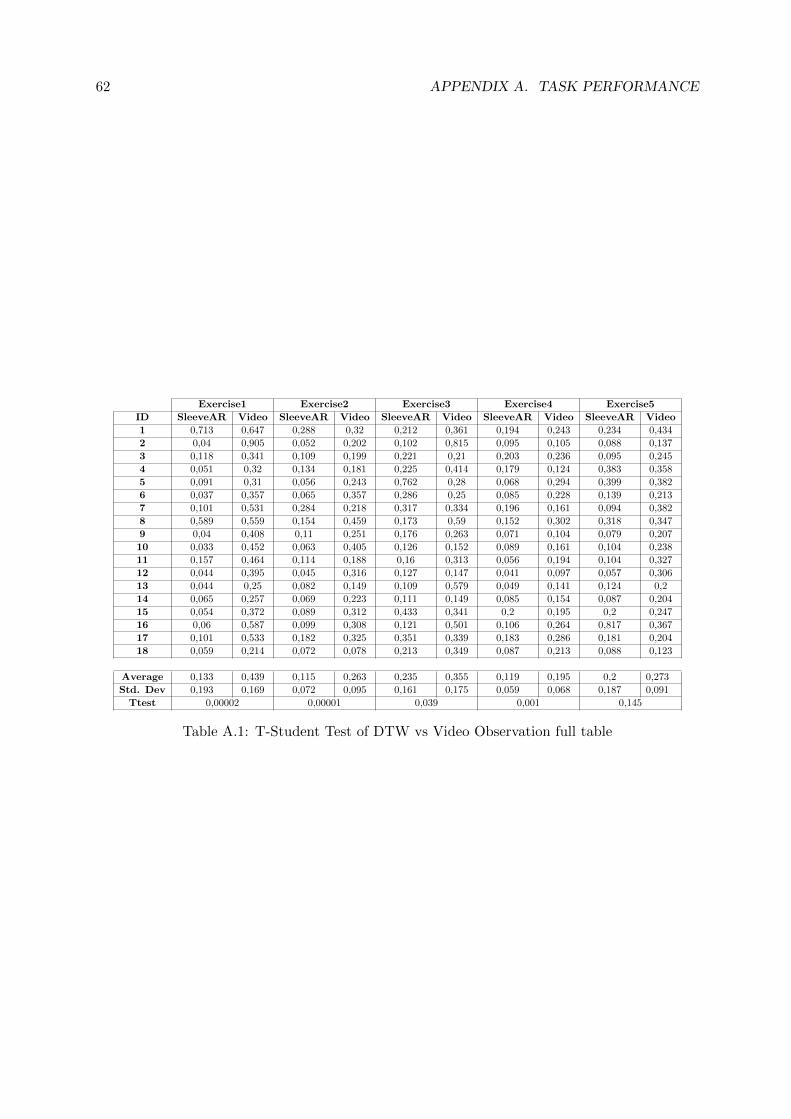
62 APPENDIX A. TASK PERFORMANCE
Exercise1 Exercise2 Exercise3 Exercise4 Exercise5
ID SleeveAR Video SleeveAR Video SleeveAR Video SleeveAR Video SleeveAR Video
1 0,713 0,647 0,288 0,32 0,212 0,361 0,194 0,243 0,234 0,434
2 0,04 0,905 0,052 0,202 0,102 0,815 0,095 0,105 0,088 0,137
3 0,118 0,341 0,109 0,199 0,221 0,21 0,203 0,236 0,095 0,245
4 0,051 0,32 0,134 0,181 0,225 0,414 0,179 0,124 0,383 0,358
5 0,091 0,31 0,056 0,243 0,762 0,28 0,068 0,294 0,399 0,382
6 0,037 0,357 0,065 0,357 0,286 0,25 0,085 0,228 0,139 0,213
7 0,101 0,531 0,284 0,218 0,317 0,334 0,196 0,161 0,094 0,382
8 0,589 0,559 0,154 0,459 0,173 0,59 0,152 0,302 0,318 0,347
9 0,04 0,408 0,11 0,251 0,176 0,263 0,071 0,104 0,079 0,207
10 0,033 0,452 0,063 0,405 0,126 0,152 0,089 0,161 0,104 0,238
11 0,157 0,464 0,114 0,188 0,16 0,313 0,056 0,194 0,104 0,327
12 0,044 0,395 0,045 0,316 0,127 0,147 0,041 0,097 0,057 0,306
13 0,044 0,25 0,082 0,149 0,109 0,579 0,049 0,141 0,124 0,2
14 0,065 0,257 0,069 0,223 0,111 0,149 0,085 0,154 0,087 0,204
15 0,054 0,372 0,089 0,312 0,433 0,341 0,2 0,195 0,2 0,247
16 0,06 0,587 0,099 0,308 0,121 0,501 0,106 0,264 0,817 0,367
17 0,101 0,533 0,182 0,325 0,351 0,339 0,183 0,286 0,181 0,204
18 0,059 0,214 0,072 0,078 0,213 0,349 0,087 0,213 0,088 0,123
Average 0,133 0,439 0,115 0,263 0,235 0,355 0,119 0,195 0,2 0,273
Std. Dev 0,193 0,169 0,072 0,095 0,161 0,175 0,059 0,068 0,187 0,091
Ttest 0,00002 0,00001 0,039 0,001 0,145
Table A.1: T-Student Test of DTW vs Video Observation full table

BUser Preferences
B.1 Questionnaire
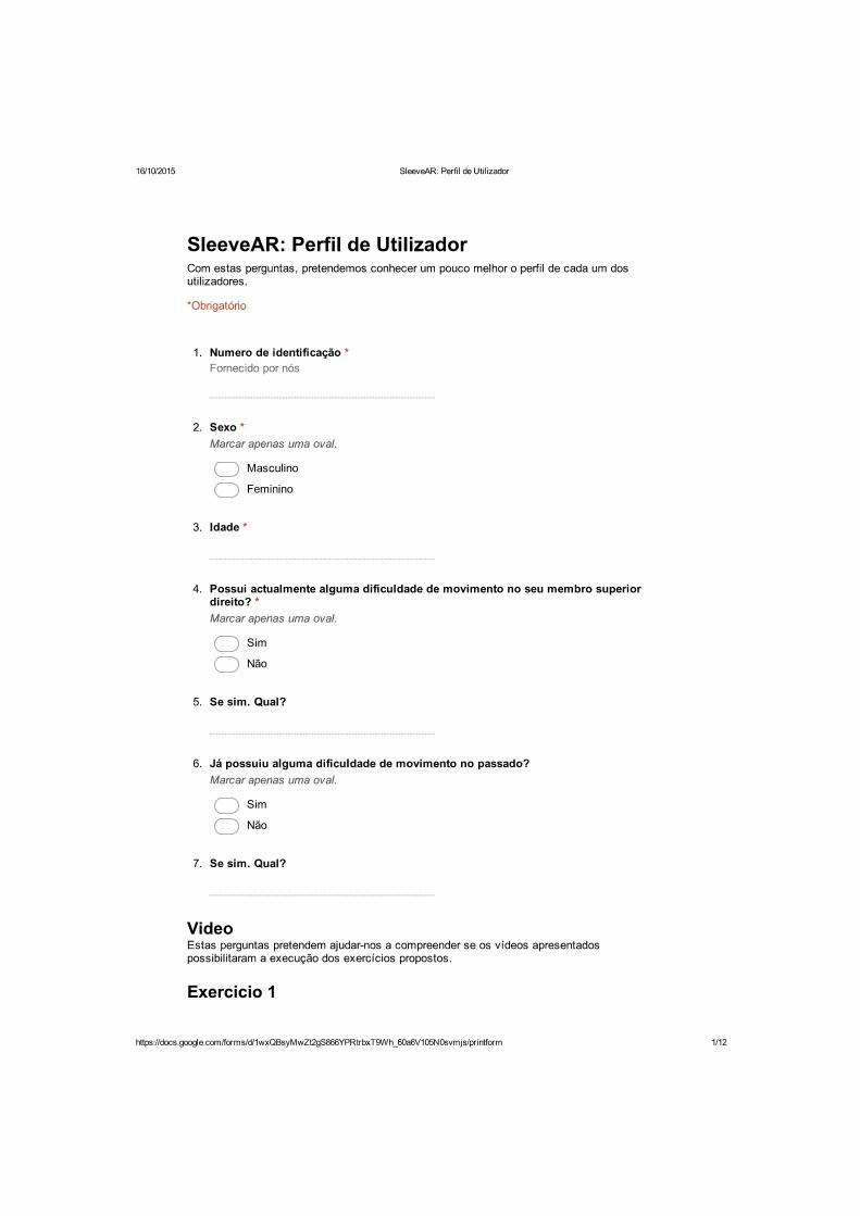


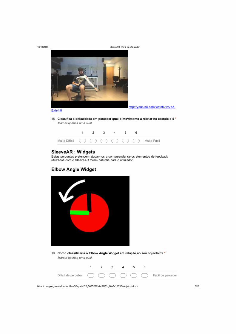
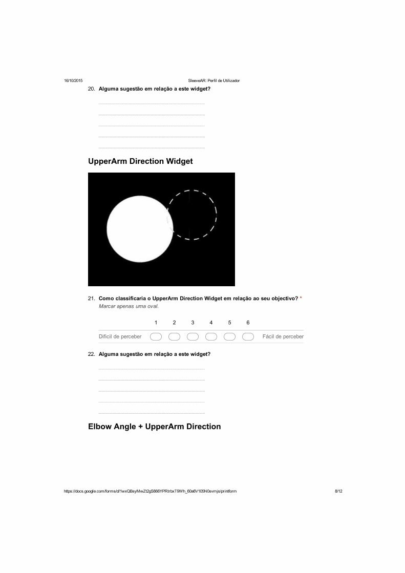
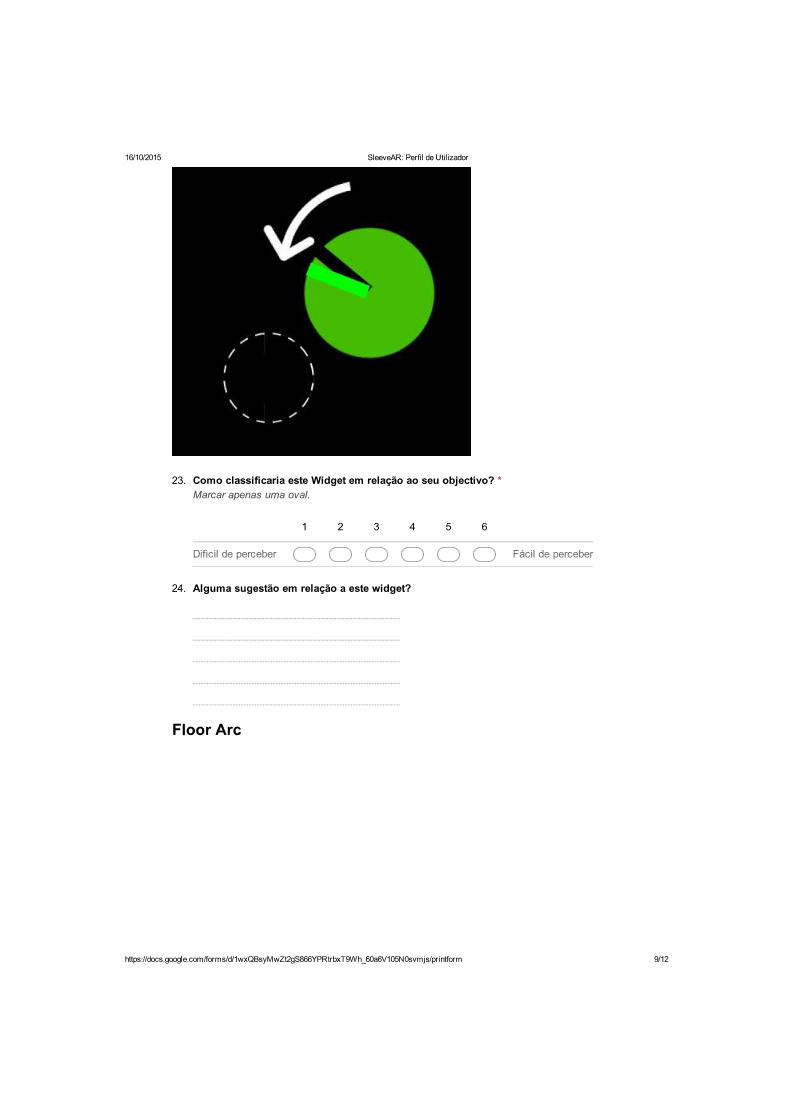
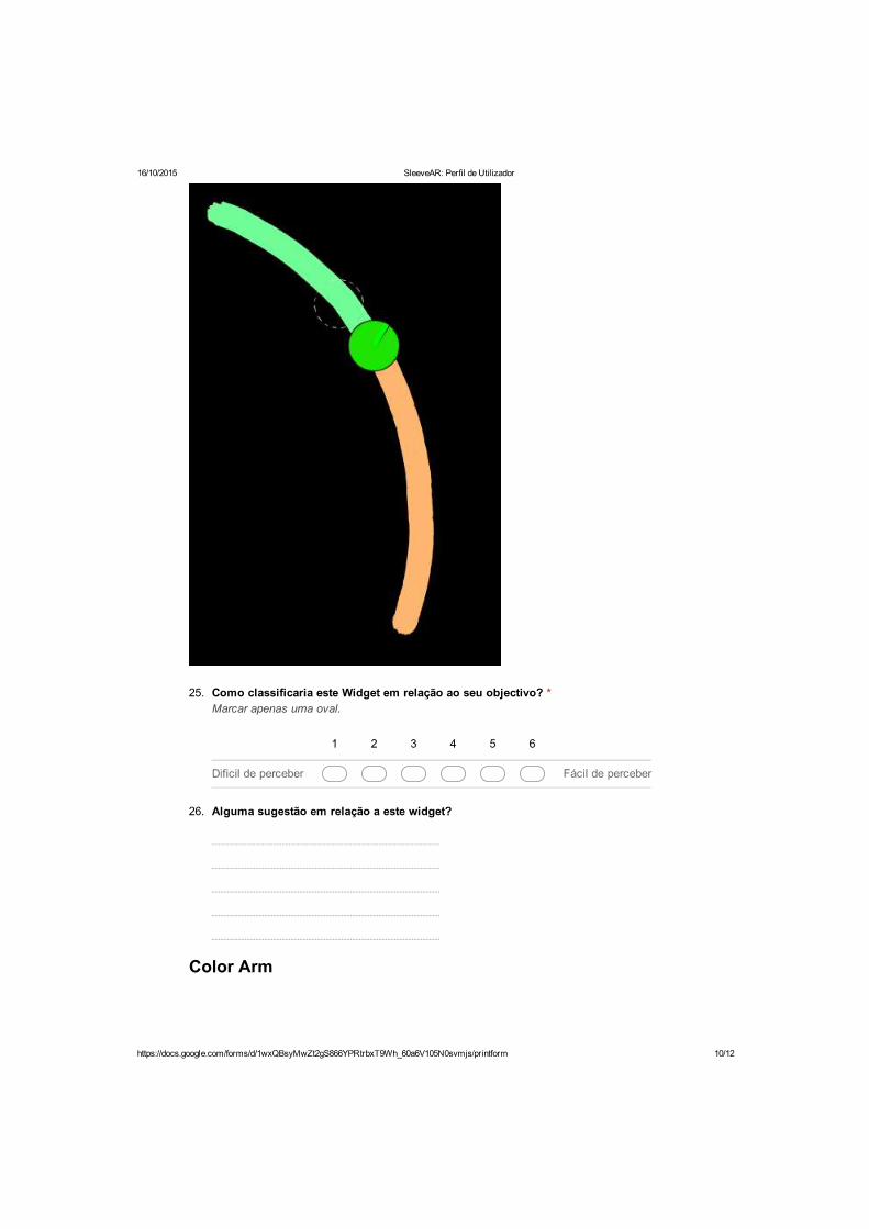
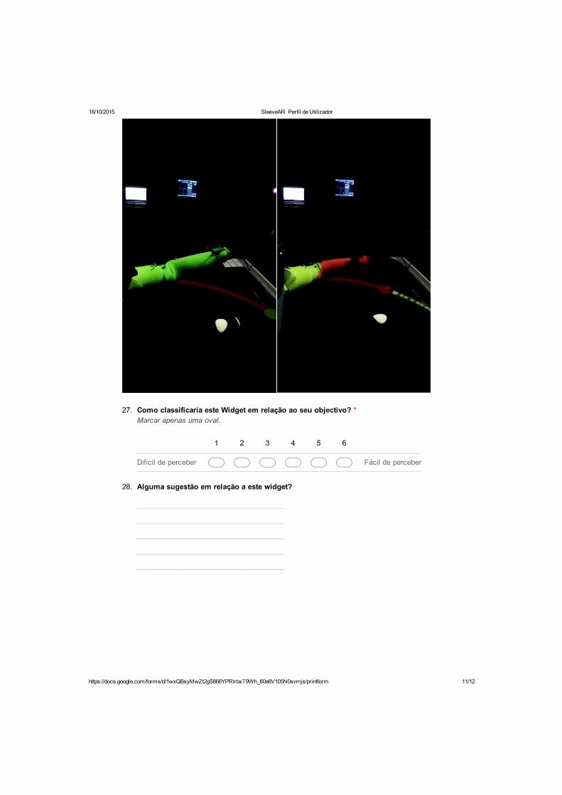


76 APPENDIX B. USER PREFERENCES
B.2 Answers from the Questionnaire

B.2. ANSWERS FROM THE QUESTIONNAIRE 77
Users
It was easy to... 1 2 3 4 5 6 7 8 9 10 11 12 13 14 15 16 17 18
...perform the first exercise? 5 5 6 6 6 6 6 6 6 6 6 6 6 6 6 6 6 6
...perform the second exercise? 4 4 4 5 5 5 6 6 6 6 6 6 6 6 6 6 6 6
...perform the third exercise? 3 4 4 4 5 5 5 5 5 6 6 6 6 6 6 6 6 6
...perform the fourth exercise? 4 5 5 5 5 5 5 5 5 6 6 6 6 6 6 6 6 6
...perform the fifth exercise? 3 3 3 4 4 4 5 5 5 5 5 6 6 6 6 6 6 6
...follow the guidance information? 4 4 4 5 5 5 5 5 5 5 5 6 6 6 6 6 6 6
...see if the arm was in the right position? 2 3 3 4 4 4 5 5 5 5 5 6 6 6 6 6 6 6
..see if the arm was in the wrong position? 2 3 3 3 4 4 5 5 6 6 6 6 6 6 6 6 6 6
...see when the exercise ended? 4 4 5 5 5 5 5 5 6 6 6 6 6 6 6 6 6 6
Table B.1: Answers regarding video observation
Users
It was easy to... 1 2 3 4 5 6 7 8 9 10 11 12 13 14 15 16 17 18
...perform the first exercise? 5 5 5 5 5 5 6 6 6 6 6 6 6 6 6 6 6 6
...perform the second exercise? 4 4 5 5 5 5 5 5 5 6 6 6 6 6 6 6 6 6
...perform the third exercise? 3 3 4 4 4 4 4 5 5 5 5 6 6 6 6 6 6 6
...perform the fourth exercise? 2 3 3 4 4 4 4 5 5 5 5 5 6 6 6 6 6 6
...perform the fifth exercise? 2 2 3 3 3 4 4 4 4 4 4 5 5 5 5 6 6 6
...follow the guidance information? 3 4 4 4 4 4 5 5 5 5 5 5 5 5 6 6 6 6
...see if the arm was in the right position? 3 3 4 4 4 5 5 5 5 6 6 6 6 6 6 6 6 6
..see if the arm was in the wrong position? 4 4 5 5 5 5 6 6 6 6 6 6 6 6 6 6 6 6
...see when the exercise ended? 4 4 5 5 5 5 5 5 5 5 5 6 6 6 6 6 6 6
Table B.2: Answers regarding SleeveAR


![Virtual Reality–Augmented Rehabilitation for Patients ... Ther. 2002;82:898–915.] Key Words: Motor learning, Recovery, Rehabilitation, Stroke, Virtual reality. Alma S Merians,](https://img.pdfslide.us/doc/110x75/5b0847f57f8b9a56408e4436/virtual-realityaugmented-rehabilitation-for-patients-ther-200282898915.jpg)


![State of Augmented Reality, Virtual Reality and Mixed Reality · State of Augmented Reality, Virtual Reality and Mixed Reality [Microsoft Hololen] [Ready Player One] Augmented Reality](https://img.pdfslide.us/doc/110x75/5f82ab6da2d89130b90d78c7/state-of-augmented-reality-virtual-reality-and-mixed-reality-state-of-augmented.jpg)