Embed Size (px)
Citation preview
Video 02: ASSEMBLING of ADAPTER SLEEVE under self-aligningBALL BEARING with HYDRAULIC NUT
See the step-by-step procedure at www.bgl.com.br/en/treinamento.htmTechnical Videos – Video 02
BGL ApplicationEngineering
Instructions for Assembling and DisassemblingSleeves under Self-aligning Bearings with TaperedBoreSleeve for Bearings
Video 02: ASSEMBLING of ADAPTER SLEEVE under self-aligningBALL BEARING with HYDRAULIC NUT
BGL Application Engineering2
Contents:
Initial Arrangements 03
Assembling Procedures 04
. . . . . . . . . . . . . . . . . . . . . . . . . . . . . . . . . . . . . . . . . . . . . . . . . . .
. . . . . . . . . . . . . . . . . . . . . . . . . . . . . . . . . . . . . . . . . . . . . . .
Video 02: ASSEMBLING of ADAPTER SLEEVE under self-aligningBALL BEARING with HYDRAULIC NUT
BGL Application Engineering3
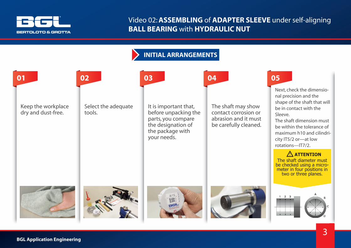
Keep the workplace dry and dust-free.
Select the adequate tools.
It is important that, before unpacking the parts, you compare the designation of the package with your needs.
The shaft may show contact corrosion or abrasion and it must be carefully cleaned.
INITIAL ARRANGEMENTS
01 02 03 04 05Next, check the dimensio-nal precision and the shape of the shaft that will be in contact with the Sleeve.The shaft dimension must be within the tolerance of maximum h10 and cilindri-city IT5/2 or—at low rotations—IT7/2.
ATTENTIONThe shaft diameter must
be checked using a micro-meter in four positions in
two or three planes.
Video 02: ASSEMBLING of ADAPTER SLEEVE under self-aligningBALL BEARING with HYDRAULIC NUT
BGL Application Engineering4
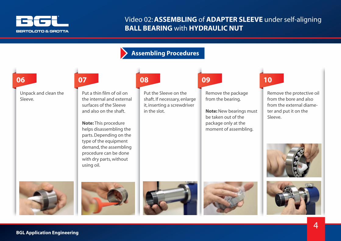
Unpack and clean the Sleeve.
Put a thin film of oil on the internal and external surfaces of the Sleeve and also on the shaft.
Note: This procedure helps disassembling the parts. Depending on the type of the equipment demand, the assembling procedure can be done with dry parts, without using oil.
Put the Sleeve on the shaft. If necessary, enlarge it, inserting a screwdriver in the slot.
Remove the package from the bearing.
Note: New bearings must be taken out of the package only at the moment of assembling.
Remove the protective oil from the bore and also from the external diame-ter and put it on the Sleeve.
Assembling Procedures
06 07 08 09 10
Video 02: ASSEMBLING of ADAPTER SLEEVE under self-aligningBALL BEARING with HYDRAULIC NUT
BGL Application Engineering5
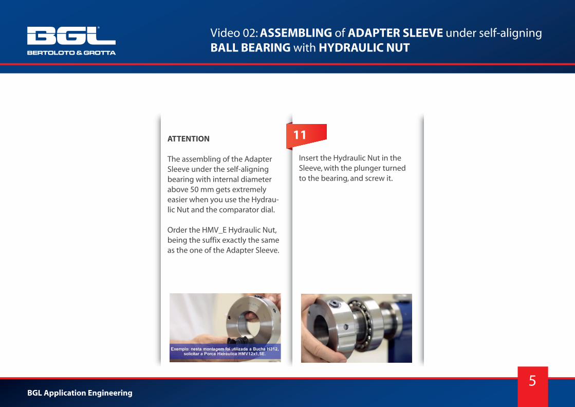
ATTENTION
The assembling of the Adapter Sleeve under the self-aligning bearing with internal diameter above 50 mm gets extremely easier when you use the Hydrau-lic Nut and the comparator dial.
Order the HMV_E Hydraulic Nut, being the suffix exactly the same as the one of the Adapter Sleeve.
Insert the Hydraulic Nut in the Sleeve, with the plunger turned to the bearing, and screw it.
11
Video 02: ASSEMBLING of ADAPTER SLEEVE under self-aligningBALL BEARING with HYDRAULIC NUT
BGL Application Engineering6
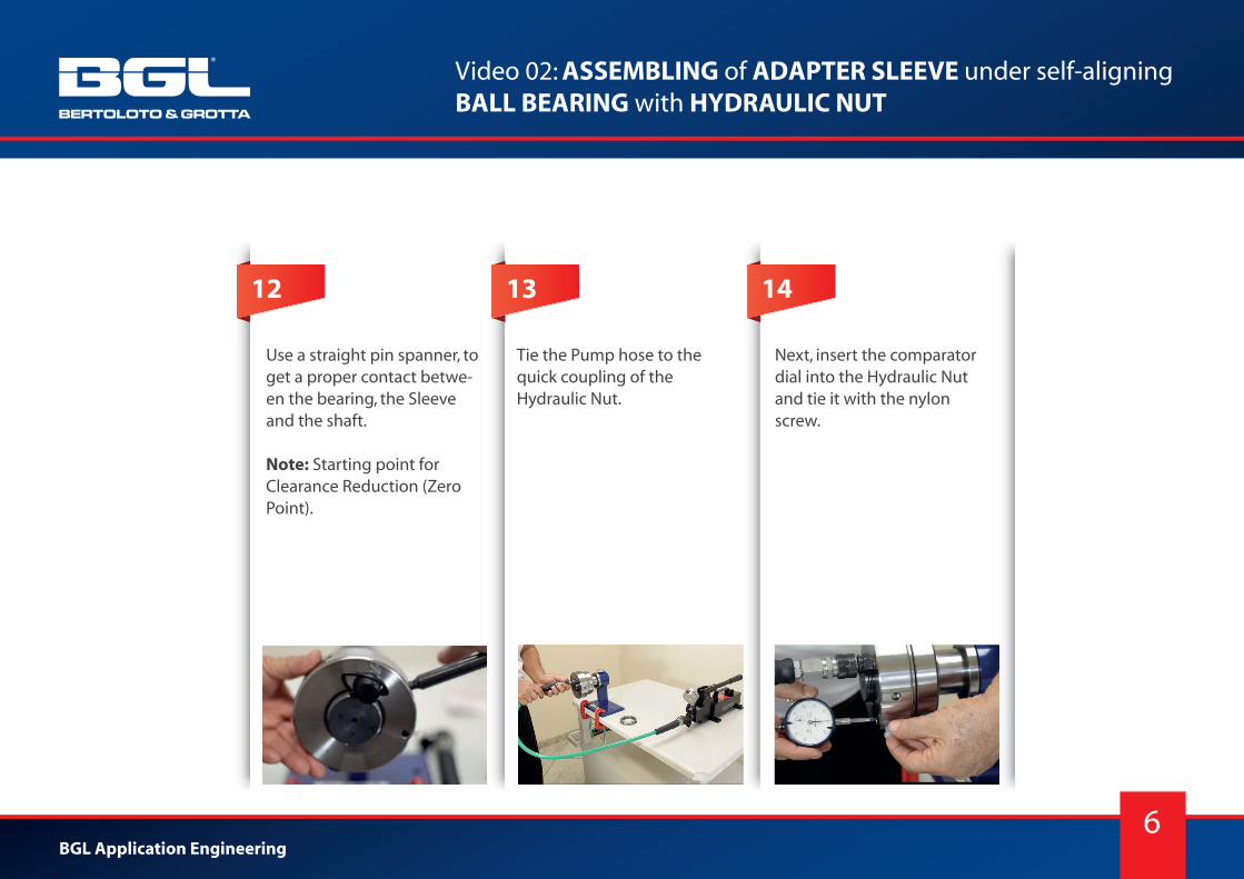
Use a straight pin spanner, to get a proper contact betwe-en the bearing, the Sleeve and the shaft.
Note: Starting point for Clearance Reduction (Zero Point).
Tie the Pump hose to the quick coupling of the Hydraulic Nut.
Next, insert the comparator dial into the Hydraulic Nut and tie it with the nylon screw.
12 13 14
Video 02: ASSEMBLING of ADAPTER SLEEVE under self-aligningBALL BEARING with HYDRAULIC NUT
BGL Application Engineering7
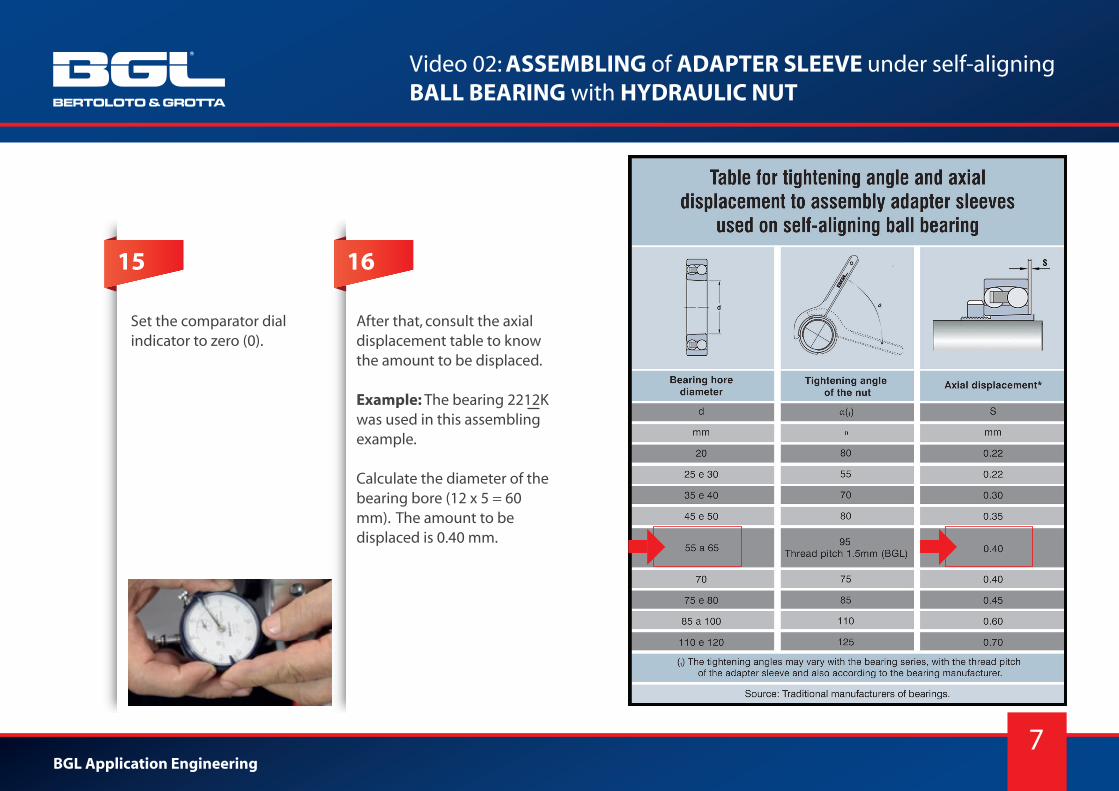
Set the comparator dial indicator to zero (0).
After that, consult the axial displacement table to know the amount to be displaced.
Example: The bearing 2212K was used in this assembling example.
Calculate the diameter of the bearing bore (12 x 5 = 60 mm). The amount to be displaced is 0.40 mm.
15 16
Video 02: ASSEMBLING of ADAPTER SLEEVE under self-aligningBALL BEARING with HYDRAULIC NUT
BGL Application Engineering8
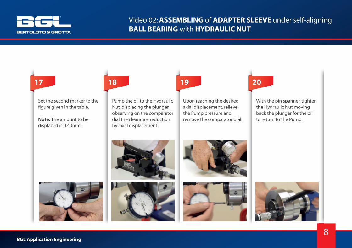
Set the second marker to the figure given in the table.
Note: The amount to be displaced is 0.40mm.
17
Pump the oil to the Hydraulic Nut, displacing the plunger, observing on the comparator dial the clearance reduction by axial displacement.
Upon reaching the desired axial displacement, relieve the Pump pressure and remove the comparator dial.
With the pin spanner, tighten the Hydraulic Nut moving back the plunger for the oil to return to the Pump.
18 19 20

Video 02: ASSEMBLING of ADAPTER SLEEVE under self-aligningBALL BEARING with HYDRAULIC NUT
BGL Application Engineering9
Disconnect the Pump and remove the Hydraulic Nut.
Note: Make sure the bearing has not moved.
Put the MB Lockwasher. Tighten the Locknut firmly using the HN Hook Spanner.
Align the nearest notch of the Nut with the external jut of the Washer and, with the help of a pricker, bend it.
To finish, make sure the bearing can be turned easily with your hands.
Note: It shows some resistance when misalig-ned.
21 22 23 24 25

To disassemble, see Video 13 at www.bgl.com.br/en/treinamento.htm
TR TRAINING KITPractical and dynamic training which helps salespeople and technical staff in their learning.
With the TR KIT you can take your training where you want and as many times as you want.
TR-BGL Kit product available for sale. Consult your distributor.
For more information, see:
Complete Electronic Catalog:www.bgl.com.br/en/catalogo
Assembling Instructions:www.bgl.com.br/en/treinamento.htm
Online Reduction Calculation:www.bgl.com.br/en/calculo_reducao
Catalog Download:www.bgl.com.br/en/catalogos-folders.htm
Reference Technical Standards:ABNT NBR 16535-1: SLEEVES FOR BEARINGS
ABNT NBR 16535-2: LOCKNUTS AND LOCKWASHERS
BGL - Bertoloto & Grotta Ltda Av. Major José Levy Sobrinho, 1296CEP 13486-190 | Limeira – SP | BrasilPhone +55 19 [email protected]/bglbuchaswww.bgl.com.brISO 9001 | since 1957
Sleeve for Bearings