Embed Size (px)
Citation preview

•Additional Instructions
Addition to manual instructionsRef. 110.11
UM
RA
4087
8 -
Rev
. 0

1 / 13
Additional Instructions to the Installation, Operation and
Maintenance Manual of motors W22X
1. Motors equipped with partial discharge monitoring
2. Motors with sleeve bearings
3. Motors with internal bearing temperature probes
4. Power Terminal Box rotation procedure for motors with
Un>6,6kV
Note: Take notice that these addition instructions is only applicable to
specific options that may be not installed total or partial in this
motor.

2 / 13
1. Motors equipped with partial discharge monitoring
The terminal box that contains the BNC jacks/terminal board for sampling with IRIS
portable equipment TGA-B (Not in our scope of supply) is easy to identify because it
has an identification plate with the following design:
Figure 1 – Sampling Terminal Box Identification Plate
After identifying the correct terminal box as described above please ensure that gas
or vapour is not present and is not expected to be present, in quantities which may
give rise to flammable concentrations, during the sampling period. All work shall follow
the safety measures described on IEC60079-14 (See below extract - Safety Measures
for Explosive Gas Atmospheres) and other applicable local standards or guidelines.
Steps for removing the terminal box cover
If all the above conditions are met please proceed as below:
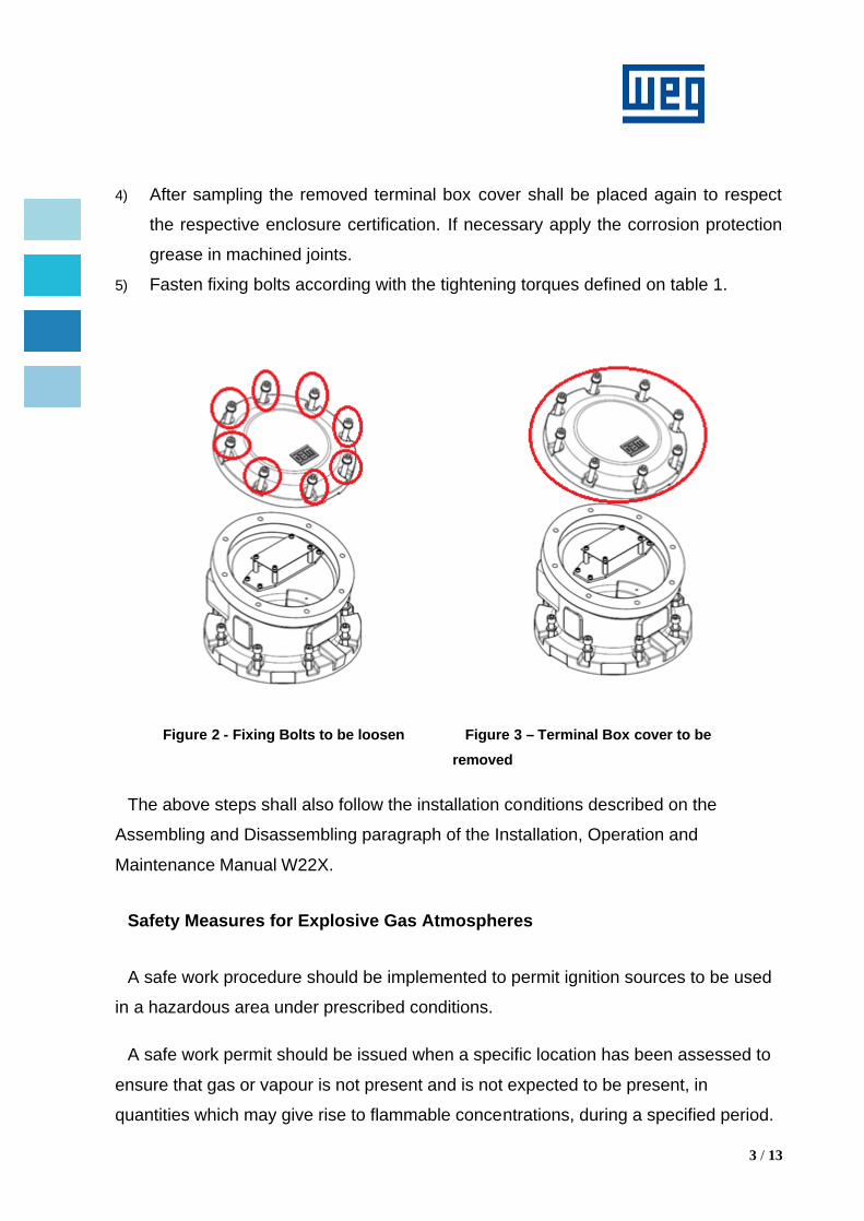
1) Loose the below highlighted fixing bolts (See Figure 2), and set safely aside for
later use.
2) Remove the terminal box cover (See Figure 3), and set safely aside for later use.
3) Proceed with sampling following the instructions described in IRIS portable
equipment manual.
3 / 13
4) After sampling the removed terminal box cover shall be placed again to respect
the respective enclosure certification. If necessary apply the corrosion protection
grease in machined joints.
5) Fasten fixing bolts according with the tightening torques defined on table 1.
Figure 2 - Fixing Bolts to be loosen Figure 3 – Terminal Box cover to be removed
The above steps shall also follow the installation conditions described on the
Assembling and Disassembling paragraph of the Installation, Operation and
Maintenance Manual W22X.
Safety Measures for Explosive Gas Atmospheres
A safe work procedure should be implemented to permit ignition sources to be used
in a hazardous area under prescribed conditions.
A safe work permit should be issued when a specific location has been assessed to
ensure that gas or vapour is not present and is not expected to be present, in
quantities which may give rise to flammable concentrations, during a specified period.

4 / 13
The permit should prescribe continuous or periodic gas monitoring and/or detailed
actions to be taken in the event of a release.
Considerations for the issue of a safe work permit may include:
• Specifying the start date/time of the permit,
• Defining the location of the activity,
• Specifying the nature of the permitted activity (e.g. Diesel generator, drilling),
• Taking and possible recording measurements to confirm the absence of an
ignitable concentration of any flammable gas or vapour,
• Specifying sampling requirements to confirm the continued absence of a
flammable gas or vapour,
• Control of possible flammable gas or liquid sources,
• Specifying contingency plans for emergencies,
• Specifying the expiry date/time out of the permit
Important Notes:
- All of these operations shall only be carried out by trained personnel as per
IEC60079-14 and other applicable local standards or guidelines.
Tightening torques (for Ex d enclosures):
Torque (Nm)
Type Class 8,8 Class 12,9 Class A2 - 70
M8 25 41 17
M10 49 83 34
M12 86 145 57
M14 135 230 91
M16 210 355 141
M18 290 485 195
M20 410 690 274
M22 550 930 372
M24 710 1200 474
Table 1 - Tightening torques
5 / 13
2. Motors with sleeve bearings
Sleeve bearing configuration is available only for W22X motors, classified as
equipment for gases of Group IIB and I M2 with horizontal mounting form on both
drive and non drive-end.
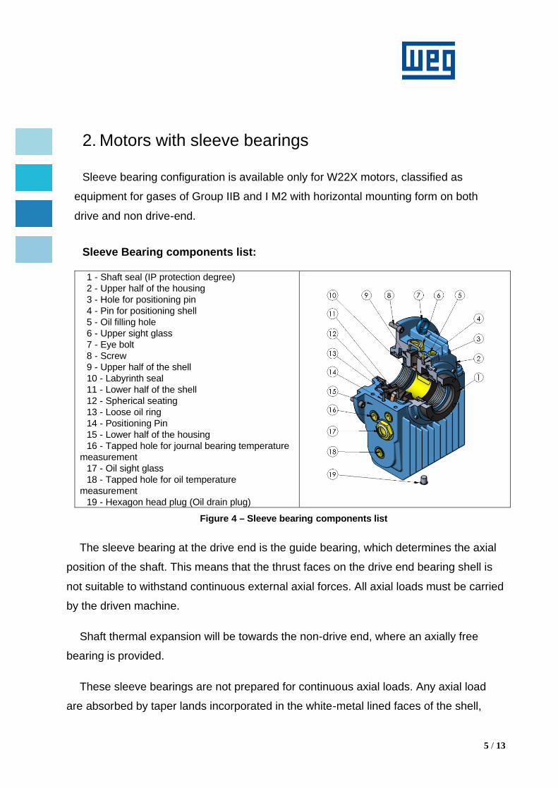
Sleeve Bearing components list:
1 - Shaft seal (IP protection degree) 2 - Upper half of the housing 3 - Hole for positioning pin 4 - Pin for positioning shell 5 - Oil filling hole 6 - Upper sight glass 7 - Eye bolt 8 - Screw 9 - Upper half of the shell 10 - Labyrinth seal 11 - Lower half of the shell 12 - Spherical seating 13 - Loose oil ring 14 - Positioning Pin 15 - Lower half of the housing 16 - Tapped hole for journal bearing temperature
measurement 17 - Oil sight glass 18 - Tapped hole for oil temperature
measurement 19 - Hexagon head plug (Oil drain plug)
Figure 4 – Sleeve bearing components list
The sleeve bearing at the drive end is the guide bearing, which determines the axial
position of the shaft. This means that the thrust faces on the drive end bearing shell is
not suitable to withstand continuous external axial forces. All axial loads must be carried
by the driven machine.
Shaft thermal expansion will be towards the non-drive end, where an axially free
bearing is provided.
These sleeve bearings are not prepared for continuous axial loads. Any axial load
are absorbed by taper lands incorporated in the white-metal lined faces of the shell,

6 / 13
which would be damaged under a continuous load, causing overheating and bearing
collapse.
In the motor design the rotor is not self-aligned and it has a maximum axial play of
±3mm from the mechanical center (Figure 5). The mechanical center is the midpoint
between the rotor end floats limits.
The rotor axial center position must be assured by the driven machine/coupling. This
must be taken into consideration during the assembly of the motor together with driven
machine.
The rotor center axial position is indispensable to ensure the correct continuous
functioning of the motor, without axial continuous load applied to the drive end sleeve
bearing.
Figure 5 – Axial End Float
WEGeuro electric motors equipped with self-lubrication sleeve bearings are shipped
and transported without oil in the sleeve bearings.
Before the motor startup, the customer must fill the sleeve bearings with the oil and
quantity shown in the Table 1, and verify the oil level at the Oil sight glass (component
17).
7 / 13
Customer must, also, respect the lubrication interval of the motor. To replace the oil,
proceed as follows:
1) Drain the oil through the drain hole located at the bottom of the bearing
(component 19);
2) Close the oil drain hole;
3) Remove the oil inlet plug (component 5);
4) Fill the sleeve bearing with the specified oil and with the amount of oil specified in;
5) Check the oil level and ensure it is kept close to the center of the sight glass
(component 17);
6) Install the oil inlet plug;
7) Check for oil leaks;
8) NDE-bearing: oil inlet and outlet have extended pipes to access without removing
fan cover.
Oil specifications of sleeve bearings for W22X motor range:
Poles Frame Size
Lubrication Method
Sleeve Bearing
Lubricant Specification
Lubrication interval (hours)
Oil Quantity (liters)
Viscosity Range
ISO 40ºC SSU 100ºF
2P
315L
Self-Lubrication
9-80 Mineral Oil ISO VG32
8000
2.8 28.8 - 35.2 [cSt]
137 - 164 [s]
355ML 355AB 400LJ 400G
450KH 500KH
4P+
315L
11-110 Mineral Oil ISO
VG46 4.7
41.4 - 50.6 [cSt]
193 - 235 [s]
355ML 355AB 400LJ 400G
450KH 11-125 500KH
Table 2 – Oil specifications of sleeve bearings
All the instructions for maintenance of sleeve bearings are available on Sleeve
Bearing’s Manufacturer Instructions and Operating Manual.

8 / 13
3. Motors with internal bearing temperature probes
When motor is equipped with total internal bearing temperature probes, the internal
connections are as indicated in Figure 6.
Figure 6 – Internal bearing temperature probes
Steps for removing the endshield
Before removing the endshields it becomes necessary to disconnect the probes, in
order to avoid the rupture of the bearing probe cable.
1) Pull the endshield slightly and carefully (see figure 7) .
Figure 7 -Removing endshield
Bearing probe cable
Motor Endshield
Terminal Box internal access
9 / 13
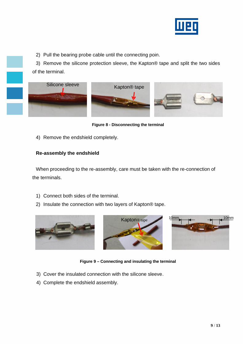
2) Pull the bearing probe cable until the connecting poin.
3) Remove the silicone protection sleeve, the Kapton® tape and split the two sides
of the terminal.
Figure 8 - Disconnecting the terminal
4) Remove the endshield completely.
Re-assembly the endshield
When proceeding to the re-assembly, care must be taken with the re-connection of
the terminals.
1) Connect both sides of the terminal.
2) Insulate the connection with two layers of Kapton® tape.
Figure 9 – Connecting and insulating the terminal
3) Cover the insulated connection with the silicone sleeve.
4) Complete the endshield assembly.
Kapton® tape Silicone sleeve
Kapton® tape 10mm 10mm

10 / 13
4. Power Terminal Box rotation procedure for motors
with Un>6,6kV (only possible by costumer request
during the order)
For motors equipped with Power Terminal Box –PTB, located at top of the motor with
cable entries from drive end side.
Figure 10 – Example of Motor with PTB with cable entries from DE side
Procedure to rotate the Power Terminal Box (example for 90º CCW seen from top of PTB):
1) Remove the PTB cover:
a. Unbolt the PTB cover - 8 bolts;
b. Install a magnet in the center of PTB cover;
c. Pull the magnet to remove the PTB cover;
Figure 11 – PTB cover removed
PTB Cover
PTB
Adapter

11 / 13
2) Rotate the PTB with rotate device;
a. Unbolt the PTB – remove the 8 bolts inside terminal box;
Figure 12 – Inside view of PTB.
b. Assemble the rotate device in the top of the terminal box fixing the 6 bolts;
Note: This device is not supplied as standard. WEG can provide it as
option.
c. Turn the PTB 90º to cable entry at right side seen from DE side;
Figure 13 - Turn of the PTB with rotate device
d. Remove the rotate device;
3) Reassemble the PTB
a. Bolt the PTB to the adapter with the 8 bolts (the same bolts that originally
fix the PTB)
4) Assemble the PTB cover:
a. With the lifting device and magnet, slowly down the PTB cover, assuring
that PTB and PTB cover cylindrical joints are centered;

12 / 13
b. Bolt the PTB cover to the PTB with the 8 bolts (the same bolts that
originally fix the PTB cover).
Rotate the PTB can be difficult due to thermal variations of the Power Terminal Box
and Adapter cylindrical joints.
Alternative procedure to rotate the Power Terminal Box (example for 90º CCW seen from top of PTB):
1) Remove the PTB cover:
a. Unbolt the PTB cover - 8 bolts;
b. Install a magnet in the center of PTB cover;
c. Pull the magnet to remove the PTB cover;
2) Loose the PTB:
a. Unbolt the PTB – remove the 8 bolts inside terminal box;
b. Fix two eyebolts in the fixing holes of the terminal box;
c. Clamp the lifting device in the two eyebolts;
d. Lift the PTB 60mm, keeping always horizontal.
Figure 14 - PTB lifted.
13 / 13
3) Rotate the PTB:
a. Carefully rotate the PTB, always horizontal levelled, 90º CCW seen from
top of PTB.
4) Reassemble the PTB:
a. Slowly down the PTB, assuring that PTB and adapter cylindrical joints are
centered;
b. With the PTB settled in the adapter;
c. Bolt the PTB to the adapter with the 8 bolts (the same bolts that originally
fix the PTB)
5) Assemble the PTB cover:
a. With the lifting device and magnet, slowly down the PTB cover, assuring
that PTB and PTB cover cylindrical joints are centered;
b. Bolt the PTB cover to the PTB with the 8 bolts (the same bolts that
originally fix the PTB cover).


![Cable reduction sleeve - Glenair, Inc. · Reduction Sleeve for use with Mechanical Cable Clamp or Basketweave Cable Grip Shell Size Sleeve P/N Sleeve inner diameter [mm] Sleeve outer](https://img.pdfslide.us/doc/110x75/5ec496aef7ac3c7f406c6755/cable-reduction-sleeve-glenair-inc-reduction-sleeve-for-use-with-mechanical.jpg)