Embed Size (px)
Citation preview

Page 1/17
Synthesis of CA6/AlON Composites with EnhancedSlag ResistanceYunsong Liu
University of Science and Technology BeijingEnhui Wang
University of Science and Technology BeijingLinchao Xu
University of Science and Technology BeijingTao Yang
University of Science and Technology BeijingXinmei Hou ( [email protected] )
University of Science and Technology BeijingZhijun He
University of Science and Technology LiaoningTongxiang Liang
JiangXi University of Science and Technology
Research Article
Keywords: CA6/AlON composite, two-step method, slag resistance
Posted Date: February 5th, 2021
DOI: https://doi.org/10.21203/rs.3.rs-184922/v1
License: This work is licensed under a Creative Commons Attribution 4.0 International License. Read Full License

Page 2/17
AbstractAiming to improve the slag resistance of calcium hexaaluminate (CA6), different amounts of AlON havebeen introduced into CA6 using two approaches, i.e. one-step and two-step methods. The results showthat both the two phases of CA6 and AlON are uniformly distributed when sintered at 1650 °C for 2 h in�owing nitrogen using two-step method. The optimized amount of AlON addition is determined to be 10wt%. In addition, the reaction test method is performed and CA6/AlON composite exhibits much betterslag penetration and corrosion resistance compared with pure CA6. The effect of AlON is also discussed.
1 IntroductionCalcium hexaaluminate (CaAl12O19, usually denoted as CA6) is of great interest as high temperatureceramics bene�ting from the combination of excellent properties including high melting point, goodalkaline resistance, high stability in a reducing atmosphere, and low thermal conductivity, and so on [1–4]. However, CA6 possesses a magnetoplumbite structure and belongs to hexagonal crystal system(space group P63/mmc) [5–7]. This speci�c structure tends to result in the anisotropic growth of CA6
grains forming the platelet shape, which is harmful to the sintering of CA6. As a result, the obtained CA6
usually possess more than 20% porosity even sintered at the temperature up to 1750°C [8, 9]. Thisstructure accelerates the penetration and corrosion rate of molten slag when used as furnace lining andthus greatly limits the practical application [10, 11].
It is well known that the addition of second phase is a practicable approach to increase the densi�cationof matrixes during the sintering process [11–15]. For instance, Yao et al. [13] introduced 20wt% SiO2 intoCr2O3 during the sintering process in a buried carbon atmosphere. The results showed that the crystalgrowth of Cr2O3 is signi�cantly limited and the densi�cation of bulk composites is increased to a largeextent. Luo et al. [14] put forward that MnO2 can improve the densi�cation of Ca2Mg2Al28O46 ceramicand the apparent porosity is decreased to 8.4% with 3 wt% MnO addition. Xu et al. [11, 15] found thatZrO2 and TiO2 can greatly decrease the porosity and pore sizes of MgAl2O4-CaAl4O7-CaAl12O19
composite, thereby improving the slag resistance of the composite.
Al23O27N5 (usually denoted as AlON) as a solid solution of Al2O3 and AlN belongs to cubic crystal system(space group Fd-3m) [16]. Different from CA6 in the shape of plate with a relatively big size, AlON alwaysexists in small cubic or near-spheroidal structures. The speci�c structure of AlON makes it possible to �llthe voids forming among CA6 grains. Meanwhile, AlON possesses the characteristics of nitrogen oxideand it has poor wettability with metal and oxide melts [16–20]. It has been reported that AlON as theadditive can improve the slag resistance of the matrix [21, 22]. Furthermore, there is no signi�cant solidsolution between CA6 and AlON even sintered at 1750°C, which is conducive to the maintenance ofrespective excellent characteristics [23]. Based on this, it is reasonably to anticipate that AlON should be apromising candidate for the improvement of densi�cation and slag resistance of CA6.

Page 3/17
In this study, CA6/AlON composites have been prepared using both one-step method and two-stepmethod for the �rst time. The former is directly sintered using Al2O3, CaCO3 and Al with different ratio asraw materials in nitrogen. The latter consisting of the pre-synthesized CA6 and AlON is sintered at 1650℃. The obtained CA6/AlON composites were characterized using XRD, SEM combined with EDS. Thebulk density and apparent porosity were also measured. Based on this, the slag penetration and corrosionresistance of CA6/AlON composites was carried out. The same experiment was also conducted usingpure CA6 as the control group. The effect of AlON on the slag resistance of CA6/AlON composites wasalso discussed.
2 Experimental Procedure
2.1. Raw materialsThe main raw materials used in this work were analytically pure Al2O3, CaCO3, MgO and SiO2 powders(Sinopharm Chemical Reagent Co., Ltd., 99 wt% purity, average grain size < 44 µm), together with Al �nepowders (Shanghai Aladdin Reagent Co., Ltd., 99 wt% purity, average grain size 58 µm). Aiming toguarantee the validity for synthetic samples, Al2O3, SiO2 and MgO powders before use were calcined to1000 ℃ for 1 h in a mu�e furnace to remove the absorbed water and bound water.
2.2. Preparation of CA6/AlON composites
2.2.1 One-step methodIn view of one-step method, the pre-�red Al2O3 and CaCO3 powders as well as Al powder with differentproportions were wet ball-milled for 24 h using absolute ethanol as medium. The resulting slurry wasdried in a vacuum drying cabinet at 100 ℃ for 12 h, grounded in a mortar, and �ltrated through nylonsieves with the screen mesh of 120. Subsequently, the obtained mixture was pressed under 20 MPa into25 mm × 25 mm cylinders. Finally, the specimens were sintered at the temperature range from 1650°C to1750°C for 3 h under �owing nitrogen atmosphere.
2.2.2 Two-step methodAs for two-step method, it mainly includes the preparation of single CA6 and AlON phases and thesintering process of CA6/AlON composites. Regarding the preparation of AlON phase, aluminothermicreduction nitridation method was herein adopted [24–26]. Firstly, the pre-�red Al2O3 and Al powders wereweighed at a mass ratio of 88:12. Then the mixture was wet milled for 24 h and dried in vacuum at 100℃ for 10 h. Afterwards, the dried powder mixture was pressed into a 50 mm block under a pressure of 30MPa and then sintered at 1750°C in a graphite crucible for 3 h under �owing N2 atmosphere. Eventually,the AlON ceramic block was pulverized using 200–300 mesh to obtain AlON powder for later use.Likewise, the single CA6 phase was also prepared using pre-�red Al2O3 and CaCO3 as raw materials andsintered at 1550 ℃ for 2 h in air. The resulting CA6 block was further crushed to obtain CA6 powders with

Page 4/17
similar size range as AlON powder. During the synthetic process of CA6/AlON composite, AlON and CA6
powders obtained above were further mixed, ball milled, dried, pressed, and then sintered at 1650°C for 2h in �owing nitrogen atmosphere.
It should be pointed out that the amount of AlON incorporated during the above two methods were 5 wt%,10 wt%, 15 wt% and 20 wt%. For simplicity, CA6/AlON composites prepared by one-step method and two-step method were named as SI-x and SII-x respectively, where x denotes the amount of AlON as shown inTable 1.
Table 1Composition of the designed CA6/AlON composites (wt%).
Composites prepared by one-stepmethod
Composites prepared by two-stepmethod
CA6 AlON
SI-5 SII-5 95 5
SI-10 SII-10 90 10
SI-15 SII-15 85 15
SI-20 SII-20 80 20
2.3. Slag penetration and corrosion testThe reaction test method as shown in Fig. 1 was adopted to evaluate the slag penetration and corrosionresistance of CA6/AlON composites [10, 11, 27]. This method has two main purposes. One is to assessthe wettability between the molten slag and the matrix. The second is to provide an intuitive way toobserve the coupled penetration and corrosion effect of molten slag on the matrix. Herein, the typicalre�ning ladle slags as illustrated in Table 2 were pressed into cylinders with 30 mm in diameter and 5 mmin height. The slag cylinders were then put on the polished surfaces of CA6/AlON composite and pure CA6
matrixes with approximate 30 mm in height respectively, followed by the reaction test in a chamberelectric furnace with carbon buried at 1550 ℃ for 0.5 h. After cooled down to room temperature, theywere cut perpendicularly to the slag-matrix interface and polished. The dimensional changes of CA6/AlONcomposite and pure CA6 matrixes before and after the reaction test and the penetration depth of the slagwere evaluated.
Table 2Chemical composition of model slag (wt%).
Oxides CaO Al2O3 SiO2 MgO C/S
Contents 59.1 19.3 17.3 4.3 3.42

Page 5/17
2.4. CharacterizationThe crystalline phases of the synthesized samples were examined by the X-ray diffraction (XRD) analyzer(Cu Kα radiation, MAC Science Co. Ltd., Japan) from 10° to 90° at a step of 0.02°. The surface and cross-section morphologies as well as chemical analysis of the samples were characterized by a scanningelectron microscopy (SEM, JSM-840A, JEOL, Japan) in combination with energy dispersive X-rayspectrometry (EDS). In addition, the bulk density and apparent porosity were evaluated in terms of theArchimedes law.
3 Results And Discussion
3.1 Preparation and characterization of CA6/AlONcomposites by one-step methodFigure 2 shows the typical XRD patterns of SI-10 prepared by one-step method at different sinteringtemperatures. It can be seen that the main phase of the sample sintered at 1650°C is CA6 with a smallamount of Al2O3 and AlN. When the temperature rises up to 1700°C, new characteristic peakscorresponding to AlON can be observed. Meanwhile, the relative intensities of the characteristic peaks ofAl2O3 are signi�cantly reduced, indicating that higher sintering temperature can enhance the solid-solidreaction of Al2O3 and AlN to form AlON. This phenomenon is well consistent with the results reported inthe literatures [24, 28]. With the sintering temperature further increasing to 1750°C, the main phases of thesintered products transform into CA6 and AlON. The phase evolution for SI-5, SI-15 and SI-20 is almostthe same to SI-10, therefore they are herein not described for brevity.
The fracture morphologies of CA6/AlON composite sintered at 1750°C using one-step method are furtherobserved. The representative SEM images of SI-10 and SI-20 are illustrated in Fig. 3. It can be seen fromFig. 3(a) that the SI-10 are composed of two typical morphologies, i.e. plate structures with relatively bigsize and clusters with relatively small size. Combined with EDS analysis, they are determined to be CA6
and AlON as marked by the red dotted line. The reason for the formation of AlON clusters should beclosely related to the cluster characteristic of Al powders with a low molten point of 659°C. During thesintering process, the liquid Al has bad wettability on Al2O3, so it will tend to aggregate and precipitate onthe surface of Al2O3. Then, these liquid tiny AlN droppings can be further nitridized into �ne AlN particleswith high activity [24, 26]. When the temperature further increases up to the critical point where thereaction between AlN and Al2O3 start to occur, AlON phase is generated in situ and gradually form AlONclusters as marked in Fig. 3. When the amount of AlON is increased up to 20 wt%, the morphology of SI-20 is nearly unchanged, except that more AlON clusters are formed as shown in Fig. 3(b). In addition, itshould be noted that the porosity of CA6/AlON composites is rather high and is not decreased even moreAlON is added. Therefore, it is reasonably to conclude that one-step method is not an appropriateapproach to prepare dense CA6.

Page 6/17
3.2 Preparation and characterization of CA6/AlONcomposites by two-step method
3.2.1 Preparation of single CA6 and AlON phasesFigure 4 illustrates the XRD pattern and fracture SEM image of single CA6 phase sintered at 1550 ℃ for 2h in air. It can be seen from Fig. 4(a) that the predominant peaks correspond well to CA6 phase (JCPDS:No. 76–0665), con�rming the high purity of obtained CA6. In view of the fracture microstructure, CA6
grains exhibit hexagonal plate and porous structure.
XRD and SEM analysis of single AlON phase sintered at 1750 ℃ for 2 h in �owing nitrogen atmosphereare shown in Fig. 5. Figure 5(a) shows that the obtained AlON phase (JCPDS: No. 80-2171) possessesgood crystalline character and high purity. From Fig. 5(b), it can be found that the AlON grains are inrelatively small size and evenly distributed.
3.2.2 Preparation of CA6/AlON compositesCA6/AlON composites with different amounts of AlON addition have been prepared according to theprocedures provided in Sect. 2.2.2 and the corresponding fracture SEM images are shown in Fig. 6. It canbe found from Fig. 6(a) that the grains are evenly distributed in the fracture surface. Combined with theenlarged view (Fig. 6(b)) and EDS analysis, small AlON grains are uniformly distributed around the bigCA6 grains. When the amount of AlON is added up to 10 wt% (Figs. 6(c) and (d)), the porosity in SII-10 isobviously decreased. The newly added AlON should �ll the voids between CA6 grains and thus increasesthe densi�cation. However, the further decrease in porosity is not obvious in SII-15 and SII-20 with moreAlON addition (Figs. 6(e)-(h)). This phenomenon may be attributed to the fact that some excessive AlONgrains can distribute on the surface rather than the voids between CA6 grains, which in turn increases theporosity of the composites.
To quantify the effects of AlON addition on CA6/AlON composites, bulk density and apparent porosityhave been further characterized as depicted in Fig. 7. It can be seen that with the amount of AlONincreasing, the bulk density and apparent porosity gradually increase and decrease, respectively. Besides,the changing trends are much more obvious when AlON addition is below 10 wt%. The bulk density andapparent porosity are 2.26 g∙cm− 3 and 20.2%, respectively. When more AlON is added (SII-15 and SII-20),there are small amplitude of changes especially for apparent porosity. From the above results, theoptimized amount of AlON in CA6/AlON composites is determined to be 10 wt% with the consideration ofrelatively high synthetic cost of AlON. It should be stated that the densi�cation of CA6/AlON compositescan be further increased at higher temperature or using hot pressing. In this work, we mainly focus on thecomposite powder. More work will be carried out in the future.
3.3 Slag penetration and corrosion test

Page 7/17
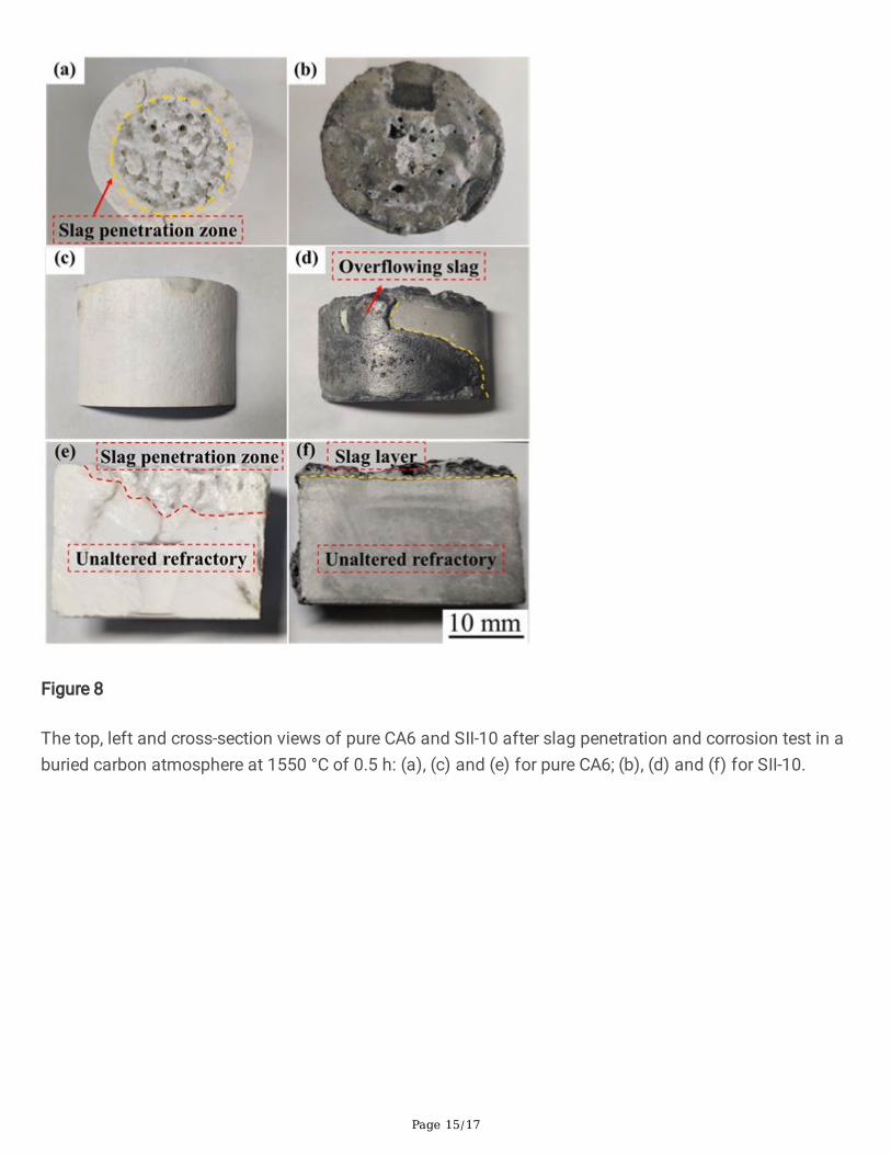
Figure 8 shows the slag penetration and corrosion test results of SII-10 with carbon buried at 1550°C for0.5 h. For comparison, the corresponding test for pure CA6 has also been performed. As shown inFigs. 8(a) and 8(c), the contacting surface between pure CA6 and the slag is completely corroded andpenetrated, with no slag remaining on the upper surface (Fig. 8(e)). By comparison, SII-10 exhibits a badwettability with the molten slag (Fig. 8(b)) and some �owing slag can be observed on the side surface(Fig. 8(d)). This phenomenon should be attributed to the intrinsic character of AlON, which can increasethe interfacial tension between the molten slag and SII-10 and thus increase the wetting angle [16–20]. Inaddition, Fig. 8(f) suggests that there is no slag penetration. A clear slag layer can be seen on the uppersurface of SII-10, indicating the better slag penetration and corrosion resistance.
To further investigate the promoted mechanism of AlON addition on the slag penetration and corrosionresistance, the typical back-scattered electron (BSE) analysis of the cross-sections of pure CA6 and SII-10has been compared as shown in Fig. 9 and Fig. 10, respectively. Figure 9(a) shows the EDS maps for thecross sections of pure CA6 after the slag penetration and corrosion test. It can be seen that there is noobvious boundary between the corrosion zone and unaltered matrix. From the enlarged image (Fig. 9(b))in combination with EDS analysis, the corrosion zone is composed of CA6 and CaO∙2Al2O3 (CA2) thatdistribute crossly. The absence of Si and Mg elements is resulted from the relatively low proportions inslag (Table 2), which should exist in the upper part of the corrosion zone. Figure 9(c) shows the unalteredmatrix is CA6 with high porosity. If given more slag and longer testing time, the molten slag is expected tofurther penetrate and corrode with the matrix.
Figure 10 shows the BSE images and corresponding element distributions of cross sections of SII-10after slag penetration and corrosion test. The cross section (Fig. 10(a)) can be clearly divided into threeparts, i.e. slag layer, corrosion zone and unaltered matrix. In view of the slag layer as shown in Fig. 10(b),it is con�rmed by EDS analysis that the darkest areas are pores �lled by carbon. In addition, some low-melting-point phases including CaMgAl2SiO7 (CMAS) and Ca2Al2SiO7 (C2AS) together with some high-melting-point phases consisting of CA and CA2 as well as MgO∙Al2O3 (MA) can be also observed, whichis consistent with the results reported by Chen et al. [1] As for the corrosion zone, the thickness isapproximate 345 µm. The whole phase composition in this zone is similar, i.e. CA2 and C2AS representedby pale and bright areas respectively (Figs. 10(c) and (d)). The differences lie in the following two points.Firstly, there is a gradient distribution of C2AS phase along the corrosion direction. Secondly, CA2 phaseclose to the unaltered matrix is more dense and continuous. These results suggest that CA2 layer caneffectively slow down the penetration of low-point-melting phase and thus hinder the further corrosion.
The reaction between the molten slag and the matrix is a process accompanied with the ion diffusion.According to the ionic structure model for the molten slag [29], the CaO with the highest proportion in theslag used in this work (Table 1) will release a large number of Ca2+ and O2−. In this case, Ca2+ and O2−
have much higher concentration than the other ions and thus they possess faster penetration rate withgreater driving force. On one hand, when CA6 in SII-10 comes into contact with the molten slag, it can
react with Ca2 + and O2− to form CA2 according to Eq. (1). On the other hand, AlON can be oxidized by O2−

Page 8/17
ions to form more Al2O3 (Eq. (2)). These Al2O3 will further react with Ca2 + and O2− to generate CA2 asreferred to Eq. (3). Based on this, the continuous and dense CA2 is gradually form in corrosion zone,which can further improve the slag penetration and corrosion resistance of SII-10.
(1)
(2)
(3)
ConclusionsIn this work, CA6/AlON composites with different amounts of AlON addition have been prepared usingone-step and two-step methods, respectively. The phase distribution using two-step method is far moreuniform. Furthermore, the optimized amount of AlON addition is 10 wt% (SII-10), in which the bulk densityand apparent porosity are 2.26 g∙cm-3 and 20.2%, respectively. In view of the slag penetration andcorrosion test, the addition of AlON decreases the wettability of CA6/AlON composites with the molten
slag to a great extent. In addition, AlON oxidized by O2- ions released from the molten slag can formAl2O3, which can further react with Ca2+ and O2- ions to form dense and continuous CA2 layer. This layercan effectively inhibit the further penetration and corrosion of molten slag.
Declarations
AcknowledgementsYunsong Liu and Enhui Wang contributed equally to this work. This work was supported by the NationalScience Fund for Distinguished Young Scholars (No. 52025041), the National Natural ScienceFoundation of China (No. 51904021, 51974021), and the Fundamental Research Funds for the CentralUniversities (No. FRF-TP-19-008A1, No. FRF-TP-19-004B2Z), the project of Liaoning Province’s“Rejuvenating Liaoning Talents Plan” (XLYC1902092) and Beijing Excellent Talents Foundation for�nancial support.
References1. Chen JH, Chen HY, Mi WJ, et al. Substitution of Ba for Ca in the Structure of CaAl12O19. J Am ceram
Soc 2017, 100: 413-418.
2. Dong BB, Yuan B, Wang G, et al. Fabrication of porous SiC/calcium hexaluminate composites. J EurCeram Soc 2016, 36: 3889-3893.

Page 9/17
3. Xu LC, Wang EH, Hou XM, et al. Effect of incorporation of nitrogen on calcium hexaaluminate. J EurCeram Soc 2020, 40: 6155-6161.
4. Li B, Li GQ, Chen HY, et al. Physical and mechanical properties of hot-press sintering ternary CM2A8
(CaMg2Al16O27) and C2M2A14 (Ca2Mg2Al28O46) ceramics. J Adv Ceram 2018, 7: 229-236.
5. Utsunomiya A, Tanaka K, Morikawa H, et al. Structure re�nement of CaO·6Al2O3. J Solid State Chem1988, 75: 197-200.
�. Domı́nguez C, Chevalier J, Torrecillas R, et al. Microstructure development in calcium hexaluminate.J Eur Ceram Soc 2001, 21: 381-387.
7. Iyi N, Takekawa S, Kimura S. Crystal chemistry of hexaaluminates: β-alumina and magnetoplumbitestructures. J Solid State Chem 1989, 83: 8-19.
�. Salomão R, Ferreira VL, de Oliveira IR, et al. Mechanism of pore generation in calcium hexaluminate(CA6) ceramics formed in situ from calcined alumina and calcium carbonate aggregates. J EurCeram Soc 2016, 36: 4225-4235.
9. Asmi D, Low IM. Physical and mechanical characteristics of in-situ alumina/calcium hexaluminatecomposites. J Mater Sci Lett 1998, 17: 1735-1738.
10. Vázquez BA, Pena P, De Aza AH, et al. Corrosion mechanism of polycrystalline corundum andcalcium hexaluminate by calcium silicate slags. J Eur Ceram Soc 2009, 29: 1347-1360.
11. Xu L, Chen M, Wang N, et al. Corrosion mechanism of MgAl2O4-CaAl4O7-CaAl12O19 composite bysteel ladle slag: effect of additives. J Eur Ceram Soc 2017, 37: 2737-2746.
12. Feng B, Wang Z, Fan Y, et al. Creep deformation behavior during densi�cation of ZrB2-SiBCNceramics with ZrO2 J Adv Ceram 2020, 9: 544-557.
13. Yao SZ, Wang EH, Chen JH, et al. Effectively controlling the crystal growth of Cr2O3 using SiO2 as thesecond phase. J Am ceram Soc 2019, 102: 2187-2194.
14. Luo Q, Gu H, Fang Y, et al. Enhancement of the densi�cation and thermal properties ofCa2Mg2Al28O46 ceramic by MnO addition. Ceram Int 2020, 46: 18734-18741.
15. Xu L, Chen M, Jin LY, et al. Effect of ZrO2 addition on densi�cation and mechanical properties ofMgAl2O4-CaAl4O7-CaAl12O19 J Am Ceram Soc 2015, 98: 4117-4123.
1�. Corbin ND. Aluminum oxynitride spinel: A review. J Eur Ceram Soc 1989, 5: 143-154.
17. Zhong X, Zhao H. High-temperature properties of refractory oxide-nonoxide composites. China’sRefract 1999, 8: 3-8.
1�. Hong Y, Li Y, Tong SH, et al. Effect of the addition of Al powder on the microstructure and phaseconstitution of magnesia-spinel composites sintered at 1800 °C in N2. Key Engineering Materials2016, 697: 345-349.
19. Takeda K, Hosaka T. Characteristics of new raw material alon for refractories. Interceram 1989, 38:18-22.

Page 10/17
20. Ma C, Li Y, Jiang P, et al. Formation mechanism of γ-AlON and β-SiC reinforcements in a phenolicresin-bonded Al-Si-Al2O3 composite at 1700 °C in �owing N2. J Mater Sci 2020, 55: 5772-5781.
21. Murakami K, Iwasaki A, Akatsuka Y, et al. One results of sliding nozzle refractories using aluminumoxynitride. Taikabutsu
22. Hosaka T, Kato M. A study of compositional modi�cation of trough mixture by using aluminumoxinitride. Refractories 1985, 37: 22-26.
23. Sun WY, Yen TS. Phase relationships in the system Ca-Al-O-N. Mater Lett 1989, 8: 150-152.
24. Zhang N, Liang B, Wang XY, et al. The pressureless sintering and mechanical properties of AlONceramic. Mat Sci Eng-A 2011, 528: 6259-6262.
25. Wang Y, Xie X, Qi J, et al. Two-step preparation of AlON transparent ceramics with powdersynthesized by aluminothermic reduction and nitridation method. J Mater Res 2014, 29: 2325-2331.
2�. Su M, Zhou Y, Wang K, et al. Highly transparent AlON sintered from powder synthesized by directnitridation. J Eur Ceram Soc 2015, 35: 1173-1178.
27. Rodríguez-Galicia JL, De Aza AH, Rendón-Angeles JC, et al. The Mechanism of corrosion ofMgOCaZrO3-calcium silicate materials by cement clinker. J Eur Ceram Soc 2007, 27: 79-89.
2�. Kim NH, Fun QD, Komeya K, et al. Phase reaction and sintering behavior in the pseudoternary systemAlN-Y2O3-AI2O3. J Am Ceram Soc 2005, 79: 2645-2651.
29. Yan M, Li Y, Li H, et al. Preparation and ladle slag resistance mechanism of MgAlON bonded Al2O3-MgAlON-Zr2Al3C4-(Al2CO)1-x(AlN)x Ceram Int 2019, 45: 346-353.
Figures
Figure 1
Shematic diagram of slag-matrix interface in the reaction test method

Page 11/17
Figure 2
XRD patterns of SI-10 sintered at different temperatures for 3 h using one-step method.

Page 12/17
Figure 3
Typical fracture SEM images of (a) SI-10 and (b) SI-20 sintered at 1750 °C for 3 h using one-step method
Figure 4
XRD pattern (a) and SEM image (b) of fracture CA6 sintered at 1550 ℃ for 2 h in air
Figure 5
XRD pattern and SEM image of the fracture AlON sintered at 1750 ℃ for 2 h in �owing nitrogenatmosphere

Page 13/17
Figure 6
SEM images of fracture CA6/AlON composites with different amounts of AlON addition sintered at 1650°C for 2 h: (a) SII-5; (c) SII-10; (e) SII-15; and (g) SII-20. (b), (d), (f) and (h) are local enlarged views of (a),(c), (e) and (g), respectively.

Page 14/17
Figure 7
Bulk density and apparent porosity of CA6/AlON composites with different amounts of AlON additionprepared by two-step method
Page 15/17
Figure 8
The top, left and cross-section views of pure CA6 and SII-10 after slag penetration and corrosion test in aburied carbon atmosphere at 1550 °C of 0.5 h: (a), (c) and (e) for pure CA6; (b), (d) and (f) for SII-10.

Page 16/17
Figure 9
BSE images and corresponding element distributions of cross sections of pure CA6 sample after the slagpenetration and corrosion test

Page 17/17
Figure 10
BSE images and corresponding element distributions of cross sections of SII-10 after the slag penetrationand corrosion test