Embed Size (px)
Citation preview

Skyrmionics—Computing and memory technologiesbased on topological excitations in magnets
Cite as: J. Appl. Phys. 130, 070908 (2021); doi: 10.1063/5.0046950
View Online Export Citation CrossMarkSubmitted: 9 February 2021 · Accepted: 21 July 2021 ·Published Online: 19 August 2021
Hamed Vakili,1,a) Wei Zhou,1 Chung T. Ma,1 S. J. Poon,1,a) Md Golam Morshed,2
Mohammad Nazmus Sakib,2 Samiran Ganguly,2 Mircea Stan,2 Timothy Q. Hartnett,3
Prasanna Balachandran,3 Jun-Wen Xu,4 Yassine Quessab,4 Andrew D. Kent,4,a) Kai Litzius,5
Geoffrey S. D. Beach,5 and Avik W. Ghosh1,2,a)
AFFILIATIONS
1Department of Physics, University of Virginia, Charlottesville, Virginia 22904, USA2Department of Electrical and Computer Engineering, University of Virginia, Charlottesville, Virginia 22904, USA3Department of Materials Science and Engineering, University of Virginia, Charlottesville, Virginia 22904, USA4Center for Quantum Phenomena, Department of Physics, New York University, New York, New York 10003, USA5Center for Materials Science and Engineering, Massachusetts Institute of Technology, Cambridge, Massachusetts 02139, USA
a)Authors to whom correspondence should be addressed: [email protected]; [email protected]; [email protected];
ABSTRACT
Solitonic magnetic excitations such as domain walls and, specifically, skyrmionics enable the possibility of compact, high density, ultrafast, all-electronic, low-energy devices, which is the basis for the emerging area of skyrmionics. The topological winding of skyrmion spins affects theiroverall lifetime, energetics, and dynamical behavior. In this Perspective, we discuss skyrmionics in the context of the present-day solid-statememory landscape and show how their size, stability, and mobility can be controlled by material engineering, as well as how they can be nucle-ated and detected. Ferrimagnets near their compensation points are promising candidates for this application, leading to a detailed explorationof amorphous CoGd as well as the study of emergent materials such as Mn4N and inverse Heusler alloys. Along with material properties, geo-metrical parameters such as film thickness, defect density, and notches can be used to tune skyrmion properties, such as their size and stability.Topology, however, can be a double-edged sword, especially for isolated metastable skyrmions, as it brings stability at the cost of additionaldamping and deflective Magnus forces compared to domain walls. Skyrmion deformation in response to forces also makes them intrinsicallyslower than domain walls. We explore potential analog applications of skyrmions, including temporal memory at low density—one skyrmionper racetrack—that capitalizes on their near ballistic current–velocity relation to map temporal data to spatial data and decorrelators for sto-chastic computing at a higher density that capitalizes on their interactions. We summarize the main challenges of achieving a skyrmionics tech-nology, including maintaining positional stability with very high accuracy and electrical readout, especially for small ferrimagnetic skyrmions,deterministic nucleation, and annihilation and overall integration with digital circuits with the associated circuit overhead.
© 2021 Author(s). All article content, except where otherwise noted, is licensed under a Creative Commons Attribution (CC BY) license(http://creativecommons.org/licenses/by/4.0/). https://doi.org/10.1063/5.0046950
I. THE MEMORY LANDSCAPE
A. Introduction: The challenges of nonvolatilemagnetic memory
Digital electronics has been driven for several decades bysustained hardware scaling and Moore’s law. With the recent
slowdown in Complementary Metal Oxide Semiconductor (CMOS)hardware and rapid growth of software, and with the migrationfrom cloud computing toward edge devices, there is a strongimpetus to re-examine the limits of computing. In the conventionalVon Neumann computer architecture, the digital processor needsto access data stored in separate memory banks in order to
Journal ofApplied Physics PERSPECTIVE scitation.org/journal/jap
J. Appl. Phys. 130, 070908 (2021); doi: 10.1063/5.0046950 130, 070908-1
© Author(s) 2021

perform logic operations. Unfortunately, the speed of memoryscaling (1:1� in every 2 years) has not kept up with the drasticallyincreased speed of processor scaling (2� in every 2 years). Thisincreasing gap between memory and processor performance, theso-called memory wall problem, is considered one of the main bot-tlenecks to increasing computer performance.
To mitigate the memory wall problem, a multi-level memoryhierarchy is used, with the most frequently invoked instructions anddatasets stored in a high-speed on-chip cache so that they can beaccessed and executed efficiently by the processor. On-chip cachememory is typically built out of static random access memory(SRAM). However, SRAMs need at least six transistors per bit andare, therefore, expensive and limited in capacity, requiring significantoff-chip access to dynamic random access memory (DRAM). EachDRAM cell involves a compact capacitor–transistor pair but is slowand energy hungry as it needs a regular refresh to replenish data thatleaks from the capacitor, increasing the number of clock cycles foroff-chip data access. A lot of active research is thus focused on devel-oping a memory technology that can match the speed performanceof SRAM and the high density of DRAM. Magnet-based nonvolatilememory is an emerging candidate addressing that technologybottleneck.
Magnetic memory has a rich history, with field-switched mag-netic RAMs (MRAMs) and spin-transfer torque based RAMs(STT-RAMs) now being commercialized.1–3 MRAMs are hard toscale because the scaling of the drive circuit requires increasingcurrent densities with increasing energy dissipation. STT-RAMs havebetter-scaling properties, as switching is due to spin-polarized cur-rents directly injected into a magnet across the oxide of a magnetictunnel junction (MTJ). STT-RAM has evolved since the discovery ofgiant magnetoresistance in the late 1980s4,5 and theoretical ideas soonafter6–8 to a dark horse in the 2000s9,10 to becoming now a commer-cially viable candidate for on-chip cache memory.11 With both theintegration density of DRAM and comparable performance toSRAM,12 STTRAMs benefit further from their compatibility withCMOS processes and voltages, zero standby leakage, scalability, highendurance, high retention time, and overall reliability. In particular, thedensity advantage compared to transistor-based volatile SRAM can bequite useful in designing a high-capacity non-volatile on-chip last levelcache in the multi-level memory hierarchy, with a significant potentialreduction in the number of off-chip DRAM access operations.
One of the significant challenges with the widespread adop-tion of STT-RAMs as a universal memory technology is the highwrite energy and low read speed of STT-RAM cache memory rela-tive to CMOS on-chip cache. These shortcomings can be reducedby trading against the retention time, the energy barrier betweenbinary states. Longer access times, along with the high error rates,pose other challenges in using STT-RAM for on-chip cache. Inshort, there is an overall energy-delay-error trade-off.13 The errorrate of STT-RAM can be mitigated by adopting intelligent array-level design techniques; however, they do not maximizeSTT-RAM benefits. The error rate problem gets exacerbated, andthe robustness of STT-RAM suffers while it is scaled down,requiring stronger error correction schemes and a compromisedenergy efficiency benefit. Requirements like bidirectional writecurrents, asymmetry in the critical write currents, single-endedsensing operation, and shared current paths for read and write
impose further challenges in establishing STT-RAMs as a replace-ment of last level cache.
Part of the energy hungriness of STT-RAMs arises from thewriting of information, where current needs to go through a highresistance tunnel barrier needed to protect the two binary memorystates along a shared read line. Structures with orthogonal read–write paths, such as those using spin–orbit torque (SOT-RAMs)provide a possible way out—a metallic path used to write informa-tion, separate from an orthogonal read path, which can again bevia a magnetic tunnel junction.12
This brings us to the evaluation of bits encoded by topological(solitonic) excitations in thin magnetic films, such as line-like domainwalls and circular skyrmions. Such excitations can encode informationin ultrasmall volumes below the thermal superparamagnetic limit thatconstrains regular magnets. The solitons can be driven at high speedsby modest currents along magnetic racetracks with low energy dissipa-tion in heavy-metal underlayers, generating unique device applica-tions. The high density of ultrasmall skyrmions stabilized somewhatby their topological barriers, as well as their quasi-ballistic, tunable,and linear dynamics are particular attributes that make skyrmionicdevices potentially useful in a variety of applications.
The purpose of this Perspective is to go over the factors con-trolling the size, dynamics, lifetime, and switching of isolated sky-rmions, the material classes that support them, and their potentialutilization for conventional or unconventional computing applica-tions. The structure of this paper is as follows: In Sec. I, we go overthe memory landscape. In Secs. II and III, we describe the funda-mental physics based and material based limitations and parameterdependencies of skyrmions and domain walls, along with experi-mental characterization. In Sec. IV, we propose skyrmion baseddevice applications. Finally, in Sec. V, we discuss the challenges andopportunities for a skyrmionic technology.
B. Energy-delay-error trade-off: Skyrmions as small,stable mobile magnets
One of the performance metrics of any binary switch is itsenergy-delay product, arguing for schemes that lower both theirpower dissipation and overall latency. The energy-delay product canbe written as I2Ront2 ¼ Q2Ron with t ¼ Q=I, where Q is the amountof charge needed to switch from off to on and Ron is the on-stateresistance. The charge Q needed to switch a small magnet is set by(a) the minimum critical charge Qc needed to switch magnetization,mandated by angular momentum conservation and (b) an addedoverdrive Q=Qc � 1 required to reduce the dynamic write error rate(WER) or switching time to application-specific targets. This chargegets smaller for small volume magnetic excitations but so does theenergy barrier that sets the thermal stability for data retention.Technologies such as Heat Assisted Magnetic Recording (HAMR)and bit patterned recording attempt to address this specific chal-lenge. HAMR reduces the anisotropy barrier quickly through spotheating over a localized size and then allowing it to restore throughfast cooling. Bit Patterned Recording breaks the magnet into tinierlithographically patterned ordered grains that can individually switchquickly but gain volume stability through strong inter-grainexchange interactions. A third way to get small stable magnetic exci-tations is by nucleating metastable skyrmions, essentially tiny mobile
Journal ofApplied Physics PERSPECTIVE scitation.org/journal/jap
J. Appl. Phys. 130, 070908 (2021); doi: 10.1063/5.0046950 130, 070908-2
© Author(s) 2021

magnets, held together against thermal fluctuations by their topolog-ical properties.
We can study the temporal statistics of a small magnet usingthe Landau–Lifschitz–Gilbert–Slonczewski (LLGS)7,10 equationwith a stochastic thermal torque or, equivalently, a Fokker–Planckequation for the probability distribution function of the magnetiza-tion.13,14 For a small magnet with perpendicular magnetic anisot-ropy in an MTJ, we can get the time-dependent WER from ananalytical solution to the 1D Fokker–Planck equation.7,10,13,14 Forlarge overdrive STT current i ¼ I=Ic � 1, this works out to be15
WERSTT(t) � π2Δth
4e�2Q=Qc , Q ¼ It, (1)
where the critical current Ic is set in turn by a critical charge thatsatisfies angular momentum conservation between conductionelectron and flipped magnetization,
Qc
q
� �|fflffl{zfflffl}N¼nΩ
�h2Pγ ¼ MsΩ(1þ α2), (2)
where P is the spin polarization of the current, n is the electrondensity, q is the charge of an electron, γ ¼ gμB=�h is the electrongyromagnetic ratio, �h is the reduced Planck’s constant, g is theelectron dimensionless magnetic moment or g-factor, μB is theBohr magneton, μ0 is the permeability of free space, Ms is the satu-ration magnetization, α is Gilbert damping, Ω is the volume of themagnetic layer, and Δth ¼ EB=(kBT) is the energy barrier, withEB ¼ μ0HkMsΩ=2 for magnetization reversal divided by thethermal energy and Boltzmann’s constant kB times the temperatureT . The critical current density is given by16,17
jSTTc ¼ 2q�hα
Pμ0MsHktF, (3)
where tF is the magnetic layer thickness and Hk is the anisotropyfield. The interesting observation is that the critical switching timeset by the ferromagnetic resonance frequency and the damping,τD ¼ (1þ α2)=(αγμ0Hk), increases as we reduce the damping.However, the critical current Ic ¼ Qc=τD ¼ 2qαEB=(�hP) decreasessuch that Qc is independent of anisotropy and weakly dependent ondamping and is set primarily by angular momentum conservation.
The equations above set the charge Q required for writinginformation at a given speed and error rate. The demand for a lowerror rate, �10�9 for memory and �10�15 for logic, will require a sig-nificant overdrive Q � Qc. In a 20 nm diameter magnetic layer of2 nm thickness, CoFeB magnet of saturation magnetizationμ0Ms � 1 T with about 104 spins, assuming a Gilbert damping ofα ¼ 0:01 and polarization P ¼ 0:7, we get Qc=q about 8� 104 elec-trons for destabilization. Assuming an anisotropy energy �350 kJ=m3,we get an energy barrier EB � 30kBT , which implies an overdrivewith Q=q � 106 electrons at an error rate of 10�9. At 1 ns switchingtime, the current density �50MA=cm2.
While the critical current is set by the magnet’s energy barrierEB and the charge by angular momentum conservation, the dissi-pated energy Ediss ¼ I2Ront is several orders of magnitude higher.This is because the voltage needed to produce the necessary currentis set by the resistance of the oxide tunnel barrier Ron, whose energybarrier is much larger than that of the switching magnet.
The energy dissipated can be reduced in all metallic devicessuch as proposed race track memories (Table I), where a spincurrent is injected into a metallic magnet from a heavy metalunderlayer and the magnetization state read with a vertical current(e.g., a current passing through a tunnel barrier between the mag-netic film and a fixed magnet with much higher anisotropybarrier), thus separating the read and write paths. Spin–orbit inter-actions in the heavy metal inject a spin perpendicular to the metal–magnet interface. The corresponding spin–orbit torque (SOT) canbe used to flip a magnet. The current density can once again beobtained from energy considerations, while the write error rateobtained using a 2D Fokker–Planck equation with in andout-of-plane fields. Assuming small in-plane field Hx compared tothe anisotropy field Hk, i.e., hx ¼ Hx=Hk � 1 and a magnetizationperpendicular to the heavy metal–magnet interface, the equationsonce again simplify as13,20,21
E0B ¼ EB (1� hx)
2 � 2hs(π=2� hx � hs)� �
,hs ¼ cJ=HK , cJ ¼ (�h=2q)(JθSH=MstF),
jSOTc � 2q�hμ0MstFθSH
Hk2 � Hxffiffi
2p
� ,
(4)
where E0B is the modified energy barrier for the SOT mechanism an
cJ is the coefficient of the spin–orbit torque term. Plugging typicalnumbers (P � 0:7, θSH � 0:2, α � 0:3, the same film thickness),we find jSOTC =jSTTC � P=θSHα � 10, larger primarily because the
TABLE I. Comparison of proposed domain wall-based racetrack memory (RTM)18 with other memory technologies, including spin-transfer torque-based random accessmemory (STT-RAM), resistive random access memory (RRAM), phase-change memory (PCM), and magnetic random access memory (MRAM). DW-RTM has lower predictedenergy consumption, leakage power, and size, but DWs are typically limited by pinning at the racetrack edges, where skyrmions are purported to have a distinct advantage.19
TechnologyWrite/erase times
(ns)Writeenergy
Read times(ns)
Readenergy
Leakagepower Endurance Non-volatility
Cell size(F2)
RTM 3–250* Low 3–250* Low Low ≥1016 Yes ≤2RRAM 20 High 10–20 Low Low 1011 Yes 4–10PCM >30 High 5–20 Medium Low 109 Yes 4–12MRAM 10–20 High 3–20 Low Low 1012 Yes 10–60STT-RAM 3–15 High 3–15 Low Low 4 × 10¹² Yes 6–50
Journal ofApplied Physics PERSPECTIVE scitation.org/journal/jap
J. Appl. Phys. 130, 070908 (2021); doi: 10.1063/5.0046950 130, 070908-3
© Author(s) 2021

STT anti-damping current is proportional to Gilbert damping α(α � 1), while the SOT in this example acts perpendicular to thedamping torque like a field-induced torque. However, the switchingtime is correspondingly reduced, and once again, the energy-delayproduct depends primarily on the switching charge Q, set in essenceby angular momentum conservation and acceptable error rates. Afurther energy reduction happens as current flows through the lowerresistance of the metal underlayer, which can be more than an orderof magnitude lower than that of the MTJ’s tunnel barrier.
Note that the critical charge Qc depends on the volume ofthe switching free layer magnet Ω. It is, therefore, useful to scalethe magnet down to reduce the energy-delay product. However, theenergy barrier EB and the thermal stability factor Δth also decrease,as a result, making the magnet thermally unstable (this is called thesuperparamagnetic limit), a challenge which the aforementionedHAMR and bit patterned recordings approaches address head-on.Topological excitations such as skyrmions have added protectioncoming from their spin texture, which adds an extra barrier to theirerasure, in other words, to continuously deform them to alternatetextures with different topological numbers—for instance—uni-formly oriented spins in their ferromagnetic background. A set ofhigh density solitons like skyrmions, domain walls, and a slew ofvariants can, in principle, be used to encode memory in a racetrackgeometry and has potential advantages compared to alternatememory technologies (Table I).
C. Skyrmions and topological stability
How does topology play a role in downscaling magnets? Ithelps us engineer defects inside the magnet that can withstandthermal fluctuations. One class of topological excitations in thinmagnetic films are called skyrmions and can be viewed as circularspin domains with an inverted core relative to the surroundings(Fig. 1).22–32 Unlike small magnets that tend to get their spins ran-domized by thermal fluctuations, a skyrmion is stabilized by spatialinversion symmetry breaking. Indeed, the topological stability ofskyrmion has been directly demonstrated by Je et al.,33 with longerlifetimes observed for magnetic skyrmions than trivial bubble struc-tures. In B20 materials lacking inversion symmetry like FeGe orMnSi, D2d materials like Mn2PtSn with tetragonal unit cells, andamorphous ferrimagnets like CoGd on heavy metals like Pt, thebroken symmetry generates a Dzyaloshinskii–Moriya interaction(DMI) of the form EDMI ¼
Pij~Dij � (~Si �~Sj) between lattice sites
labeled by (i, j). The spins accordingly try to orient perpendicularto this symmetry-breaking DMI field, d~r=dt ¼ ~D?, which generatesa pattern of 2D spin excitations that can be classified usingPoincaré diagrams (Appendix A).34 The spin texture can be stereo-graphically projected onto a sphere excluding one of its poles (aBloch point) so that a continuous deformation in an infinite 2Dplane cannot eliminate the skyrmion (Fig. 1).
We can quantify the winding of a skyrmion with a topologicalindex Nsk that influences its 2D energy barriers (Appendix B) andcreates a metastable local minimum in its energy landscape, specificallyan exchange term proportional to N2
sk=R that creates a well curvatureand a DMI term proportional to �NskD that creates a well dip (Fig. 2).This winding number is set by the integral of the phase picked up bythe evolving spins across the skyrmion boundary and relates to the
spatial variation of the magnetization unit vector m in the 2D (x, y)plane Nsk ¼ 1
4π
Ðdxdym � @m=@x � @m=@yð Þ. The magnetization
vector m is characterized by 3D direction cosines (θ, Ψ), while theirspatial locations are described in 2D polar coordinates (r, f), the twosets related by Ψ ¼ Nskfþ ψ, with vorticity Nsk an integer and ψbeing the domain angle or helicity. The integral Nsk then simplifies to[mz(r ¼1)�mz(r ¼ 0)]� [Ψ(f¼ 2π)�Ψ(f¼ 0)]¼ pNsk, wheremz(r) ¼ cos θ(r) and [mz(r ¼ 1)�mz(r ¼ 0)] is the polarityp ¼ +1. The mz difference relates to the radial evolution of magneti-zation tilt from core to surrounding (e.g., skyrmions vs merons), whilethe ψ difference is the overall winding. For simplicity, in this paper, wetake the polarization p ¼ 1. The parameters ψ and Nsk can be deter-mined by minimizing the DMI energetics of the skyrmion, from theintegrals worked out in Appendix B. Topological protection, however,is not absolute, especially for metastable, isolated skyrmions. A sky-rmion can be intrinsically annihilated due to thermal fluctuations thatshrink it till it reaches a Bloch point where the atomicity of the magnetcan change the winding number to zero abruptly. A skyrmion can alsoannihilate its winding more gradually through the Bloch point when itapproaches edges and non-magnetic defects where finite size effectsimply that the texture of the confined/defect-adjacent skyrmion nolonger maps onto the whole sphere.
D. Key parameters for a skyrmionic device
For a skyrmionic device to be competitive with the existing andemerging technologies, the size of the skyrmion needs to be small toenable dense memory and a logic circuit design. Furthermore, thedevice should have properties like low energy cost, high frequency,and overall material stability with temperature and external magneticfields. We elaborate on the various needs as follows.
1. Size
In a magnetic material, the competition between the differentenergy terms can stabilize an isolated skyrmion. The phase space ofthe material parameters can be calculated numerically and analyti-cally (Sec. II). Depending on the specific memory technology,sub-50 nm skyrmions need to be stable enough over seconds (e.g.,cache memory) to years (e.g., hard drive) at room temperature.Larger skyrmions tend to diffuse more aggressively, while smallerskyrmions tend to last shorter, pin easier, and are harder to readelectrically. We will show that the saturation magnetization Ms canset the skyrmion size through the magnitude of stray fields, whilethe film thickness controls a balance between lifetime and deriv-ability with interfacial spin torques.
2. Speed and operation time
For a skyrmionic memory device, the rate of data processingis set by the speed at which skyrmions can travel along the race-track. The speed of a skyrmion is a key factor for low power sky-rmionic devices. In order to achieve a high speed for skyrmions,small Ms, low Gilbert damping, and topological damping arerequired [Sec. II B, Eq. (6)]. When a very large current is applied toskyrmions, it has been reported35 that skyrmions can be distortedor even get annihilated, which puts an upper limit on skyrmionoperating current. A speed between 100 and 700 m/s is probably a
Journal ofApplied Physics PERSPECTIVE scitation.org/journal/jap
J. Appl. Phys. 130, 070908 (2021); doi: 10.1063/5.0046950 130, 070908-4
© Author(s) 2021

suitable target for the nearly linear, quasi-ballistic operation ofskyrmion devices.
3. Material stability
Due to the thermal dissipation from the applied electriccurrent when a hypothetical skyrmionic device is operating, the
temperature of the magnetic layer can increase well above the roomtemperature. In order to have a reliable operation, the magneticlayer needs to have a sufficiently high Curie temperature so that thechanges in temperature do not affect skyrmions too much.Additionally, if the device is expected to work under real-life condi-tions, it has to be resistant with respect to external magnetic fields.
FIG. 1. 3D spherical arrangement of spins that generate 2D skyrmions through stereographic projection. The north pole becomes the skyrmion core while the south polemaps to the background spin texture. The figure shows skyrmions of various winding numbers Nsk with same polarization and various domain angles/helicities ψ . (a) Néelskyrmions (e.g., CoGd on Pt), ψ ¼ 0, Nsk ¼ 1. (b) Bloch skyrmions (B20 solids, e.g., FeGe), ψ ¼ π=2, Nsk ¼ 1. (c) Hybrid skyrmions (e.g., B20 on Pt),ψ ¼ π=4, Nsk ¼ 1. (d) Antiskyrmions (D2d tetragonal inverse Heuslers e.g., MnPtSn), ψ ¼ π=2, Nsk ¼ �1. (e) Higher winding number skyrmions (Frustrated FM,merging of two skyrmions with opposite vorticities), ψ ¼ 0, Nsk ¼ 2. These excitations map onto the usual classification of 2D linear excitations—stars for Néel skyrmions,cycles for Bloch skyrmions, spirals for hybrids, and saddle points for antiskyrmions.
Journal ofApplied Physics PERSPECTIVE scitation.org/journal/jap
J. Appl. Phys. 130, 070908 (2021); doi: 10.1063/5.0046950 130, 070908-5
© Author(s) 2021

A wide variety of materials have shown skyrmions so far. As weshow in section, within this elaborate material set, nearly compen-sated ferrimagnets and antiferromagnets with built-in PMA are par-ticularly important to skyrmionics. This is because the elimination ofsaturation magnetization enables a small lateral skyrmion size (and acorrespondingly thicker film to restore stability that is hard withmulti-layers), while also enabling low topological damping as well asa negligible contribution of external magnetic fields.
II. PHASE-SPACE FOR SKYRMIONS
Several parameters set the skyrmion static and dynamic prop-erties—specifically saturation magnetization Ms, anisotropy fieldHk, damping α, external magnetic field Hext, DMI D and exchangestiffness Aex. The phase space can guide us in choosing materialsthat, can host small skyrmions with long enough lifetimes.Additionally, a high Curie temperature, set primarily by exchange,is required to have the required material stability.
A. What determines skyrmion size?
A skyrmion has a circular core and a transition region(domain wall) to the background spin texture on the outside. Byminimizing energy terms with respect to skyrmion radius anddomain wall transition width, we get an equation for the skyrmionsize. The skyrmion energy barrier then can be calculated from theskyrmion radius and width, as shown in Fig. 2. For a constantinterfacial DMI, there is an optimized thickness that gives themaximum energy barrier. The points to note are that the energybarrier denoting skyrmion stability/lifetime is maximized for spe-cific skyrmion radius and film thickness and that this barrier maxi-mizing (and local energy minimizing) radius increases with DMIuntil a destabilization point where there is a phase transition to askyrmion lattice. Lowering DMI for an isolated skyrmion lowers itssize but also reduces thermal stability (Fig. 2) by making the
metastable wells shallower and allowing the skyrmion to melt intothe homogeneous magnetic background.
Minimizing the energy for an isolated skyrmion (Appendix B),we get the skyrmion size. The result at zero magnetic field is of theform36–39
Rsk ¼ DDc
� �a C1Δffiffiffiffiffiffiffiffiffiffiffiffiffiffiffiffiffiffiffiffiffiffiffiffiffiffiffiffiffi1� C2(D=Dc)
bq , Δ ¼ πD
4K, (5)
where a, b, C1,2 are size dependant fitting constants.38,40 D is theDMI and Aex is the exchange stiffness. The critical DMI isDc ¼ 4
ffiffiffiffiffiffiffiffiffiffiAexK
p=π. Here, the effective anisotropy includes contribu-
tions from the demagnetization field and external fieldsK � Ku � μ0M
2s =2� μ0MsHext . Equation (5) shows that a perpen-
dicular magnetic anisotropy (PMA) Ku is required to stabilize a sky-rmion in absence of a magnetic field. We also see that reducingsaturation magnetization Ms increases the effective anisotropythrough the elimination of stray demagentization fields. This reducesthe lateral skyrmion size but also the depth of the energy well inFig. 2 and thus the overall stability and lifetime. We can push up thelifetime (proportional to volume of skyrmion) by increasing the filmthickness, which argues for nearly compensated ferri/antiferromag-nets with built-in PMA as opposed to, say, multilayers.
B. What determines skyrmion speed?
To have a low latency skyrmion-based device, fast skyrmionsat small energy costs are required. An efficient way to drive a sky-rmion or a domain wall is using spin–orbit torque. A flowingcharge current in a heavy metal underlayer creates a vertical separa-tion of electron spins along the axis perpendicular to the metal–magnet interface. The accumulation of conduction electron spins atthe interface creates an effective magnetic field causing precessionof the skyrmion magnetic spins around it, leading to the movement
FIG. 2. (Left) Schematic of energy terms for a skyrmion. The 2D topological contribution to exchange /N2skΔ=Rsk and the negative DMI energy /� NskπD together
produce a local energy minimum for an isolated metastable skyrmion. (Right) Reducing DMI shifts the minimum to a lower radius, creating smaller isolated skyrmionswhile at the same reducing the energy well and thus their lifetime to dissolve into the background continuum. Increasing DMI increases skyrmion size, until at D ¼ Dc theskyrmion destabilizes into a stripe phase, indicated in yellow.
Journal ofApplied Physics PERSPECTIVE scitation.org/journal/jap
J. Appl. Phys. 130, 070908 (2021); doi: 10.1063/5.0046950 130, 070908-6
© Author(s) 2021

of the skyrmion.7,38,41–43 Using the rigid spin, Thiele approximation(Appendix C), we can write down the equation for the force on theith layer in a multi-sublattice magnet.38 Solving for the correspond-ing magnetization dynamics, we can get the skyrmion velocity thatonce again arises from angular momentum conservation,
vsk ¼ 4πBθSHR(ψ � θ0)ffiffiffiffiffiffiffiffiffiffiffiffiffiffiffiffiffiffiffiffiffiffiffiffiffiffiffiffiffiffiffiffiffiffiffiffiffiffiffiffiffiffiffiffiffiffiffiffiffiffiα2S(T)2D2
xx þ (4πSN (T))2
q jhm, (6)
where B ¼ π�hI0=2q, I0 � 14 πRsk jNskj þ e�ρ=2πρ½ �, Dxx ¼
Ðdxdy
(@xm � @xm) is the dissipation tensor, ρ ¼ RskΔ , and R is the 2D rota-
tion matrix. S(T) ¼ ΣiMsi (T)tFi=γ i is the spin angular momentumsummed over sublattices, SN (T) ¼ ΣiNskiMsi (T)tFi=γ i is the topolog-ical spin angular momentum, and tan θ0 ¼ 4πhNski=αDxx, with theaverage topological index hNski ¼ SN=S. We see that even in theabsence of dissipation, there is a topological damping term propor-tional to Nsk that limits the skyrmion speed compared to a domainwall. By reducing the saturation magnetization, as in compensatedferrimagnets or anti-ferromagnets, we see that skyrmions can reachconsiderably higher speeds than in ferromagnets. This is becausefewer charges are needed to switch a vanishingly small magnetizationso that for a given injected current, these fewer charges can drive theskyrmion along at much higher speeds. For speeds close to themagnon speeds vm, relativistic effects have to be taken into account
and the speeds become v0sk ¼ vsk[1þ
ffiffiffiffiffiffiffiffiffiffiffiffiffiffiffiffiffi1�(v0sk=vm)
2p
2 ]. At such limits,skyrmion will have an elliptical shape with Dx,y ¼ Rsk
(1þ [1� (vsk=vm)2]
+1=2), describing the minor and major axes,
respectively (Appendix C).The rotation matrix R(ψ � θ0) tells us that there is a deviation
from the current path due to a Magnus force, ΘSkH , generating askyrmion Hall effect
vsk,yvsk,x
; tanΘSkH ¼ 4πhNski cosψ � αDxx sinψ4πhNski sinψ þ αDxx cosψ
� �: (7)
The above equation suggests a constant skyrmion Hall angleindependent of applied current density. However, a series of experi-ments45,47,48 have recently shown that the skyrmion Hall angle inferromagnets depends strongly on the applied drive. Several mecha-nisms have been proposed to explain this deviation from the Thielemodel, such as pinning sites44 that randomize the skyrmion trajec-tories in the creep and depinning regimes [see Fig. 3(a)]. Otherproposed mechanisms that cause skyrmion deformations in theflow regime and contribute to a change in the skyrmion Hallangle45,46 originate in a field-like spin–orbit torque contribution[Fig. 3(b)],45 or in material inhomogeneities that induce randomfluctuations in the skyrmion, which change the dynamics in a non-rigid way that is not included in the Thiele model [Fig. 3(c)].46
Aside from the drive dependence of the skyrmion dynamics, nodirect influence of thermal effects on the skyrmion Hall angle hasbeen found (Fig. 4) over a wide range of temperatures. Let us nowcompare these skyrmion velocities with the simpler 1D DW
equations within the Thiele approximation
vDW ¼ π
2Dintjhmffiffiffiffiffiffiffiffiffiffiffiffiffiffiffiffiffiffiffiffiffiffiffiffiffiffiffiffiffiffiffiffiffiffiffiffiffiffiffiffiffiffiffiffiffiffiffiffi
(S0(T)jhm)2 þ (αS(T)j0)
2q : (8)
With S0(T) ¼ jS1(T)� S2(T)j, S ¼ jS1(T)þ S2(T)j, andj0 ¼ 2qtFDint=�hθSHΔ0. Once again for speeds close to the magnonspeeds vm, relativistic effects have to be taken into account. At suchspeeds a Lorentz contraction of the domain wall width happens,
Δ00 ¼ Δ0
ffiffiffiffiffiffiffiffiffiffiffiffiffiffiffiffiffiffiffiffiffiffiffiffiffiffiffiffiffi1� (v0DW=vm)
2q
,49 whereupon the speeds become50
v0DW ¼ vDWffiffiffiffiffiffiffiffiffiffiffiffiffiffiffiffiffiffiffiffiffiffiffiffiffiffiffiffiffi1� (v0DW=vm)
2q
, where vDW is the non-relativisticDW speed.
Note that Eq. (8) suggests that ferromagnetic domain wallspeeds saturate to a constant / Dint=Meff for large current densitiesjhm that sit in both the numerator and the denominator of thevelocity term vDW, leading to an overall damped motion (Fig. 5).This may imply that skyrmions could quickly overcome the speedsof a corresponding straight, 1D domain wall in the same material.However, it is important to realize that skyrmion speeds are further-more dependent on internal spin dynamics, which start to dominateat high currents and are not captured by the Thiele equations. Asimple example of this is the change in size and shape of a skyrmion,which occurs under the influence of a current.45,46 In particular, athigher current drives, these effects can dominate the skyrmiondynamics, leading to an elongation of the skyrmion and the forma-tion of a domain wall-like section within the otherwise round sky-rmion. These, in turn, cause them to be driven by the samedynamics as domain walls. Together with other effects such as addedtopological damping, it becomes apparent that a skyrmion cannotmove faster than a domain wall under identical conditions.
By applying a proper 1D domain wall model that accounts forthe drive’s pulse shape and inertial effects caused by domain wallspin canting (see Fig. 5), we find that skyrmions near the relativisticspeed limit move at the same speeds as domain walls. This hasbeen observed both in micromagnetic simulations as well ascurrent-driven experiments on ferrimagnetic CoGd (Fig. 5). Therelativistic speed limit increases strongly for antiferromagnets(Meff ¼ 0) with zero topological damping, while the limitation setby skyrmion distortion will still remain in place and prevent sky-rmions from moving faster than domain walls. Even nanoscale sky-rmions like those reported by Romming et al.,51 with arguably thehighest rigidity of all skyrmions (due to small size) being notimpervious to the effect, as Fig. 5(d) shows. The mobility of theskyrmions (blue, orange, and green data) initially follows the linearmobility curve for undistorted skyrmions that can be derived fromthe Thiele equation.38 However, after a critical current density isreached, the skyrmion cannot withstand the enormous torques anylonger and collapses long before reaching the 1D domain wall limit(purple, red) in the material. The gray shaded area gives a phenom-enologically determined stability regime for skyrmions, outside ofwhich the skyrmion starts to loose its rigidity. Note that the slopeof the Thiele mobility increases with decreasing magnetic field upto about 1 T, where it becomes too low to stabilize skyrmions inthe material.
Journal ofApplied Physics PERSPECTIVE scitation.org/journal/jap
J. Appl. Phys. 130, 070908 (2021); doi: 10.1063/5.0046950 130, 070908-7
© Author(s) 2021

III. MATERIAL NEEDS FOR SKYRMION BASED DEVICES
A. Ferrimagnets for small, fast skyrmions
To get fast skyrmions, a crucial parameter is the Gilbertdamping α [Eqs. (6), I C]. A number of half and inverse Heuslermaterials are predicted to have a very small α52 due to the suppres-sion of one of their spin channels (Table IV, supplementary material).In addition, they are predicted to be ferrimagnetic with high TN .
Stable skyrmions at room temperature are necessary for sky-rmion based devices. While room temperature skyrmions have
been reported in ferromagnetic heterostructures, such as Pt/CoFe/MgO,53 and multilayer stacks of Ir/Fe/Co/Pt,54 their large strayfields, due to large MS, limit how small these skyrmions can be.Alternatively, ferrimagnets, which has low MS near compensation,have smaller stray field and thus can host smaller skyrmions38
while pushing up their speed by decreasing the average topologicalindex hNski [Eq. (6)]. One of the most promising ferrimagnets isamorphous rare-earth-transition-metal (RE-TM), such as CoGd.Compare to multilayer stacks, which require thin magnetic layers(,2 nm) to maintain PMA, structural anisotropy in RE-TM55
FIG. 3. Three mechanisms that change the skyrmion Hallangle. (a) Pinning sites in the material randomize the sky-rmion trajectories at low current densities and thus reducethe skyrmion Hall angle. This effect is mostly present inthe creep and depinning regime. Reichhardt and OlsonReichhardt, New J. Phys. 18, 095005 (2016). Copyright2016 Author(s), licensed under a Creative CommonsAttribution (CC BY) license. (b) At high drives, skyrmionscan be deformed by the field-like component of the spin–orbit torque, thus changing their effective size and theskyrmion Hall effect. Reproduced with permission fromLitzius et al., Nat. Phys. 13, 170–175 (2017). Copyright2017 Nature Publishing Group. (c) Additionally, bubbleskyrmions can experience DW oscillations and size defor-mations that can alter the skyrmion Hall angle.Reproduced with permission from Litzius et al., Nat.Electron. 3, 30–36 (2020). Copyright 2020 NaturePublishing Group.
Journal ofApplied Physics PERSPECTIVE scitation.org/journal/jap
J. Appl. Phys. 130, 070908 (2021); doi: 10.1063/5.0046950 130, 070908-8
© Author(s) 2021

allows the use of thicker (.5 nm) films to host skyrmions, which iscrucial to enhance stability.38 Furthermore, the low Ku of CoGd, inthe order of 104 J=m3 with relatively small interfacial DMI of0:12mJm�2 in Pt/CoGd heterostructures,56 fall within the parame-ter space of hosting ultrasmall (�10 nm) and fast skyrmions(.100 m/s) at room temperature.
Simulations57 and experiments56,58 have reported skyrmions assmall as 10 nm in RE-TM with heavy metal interfaces at room tem-perature. In atomistic simulations, sub-10 nm skyrmions are foundto be stable at room temperature in 5–15 nm thick CoGd with acompensation temperature near 250 K. On the other hand, it shouldbe noted that in experimental studies, the ultra-small skyrmions aremuch more difficult to image than larger, bubble-like skyrmions.
Only a few techniques are capable of imaging in the nanometerregime and simultaneously also recording time-resolved imagesequences and applying stabilizing fields. The most prominent tech-niques currently are x-ray holography, scanning transmission x-raymicroscopy (STXM), full-field transmission soft x-ray microscopy,and x-ray magnetic circular dichroism (XMCD-PEEM).59,60 Allthese methods utilize the x-ray magnetic circular dichroism (XMCD)effect that leads to a magnetization-dependent absorption of photonsin the material. An additional advantage of this technique is theelement-specific resolution of recorded data, i.e., the absorption ofonly one atomic species can be selected to image sublattices and oth-erwise compensated materials such as ferrimagnets.
While CoGd is suitable for ultrasmall skyrmions at room tem-perature, a potential drawback for high-density storage applicationis thermal stability. An abrupt loss of PMA is reported in CoGd at350 C.61 Such temperatures are often reached during complemen-tary metal–oxide–semiconductor (CMOS) fabrication.62 SincePMA is necessary to stabilize skyrmions in CoGd, poor stability ofCoGd would delete any skyrmions during processing and renderthem useless for data storages. One potential material to overcomethis challenge is anti-perovskite ferrimagnet Mn4N, which also hassmall Ms and Ku in the order of 104 J=m3.63 More importantly,Mn4N is synthesized at near 400 C,64 thus Mn4 is compatible withCMOS processing (Table II). The DFT calculated values for Ms,
FIG. 4. Temperature and drive dependence of the skyrmion Hall angle. No sig-nificant temperature dependence of the skyrmion Hall effect was found whenplotted against the skyrmion velocity. Note that the latter can experience temper-ature dependencies due to randomization of the torque and conductivity. Tworegimes, corresponding to creep and depinning/flow regimes, respectively, arevisible. Reproduced with permission from Litzius et al., Nat. Electron. 3, 30–36(2020). Copyright 2020 Nature Publishing Group.
TABLE II. CoGd and Mn4N are two promising ferrimagnetic materials due to theirlow Ms. Mn4N has a very large Curie temperature that would make it stable at roomtemperature. Also shown are the DFT calculated Ms, Ku, and TN parameters (calcu-lated J = 74.2 meV) for the bulk ferrimagnetic Mn4N using the experimental latticeconstant value of 3.868 Å. Our 0 K DFT calculations predict an in-plane[100]-direction as the easy-axis magnetocrystalline anisotropy.
MaterialMs
(kA/m)Ku
(kJ/m3)Size(nm) TN (K)
CoGd 100 50 10–150 45056,58,69
Mn4N 87–100 88–100 100–300 74570
Bulk Mn4N (DFT) 121.94 1376.11 740
FIG. 5. Non-linearity of drive and deformation as the origin of skyrmion speed reduction. (a) Simulated skyrmion and DW speeds as a function of applied current density.In contrast to the Thiele model descriptions considering skyrmions as rigid particles (which expect the skyrmion motion to follow a linear trend), the speeds of DWs andskyrmions are, in fact, practically identical and follow the 1D DW model. (b) DW and skyrmion displacement (black line) increase even after the current is switched off dueto inertial effects caused by the canting of spins in the wall (blue curve). This effect coupled with non-rectangular current pulses can prolong the displacement of skyrmionsin an experiment. (c) Experimental observation of skyrmion and DW speeds and 1D model taking into account the pulse shape. No significant difference is visible. (d)Nanoscale skyrmions under stabilizing magnetic fields (1–5 T) compared with simulated DW speeds and DW 1D model. Instead of deformations, here the skyrmions aredestroyed before they can overcome the DW speed limit. Taken from Ref. 35.
Journal ofApplied Physics PERSPECTIVE scitation.org/journal/jap
J. Appl. Phys. 130, 070908 (2021); doi: 10.1063/5.0046950 130, 070908-9
© Author(s) 2021

Ku, and J in bulk Mn4N using the experimental unit cell parametervalue of 3.868 Å are also shown in Table II. The DFT parametersyielded a TN of 740 K from our atomistic simulation, which is inexcellent agreement with the experimental TN of 745 K.65–68
Figure 6 shows preliminary experiments of skyrmions in Mn4N.Theory predicts the skyrmion size can be reduced significantly ifwe reduce the DMI from the underlayer, which we discuss next.
B. DMI engineering for skyrmion size and stability
To achieve ultrahigh density data storage and memorydevices, we need to reduce the size of skyrmions and bump uptheir stability. As discussed in Sec. III A, we can do this with mate-rials having a low saturation magnetization (to minimize the strayfields) plus a sizable DMI, such as in ferrimagnetic alloy thin filmsor multilayers56,58,69 and synthetic antiferromagnets.71,72
The magnetization can be tuned by approaching the com-pensation temperature of ferrimagnets. How would we engineerthe antisymmetric exchange or DMI parameter? At ferromagnet/heavy metal interfaces, the magnitude and sign of the DMIemerges from a complex interplay between (i) inversion symme-try breaking, (ii) interfacial contribution of the SOC of the HMmetal (e.g., Pt/Co bilayers73), (iii) orbital hybridization betweend states of HM layers (e.g., Au74) and magnetic layers as seen forAu underlayers, and (iv) transitions between the HM d orbitalsnear the K-points in the Brillouin zone, specifically, dyz ! dxyand dxz ! dx2�y2 .
75
One way to tune the DMI is to influence the overall chiralitywith differential capping layers. For instance, a magnetic layer can begrown on a heavy metal like Pt/Co, and capped by one with weakDMI such as MgO53,76 and TaOx
56,77 or a strong negative DMI such
as Co/Ir. Using this additive method, an interfacial DMI �2mJ=m2
was reported in Ir/Co/Pt multilayers, allowing the nucleation ofsub-100 nm skyrmions.78,79 Similarly, one of the highest surfaceDMI constants �2 pJ/m was measured in an ultrathin Pt/Co(0.5 nm)/MgO stack, which was shown to host 130-nm skyrmions.76
An alternate way to control DMI is with a heavy metal alloyunderlayer, providing a finely tuned inversion symmetry breakingmechanism at the interface.58,80 By spatially grading the W compo-sition x in a Pt/CoGd(5 nm)/Pt1�xWx layer,58 the interfacial DMIwas tuned upto 0.23 mJ/m leading to the formation of sub-100 nmskyrmions. First principles calculations attributed this tuning andthe subsequent saturation of DMI with increasing x to the contin-ued reduction of SOC at the capping layer and simultaneous con-stancy of SOC at the underlayer [Fig. 7(a)].81 Calculations alsopredicted DMI tuning with varying HM in Pt/CoGd/X (X ¼ Ta,W, Ir), with W favoring the highest DMI while Ir producing alower DMI. In another study, the interfacial DMI inPd1�xPtx=FeCoB=MgO showed a DMI increase by 5 as x is variedfrom 0 to 1.80 Control of the spin-Hall efficiency was achieved aswell, and a maximum spin-Hall angle of 0.60 was observed forPd0:25Pt75, which could be of use for energy-efficient skyrmiondynamics induced spin–orbit torque.
Electric field control of the interfacial DMI has been recentlydemonstrated, with a 130% variation of DMI energy via voltagegating reported in Ta=FeCoB=TaOx
82 [Fig. 7(d)].82,83 By applying anegative voltage (�20V), the authors were also able to shrink thesize of stripe domains and skyrmion bubbles, as depicted inFigs. 7(b) and 7(c), respectively. It was observed that ionic gatingmodifies not only the DMI but also the anisotropy and the satura-tion magnetization.83 Interestingly, ion (Heþ) irradiation was alsoshown to lead to an increase in interfacial DMI and domain wallvelocity in Ta/CoFeB/MgO due to disorder introduced at theinterface.84
C. Controlled nucleation of isolated skyrmions
For technological applications, it is usually desirable to create,move, and annihilate skyrmions as a way of writing information.Therefore, materials where the skyrmion is a metastable state aremore attractive, as opposed to ground state skyrmions,85–87 andin this case, several methods can be employed to nucleate sky-rmions, with proposed device applications.88–90 One importantrequirement of any nucleation method is to be controllable asneeded for the device it is being used for. To realize a reliableskyrmionic device, we need further investigation into the funda-mental physics of nucleation and annihilation, and their poten-tial control knobs.
1. Magnetic fields
A common nucleation method relies on the use of a magneticfield can be applied externally or locally (e.g., via an Oersted looparound a nanostructure53). In ferro- and ferri-magnetic films andmultilayers with large demagnetization field, the ground state isformed by stripe domains that can be further shrunk into skyrmionbubbles.48,53,69,71,72,91,92 Nevertheless, external magnetic fields arenot compatible with the implementation of devices.
FIG. 6. Magnetic force microscopy (MFM) image reveals �300 nm skyrmion inMn4N (15 nm)/Pt on the MgO substrate. The red region corresponds to downmagnetic moments; the dark blue region corresponds to up magnetic moments,which make up the core of the skyrmion.
Journal ofApplied Physics PERSPECTIVE scitation.org/journal/jap
J. Appl. Phys. 130, 070908 (2021); doi: 10.1063/5.0046950 130, 070908-10
© Author(s) 2021

2. Spin currents
On the other hand, several studies have reported the nucle-ation of metastable skyrmions by injecting an in-plane current inthe presence of an out-of-plane magnetic field to providestability.56,79,91–93 Furthermore, some studies have reported thatcurrent pulses can be used to nucleate skyrmions without applyingan external magnetic field.91,94
3. Joule heating
So far, the mechanism for the nucleation of metastable sky-rmions has not yet been fully elucidated. Nevertheless, the use ofcurrent pulses, which are often applied over an extended periodand with a large current density, suggests a nucleation mediated bythermal effects due to the Joule heating.60,79,91 The nucleation ofskyrmion arrays generally happens in the hottest area of the usedwire devices and usually do not reliably nucleate single skyrmions.It is possible to produce similar results by application of millions oflow current-density pulses that nucleates skyrmions on materialinhomogeneities.95
4. Laser pulses
Alternatively, ultrafast nucleation of skyrmions using singleultrashort laser pulses was theoretically predicted96,97 and demon-strated in a CoFeB thin film98 and a ferrimagnetic TbFeCo alloy,99
as well as TmIG.100,101 Interestingly, no dependence on the lightpolarization was found; nucleation occurs even with linearlypolarized light, which does not carry any angular momentum, thusdemonstrating heating could be a sufficient stimulus to createskyrmions.98
5. Voltage pulses
Another method to nucleate or annihilate skyrmions is byusing the Voltage Controlled Anisotropy (VCMA).102–104 In thismethod, a skyrmion is nucleated or annihilated by applying electricfield pulses. The applied electric field can change the perpendicularmagnetic anisotropy (PMA). By lowering the anisotropy, the overallbarrier for flipping of magnetic moments is also lowered, whichwould nucleate the skyrmion. Since the VCMA coefficient is notvery large, the required voltage for skyrmion nucleation and annihi-lation is expected to be large (�7–20V),103,104 which would make itsintegration with an electric circuit challenging. This problem may bealleviated by building memory elements out of reshuttling skyrmionsas in wavefront-based temporal memory, where occasional nucle-ation events can be used to replenish their finite lifetime at anenergy cost that is readily amortized over multiple compute cycles.Alternatively, voltage control for magnetic exchange bias (EB) hasalso been proposed for skyrmion nucleation.105–108 Electric fieldcontrol of EB has been used to achieve a deterministic and reversibleswitching of the magnetization in the FM (FiM) layer which can beused for the precise creation of single skyrmions.109 For the methodsmentioned above, generally along a racetrack, the preferred locationsof skyrmion nucleation would be at the defect sites, which alreadyhave lower anisotropy compared to their surrounding and thus alowered barrier for nucleation. By using ion irradiation,110 it is possi-ble to engineer locations of the aforementioned defect sites in a con-trolled way, which, as we discuss in Sec. V, is critical for skyrmionicdevice reliability.
D. Skyrmion stability and lifetime
As reported earlier, a number of different methods56,58,69
including STXM, MFM, and x-ray holography have imaged
FIG. 7. DMI engineering (a) Evolution of the DMI energy as a function of the W composition in Pt/CoGd(5 nm)/Pt1�xWx (modified from Refs. 58 and 81). Colored rhom-buses are DFT calculations. (b) and (c) magneto-optical Kerr images of FeCoB=TaOx before and after applying a negative gate voltage at 0 and 30 μT, (d) variation of theDMI energy in FeCoB=TaOx as a function of the gate voltage. Reproduced with permission from Srivastava et al., Nano Lett. 18, 4871–4877 (2018). Copyright 2018American Chemical Society.
Journal ofApplied Physics PERSPECTIVE scitation.org/journal/jap
J. Appl. Phys. 130, 070908 (2021); doi: 10.1063/5.0046950 130, 070908-11
© Author(s) 2021

10–150 nm skyrmions in CoGd. The time needed for these mea-surements suggests lifetimes of at least several hours. Since decade-long lifetimes are needed for many applications, computationalestimates are crucial to providing guidance on skyrmion lifetimes.
To calculate skyrmion lifetimes, the transition-state theory(TST) for spin transition111 has been employed. To use the TST,the minimum energy path needs to be calculated. Several studieshave used the geodesic nudged elastic band (GNEB) method112,113
to compute the minimum energy path for skyrmion annihilation.From the calculated minimum energy path, the attempt frequencyf0 and the energy barrier Eb are calculated and then the lifetime isextracted, τ ¼ f �1
0 eEb=kT . In the study by Wild et al.,114 a variationof more than 30 orders of magnitude in the attempt frequency wasreported, which could suggest a dominant role for the entropyeffects compared to the energy barrier.
Recently, spin-polarized scanning tunneling microscopy hasbeen used to locally probe skyrmion annihilation by individual hotelectrons.115 Such measurements can be quite useful for a betterunderstanding of skyrmion lifetime under practical conditions.Room temperature lifetimes of up to 1 s were predicted for a 4 nmskyrmion in only a seven layer ferromagnetic film.116 This result isvery promising for long-lasting skyrmions at room temperature.According to the analytical model on skyrmions,38 thicker films,and larger skyrmions increase the energy barrier to annihilate askyrmion, which leads to longer lifetimes. This is especially encour-aging for ferrimagnets, such as CoGd and Mn4N. As discussedearlier in Sec. III A, intrinsic PMA allows the use of thicker filmsin these materials, so a lifetime of a decade may have already beenachieved—and is certainly realistic. Our simulations with GNEBsuggest that for 10 nm skyrmions, long lifetimes of up to 10 daysare possible with CoGd thin films. For larger skyrmions .20 nmwith thick films (.15 nm), year-long lifetimes seem feasible.Ultimately though, there is a trade-off between film thickness anddrivability because spin–orbit torque acts near the magnet–heavymetal interface.
E. The role of defects and thermal diffusion
Defects in a racetrack play two crucial roles for skyrmionbased devices. One, as mentioned, as a preferred location for deter-ministic skyrmion nucleation or annihilation. The second as a deci-sive factor in the dynamics and positional stability of skyrmions,which we now discuss.
Due to thermal effects, skyrmions in a race track can undergodiffusive displacement. If the racetrack is defect-free with little tono pinning sites, a skyrmion would be extremely susceptible tosuch thermal effects. This kind of random walk can be beneficial instochastic applications of skyrmions, discussed later—but poten-tially destructive for some applications of skyrmions that encodeanalog information into their coordinates, as discussed in thecontext of wavefront memory in Sec. IV. Furthermore, skyrmionsshow inertia-driven drift shortly after a current pulse is removed,rather than stopping immediately [Fig. 5(b)]. One way to controlsuch undesirable motion is by engineering confinement barrierssuch as point defects, or notches etched into the racetrack asmissing material or with a different anisotropy. This would increasethe periodic pinning of skyrmions uniformly along the racetrack,
instead of a random creep. But it should be noted the pinning mustbe small enough for the skyrmion to be movable by moderate mag-nitudes of current.
The mean squared displacement of a skyrmion due to diffu-sion can be described as117,118 h(r(t)� r(0))2i ¼ 4Ddiff t, where r(t)is skyrmion position after time t, Ddiff is the diffusion constant
Ddiff ¼ kBTαDxx
(4πhNski)2 þ (αDxx)2 : (9)
By placing a notch (Fig. 8), it is possible to constrain a sky-rmion’s position. The skyrmion’s positional lifetime to go from oneside of a barrier to the other can be calculated from transition statetheory, τp ¼ f �1
0 eEb=kBT , where f0 is the attempt frequency.Approximately an Eb of 30 kBT will result in positional lifetime ofseconds for an attempt frequency f0 of 1010 Hz.120–122 In presenceof a notch, the skyrmion needs to shrink in size in order to go pastit, making it energetically unfavorable. The geometry and composi-tion of the defect should be optimal so the skyrmion can be local-ized in equilibrium and driven past it with a modest drive currentwithout being annihilated at the notch or the racetrack edge.
As seen in Fig. 8, the skyrmion positional lifetime can be longenough (years) for long-term memory applications and at the samehave a moderate unpinning current. In Fig. 8, the material parame-ters are Ms ¼ 100 kA=m, Aex ¼ 12 pJ/m, Ku ¼ 50 kJ=m3, 200 nmracetrack width, 5 nm thickness, and 100 nm notch radius. Thenotch is created by removing relevant parts of the racetrack in our
FIG. 8. (a) The racetrack geometry with four identical semicircular notches(radius 100 nm) separated by 200 nm from each other. The space betweennotches would be the places where the skyrmions would be positioned.(b) Calculated minimum energy path for skyrmion passing a defect using theparameters mentioned in the main text. By using the string method,121 the MEPfrom one side of the defect to the other side is calculated. The minimum unpin-ning current is calculated to be a 4 ns current pulse of 1:4� 1011 A=m2.
Journal ofApplied Physics PERSPECTIVE scitation.org/journal/jap
J. Appl. Phys. 130, 070908 (2021); doi: 10.1063/5.0046950 130, 070908-12
© Author(s) 2021

model. By using a few of these notches consecutively, we find thatit is possible to localize the skyrmion, in effect discretizing the sky-rmion position.
IV. SKYRMIONIC DEVICE APPLICATIONS
The original racetrack idea18 relied on a sequence of domainwalls separating regions of opposite polarization, encoding the 0and 1 bits. These domain walls on racetracks can have very highdensity, and the racetracks, in principle, can be stacked in 3D.However, domain wall motion is restricted by pinning and creep,especially near the edges. For skyrmions, information is containedin their absence or presence, but it relies once again on the abilityof individual skyrmions to execute the particulate, quasi-ballistic,deterministic driven motion. While conventional denselysequenced DW/skyrmions-based memory is a possible application,there are other novel applications that can leverage the size andmobility advantages of such topological magnetic textures. We nowdiscuss some of the device concepts involving skyrmions, includingkey operations needed such as read, write, erase and move. Theseapplications could be key to building native memories and accelera-tors for applications such as temporal logic that leverages tempo-rally encoded data for processing, stream-based computing thatuses continuously streaming bits and is particularly orientedtoward signal processing for building spiking neural networks,ultra-compact reservoir computing, and nano-oscillators. While allof these can be built using conventional CMOS technology,skyrmions may provide scalability due to the compactness of thecircuits and low power consumption due to the physics of the sky-rmion motion mapping onto the application model.
A. Magnetic memory for temporal computing
A recently proposed temporal computing scheme called racelogic124–126 has the potential to accelerate dynamic programmingand machine learning algorithms. Information representation inrace logic is different from the conventional Boolean approach as itrepresents multi-bit information at the arrival times of the digitalrising edge of a single wavefront in a wire.124 Such a unary tempo-ral coding scheme potentially achieves orders of magnitude energyefficiency124 compared to traditional binary data encoding, whileaccelerating dynamic programming algorithms can break a largeoptimization problem into smaller sub-problems. However, inBoolean computing, the analog temporal data needs to be con-verted to the digital domain, requiring a significant area andenergy penalty from analog-to-digital converter circuits, limitingthe computational capability. Thus, there is a need for a nativeanalog temporal memory to store and retrieve the analog temporaldata to enable complicated processing with the temporal codingscheme (Fig. 9).
Assuming a quasi-ballistic motion of skyrmion with anapplied drive current, the time duration of a drive current deter-mines the distance traveled by the skyrmion on the racetrack.Therefore, we can design a scheme of storing the temporal data inthe position of a single skyrmion along the racetrack. This temporaldata can represent timing delays in race logic for pattern matchingapplications, as well as thresholds for regular or automata decisiontrees for parallel processing of near-sensor serial input data.126,127
However, an adequate lifetime of skyrmions (Table III) will beneeded to save on nucleation energy, as pre-written skyrmions canbe reused rather than nucleating and destroying them repeatedly.Such a scheme allows for occasional replenishment of skyrmionsthrough added voltage-gated nucleation events, whose cost isreadily amortized over several (ranging from hundreds to millions)operating cycles.
Figure 10 shows the breakdown of energy dissipated in atypical skyrmion memory circuit (Fig. 9), resolved into individualcomponents such as the eight transistors T1, . . . , T8, referenceresistance R0 needed to generate voltage swings for reading, or thebuffer used in the read circuitry, i.e., the inverter resistance.Notably, doing the full operation with CMOS memory instead ofits skyrmionic counterpart would consume well over a hundredtransistors to account for counters, storage latches, and decoders, atconsiderably larger energy cost and overall footprint. Furthermore,
FIG. 9. Temporal memory circuit illustration and concept. The control linesconsist of source line (SL), the bit line (BL), write line (WL), recovery write line(RWL), read enable(RE), recovery line (RD), and erase line (ERASE).123 Notethat only a single skyrmion per racetrack is used, with multi-bit informationstored in the position of the skyrmion. Having a single skyrmion per racetrackincreases its reliability and control over a packed, interacting array of skyrmions.Vakili et al., IEEE J. Exploratory Solid-State Comput. Devices Circuits 6(2),107–115 (2020). Copyright 2020 Author(s), licensed under a Creative CommonsAttribution (CC BY) license.
TABLE III. Table of diffusion constants and corresponding ±40 nm skyrmion locali-zation times at 1 × 10⁻⁸ inaccuracy.
Ddiff (μm2/s) Localization time (t)
1 × 10−2118 Volatile (ms)1 × 10⁻⁸(CoGd)119 103 (s) (Cache)
1 × 10⁻¹⁰ 1 day1 × 10−12 1 year
42 kBT Barrier 10 years (hard drive)
Journal ofApplied Physics PERSPECTIVE scitation.org/journal/jap
J. Appl. Phys. 130, 070908 (2021); doi: 10.1063/5.0046950 130, 070908-13
© Author(s) 2021
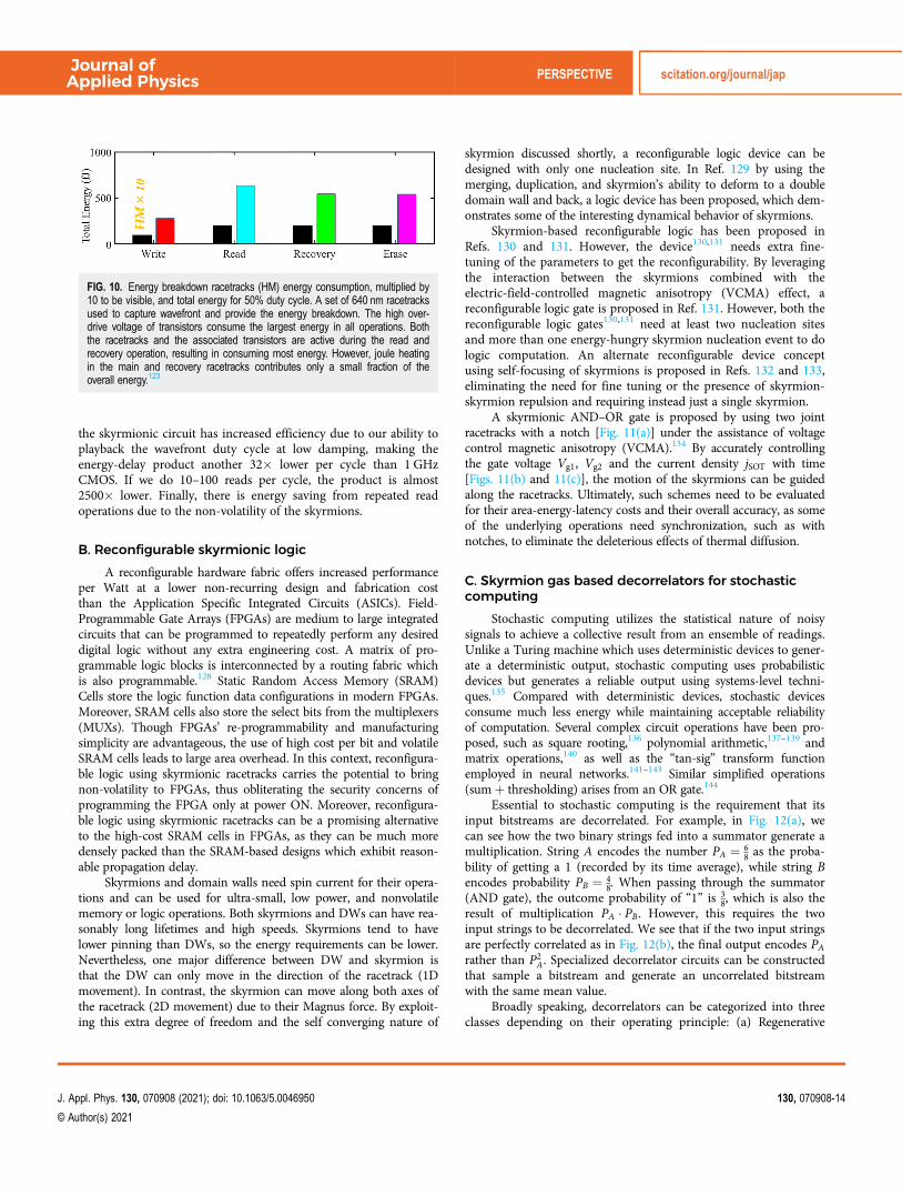
the skyrmionic circuit has increased efficiency due to our ability toplayback the wavefront duty cycle at low damping, making theenergy-delay product another 32� lower per cycle than 1 GHzCMOS. If we do 10–100 reads per cycle, the product is almost2500� lower. Finally, there is energy saving from repeated readoperations due to the non-volatility of the skyrmions.
B. Reconfigurable skyrmionic logic
A reconfigurable hardware fabric offers increased performanceper Watt at a lower non-recurring design and fabrication costthan the Application Specific Integrated Circuits (ASICs). Field-Programmable Gate Arrays (FPGAs) are medium to large integratedcircuits that can be programmed to repeatedly perform any desireddigital logic without any extra engineering cost. A matrix of pro-grammable logic blocks is interconnected by a routing fabric whichis also programmable.128 Static Random Access Memory (SRAM)Cells store the logic function data configurations in modern FPGAs.Moreover, SRAM cells also store the select bits from the multiplexers(MUXs). Though FPGAs’ re-programmability and manufacturingsimplicity are advantageous, the use of high cost per bit and volatileSRAM cells leads to large area overhead. In this context, reconfigura-ble logic using skyrmionic racetracks carries the potential to bringnon-volatility to FPGAs, thus obliterating the security concerns ofprogramming the FPGA only at power ON. Moreover, reconfigura-ble logic using skyrmionic racetracks can be a promising alternativeto the high-cost SRAM cells in FPGAs, as they can be much moredensely packed than the SRAM-based designs which exhibit reason-able propagation delay.
Skyrmions and domain walls need spin current for their opera-tions and can be used for ultra-small, low power, and nonvolatilememory or logic operations. Both skyrmions and DWs can have rea-sonably long lifetimes and high speeds. Skyrmions tend to havelower pinning than DWs, so the energy requirements can be lower.Nevertheless, one major difference between DW and skyrmion isthat the DW can only move in the direction of the racetrack (1Dmovement). In contrast, the skyrmion can move along both axes ofthe racetrack (2D movement) due to their Magnus force. By exploit-ing this extra degree of freedom and the self converging nature of
skyrmion discussed shortly, a reconfigurable logic device can bedesigned with only one nucleation site. In Ref. 129 by using themerging, duplication, and skyrmion’s ability to deform to a doubledomain wall and back, a logic device has been proposed, which dem-onstrates some of the interesting dynamical behavior of skyrmions.
Skyrmion-based reconfigurable logic has been proposed inRefs. 130 and 131. However, the device130,131 needs extra fine-tuning of the parameters to get the reconfigurability. By leveragingthe interaction between the skyrmions combined with theelectric-field-controlled magnetic anisotropy (VCMA) effect, areconfigurable logic gate is proposed in Ref. 131. However, both thereconfigurable logic gates130,131 need at least two nucleation sitesand more than one energy-hungry skyrmion nucleation event to dologic computation. An alternate reconfigurable device conceptusing self-focusing of skyrmions is proposed in Refs. 132 and 133,eliminating the need for fine tuning or the presence of skyrmion-skyrmion repulsion and requiring instead just a single skyrmion.
A skyrmionic AND–OR gate is proposed by using two jointracetracks with a notch [Fig. 11(a)] under the assistance of voltagecontrol magnetic anisotropy (VCMA).134 By accurately controllingthe gate voltage Vg1, Vg2 and the current density jSOT with time[Figs. 11(b) and 11(c)], the motion of the skyrmions can be guidedalong the racetracks. Ultimately, such schemes need to be evaluatedfor their area-energy-latency costs and their overall accuracy, as someof the underlying operations need synchronization, such as withnotches, to eliminate the deleterious effects of thermal diffusion.
C. Skyrmion gas based decorrelators for stochasticcomputing
Stochastic computing utilizes the statistical nature of noisysignals to achieve a collective result from an ensemble of readings.Unlike a Turing machine which uses deterministic devices to gener-ate a deterministic output, stochastic computing uses probabilisticdevices but generates a reliable output using systems-level techni-ques.135 Compared with deterministic devices, stochastic devicesconsume much less energy while maintaining acceptable reliabilityof computation. Several complex circuit operations have been pro-posed, such as square rooting,136 polynomial arithmetic,137–139 andmatrix operations,140 as well as the “tan-sig” transform functionemployed in neural networks.141–143 Similar simplified operations(sumþ thresholding) arises from an OR gate.144
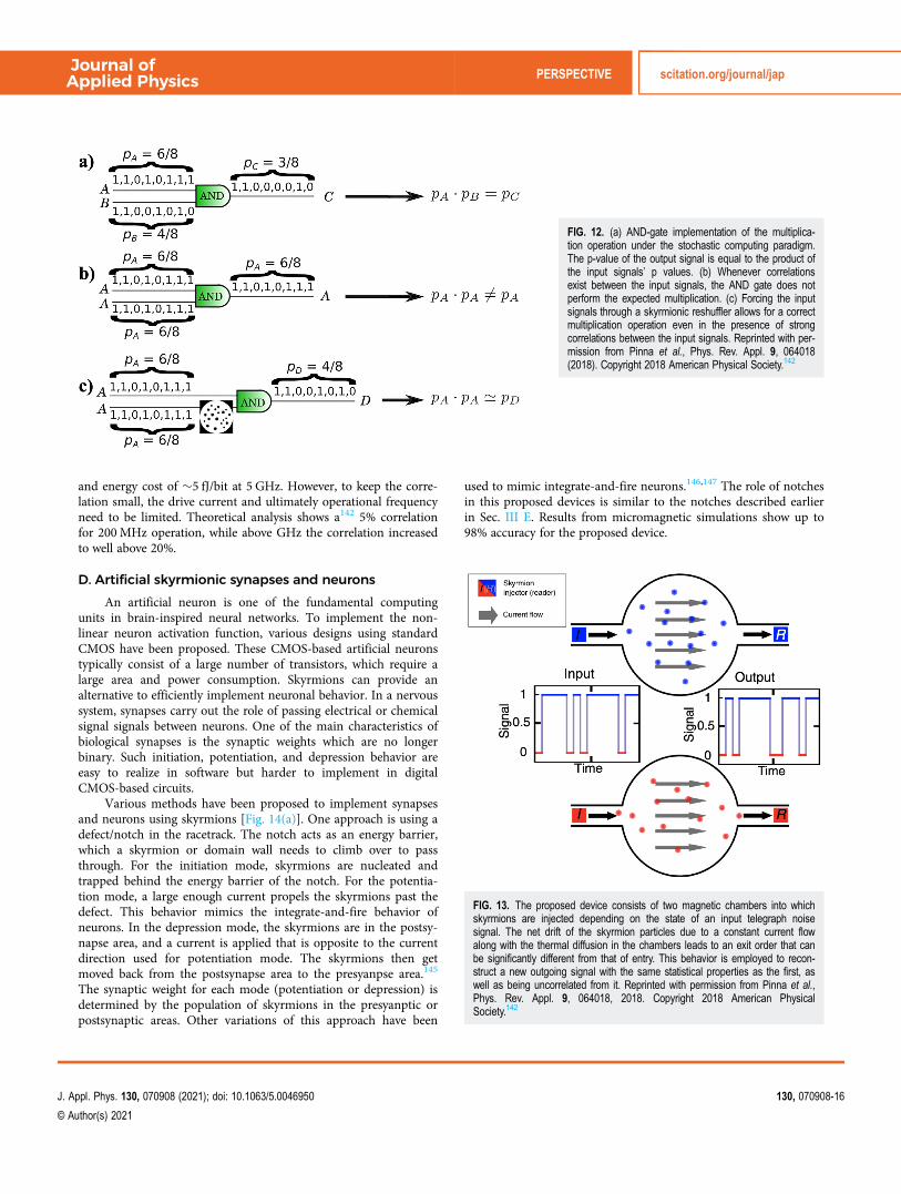
Essential to stochastic computing is the requirement that itsinput bitstreams are decorrelated. For example, in Fig. 12(a), wecan see how the two binary strings fed into a summator generate amultiplication. String A encodes the number PA ¼ 6
8 as the proba-bility of getting a 1 (recorded by its time average), while string Bencodes probability PB ¼ 4
8. When passing through the summator(AND gate), the outcome probability of “1” is 3
8, which is also theresult of multiplication PA � PB. However, this requires the twoinput strings to be decorrelated. We see that if the two input stringsare perfectly correlated as in Fig. 12(b), the final output encodes PArather than P2
A. Specialized decorrelator circuits can be constructedthat sample a bitstream and generate an uncorrelated bitstreamwith the same mean value.
Broadly speaking, decorrelators can be categorized into threeclasses depending on their operating principle: (a) Regenerative
FIG. 10. Energy breakdown racetracks (HM) energy consumption, multiplied by10 to be visible, and total energy for 50% duty cycle. A set of 640 nm racetracksused to capture wavefront and provide the energy breakdown. The high over-drive voltage of transistors consume the largest energy in all operations. Boththe racetracks and the associated transistors are active during the read andrecovery operation, resulting in consuming most energy. However, joule heatingin the main and recovery racetracks contributes only a small fraction of theoverall energy.123
Journal ofApplied Physics PERSPECTIVE scitation.org/journal/jap
J. Appl. Phys. 130, 070908 (2021); doi: 10.1063/5.0046950 130, 070908-14
© Author(s) 2021

decorrelator, which samples the input bitstream to first obtain amean value and then generates a new output stochastic bitstream.This kind of decorrelator generates the best quality decorrelationbut can stall computation due to the delay introduced in sampling.(b) Delay decorrelator that assumes a certain autocorrelation timeof the bitstream source. The input bitstream is copied and“delayed” by a duration more than the autocorrelation time as theoutput bitstream. This ensures that the input and output bitstreamsare uncorrelated due to the nature of the source signal. This is thepreferred approach in pure CMOS-based decorrelators since wemerely need to use a delay path (say, a shift register); however, agood quality decorrelator requires a priori knowledge of the bit-stream source’s autocorrelation time. (c) Reshuffling decorrelator[Fig. 12(c)] that first captures the input bitstream and shuffles their
order to generate the output stream, much like a deck of cardsbeing shuffled after each game to ensure subsequent fair games.The quality of such a decorrelator depends on the length of the bit-stream that can be recorded.
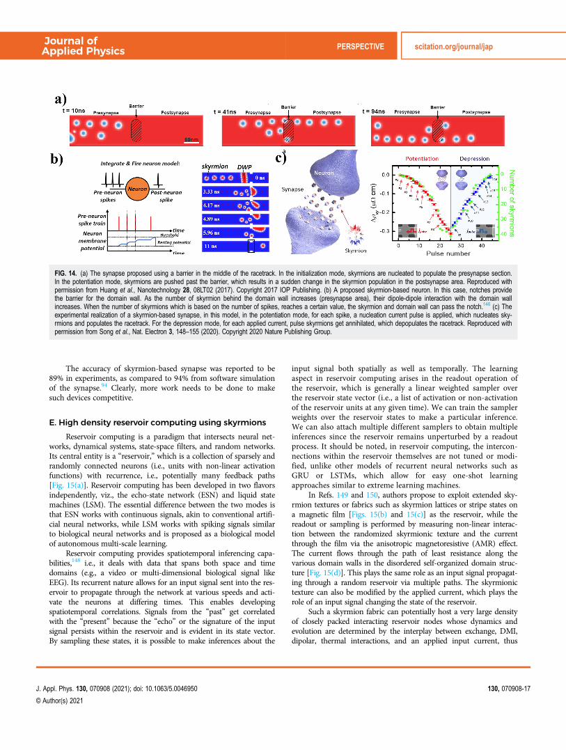
It has been proposed that a magnetic chamber, as shown inFig. 13 can play an efficient role as a skyrmion-based reshufflingdecorrelator. This device is demonstrated by modeling the ensem-ble dynamics in a collective coordinate approach where skyrmion-skyrmion and skyrmion-boundary interactions are accountedfor phenomenologically. The skyrmions’ order gets thermallyreshuffled due to the diffusive 2D dynamical nature of interactingskyrmions at finite temperature. The output stream decorrelatesfrom the input while maintaining the same probability. The pre-dicted decorrelator is compact, at a footprint of μm2, power of μW,
FIG. 11. Skyrmionic AND–OR logic device. (a) Device structure with two input lanes and two output lanes. The two electrode gates (with voltages Vg1 and Vg2) aredesigned to modulate skyrmion motion through the VCMA effect. (b) Profile of driving current density (jSOT) and positive voltages applied to achieve device function.(c)–(e) Three cases of inputs and their corresponding simulated processes and outputs. In the snapshots of the micromagnetic simulations, the color red represents spinup (mz ¼ þ1), blue represents spin down (mz ¼ �1), and white represents spins that are horizontal in the plane (mz ¼ 0). Skyrmion trajectories are indicated in themagnetization snapshots at t ¼ 8 ns. Reprinted with permission from Zhang et al., Phys. Rev. Appl. 13, 054049 (2020). Copyright 2020 American Physical Society.134
Journal ofApplied Physics PERSPECTIVE scitation.org/journal/jap
J. Appl. Phys. 130, 070908 (2021); doi: 10.1063/5.0046950 130, 070908-15
© Author(s) 2021
and energy cost of �5 fJ/bit at 5 GHz. However, to keep the corre-lation small, the drive current and ultimately operational frequencyneed to be limited. Theoretical analysis shows a142 5% correlationfor 200MHz operation, while above GHz the correlation increasedto well above 20%.
D. Artificial skyrmionic synapses and neurons
An artificial neuron is one of the fundamental computingunits in brain-inspired neural networks. To implement the non-linear neuron activation function, various designs using standardCMOS have been proposed. These CMOS-based artificial neuronstypically consist of a large number of transistors, which require alarge area and power consumption. Skyrmions can provide analternative to efficiently implement neuronal behavior. In a nervoussystem, synapses carry out the role of passing electrical or chemicalsignal signals between neurons. One of the main characteristics ofbiological synapses is the synaptic weights which are no longerbinary. Such initiation, potentiation, and depression behavior areeasy to realize in software but harder to implement in digitalCMOS-based circuits.
Various methods have been proposed to implement synapsesand neurons using skyrmions [Fig. 14(a)]. One approach is using adefect/notch in the racetrack. The notch acts as an energy barrier,which a skyrmion or domain wall needs to climb over to passthrough. For the initiation mode, skyrmions are nucleated andtrapped behind the energy barrier of the notch. For the potentia-tion mode, a large enough current propels the skyrmions past thedefect. This behavior mimics the integrate-and-fire behavior ofneurons. In the depression mode, the skyrmions are in the postsy-napse area, and a current is applied that is opposite to the currentdirection used for potentiation mode. The skyrmions then getmoved back from the postsynapse area to the presyanpse area.145
The synaptic weight for each mode (potentiation or depression) isdetermined by the population of skyrmions in the presyanptic orpostsynaptic areas. Other variations of this approach have been
used to mimic integrate-and-fire neurons.146,147 The role of notchesin this proposed devices is similar to the notches described earlierin Sec. III E. Results from micromagnetic simulations show up to98% accuracy for the proposed device.
FIG. 12. (a) AND-gate implementation of the multiplica-tion operation under the stochastic computing paradigm.The p-value of the output signal is equal to the product ofthe input signals’ p values. (b) Whenever correlationsexist between the input signals, the AND gate does notperform the expected multiplication. (c) Forcing the inputsignals through a skyrmionic reshuffler allows for a correctmultiplication operation even in the presence of strongcorrelations between the input signals. Reprinted with per-mission from Pinna et al., Phys. Rev. Appl. 9, 064018(2018). Copyright 2018 American Physical Society.142
FIG. 13. The proposed device consists of two magnetic chambers into whichskyrmions are injected depending on the state of an input telegraph noisesignal. The net drift of the skyrmion particles due to a constant current flowalong with the thermal diffusion in the chambers leads to an exit order that canbe significantly different from that of entry. This behavior is employed to recon-struct a new outgoing signal with the same statistical properties as the first, aswell as being uncorrelated from it. Reprinted with permission from Pinna et al.,Phys. Rev. Appl. 9, 064018, 2018. Copyright 2018 American PhysicalSociety.142
Journal ofApplied Physics PERSPECTIVE scitation.org/journal/jap
J. Appl. Phys. 130, 070908 (2021); doi: 10.1063/5.0046950 130, 070908-16
© Author(s) 2021
The accuracy of skyrmion-based synapse was reported to be89% in experiments, as compared to 94% from software simulationof the synapse.94 Clearly, more work needs to be done to makesuch devices competitive.
E. High density reservoir computing using skyrmions
Reservoir computing is a paradigm that intersects neural net-works, dynamical systems, state-space filters, and random networks.Its central entity is a “reservoir,” which is a collection of sparsely andrandomly connected neurons (i.e., units with non-linear activationfunctions) with recurrence, i.e., potentially many feedback paths[Fig. 15(a)]. Reservoir computing has been developed in two flavorsindependently, viz., the echo-state network (ESN) and liquid statemachines (LSM). The essential difference between the two modes isthat ESN works with continuous signals, akin to conventional artifi-cial neural networks, while LSM works with spiking signals similarto biological neural networks and is proposed as a biological modelof autonomous multi-scale learning.
Reservoir computing provides spatiotemporal inferencing capa-bilities,148 i.e., it deals with data that spans both space and timedomains (e.g., a video or multi-dimensional biological signal likeEEG). Its recurrent nature allows for an input signal sent into the res-ervoir to propagate through the network at various speeds and acti-vate the neurons at differing times. This enables developingspatiotemporal correlations. Signals from the “past” get correlatedwith the “present” because the “echo” or the signature of the inputsignal persists within the reservoir and is evident in its state vector.By sampling these states, it is possible to make inferences about the
input signal both spatially as well as temporally. The learningaspect in reservoir computing arises in the readout operation ofthe reservoir, which is generally a linear weighted sampler overthe reservoir state vector (i.e., a list of activation or non-activationof the reservoir units at any given time). We can train the samplerweights over the reservoir states to make a particular inference.We can also attach multiple different samplers to obtain multipleinferences since the reservoir remains unperturbed by a readoutprocess. It should be noted, in reservoir computing, the intercon-nections within the reservoir themselves are not tuned or modi-fied, unlike other models of recurrent neural networks such asGRU or LSTMs, which allow for easy one-shot learningapproaches similar to extreme learning machines.
In Refs. 149 and 150, authors propose to exploit extended sky-rmion textures or fabrics such as skyrmion lattices or stripe states ona magnetic film [Figs. 15(b) and 15(c)] as the reservoir, while thereadout or sampling is performed by measuring non-linear interac-tion between the randomized skyrmionic texture and the currentthrough the film via the anisotropic magnetoresistive (AMR) effect.The current flows through the path of least resistance along thevarious domain walls in the disordered self-organized domain struc-ture [Fig. 15(d)]. This plays the same role as an input signal propagat-ing through a random reservoir via multiple paths. The skyrmionictexture can also be modified by the applied current, which plays therole of an input signal changing the state of the reservoir.
Such a skyrmion fabric can potentially host a very large densityof closely packed interacting reservoir nodes whose dynamics andevolution are determined by the interplay between exchange, DMI,dipolar, thermal interactions, and an applied input current, thus
FIG. 14. (a) The synapse proposed using a barrier in the middle of the racetrack. In the initialization mode, skyrmions are nucleated to populate the presynapse section.In the potentiation mode, skyrmions are pushed past the barrier, which results in a sudden change in the skyrmion population in the postsynapse area. Reproduced withpermission from Huang et al., Nanotechnology 28, 08LT02 (2017). Copyright 2017 IOP Publishing. (b) A proposed skyrmion-based neuron. In this case, notches providethe barrier for the domain wall. As the number of skyrmion behind the domain wall increases (presynapse area), their dipole-dipole interaction with the domain wallincreases. When the number of skyrmions which is based on the number of spikes, reaches a certain value, the skyrmion and domain wall can pass the notch.146 (c) Theexperimental realization of a skyrmion-based synapse, in this model, in the potentiation mode, for each spike, a nucleation current pulse is applied, which nucleates sky-rmions and populates the racetrack. For the depression mode, for each applied current, pulse skyrmions get annihilated, which depopulates the racetrack. Reproduced withpermission from Song et al., Nat. Electron 3, 148–155 (2020). Copyright 2020 Nature Publishing Group.
Journal ofApplied Physics PERSPECTIVE scitation.org/journal/jap
J. Appl. Phys. 130, 070908 (2021); doi: 10.1063/5.0046950 130, 070908-17
© Author(s) 2021
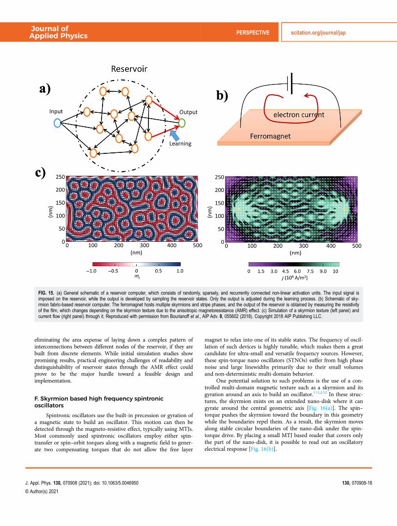
eliminating the area expense of laying down a complex pattern ofinterconnections between different nodes of the reservoir, if they arebuilt from discrete elements. While initial simulation studies showpromising results, practical engineering challenges of readability anddistinguishability of reservoir states through the AMR effect couldprove to be the major hurdle toward a feasible design andimplementation.
F. Skyrmion based high frequency spintronicoscillators
Spintronic oscillators use the built-in precession or gyration ofa magnetic state to build an oscillator. This motion can then bedetected through the magneto-resistive effect, typically using MTJs.Most commonly used spintronic oscillators employ either spin-transfer or spin–orbit torques along with a magnetic field to gener-ate two compensating torques that do not allow the free layer
magnet to relax into one of its stable states. The frequency of oscil-lation of such devices is highly tunable, which makes them a greatcandidate for ultra-small and versatile frequency sources. However,these spin-torque nano oscillators (STNOs) suffer from high phasenoise and large linewidths primarily due to their small volumesand non-deterministic multi-domain behavior.
One potential solution to such problems is the use of a con-trolled multi-domain magnetic texture such as a skyrmion and itsgyration around an axis to build an oscillator.151,152 In these struc-tures, the skyrmion exists on an extended nano-disk where it cangyrate around the central geometric axis [Fig. 16(a)]. The spin–torque pushes the skyrmion toward the boundary in this geometrywhile the boundaries repel them. As a result, the skyrmion movesalong stable circular boundaries of the nano-disk under the spin-torque drive. By placing a small MTJ based reader that covers onlythe part of the nano-disk, it is possible to read out an oscillatoryelectrical response [Fig. 16(b)].
FIG. 15. (a) General schematic of a reservoir computer, which consists of randomly, sparsely, and recurrently connected non-linear activation units. The input signal isimposed on the reservoir, while the output is developed by sampling the reservoir states. Only the output is adjusted during the learning process. (b) Schematic of sky-rmion fabric-based reservoir computer. The ferromagnet hosts multiple skyrmions and stripe phases, and the output of the reservoir is obtained by measuring the resistivityof the film, which changes depending on the skyrmion texture due to the anisotropic magnetoresistance (AMR) effect. (c) Simulation of a skyrmion texture (left panel) andcurrent flow (right panel) through it. Reproduced with permission from Bourianoff et al., AIP Adv. 8, 055602 (2018). Copyright 2018 AIP Publishing LLC.
Journal ofApplied Physics PERSPECTIVE scitation.org/journal/jap
J. Appl. Phys. 130, 070908 (2021); doi: 10.1063/5.0046950 130, 070908-18
© Author(s) 2021

The frequency of oscillation of the skyrmionic nano-oscillatordepends on not only the magnitude of the driving spin-torque[Fig. 16(c)] but also the skyrmion size, nano-disk radius [Fig. 16(d)],and the drive current, providing a rich phase space for oscillatordesign. It was also reported in Ref. 151 that the linewidth was lessthan a 1MHz with a central frequency of nearly 800MHz, whereasGarcia-Sanchez et al.152 reported a somewhat lower center frequencyof a few 100s of MHz. Analysis from both papers indicated that sky-rmion motion could be fairly robust against moderate disorders suchas grain structure of the magnetic nano-disk and other imperfectionssuch as bubbles, dots, and notches. Using additional skyrmions onthe nano-disk can increase the frequency to more than 1 GHz byreading these multiple skyrmions in a single gyration.151
V. TECHNOLOGY CHALLENGES
On the road toward reliable low cost and energy-efficient sky-rmionics, there are many challenges. Depending on the targetapplication, they can be of varying importance. For conservativememory or logic based on shuttling skyrmions around, such as ouraforementioned temporal memory and other Boolean computingideas,153 any nucleation of skyrmions needs to be deterministic
both in position and in number. On the other hand, stochasticapplications such as skyrmion reshufflers are not sensitive to theposition and quantity of nucleated skyrmions, although they couldbe sensitive to other aspects such as the rate of nucleation.Regardless of the precise application, we can identify somecommon challenges relating to overhead cost and integrability,readability, stability, gateability, and nucleation/annihilation.
To start with, the energy advantage of a skyrmionic circuit(for that matter, any computing paradigm) needs to be evaluatedin totality, including the control and read circuitry. As pointed outnear the introduction, the bulk of the energy bottleneck with mag-netic devices lies in the overhead. We saw that with our temporalmemory analysis (Sec. IV B), where the energy consumed in theracetrack was �10 fJ, while that in the CMOS transistors used toturn the currents on and off consumed �1 pJ. While the domi-nance of the overhead is perhaps unavoidable with electronic inter-faces, the opportunity could very well lie in our ability to map acompact skyrmionic architecture with a particular algorithm itsunderlying physics naturally accelerates, such as its tunable lineardynamics for analog computing. Such a mapping could signifi-cantly reduce the electronic overhead (e.g., eight transistors forwavefront memory vs hundreds for a CMOS-only layout).
FIG. 16. (a) Schematic of a skyrmionic nano-oscillator (SkNO). Skyrmions are placed in a wide nano-disk, whereupon applying a spin torque through the injection of aspin current drives the skyrmion in a circular orbit through the disk. The readout is done through a small MTJ structure placed on the nano-disk, which samples the sky-rmion every period of the gyration orbit. (b) Simulation showing the trajectory of the skyrmion on the nano-disk and the motion through the x-axis (from Ref. 151).(c) Dependence on the central oscillation frequency with current density for various applied magnetic field strength [Garcia-Sanchez et al., New J. Phys. 18, 075011(2016). Copyright 2016 Author(s), licensed under a Creative Commons Attribution (CC BY) license]. (d) Dependence of the central oscillation frequency with the nano-diskradius, given a fixed current density and (left panel) injection point contact radius and (right panel) skyrmion radius (b) and (d) from Zhang et al., New J. Phys. 17, 023061(2015). Copyright 2016 Author(s), licensed under a Creative Commons Attribution (CC BY) license.151
Journal ofApplied Physics PERSPECTIVE scitation.org/journal/jap
J. Appl. Phys. 130, 070908 (2021); doi: 10.1063/5.0046950 130, 070908-19
© Author(s) 2021

Driveability will also require an optimized material thicknessthat allows long lifetimes and thermal stability, while also providingadequate interfacial DMI and SOT coefficients. This also means weneed to evaluate the compatibility of the various components—forinstance, impedance matching between the transistors and theheavy metal underlayers, or the ability for these transistors toprovide adequate drive current or voltage (e.g., some of the logicapplications need �2 V VCMA gating, more than the nominalvoltage of a 180 nm transistor).
Adequate drivability requires an electronic read unit to detectskyrmions for each logic operation. This in itself is challenginggiven the small footprint of a skyrmion relative to an MTJ, exacer-bated in ferrimagnets. Moreover, after reading the data, an ampli-fier will be needed to have a reliable output resulting in extraenergy and area overhead.
As with many emerging technologies, appropriate gate designfor suitable electrostatic or anisotropy control, as well as materialintegration (channel, oxide, and heavy metal), will need to be per-fected. Some of the logic setups rely on precise gate synchronizationof skyrmion arrival times, which can be challenging in presence ofthermal fluctuations and diffusion. A non-uniform defect densitycan alter the arrival sequence in a temporal memory device orchange the output in a two-lane AND–OR device. In Fig. 11, wehave assumed two-input gates, so the geometry needs to be alteredfor a larger number of inputs to avoid cascading, that can becomeprohibitively costly. On the other hand, altering device geometrymay result in reliability issues. In such circumstances, it may beworthwhile to pay the cost penalty rather than playing with thedevice geometry that can compromise reliability. Energy, delay andreliability form a triad whose elements can be traded-off againsteach other depending on specific application thresholds.
Finally, reliable nucleation of skyrmions will be an issue for allnon-stochastic devices, especially ones that rely on re-nucleatingskyrmions rather than reshuffling them around. Reliable nucleationmaybe less relevant for stochastic computing applications depend-ing on their error thresholds. For reshuffler-based applications(Fig. 13), a synchronization between the speeds of injection, nucle-ation, and expulsion needs to be ensured to avoid bottlenecks thatcan delay the overall performance by a handsome margin andhamper its reliability. There are other considerations—for instance,higher current densities might enforce higher degrees of correlationamong bitstreams, which stochastic computing seeks to avoid. Letus now discuss how we may address some of these challenges.
A. Readability
To use skyrmions or DWs in a digital circuit, we need to beable to electrically detect these magnetic excitations. The mostpractical method for detecting isolated skyrmions is using MTJs.When a skyrmion or DW reaches an MTJ, the correspondingtunnel magnetoresistance (TMR) generates an output voltage swingwhich needs to be amplified to get a 0/1 in the output node of thecircuit. In order to have a large enough voltage swing without anyerroneous electrical detection, the TMR needs to be quite large,50% in our proposed race logic and reconfigurable hardware appli-cations. Owing to the small size and chiral spin texture of sky-rmions, the effective TMR is set by an overall filling factor and can
be significantly smaller than the TMR for a magnetic pillar. For askyrmion of the same size as the MTJ, this fill factor can be assmall as 30% [TMReffective ¼ (fill factor)� TMR]. The TMR can besmaller for ferrimagnets or antiferromagnets as the two sub-latticespins can oppose each other. TMR ratios of above 100 have beentheoretically predicted for antiferromagnets,154,155 but so far noexperiment has demonstrated large TMR ratios for AFMs. Theanisotropic magnetoresistance (AMR), varying with applied currentdensity jc as � (m � jc)2, has also been investigated for canted mag-netic structures including skyrmions,155 and predicted to rise above100 percent magnetoresistance (MR) ratio,156 though a room tem-perature experimental demonstration is as yet unavailable.Multilayer spin valve structures with synthetic antiferromagnet(SAF) or an intermediate ferromagnetic layer157,158 are other possi-bilities. By tuning the bias voltage and reference resistance of theread unit, erroneous data detection seems preventable at a some-what low effective TMR (�50%), but the circuit might not berobust enough against variations. In a synchronously clockedsystem, perhaps where notches quantize the racetrack in the mag-netic substrate, a more sensitive detection mechanism like aPre-Charged Sense Amplifier (PCSA)159 could be adopted if indeedvery low effective TMR becomes a persistent problem.
An alternate way to detect a skyrmion is to look for chiral sig-natures in a Hall measurement. In magnetic materials there are threecomponents to the transverse resistivity, ρxy ¼ ρOHE
xy þ ρAHExy þ ρTHE
xy .The first one, ρOHE
xy , is the ordinary Hall effect (OHE). The secondone, ρAHExy proportional to the out-of-plane magnetization mz , is theanomalous Hall effect (AHE). The last one, the topological Halleffect (THE), is induced by the skyrmion’s chiral spin texture. THE,is reported to be dominant in B20 skyrmion lattices, but for isolatedskyrmions, the AHE becomes the dominant contribution to thetransverse Hall resistivity. The magnitude of ρxy is small for a singleskyrmion, but for a larger number of skyrmions, it can have thenecessary voltage swing for it to be useful in an electrical circuit. TheΔρxy reported for a single skyrmion can be as small as3:5+ 0:5 nΩ-cm for sub-100 nm skyrmions in racetrack width of1 μm.160 For a current density of 1 TA m�2 and width of 1 μm, thevoltage swing would be 3.5 mV.
B. Deterministic nucleation/annihilation
As we discussed in Sec. III C, there are multiple mechanismsavailable to nucleate and annihilate skyrmions, ranging from exter-nal magnetic fields to current pulses to defect sites with locallyreduced magnetic anisotropy.51 The challenge, however, is to makethis deterministic, since the methods discussed can lead to inadver-tent nucleation of multiple skyrmions.56,160 Moreover, the positionof the nucleated skyrmions needs to be deterministic,92 meaningthat the pinning sites for skyrmion nucleation need to be con-trolled. For applications where single skyrmions are used to encodedata,123,130,133 the unpredictability of location or number of sky-rmions would make the device unworkable. One way around is todesign the device so that it can be conservative in the number ofskyrmions,123,153 meaning there is no need for annihilation in thefirst place. The benefit of conservative devices is that the skyrmionscan be pre-fabricated in a controlled environment. It is also impor-tant to avoid added nucleation. Current pulses of magnitude above
Journal ofApplied Physics PERSPECTIVE scitation.org/journal/jap
J. Appl. Phys. 130, 070908 (2021); doi: 10.1063/5.0046950 130, 070908-20
© Author(s) 2021

jc � 1012 A=m2 are typically used to nucleate skyrmions, in fact,even a bit lower sometimes due to thermal effects.92,95 This meansthe operational current, j of the device, needs to be well below thenucleation/annihilation limit. On the other hand, the current has tobe large enough to unpin the skyrmion. For the applications wherethe density of skyrmions is important, for example, neuromorphicapplications,144 the deterministic nucleation/annihilation of indi-vidual skyrmions would influence the ratio at which they arecreated or deleted, and thus the overall probability of ones andzeros. This would also be sensitive to the magnitude of currentdensity and defects.
In addition to deterministic challenges, skyrmion nucleationcan be energetically costly,161 as the current pulse In for nucleationneeds to be larger than the driving current Id . The power consump-tion would be (In=Id)
2 times higher, which combined with nucle-ation time would make each creation/annihilation processenergy-hungry, arguing for a conservative design that shuttlesrather than creates/destroys skyrmions repeatedly. Our pulseduration studies discussed in Sec. III C place the nucleation time at�1–10 ns, comparable to drive time. Reference 95 uses a currentpulse of 1012 Am�2 over 6 ns for nucleation, while the drive timewe estimated for race logic across a 640 nm racetrack was under10 ns. Reusing pre-fabricated skyrmions would make the recoveryoperation in race logic 1-2 orders of magnitude moreenergy-efficient than nucleating skyrmions each cycle.
C. Positional stability
Large skyrmions generally have larger lifetimes and more dif-fusion, while small ones get easily pinned by defects and gothrough a thermally activated creep regime in transport. Theamount of diffusion needs to be tightly restricted to service theneeds of a given technology (Table III). In order to ensure the reli-ability of the magnetic memory, pinning sites need to be engi-neered lithographically. The pinning energy barrier needs to belarge enough to stabilize skyrmion location and, depending on theapplication, similar to the lifetime energy barrier, around 30 to 50kBT . Much like the lifetime, there is a trade-off between havingadequate skyrmion stability (higher barriers) vs modest drive cur-rents that can unpin and move them efficiently without blowing upthe energy budget, crashing them into the sidewalls, or otherwiseannihilating them in the process. In addition, if the driving currentis too large, it can nucleate unwanted skyrmions. In the case ofdomain walls, similar positional stability is needed, but unavoidablelithographic edge roughness can cause significant DW pinning inthe racetrack. Controlling the amount of pinning for skyrmionsmight be easier to achieve as they can avoid edges, implying a dis-tinct advantage in terms of material engineering.
D. Integration challenge
The magnetic racetracks need to be integrated with siliconCMOS transistors that constitute the control circuitry for memory/logic applications. The difficulty in designing a high-speed sky-rmionic device is the large current needed to move the skyrmion athigh speed. Due to the impedance mismatch between the heavymetal underlayer and CMOS control circuitry, only a tiny fractionof current is fed to the racetrack, limiting our scope for supply
voltage reduction. Using larger transistors will reduce their resist-ance, allowing a high drive current. Since the control circuitryconsumes the bulk portion of the overall energy (Fig. 10),123 thereduction of transistor resistance will reduce the overall energy con-sumption by balancing the impedance between the racetrack andthe circuitry, allowing higher frequency operation enabled byhigher skyrmion speeds, albeit with an associated area overhead forthe larger transistors.
For conventional racetrack memories, the energy consumptionratio between the CMOS and the racetrack underlayer will dependon the number of skyrmions in the racetrack and the number ofread stacks placed on the racetrack. As the applied current to theracetrack underlayer will move all the skyrmions present in theracetrack, the driving energy consumption ratio of CMOS/racetrackwill be lower for a higher number of skyrmions in a racetrack.Thus, longer racetracks and a higher number of small-sized sky-rmions will lower energy consumption. However, smaller sky-rmions are harder to detect, and longer wires are more susceptibleto noise, creating erroneous output. Thus, to achieve energy effi-ciency without affecting reliability (a trade-off we emphasized nearthe start of this article), choosing the optimal racetrack length andskyrmion size will be vital. However, it is worth mentioning thatthe skyrmion nucleation energy will be a deciding factor of theoverall energy consumption for the conventional multi-skyrmionracetrack memory.
There is also an issue of current sharing between metallicmagnets with the heavy metal underlayer, which can be mitigatedby using insulating magnetic oxides such as spinels and ferrites.The physics gets considerably more involved in antiferromagneticspin dynamics which has added inertial terms and will need to beexplicitly re-evaluated for skyrmion transport.
E. Speed stability
As was mentioned in Sec. I C, skyrmions need to be fast whilerequiring a small drive current to guarantee energy efficiency. Besidesenergy efficiency constraints, we get two limits on the current range.As seen in Fig. 5, too large a drive current can distort and dissolvethe skyrmions and create overall nonlinearity, which sets the upperlimit. On the other hand, the minimum current must be sufficient tounpin skyrmions away from engineered pinning sites and thus set bythe required positional lifetime of the skyrmions.
VI. SUMMARY/OUTLOOK
Recent experiments have unearthed a wealth of solitonic exci-tations in thin magnets, from skyrmions to skyrmioniums andchiral bobbers.162 What makes these entities interesting is that theycan be scaled down to fairly small sizes through material engineer-ing, utilizing their topological barriers that work effectively againstthermal fluctuations, especially if the sizes are not too small.Topology also covers their dynamical properties as these excitationscan work around defects by distorting their shapes at low currentdensities. The size scaling offers distinct advantages relating tohigh-density information encoding that can be challenging toaccomplish with conventional magnets. Their quasi-linear current-driven motion and tunable properties would allow certain applica-tions such as temporal racetrack memory for low-density
Journal ofApplied Physics PERSPECTIVE scitation.org/journal/jap
J. Appl. Phys. 130, 070908 (2021); doi: 10.1063/5.0046950 130, 070908-21
© Author(s) 2021
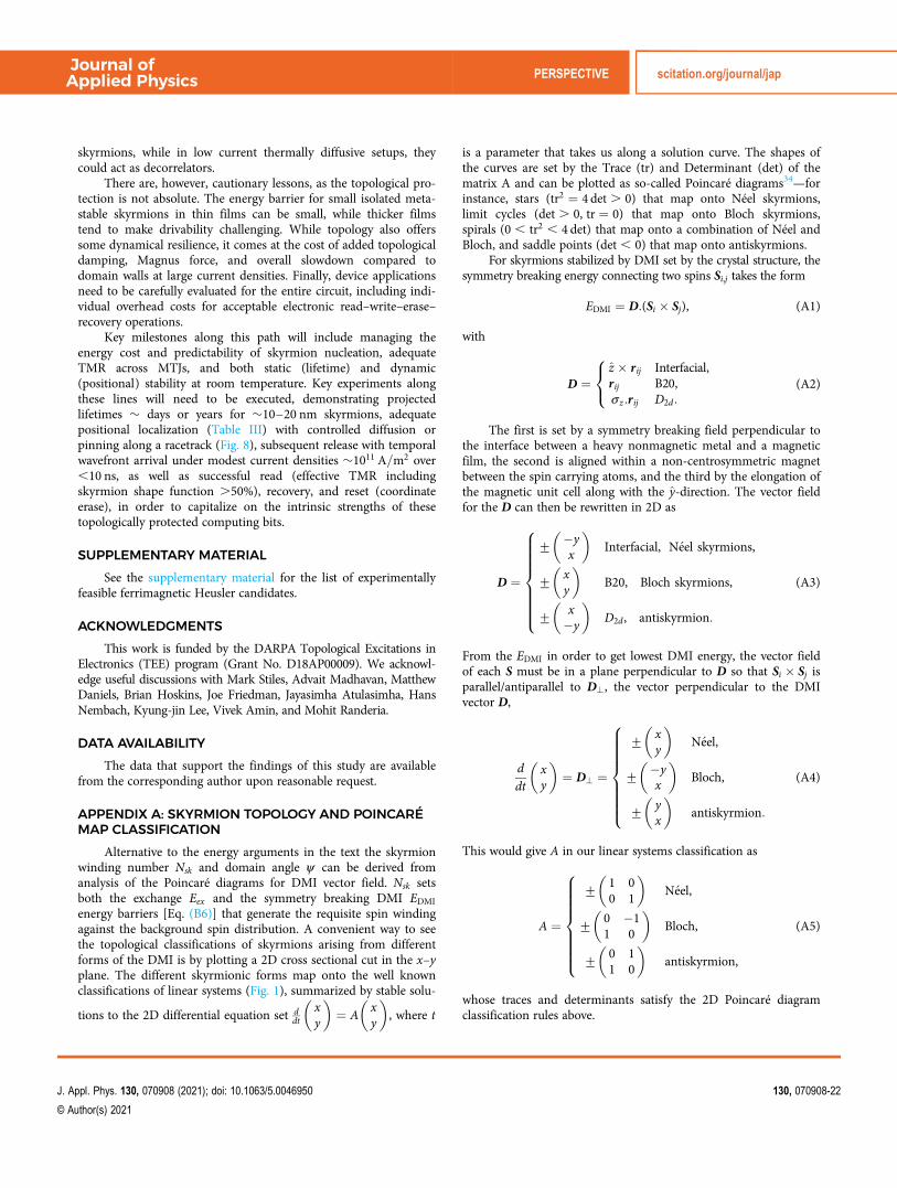
skyrmions, while in low current thermally diffusive setups, theycould act as decorrelators.
There are, however, cautionary lessons, as the topological pro-tection is not absolute. The energy barrier for small isolated meta-stable skyrmions in thin films can be small, while thicker filmstend to make drivability challenging. While topology also offerssome dynamical resilience, it comes at the cost of added topologicaldamping, Magnus force, and overall slowdown compared todomain walls at large current densities. Finally, device applicationsneed to be carefully evaluated for the entire circuit, including indi-vidual overhead costs for acceptable electronic read–write–erase–recovery operations.
Key milestones along this path will include managing theenergy cost and predictability of skyrmion nucleation, adequateTMR across MTJs, and both static (lifetime) and dynamic(positional) stability at room temperature. Key experiments alongthese lines will need to be executed, demonstrating projectedlifetimes � days or years for �10–20 nm skyrmions, adequatepositional localization (Table III) with controlled diffusion orpinning along a racetrack (Fig. 8), subsequent release with temporalwavefront arrival under modest current densities �1011 A=m2 over,10 ns, as well as successful read (effective TMR includingskyrmion shape function .50%), recovery, and reset (coordinateerase), in order to capitalize on the intrinsic strengths of thesetopologically protected computing bits.
SUPPLEMENTARY MATERIAL
See the supplementary material for the list of experimentallyfeasible ferrimagnetic Heusler candidates.
ACKNOWLEDGMENTS
This work is funded by the DARPA Topological Excitations inElectronics (TEE) program (Grant No. D18AP00009). We acknowl-edge useful discussions with Mark Stiles, Advait Madhavan, MatthewDaniels, Brian Hoskins, Joe Friedman, Jayasimha Atulasimha, HansNembach, Kyung-jin Lee, Vivek Amin, and Mohit Randeria.
DATA AVAILABILITY
The data that support the findings of this study are availablefrom the corresponding author upon reasonable request.
APPENDIX A: SKYRMION TOPOLOGY AND POINCARÉMAP CLASSIFICATION
Alternative to the energy arguments in the text the skyrmionwinding number Nsk and domain angle ψ can be derived fromanalysis of the Poincaré diagrams for DMI vector field. Nsk setsboth the exchange Eex and the symmetry breaking DMI EDMI
energy barriers [Eq. (B6)] that generate the requisite spin windingagainst the background spin distribution. A convenient way to seethe topological classifications of skyrmions arising from differentforms of the DMI is by plotting a 2D cross sectional cut in the x–yplane. The different skyrmionic forms map onto the well knownclassifications of linear systems (Fig. 1), summarized by stable solu-
tions to the 2D differential equation set ddt
xy
� �¼ A
xy
� �, where t
is a parameter that takes us along a solution curve. The shapes ofthe curves are set by the Trace (tr) and Determinant (det) of thematrix A and can be plotted as so-called Poincaré diagrams34—forinstance, stars (tr2 ¼ 4 det . 0) that map onto Néel skyrmions,limit cycles (det . 0, tr ¼ 0) that map onto Bloch skyrmions,spirals (0 , tr2 , 4 det) that map onto a combination of Néel andBloch, and saddle points (det , 0) that map onto antiskyrmions.
For skyrmions stabilized by DMI set by the crystal structure, thesymmetry breaking energy connecting two spins Si,j takes the form
EDMI ¼ D:(Si � Sj), (A1)
with
D ¼z � rij Interfacial,rij B20,σz:rij D2d:
8<: (A2)
The first is set by a symmetry breaking field perpendicular tothe interface between a heavy nonmagnetic metal and a magneticfilm, the second is aligned within a non-centrosymmetric magnetbetween the spin carrying atoms, and the third by the elongation ofthe magnetic unit cell along with the y-direction. The vector fieldfor the D can then be rewritten in 2D as
D ¼
+�yx
� �Interfacial, N�eel skyrmions,
+xy
� �B20, Bloch skyrmions,
+x�y
� �D2d , antiskyrmion:
8>>>>>>><>>>>>>>:
(A3)
From the EDMI in order to get lowest DMI energy, the vector fieldof each S must be in a plane perpendicular to D so that Si � Sj isparallel/antiparallel to D?, the vector perpendicular to the DMIvector D,
ddt
xy
� �¼ D? ¼
+xy
� �N�eel,
+�yx
� �Bloch,
+yx
� �antiskyrmion:
8>>>>>>><>>>>>>>:
(A4)
This would give A in our linear systems classification as
A ¼
+1 00 1
� �N�eel,
+0 �11 0
� �Bloch,
+0 11 0
� �antiskyrmion,
8>>>>>>><>>>>>>>:
(A5)
whose traces and determinants satisfy the 2D Poincaré diagramclassification rules above.
Journal ofApplied Physics PERSPECTIVE scitation.org/journal/jap
J. Appl. Phys. 130, 070908 (2021); doi: 10.1063/5.0046950 130, 070908-22
© Author(s) 2021

We can quantify the winding of spins around the skyrmionwith the winding number Nsk introduced earlier (Sec. I C). An elec-tron moving around a closed loop on the Fermi surface picks up ageometrical Berry phase related to the solid angle subtended at thecenter of the Fermi sphere, similar to the precession of a Foucaultpendulum. This phase is given by the flux of the magnetic field inthe k-space, fn ¼
Þ~Bk � d~Sk, ~Bk ¼ ~∇k �~Ak, ~Ak ¼ iu*k~∇kuk, where
uk is the Bloch part of the electron wavefunction. For magnets, thecorresponding phase space k ! m, where m is the normalizedmagnetic moment. We use a standard 2� 1 spinor representation
um ¼ exp [� iΨ=2] cos θ=2exp [iΨ=2] sin θ=2
� �. The corresponding magnetic field
then maps onto a magnetic monopole while the Chern number isset by the quantum of the Berry flux, Cn ¼ fn=2π; 2D Cn simpli-fies to Nsk.
APPENDIX B: SKYRMION ENERGY TERMS
In a 1D continuum representation, the width of a domain wallarises from a competition between exchange stiffness Aex and uni-axial anisotropy Ku. Taking into account only the first two energyterms, we get the energy per unit area
E0 ¼ tF
ð1�1
dx[Aex(dθ=dx)2 � Ku cos
2 θ]: (B1)
Minimizing this energy, i.e., invoking Euler–Lagrange’s equations,leads to the differential equation
d2θdx2
¼ sin θ cos θ
Δ20
, (B2)
where Δ0 ¼ffiffiffiffiffiffiffiffiffiffiffiffiffiffiAex=Ku
pis the domain wall width (exchange
wants to spread the spins around, uniaxial anisotropy wants toalign them). Solving this equation with boundary conditionsdθ=dxjx¼1 ¼ 0 gives us the equation for a 1D domain wall as
θ(x) ¼ 2 tan�1 e(x � x0)=Δ0h i
spread over a thickness Δ0 around the
position x0. We can then approximate the various integrals per unitarea as
E0ex ¼ tF
ð1�1
dxAex(dθ=dx)2 ¼ 2Aex=Δ0,
E0ani ¼ tFKu
ð1�1
dx sin2 θ ¼ 2KuΔ0,(B3)
where we used the differential equation above to replace onedθ=dx ¼ sin θ=Δ0 term in each of the first two integrals. We can alsocalculate the 1D equivalent of a chiral DMI energy as
E0DMI ¼ �tF sinψ0D
ð1�1
dxdθ=dx ¼ �πtFD sinψ0, (B4)
where ψ0 is the domain wall angle, ψ0 ¼ 0 is a Bloch domain wall,and ψ0 ¼ π=2 is a Néel domain wall. The full 3D form of Eq. (B1)with DMI corrections should be taken into account to describe 2Dskyrmions. Writing m in spherical cooridnates, m ¼ sin θ cosψ ,ð
sin θ sinψ , cos θÞ and using Euler–Lagrange’s equation, the solu-tions for θ(r) can be approximated as two opposing domain wallsat antipodal locations,
θ(r) ¼ 2 tan�1 sinh (Rsk=Δ)sinh (r=Δ)
�, (B5)
where Rsk is the radius of the core. Substituting this form, we canevaluate all the energy integrals36–38
Eex ¼ (2πAextF)2Rsk
Δþ 2ΔRsk
N2sk
� �fex(ρ),
EDMI ¼ � 2πRsktFð ÞπDfDMI(ρ),
Eani ¼ 4πKutFð ÞRskΔfani(ρ),
EZeeman ¼ πR2sktF
� � 2μ0MSHzð ÞfZeeman(ρ),
Edemag ¼ � 2πμ0M2s tF
� RskΔ
�(fs(ρ, tFM=Δ)� cosψ2fv(ρ, tFM=Δ)),
with D ; Dint cosψ � Dbulk sinψð Þ,
(B6)
where ψ is once again the domain tilt angle. fs(ρ, tFM=Δ) andfs(ρ, tFM=Δ) are surface and volume demagnetization form factors,respectively. For ultrathin film limit, tFM � Δ, Rskm, fs ≃ fani and fvcan be ignored.39 The form factors for small size, obtained byfitting numerical simulations, are given by
fex(ρ) � 1þ 1:93ρ ρ� 0:65ð Þ
ρ2 þ 1e�1:48(ρ�0:65)
�,
fani(ρ) � 1� 16ρ
e�ρ=ffiffi2
p �,
fDMI(ρ) � Nsk þ 12πρ
e�ρ
�,
fZeeman(ρ) � 1þ π2
12ρ2� 0:42
ρ2e�ρ2
�:
(B7)
We have deliberately separated out the large radius expres-sions, which are easy to understand intuitively (see Fig. 17), timesdimensionless form factors that account for the small skyrmionadjustment. Note that even in the large skyrmion expression we getan extra exchange term /Nsk
2Δ=Rsk relative to a 1D domain wall,that arises exclusively from the angular winding termNskhsin2 θi=r2, i.e., the 2D curvature, integrated between Rsk + Δ,and replacing once again sin θ � Δ(dθ=dr) when integrating alongthe radial coordinate.
Collecting terms, we see that for large skyrmions with unitvorticity number Nsk ¼ 1, we get Eex � 4πAextF(Rsk=Δþ Δ=Rsk),Eani � tFKuRsk and EDMI � �πtFD(Rsk þ Δ).
Journal ofApplied Physics PERSPECTIVE scitation.org/journal/jap
J. Appl. Phys. 130, 070908 (2021); doi: 10.1063/5.0046950 130, 070908-23
© Author(s) 2021

We can derive the DMI energy in the continuous limit as
EDMI ¼
D0 cos (Nsk � 1)fþψ½ � @rθþNsk
rsinθ cosθ
� �
(Interfacial DMI, N�eel skyrmion),
D0 sin (Nsk � 1)fþψ½ � @rθþNsk
rsinθ cosθ
� �
(B20 bulk DMI, Bloch skyrmion),
D0 sin (Nsk þ 1)fþψ½ � � @rθ cos2θþNsk
rsinθ cosθ
� �
(D2d DMI, antiskyrmion),
8>>>>>>>>>>>>>><>>>>>>>>>>>>>>:
(B8)
with D0 ¼ 2πtFD and tF the film thickness. The Nsk sin θ cos θ=rterm has a much smaller contribution to the energy than the otherterms. This would make Nsk . 1 unfavorable, as the term inexchange energy related to the winding number changes as N2
sk. Wecan then see from Eq. (B8) that for interfacial and B20 DMI Nsk ¼ 1gives the minimum energy with ψ ¼ 0(π), π=2(3π=2), respectively(depending on DMI sign), generating respectively Néel and Blochskyrmions tha map, respectively, onto nodes and limit cycles in 2D(Fig. 1). For D2d structures, they generate antiskyrmions that maponto saddle points, with Nsk ¼ �1 and ψ ¼ π=2(3π=2).
APPENDIX C: DYNAMICS OF SKYRMION AND DWS
Using the Thiele approximation we get the following equationfor ith layer in a multi-sublattice magnet38 for skyrmions
Fexi þ ΣjFij þ 4πNi tFi Msi (z � vsk)=γ i
� tFi MsiD:(αvSk)=γ i �4�h2q
I θSHR(ψ) jHM ¼ 0:(C1)
We have taken current polarization P ¼ jHM � z to generalize toany jhm direction. Fexi ¼ �μ0Msi
ÐHeff � ∇m denotes forces from
edges, defects, skyrmion-skyrmion repulsion and varying fields (for
example, anisotropy gradient), and is zero when Heff is uniform. Fijon the other hand arises from interactions between neighboringlayers or sublattices. The third term arises from the inertial term tothe right of the LLG equation, with Ni ¼ +1 the skyrmionwinding number. The fourth term arises from the Gilbert dampingterm in the LLG equation, and involves D the dissipation tensor—assumed isotropic with diagonals Dxx set by the dissipation tensor,Dij ¼
Ðdxdy(@im � @jm). For a 2π model this term matches the
exchange integral to within a constant [Eq. (B7)], Dxy ¼ Dyx ¼ 0,Dxx � Rsk=2Δ� fex ¼ ρfex(ρ)=2. γ i is the gyromagnetic ratio, tFi isthe thickness of sublattice i. fex is the fitting term coming from theexchange integral. Msi saturation magnetization of the ith film.The final term arises from the adiabatic spin orbit torque,where I ¼ 1
4 Id(ρ, Δ) is the integral of DMI energy Eq. (B6),Id ¼
Ð10 dr[r@rθ þ Nsk sin θ cos θ] ¼ πRskfDMI. This integral is, in
effect, a shape factor of the skymion. R(ψ) ¼ cosψ sinψ� sinψ cosψ
� �is
the rotation matrix acting on the 2D unit vectors and involves thedomain angle ψ (ψ ¼ 0, π for Néel skyrmions, +π=2 for Bloch,and in between for hybrid), the current density jHM in the HMlayer assumed to be along the x direction (polarization in �y direc-tion). Solving for vsk in absence of external forces and Fij ¼ �F ji,we get the equation in the main text Eq. (6). For domain walls wedeal with the wall coordinate X and the domain wall angle ψ ,setting the skyrmion spin orientation within the rigid skyrmion(Thiele) approximation θ(t) ¼ 2 arctan exp (x � X(t))=Δ0½ �.Writing out the LLG equation, and integrating once again over thedomain wall coordinate, we get the coupled equations
dψdt
þ αeff
Δ0
dXdt
¼ γeffHa, (C2)
dXdt
� Δ0αeffdψdt
¼ Δ0γeff (HD sinψ �Hk sinψ cosψ), (C3)
FIG. 17. A schematic view of skyrmion as a cylinder.
Journal ofApplied Physics PERSPECTIVE scitation.org/journal/jap
J. Appl. Phys. 130, 070908 (2021); doi: 10.1063/5.0046950 130, 070908-24
© Author(s) 2021

where for a two sublattice system with same thicknesstF , Ha ¼ π�hθSHjHM cosψ=4qμ0Meff tF , Meff ¼ M1(T)�M2(T),γeff ¼ Meff=(S1 � S2), αeff ¼ α(S1 þ S2)=(S1 � S2), with Si ¼ Mi=γ ifor the two sub-lattice system. Solving for dX=dt ; vDW withdψ=dt ¼ 0 (no precessional motion or Walker breakdown) andHD � HK , we get the Eq. (8) in main text
vDW ¼ π
2DintjHMffiffiffiffiffiffiffiffiffiffiffiffiffiffiffiffiffiffiffiffiffiffiffiffiffiffiffiffiffiffiffiffiffiffiffiffiffiffiffiffiffiffiffiffiffiffiffiffi
(S0(T)jhm)2 þ (αS(T)j0)
2q : (C4)
Note that with AFMs where S ¼ 0, it is theoretically possible for aDW to reach very high speeds. In Eq. (8) vDW / jHM=α at highcurrents and low damping so that in an antiferromagnet the speedwould become very large. At that point, the broader assumption ofskyrmion or DW rigidity will no longer hold and the structuresstart to contract, assuming they are still stable energetically. Forspeeds v0DW comparable to magnon speeds vm, a Lorentz contrac-
tion of domain wall width happens, Δ00 ¼ Δ0
ffiffiffiffiffiffiffiffiffiffiffiffiffiffiffiffiffiffiffiffiffiffiffiffiffiffiffiffiffi1� (v0DW=vm)
2q
.49
Substituting in Eqs. (14) and (15), the speeds become50
v0DW ¼ vDW
ffiffiffiffiffiffiffiffiffiffiffiffiffiffiffiffiffiffiffiffiffiffiffiffiffiffiffiffiffi1� (v0DW=vm)
2q
, (C5)
where vDW is the non-relativistic DW speed. Similarly for AFM sky-rmions the speed is vsk / jHM=α high current low damping wouldbe very large. At speeds near magnon speeds,163 we have to revisitour assumption of circular skyrmions and assume an elliptical shapewith the two diameters functionally dependent on the skyrmionspeed. We can derive the relativistic corrections using staggered coor-dinates, set by the Néel vector n ; (m1 �m2)=jm1 �m2j,
n ¼ ( sin θ cosψ sin θ sinψ , cos θ),
θ ¼ 4 tan�1 [exp(ffiffiffiffiffiffiffiffiffiffiffiffiffiffiffiffiffiX2 þ Y2
p)],
ψ ¼ tan�1 (Y=X),
Y ¼ y=Dy ,
X ¼ (x � x(t))=Dx ,
(C6)
where Dy and Dx are the majority and minority axial lengths for askyrmion ellipse. We can break the forces acting on a skyrmion intotwo categories. Conservative forces derive from a potential gradientand give zero net work when integrated around a closed path(Þ∇U � dl ¼ 0). In contrast, non-conservative forces such as spin
torque and damping can siphon energy in or out of the system allalong the closed path and do not sum out to zero. The former isdescribed by a Lagrangian L, the difference between kinetic andpotential energy, while the latter is describe by a Rayleigh dissipationdensity R0. In staggered coordinates, we write them as
L ¼ am2
_n2 � AAFM
2Σ@in
2 þ K=2(nz)2
� Dint
2n:[(z � ∇)� n)], (C7)
R0 ¼ αMs
γ_nþ τsh(y � n), (C8)
where am ¼ (Ms=γ)2χ, χ is the magnetic susceptibility, AAFM is the
exchange stiffness, K the uniaxial anisotropy, and Dint the interfacialDMI. τsh is the coefficient of the spin orbit torque for current propa-gating in the x direction defined as τsh ¼ γa=tF ¼ γ�h
2qMstFθSHjHM.
Solving the Euler–Lagrange equation including Rayleigh dissi-pation, δL
δq � ddt
δLδ _q þ δR0
δ _q ¼ 0, where the generalized coordinate setq [ {Dx , Dy , x(t)}, and using Eqs. (C6), we get
Dx ¼ D0
21þ
ffiffiffiffiffiffiffiffiffiffiffiffiffiffiffiffiffiffiffiffiffiffiffiffiffiffi1� (vsk=vm)
2q �
, (C9)
Dy ¼ D0
21þ 1ffiffiffiffiffiffiffiffiffiffiffiffiffiffiffiffiffiffiffiffiffiffiffiffiffiffi
1� (vsk=vm)2
q264
375, (C10)
where D0 ¼ 2Rsk is the diameter of a circular skyrmion. We can seethat as vsk increases, Dx reduces while Dy increases, and the sky-rmion gets more elliptical. For SOT driven skyrmion, we get
v0sk ¼ vsk1þ
ffiffiffiffiffiffiffiffiffiffiffiffiffiffiffiffiffiffiffiffiffiffiffiffiffiffi1� (v0sk=vm)
2q
2
24
35: (C11)
The end result is that distortion limits relativistic skyrmions in anti-ferromagnets to the same bounds that limit 1D domain walls.
REFERENCES1A. D. Kent and D. C. Worledge, Nat. Nanotechnol. 10, 187 (2015).2L. Thomas, G. Jan, S. Le, S. Serrano-Guisan, Y.-J. Lee, H. Liu, J. Zhu,J. Iwata-Harms, R.-Y. Tong, S. Patel, V. Sundar, D. Shen, Y. Yang, R. He, J. Haq,Z. Teng, V. Lam, P. Liu, Y.-J. Wang, T. Zhong, and P.-K. Wang, in 2017 IEEESOI-3D-Subthreshold Microelectronics Technology Unified Conference (S3S)(IEEE, 2017), Vol. 1.3J. M. Slaughter, K. Nagel, R. Whig, S. Deshpande, S. Aggarwal, M. DeHerrera,J. Janesky, M. Lin, H. Chia, M. Hossain, S. Ikegawa, F. Mancoff, G. Shimon,J. Sun, M. Tran, T. Andre, S. Alam, F. Poh, J. Lee, Y. Chow, Y. Jiang, H. Liu,C. Wang, S. Noh, T. Tahmasebi, S. Ye, and D. Shum, in 2017 IEEE InternationalMagnetics Conference (INTERMAG) (IEEE, 2017), Vol. 1.4M. N. Baibich, J. M. Broto, A. Fert, F. N. Van Dau, F. Petroff, P. Etienne,G. Creuzet, A. Friederich, and J. Chazelas, Phys. Rev. Lett. 61, 2472 (1988).5G. Binasch, P. Grünberg, F. Saurenbach, and W. Zinn, Phys. Rev. B 39, 4828(1989).6J. C. Slonczewski, Phys. Rev. B 39, 6995 (1989).7J. Slonczewski, J. Magn. Magn. Mater. 159, L1 (1996).8L. Berger, Phys. Rev. B 54, 9353 (1996).9S. I. Kiselev, J. C. Sankey, I. N. Krivorotov, N. C. Emley, R. J. Schoelkopf,R. A. Buhrman, and D. C. Ralph, Nature 425, 380 (2003).10T. Gilbert, IEEE Trans. Magn. 40, 3443 (2004).11J. P. Kim, T. Kim, W. Hao, H. M. Rao, K. Lee, X. Zhu, X. Li, W. Hsu,S. H. Kang, N. Matt, and N. Yu, in 2011 Symposium on VLSI Circuits—Digest ofTechnical Papers (IEEE, 2011), Vol. 296.12Q. Shao, P. Li, L. Liu, H. Yang, S. Fukami, A. Razavi, H. Wu, K. L. Wang,F. Freimuth, Y. Mokrousov, M. D. Stiles, S. Emori, A. Hoffmann, J. Åkerman,K. Roy, J.-P. Wang, S.-H. Yang, K. Garello, and W. Zhang, arXiv:2104.11459(2021).13Y. Xie, J. Ma, S. Ganguly, and A. W. Ghosh, J. Comput. Electron. 16, 1201(2017).14Y. Xie, B. Behin-Aein, and A. W. Ghosh, IEEE Trans. Electron. Devices 64,319 (2017).
Journal ofApplied Physics PERSPECTIVE scitation.org/journal/jap
J. Appl. Phys. 130, 070908 (2021); doi: 10.1063/5.0046950 130, 070908-25
© Author(s) 2021

15K. Munira, W. H. Butler, and A. W. Ghosh, IEEE Trans. Electron. Devices 59,2221 (2012).16J. Z. Sun, J. Magn. Magn. Mater. 202, 157 (1999).17J. Z. Sun, Phys. Rev. B 62, 570 (2000).18S. S. P. Parkin, M. Hayashi, and L. Thomas, Science 320, 190 (2008).19R. Bläsing, A. A. Khan, P. C. Filippou, F. Hameed, J. Castrillon, andS. S. P. Parkin, Proc. IEEE 108, 1303 (2020).20K.-S. Lee, S.-W. Lee, B.-C. Min, and K.-J. Lee, Appl. Phys. Lett. 102, 112410(2013).21K.-S. Lee, S.-W. Lee, B.-C. Min, and K.-J. Lee, Appl. Phys. Lett. 104, 072413(2014).22W. Kang, Y. Huang, X. Zhang, Y. Zhou, and W. Zhao, Proc. IEEE 104, 2040(2016).23G. Finocchio, F. Büttner, R. Tomasello, M. Carpentieri, and M. Kläui, J. Phys.D: Appl. Phys. 49, 423001 (2016).24K. Everschor-Sitte, J. Masell, R. M. Reeve, and M. Kläui, J. Appl. Phys. 124,240901 (2018).25S. Li, W. Kang, X. Zhang, T. Nie, Y. Zhou, K. L. Wang, and W. Zhao, Mater.Horiz. 8, 854 (2021).26S. Mühlbauer, B. Binz, F. Jonietz, C. Pfleiderer, A. Rosch, A. Neubauer,R. Georgii, and P. Böni, Science 323, 915 (2009).27A. Neubauer, C. Pfleiderer, B. Binz, A. Rosch, R. Ritz, P. G. Niklowitz, andP. Böni, Phys. Rev. Lett. 102, 186602 (2009).28T. Adams, S. Mühlbauer, C. Pfleiderer, F. Jonietz, A. Bauer, A. Neubauer,R. Georgii, P. Böni, U. Keiderling, K. Everschor, M. Garst, and A. Rosch, Phys.Rev. Lett. 107, 217206 (2011).29S. Mühlbauer, J. Kindervater, T. Adams, A. Bauer, U. Keiderling, andC. Pfleiderer, New J. Phys. 18, 075017 (2016).30M. Lee, W. Kang, Y. Onose, Y. Tokura, and N. P. Ong, Phys. Rev. Lett. 102,186601 (2009).31R. Ritz, M. Halder, C. Franz, A. Bauer, M. Wagner, R. Bamler, A. Rosch, andC. Pfleiderer, Phys. Rev. B 87, 134424 (2013).32A. Chacon, A. Bauer, T. Adams, F. Rucker, G. Brandl, R. Georgii, M. Garst,and C. Pfleiderer, Phys. Rev. Lett. 115, 267202 (2015).33S.-G. Je, H.-S. Han, S. K. Kim, S. A. Montoya, W. Chao, I.-S. Hong,E. E. Fullerton, K.-S. Lee, K.-J. Lee, M.-Y. Im, and J.-I. Hong, ACS Nano 14,3251 (2020).34H. Goldstein, C. P. Poole, and J. L. Safko, Classical Mechanics, 3rd ed.(Addison-Wesley, 2001).35K. Litzius, F. Büttner, A. Wittmann, W. Zhou, C. T. Ma, J. Gräfe, N. A. Träger,S. Finizio, Y. Quessab, D. Suzuki, L. Caretta, M. Huang, S. Sheffels, S. Huang,H. T. Nembach, G. A. Riley, J. M. Shaw, M. Valvidares, P. Gargiani, G. Schütz,A. D. Kent, S. J. Poon, and G. S. D. Beach, “Universal high-speed dynamics ofdistorted bubble skyrmions in an uncompensated amorphous ferrimagnet” (tobe published) (2020).36S. Rohart and A. Thiaville, Phys. Rev. B 88, 184422 (2013).37A. N. Bogdanov and U. K. Rößler, Phys. Rev. Lett. 87, 037203 (2001).38F. Büttner, I. Lemesh, and G. S. D. Beach, Sci. Rep. 8, 4464 (2018).39X. S. Wang, H. Y. Yuan, and X. R. Wang, Commun. Phys. 1, 31 (2018).40Y. Xie, J. Ma, H. Vakilitaleghani, Y. Tan, and A. W. Ghosh, IEEE Trans. Magn.56, 1 (2020).41A. A. Thiele, Phys. Rev. Lett. 30, 230 (1973).42A. Hrabec, J. Sampaio, M. Belmeguenai, I. Gross, R. Weil, S. M. Chérif,A. Stashkevich, V. Jacques, A. Thiaville, and S. Rohart, Nat. Commun. 8, 15765(2017).43R. Tomasello, E. Martinez, R. Zivieri, L. Torres, M. Carpentieri, andG. Finocchio, Sci. Rep. 4, 6784 (2014).44C. Reichhardt and C. J. Olson Reichhardt, New J. Phys. 18, 095005 (2016).45K. Litzius, I. Lemesh, B. Krüger, P. Bassirian, L. Caretta, K. Richter, F. Büttner,K. Sato, O. A. Tretiakov, J. Förster, R. M. Reeve, M. Weigand, I. Bykova, H. Stoll,G. Schütz, G. S. D. Beach, and M. Kläui, Nat. Phys. 13, 170 (2017).46K. Litzius, J. Leliaert, P. Bassirian, D. Rodrigues, S. Kromin, I. Lemesh,J. Zazvorka, K.-J. Lee, J. Mulkers, N. Kerber, D. Heinze, N. Keil, R. M. Reeve,
M. Weigand, B. Van Waeyenberge, G. Schütz, K. Everschor-Sitte, G. S. D. Beach,and M. Kläui, Nat. Electron. 3, 30 (2020).47W. Jiang, X. Zhang, G. Yu, W. Zhang, X. Wang, M. Benjamin Jungfleisch,J. E. Pearson, X. Cheng, O. Heinonen, K. L. Wang, Y. Zhou, A. Hoffmann, andS. G. E. te Velthuis, Nat. Phys. 13, 162 (2017).48R. Juge, S.-G. Je, D. d. S. Chaves, L. D. Buda-Prejbeanu, J. Peña Garcia,J. Nath, I. M. Miron, K. G. Rana, L. Aballe, M. Foerster, F. Genuzio,T. O. Mentes, A. Locatelli, F. Maccherozzi, S. S. Dhesi, M. Belmeguenai,Y. Roussigné, S. Auffret, S. Pizzini, G. Gaudin, J. Vogel, and O. Boulle, Phys.Rev. Appl. 12, 044007 (2019).49F. D. M. Haldane, Phys. Rev. Lett. 50, 1153 (1983).50S. K. Kim, Y. Tserkovnyak, and O. Tchernyshyov, Phys. Rev. B 90, 104406(2014).51N. Romming, C. Hanneken, M. Menzel, J. E. Bickel, B. Wolter, K. vonBergmann, A. Kubetzka, and R. Wiesendanger, Science 341, 636 (2013).52J. Ma, V. I. Hegde, K. Munira, Y. Xie, S. Keshavarz, D. T. Mildebrath,C. Wolverton, A. W. Ghosh, and W. H. Butler, Phys. Rev. B 95, 024411 (2017).53S. Woo, K. Litzius, B. Krüger, M.-Y. Im, L. Caretta, K. Richter, M. Mann,A. Krone, R. M. Reeve, M. Weigand, P. Agrawal, I. Lemesh, M.-A. Mawass,P. Fischer, M. Kläui, and G. S. D. Beach, Nat. Mater. 15, 501 (2016).54A. Soumyanarayanan, M. Raju, A. L. Gonzalez Oyarce, A. K. C. Tan,M.-Y. Im, A. Petrović, P. Ho, K. H. Khoo, M. Tran, C. K. Gan, F. Ernult, andC. Panagopoulos, Nat. Mater. 16, 898 (2017).55V. G. Harris, K. D. Aylesworth, B. N. Das, W. T. Elam, and N. C. Koon, Phys.Rev. Lett. 69, 1939 (1992).56L. Caretta, M. Mann, F. Büttner, K. Ueda, B. Pfau, C. M. Günther, P. Hessing,A. Churikova, C. Klose, M. Schneider, D. Engel, C. Marcus, D. Bono,K. Bagschik, S. Eisebitt, and G. S. D. Beach, Nat. Nanotechnol. 13, 1154 (2018).57C. T. Ma, Y. Xie, H. Sheng, A. W. Ghosh, and S. J. Poon, Sci. Rep. 9, 9964(2019).58Y. Quessab, J.-W. Xu, C. T. Ma, W. Zhou, G. A. Riley, J. M. Shaw,H. T. Nembach, S. J. Poon, and A. D. Kent, Sci. Rep. 10, 7447 (2020).59G. Schütz, E. Goering, and H. Stoll, Int. J. Mater. Res. 102, 773 (2011).60Z. Wang, M. Guo, H.-A. Zhou, L. Zhao, T. Xu, R. Tomasello, H. Bai, Y. Dong,S.-G. Je, W. Chao, H.-S. Han, S. Lee, K.-S. Lee, Y. Yao, W. Han, C. Song, H. Wu,M. Carpentieri, G. Finocchio, M.-Y. Im, S.-Z. Lin, and W. Jiang, Nat. Electron. 3,672 (2020).61K. Ueda, A. J. Tan, and G. S. D. Beach, AIP Adv. 8, 125204 (2018).62F. Nabki, T. A. Dusatko, S. Vengallatore, and M. N. El-Gamal,J. Microelectromech. Syst. 20, 720 (2011).63S. Isogami, K. Masuda, and Y. Miura, Phys. Rev. Mater. 4, 014406 (2020).64W. Zhou, C. T. Ma, T. Q. Hartnett, P. V. Balachandran, and S. J. Poon, AIPAdv. 11, 015334 (2021).65W. J. Takei, R. R. Heikes, and G. Shirane, Phys. Rev. 125, 1893 (1962).66P. Giannozzi, S. Baroni, N. Bonini, M. Calandra, R. Car, C. Cavazzoni,D. Ceresoli, G. L. Chiarotti, M. Cococcioni, I. Dabo, A. Dal Corso, S. deGironcoli, S. Fabris, G. Fratesi, R. Gebauer, U. Gerstmann, C. Gougoussis,A. Kokalj, M. Lazzeri, L. Martin-Samos, N. Marzari, F. Mauri, R. Mazzarello,S. Paolini, A. Pasquarello, L. Paulatto, C. Sbraccia, S. Scandolo, G. Sclauzero,A. P. Seitsonen, A. Smogunov, P. Umari, and R. M. Wentzcovitch, J. Phys.:Condens. Matter 21, 395502 (2009).67R. F. L. Evans, W. J. Fan, P. Chureemart, T. A. Ostler, M. O. A. Ellis, andR. W. Chantrell, J. Phys.: Condens. Matter 26, 103202 (2014).68J. Kübler, A. R. William, and C. B. Sommers, Phys. Rev. B 28, 1745 (1983).69S. Woo, K. M. Song, X. Zhang, Y. Zhou, M. Ezawa, X. Liu, S. Finizio, J. Raabe,N. J. Lee, S.-I. Kim, S.-Y. Park, Y. Kim, J.-Y. Kim, D. Lee, O. Lee, J. W. Choi,B.-C. Min, H. C. Koo, and J. Chang, Nat. Commun. 9, 959 (2018).70E. Şaşioglu, L. M. Sandratskii, and P. Bruno, J. Phys.: Condens. Matter 17, 995(2005).71T. Dohi, S. DuttaGupta, S. Fukami, and H. Ohno, Nat. Commun. 10, 5153(2019).72W. Legrand, D. Maccariello, F. Ajejas, S. Collin, A. Vecchiola,K. Bouzehouane, N. Reyren, V. Cros, and A. Fert, Nat. Mater. 19, 34 (2020).
Journal ofApplied Physics PERSPECTIVE scitation.org/journal/jap
J. Appl. Phys. 130, 070908 (2021); doi: 10.1063/5.0046950 130, 070908-26
© Author(s) 2021

73H. Yang, A. Thiaville, S. Rohart, A. Fert, and M. Chshiev, Phys. Rev. Lett. 115,267210 (2015).74A. Belabbes, G. Bihlmayer, F. Bechstedt, S. Blügel, and A. Manchon, Phys. Rev.Lett. 117, 247202 (2016).75P. Jadaun, L. F. Register, and S. K. Banerjee, npj Comput. Mater. 6, 1 (2020).76O. Boulle, J. Vogel, H. Yang, S. Pizzini, D. de Souza Chaves, A. Locatelli,T. O. Menteş, A. Sala, L. D. Buda-Prejbeanu, O. Klein, M. Belmeguenai,Y. Roussigné, A. Stashkevich, S. M. Chérif, L. Aballe, M. Foerster, M. Chshiev,S. Auffret, I. M. Miron, and G. Gaudin, Nat. Nanotechnol. 11, 449 (2016).77M. Arora, J. M. Shaw, and H. T. Nembach, Phys. Rev. B 101, 054421 (2020).78C. Moreau-Luchaire, C. Moutafis, N. Reyren, J. Sampaio, C. A. F. Vaz, N. VanHorne, K. Bouzehouane, K. Garcia, C. Deranlot, P. Warnicke, P. Wohlhüter,J. M. George, M. Weigand, J. Raabe, V. Cros, and A. Fert, Nat. Nanotechnol. 11,444 (2016).79W. Legrand, D. Maccariello, N. Reyren, K. Garcia, C. Moutafis,C. Moreau-Luchaire, S. Collin, K. Bouzehouane, V. Cros, and A. Fert, Nano Lett.17, 2703 (2017).80L. Zhu, K. Sobotkiewich, X. Ma, X. Li, D. C. Ralph, and R. A. Buhrman,Adv. Funct. Mater. 29, 1805822 (2019).81M. G. Morshed, K. H. Khoo, Y. Quessab, J.-W. Xu, R. Laskowski,P. V. Balachandran, A. D. Kent, and A. W. Ghosh, Phys. Rev. B 103, 174414 (2021).82T. Srivastava, M. Schott, R. Juge, V. Křižáková, M. Belmeguenai, Y. Roussigné,A. Bernand-Mantel, L. Ranno, S. Pizzini, S.-M. Chérif, A. Stashkevich, S. Auffret,O. Boulle, G. Gaudin, M. Chshiev, C. Baraduc, and H. Béa, Nano Lett. 18, 4871(2018).83L. Herrera Diez, Y. T. Liu, D. A. Gilbert, M. Belmeguenai, J. Vogel, S. Pizzini,E. Martinez, A. Lamperti, J. B. Mohammedi, A. Laborieux, Y. Roussigné,A. J. Grutter, E. Arenholtz, P. Quarterman, B. Maranville, S. Ono,M. S. E. Hadri, R. Tolley, E. E. Fullerton, L. Sanchez-Tejerina, A. Stashkevich,S. M. Chérif, A. D. Kent, D. Querlioz, J. Langer, B. Ocker, and D. Ravelosona,Phys. Rev. Appl. 12, 034005 (2019).84L. H. Diez, M. Voto, A. Casiraghi, M. Belmeguenai, Y. Roussigné, G. Durin,A. Lamperti, R. Mantovan, V. Sluka, V. Jeudy, Y. T. Liu, A. Stashkevich,S. M. Chérif, J. Langer, B. Ocker, L. Lopez-Diaz, and D. Ravelosona, Phys. Rev. B99, 054431 (2019).85G. Chen, A. Mascaraque, A. T. N’Diaye, and A. K. Schmid, Appl. Phys. Lett.106, 242404 (2015).86F. Zheng, H. Li, S. Wang, D. Song, C. Jin, W. Wei, A. Kovács, J. Zang,M. Tian, Y. Zhang, H. Du, and R. E. Dunin-Borkowski, Phys. Rev. Lett. 119,197205 (2017).87J. C. Gallagher, K. Y. Meng, J. T. Brangham, H. L. Wang, B. D. Esser,D. W. McComb, and F. Y. Yang, Phys. Rev. Lett. 118, 027201 (2017).88J. Müller, New J. Phys. 19, 025002 (2017).89S. Finizio, K. Zeissler, S. Wintz, S. Mayr, T. Weßels, A. J. Huxtable, G. Burnell,C. H. Marrows, and J. Raabe, Nano Lett. 19, 7246 (2019).90S.-G. Je, D. Thian, X. Chen, L. Huang, D.-H. Jung, W. Chao, K.-S. Lee,J.-I. Hong, A. Soumyanarayanan, and M.-Y. Im, Nano Lett. 21, 1253 (2021).91I. Lemesh, K. Litzius, M. Böttcher, P. Bassirian, N. Kerber, D. Heinze,J. Zázvorka, F. Büttner, L. Caretta, M. Mann, M. Weigand, S. Finizio, J. Raabe,M.-Y. Im, H. Stoll, G. Schütz, B. Dupé, M. Kläui, and G. S. D. Beach,Adv. Mater. 30, 1805461 (2018).92S. Woo, K. M. Song, X. Zhang, M. Ezawa, Y. Zhou, X. Liu, M. Weigand,S. Finizio, J. Raabe, M.-C. Park, K.-Y. Lee, J. W. Choi, B.-C. Min, H. C. Koo, andJ. Chang, Nat. Electron. 1, 288 (2018).93K. M. Song, J.-S. Jeong, B. Pan, X. Zhang, J. Xia, S. Cha, T.-E. Park, K. Kim,S. Finizio, J. Raabe, J. Chang, Y. Zhou, W. Zhao, W. Kang, H. Ju, and S. Woo,Nat. Electron. 3, 148 (2020).94S. Woo, K. M. Song, H.-S. Han, M.-S. Jung, M.-Y. Im, K.-S. Lee, K. S. Song,P. Fischer, J.-I. Hong, J. W. Choi, B.-C. Min, H. C. Koo, and J. Chang,Nat. Commun. 8, 015573 (2017).95F. Büttner, I. Lemesh, M. Schneider, B. Pfau, C. M. Günther, P. Hessing,J. Geilhufe, L. Caretta, D. Engel, B. Krüger, J. Viefhaus, S. Eisebitt, andG. S. D. Beach, Nat. Nanotechnol. 12, 1040 (2017).
96W. Koshibae and N. Nagaosa, Nat. Commun. 5, 5148 (2014).97T. Yokouchi, S. Sugimoto, B. Rana, S. Seki, N. Ogawa, S. Kasai, and Y. Otani,Nat. Nanotechnol. 15, 361 (2020).98S.-G. Je, P. Vallobra, T. Srivastava, J.-C. Rojas-Sánchez, T. H. Pham, M. Hehn,G. Malinowski, C. Baraduc, S. Auffret, G. Gaudin, S. Mangin, H. Béa, andO. Boulle, Nano Lett. 18, 7362 (2018).99M. Finazzi, M. Savoini, A. R. Khorsand, A. Tsukamoto, A. Itoh, L. Duò,A. Kirilyuk, T. Rasing, and M. Ezawa, Phys. Rev. Lett. 110, 177205(2013).100F. Büttner, M. A. Mawass, J. Bauer, E. Rosenberg, L. Caretta, C. O. Avci,J. Gräfe, S. Finizio, C. A. F. Vaz, N. Novakovic, M. Weigand, K. Litzius,J. Förster, N. Träger, F. Groß, D. Suzuki, M. Huang, J. Bartell, F. Kronast,J. Raabe, G. Schütz, C. A. Ross, and G. S. D. Beach, Phys. Rev. Mater. 4, 011401(2020).101S. Ding, A. Ross, R. Lebrun, S. Becker, K. Lee, I. Boventer, S. Das,Y. Kurokawa, S. Gupta, J. Yang, G. Jakob, and M. Kläui, Phys. Rev. B 100,100406 (2019).102Y. Nakatani, M. Hayashi, S. Kanai, S. Fukami, and H. Ohno, Appl. Phys. Lett.108, 152403 (2016).103M. Schott, A. Bernand-Mantel, L. Ranno, S. Pizzini, J. Vogel, H. Béa,C. Baraduc, S. Auffret, G. Gaudin, and D. Givord, Nano Lett. 17, 3006(2017).104D. Bhattacharya, S. A. Razavi, H. Wu, B. Dai, K. L. Wang, and J. Atulasimha,Nat. Electron. 3, 539 (2020).105S. M. Wu, S. A. Cybart, P. Yu, M. D. Rossell, J. X. Zhang, R. Ramesh, andR. C. Dynes, Nat. Mater. 9, 756 (2010).106S. M. Wu, S. A. Cybart, D. Yi, J. M. Parker, R. Ramesh, and R. C. Dynes,Phys. Rev. Lett. 110, 067202 (2013).107H.-B. Li, N. Lu, Q. Zhang, Y. Wang, D. Feng, T. Chen, S. Yang, Z. Duan,Z. Li, Y. Shi, W. Wang, W.-H. Wang, K. Jin, H. Liu, J. Ma, L. Gu, C. Nan, andP. Yu, Nat. Commun. 8, 2156 (2017).108Q. Yang, Z. Zhou, N. X. Sun, and M. Liu, Phys. Lett. A 381, 1213 (2017).109Y. Guang, I. Bykova, Y. Liu, G. Yu, E. Goering, M. Weigand, J. Gräfe,S. K. Kim, J. Zhang, H. Zhang, Z. Yan, C. Wan, J. Feng, X. Wang, C. Guo,H. Wei, Y. Peng, Y. Tserkovnyak, X. Han, and G. Schütz, Nat. Commun. 11, 949(2020).110S. Zhang, A. K. Petford-Long, and C. Phatak, Sci. Rep. 6, 031248 (2016).111G. Henkelman, B. P. Uberuaga, and H. Jónsson, J. Chem. Phys. 113, 9901(2000).112P. F. Bessarab, V. M. Uzdin, and H. Jónsson, Phys. Rev. B 85, 184409 (2012).113P. F. Bessarab, V. M. Uzdin, and H. Jónsson, Comput. Phys. Commun. 196,335 (2015).114J. Wild, T. N. G. Meier, S. Pöllath, M. Kronseder, A. Bauer, A. Chacon,M. Halder, M. Schowalter, A. Rosenauer, J. Zweck, J. Müller, A. Rosch,C. Pfleiderer, and C. H. Back, Sci. Adv. 3, e1701704 (2017).115F. Muckel, S. von Malottki, C. Holl, B. Pestka, M. Pratzer, P. F. Bessarab,S. Heinze, and M. Morgenstern, Nat. Phys. 17, 395 (2021).116M. Hoffmann, G. P. Müller, and S. Blügel, Phys. Rev. Lett. 124, 247201(2020).117R. E. Troncoso and Á. S. Núñez, Ann. Phys. 351, 850 (2014).118L. Zhao, Z. Wang, X. Zhang, X. Liang, J. Xia, K. Wu, H.-A. Zhou, Y. Dong,G. Yu, K. L. Wang, X. Liu, Y. Zhou, and W. Jiang, Phys. Rev. Lett. 125, 027206(2020).119G. Beach, private communication (24 July 2020).120P. F. Bessarab, G. P. Müller, I. S. Lobanov, F. N. Rybakov, N. S. Kiselev,H. Jónsson, V. M. Uzdin, S. Blügel, L. Bergqvist, and A. Delin, Sci. Rep. 8, 3433(2018).121D. Suess, C. Vogler, F. Bruckner, P. Heistracher, F. Slanovc, and C. Abert, Sci.Rep. 9, 4827 (2019).122W. E. W. Ren and E. Vanden-Eijnden, Phys. Rev. B 66, 052301 (2002).123H. Vakili, M. N. Sakib, S. Ganguly, M. Stan, M. W. Daniels, A. Madhavan,M. D. Stiles, and A. W. Ghosh, IEEE J. Exploratory Solid-State Comput. DevicesCircuits 6, 107 (2020).
Journal ofApplied Physics PERSPECTIVE scitation.org/journal/jap
J. Appl. Phys. 130, 070908 (2021); doi: 10.1063/5.0046950 130, 070908-27
© Author(s) 2021

124A. Madhavan, T. Sherwood, and D. Strukov, in 2014 ACM/IEEE 41stInternational Symposium on Computer Architecture (ISCA) (IEEE, 2014), Vol.517. ISSN: 1063-6897.125A. Madhavan, T. Sherwood, and D. Strukov, in 2017 IEEE Custom IntegratedCircuits Conference (CICC) (IEEE, 2017), Vol. 1.126G. Tzimpragos, A. Madhavan, D. Vasudevan, D. Strukov, and T. Sherwood, inProceedings of the Twenty-Forth International Conference on Architectural Supportfor Programming Languages and Operating Systems ASPLOS ’19 (ACM, 2019).127A. Madhavan, M. Daniels, and M. Stiles, arXiv:2009.14243 (2020).128I. Kuon, R. Tessier, and J. Rose, FPGA Architecture: Survey and Challenges(Now Publishers Inc., 2008).129X. Zhang, M. Ezawa, and Y. Zhou, Sci. Rep. 5, 9400 (2015).130S. Luo, M. Song, X. Li, Y. Zhang, J. Hong, X. Yang, X. Zou, N. Xu, andL. You, Nano Lett. 18, 1180 (2018).131Z. Zhang, Y. Zhu, Y. Zhang, K. Zhang, J. Nan, Z. Zheng, Y. Zhang, andW. Zhao, IEEE Electron Device Lett. 40, 1984 (2019).132H. Vakili, Y. Xie, and A. W. Ghosh, Phys. Rev. B 102, 174420 (2020).133M. N. Sakib, H. Vakili, S. Ganguly, S. Mosanu, A. W. Ghosh, and M. Stan,Proc. SPIE 11470, 114703D (2020).134H. Zhang, D. Zhu, W. Kang, Y. Zhang, and W. Zhao, Phys. Rev. Appl. 13,054049 (2020).135N. R. Shanbhag, R. A. Abdallah, R. Kumar, and D. L. Jones, in Proceedings ofthe 47th Design Automation Conference (ACM, 2010), Vol. 859.136S. Toral, J. Quero, and L. Franquelo, in 2000 IEEE International Symposiumon Circuits and Systems (ISCAS) (IEEE, 2000), Vol. 1, p. 599137W. Qian and M. D. Riedel, in 2008 45th ACM/IEEE Design AutomationConference (ACM, 2008), Vol. 648.138X. Li, W. Qian, M. D. Riedel, K. Bazargan, and D. J. Lilja, in Proceedings ofthe 19th ACM Great Lakes symposium on VLSI (ACM, 2009), Vol. 315.139W. Qian, X. Li, M. D. Riedel, K. Bazargan, and D. J. Lilja, IEEE Trans.Comput. 60, 93 (2011).140P. Mars and H. McLean, Electron. Lett. 12, 457 (1976).141D. Zhang and H. Li, IEEE Trans. Ind. Electron. 55, 551 (2008).142D. Pinna, F. A. Araujo, J.-V. Kim, V. Cros, D. Querlioz, P. Bessiere,J. Droulez, and J. Grollier, Phys. Rev. Appl. 9, 064018 (2018).143J. Zázvorka, F. Jakobs, D. Heinze, N. Keil, S. Kromin, S. Jaiswal, K. Litzius,G. Jakob, P. Virnau, D. Pinna, K. Everschor-Sitte, L. Rózsa, A. Donges,U. Nowak, and M. Kläui, Nat. Nanotechnol. 14, 658 (2019).
144M. W. Daniels, A. Madhavan, P. Talatchian, A. Mizrahi, and M. D. Stiles,Phys. Rev. Appl. 13, 034016 (2020).145Y. Huang, W. Kang, X. Zhang, Y. Zhou, and W. Zhao, Nanotechnology 28,08LT02 (2017).146Z. He and D. Fan, arXiv:1705.02995 (2017).147Z. He and D. Fan, in Proc. IEEE Design Autom. Test Eur. Conf. Exhibit.(IEEE, 2017), Vol. 350.148S. Ganguly, K. Y. Camsari, and A. W. Ghosh, IEEE Access 9, 092640(2021).149G. Bourianoff, D. Pinna, M. Sitte, and K. Everschor-Sitte, AIP Adv. 8, 055602(2018).150D. Prychynenko, M. Sitte, K. Litzius, B. Krüger, G. Bourianoff, M. Kläui,J. Sinova, and K. Everschor-Sitte, Phys. Rev. Appl. 9, 014034 (2018).151S. Zhang, J. Wang, Q. Zheng, Q. Zhu, X. Liu, S. Chen, C. Jin, Q. Liu, C. Jia,and D. Xue, New J. Phys. 17, 023061 (2015).152F. Garcia-Sanchez, J. Sampaio, N. Reyren, V. Cros, and J.-V. Kim, NewJ. Phys. 18, 075011 (2016).153M. Chauwin, X. Hu, F. Garcia-Sanchez, N. Betrabet, A. Paler, C. Moutafis,and J. S. Friedman, Phys. Rev. Appl. 12, 064053 (2019).154A. S. Núñez, R. A. Duine, P. Haney, and A. H. MacDonald, Phys. Rev. B 73,214426 (2006).155V. Baltz, A. Manchon, M. Tsoi, T. Moriyama, T. Ono, and Y. Tserkovnyak,Rev. Mod. Phys. 90, 015005 (2018).156Y. Su, J. Zhang, J.-T. Lü, J. Hong, and L. You, Phys. Rev. Appl. 12, 044036(2019).157B. Dieny, J. Magn. Magn. Mater. 136, 335 (1994).158K. Inomata, T. Nozaki, N. Tezuka, and S. Sugimoto, Appl. Phys. Lett. 81, 310(2002).159W. Zhao, C. Chappert, V. Javerliac, and J.-P. Noziere, IEEE Trans. Magn. 45,3784 (2009).160D. Maccariello, W. Legrand, N. Reyren, K. Garcia, K. Bouzehouane, S. Collin,V. Cros, and A. Fert, Nat. Nanotech. 13, 233 (2018).161X. Zhang, Y. Zhou, K. M. Song, T.-E. Park, J. Xia, M. Ezawa, X. Liu,W. Zhao, G. Zhao, and S. Woo, J. Phys.: Condens. Matter 32, 143001(2020).162B. Göbel, I. Mertig, and O. A. Tretiakov, Phys. Rep. 895, 1–28 (2020).163A. Salimath, F. Zhuo, R. Tomasello, G. Finocchio, and A. Manchon, Phys.Rev. B 101, 024429 (2020).
Journal ofApplied Physics PERSPECTIVE scitation.org/journal/jap
J. Appl. Phys. 130, 070908 (2021); doi: 10.1063/5.0046950 130, 070908-28
© Author(s) 2021