Embed Size (px)
Citation preview
SkyPerformer OptionNetPerformer® System Reference

COPYRIGHTS AND DISCLAIMERS
Published Date: March 2011
Document # 1611
This publication contains information proprietary and confidential to Memotec Inc. Any reproduction, disclosure or unauthorized use of this publication is expressly prohibited except as Memotec Inc. may otherwise authorize in writing.
Memotec Inc. reserves the right to make changes without notice in product or component design as warranted by evolution in user needs or progress in engineering or manufacturing technology. Changes which affect the operation of the unit will be documented in the next revision of the manual.
We have made every effort to ensure the accuracy of the information presented in our documentation. However, Memotec assumes no responsibility for the accuracy of the information published. Product documentation is subject to change without notice. Changes, if any, will be incorporated in new editions of these documents. Memotec may make improvements or changes in the products or programs described within the documents at any time without notice. Mention of products or services not manufactured or sold by Memotec is for informational purposes only and constitutes neither an endorsement nor a recommendation for such products or services.
Memotec Inc. is a wholly owned subsidiary of Comtech EF Data Corp., and its parent company Comtech Telecommunications Corp (NASDAQ: CMTL).
AccessView, CXTool, CX-U Series, CX-UA Series, AbisXpress, NetPerformer, AccessGate, ACTView, SDM-8400, and the SDM-9000 series of products are either registered trademarks or trademarks of Memotec Inc.in Canada, the United States of America, and in other countries.
Windows is a registered trademark of Microsoft Corporation in the United States and other countries.
Any other trademarks are the property of their respective companies.
Copyright © 2011 Memotec Inc.
Memotec Inc.7755 Henri Bourassa Blvd. WestMontreal, QuebecCanada H4S 1P7Tel.: (514) 738-4781FAX: (514) 738-4436www.memotec.com
Contents
Chapter 1: Product Overview . . . . . . . . . . . . . . . . . . . . . . . . . . . . . . . . . . . . . . . . . . . . . . . . 1-1
1. 1 About SkyPerformer . . . . . . . . . . . . . . . . . . . . . . . . . . . . . . . . . . . . . . . . . 1-2
1. 2 SkyPerformer Features . . . . . . . . . . . . . . . . . . . . . . . . . . . . . . . . . . . . . . . 1-3
1.2.1 SkyPerformer versus Point-to-Point Single Channel Per Carrier 1-31.2.2 NetPerformer Platform . . . . . . . . . . . . . . . . . . . . . . . . . . . . . . . . 1-31.2.3 Participating Products . . . . . . . . . . . . . . . . . . . . . . . . . . . . . . . . 1-4
1. 3 Network Topologies Supported . . . . . . . . . . . . . . . . . . . . . . . . . . . . . . . . . 1-6
1.3.1 Single Star Network . . . . . . . . . . . . . . . . . . . . . . . . . . . . . . . . . . 1-71.3.2 Distributed Star Network . . . . . . . . . . . . . . . . . . . . . . . . . . . . . . 1-81.3.3 Partial Mesh Network . . . . . . . . . . . . . . . . . . . . . . . . . . . . . . . . . 1-91.3.4 Full Mesh Network . . . . . . . . . . . . . . . . . . . . . . . . . . . . . . . . . . 1-10
1. 4 Typical SkyPerformer Applications . . . . . . . . . . . . . . . . . . . . . . . . . . . . . 1-11
1.4.1 Voice/data Enterprise Networks. . . . . . . . . . . . . . . . . . . . . . . . 1-121.4.2 E1/T1 Voice Trunking. . . . . . . . . . . . . . . . . . . . . . . . . . . . . . . . 1-121.4.3 Internet Backbone Extension . . . . . . . . . . . . . . . . . . . . . . . . . . 1-141.4.4 Public Network Extension . . . . . . . . . . . . . . . . . . . . . . . . . . . . 1-15
1. 5 Theory of Operation. . . . . . . . . . . . . . . . . . . . . . . . . . . . . . . . . . . . . . . . . 1-16
1.5.1 Transmission to Remote Sites . . . . . . . . . . . . . . . . . . . . . . . . . 1-161.5.2 Reception at Main Headquarters . . . . . . . . . . . . . . . . . . . . . . . 1-171.5.3 Intra-network Transmissions . . . . . . . . . . . . . . . . . . . . . . . . . . 1-18
Chapter 2: Getting Started . . . . . . . . . . . . . . . . . . . . . . . . . . . . . . . . . . . . . . . . . . . . . . . . . . 2-1
2. 1 Preparing the Site . . . . . . . . . . . . . . . . . . . . . . . . . . . . . . . . . . . . . . . . . . . 2-2
2.1.1 Unpacking . . . . . . . . . . . . . . . . . . . . . . . . . . . . . . . . . . . . . . . . . 2-22.1.2 What You Will Need . . . . . . . . . . . . . . . . . . . . . . . . . . . . . . . . . . 2-2
2. 2 Network Diagram . . . . . . . . . . . . . . . . . . . . . . . . . . . . . . . . . . . . . . . . . . . . 2-4
2. 3 Physical Connections . . . . . . . . . . . . . . . . . . . . . . . . . . . . . . . . . . . . . . . . 2-6
2.3.1 Installation Tips . . . . . . . . . . . . . . . . . . . . . . . . . . . . . . . . . . . . . 2-6
2. 4 Software License . . . . . . . . . . . . . . . . . . . . . . . . . . . . . . . . . . . . . . . . . . . . 2-7
2.4.1 Before You Configure. . . . . . . . . . . . . . . . . . . . . . . . . . . . . . . . . 2-72.4.2 Is the SkyPerformer Option Already Installed? . . . . . . . . . . . . . 2-7
2. 5 Power-up Sequence . . . . . . . . . . . . . . . . . . . . . . . . . . . . . . . . . . . . . . . . . 2-9
Chapter 3: Configuration . . . . . . . . . . . . . . . . . . . . . . . . . . . . . . . . . . . . . . . . . . . . . . . . . . . 3-1
Memotec Inc.
3. 1 Configuring SkyPerformer Links . . . . . . . . . . . . . . . . . . . . . . . . . . . . . . . . 3-2
3.1.1 Setting the Port Protocol . . . . . . . . . . . . . . . . . . . . . . . . . . . . . . 3-23.1.2 Setting the Port Type . . . . . . . . . . . . . . . . . . . . . . . . . . . . . . . . . 3-53.1.3 Type. . . . . . . . . . . . . . . . . . . . . . . . . . . . . . . . . . . . . . . . . . . . . . 3-63.1.4 Modulator port . . . . . . . . . . . . . . . . . . . . . . . . . . . . . . . . . . . . . . 3-9
3. 2 Configuring the Logical Layer (PVCs) . . . . . . . . . . . . . . . . . . . . . . . . . . . 3-10
3.2.1 SP-MULTIPLEX PVC . . . . . . . . . . . . . . . . . . . . . . . . . . . . . . . 3-123.2.2 PVCR PVC . . . . . . . . . . . . . . . . . . . . . . . . . . . . . . . . . . . . . . . 3-14
Chapter 4: Monitoring and Statistics . . . . . . . . . . . . . . . . . . . . . . . . . . . . . . . . . . . . . . . . . 4-1
4. 1 About the Statistics Commands . . . . . . . . . . . . . . . . . . . . . . . . . . . . . . . . 4-2
4. 2 Display States (DS) Command . . . . . . . . . . . . . . . . . . . . . . . . . . . . . . . . . 4-3
4.2.1 Data Port Status . . . . . . . . . . . . . . . . . . . . . . . . . . . . . . . . . . . . 4-34.2.2 PVC Status . . . . . . . . . . . . . . . . . . . . . . . . . . . . . . . . . . . . . . . . 4-5
4. 3 Display Counters (DC) Command. . . . . . . . . . . . . . . . . . . . . . . . . . . . . . . 4-8
4.3.1 Data Port Counters . . . . . . . . . . . . . . . . . . . . . . . . . . . . . . . . . . 4-84.3.2 PVC Counters . . . . . . . . . . . . . . . . . . . . . . . . . . . . . . . . . . . . . . 4-8
4. 4 Display Errors (DE) Command . . . . . . . . . . . . . . . . . . . . . . . . . . . . . . . . 4-10
4.4.1 Data Port Errors. . . . . . . . . . . . . . . . . . . . . . . . . . . . . . . . . . . . 4-104.4.2 PVC Errors. . . . . . . . . . . . . . . . . . . . . . . . . . . . . . . . . . . . . . . . 4-10
Chapter 5: Example Application . . . . . . . . . . . . . . . . . . . . . . . . . . . . . . . . . . . . . . . . . . . . . 5-1
5. 1 About this Chapter. . . . . . . . . . . . . . . . . . . . . . . . . . . . . . . . . . . . . . . . . . . 5-2
5. 2 Network Diagram. . . . . . . . . . . . . . . . . . . . . . . . . . . . . . . . . . . . . . . . . . . . 5-2
5. 3 Configuration . . . . . . . . . . . . . . . . . . . . . . . . . . . . . . . . . . . . . . . . . . . . . . . 5-3
5.3.1 Main Chassis . . . . . . . . . . . . . . . . . . . . . . . . . . . . . . . . . . . . . . . 5-35.3.2 Expansion Chassis . . . . . . . . . . . . . . . . . . . . . . . . . . . . . . . . . . 5-55.3.3 1st Remote Unit . . . . . . . . . . . . . . . . . . . . . . . . . . . . . . . . . . . . . 5-65.3.4 2nd Remote Unit . . . . . . . . . . . . . . . . . . . . . . . . . . . . . . . . . . . . 5-75.3.5 3rd Remote Unit. . . . . . . . . . . . . . . . . . . . . . . . . . . . . . . . . . . . . 5-8
Index . . . . . . . . . . . . . . . . . . . . . . . . . . . . . . . . . . . . . . . . . . . . . . . . . . . . . . . . . . . . . . . Index-1
Memotec Inc.

1
Product OverviewMemotec Inc. 1-1
SkyPerformer Option
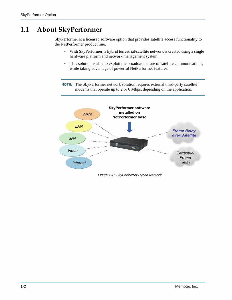
1.1 About SkyPerformerSkyPerformer is a licensed software option that provides satellite access functionality to the NetPerformer product line.
• With SkyPerformer, a hybrid terrestrial/satellite network is created using a single hardware platform and network management system.
• This solution is able to exploit the broadcast nature of satellite communications, while taking advantage of powerful NetPerformer features.
NOTE: The SkyPerformer network solution requires external third-party satellite modems that operate up to 2 or 6 Mbps, depending on the application.
Figure 1-1: SkyPerformer Hybrid Network
1-2 Memotec Inc.
Product Overview
1.2 SkyPerformer FeaturesThe SkyPerformer software is based on Frame Relay standards and offers a scalable solution for both remote and central sites:
• Permits seamless communication with any Frame Relay compliant equipment such as FRADs, routers and switches.
• Goes where terrestrial Frame Relay cannot, providing a cost-effective solution for small to medium sized satellite networks.
• Efficiently consolidates voice, data and LAN traffic with terrestrial Frame Relay networks and equipment.
• Offers a hubless VSAT solution that requires neither an expensive DAMA com-puter nor a central site switch (TDMA).
• Interfaces with all third-party satellite modems.
• Supports a wide variety of satellite network topologies: single or distributed star, partially meshed, point-to-point and multipoint networks.
1.2.1 SkyPerformer versus Point-to-Point Single Channel Per CarrierThe SkyPerformer option offers a superior solution to the point-to-point Single Channel Per Carrier (SCPC) approach:
• SkyPerformer requires fewer satellite carriers. This results in a significant reduc-tion in bandwidth and considerable cost savings.
• It uses less hardware and may dispense with a central site PBX or host, for reduced one-time capital costs.
• It provides better performance:
- Minimizes double-hop satellite delay for voice/data
- Minimizes double compression for voice.
1.2.2 NetPerformer PlatformTo support satellite functionality in a NetPerformer network, the SkyPerformer software is loaded onto each participating NetPerformer product. This means that the SkyPerformer option is able to take advantage of the NetPerformer base software and feature set:
• Integrates SNA, legacy data, LAN traffic, toll-quality analog or digital voice and fax transmissions over a single communication circuit.
• Transmits and receives traffic over public or private Frame Relay or leased line networks for both terrestrial and satellite communications.
• Replaces SNA leased lines with a single Frame Relay connection supporting both PVCs and SVCs.
• Supports IP/IPX/OSPF routing and bridging.
Memotec Inc. 1-3
SkyPerformer Option
• Takes advantage of highly efficient data compression algorithms.
• Adds provision for line failure with Virtual Connections and Dial Backup func-tions.
• Optimizes bandwidth utilization with cell-based multi-protocol prioritization, Bandwidth-On-Demand and Load Balancing.
• Manages the impact of bursty LAN traffic and handles time-sensitive applica-tions with reduced delays.
• Ensures standards compliant interoperability with RFC-1490 and SNMP man-agement.
• Facilitates firmware upgrades through FTP download and proprietary access tools.
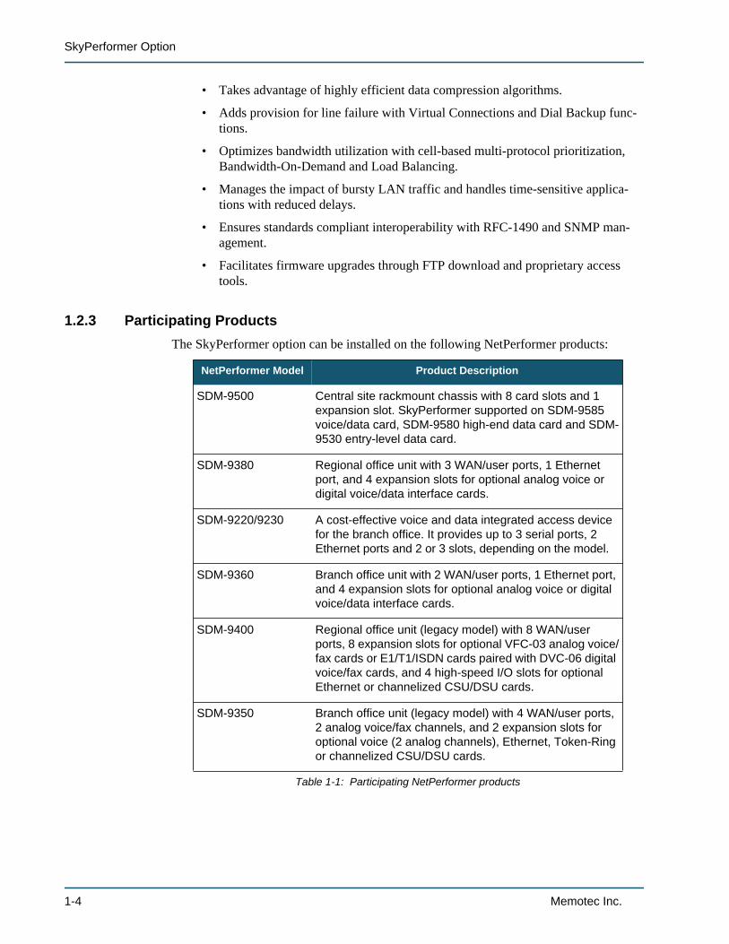
1.2.3 Participating ProductsThe SkyPerformer option can be installed on the following NetPerformer products:
NetPerformer Model Product Description
SDM-9500 Central site rackmount chassis with 8 card slots and 1 expansion slot. SkyPerformer supported on SDM-9585 voice/data card, SDM-9580 high-end data card and SDM-9530 entry-level data card.
SDM-9380 Regional office unit with 3 WAN/user ports, 1 Ethernet port, and 4 expansion slots for optional analog voice or digital voice/data interface cards.
SDM-9220/9230 A cost-effective voice and data integrated access device for the branch office. It provides up to 3 serial ports, 2 Ethernet ports and 2 or 3 slots, depending on the model.
SDM-9360 Branch office unit with 2 WAN/user ports, 1 Ethernet port, and 4 expansion slots for optional analog voice or digital voice/data interface cards.
SDM-9400 Regional office unit (legacy model) with 8 WAN/user ports, 8 expansion slots for optional VFC-03 analog voice/fax cards or E1/T1/ISDN cards paired with DVC-06 digital voice/fax cards, and 4 high-speed I/O slots for optional Ethernet or channelized CSU/DSU cards.
SDM-9350 Branch office unit (legacy model) with 4 WAN/user ports, 2 analog voice/fax channels, and 2 expansion slots for optional voice (2 analog channels), Ethernet, Token-Ring or channelized CSU/DSU cards.
Table 1-1: Participating NetPerformer products
1-4 Memotec Inc.
Product Overview
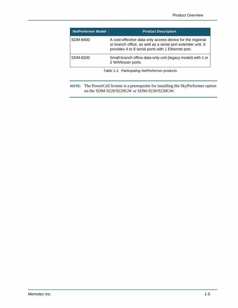
NOTE: The PowerCell license is a prerequisite for installing the SkyPerformer option on the SDM-9220/9220GW or SDM-9230/9230GW.
SDM-8400 A cost-effective data only access device for the regional or branch office, as well as a serial port extender unit. It provides 4 to 8 serial ports with 1 Ethernet port.
SDM-8200 Small branch office data-only unit (legacy model) with 1 or 2 WAN/user ports.
NetPerformer Model Product Description
Table 1-1: Participating NetPerformer products
Memotec Inc. 1-5
SkyPerformer Option
1.3 Network Topologies SupportedSkyPerformer supports three main types of satellite networks:
• Single star
• Distributed star
• Partial mesh
• Full mesh.
1-6 Memotec Inc.
Product Overview
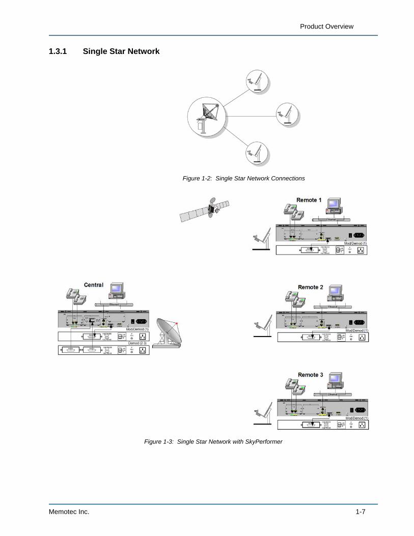
1.3.1 Single Star Network
Figure 1-2: Single Star Network Connections
Figure 1-3: Single Star Network with SkyPerformer
Memotec Inc. 1-7
SkyPerformer Option
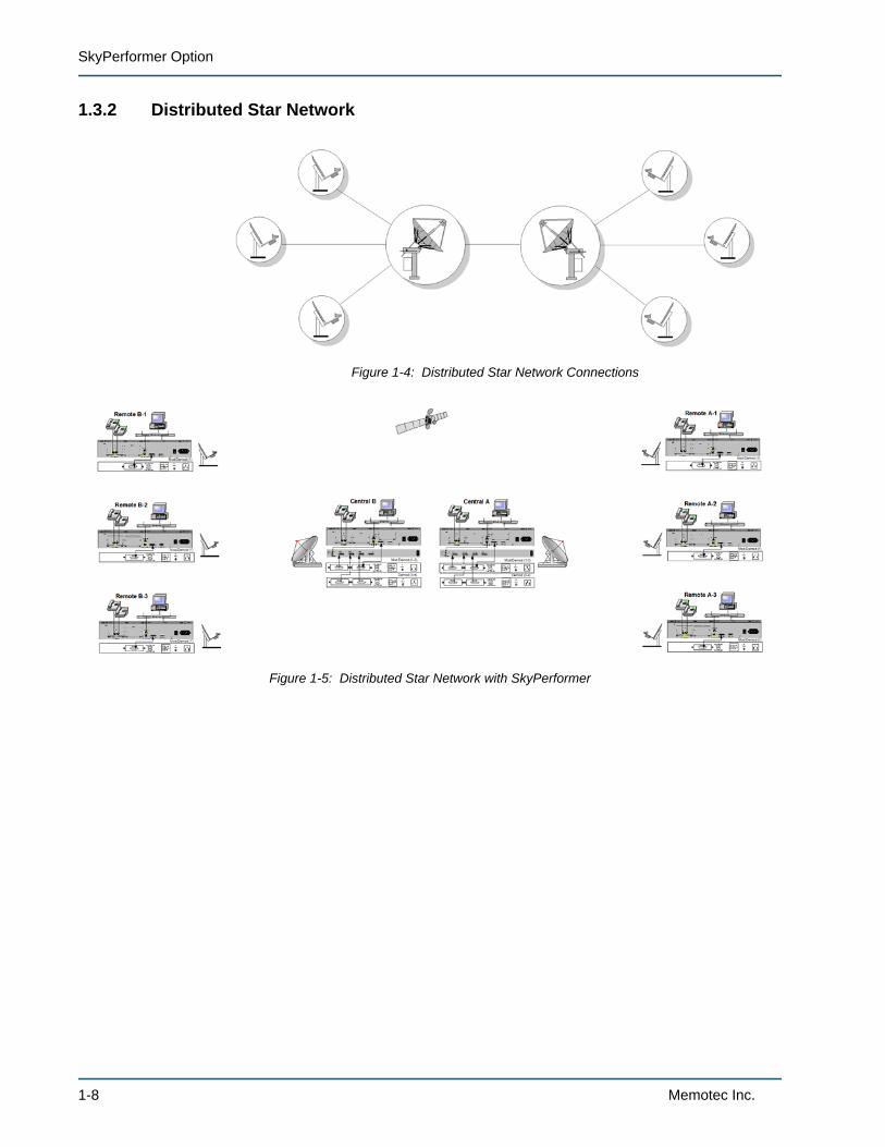
1.3.2 Distributed Star Network
Figure 1-4: Distributed Star Network Connections
Figure 1-5: Distributed Star Network with SkyPerformer
1-8 Memotec Inc.
Product Overview
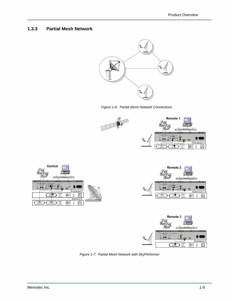
1.3.3 Partial Mesh Network
Figure 1-6: Partial Mesh Network Connections
Figure 1-7: Partial Mesh Network with SkyPerformer
Memotec Inc. 1-9
SkyPerformer Option
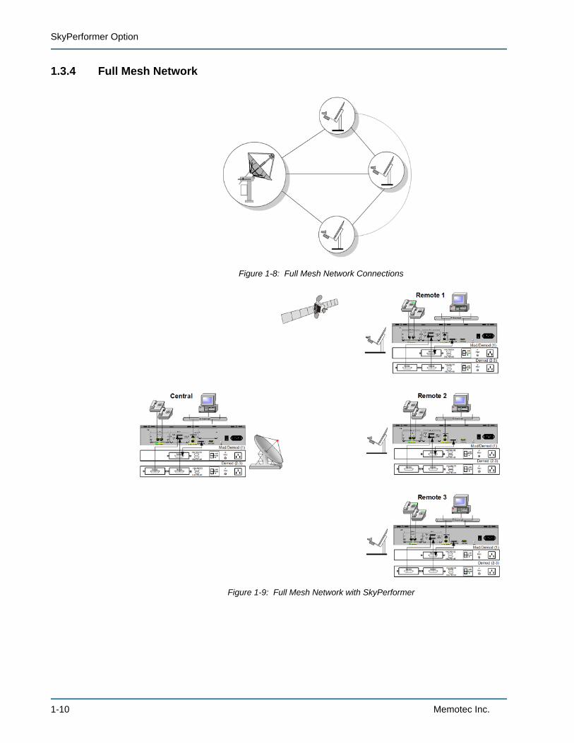
1.3.4 Full Mesh Network
Figure 1-8: Full Mesh Network Connections
Figure 1-9: Full Mesh Network with SkyPerformer
1-10 Memotec Inc.
Product Overview
1.4 Typical SkyPerformer ApplicationsSkyPerformer has been designed to handle the following networks:
• Hybrid terrestrial/satellite networks with a mix of voice and data
• Networks that start small and need to grow. SkyPerformer and the NetPerformer provide modular expansion capabilities.
• Multiplexer/SCPC modem networks, especially for multipoint applications
• Small to medium-sized enterprise networks:
- Star networks with up to 350 sites
- Distributed star networks with unlimited sites
- Mesh networks with up to 50 sites.
In particular, SkyPerformer is ideal for the following applications:
• Voice/data enterprise solutions via satellite (see Figure 1-10)
• E1/T1 voice trunking via satellite (see Figure 1-11)
• Internet backbone extension via satellite (see Figure 1-12)
• Public network extension via satellite (see Figure 1-13).
NOTE: An example application, with a screen dump of the console configuration it requires, is provided in “Example Application” on page 5-1.
Memotec Inc. 1-11
SkyPerformer Option
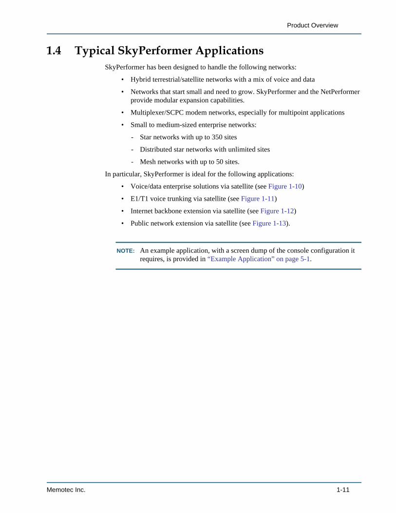
1.4.1 Voice/data Enterprise NetworksIn this application all NetPerformer units in the enterprise network communicate via satellite connection using the SkyPerformer software.
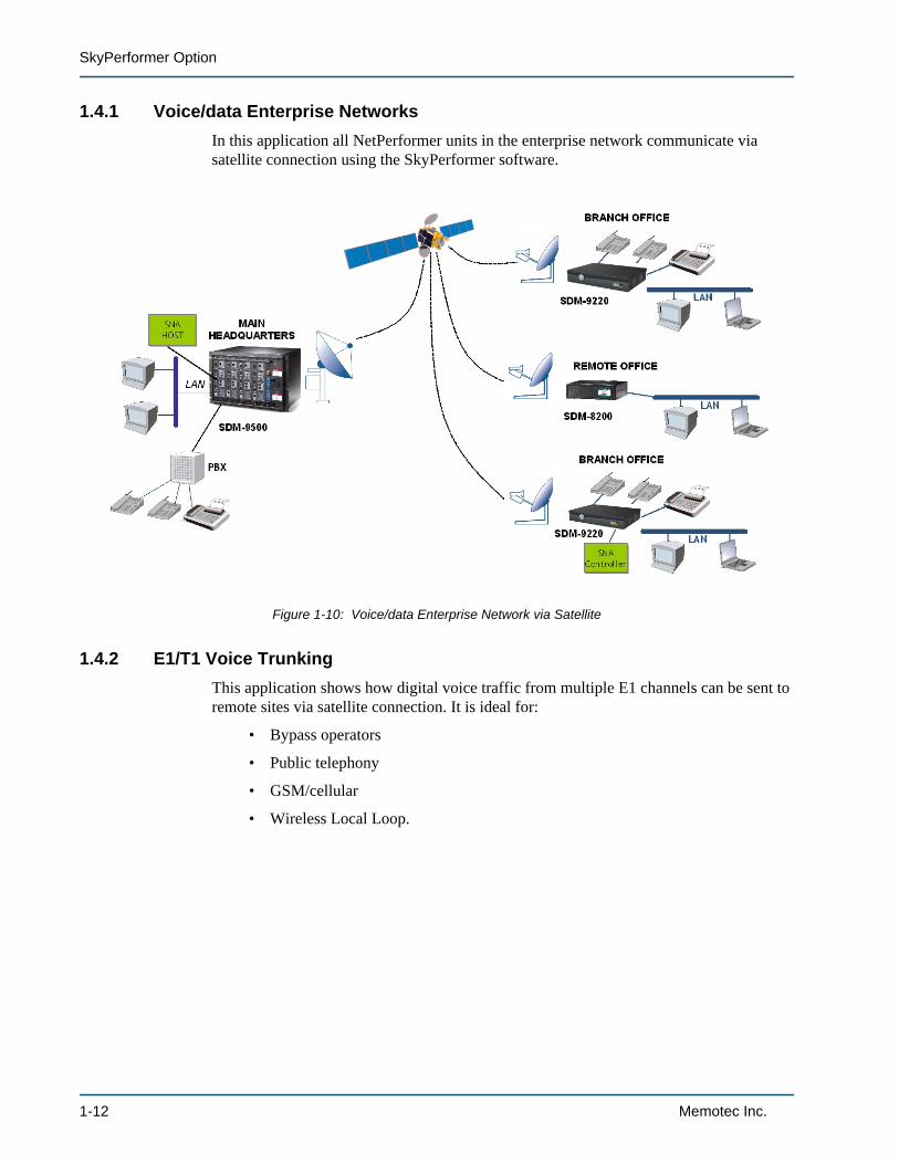
1.4.2 E1/T1 Voice TrunkingThis application shows how digital voice traffic from multiple E1 channels can be sent to remote sites via satellite connection. It is ideal for:
• Bypass operators
• Public telephony
• GSM/cellular
• Wireless Local Loop.
Figure 1-10: Voice/data Enterprise Network via Satellite
1-12 Memotec Inc.
Product Overview
Figure 1-11: E1/T1 Voice Trunking via Satellite
Memotec Inc. 1-13
SkyPerformer Option
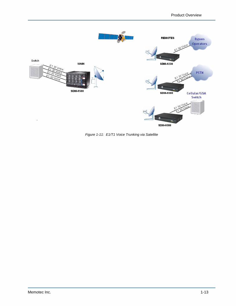
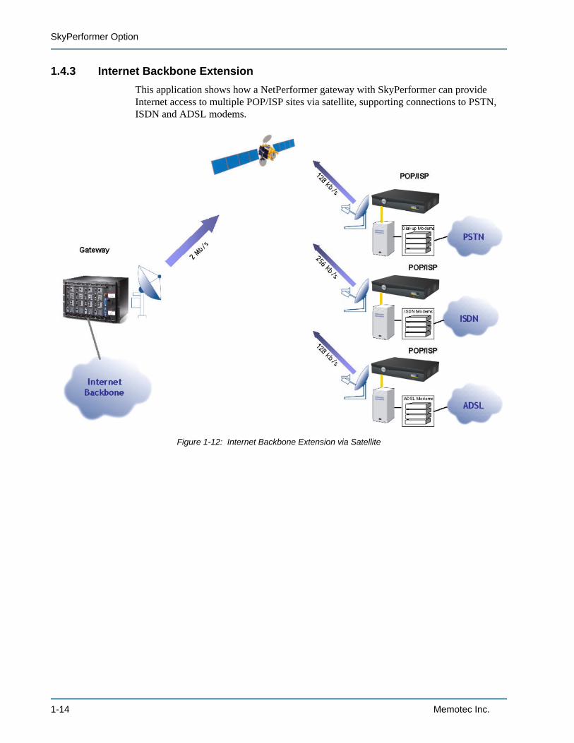
1.4.3 Internet Backbone ExtensionThis application shows how a NetPerformer gateway with SkyPerformer can provide Internet access to multiple POP/ISP sites via satellite, supporting connections to PSTN, ISDN and ADSL modems.
Figure 1-12: Internet Backbone Extension via Satellite
1-14 Memotec Inc.
Product Overview
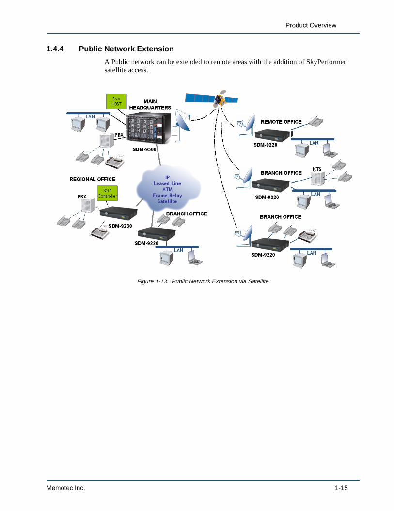
1.4.4 Public Network ExtensionA Public network can be extended to remote areas with the addition of SkyPerformer satellite access.
Figure 1-13: Public Network Extension via Satellite
Memotec Inc. 1-15
SkyPerformer Option
1.5 Theory of Operation
1.5.1 Transmission to Remote Sites
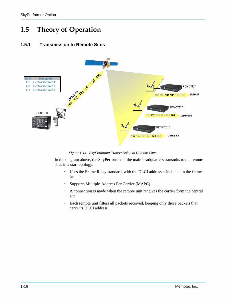
In the diagram above, the SkyPerformer at the main headquarters transmits to the remote sites in a star topology.
• Uses the Frame Relay standard, with the DLCI addresses included in the frame headers
• Supports Multiple-Address Per Carrier (MAPC)
• A connection is made when the remote unit receives the carrier from the central site
• Each remote unit filters all packets received, keeping only those packets that carry its DLCI address.
Figure 1-14: SkyPerformer Transmission to Remote Sites
1-16 Memotec Inc.
Product Overview
1.5.2 Reception at Main Headquarters
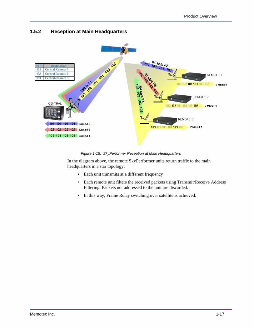
In the diagram above, the remote SkyPerformer units return traffic to the main headquarters in a star topology.
• Each unit transmits at a different frequency
• Each remote unit filters the received packets using Transmit/Receive Address Filtering. Packets not addressed to the unit are discarded.
• In this way, Frame Relay switching over satellite is achieved.
Figure 1-15: SkyPerformer Reception at Main Headquarters
Memotec Inc. 1-17
SkyPerformer Option
1.5.3 Intra-network Transmissions
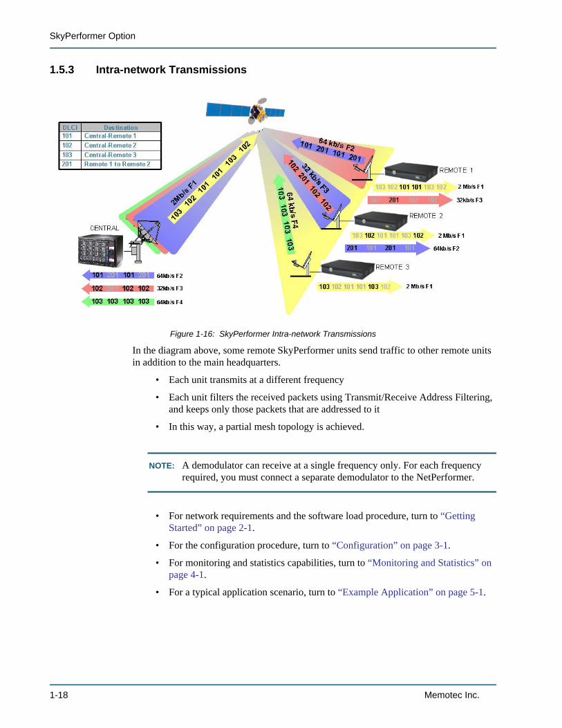
In the diagram above, some remote SkyPerformer units send traffic to other remote units in addition to the main headquarters.
• Each unit transmits at a different frequency
• Each unit filters the received packets using Transmit/Receive Address Filtering, and keeps only those packets that are addressed to it
• In this way, a partial mesh topology is achieved.
NOTE: A demodulator can receive at a single frequency only. For each frequency required, you must connect a separate demodulator to the NetPerformer.
• For network requirements and the software load procedure, turn to “Getting Started” on page 2-1.
• For the configuration procedure, turn to “Configuration” on page 3-1.
• For monitoring and statistics capabilities, turn to “Monitoring and Statistics” on page 4-1.
• For a typical application scenario, turn to “Example Application” on page 5-1.
Figure 1-16: SkyPerformer Intra-network Transmissions
1-18 Memotec Inc.

2
Getting StartedMemotec Inc. 2-1
SkyPerformer Option
2.1 Preparing the SiteThis chapter offers some helpful hints for site preparation, network planning and activating the software license. A general power-up procedure is provided at the end of this chapter.
2.1.1 UnpackingAs soon as you receive the SkyPerformer product package, check the package and its contents for any sign of damage during shipment. If there is any damage, contact the shipping agent immediately.
Verify the contents of the SkyPerformer package to ensure that you have received a complete shipment, which includes the following items:
• Software License Key label on package cover
• SkyPerformer product license
• This guide.
If any of these items are missing, or if you have any questions concerning your shipment, please contact your NetPerformer distributor.
2.1.2 What You Will NeedFor trouble-free product installation you should have the following items on hand:
• The SkyPerformer product package, including the Software License Key.
• The NetPerformer unit that will serve as the main chassis.
• (Optional) One or more additional NetPerformer units that will serve as expan-sion chassis, if required.
• Third party external satellite modems. These modems are required for modula-tion/demodulation between the SkyPerformer and the earth station. They typi-cally have the following characteristics:
- IF frequency: 52-88 MHz, 104-176 Mhz or 950-1450 MHz
- Modulation: BPSK or QPSK
- FEC: Rate 1/2, 3/4, 7/8 convolutional encoding, Viterbi decoding
NOTE: SkyPerformer transmissions are independent of these modem frequencies, modulation and FEC, since the NetPerformer chassis connects to the external satellite modem using a V.35 or other type of serial connection.
- Bit rate: 9.6 Kbps to 2 or 6 Mbps, depending on the application.
• A configuration and management access device, either:
2-2 Memotec Inc.
Getting Started
- A console terminal (TTY terminal or a PC equipped with terminal emulation software) for direct or dial-up connection to the console port at the rear of the NetPerformer unit,
- A TELNET network device accessed through IP connectivity over LAN/WAN, or
- An SNMP agent accessed through IP connectivity over LAN/WAN.
NOTE: If the NetPerformer unit still has its factory configuration, the only configura-tion device that will work is the console terminal, since the unit does not yet have an IP address.
• All user equipment that will be directly connected to the SkyPerformer ports. This includes external satellite modems for communication to (modulators) and from (demodulators) the earth station.
• A sufficient number and length of cables. Refer to the Hardware Installation Guide for the specific product (or Quick Setup Guide, for legacy products). Also refer to page 6 of this document for a table of required physical connections.
Memotec Inc. 2-3
SkyPerformer Option
2.2 Network DiagramBefore you install the SkyPerformer software and connect the NetPerformer to your satellite equipment, you should have a clear idea of how you want to design your network. To do this, create a network diagram:
1. Draw a diagram of your proposed physical network. This diagram will prove useful when configuring the SkyPerformer or making later modifications to your network.
2. Determine what naming convention you will use to distinguish this SkyPerformer from all other NetPerformer units in your network. We suggest that you name each unit according to its location, to reflect the physical network structure. Write all unit names on the network diagram.
3. Next to each SkyPerformer unit, make a list of all equipment you want to support at each site. A main chassis can have:
• One MODULATOR port for connection to an external modulator (TX satellite modem). The modulator transmits packets to the satellite.
• One or more DEMODULATOR ports for connection to an external demodulator (RX satellite modem). The demodulator decodes the packets that the satellite sends to earth. The maximum number of DEMODULATOR ports is determined by the number of data ports available on the NetPerformer unit.
NOTE: Traffic from the DEMODULATOR ports on one NetPerformer unit can be sent to a MODULATOR port on another unit using SP-MULTIPLEX PVCs. Refer to Configuring the Logical Layer (PVCs) on page 10.
4. An optional expansion chassis can have:
• One or more DEMODULATOR ports for connection to an external demodulator. The maximum number is determined by the number of data ports available on the unit.
5. If the NetPerformer unit has not been previously configured for the other network equipment, determine:
• For the voice connections: all speed dial numbers, extension numbers, interfaces, speeds, line activation types, IP addresses, ring voltage, ring frequency and any other information relevant to your network setup.
• For the data connections: the required protocol, line speed, port interface and gender (DTE/DCE). If an SNA/SDLC application, all controller (PU) numbers and addresses, and all primary and secondary connections to the NetPerformer unit. If a Frame Relay application, all PVC numbers, operating modes, DLCI addresses, SVC network addresses, CIR and BIR.
• For the LAN connections: all required IP and/or network addresses, required interfaces and speeds.
2-4 Memotec Inc.
Getting Started
• For the T1/E1 connections: timeslot usage, operating protocols for data/voice channels.
Annotate the network diagram with this information. Keep in mind the number of voice, WAN/user, LAN, T1/E1, PVC and PU connections permitted on each unit (refer to the Hardware Installation Guide for the specific NetPerformer product).
6. Determine the priority level of each traffic type in your network:
• To avoid response time problems and session timeouts, delay sensitive protocols such as LLC2 or SDLC can be assigned a high priority.
• Voice/fax traffic is given high-priority status by default, due to its time-sensitive nature. You can change this priority to a lower level, if desired.
• For LAN/legacy traffic, the way the available bandwidth will be partitioned depends on the way you configure the class assignments, the relative class weights and specific data filters.
Annotate the network diagram with an indication of relative traffic priority lev-els.
Memotec Inc. 2-5

SkyPerformer Option
2.3 Physical ConnectionsThis section addresses installation requirements that are specific to a SkyPerformer network. Full installation instructions for the NetPerformer unit can be found in the Hardware Installation Guide for that product (or Quick Setup Guide for a legacy product).
These documents are available on the NetPerformer Online Reference CD, which is included with each NetPerformer product package.
In addition to the installation requirements for the NetPerformer unit, a SkyPerformer application requires the physical connections described in Table 2-1.
NOTE: Use standard cables (certain interfaces and NetPerformer products only) or custom-made cables available from Memotec Inc.. Supported interfaces include RS-232, V.35/V.11,V.35 CE, X.21/V.11, RS-449/422 and RS-530.
2.3.1 Installation Tips• Usually, each NetPerformer unit will have one connection to a modulator, and
another connection to a demodulator. This provides full duplex transmission via satellite.
• Physical cabling between NetPerformer units is not required. All connections between nodes are made using SP-MULTIPLEX PVCs.
• A modulator broadcasts on one frequency, which can be received by more than one remote unit.
• A demodulator can receive a single frequency only. For the central site unit, you will require the same number of demodulators as there are remote units.
Function of the Connection
SkyPerformer Port Type To External Device Cable Gender
Transmits packets to the sat-ellite modulator
MODULATOR Modulator (TX sat-ellite modem) or modem (Modula-tor and Demodula-tor)
DTE
Receives the packets from the satellite demodulator
DEMODULATOR Demodulator (RX satellite modem)
DTE
Table 2-1: SkyPerformer cable connections
2-6 Memotec Inc.
Getting Started
2.4 Software LicenseImportant: The SkyPerformer option includes a Software Licensing Agreement, which can be found in the product package.
• You must agree to the terms and conditions of this agreement before loading the software.
• Each NetPerformer unit in the SkyPerformer application requires a sepa-rate software license.
• SDM-9500 units that are linked with an expansion card are considered as one unit, since they are part of the same chassis system.
• The PowerCell license is a prerequisite for installing the SkyPerformer option on the SDM-9220/9220GW or SDM-9230/9230GW.
2.4.1 Before You ConfigureThe SkyPerformer software must be activated on the NetPerformer unit before you can configure and use any SkyPerformer features. This requires entering the SkyPerformer Software License to the License Profile.
NOTE: A specific License Profile is valid for a single NetPerformer unit only.
To prepare for SkyPerformer configuration you must first:
• Install the NetPerformer unit according to the instructions given in the Hard-ware Installation Guide for the particular product, which is available on the NetPerformer Documentation CD (Part No. 161-0692-001).
• Install and activate the SkyPerformer Option software license, following the pro-cedure provided in the Software Licensing chapter of the Software Installa-tion and Licensing fascicle of this document series.
• At any time, you can reset the unit configuration to its factory defaults: enter FS at the command prompt. The SkyPerformer Option is reset along with all other areas of the configuration, and all previously defined values are lost.
When you execute the FS command, the NetPerformer unit clears its License Profile and turns off all data ports that were configured for SkyPerformer opera-tion (port protocol set to SP). You must:
- Re-enter the SkyPerformer Option software license, and
- Change the Protocol parameter on all ports involved in the application to SP (see Setting the Port Protocol on page 2).
2.4.2 Is the SkyPerformer Option Already Installed?To determine whether a NetPerformer unit is already installed with the SkyPerformer
Memotec Inc. 2-7
SkyPerformer Option
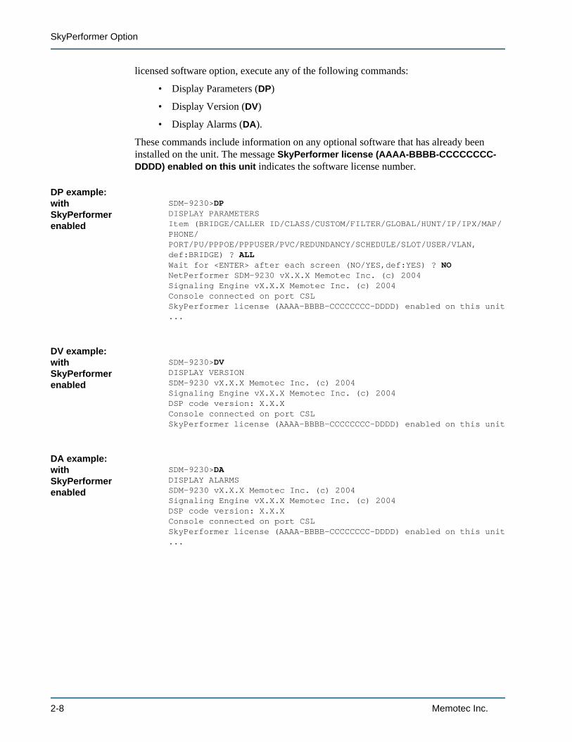
licensed software option, execute any of the following commands:
• Display Parameters (DP)
• Display Version (DV)
• Display Alarms (DA).
These commands include information on any optional software that has already been installed on the unit. The message SkyPerformer license (AAAA-BBBB-CCCCCCCC-DDDD) enabled on this unit indicates the software license number.
DP example: with SkyPerformer enabled
SDM-9230>DPDISPLAY PARAMETERSItem (BRIDGE/CALLER ID/CLASS/CUSTOM/FILTER/GLOBAL/HUNT/IP/IPX/MAP/PHONE/PORT/PU/PPPOE/PPPUSER/PVC/REDUNDANCY/SCHEDULE/SLOT/USER/VLAN,def:BRIDGE) ? ALLWait for <ENTER> after each screen (NO/YES,def:YES) ? NONetPerformer SDM-9230 vX.X.X Memotec Inc. (c) 2004Signaling Engine vX.X.X Memotec Inc. (c) 2004Console connected on port CSLSkyPerformer license (AAAA-BBBB-CCCCCCCC-DDDD) enabled on this unit...
DV example: with SkyPerformer enabled
SDM-9230>DVDISPLAY VERSIONSDM-9230 vX.X.X Memotec Inc. (c) 2004Signaling Engine vX.X.X Memotec Inc. (c) 2004DSP code version: X.X.XConsole connected on port CSLSkyPerformer license (AAAA-BBBB-CCCCCCCC-DDDD) enabled on this unit
DA example: with SkyPerformer enabled
SDM-9230>DADISPLAY ALARMSSDM-9230 vX.X.X Memotec Inc. (c) 2004Signaling Engine vX.X.X Memotec Inc. (c) 2004DSP code version: X.X.XConsole connected on port CSLSkyPerformer license (AAAA-BBBB-CCCCCCCC-DDDD) enabled on this unit...
2-8 Memotec Inc.
Getting Started
2.5 Power-up SequenceDue to hardware differences, the power-up sequence differs slightly from one NetPerformer product to the next. For details, refer to the Hardware Installation Guide for your particular product (or Quick Setup Guide, for legacy NetPerformer products).
In general, the power-up procedure includes the following steps:
1. Connect the factory supplied power cord to the AC inlet.
2. Plug the other end of the power cord into an AC power outlet (100-240 VAC, 50/60 Hz).
3. On units with a power switch, power up the unit by pushing the power switch to the 1 position (ON).
4. On power-up the NetPerformer unit executes program decompression and system test. Follow the system status LED displays.
5. If you are using a console terminal, plug it into the console port using an RS-232/V.24 cable, and power it on.
6. Access the console by pressing the Enter key at least three times.
7. Configure all SkyPerformer parameters and options.
8. Once you have configured the data ports you can connect the cables from these ports to the Frame Relay devices. Voice ports can be configured before or after cable connection.
9. Activate a data port by bringing up the connected user equipment.
10. Activate a voice port by dialing a speed dial number to place a call.
11. Check the status of the NetPerformer unit, its connections and all active ports, PUs and PVCs by executing the statistics commands. Commands specifically used for the SkyPerformer are described in “Monitoring and Statistics” on page 4-1.
Memotec Inc. 2-9

SkyPerformer Option
2-10 Memotec Inc.
3
ConfigurationMemotec Inc. 3-1
SkyPerformer Option
3.1 Configuring SkyPerformer LinksThis chapter addresses configuration requirements for the SkyPerformer option only. Parameters and commands for configuring other NetPerformer functions are described in the other fascicles of this document series.
NOTE: Turn to the section “Before You Configure” on page 2-7 for important infor-mation prior to setting up your SkyPerformer network.
Each data port that connects to an external modulator or demodulator must be configured as a SkyPerformer satellite link. In a SkyPerformer application a satellite link can be configured on:
• A serial port, including built-in ports and ports on a Dual Serial Port interface card installed in the unit chassis
• A digital channel on a T1 or E1 interface card.
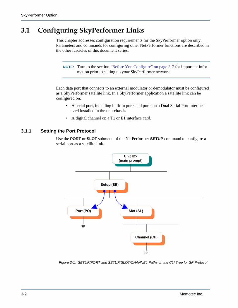
3.1.1 Setting the Port ProtocolUse the PORT or SLOT submenu of the NetPerformer SETUP command to configure a serial port as a satellite link.
Figure 3-1: SETUP/PORT and SETUP/SLOT/CHANNEL Paths on the CLI Tree for SP Protocol
3-2 Memotec Inc.
Configuration
Built-in Serial Port
To configure a SkyPerformer link on a built-in serial port:
1. At the main command line prompt on the console, enter the menu sequence: SE PORT
2. Select the Port number
On some legacy NetPerformer models, you may need to specify DATA as the port type before you can select the port number
3. Set the Protocol to SP
4. Set the port Type to MODULATOR or DEMODULATOR.
The main chassis requires one or more MODULATOR ports. All remaining ports can be defined as DEMODULATOR. See “Setting the Port Type” on page 3-5 for details.
5. Change the other port parameters from their default values, if desired.
Serial Port on Dual Serial Interface Card
To configure a SkyPerformer link on a serial port on the Dual Serial interface card:
1. At the main command line prompt on the console, enter the menu sequence: SE SLOT
2. Select the Slot number
3. Select the Channel number
4. Set the Protocol to SP
5. Set the port Type to MODULATOR or DEMODULATOR. See “Setting the Port Type” on page 3-5 for details.
6. Change the other port parameters from their default values, if desired.
Digital Channel on T1 or E1 Interface Card
NOTE: To configure the physical port (LINK) of the T1 or E1 interface card, set the Signaling mode to NONE. Details on LINK configuration are provided in the chapter Configuring Digital Data Connections in the Digital Data fasci-cle of this document series.
To configure a SkyPerformer link on a digital channel:
1. At the main command line prompt on the console, enter the menu sequence: SE SLOT
2. Select the Slot number
3. Enter CHANNEL
Memotec Inc. 3-3
SkyPerformer Option
4. Select the Channel Number, e.g. 102, where the first digit indicates the slot and the last two digits indicate the channel.
5. Set the Protocol to SP
6. Select the Timeslot and Number of consecutive timeslots to be used for this connection
7. Set the port Type to MODULATOR or DEMODULATOR. See “Setting the Port Type” on page 3-5 for details.
8. Change the other port parameters from their default values, if desired.
SE/SLOT/#/CHANNEL example
9230-1>SESETUPItem (BRIDGE/CALLER ID/CLASS/CUSTOM/FILTER/GLOBAL/HUNT/IP/IPX/MAP/PHONE/PORT/PU/PPPOE/PPPUSER/PVC/REDUNDANCY/SCHEDULE/SLOT/USER/VLAN,def:SLOT) ? SLOTSLOT> Slot number (1/2,def:1) ?Item (LINK/CHANNEL,def:LINK) ? CHANNELSLOT> Channel Number (101-124/ALL,def:101) ? 101PORT 101> Protocol (def:PVCR) ? SPPORT 101> Timeslot (def:1) ?PORT 101> Number of consecutive timeslots (1-24,def:12) ? 4PORT 101> Type (def:DEMODULATOR) ? MODULATORPORT 101> DS0 speed (bps).......................64000PORT 101> Cell Packetization (def:YES) ?PORT 101> Congestion flow control (def:ON) ?PORT 101> CLLM function (def:OFF) ?PORT 101> Maximum number of voice channels (0-10000,def:10000) ?PORT 101> Maximum Voice Channels If High Priority Data (0-10000,def:10000) ?
3-4 Memotec Inc.
Configuration
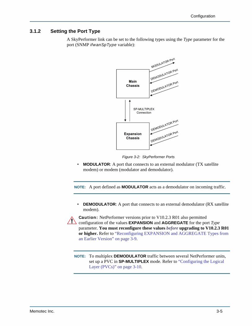
3.1.2 Setting the Port TypeA SkyPerformer link can be set to the following types using the Type parameter for the port (SNMP ifwanSpType variable):
• MODULATOR: A port that connects to an external modulator (TX satellite modem) or modem (modulator and demodulator).
NOTE: A port defined as MODULATOR acts as a demodulator on incoming traffic.
• DEMODULATOR: A port that connects to an external demodulator (RX satellite modem).
Caution: NetPerformer versions prior to V10.2.3 R01 also permitted configuration of the values EXPANSION and AGGREGATE for the port Type parameter. You must reconfigure these values before upgrading to V10.2.3 R01 or higher. Refer to “Reconfiguring EXPANSION and AGGREGATE Types from an Earlier Version” on page 3-9.
NOTE: To multiplex DEMODULATOR traffic between several NetPerformer units, set up a PVC in SP-MULTIPLEX mode. Refer to “Configuring the Logical Layer (PVCs)” on page 3-10.
Figure 3-2: SkyPerformer Ports
Memotec Inc. 3-5
SkyPerformer Option
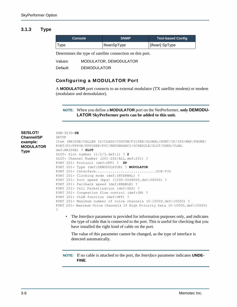
3.1.3 Type
Determines the type of satellite connection on this port.
Configuring a MODULATOR Port
A MODULATOR port connects to an external modulator (TX satellite modem) or modem (modulator and demodulator).
NOTE: When you define a MODULATOR port on the NetPerformer, only DEMODU-LATOR SkyPerformer ports can be added to this unit.
SE/SLOT/Channel/SP example: MODULATOR Type
SDM-9230>SESETUPItem (BRIDGE/CALLER ID/CLASS/CUSTOM/FILTER/GLOBAL/HUNT/IP/IPX/MAP/PHONE/PORT/PU/PPPOE/PPPUSER/PVC/REDUNDANCY/SCHEDULE/SLOT/USER/VLAN,def:BRIDGE) ? SLOTSLOT> Slot number (1/2/3,def:1) ? 2SLOT> Channel Number (201-202/ALL,def:201) ?PORT 201> Protocol (def:OFF) ? SPPORT 201> Type (def:DEMODULATOR) ? MODULATORPORT 201> Interface.............................DCE-V35PORT 201> Clocking mode (def:INTERNAL) ?PORT 201> Port speed (bps) (1200-2048000,def:56000) ?PORT 201> Fallback speed (def:ENABLE) ? PORT 201> Cell Packetization (def:YES) ? PORT 201> Congestion flow control (def:ON) ? PORT 201> CLLM function (def:OFF) ? PORT 201> Maximum number of voice channels (0-10000,def:10000) ?PORT 201> Maximum Voice Channels If High Priority Data (0-10000,def:10000) ?
• The Interface parameter is provided for information purposes only, and indicates the type of cable that is connected to the port. This is useful for checking that you have installed the right kind of cable on the port.
The value of this parameter cannot be changed, as the type of interface is detected automatically.
NOTE: If no cable is attached to the port, the Interface parameter indicates UNDE-FINE.
Console SNMP Text-based Config
Type ifwanSpType [ifwan] SpType
Values: MODULATOR, DEMODULATOR
Default: DEMODULATOR
3-6 Memotec Inc.
Configuration
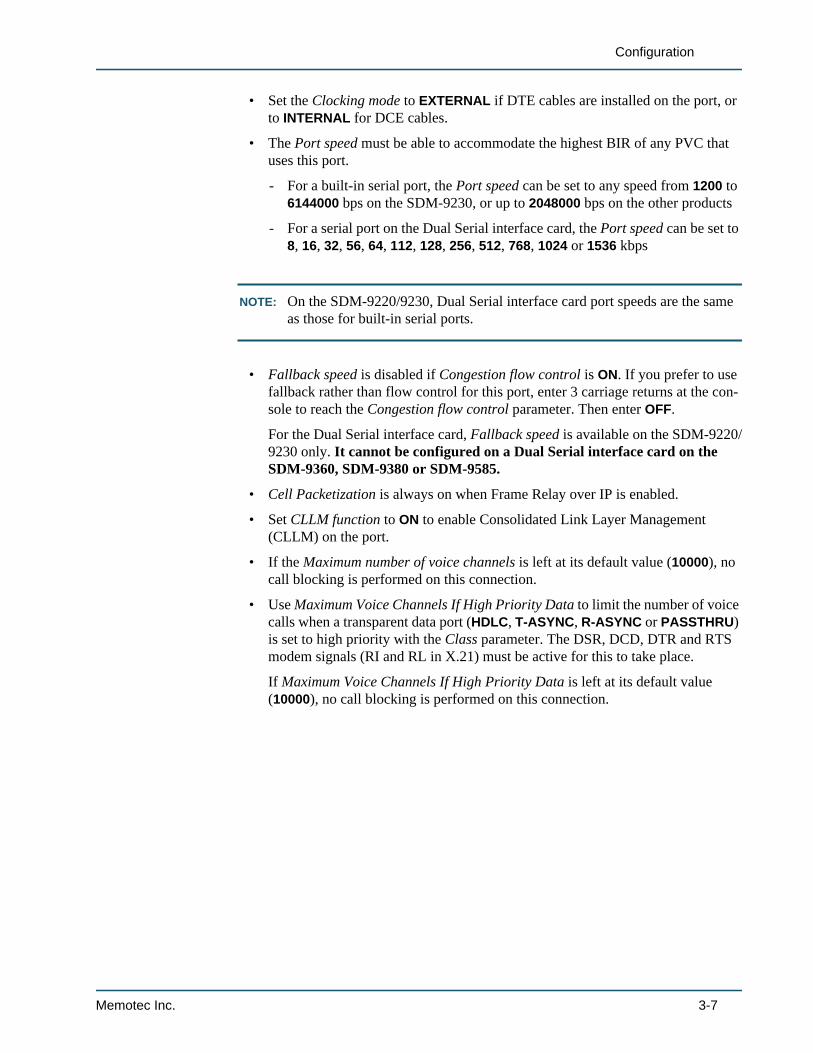
• Set the Clocking mode to EXTERNAL if DTE cables are installed on the port, or to INTERNAL for DCE cables.
• The Port speed must be able to accommodate the highest BIR of any PVC that uses this port.
- For a built-in serial port, the Port speed can be set to any speed from 1200 to 6144000 bps on the SDM-9230, or up to 2048000 bps on the other products
- For a serial port on the Dual Serial interface card, the Port speed can be set to 8, 16, 32, 56, 64, 112, 128, 256, 512, 768, 1024 or 1536 kbps
NOTE: On the SDM-9220/9230, Dual Serial interface card port speeds are the same as those for built-in serial ports.
• Fallback speed is disabled if Congestion flow control is ON. If you prefer to use fallback rather than flow control for this port, enter 3 carriage returns at the con-sole to reach the Congestion flow control parameter. Then enter OFF.
For the Dual Serial interface card, Fallback speed is available on the SDM-9220/9230 only. It cannot be configured on a Dual Serial interface card on the SDM-9360, SDM-9380 or SDM-9585.
• Cell Packetization is always on when Frame Relay over IP is enabled.
• Set CLLM function to ON to enable Consolidated Link Layer Management (CLLM) on the port.
• If the Maximum number of voice channels is left at its default value (10000), no call blocking is performed on this connection.
• Use Maximum Voice Channels If High Priority Data to limit the number of voice calls when a transparent data port (HDLC, T-ASYNC, R-ASYNC or PASSTHRU) is set to high priority with the Class parameter. The DSR, DCD, DTR and RTS modem signals (RI and RL in X.21) must be active for this to take place.
If Maximum Voice Channels If High Priority Data is left at its default value (10000), no call blocking is performed on this connection.
Memotec Inc. 3-7
SkyPerformer Option
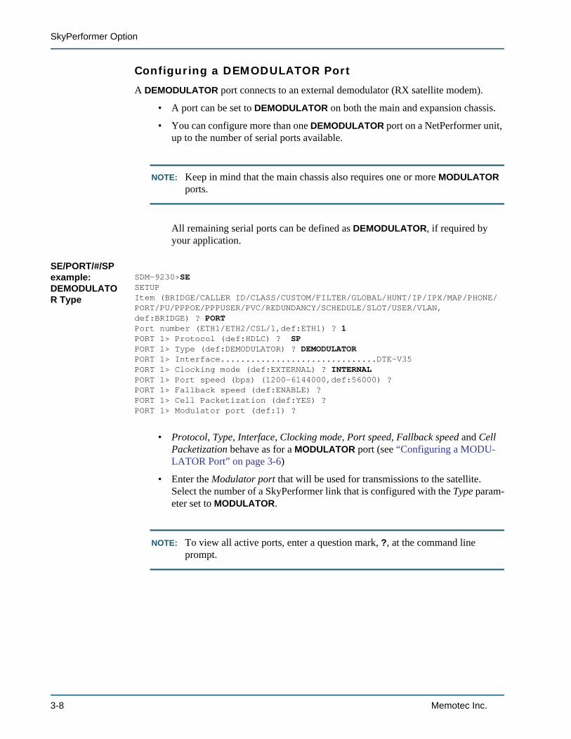
Configuring a DEMODULATOR Port
A DEMODULATOR port connects to an external demodulator (RX satellite modem).
• A port can be set to DEMODULATOR on both the main and expansion chassis.
• You can configure more than one DEMODULATOR port on a NetPerformer unit, up to the number of serial ports available.
NOTE: Keep in mind that the main chassis also requires one or more MODULATOR ports.
All remaining serial ports can be defined as DEMODULATOR, if required by your application.
SE/PORT/#/SP example: DEMODULATOR Type
SDM-9230>SESETUPItem (BRIDGE/CALLER ID/CLASS/CUSTOM/FILTER/GLOBAL/HUNT/IP/IPX/MAP/PHONE/PORT/PU/PPPOE/PPPUSER/PVC/REDUNDANCY/SCHEDULE/SLOT/USER/VLAN,def:BRIDGE) ? PORTPort number (ETH1/ETH2/CSL/1,def:ETH1) ? 1PORT 1> Protocol (def:HDLC) ? SPPORT 1> Type (def:DEMODULATOR) ? DEMODULATORPORT 1> Interface...............................DTE-V35PORT 1> Clocking mode (def:EXTERNAL) ? INTERNALPORT 1> Port speed (bps) (1200-6144000,def:56000) ?PORT 1> Fallback speed (def:ENABLE) ?PORT 1> Cell Packetization (def:YES) ?PORT 1> Modulator port (def:1) ?
• Protocol, Type, Interface, Clocking mode, Port speed, Fallback speed and Cell Packetization behave as for a MODULATOR port (see “Configuring a MODU-LATOR Port” on page 3-6)
• Enter the Modulator port that will be used for transmissions to the satellite. Select the number of a SkyPerformer link that is configured with the Type param-eter set to MODULATOR.
NOTE: To view all active ports, enter a question mark, ?, at the command line prompt.
3-8 Memotec Inc.
Configuration
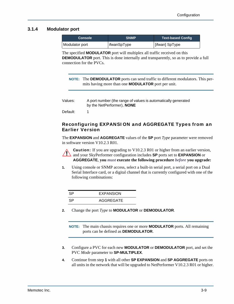
3.1.4 Modulator port
The specified MODULATOR port will multiplex all traffic received on this DEMODULATOR port. This is done internally and transparently, so as to provide a full connection for the PVCs.
NOTE: The DEMODULATOR ports can send traffic to different modulators. This per-mits having more than one MODULATOR port per unit.
Reconfiguring EXPANSION and AGGREGATE Types from an Earlier Version
The EXPANSION and AGGREGATE values of the SP port Type parameter were removed in software version V10.2.3 R01.
Caution: If you are upgrading to V10.2.3 R01 or higher from an earlier version, and your SkyPerformer configuration includes SP ports set to EXPANSION or AGGREGATE, you must execute the following procedure before you upgrade:
1. Using console or SNMP access, select a built-in serial port, a serial port on a Dual Serial Interface card, or a digital channel that is currently configured with one of the following combinations:
2. Change the port Type to MODULATOR or DEMODULATOR.
NOTE: The main chassis requires one or more MODULATOR ports. All remaining ports can be defined as DEMODULATOR.
3. Configure a PVC for each new MODULATOR or DEMODULATOR port, and set the PVC Mode parameter to SP-MULTIPLEX.
4. Continue from step 1 with all other SP EXPANSION and SP AGGREGATE ports on all units in the network that will be upgraded to NetPerformer V10.2.3 R01 or higher.
Console SNMP Text-based Config
Modulator port ifwanSpType [ifwan] SpType
Values: A port number (the range of values is automatically generated by the NetPerformer), NONE
Default: 1
Protocol Type
SP EXPANSION
SP AGGREGATE
Memotec Inc. 3-9
SkyPerformer Option
3.2 Configuring the Logical Layer (PVCs)A PVC provides a logical path between two network access points. Multiple PVCs can be bundled and attached to the same SkyPerformer link.
You must configure a separate PVC for each satellite connection between the SkyPerformer and a remote unit.
• Each remote unit sends its traffic at a distinct frequency.
• Each full-duplex connection must be defined with a unique DLCI address.
• A transmit-only connection can have the same DLCI address as its corresponding receive-only connection. See Figure 3-4 on “SP-MULTIPLEX PVCs on the SDM-9500” on page 3-12 for an example of this.
The NetPerformer does not declare an address conflict if one PVC is used for transmission, and another PVC with the same DLCI address is used for reception.
• If an expansion chassis is required in addition to a main chassis, define all PVCs on the main chassis. The main chassis will send a DLCI list to the expansion chassis on startup.
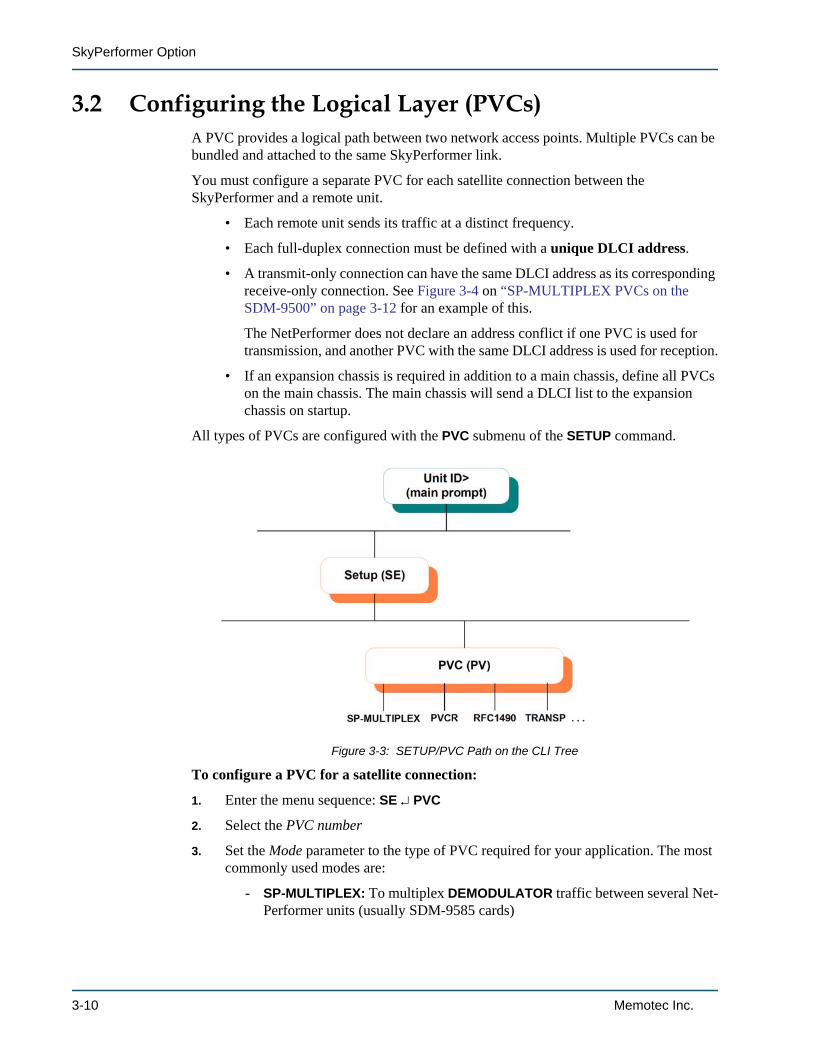
All types of PVCs are configured with the PVC submenu of the SETUP command.
To configure a PVC for a satellite connection:
1. Enter the menu sequence: SE PVC
2. Select the PVC number
3. Set the Mode parameter to the type of PVC required for your application. The most commonly used modes are:
- SP-MULTIPLEX: To multiplex DEMODULATOR traffic between several Net-Performer units (usually SDM-9585 cards)
Figure 3-3: SETUP/PVC Path on the CLI Tree
3-10 Memotec Inc.
Configuration
- PVCR: To access a remote NetPerformer via satellite using PowerCell
- RFC1490: To access a remote RFC1490-compatible FRAD via satellite
- MULTIPLEX: To multiplex data coming from a Frame Relay or X.25 end-user device via satellite
- BROADCAST: To send broadcast analog voice traffic frames to the multicast server (the Frame Relay switch) via satellite
- TRANSPARENT: To switch data coming from one end-user device directly to the satellite network and the destination end-user device without alteration on the frame.
4. Select a unique DLCI address for this PVC
5. Change the other PVC parameters from their default values, if desired.
SP-MULTIPLEX PVC configuration is dealt with in the next section. Special considerations for PVCR PVC configuration are mentioned on “PVCR PVC” on page 3-14. For information concerning the other PVC types, refer to the WAN/Frame Relay fascicle of this document series.
Memotec Inc. 3-11
SkyPerformer Option
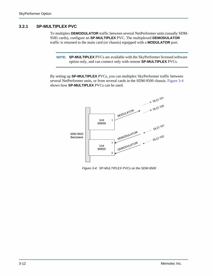
3.2.1 SP-MULTIPLEX PVCTo multiplex DEMODULATOR traffic between several NetPerformer units (usually SDM-9585 cards), configure an SP-MULTIPLEX PVC. The multiplexed DEMODULATOR traffic is returned to the main card (or chassis) equipped with a MODULATOR port.
NOTE: SP-MULTIPLEX PVCs are available with the SkyPerformer licensed software option only, and can connect only with remote SP-MULTIPLEX PVCs.
By setting up SP-MULTIPLEX PVCs, you can multiplex SkyPerformer traffic between several NetPerformer units, or from several cards in the SDM-9500 chassis. Figure 3-4 shows how SP-MULTIPLEX PVCs can be used.
Figure 3-4: SP-MULTIPLEX PVCs on the SDM-9500
3-12 Memotec Inc.
Configuration
SE/PVC/SP-MULTIPLEX example
SDM-9230>SESETUPItem (BRIDGE/CALLER ID/CLASS/CUSTOM/FILTER/GLOBAL/HUNT/IP/IPX/MAP/PHONE/PORT/PU/PVC/SCHEDULE/SLOT/USER/VLAN,def:PORT) ? PVCPVC number (1-300,def:1) ? 2PVC 2> Mode (def:PVCR) ? SP-MULTIPLEXPVC 2> Port (def:1) ?PVC 2> DLCI address (0-1022,def:0) ? 101PVC 2> Committed Information rate (4000-6144000,def:56000) ?PVC 2> Burst Information rate (4000-6144000,def:56000) ?PVC 2> Remote unit name (def:) ? CHICAGO-9230PVC 2> Remote PVC number (1-300,def:1) ?PVC 2> Class number (def:3) ? PVC 2> Compression (def:YES) ?
• Mode is set to SP-MULTIPLEX for this application.
• The Port parameter must refer to an SP port set in MODULATOR or DEMODU-LATOR mode.
• The Class number can be set to 1, 2, 3, 4, 5, 6, 7, 8 or HIGH PRIORITY.
Use the SETUP/CLASS submenu to define the relative weight and preferred route for each numeric priority class. For details, refer to the Quality of Service (QoS) fascicle of this document series.
• The other parameters behave as for a PVCR PVC, described in the next section.
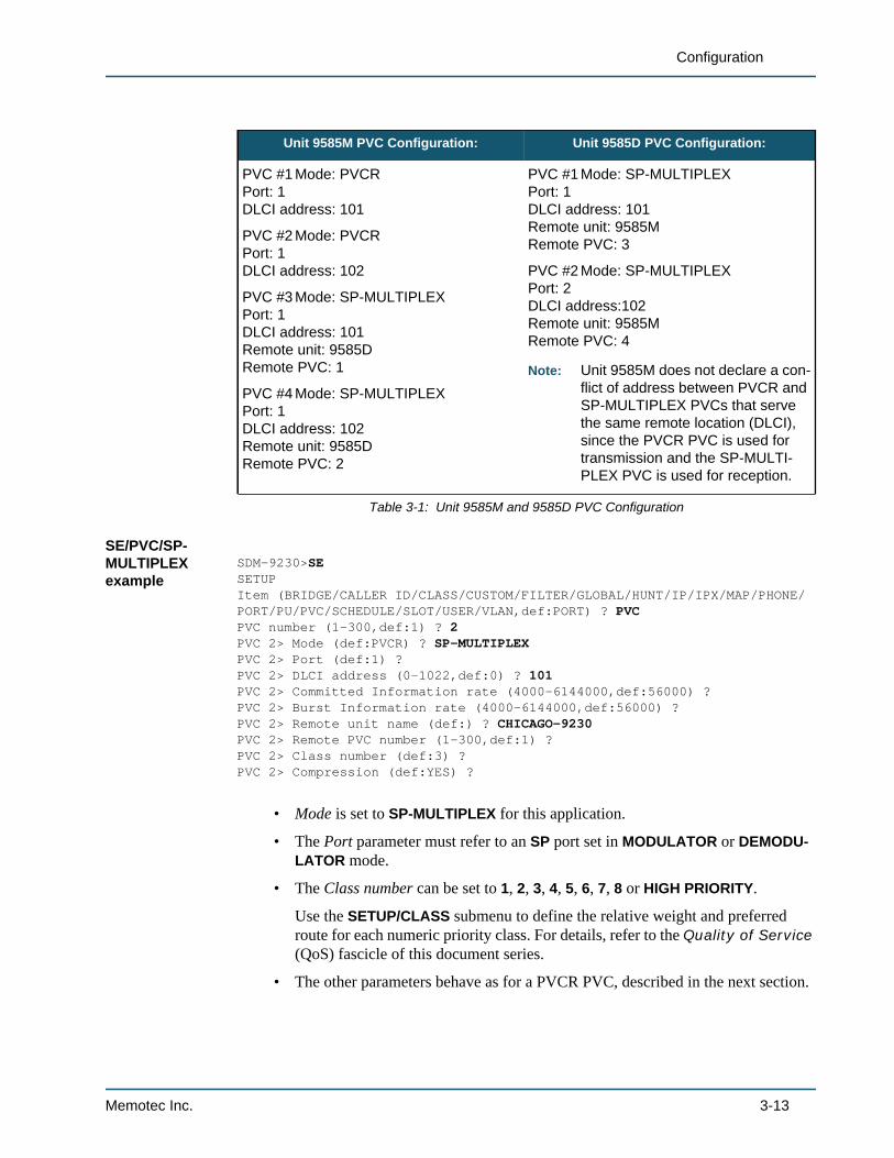
Unit 9585M PVC Configuration: Unit 9585D PVC Configuration:
PVC #1 Mode: PVCRPort: 1DLCI address: 101
PVC #2 Mode: PVCRPort: 1DLCI address: 102
PVC #3 Mode: SP-MULTIPLEXPort: 1DLCI address: 101Remote unit: 9585DRemote PVC: 1
PVC #4 Mode: SP-MULTIPLEXPort: 1DLCI address: 102Remote unit: 9585DRemote PVC: 2
PVC #1 Mode: SP-MULTIPLEXPort: 1DLCI address: 101Remote unit: 9585MRemote PVC: 3
PVC #2 Mode: SP-MULTIPLEXPort: 2DLCI address:102Remote unit: 9585MRemote PVC: 4
Note: Unit 9585M does not declare a con-flict of address between PVCR and SP-MULTIPLEX PVCs that serve the same remote location (DLCI), since the PVCR PVC is used for transmission and the SP-MULTI-PLEX PVC is used for reception.
Table 3-1: Unit 9585M and 9585D PVC Configuration
Memotec Inc. 3-13
SkyPerformer Option
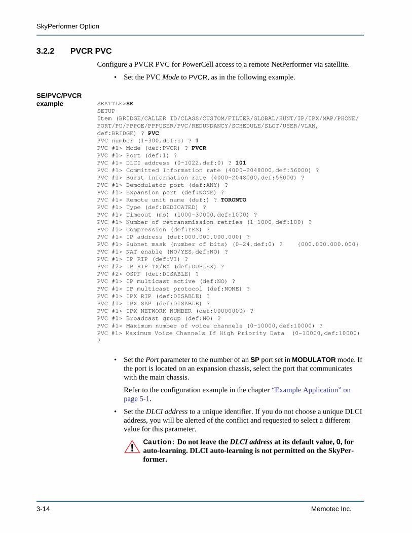
3.2.2 PVCR PVCConfigure a PVCR PVC for PowerCell access to a remote NetPerformer via satellite.
• Set the PVC Mode to PVCR, as in the following example.
SE/PVC/PVCR example SEATTLE>SE
SETUPItem (BRIDGE/CALLER ID/CLASS/CUSTOM/FILTER/GLOBAL/HUNT/IP/IPX/MAP/PHONE/PORT/PU/PPPOE/PPPUSER/PVC/REDUNDANCY/SCHEDULE/SLOT/USER/VLAN,def:BRIDGE) ? PVCPVC number (1-300,def:1) ? 1PVC #1> Mode (def:PVCR) ? PVCRPVC #1> Port (def:1) ? PVC #1> DLCI address (0-1022,def:0) ? 101PVC #1> Committed Information rate (4000-2048000,def:56000) ? PVC #1> Burst Information rate (4000-2048000,def:56000) ? PVC #1> Demodulator port (def:ANY) ? PVC #1> Expansion port (def:NONE) ? PVC #1> Remote unit name (def:) ? TORONTOPVC #1> Type (def:DEDICATED) ? PVC #1> Timeout (ms) (1000-30000,def:1000) ? PVC #1> Number of retransmission retries (1-1000,def:100) ? PVC #1> Compression (def:YES) ? PVC #1> IP address (def:000.000.000.000) ? PVC #1> Subnet mask (number of bits) (0-24,def:0) ? {000.000.000.000}PVC #1> NAT enable (NO/YES,def:NO) ? PVC #1> IP RIP (def:V1) ? PVC #2> IP RIP TX/RX (def:DUPLEX) ? PVC #2> OSPF (def:DISABLE) ? PVC #1> IP multicast active (def:NO) ? PVC #1> IP multicast protocol (def:NONE) ? PVC #1> IPX RIP (def:DISABLE) ? PVC #1> IPX SAP (def:DISABLE) ? PVC #1> IPX NETWORK NUMBER (def:00000000) ? PVC #1> Broadcast group (def:NO) ? PVC #1> Maximum number of voice channels (0-10000,def:10000) ? PVC #1> Maximum Voice Channels If High Priority Data (0-10000,def:10000) ?
• Set the Port parameter to the number of an SP port set in MODULATOR mode. If the port is located on an expansion chassis, select the port that communicates with the main chassis.
Refer to the configuration example in the chapter “Example Application” on page 5-1.
• Set the DLCI address to a unique identifier. If you do not choose a unique DLCI address, you will be alerted of the conflict and requested to select a different value for this parameter.
Caution: Do not leave the DLCI address at its default value, 0, for auto-learning. DLCI auto-learning is not permitted on the SkyPer-former.
3-14 Memotec Inc.
Configuration
• The Type can be set to DEDICATED, ANSWER or CALL-BKUP. These choices are configured in much the same way as for a backup WAN link. For details, refer to the WAN/Frame Relay fascicle of this document series.
On a CALL-BKUP PVC, the Backup parameter can be set to ANY or ALL.
• If you leave the IP address at its default value, 0.0.0.0, the PVC will operate in unnumbered IP mode.
• IP RIP can be set to DISABLE, V1, V2 BROADCAST or V2 MULTICAST.
• All parameters affecting IP RIP, NAT, OSPF, IP Multicast and IPX are similar to those used for configuring a WAN link. For details, refer to the WAN/Frame Relay fascicle of this document series.
• Set Broadcast group to YES to assign this PVC to a broadcast group.
Memotec Inc. 3-15

SkyPerformer Option
3-16 Memotec Inc.

4
Monitoring and StatisticsMemotec Inc. 4-1
SkyPerformer Option
4.1 About the Statistics CommandsOnce the unit is powered up and the data ports are activated, you can execute NetPerformer statistics commands from the console to check the status of SkyPerformer operations.
NOTE: All of the commands mentioned in this chapter can be executed by users with FULL or MONITOR console access.
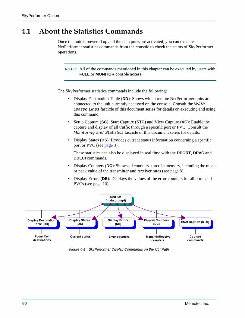
The SkyPerformer statistics commands include the following:
• Display Destination Table (DD): Shows which remote NetPerformer units are connected to the unit currently accessed on the console. Consult the WAN/Leased Lines fascicle of this document series for details on executing and using this command.
• Setup Capture (SC), Start Capture (STC) and View Capture (VC): Enable the capture and display of all traffic through a specific port or PVC. Consult the Monitoring and Statistics fascicle of this document series for details.
• Display States (DS): Provides current status information concerning a specific port or PVC (see page 3).
These statistics can also be displayed in real time with the DPORT, DPVC and DDLCI commands.
• Display Counters (DC): Shows all counters stored in memory, including the mean or peak value of the transmitter and receiver rates (see page 8).
• Display Errors (DE): Displays the values of the error counters for all ports and PVCs (see page 10).
Figure 4-1: SkyPerformer Display Commands on the CLI Path
4-2 Memotec Inc.
Monitoring and Statistics
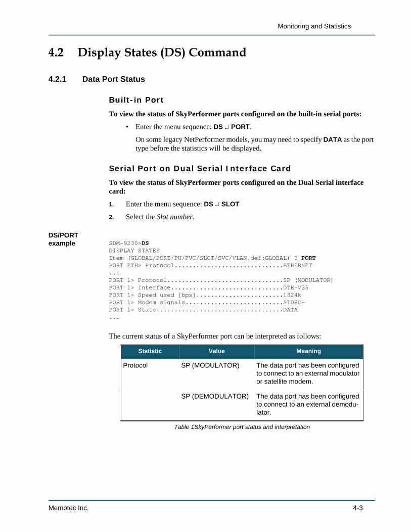
4.2 Display States (DS) Command
4.2.1 Data Port Status
Built-in Port
To view the status of SkyPerformer ports configured on the built-in serial ports:
• Enter the menu sequence: DS PORT.
On some legacy NetPerformer models, you may need to specify DATA as the port type before the statistics will be displayed.
Serial Port on Dual Serial Interface Card
To view the status of SkyPerformer ports configured on the Dual Serial interface card:
1. Enter the menu sequence: DS SLOT
2. Select the Slot number.
DS/PORT example SDM-9230>DS
DISPLAY STATESItem (GLOBAL/PORT/PU/PVC/SLOT/SVC/VLAN,def:GLOBAL) ? PORTPORT ETH> Protocol..............................ETHERNET...PORT 1> Protocol................................SP (MODULATOR)PORT 1> Interface...............................DTE-V35PORT 1> Speed used [bps]........................1824kPORT 1> Modem signals...........................STDRC-PORT 1> State...................................DATA...
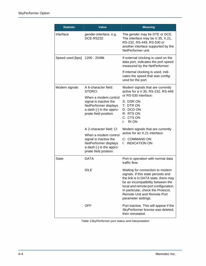
The current status of a SkyPerformer port can be interpreted as follows:
Statistic Value Meaning
Protocol SP (MODULATOR) The data port has been configured to connect to an external modulator or satellite modem.
SP (DEMODULATOR) The data port has been configured to connect to an external demodu-lator.
Table 1SkyPerformer port status and interpretation
Memotec Inc. 4-3
SkyPerformer Option
Interface gender-interface, e.g. DCE-RS232
The gender may be DTE or DCE. The interface may be V.35, X.21, RS-232, RS-449, RS-530 or another interface supported by the NetPerformer unit.
Speed used [bps] 1200 - 2048k If external clocking is used on the data port, indicates the port speed measured by the NetPerformer.
If internal clocking is used, indi-cates the speed that was config-ured for the port.
Modem signals A 6-character field: STDRCI
When a modem control signal is inactive the NetPerformer displays a dash [-] in the appro-priate field position.
Modem signals that are currently active for a V.35, RS-232, RS-449 or RS-530 interface:
S: DSR ONT: DTR OND: DCD ONR: RTS ONC: CTS ONI: RI ON
A 2-character field: CI
When a modem control signal is inactive the NetPerformer displays a dash [-] in the appro-priate field position.
Modem signals that are currently active for an X.21 interface:
C: COMMAND ONI: INDICATION ON
State DATA Port in operation with normal data traffic flow.
IDLE Waiting for connection to modem signals. If this state persists and the link is in DATA state, there may be an incompatibility between the local and remote port configuration. In particular, check the Protocol, Remote Unit and Remote Port parameter settings.
OFF Port inactive. This will appear if the SkyPerformer license was deleted, then reinstated.
Statistic Value Meaning
Table 1SkyPerformer port status and interpretation
4-4 Memotec Inc.
Monitoring and Statistics
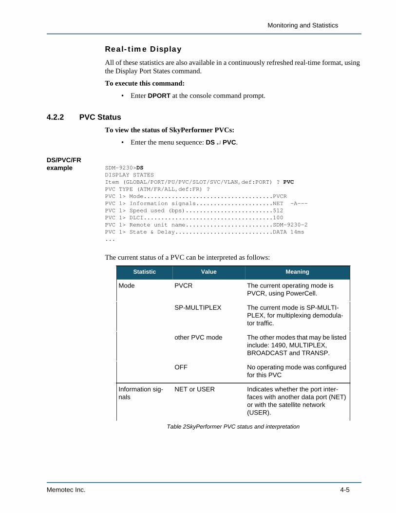
Real-time Display
All of these statistics are also available in a continuously refreshed real-time format, using the Display Port States command.
To execute this command:
• Enter DPORT at the console command prompt.
4.2.2 PVC StatusTo view the status of SkyPerformer PVCs:
• Enter the menu sequence: DS PVC.
DS/PVC/FR example SDM-9230>DS
DISPLAY STATESItem (GLOBAL/PORT/PU/PVC/SLOT/SVC/VLAN,def:PORT) ? PVCPVC TYPE (ATM/FR/ALL,def:FR) ?PVC 1> Mode.....................................PVCRPVC 1> Information signals......................NET -A---PVC 1> Speed used (bps).........................512PVC 1> DLCI.....................................100PVC 1> Remote unit name.........................SDM-9230-2PVC 1> State & Delay............................DATA 14ms...
The current status of a PVC can be interpreted as follows:
Statistic Value Meaning
Mode PVCR The current operating mode is PVCR, using PowerCell.
SP-MULTIPLEX The current mode is SP-MULTI-PLEX, for multiplexing demodula-tor traffic.
other PVC mode The other modes that may be listed include: 1490, MULTIPLEX, BROADCAST and TRANSP.
OFF No operating mode was configured for this PVC
Information sig-nals
NET or USER Indicates whether the port inter-faces with another data port (NET) or with the satellite network (USER).
Table 2SkyPerformer PVC status and interpretation
Memotec Inc. 4-5
SkyPerformer Option
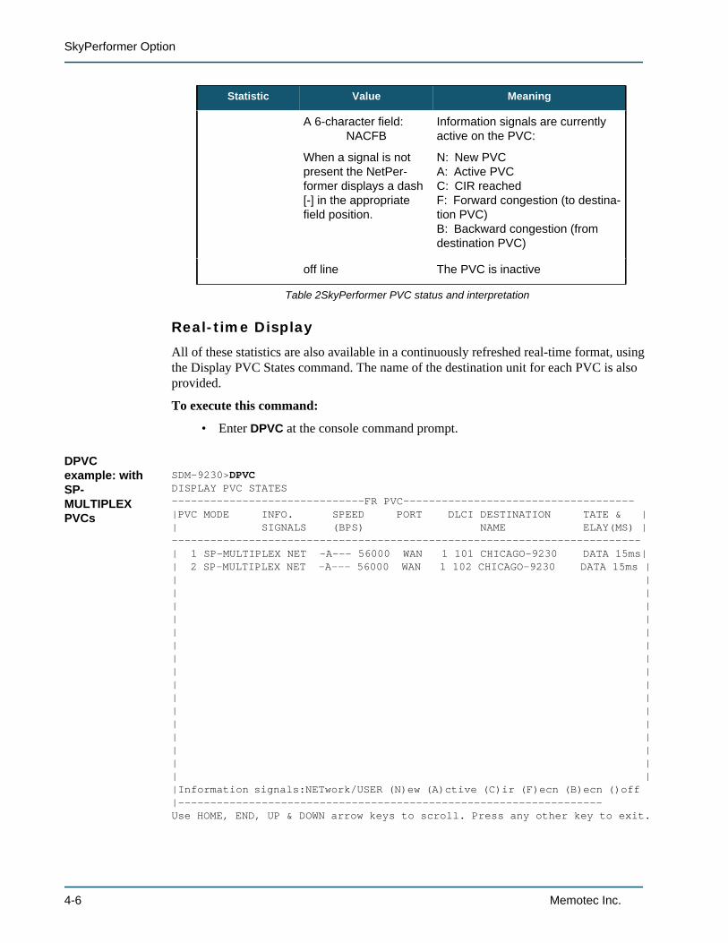
Real-time Display
All of these statistics are also available in a continuously refreshed real-time format, using the Display PVC States command. The name of the destination unit for each PVC is also provided.
To execute this command:
• Enter DPVC at the console command prompt.
DPVC example: with SP-MULTIPLEX PVCs
SDM-9230>DPVCDISPLAY PVC STATES------------------------------FR PVC------------------------------------|PVC MODE INFO. SPEED PORT DLCI DESTINATION TATE & || SIGNALS (BPS) NAME ELAY(MS) |-------------------------------------------------------------------------| 1 SP-MULTIPLEX NET -A--- 56000 WAN 1 101 CHICAGO-9230 DATA 15ms|| 2 SP-MULTIPLEX NET -A--- 56000 WAN 1 102 CHICAGO-9230 DATA 15ms || || || || || || || || || || || || || || || || ||Information signals:NETwork/USER (N)ew (A)ctive (C)ir (F)ecn (B)ecn ()off |------------------------------------------------------------------Use HOME, END, UP & DOWN arrow keys to scroll. Press any other key to exit.
A 6-character field:NACFB
When a signal is not present the NetPer-former displays a dash [-] in the appropriate field position.
Information signals are currently active on the PVC:
N: New PVCA: Active PVCC: CIR reachedF: Forward congestion (to destina-tion PVC)B: Backward congestion (from destination PVC)
off line The PVC is inactive
Statistic Value Meaning
Table 2SkyPerformer PVC status and interpretation
4-6 Memotec Inc.
Monitoring and Statistics
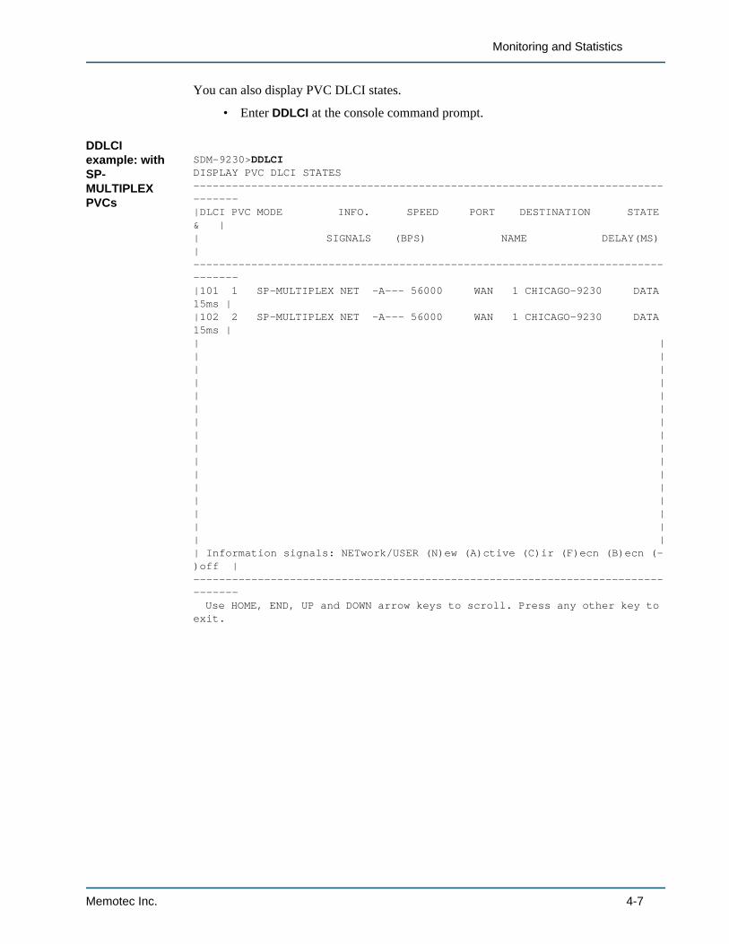
You can also display PVC DLCI states.
• Enter DDLCI at the console command prompt.
DDLCI example: with SP-MULTIPLEX PVCs
SDM-9230>DDLCIDISPLAY PVC DLCI STATES--------------------------------------------------------------------------------|DLCI PVC MODE INFO. SPEED PORT DESTINATION STATE & || SIGNALS (BPS) NAME DELAY(MS) |--------------------------------------------------------------------------------|101 1 SP-MULTIPLEX NET -A--- 56000 WAN 1 CHICAGO-9230 DATA 15ms ||102 2 SP-MULTIPLEX NET -A--- 56000 WAN 1 CHICAGO-9230 DATA 15ms || || || || || || || || || || || || || || || || || Information signals: NETwork/USER (N)ew (A)ctive (C)ir (F)ecn (B)ecn (-)off |-------------------------------------------------------------------------------- Use HOME, END, UP and DOWN arrow keys to scroll. Press any other key to exit.
Memotec Inc. 4-7
SkyPerformer Option
4.3 Display Counters (DC) Command
4.3.1 Data Port Counters
Built-in Port
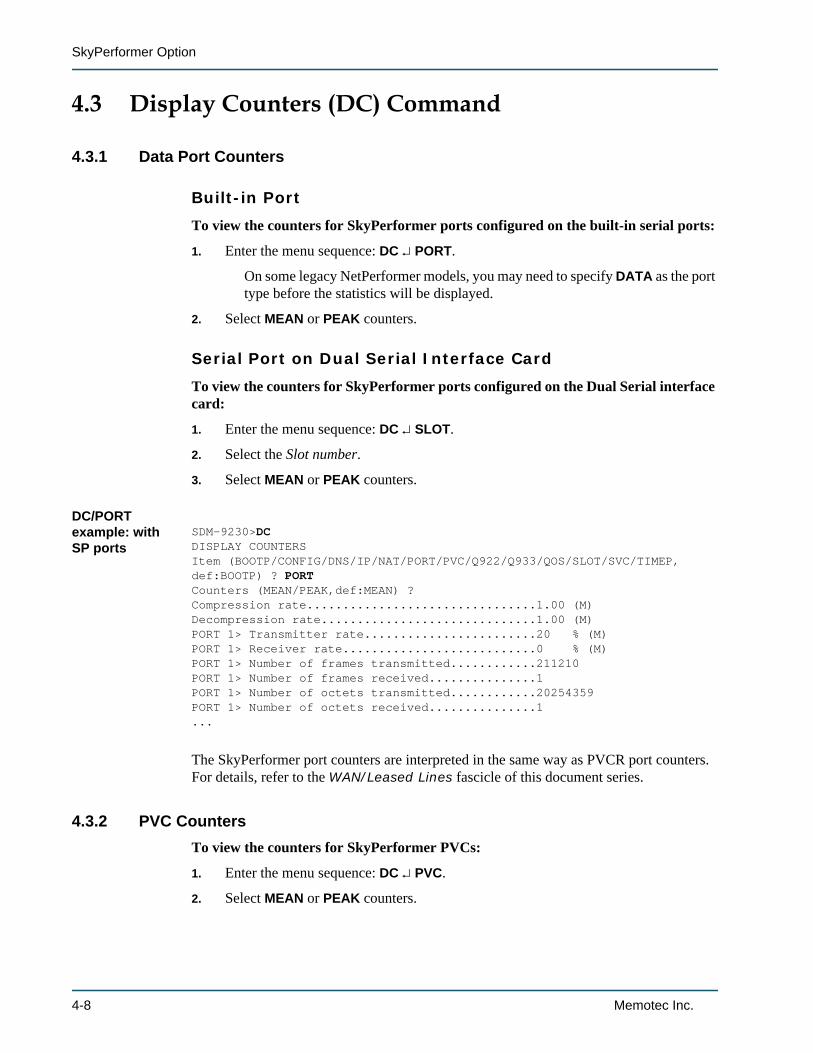
To view the counters for SkyPerformer ports configured on the built-in serial ports:
1. Enter the menu sequence: DC PORT.
On some legacy NetPerformer models, you may need to specify DATA as the port type before the statistics will be displayed.
2. Select MEAN or PEAK counters.
Serial Port on Dual Serial Interface Card
To view the counters for SkyPerformer ports configured on the Dual Serial interface card:
1. Enter the menu sequence: DC SLOT.
2. Select the Slot number.
3. Select MEAN or PEAK counters.
DC/PORT example: with SP ports
SDM-9230>DCDISPLAY COUNTERSItem (BOOTP/CONFIG/DNS/IP/NAT/PORT/PVC/Q922/Q933/QOS/SLOT/SVC/TIMEP,def:BOOTP) ? PORTCounters (MEAN/PEAK,def:MEAN) ?Compression rate................................1.00 (M)Decompression rate..............................1.00 (M)PORT 1> Transmitter rate........................20 % (M)PORT 1> Receiver rate...........................0 % (M)PORT 1> Number of frames transmitted............211210PORT 1> Number of frames received...............1PORT 1> Number of octets transmitted............20254359PORT 1> Number of octets received...............1...
The SkyPerformer port counters are interpreted in the same way as PVCR port counters. For details, refer to the WAN/Leased Lines fascicle of this document series.
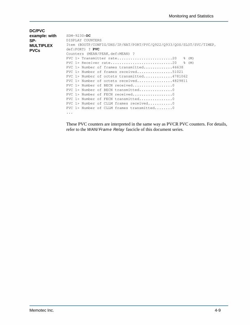
4.3.2 PVC CountersTo view the counters for SkyPerformer PVCs:
1. Enter the menu sequence: DC PVC.
2. Select MEAN or PEAK counters.
4-8 Memotec Inc.
Monitoring and Statistics
DC/PVC example: with SP-MULTIPLEX PVCs
SDM-9230>DCDISPLAY COUNTERSItem (BOOTP/CONFIG/DNS/IP/NAT/PORT/PVC/Q922/Q933/QOS/SLOT/SVC/TIMEP,def:PORT) ? PVCCounters (MEAN/PEAK,def:MEAN) ?PVC 1> Transmitter rate.........................20 % (M)PVC 1> Receiver rate............................20 % (M)PVC 1> Number of frames transmitted.............46638PVC 1> Number of frames received................51021PVC 1> Number of octets transmitted.............4781062PVC 1> Number of octets received................4829811PVC 1> Number of BECN received..................0PVC 1> Number of BECN transmitted...............0PVC 1> Number of FECN received..................0PVC 1> Number of FECN transmitted...............0PVC 1> Number of CLLM frames received...........0PVC 1> Number of CLLM frames transmitted........0...
These PVC counters are interpreted in the same way as PVCR PVC counters. For details, refer to the WAN/Frame Relay fascicle of this document series.
Memotec Inc. 4-9
SkyPerformer Option
4.4 Display Errors (DE) Command
4.4.1 Data Port Errors
Built-in Port
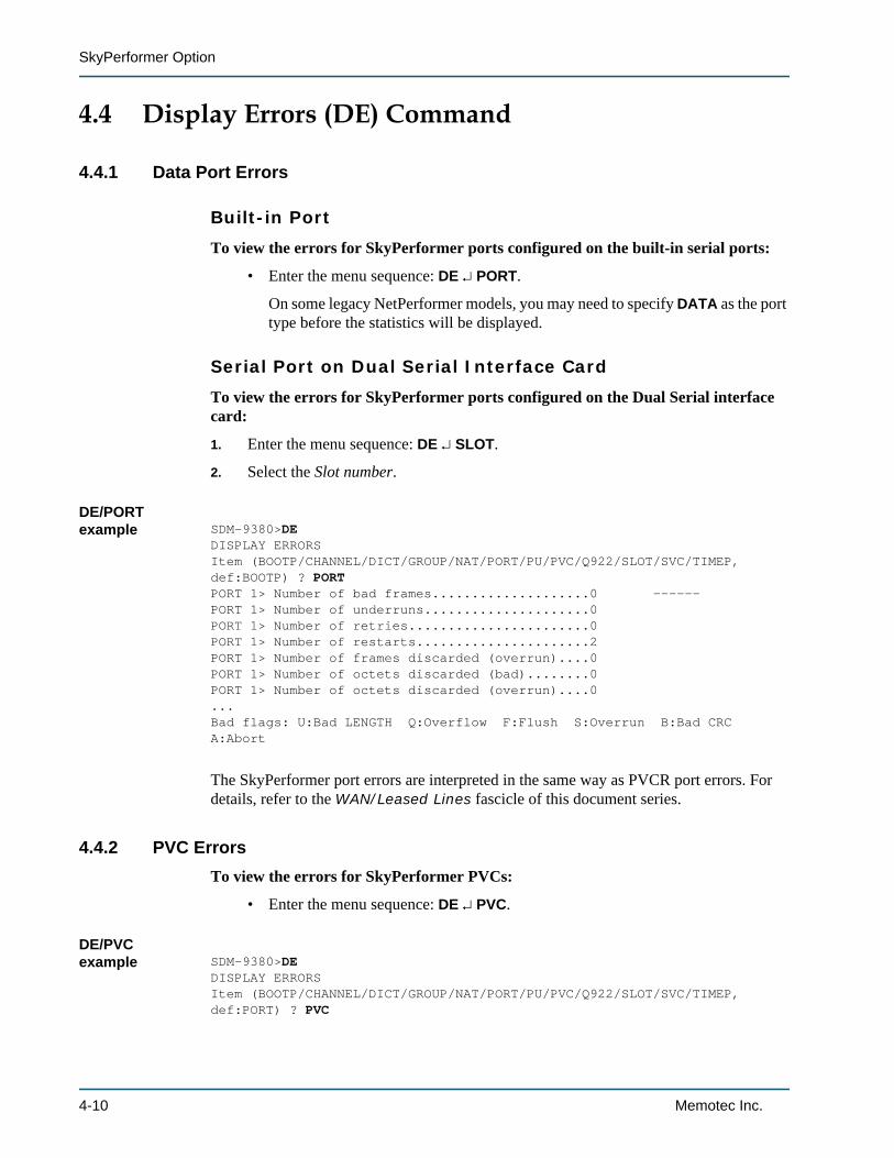
To view the errors for SkyPerformer ports configured on the built-in serial ports:
• Enter the menu sequence: DE PORT.
On some legacy NetPerformer models, you may need to specify DATA as the port type before the statistics will be displayed.
Serial Port on Dual Serial Interface Card
To view the errors for SkyPerformer ports configured on the Dual Serial interface card:
1. Enter the menu sequence: DE SLOT.
2. Select the Slot number.
DE/PORT example SDM-9380>DE
DISPLAY ERRORSItem (BOOTP/CHANNEL/DICT/GROUP/NAT/PORT/PU/PVC/Q922/SLOT/SVC/TIMEP,def:BOOTP) ? PORTPORT 1> Number of bad frames....................0 ------PORT 1> Number of underruns.....................0PORT 1> Number of retries.......................0PORT 1> Number of restarts......................2PORT 1> Number of frames discarded (overrun)....0PORT 1> Number of octets discarded (bad)........0PORT 1> Number of octets discarded (overrun)....0...Bad flags: U:Bad LENGTH Q:Overflow F:Flush S:Overrun B:Bad CRC A:Abort
The SkyPerformer port errors are interpreted in the same way as PVCR port errors. For details, refer to the WAN/Leased Lines fascicle of this document series.
4.4.2 PVC ErrorsTo view the errors for SkyPerformer PVCs:
• Enter the menu sequence: DE PVC.
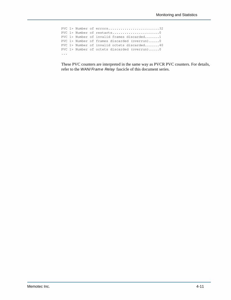
DE/PVC example SDM-9380>DE
DISPLAY ERRORSItem (BOOTP/CHANNEL/DICT/GROUP/NAT/PORT/PU/PVC/Q922/SLOT/SVC/TIMEP,def:PORT) ? PVC
4-10 Memotec Inc.
Monitoring and Statistics
PVC 1> Number of errors.........................32PVC 1> Number of restarts.......................0PVC 1> Number of invalid frames discarded.......1PVC 1> Number of frames discarded (overrun).....0PVC 1> Number of invalid octets discarded.......40PVC 1> Number of octets discarded (overrun).....0...
These PVC counters are interpreted in the same way as PVCR PVC counters. For details, refer to the WAN/Frame Relay fascicle of this document series.
Memotec Inc. 4-11

SkyPerformer Option
4-12 Memotec Inc.
5
Example ApplicationMemotec Inc. 5-1
SkyPerformer Option
5.1 About this ChapterThis chapter provides an example of the SkyPerformer in a simple satellite network application.
• Only the essential parameters required to configure the SkyPerformer are shown. All other parameters may be left at their default values.
• Critical parameter values are given in boldface, for example:
PVC 1> Mode.......................................PVCR
To ensure trouble-free operations, these critical parameters must be configured correctly for your application.
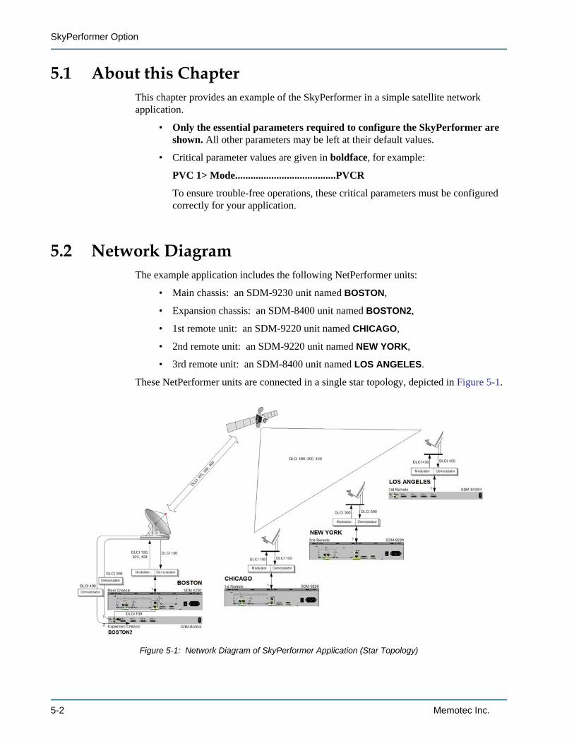
5.2 Network DiagramThe example application includes the following NetPerformer units:
• Main chassis: an SDM-9230 unit named BOSTON,
• Expansion chassis: an SDM-8400 unit named BOSTON2,
• 1st remote unit: an SDM-9220 unit named CHICAGO,
• 2nd remote unit: an SDM-9220 unit named NEW YORK,
• 3rd remote unit: an SDM-8400 unit named LOS ANGELES.
These NetPerformer units are connected in a single star topology, depicted in Figure 5-1.
Figure 5-1: Network Diagram of SkyPerformer Application (Star Topology)
5-2 Memotec Inc.
Example Application
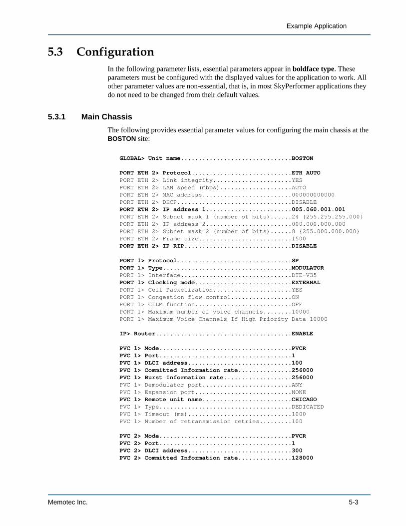
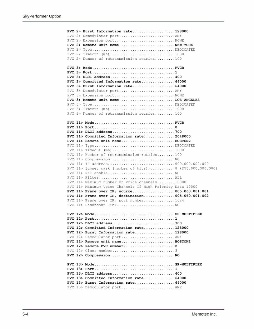
5.3 ConfigurationIn the following parameter lists, essential parameters appear in boldface type. These parameters must be configured with the displayed values for the application to work. All other parameter values are non-essential, that is, in most SkyPerformer applications they do not need to be changed from their default values.
5.3.1 Main ChassisThe following provides essential parameter values for configuring the main chassis at the BOSTON site:
GLOBAL> Unit name...............................BOSTON
PORT ETH 2> Protocol............................ETH AUTOPORT ETH 2> Link integrity......................YESPORT ETH 2> LAN speed (mbps)....................AUTOPORT ETH 2> MAC address.........................000000000000PORT ETH 2> DHCP................................DISABLEPORT ETH 2> IP address 1........................005.060.001.001PORT ETH 2> Subnet mask 1 (number of bits)......24 {255.255.255.000}PORT ETH 2> IP address 2........................000.000.000.000PORT ETH 2> Subnet mask 2 (number of bits)......8 {255.000.000.000}PORT ETH 2> Frame size..........................1500PORT ETH 2> IP RIP..............................DISABLE
PORT 1> Protocol................................SPPORT 1> Type....................................MODULATORPORT 1> Interface...............................DTE-V35PORT 1> Clocking mode...........................EXTERNALPORT 1> Cell Packetization......................YESPORT 1> Congestion flow control.................ONPORT 1> CLLM function...........................OFFPORT 1> Maximum number of voice channels........10000PORT 1> Maximum Voice Channels If High Priority Data 10000
IP> Router......................................ENABLE
PVC 1> Mode.....................................PVCRPVC 1> Port.....................................1PVC 1> DLCI address.............................100PVC 1> Committed Information rate...............256000PVC 1> Burst Information rate...................256000PVC 1> Demodulator port.........................ANYPVC 1> Expansion port...........................NONEPVC 1> Remote unit name.........................CHICAGOPVC 1> Type.....................................DEDICATEDPVC 1> Timeout (ms).............................1000PVC 1> Number of retransmission retries.........100
PVC 2> Mode.....................................PVCRPVC 2> Port.....................................1PVC 2> DLCI address.............................300PVC 2> Committed Information rate...............128000
Memotec Inc. 5-3
SkyPerformer Option
PVC 2> Burst Information rate...................128000PVC 2> Demodulator port.........................ANYPVC 2> Expansion port...........................NONEPVC 2> Remote unit name.........................NEW YORKPVC 2> Type.....................................DEDICATEDPVC 2> Timeout (ms).............................1000PVC 2> Number of retransmission retries.........100
PVC 3> Mode.....................................PVCRPVC 3> Port.....................................1PVC 3> DLCI address.............................400PVC 3> Committed Information rate...............64000PVC 3> Burst Information rate...................64000PVC 3> Demodulator port.........................ANYPVC 3> Expansion port...........................NONEPVC 3> Remote unit name.........................LOS ANGELESPVC 3> Type.....................................DEDICATEDPVC 3> Timeout (ms).............................1000PVC 3> Number of retransmission retries.........100
PVC 11> Mode....................................PVCRPVC 11> Port....................................0PVC 11> DLCI address............................700PVC 11> Committed Information rate..............2048000PVC 11> Remote unit name........................BOSTON2PVC 11> Type....................................DEDICATEDPVC 11> Timeout (ms)............................1000PVC 11> Number of retransmission retries........100PVC 11> Compression.............................NOPVC 11> IP address..............................000.000.000.000PVC 11> Subnet mask (number of bits)............8 {255.000.000.000}PVC 11> NAT enable..............................NOPVC 11> Filter..................................ALLPVC 11> Maximum number of voice channels........10000PVC 11> Maximum Voice Channels If High Priority Data 10000PVC 11> Frame over IP, source...................005.060.001.001PVC 11> Frame over IP, destination..............005.060.001.002PVC 11> Frame over IP, port number..............1024PVC 11> Redundant link..........................NO
PVC 12> Mode....................................SP-MULTIPLEXPVC 12> Port....................................1PVC 12> DLCI address............................300PVC 12> Committed Information rate..............128000PVC 12> Burst Information rate..................128000PVC 12> Demodulator port........................ANYPVC 12> Remote unit name........................BOSTON2PVC 12> Remote PVC number.......................2PVC 12> Class number............................3PVC 12> Compression.............................NO
PVC 13> Mode....................................SP-MULTIPLEXPVC 13> Port....................................1PVC 13> DLCI address............................400PVC 13> Committed Information rate..............64000PVC 13> Burst Information rate..................64000PVC 13> Demodulator port........................ANY
5-4 Memotec Inc.
Example Application
PVC 13> Remote unit name........................BOSTON2PVC 13> Remote PVC number.......................3PVC 13> Class number............................3PVC 13> Compression.............................NO
EXTENDED PARAMETERSIP> (MULTIHOMEDTYPE) Multihomed type............DISABLED
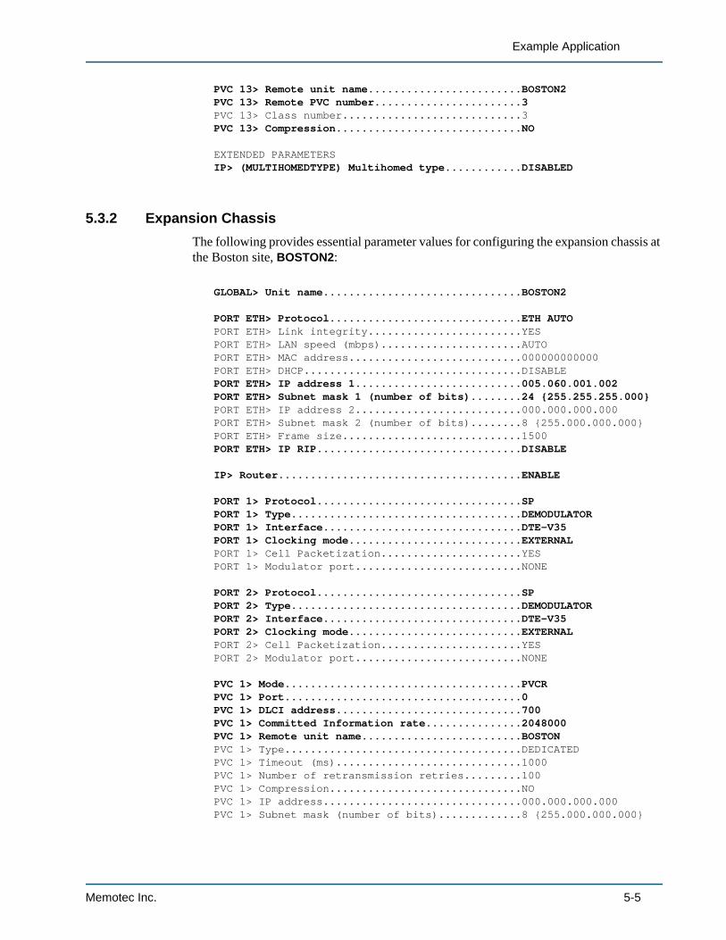
5.3.2 Expansion ChassisThe following provides essential parameter values for configuring the expansion chassis at the Boston site, BOSTON2:
GLOBAL> Unit name...............................BOSTON2
PORT ETH> Protocol..............................ETH AUTOPORT ETH> Link integrity........................YESPORT ETH> LAN speed (mbps)......................AUTOPORT ETH> MAC address...........................000000000000PORT ETH> DHCP..................................DISABLEPORT ETH> IP address 1..........................005.060.001.002PORT ETH> Subnet mask 1 (number of bits)........24 {255.255.255.000}PORT ETH> IP address 2..........................000.000.000.000PORT ETH> Subnet mask 2 (number of bits)........8 {255.000.000.000}PORT ETH> Frame size............................1500PORT ETH> IP RIP................................DISABLE
IP> Router......................................ENABLE
PORT 1> Protocol................................SPPORT 1> Type....................................DEMODULATORPORT 1> Interface...............................DTE-V35PORT 1> Clocking mode...........................EXTERNALPORT 1> Cell Packetization......................YESPORT 1> Modulator port..........................NONE
PORT 2> Protocol................................SPPORT 2> Type....................................DEMODULATORPORT 2> Interface...............................DTE-V35PORT 2> Clocking mode...........................EXTERNALPORT 2> Cell Packetization......................YESPORT 2> Modulator port..........................NONE
PVC 1> Mode.....................................PVCRPVC 1> Port.....................................0PVC 1> DLCI address.............................700PVC 1> Committed Information rate...............2048000PVC 1> Remote unit name.........................BOSTONPVC 1> Type.....................................DEDICATEDPVC 1> Timeout (ms).............................1000PVC 1> Number of retransmission retries.........100PVC 1> Compression..............................NOPVC 1> IP address...............................000.000.000.000PVC 1> Subnet mask (number of bits).............8 {255.000.000.000}
Memotec Inc. 5-5
SkyPerformer Option
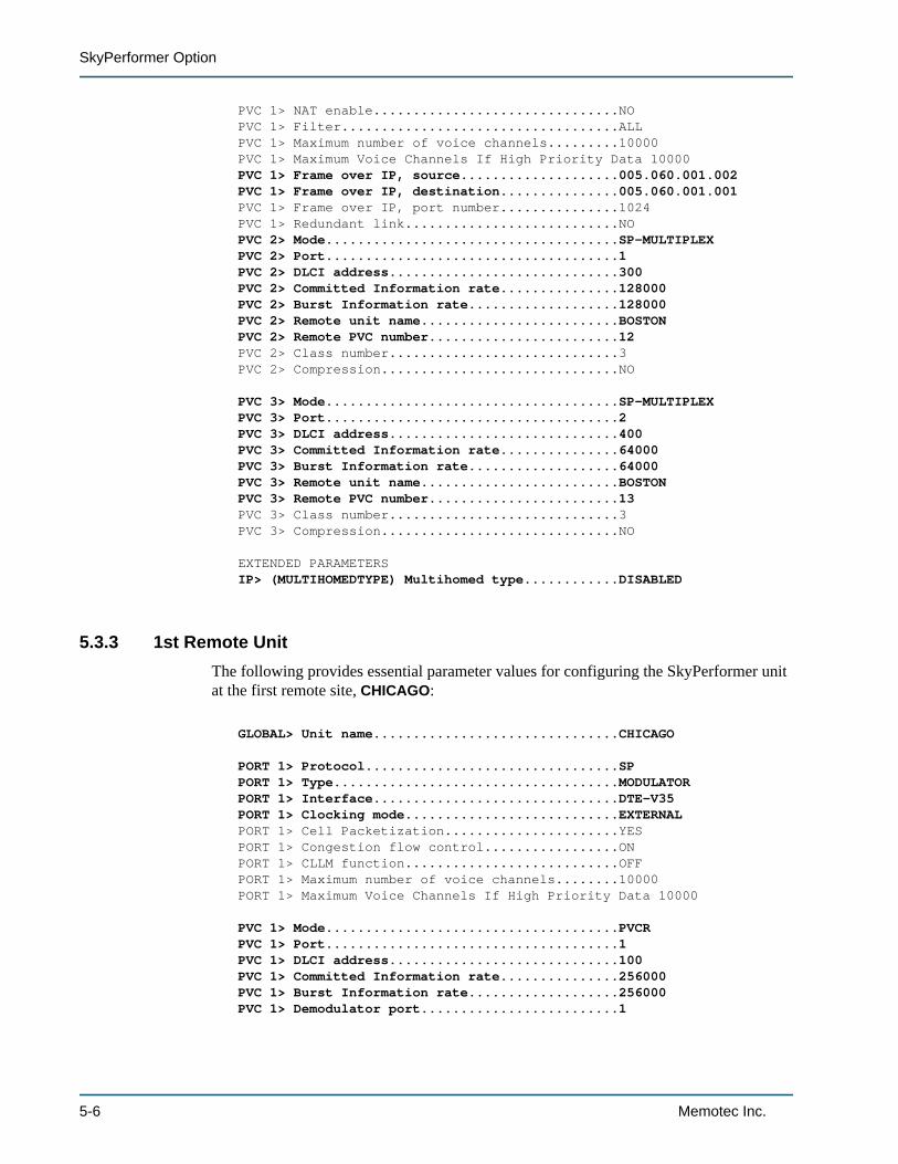
PVC 1> NAT enable...............................NOPVC 1> Filter...................................ALLPVC 1> Maximum number of voice channels.........10000PVC 1> Maximum Voice Channels If High Priority Data 10000PVC 1> Frame over IP, source....................005.060.001.002PVC 1> Frame over IP, destination...............005.060.001.001PVC 1> Frame over IP, port number...............1024PVC 1> Redundant link...........................NOPVC 2> Mode.....................................SP-MULTIPLEXPVC 2> Port.....................................1PVC 2> DLCI address.............................300PVC 2> Committed Information rate...............128000PVC 2> Burst Information rate...................128000PVC 2> Remote unit name.........................BOSTONPVC 2> Remote PVC number........................12PVC 2> Class number.............................3PVC 2> Compression..............................NO
PVC 3> Mode.....................................SP-MULTIPLEXPVC 3> Port.....................................2PVC 3> DLCI address.............................400PVC 3> Committed Information rate...............64000PVC 3> Burst Information rate...................64000PVC 3> Remote unit name.........................BOSTONPVC 3> Remote PVC number........................13PVC 3> Class number.............................3PVC 3> Compression..............................NO
EXTENDED PARAMETERSIP> (MULTIHOMEDTYPE) Multihomed type............DISABLED
5.3.3 1st Remote UnitThe following provides essential parameter values for configuring the SkyPerformer unit at the first remote site, CHICAGO:
GLOBAL> Unit name...............................CHICAGO
PORT 1> Protocol................................SPPORT 1> Type....................................MODULATORPORT 1> Interface...............................DTE-V35PORT 1> Clocking mode...........................EXTERNALPORT 1> Cell Packetization......................YESPORT 1> Congestion flow control.................ONPORT 1> CLLM function...........................OFFPORT 1> Maximum number of voice channels........10000PORT 1> Maximum Voice Channels If High Priority Data 10000
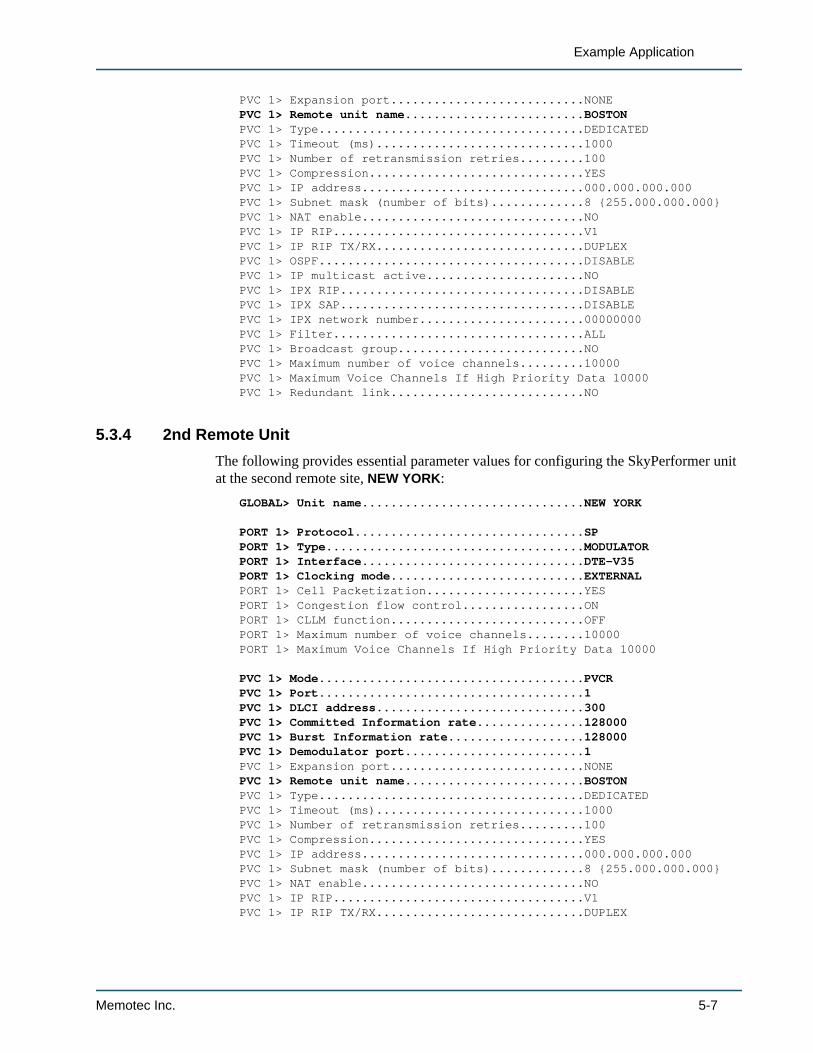
PVC 1> Mode.....................................PVCRPVC 1> Port.....................................1PVC 1> DLCI address.............................100PVC 1> Committed Information rate...............256000PVC 1> Burst Information rate...................256000PVC 1> Demodulator port.........................1
5-6 Memotec Inc.
Example Application
PVC 1> Expansion port...........................NONEPVC 1> Remote unit name.........................BOSTONPVC 1> Type.....................................DEDICATEDPVC 1> Timeout (ms).............................1000PVC 1> Number of retransmission retries.........100PVC 1> Compression..............................YESPVC 1> IP address...............................000.000.000.000PVC 1> Subnet mask (number of bits).............8 {255.000.000.000}PVC 1> NAT enable...............................NOPVC 1> IP RIP...................................V1PVC 1> IP RIP TX/RX.............................DUPLEXPVC 1> OSPF.....................................DISABLEPVC 1> IP multicast active......................NOPVC 1> IPX RIP..................................DISABLEPVC 1> IPX SAP..................................DISABLEPVC 1> IPX network number.......................00000000PVC 1> Filter...................................ALLPVC 1> Broadcast group..........................NOPVC 1> Maximum number of voice channels.........10000PVC 1> Maximum Voice Channels If High Priority Data 10000PVC 1> Redundant link...........................NO
5.3.4 2nd Remote UnitThe following provides essential parameter values for configuring the SkyPerformer unit at the second remote site, NEW YORK:
GLOBAL> Unit name...............................NEW YORK
PORT 1> Protocol................................SPPORT 1> Type....................................MODULATORPORT 1> Interface...............................DTE-V35PORT 1> Clocking mode...........................EXTERNALPORT 1> Cell Packetization......................YESPORT 1> Congestion flow control.................ONPORT 1> CLLM function...........................OFFPORT 1> Maximum number of voice channels........10000PORT 1> Maximum Voice Channels If High Priority Data 10000
PVC 1> Mode.....................................PVCRPVC 1> Port.....................................1PVC 1> DLCI address.............................300PVC 1> Committed Information rate...............128000PVC 1> Burst Information rate...................128000PVC 1> Demodulator port.........................1PVC 1> Expansion port...........................NONEPVC 1> Remote unit name.........................BOSTONPVC 1> Type.....................................DEDICATEDPVC 1> Timeout (ms).............................1000PVC 1> Number of retransmission retries.........100PVC 1> Compression..............................YESPVC 1> IP address...............................000.000.000.000PVC 1> Subnet mask (number of bits).............8 {255.000.000.000}PVC 1> NAT enable...............................NOPVC 1> IP RIP...................................V1PVC 1> IP RIP TX/RX.............................DUPLEX
Memotec Inc. 5-7
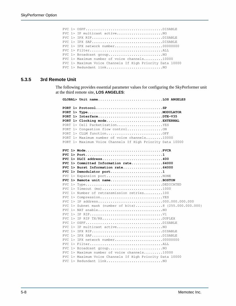
SkyPerformer Option
PVC 1> OSPF.....................................DISABLEPVC 1> IP multicast active......................NOPVC 1> IPX RIP..................................DISABLEPVC 1> IPX SAP..................................DISABLEPVC 1> IPX network number.......................00000000PVC 1> Filter...................................ALLPVC 1> Broadcast group..........................NOPVC 1> Maximum number of voice channels.........10000PVC 1> Maximum Voice Channels If High Priority Data 10000PVC 1> Redundant link...........................NO
5.3.5 3rd Remote UnitThe following provides essential parameter values for configuring the SkyPerformer unit at the third remote site, LOS ANGELES:
GLOBAL> Unit name...............................LOS ANGELES
PORT 1> Protocol................................SPPORT 1> Type....................................MODULATORPORT 1> Interface...............................DTE-V35PORT 1> Clocking mode...........................EXTERNALPORT 1> Cell Packetization......................YESPORT 1> Congestion flow control.................ONPORT 1> CLLM function...........................OFFPORT 1> Maximum number of voice channels........10000PORT 1> Maximum Voice Channels If High Priority Data 10000
PVC 1> Mode.....................................PVCRPVC 1> Port.....................................1PVC 1> DLCI address.............................400PVC 1> Committed Information rate...............64000PVC 1> Burst Information rate...................64000PVC 1> Demodulator port.........................1PVC 1> Expansion port...........................NONEPVC 1> Remote unit name.........................BOSTONPVC 1> Type.....................................DEDICATEDPVC 1> Timeout (ms).............................1000PVC 1> Number of retransmission retries.........100PVC 1> Compression..............................YESPVC 1> IP address...............................000.000.000.000PVC 1> Subnet mask (number of bits).............8 {255.000.000.000}PVC 1> NAT enable...............................NOPVC 1> IP RIP...................................V1PVC 1> IP RIP TX/RX.............................DUPLEXPVC 1> OSPF.....................................DISABLEPVC 1> IP multicast active......................NOPVC 1> IPX RIP..................................DISABLEPVC 1> IPX SAP..................................DISABLEPVC 1> IPX network number.......................00000000PVC 1> Filter...................................ALLPVC 1> Broadcast group..........................NOPVC 1> Maximum number of voice channels.........10000PVC 1> Maximum Voice Channels If High Priority Data 10000PVC 1> Redundant link...........................NO
5-8 Memotec Inc.
Index
AApplications 1-11
E1/T1 voice trunking 1-12example 5-2Internet backbone extension 1-14Public network extension 1-15voice/data enterprise network 1-12
Availabilityon NetPerformer products 2-7
CCables 2-6Configuration
application example 5-3data ports 3-2ports 3-2preparing for 2-7PVCs 3-10
Configuration and management access device 2-2Console 2-3Counters 4-8
DDC command
ports 4-8PVCs 4-8
DD command 4-2DE command 4-10
ports 4-10PVCs 4-10
Demodulatorfrequency 1-18, 2-6multiplexing traffic 3-12
DEMODULATOR portconfiguring 3-5, 3-8connection 2-6planning 2-4
Display commands 4-2Distributed star network 1-8DPORT command 4-5DPVC command 4-6DS command 4-3
ports 4-3PVC 4-5
EE1/T1 voice trunking 1-12Errors
displaying 4-10Example application 5-2Expansion chassis
configuration example 5-5ports 2-4
FFactory Setup command 2-7Features
NetPerformer 1-3SkyPerformer 1-3
Filtering, of packets 1-16, 1-17Frame Relay 1-3
switching 1-17FS command 2-7Full mesh network 1-10
HHardware platform 1-4Hybrid network 1-2, 1-11
IInformation signals, displaying 4-5Installation
checklist 2-2planning 2-4tips 2-6
Installation status 2-7Interface, displaying 4-4Internet backbone extension 1-14Intra-network transmissions 1-18
LLicense 2-7
See also Software license
MMain chassis ports 2-4Main headquarters
configuration example 5-3reception at 1-17
SkyPerformer Option 1
Management access methods 2-2Mode, of PVC 4-5Modem signals, displaying 4-4MODULATOR port
configuring 3-5, 3-6connection 2-6planning 2-4
Modulator port parameter 3-9
NNetPerformer
features 1-3platform 1-4
Networkdistributed star 1-8full mesh 1-10hybrid 1-2, 1-11partial mesh 1-9single star 1-7topologies 1-6
Network diagram 2-4example 5-2
Network management 2-2
OOperation 1-16
PPacket filtering 1-16, 1-17Parameter list
Modulator port, on SkyPerformer 3-9Type, on SkyPerformer port 3-6
ParametersPVCR PVC 3-14SP port 3-2SP-MULTIPLEX PVC 3-12
Partial meshnetwork 1-9topology 1-18
Performance 1-3Physical connections 2-6Planning installation 2-4Platform 1-4Port
activating 2-9counters 4-8DEMODULATOR 2-4, 2-6, 3-5, 3-8errors 4-10MODULATOR 2-4, 2-6, 3-5, 3-6planning installation 2-4protocol 3-2real-time status display 4-5Satellite 3-2
state, displaying 4-4status 4-3type 3-5
PowerCell 3-14Power-up 2-9Preparing the site 2-2Priority levels 2-5Product license 2-7
See also Software licenseProduct package 2-2Protocol 3-2
displaying 4-3Public network extension 1-15PVC
configuring 3-10counters 4-8errors 4-10PVCR 3-14real-time status display 4-6SP-MULTIPLEX 3-12status 4-5
PVCR PVC 3-14
RReceiving traffic 1-17, 1-18Remote site
configuration example 5-6, 5-7transmission to 1-16
Requirements 2-2network diagram 2-4satellite modems 1-2, 2-2
SSatellite link 3-2Satellite modems 1-2, 2-2Satellite networks 1-6
distributed star 1-8full mesh 1-10partial mesh 1-9single star 1-7
SC command 4-2SCPC 1-3, 1-11Single star network 1-7Site preparation 2-2SkyPerformer
features 1-3performance 1-3
SNMP agent 2-3Software license 2-7
agreement 2-7SP port 3-2Speed, displaying 4-4SP-MULTIPLEX PVC 3-12Star topology 1-16
2 Memotec Inc.
STC command 4-2
TTELNET access 2-3Topologies 1-6
distributed star 1-8full mesh 1-10partial mesh 1-9, 1-18single star 1-7star 1-16
Traffic priority 2-5Transmitting traffic 1-16, 1-18Type parameter 3-6Type, of port 3-5
UUnpacking 2-2
VVC command 4-2Voice/data enterprise network 1-12
SkyPerformer Option 3

REACH FURTHER. OFFER MORE.
Contact Memotec:
tel.: +1-514-738-4781e-mail: [email protected]
7755 Henri Bourassa Blvd. West Montreal, Quebec | Canada H4S 1P7 www.memotec.com