Embed Size (px)
Citation preview
1
National Department of Public Works
SKETCH PLAN COMMITTEE
MANUAL 2009
(VERSION 7)
September 2009
2
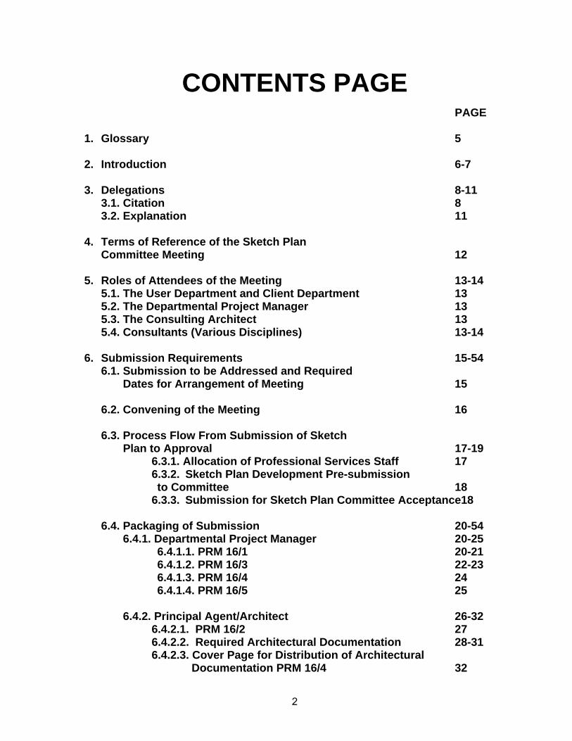
CONTENTS PAGE PAGE 1. Glossary 5
2. Introduction 6-7
3. Delegations 8-11
3.1. Citation 8 3.2. Explanation 11
4. Terms of Reference of the Sketch Plan Committee Meeting 12
5. Roles of Attendees of the Meeting 13-14 5.1. The User Department and Client Department 13 5.2. The Departmental Project Manager 13 5.3. The Consulting Architect 13 5.4. Consultants (Various Disciplines) 13-14
6. Submission Requirements 15-54 6.1. Submission to be Addressed and Required Dates for Arrangement of Meeting 15 6.2. Convening of the Meeting 16 6.3. Process Flow From Submission of Sketch Plan to Approval 17-19 6.3.1. Allocation of Professional Services Staff 17 6.3.2. Sketch Plan Development Pre-submission to Committee 18 6.3.3. Submission for Sketch Plan Committee Acceptance18 6.4. Packaging of Submission 20-54 6.4.1. Departmental Project Manager 20-25 6.4.1.1. PRM 16/1 20-21 6.4.1.2. PRM 16/3 22-23 6.4.1.3. PRM 16/4 24 6.4.1.4. PRM 16/5 25 6.4.2. Principal Agent/Architect 26-32 6.4.2.1. PRM 16/2 27 6.4.2.2. Required Architectural Documentation 28-31 6.4.2.3. Cover Page for Distribution of Architectural Documentation PRM 16/4 32
3
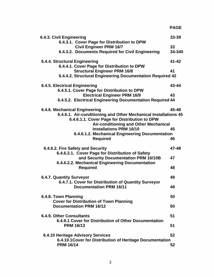
PAGE 6.4.3. Civil Engineering 33-39 6.4.3.1. Cover Page for Distribution to DPW Civil Engineer PRM 16/7 33 6.4.3.2. Documents Required for Civil Engineering 34-340 6.4.4. Structural Engineering 41-42 6.4.4.1. Cover Page for Distribution to DPW Structural Engineer PRM 16/8 41 6.4.4.2. Structural Engineering Documentation Required 42 6.4.5. Electrical Engineering 43-44 6.4.5.1. Cover Page for Distribution to DPW Electrical Engineer PRM 16/9 43 6.4.5.2. Electrical Engineering Documentation Required 44 6.4.6. Mechanical Engineering 45-48 6.4.6.1. Air-conditioning and Other Mechanical Installations 45 6.4.6.1.1. Cover Page for Distribution to DPW Air-conditioning and Other Mechanical Installations PRM 16/10 45 6.4.6.1.2. Mechanical Engineering Documentation Required 46 6.4.6.2. Fire Safety and Security 47-48 6.4.6.2.1. Cover Page for Distribution of Safety and Security Documentation PRM 16/10B 47 6.4.6.2.2. Mechanical Engineering Documentation Required 48 6.4.7. Quantity Surveyor 49 6.4.7.1. Cover for Distribution of Quantity Surveyor Documentation PRM 16/11 49 6.4.8. Town Planning 50 Cover for Distribution of Town Planning Documentation PRM 16/12 50 6.4.9. Other Consultants 51
6.4.9.1 Cover for Distribution of Other Documentation PRM 16/13 51
6.4.10 Heritage Advisory Services 52 6.4.10.1Cover for Distribution of Heritage Documentation PRM 16/14 52
4
PAGE
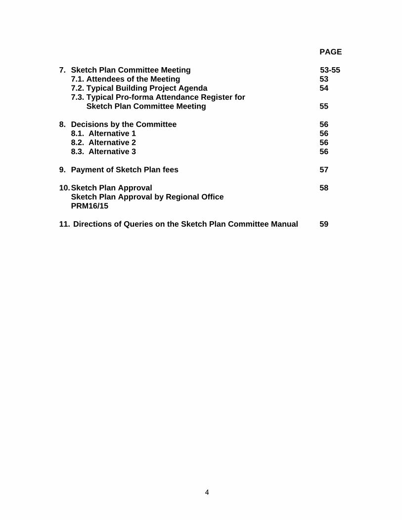
7. Sketch Plan Committee Meeting 53-55 7.1. Attendees of the Meeting 53 7.2. Typical Building Project Agenda 54 7.3. Typical Pro-forma Attendance Register for Sketch Plan Committee Meeting 55
8. Decisions by the Committee 56 8.1. Alternative 1 56 8.2. Alternative 2 56 8.3. Alternative 3 56
9. Payment of Sketch Plan fees 57 10. Sketch Plan Approval 58
Sketch Plan Approval by Regional Office PRM16/15
11. Directions of Queries on the Sketch Plan Committee Manual 59
5
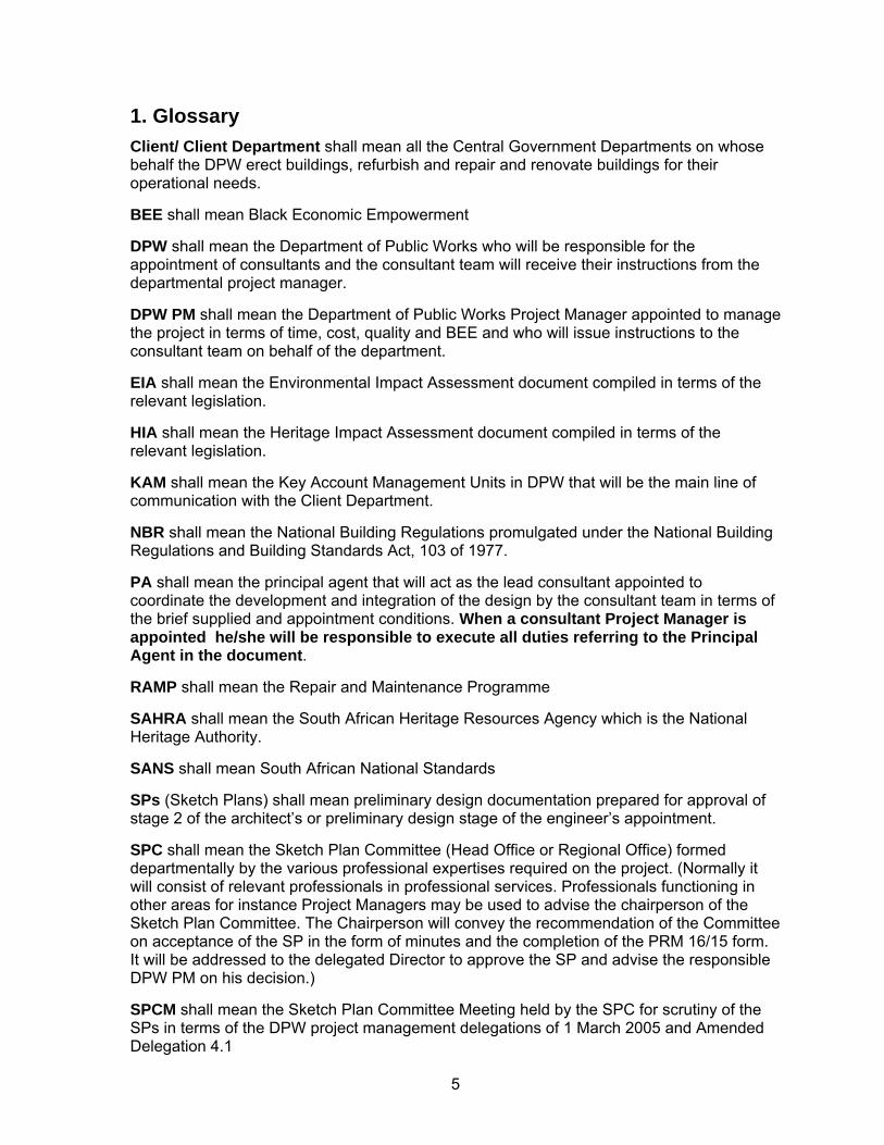
1. Glossary
Client/ Client Department shall mean all the Central Government Departments on whose behalf the DPW erect buildings, refurbish and repair and renovate buildings for their operational needs. BEE shall mean Black Economic Empowerment DPW shall mean the Department of Public Works who will be responsible for the appointment of consultants and the consultant team will receive their instructions from the departmental project manager. DPW PM shall mean the Department of Public Works Project Manager appointed to manage the project in terms of time, cost, quality and BEE and who will issue instructions to the consultant team on behalf of the department. EIA shall mean the Environmental Impact Assessment document compiled in terms of the relevant legislation. HIA shall mean the Heritage Impact Assessment document compiled in terms of the relevant legislation. KAM shall mean the Key Account Management Units in DPW that will be the main line of communication with the Client Department. NBR shall mean the National Building Regulations promulgated under the National Building Regulations and Building Standards Act, 103 of 1977. PA shall mean the principal agent that will act as the lead consultant appointed to coordinate the development and integration of the design by the consultant team in terms of the brief supplied and appointment conditions. When a consultant Project Manager is appointed he/she will be responsible to execute all duties referring to the Principal Agent in the document. RAMP shall mean the Repair and Maintenance Programme SAHRA shall mean the South African Heritage Resources Agency which is the National Heritage Authority. SANS shall mean South African National Standards SPs (Sketch Plans) shall mean preliminary design documentation prepared for approval of stage 2 of the architect’s or preliminary design stage of the engineer’s appointment. SPC shall mean the Sketch Plan Committee (Head Office or Regional Office) formed departmentally by the various professional expertises required on the project. (Normally it will consist of relevant professionals in professional services. Professionals functioning in other areas for instance Project Managers may be used to advise the chairperson of the Sketch Plan Committee. The Chairperson will convey the recommendation of the Committee on acceptance of the SP in the form of minutes and the completion of the PRM 16/15 form. It will be addressed to the delegated Director to approve the SP and advise the responsible DPW PM on his decision.) SPCM shall mean the Sketch Plan Committee Meeting held by the SPC for scrutiny of the SPs in terms of the DPW project management delegations of 1 March 2005 and Amended Delegation 4.1
6
2. Introduction This Sketch Plan Committee Manual has been prepared to prescribe to departmental project managers (DPW PM), principal agents (PA) and the consultant teams, about the development and mainly the submission of Sketch Plans (SP) to the Sketch Plan Committee for acceptance. The various disciplines’ consultant manuals must also be consulted. This manual mainly covers the following:
(a) Request for allocation of Professional Services officials to advise on specific projects.
(b) Interaction between Professional Services officials, DPW PM and the consultant team.
(c) Sketch Plan Committee submission requirements. (d) Sketch Plan Committee Meeting format and terms of reference. (e) Delegations and roles and responsibilities in respect of Sketch Plan
approval. In terms of the submission of Sketch Plans (SPs), should there be discrepancies with consultant manuals; the Sketch Plan Committee Manual must be followed. Where discrepancies are noted, the DPW PM must be notified in order to ensure rectification. The interaction advised on projects with officials before submission of SP’s is to maximize the success rate of submissions. Due to the onerous task to ensure that all disciplines are represented at the set meetings, all SPC meetings will convene on Fridays. Staff will be advised by the agenda circulated by the office of the chairperson, the week before the SPC meetings. Submissions received in the past have often been found to have been incomplete and the packaging of the submission for scrutiny have made the duplication of copies and distribution to the relevant disciplines very time consuming. This manual specifies the various disciplines’ requirements to enable a quick turnaround and high success rate for submissions. Incomplete submissions and/or uncoordinated designs inevitably lead to re-convening of SPC meetings for the same projects. Due to the high number of attendees required for these meetings, it must be managed properly (All disciplines of Professional Services, Key Account Management (KAM), DPW PM, clients and a representative of all disciplines of the consultant team). Submissions that are non-compliant with the Manual requirements will therefore not be accepted until full compliance has been achieved, in order to avoid the unnecessary reconvening of meetings because of the above-mentioned. The DPW PM must ensure the submission of the outstanding documentation. Noting the above-mentioned and the pressure on Project Managers to deliver projects, the manual enables the 3 week submission period for the convening of the SPC meeting to be reduced to 6 working days from receipt. This is on the assumption that the necessary interaction has taken place with departmental professional counterparts, if not, the 3 week time frame will apply.
7
The Manual sets out the various steps from the start of the project to ensure easier interaction with departmental counterparts. This should avoid the stop-start effect experienced on various projects when there is not clear guidance for consultants for the development and integration of design concepts. A pro-active approach is therefore sought in the development of designs and SPs, to enable appropriate co-ordination of designs to be effected quickly and in line with various relevant Acts and requirements, and have a high success rate of acceptance of Sketch Plan submission.
8
3. Delegations 3.1. Citation Please find an extract of the of the Project Management delegations as revised.
AMENDED DELEGATION 4.1
4.1 Approval and amendments of: a) sketch plans, in the case of building project, or
b) preliminary design report, in the case of engineering project. Lowest Level of
Allocated Power Maximum Financial Level of Power
Condition(s) Pertaining to Exercising of Power
D/Project & M D/Prof Services D/Proj Man Sup D/Spec Projects TM
Unlimited
Upon opinion expressed by a Sketch Plan Committee (conditional to the general Notes and Conditions below).
General Notes and Conditions 1. Sketch plans and/or preliminary design reports of all projects consisting of
a) new work, b) upgrading, new additions or alterations to existing buildings /installations
/engineering infrastructure c) Repair and renovation, or
d) RAMP must be subjected to the scrutiny and comment of the Sketch Plan Com. as outlined in the table below:
Work Type Category Sub Category Monetary Parameter Minimum Level Committee to consider design proposals
A1 R0 – R0.5M 4 A2 R0.5 – R10M 3 A3 R10M – R20M 2 A4 R20M & above 1
A
A5 Master Planning 1 B1 R0 – R2M 3 B2 R2 – R20M 2
New work
B
B3 R20M & above 1 C1 R0 – R5M 3 C2 R5M – R20M 2
Repair and Renovation work
C
C3 R20M & above 1 D1 R0 – R5M 3 D2 R5M – R20M 2
RAMP D
D3 R20M & above 1
ee legend and explanatory notes at the end to be able to read this table –
9
If serious or far-reaching comments were made by the Sketch Plan Com, and the Professional Team was required to re-submit an amended/revised design, such amended/revised design must first be completed before final approval stages, referred to below, can be considered. PM to submit revised documentation for a further round of scrutiny at the Sketch Plan Com.
The final approval power (delegated power as above) must only be executed subject to the comments by the Sketch Plan Com, design documents being in compliance with the prescribed space norms and cost limits, funds being available and the Client Department having expressed its satisfaction and granted written approval on the drawings/report.
Approvals given against advise of Professional Services/ Sketch Plan Com will be at the risk of the approving authority in terms of this delegated power 5. Later amendments to design proposals, after design has been approved, must not be of such extensive nature that the project constitutes a new project or new design and may not exceed 5% of the project estimate. PM to supply full motivation as to the necessity for the amendment. Amendments may not violate space norms and cost limit set for the project. If the 5% margin stated herein is exceeded, the comments of the Sketch Plan Com are to be obtained again.
Amendment to delegation 4.1 as contained the document entitled: DELEGATION OF POWERS, DUTIES AND FUNCTIONS WITH REGARD TO THE MANAGEMENT OF SITE CLEARANCE-, BUILDING-, LEASING- OR ENGINEERING PROJECTS, VESTED IN THE DIRECTOR-GENERAL BY VIRTUE OF HIS ROLE AS DIRECTOR-GENERAL / ACCOUNTING OFFICER OF THE DEPARTMENT OF PUBLIC WORKS. Legend: Work Type Category Sub Category Monetary
Parameter A1 R0 – R0.5M A2 R0.5 – R10M A3 R10M – R20M A4 R20M & above
A Green field (complete new buildings/engineering installations or new additions to existing) (or Master Planning of an area/site incl. existing facilities)
A5 Master Planning B1 R0 – R2M B2 R2 – R20M
New work
B To existing facility (upgrading and/or alterations resulting in substantial changes to existing buildings/engineering installations) B3 R20M & above
C1 R0 – R5M C2 R5M – R20M
Repair and Renovation work
C Repair/replace what is broken / dysfunctional (without effecting any substantial changes to building appearance, circulation, air flows, etc)
C3 R20M & above
D1 R0 – R5M D2 R5M – R20M
RAMP D Repair/replace what is broken / dysfunctional and pro-actively maintain for a certain fixed period (without any new work included in the project)
D3 R20M & above
Criteria 1: One part of the criteria that can not be relaxed is the need to have all disciplines represented on such Committee if the project entails the full spectrum of activities. These are: Architecture, Quantity Surveying, Civil-, Structural-, Electrical-, Security and Fire (Safety) and Mechanical Engineering and Town Planning. Criteria 2: Relaxation is only permitted if certain work is not part of the project eg: if no mechanical work is part of the contract, a representative from the mechanical discipline will not be required to sit with the Committee, etc. Criteria 3: It must be accepted that none of the Committees (either Head – or Regional Offices) will be able to have professional staff for all disciplines sitting on the Committee, nor that technical staff will
10
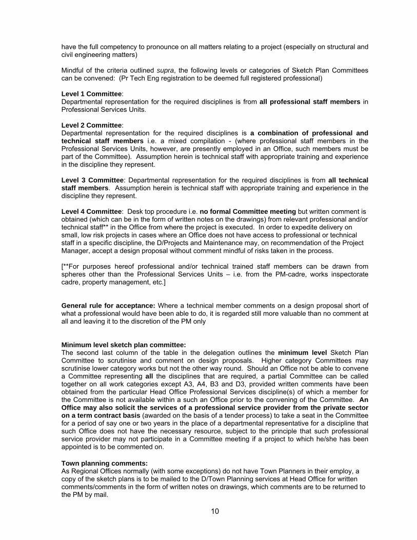
have the full competency to pronounce on all matters relating to a project (especially on structural and civil engineering matters) Mindful of the criteria outlined supra, the following levels or categories of Sketch Plan Committees can be convened: (Pr Tech Eng registration to be deemed full registered professional) Level 1 Committee: Departmental representation for the required disciplines is from all professional staff members in Professional Services Units. Level 2 Committee: Departmental representation for the required disciplines is a combination of professional and technical staff members i.e. a mixed compilation - (where professional staff members in the Professional Services Units, however, are presently employed in an Office, such members must be part of the Committee). Assumption herein is technical staff with appropriate training and experience in the discipline they represent. Level 3 Committee: Departmental representation for the required disciplines is from all technical staff members. Assumption herein is technical staff with appropriate training and experience in the discipline they represent. Level 4 Committee: Desk top procedure i.e. no formal Committee meeting but written comment is obtained (which can be in the form of written notes on the drawings) from relevant professional and/or technical staff** in the Office from where the project is executed. In order to expedite delivery on small, low risk projects in cases where an Office does not have access to professional or technical staff in a specific discipline, the D/Projects and Maintenance may, on recommendation of the Project Manager, accept a design proposal without comment mindful of risks taken in the process. [**For purposes hereof professional and/or technical trained staff members can be drawn from spheres other than the Professional Services Units – i.e. from the PM-cadre, works inspectorate cadre, property management, etc.] General rule for acceptance: Where a technical member comments on a design proposal short of what a professional would have been able to do, it is regarded still more valuable than no comment at all and leaving it to the discretion of the PM only Minimum level sketch plan committee: The second last column of the table in the delegation outlines the minimum level Sketch Plan Committee to scrutinise and comment on design proposals. Higher category Committees may scrutinise lower category works but not the other way round. Should an Office not be able to convene a Committee representing all the disciplines that are required, a partial Committee can be called together on all work categories except A3, A4, B3 and D3, provided written comments have been obtained from the particular Head Office Professional Services discipline(s) of which a member for the Committee is not available within a such an Office prior to the convening of the Committee. An Office may also solicit the services of a professional service provider from the private sector on a term contract basis (awarded on the basis of a tender process) to take a seat in the Committee for a period of say one or two years in the place of a departmental representative for a discipline that such Office does not have the necessary resource, subject to the principle that such professional service provider may not participate in a Committee meeting if a project to which he/she has been appointed is to be commented on. Town planning comments: As Regional Offices normally (with some exceptions) do not have Town Planners in their employ, a copy of the sketch plans is to be mailed to the D/Town Planning services at Head Office for written comments/comments in the form of written notes on drawings, which comments are to be returned to the PM by mail.
11
3.2. Explanation a) The personnel executing projects must act in terms of their delegations and
the duties that should be fulfilled , which are outlined above.
Approval and/or amendments thereto of sketch plans and the preliminary design report and drawing(s) are delegated to the Directors: Projects or Special & Major Projects. The approval is subject to the conditions above.
(b) The PA (who usually is the architect or a consultant PM if relevant) must act in terms of his appointment and interact with the DPW PM as well as the other consultants.
(c) All consultants must act in terms of their appointments and liaise with the PA during the execution of their duties through DPW PMs.
(d) The opinion passed by the SPC is given in the form of a recommendation
captured in the minutes of the meeting which the DPW PM can present to his/her responsible Director. The approval given by the Director should not be construed as having relieved the consultants of any of their duties and/or responsibilities in terms of the conditions of their contracts with the department.
(e) For new RAMP projects the SP documentation will be based on the Status Quo report and Planning Instructions based on acceptance of scope and budget approval by the Client. The certification of a competent DPW PM/ Works Inspector of the true reflection of the work that is required is proposed. Guard against unnecessary specification of repairs on these projects. The appropriately skilled SPC must assess the submission and delegated Director to approve. In the case of a follow-up RAMP, the close-out report can be used with the new project planning instruction and similar documentation and processes up to approval must be followed.
12
4. Terms of Reference of the Sketch Plan Committee The DPW PM has to comply with the afore-mentioned delegations for SP approval for projects, before proceeding to the following phase of documentation.
a) Acceptance of projects falling in the category in terms of the delegation for scrutiny by the SPC will be formulated in the form of a recommendation (minutes of the meeting) on which the responsible Director: Special Projects (Head Office) or Director: Projects (Regional Office) of the DPW PM can base his decision to approve the SP or not. The PA has to ensure that an integrated design proposal has been submitted. The design will therefore allow for necessary engineering services at a SP level. This means that the preliminary engineering report and design requirements have been incorporated into the design. The detail of information on the architects drawing should be in line with PRM 16/2 which need to be included into the submission.
b) The SP submission (drawings and preliminary design reports) will be assessed based on the available information at SP stage for compliance with:
1. Approved planning instruction (including space norms, cost limits and special requirements)
2. Town planning and EIA requirements 3. Client requirements and acceptance 4. Departmental requirements and National Building Regulations 5. Functionality of the design 6. Buildability 7. Heritage requirements (HIA if applicable) 8. Value for money 9. Cost estimates and space norm and cost limit reconciliations 10. Integration of various disciplines’ designs 11. Disability access & facilities 12. Energy efficiency and sustainability 13. Procurement options – to be recommended by SPC during the
meeting
c) The terms of reference of the meeting is to establish whether the architect’s design is sufficiently advanced to be accepted as having complied with the minimum requirements of stage 2 of the work stage. The description of work stage 2 shall be as described in the Department’s letter of appointment. Approval of the SPs by the Director will entitle consultants to payment for that stage of the work.
13
5. Roles of Attendees of the Meeting 5.1. The Client Department/ User Department
The client is the department for which the facility is designed and normally the occupier (i.e. SAPS, Justice, etc.) of the building. The client department should sign off the architect’s stage 2 drawings, indicating approval of circulation, room sizes and the positioning or grouping of rooms. If the client department can not attend the SPCM, their signed drawings must be supplied at the meeting. This approval by client departments should in no way be construed as approval by DPW. Architectural, technical and engineering matters still require scrutiny by the professionals of the Department.
5.2. The Departmental Project Manager The PA informs the DPW PM that the work of the architect and the consultants is sufficiently progressed to warrant a SPCM. The DPW PM, after verifying the status then requests the PA to arrange the packaging and submission of the SP in terms of the Sketch Plan Committee Manual.
5.3. The Consulting Architect The architect’s work should be in line with the work stages set out in the Departmental Architect’s Manual and the contract with the Department, the latter also at times referred to as the Letter of Appointment. Kindly note the Department’s work stages do not coincide with those of the South African Council for the Architectural Profession in all respects.
5.4. Consultants (various disciplines) The consultants are expected to interact with their professional counterparts in the DPW SPC, until satisfaction has been reached on the design. The consultation to be via the DPW PM or as agreed with him. (Note par. 6.3.2, page 17 for detail) Typically but not exhaustively, the disciplines involved in a building project would involve the following professions in the DPW SPC: a) Architects, quantity surveyors, civil, structural, electrical and mechanical
engineers, town-planning (for site clearance issues) and the DPW PM. Other disciplines, such as security specialists, acoustic engineers, etc. may be appointed from time to time. The PA should obtain a list of professional services officials (see PRM 16/1), allocated to the project from the DPW PM, in order to facilitate professional inputs between them and the consultant team. It should be noted that site clearance issues should be ascertained by the DPW PM prior to the appointment of consultants. The available document should be compared with actual conditions on site, before the consultants start with their work. Should any anomalies be found, these need to be taken up with the Director: Town Planning at Head Office without delay. (Consultant’s responsibility)
It is expected of the PA (normally the consulting architect) to ensure that the consultants have liaised with their professional counterparts at the DPW and that the resulting information is made available to him/her for incorporation in
14
his/her documentation. All designs and comments to be integrated into the final SPCM submission. It is expected of each consultant to obtain all information necessary (guidelines/specifications/handbooks etc.) to execute his/her professional duties in terms of his/her appointment. All legislation pertaining to the professions as well as the work relating to the project should be complied with. The PA/Architect should be provided with all necessary information by the consultants in order to successfully complete the work required of him/her at work stage 2 levels. His professional counterpart at the DPW should be provided with all the necessary information required for the successful evaluation of the project, by way of reports, drawings, estimates etc.
15
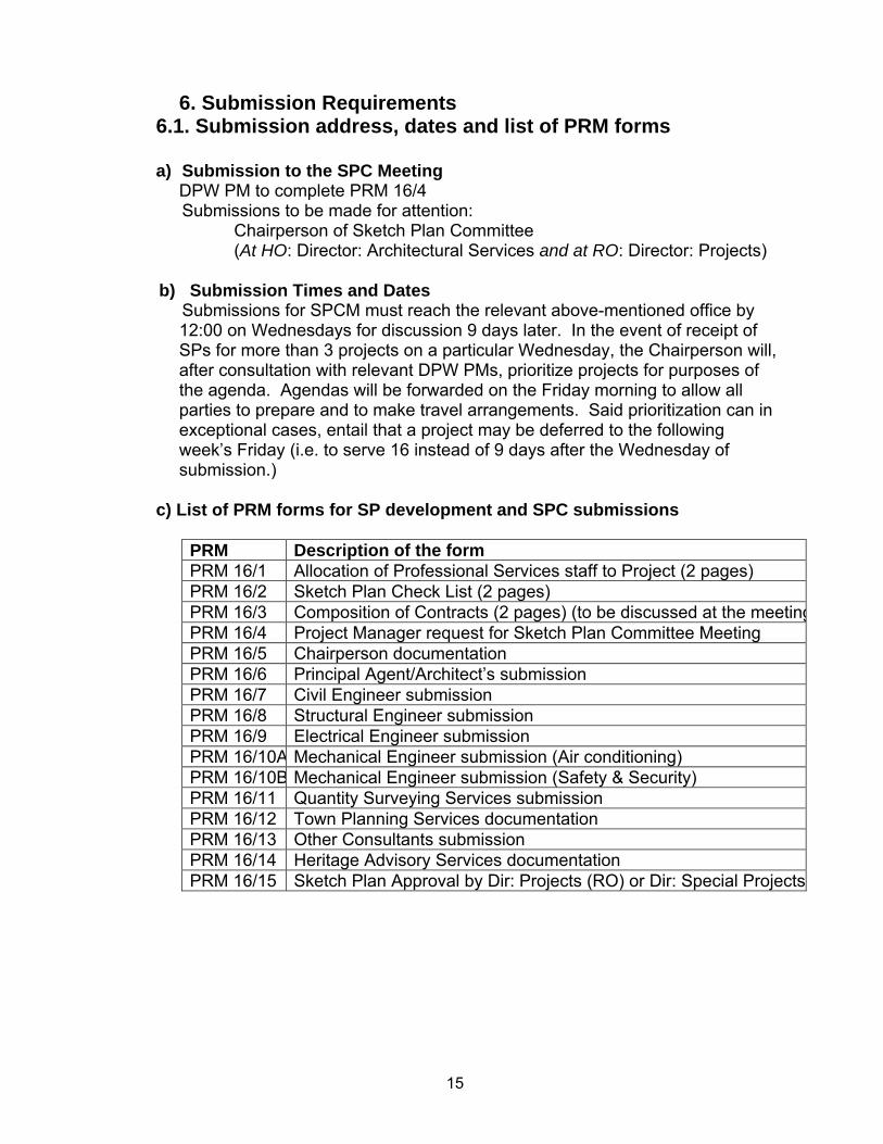
6. Submission Requirements 6.1. Submission address, dates and list of PRM forms
a) Submission to the SPC Meeting
DPW PM to complete PRM 16/4 Submissions to be made for attention:
Chairperson of Sketch Plan Committee (At HO: Director: Architectural Services and at RO: Director: Projects)
b) Submission Times and Dates
Submissions for SPCM must reach the relevant above-mentioned office by 12:00 on Wednesdays for discussion 9 days later. In the event of receipt of SPs for more than 3 projects on a particular Wednesday, the Chairperson will, after consultation with relevant DPW PMs, prioritize projects for purposes of the agenda. Agendas will be forwarded on the Friday morning to allow all parties to prepare and to make travel arrangements. Said prioritization can in exceptional cases, entail that a project may be deferred to the following week’s Friday (i.e. to serve 16 instead of 9 days after the Wednesday of submission.)
c) List of PRM forms for SP development and SPC submissions PRM Description of the form PRM 16/1 Allocation of Professional Services staff to Project (2 pages) PRM 16/2 Sketch Plan Check List (2 pages) PRM 16/3 Composition of Contracts (2 pages) (to be discussed at the meetingPRM 16/4 Project Manager request for Sketch Plan Committee Meeting PRM 16/5 Chairperson documentation PRM 16/6 Principal Agent/Architect’s submission PRM 16/7 Civil Engineer submission PRM 16/8 Structural Engineer submission PRM 16/9 Electrical Engineer submission PRM 16/10A Mechanical Engineer submission (Air conditioning) PRM 16/10B Mechanical Engineer submission (Safety & Security) PRM 16/11 Quantity Surveying Services submission PRM 16/12 Town Planning Services documentation PRM 16/13 Other Consultants submission PRM 16/14 Heritage Advisory Services documentation PRM 16/15 Sketch Plan Approval by Dir: Projects (RO) or Dir: Special Projects
16
6.2. Convening of the Meeting a) The PA (usually the architect) informs the DPW PM that he has liaised with
the Departmental architect and that all the consultants have liaised with their counterparts at the DPW. The PA will complete relevant forms in the manual and ensure the required formats and packaging requirements have been complied with.
b) The PA further has to report to the DPW PM that he is satisfied with the outcomes of the liaison process and that a SPCM may be convened.
c) The DPW PM will assess the submission received and complete the PRM 16/4 form. The relevant Director: Projects /Regional Manager to approve the submission.
d) The Chairperson requires sufficient time to coordinate the meetings and to notify officials for attendance. Fridays are set aside for meetings. An agenda to this effect will be circulated to officials to attend and to DPW PM who will notify the consultant team and the Client representative.
e) The SPC is chaired by the Director: Architectural Services or a delegated architect at HO and alternatively, by the Director: Projects or delegated architect at the RO. For the engineering projects, the relevant Director: Engineering at HO and the Director: Projects at the RO will chair or the delegated professional engineer. If the project is an engineering project it must be indicated accordingly on the covering correspondence.
f) The Director: Architectural Services/ Director: Projects / Chairperson of the SPCM retains the prerogative to determine the agenda. The duration of a SPCM will be determined by the Chairperson. This will generally be up to 2 hours, depending on the size and complexity of the project.
g) Special requests for SPCM to be conducted with less that 9 days’ notice are to be directed in writing to the Chief Director: Professional Services by the relevant Manager for HO projects (or to the Regional Manager at the Regional Office by the relevant Director) for consideration.

17
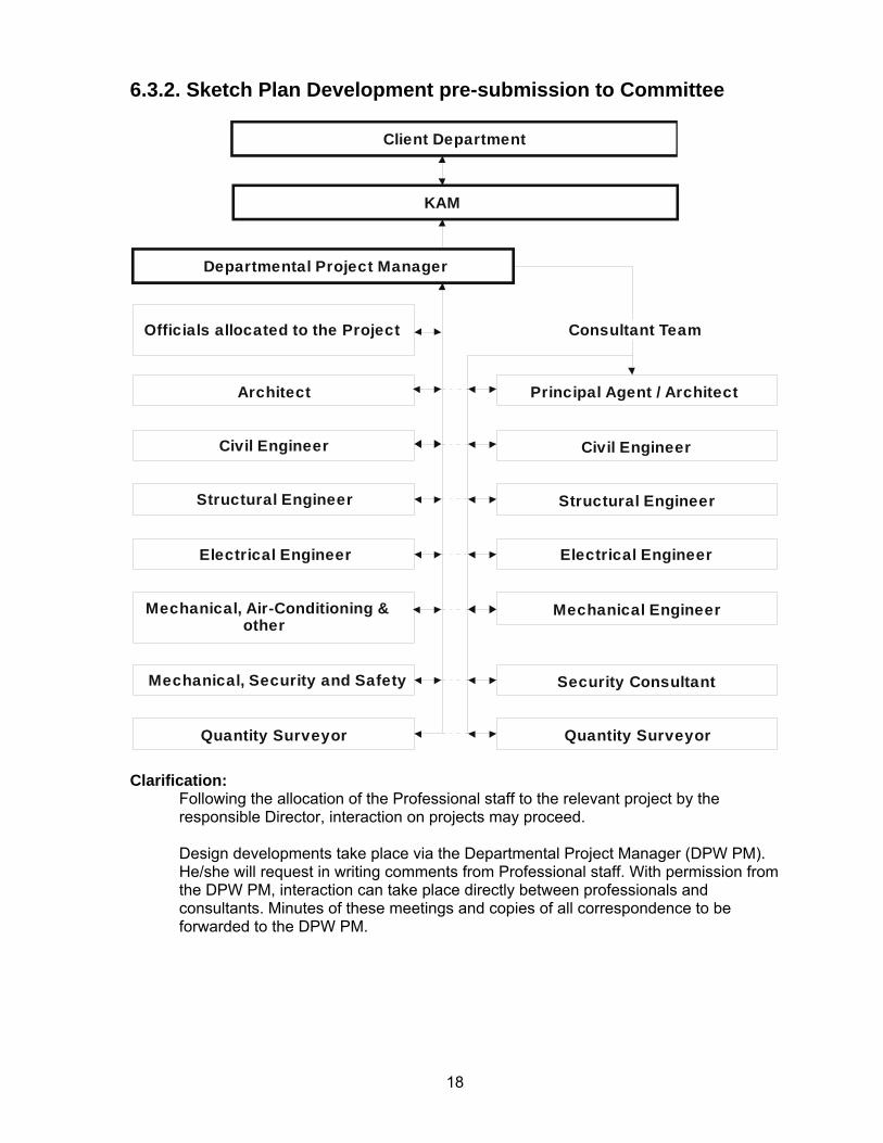
6.3. Sketch Plan Development Pre-submission to Committee 6.3.1. Allocation of Professional Services Staff
18
6.3.2. Sketch Plan Development pre-submission to Committee
Client Department
KAM
Architect
Civil Engineer
Structural Engineer
Electrical Engineer
Quantity Surveyor Quantity Surveyor
Mechanical, Air-Conditioning & other
Mechanical, Security and Safety Security Consultant
Departmental Project Manager
Officials allocated to the Project Consultant Team
Civil Engineer
Structural Engineer
Electrical Engineer
Mechanical Engineer
Principal Agent / Architect
Clarification:
Following the allocation of the Professional staff to the relevant project by the responsible Director, interaction on projects may proceed. Design developments take place via the Departmental Project Manager (DPW PM). He/she will request in writing comments from Professional staff. With permission from the DPW PM, interaction can take place directly between professionals and consultants. Minutes of these meetings and copies of all correspondence to be forwarded to the DPW PM.
19
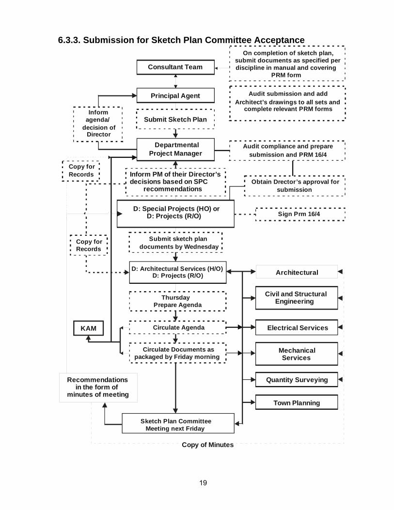
6.3.3. Submission for Sketch Plan Committee Acceptance
Departmental
Consultant Team
Civil and Structural Engineering
Architectural
Electrical Services
Quantity Surveying
Town Planning
Recommendations in the form ofminutes of meeting
Mechanical Services
D: Special Projects (HO) or D: Projects (R/O)
Principal Agent
Submit Sketch Plan
Project Manager
Inform PM of their Director’sdecisions based on SPC recommendations
On completion of sketch plan,submit documents as specified perdiscipline in manual and covering PRM form
Audit submission and addArchitect’s drawings to all sets and
complete relevant PRM formsInformagenda/
decision ofDirector
Audit compliance and preparesubmission and PRM 16/4
Obtain Drector’s approval for submission
Copy forRecords
Copy forRecords
Sign Prm 16/4
Submit sketch plandocuments by Wednesday
D: Architectural Services (H/O)D: Projects (R/O)
ThursdayPrepare Agenda
Circulate Agenda
Circulate Documents aspackaged by Friday morning
Sketch Plan Committee Meeting next Friday
KAM
Copy of Minutes
20
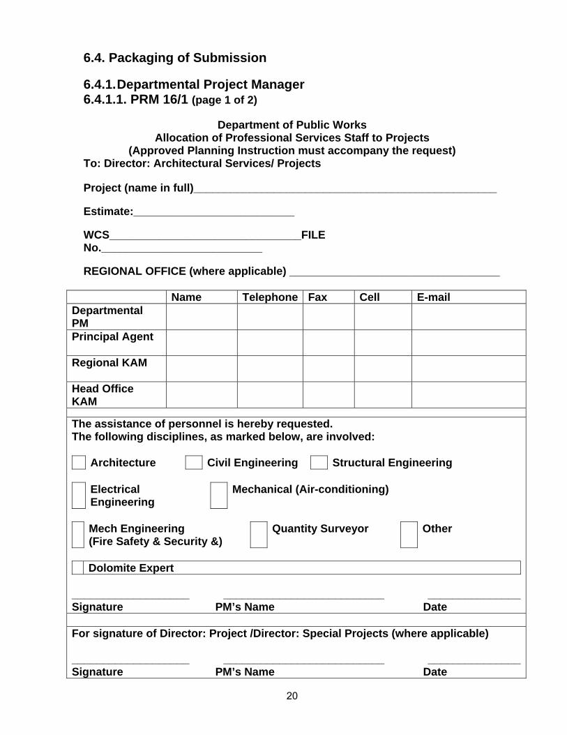
6.4. Packaging of Submission 6.4.1. Departmental Project Manager 6.4.1.1. PRM 16/1 (page 1 of 2)
Department of Public Works Allocation of Professional Services Staff to Projects
(Approved Planning Instruction must accompany the request) To: Director: Architectural Services/ Projects Project (name in full)_________________________________________________ Estimate:__________________________ WCS_______________________________FILE No.__________________________ REGIONAL OFFICE (where applicable) __________________________________
Name Telephone Fax Cell E-mail Departmental PM
Principal Agent
Regional KAM
Head Office KAM
The assistance of personnel is hereby requested. The following disciplines, as marked below, are involved: Architecture Civil Engineering Structural Engineering
Electrical
Engineering Mechanical (Air-conditioning)
Mech Engineering
(Fire Safety & Security &) Quantity Surveyor Other
Dolomite Expert
___________________ __________________________ _______________Signature PM’s Name Date For signature of Director: Project /Director: Special Projects (where applicable) ___________________ __________________________ _______________Signature PM’s Name Date
21
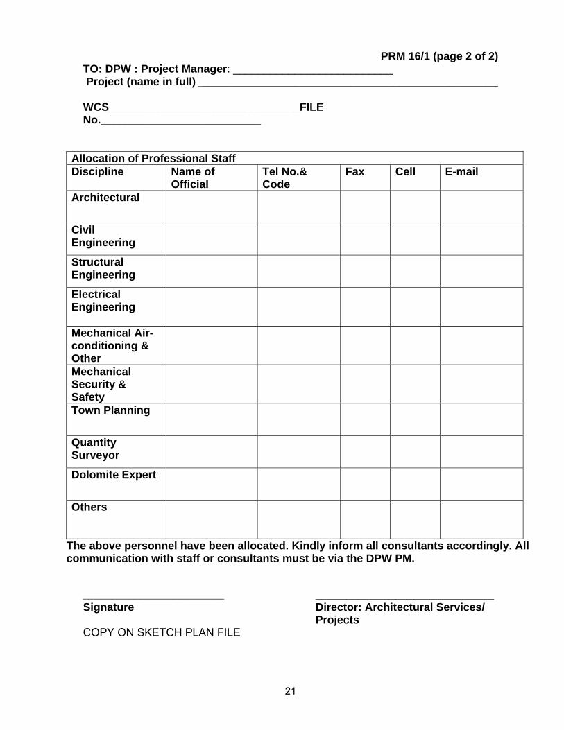
PRM 16/1 (page 2 of 2) TO: DPW : Project Manager: __________________________ Project (name in full) _________________________________________________ WCS_______________________________FILE No.__________________________
Allocation of Professional Staff Discipline Name of
Official Tel No.& Code
Fax Cell E-mail
Architectural
Civil Engineering
Structural Engineering
Electrical Engineering
Mechanical Air-conditioning & Other
Mechanical Security & Safety
Town Planning
Quantity Surveyor
Dolomite Expert
Others
The above personnel have been allocated. Kindly inform all consultants accordingly. All communication with staff or consultants must be via the DPW PM.
_________________________ _____________________________ Signature Director: Architectural Services/
Projects COPY ON SKETCH PLAN FILE
22
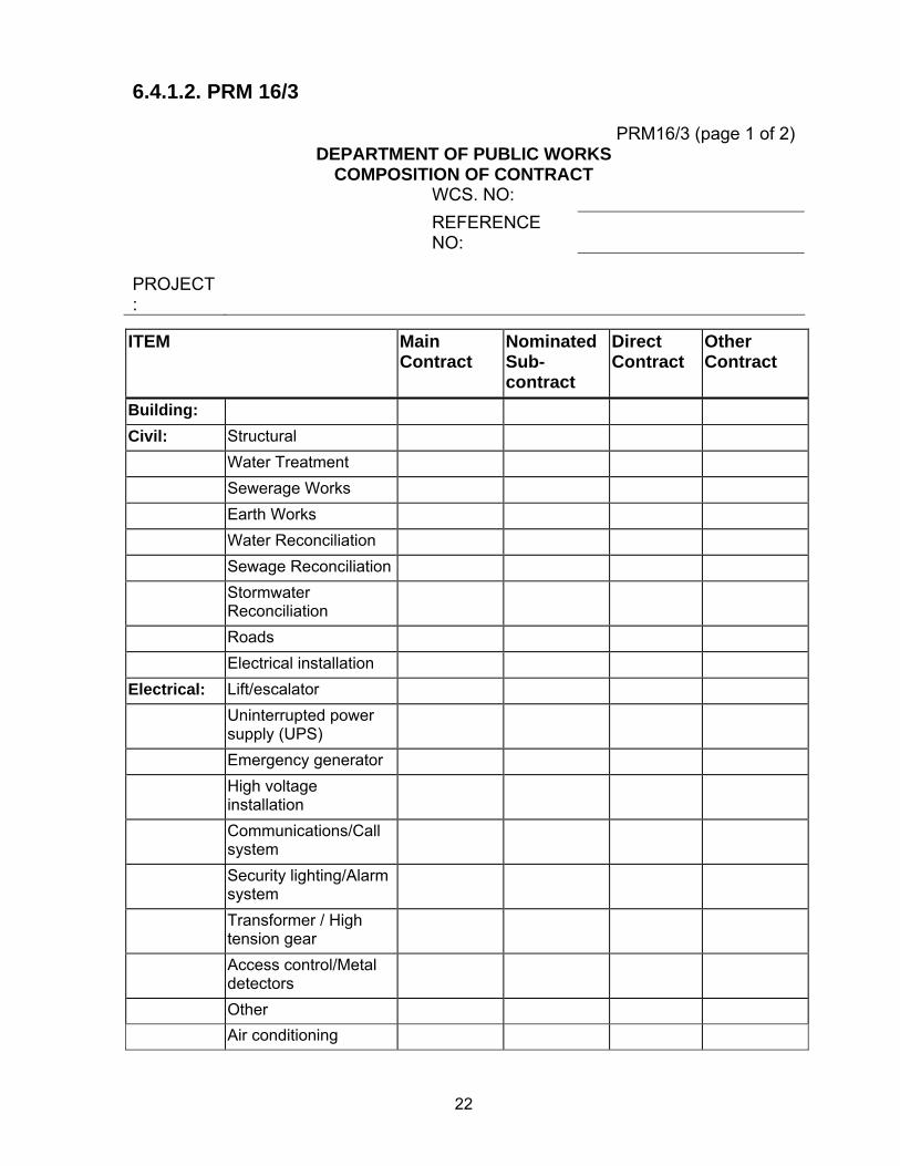
6.4.1.2. PRM 16/3
PRM16/3 (page 1 of 2) DEPARTMENT OF PUBLIC WORKS
COMPOSITION OF CONTRACT WCS. NO: REFERENCE
NO:
PROJECT:
ITEM Main Contract
Nominated Sub-contract
Direct Contract
Other Contract
Building: Civil: Structural Water Treatment Sewerage Works Earth Works Water Reconciliation Sewage Reconciliation Stormwater
Reconciliation
Roads Electrical installation Electrical: Lift/escalator Uninterrupted power
supply (UPS)
Emergency generator High voltage
installation
Communications/Call system
Security lighting/Alarm system
Transformer / High tension gear
Access control/Metal detectors
Other Air conditioning
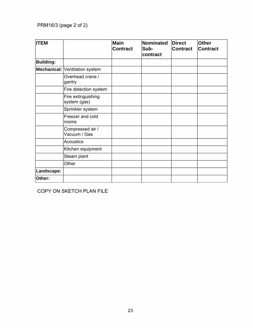
23
PRM16/3 (page 2 of 2) ITEM Main
Contract Nominated Sub-contract
Direct Contract
Other Contract
Building: Mechanical: Ventilation system Overhead crane /
gantry
Fire detection system Fire extinguishing
system (gas)
Sprinkler system Freezer and cold
rooms
Compressed air / Vacuum / Gas
Acoustics Kitchen equipment Steam plant Other Landscape: Other: COPY ON SKETCH PLAN FILE
24
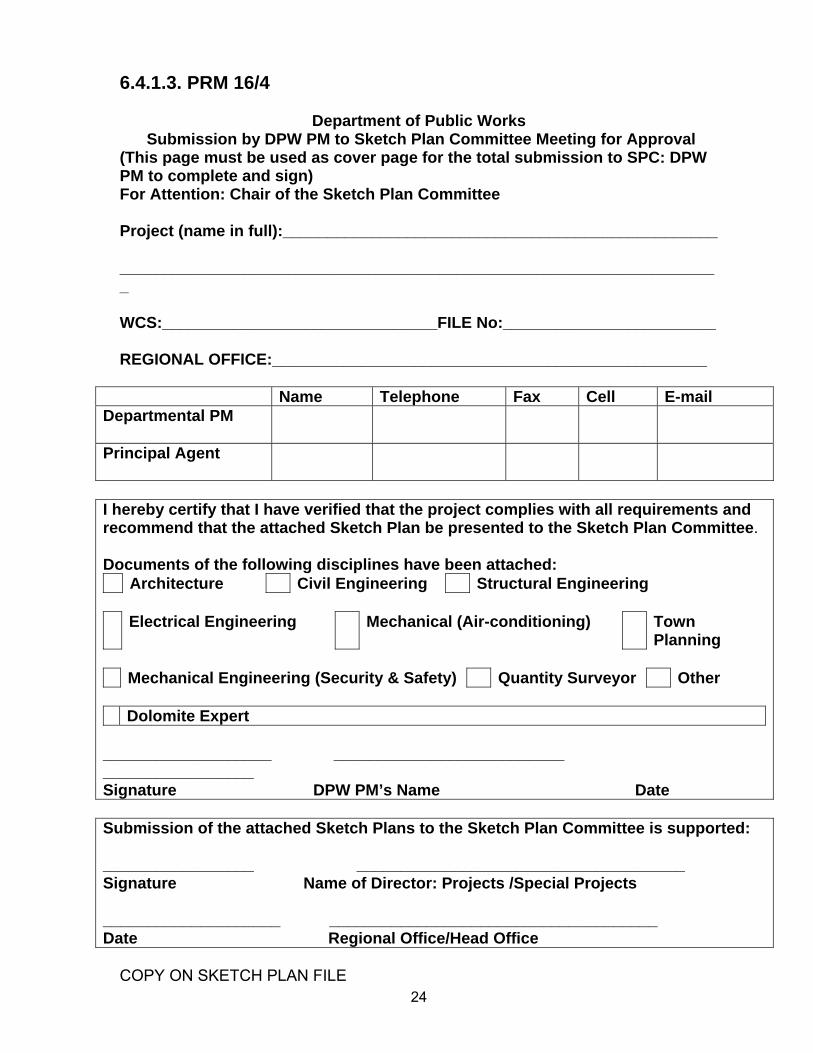
6.4.1.3. PRM 16/4
Department of Public Works Submission by DPW PM to Sketch Plan Committee Meeting for Approval
(This page must be used as cover page for the total submission to SPC: DPW PM to complete and sign) For Attention: Chair of the Sketch Plan Committee Project (name in full):_________________________________________________ ____________________________________________________________________ WCS:_______________________________FILE No:________________________ REGIONAL OFFICE:_________________________________________________
Name Telephone Fax Cell E-mail Departmental PM
Principal Agent
I hereby certify that I have verified that the project complies with all requirements and recommend that the attached Sketch Plan be presented to the Sketch Plan Committee. Documents of the following disciplines have been attached: Architecture Civil Engineering Structural Engineering
Electrical Engineering Mechanical (Air-conditioning) Town
Planning Mechanical Engineering (Security & Safety) Quantity Surveyor Other
Dolomite Expert
___________________ __________________________ _________________ Signature DPW PM’s Name Date Submission of the attached Sketch Plans to the Sketch Plan Committee is supported: _________________ _____________________________________ Signature Name of Director: Projects /Special Projects ____________________ _____________________________________ Date Regional Office/Head Office
COPY ON SKETCH PLAN FILE
25
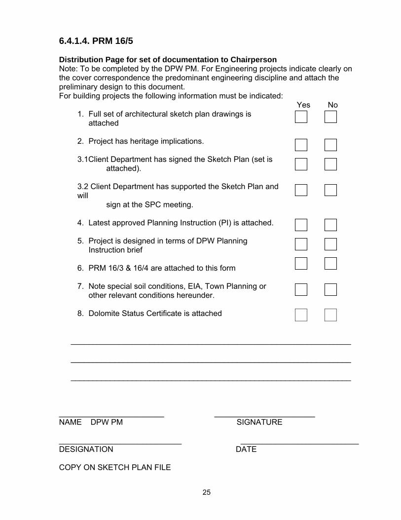
6.4.1.4. PRM 16/5 Distribution Page for set of documentation to Chairperson Note: To be completed by the DPW PM. For Engineering projects indicate clearly on the cover correspondence the predominant engineering discipline and attach the preliminary design to this document. For building projects the following information must be indicated:
Yes No 1. Full set of architectural sketch plan drawings is
attached
2. Project has heritage implications.
3.1Client Department has signed the Sketch Plan (set is attached).
3.2 Client Department has supported the Sketch Plan and will sign at the SPC meeting.
4. Latest approved Planning Instruction (PI) is attached.
5. Project is designed in terms of DPW Planning
Instruction brief
6. PRM 16/3 & 16/4 are attached to this form
7. Note special soil conditions, EIA, Town Planning or other relevant conditions hereunder.
8. Dolomite Status Certificate is attached
________________________________________________________________ ________________________________________________________________ ________________________________________________________________
________________________ _______________________ NAME DPW PM SIGNATURE ____________________________ ___________________________ DESIGNATION DATE COPY ON SKETCH PLAN FILE
26
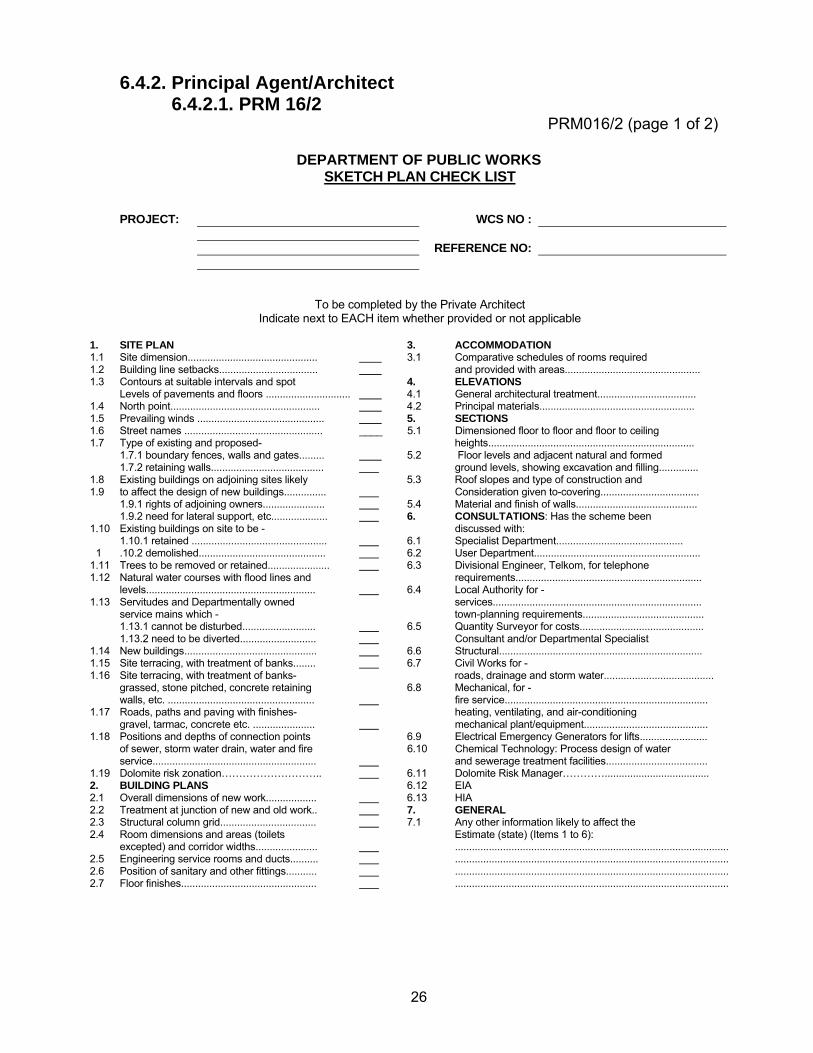
6.4.2. Principal Agent/Architect 6.4.2.1. PRM 16/2
PRM016/2 (page 1 of 2)
DEPARTMENT OF PUBLIC WORKS SKETCH PLAN CHECK LIST PROJECT: WCS NO : REFERENCE NO: To be completed by the Private Architect Indicate next to EACH item whether provided or not applicable
1. SITE PLAN 3. ACCOMMODATION 1.1 Site dimension.............................................. 3.1 Comparative schedules of rooms required 1.2 Building line setbacks................................... and provided with areas................................................ 1.3 Contours at suitable intervals and spot 4. ELEVATIONS Levels of pavements and floors .............................. 4.1 General architectural treatment................................... 1.4 North point..................................................... 4.2 Principal materials....................................................... 1.5 Prevailing winds ............................................. 5. SECTIONS 1.6 Street names ................................................. ____ 5.1 Dimensioned floor to floor and floor to ceiling 1.7 Type of existing and proposed- heights......................................................................... 1.7.1 boundary fences, walls and gates......... 5.2 Floor levels and adjacent natural and formed 1.7.2 retaining walls........................................ ground levels, showing excavation and filling.............. 1.8 Existing buildings on adjoining sites likely 5.3 Roof slopes and type of construction and 1.9 to affect the design of new buildings............... Consideration given to-covering................................... 1.9.1 rights of adjoining owners...................... 5.4 Material and finish of walls........................................... 1.9.2 need for lateral support, etc.................... 6. CONSULTATIONS: Has the scheme been 1.10 Existing buildings on site to be - discussed with: 1.10.1 retained ................................................ 6.1 Specialist Department............................................. 1 .10.2 demolished............................................. 6.2 User Department........................................................... 1.11 Trees to be removed or retained...................... 6.3 Divisional Engineer, Telkom, for telephone 1.12 Natural water courses with flood lines and requirements.................................................................. levels............................................................ 6.4 Local Authority for - 1.13 Servitudes and Departmentally owned services.......................................................................... service mains which - town-planning requirements........................................... 1.13.1 cannot be disturbed.......................... 6.5 Quantity Surveyor for costs............................................ 1.13.2 need to be diverted........................... Consultant and/or Departmental Specialist 1.14 New buildings............................................... 6.6 Structural........................................................................ 1.15 Site terracing, with treatment of banks........ 6.7 Civil Works for - 1.16 Site terracing, with treatment of banks- roads, drainage and storm water....................................... grassed, stone pitched, concrete retaining 6.8 Mechanical, for - walls, etc. .................................................... fire service........................................................................ 1.17 Roads, paths and paving with finishes- heating, ventilating, and air-conditioning gravel, tarmac, concrete etc. ...................... mechanical plant/equipment............................................ 1.18 Positions and depths of connection points 6.9 Electrical Emergency Generators for lifts........................ of sewer, storm water drain, water and fire 6.10 Chemical Technology: Process design of water service.......................................................... and sewerage treatment facilities.................................... 1.19 Dolomite risk zonation……………………….. 6.11 Dolomite Risk Manager…………..................................... 2. BUILDING PLANS 6.12 EIA 2.1 Overall dimensions of new work.................. 6.13 HIA 2.2 Treatment at junction of new and old work.. 7. GENERAL 2.3 Structural column grid.................................. 7.1 Any other information likely to affect the 2.4 Room dimensions and areas (toilets Estimate (state) (Items 1 to 6): excepted) and corridor widths...................... ................................................................................................. 2.5 Engineering service rooms and ducts.......... ................................................................................................. 2.6 Position of sanitary and other fittings........... ................................................................................................. 2.7 Floor finishes................................................ .................................................................................................
27
PRM016/2 (page 2 of 2)
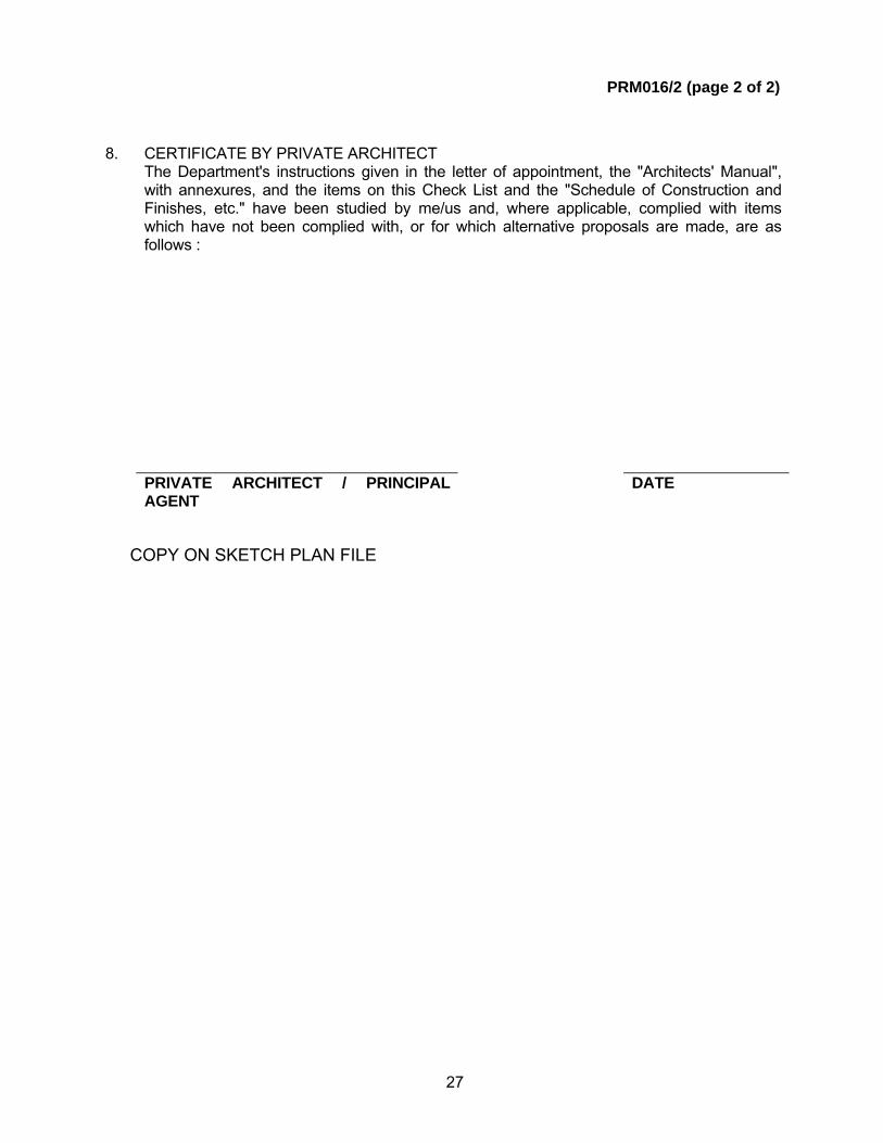
8. CERTIFICATE BY PRIVATE ARCHITECT The Department's instructions given in the letter of appointment, the "Architects' Manual",
with annexures, and the items on this Check List and the "Schedule of Construction and Finishes, etc." have been studied by me/us and, where applicable, complied with items which have not been complied with, or for which alternative proposals are made, are as follows :
PRIVATE ARCHITECT / PRINCIPAL
AGENT DATE
COPY ON SKETCH PLAN FILE
28
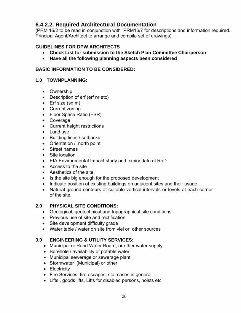
6.4.2.2. Required Architectural Documentation (PRM 16/2 to be read in conjunction with PRM16/7 for descriptions and information required. Principal Agent/Architect to arrange and compile set of drawings)
GUIDELINES FOR DPW ARCHITECTS
• Check List for submission to the Sketch Plan Committee Chairperson • Have all the following planning aspects been considered
BASIC INFORMATION TO BE CONSIDERED: 1.0 TOWNPLANNING:
• Ownership • Description of erf (erf nr etc) • Erf size (sq m) • Current zoning • Floor Space Ratio (FSR) • Coverage • Current height restrictions • Land use • Building lines / setbacks • Orientation / north point • Street names • Site location • EIA Environmental Impact study and expiry date of RoD • Access to the site • Aesthetics of the site • Is the site big enough for the proposed development • Indicate position of existing buildings on adjacent sites and their usage. • Natural ground contours at suitable vertical intervals or levels at each corner
of the site. 2.0 PHYSICAL SITE CONDITIONS:
• Geological, geotechnical and topographical site conditions • Previous use of site and rectification • Site development difficulty grade • Water table / water on site from vlei or other sources
3.0 ENGINEERING & UTILITY SERVICES: • Municipal or Rand Water Board, or other water supply • Borehole / availability of potable water • Municipal sewerage or sewerage plant • Stormwater (Municipal) or other • Electricity • Fire Services, fire escapes, staircases in general • Lifts , goods lifts, Lifts for disabled persons, hoists etc
29
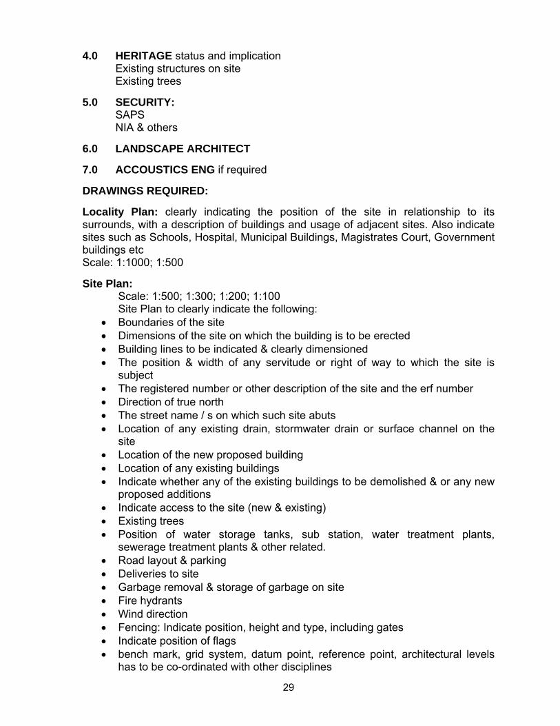
4.0 HERITAGE status and implication Existing structures on site Existing trees
5.0 SECURITY:
SAPS NIA & others
6.0 LANDSCAPE ARCHITECT 7.0 ACCOUSTICS ENG if required DRAWINGS REQUIRED: Locality Plan: clearly indicating the position of the site in relationship to its surrounds, with a description of buildings and usage of adjacent sites. Also indicate sites such as Schools, Hospital, Municipal Buildings, Magistrates Court, Government buildings etc Scale: 1:1000; 1:500 Site Plan:
Scale: 1:500; 1:300; 1:200; 1:100 Site Plan to clearly indicate the following:
• Boundaries of the site • Dimensions of the site on which the building is to be erected • Building lines to be indicated & clearly dimensioned • The position & width of any servitude or right of way to which the site is
subject • The registered number or other description of the site and the erf number • Direction of true north • The street name / s on which such site abuts • Location of any existing drain, stormwater drain or surface channel on the
site • Location of the new proposed building • Location of any existing buildings • Indicate whether any of the existing buildings to be demolished & or any new
proposed additions • Indicate access to the site (new & existing) • Existing trees • Position of water storage tanks, sub station, water treatment plants,
sewerage treatment plants & other related. • Road layout & parking • Deliveries to site • Garbage removal & storage of garbage on site • Fire hydrants • Wind direction • Fencing: Indicate position, height and type, including gates • Indicate position of flags • bench mark, grid system, datum point, reference point, architectural levels
has to be co-ordinated with other disciplines
30
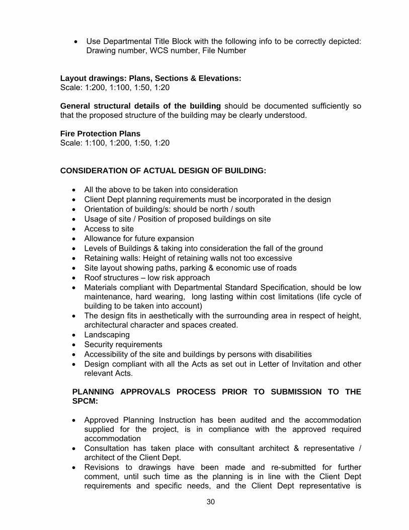
• Use Departmental Title Block with the following info to be correctly depicted: Drawing number, WCS number, File Number
Layout drawings: Plans, Sections & Elevations: Scale: 1:200, 1:100, 1:50, 1:20 General structural details of the building should be documented sufficiently so that the proposed structure of the building may be clearly understood. Fire Protection Plans Scale: 1:100, 1:200, 1:50, 1:20 CONSIDERATION OF ACTUAL DESIGN OF BUILDING:
• All the above to be taken into consideration • Client Dept planning requirements must be incorporated in the design • Orientation of building/s: should be north / south • Usage of site / Position of proposed buildings on site • Access to site • Allowance for future expansion • Levels of Buildings & taking into consideration the fall of the ground • Retaining walls: Height of retaining walls not too excessive • Site layout showing paths, parking & economic use of roads • Roof structures – low risk approach • Materials compliant with Departmental Standard Specification, should be low
maintenance, hard wearing, long lasting within cost limitations (life cycle of building to be taken into account)
• The design fits in aesthetically with the surrounding area in respect of height, architectural character and spaces created.
• Landscaping • Security requirements • Accessibility of the site and buildings by persons with disabilities • Design compliant with all the Acts as set out in Letter of Invitation and other
relevant Acts. PLANNING APPROVALS PROCESS PRIOR TO SUBMISSION TO THE SPCM: • Approved Planning Instruction has been audited and the accommodation
supplied for the project, is in compliance with the approved required accommodation
• Consultation has taken place with consultant architect & representative / architect of the Client Dept.
• Revisions to drawings have been made and re-submitted for further comment, until such time as the planning is in line with the Client Dept requirements and specific needs, and the Client Dept representative is
31
prepared to sign off, and the DPW architect considers that all the other aspects required by DPW have been complied with.
• Consultant architects drawings: locality & site plans; plans; sections & elevations to be issued to DPW professionals i.e. structural, civil, mechanical (air conditioning, ventilation etc), mechanical: (fire, safety & security), electrical, and quantity surveying, for their comments
• All the consultant professional disciplines have consulted with their counterparts at DPW and submitted their Design Reports & drawings.
• After consultation has taken place and once the engineering reports & QS estimates & norms reconciliation are in line with what is required the DPW professionals should indicate that they are satisfied that the work is ready for submission to the SPC .
• Heritage: Establish whether the existing structures are older than 60 years. If there are no Heritage implications then there is no additional approval required from the Heritage Body: SAHRA or the relevant PHRA (Provincial Heritage Resources Agencies).
• These are not necessarily the only aspects of the design to be considered
32
6.4.2 Architectural 6.4.2.3. Cover Page for Distribution to DPW Architect PRM 16/6 PA/Consultant Architect to complete and sign this cover page. Attach to the outside of the set of documentation PROJECT NAME __________________________________________________________ ___________________________________________________________________ WCS NR ____________________ Yes No
1. Set of architectural drawings, see list of drawings on next page.
2. Approved planning instruction is attached
3. A copy of all disciplines’ documentation has been
enclosed. (QS estimate; Mechanical Engineering report & drawings, Mechanical: Fire & Safety report & drawings, structural Engineering report & drawings, Civil Engineering report & drawings, Electrical Engineering report & drawings)
4. The Cost limitation statement/ norms reconciliation
document is attached.
5. The completed PRM16/2 has been attached to this set
________________________ _______________________ NAME PA/Consultant Architect SIGNATURE ____________________________ _____________________________ FIRM DATE For completion by the Principal Agent/Consultant Architect Yes No One set of architectural drawings has been attached ________________________ ______________________ NAME SIGNATURE ____________________________ _________________________DESIGNATION DATE For completion by the: DPW Architect For Sketch Plan purposes the recommendation to the SPC Chairperson is : ACCEPT/NOT ACCEPT the Sketch Plan design submitted. ________________________ ______________________ NAME SIGNATURE ____________________________ _________________________DESIGNATION DATE COPY ON SKETCH PLAN FILE
33
6.4.3. Civil Engineering 6.4.3.1. Cover Page for Distribution to DPW Civil Engineer PRM 16/7 This form must be completed and signed by the Consultant Civil Engineer. Attach form to the outside of the set of documentation for distribution purposes. PROJECT NAME ___________________________________________________ ___________________________________________________________________ WCS NR ____________________
Yes No 1. The preliminary design has been completed in terms of
conditions 2. Preliminary design report has been attached, see
attached guideline and also refer to the engineer’s manual
3. The design has been coordinated with architect. Note:
see engineer’s manual for preliminary design documents
4. The departmental engineer has been consulted
5. The departmental engineer’s comments has been incorporated into the design, if not, state reasons below:
6. Dolomite Status Certificate is attached.
Comments: __________________________________________________________________________ NAME SIGNATURE ___________________________________ _______________________ FIRM DATE For completion by the Principal Agent/Architect /Engineer Yes No One set of architectural drawings has been attached ________________________ ______________________ NAME SIGNATURE ____________________________ _________________________DESIGNATION DATE For completion by the: DPW Civil Engineer For Sketch Plan purposes the recommendation to the SPC Chairperson is : ACCEPT/NOT ACCEPT the Sketch Plan design submitted. _______________________ ______________________ NAME SIGNATURE ____________________________ _________________________DESIGNATION DATE COPY ON SKETCH PLAN FILE
34
6.4.3.2. Documentation Required for Civil Engineering SKETCH PLAN (PRELIMINARY DESIGN) STAGE - (CIVIL ENGINEERING) General Comment The Department of Public Works has a large and diverse property portfolio. Various Departmental Guidelines have been prepared to assist Professional Consultants in the design and documentation of DPW Projects. They provide direction and guidance on DPW’s requirements and enable Consultants to efficiently translate them into acceptable design solutions. The Guidelines are not intended to replace the level of initiative, competence and care as expected of consultants in the performance of their duties. Consultants are encouraged to carefully consider the merits of the Design Guidelines in the context of the needs of individual projects. If a Consultant considers a guideline not to be appropriate and that a more suitable solution is available, proposals to this effect should be raised for consideration by the Department. In the absence of express written approval for a deviation from Departmental guidelines, the Department will assume that the requirements contained in the various Design Guidelines have been fully addressed and incorporated in the proposed Design Solution and Specifications. Design calculations and investigations should be performed through all stages in an orderly, logical way. They should not only allow the design engineer to arrive at conclusions sufficient to lead to the preparation of detailed drawings, but their final form should reflect neat and systematic thought processes. At any time in the future someone wanting to check back on the original design should be able to find out what the design engineer was trying to achieve and what design standards he used. The engineer must take particular care in presenting the work connected with his design to ensure that:
• The design processes themselves are orderly, legible and logical so that the engineer charged with the checking should be able to follow them with ease;
• The technical and academic quality is acceptable; and
• Adequate draughting standards are complied with. The Preliminary Design Report (PDR) gives the designer the opportunity to set out the design considerations and obtain approval for proposed deviations from Departmental standards. Where various options exist to arrive at a suitable design solution, the Department can select the preferred configuration based on information presented in the PDR. To enable the Departmental Civil Engineer to endorse the civil design at Sketch Plan Stage, the designer must have submitted a PDR documenting all facets of the design, to the Department. The following section proposes a checklist that should be completed by the Project Manager and Professional Consultant to ensure that the Departmental Civil Engineer has sufficient project detail to enable him to check the design proposal:
35
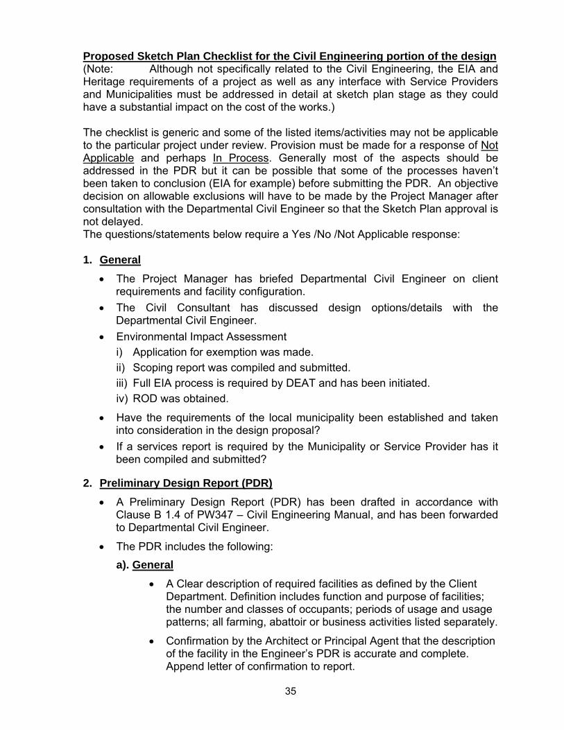
Proposed Sketch Plan Checklist for the Civil Engineering portion of the design (Note: Although not specifically related to the Civil Engineering, the EIA and
Heritage requirements of a project as well as any interface with Service Providers and Municipalities must be addressed in detail at sketch plan stage as they could have a substantial impact on the cost of the works.) The checklist is generic and some of the listed items/activities may not be applicable to the particular project under review. Provision must be made for a response of Not Applicable and perhaps In Process. Generally most of the aspects should be addressed in the PDR but it can be possible that some of the processes haven’t been taken to conclusion (EIA for example) before submitting the PDR. An objective decision on allowable exclusions will have to be made by the Project Manager after consultation with the Departmental Civil Engineer so that the Sketch Plan approval is not delayed. The questions/statements below require a Yes /No /Not Applicable response: 1. General
• The Project Manager has briefed Departmental Civil Engineer on client requirements and facility configuration.
• The Civil Consultant has discussed design options/details with the Departmental Civil Engineer.
• Environmental Impact Assessment i) Application for exemption was made. ii) Scoping report was compiled and submitted. iii) Full EIA process is required by DEAT and has been initiated. iv) ROD was obtained.
• Have the requirements of the local municipality been established and taken into consideration in the design proposal?
• If a services report is required by the Municipality or Service Provider has it been compiled and submitted?
2. Preliminary Design Report (PDR) • A Preliminary Design Report (PDR) has been drafted in accordance with
Clause B 1.4 of PW347 – Civil Engineering Manual, and has been forwarded to Departmental Civil Engineer.
• The PDR includes the following: a). General
• A Clear description of required facilities as defined by the Client Department. Definition includes function and purpose of facilities; the number and classes of occupants; periods of usage and usage patterns; all farming, abattoir or business activities listed separately.
• Confirmation by the Architect or Principal Agent that the description of the facility in the Engineer’s PDR is accurate and complete. Append letter of confirmation to report.
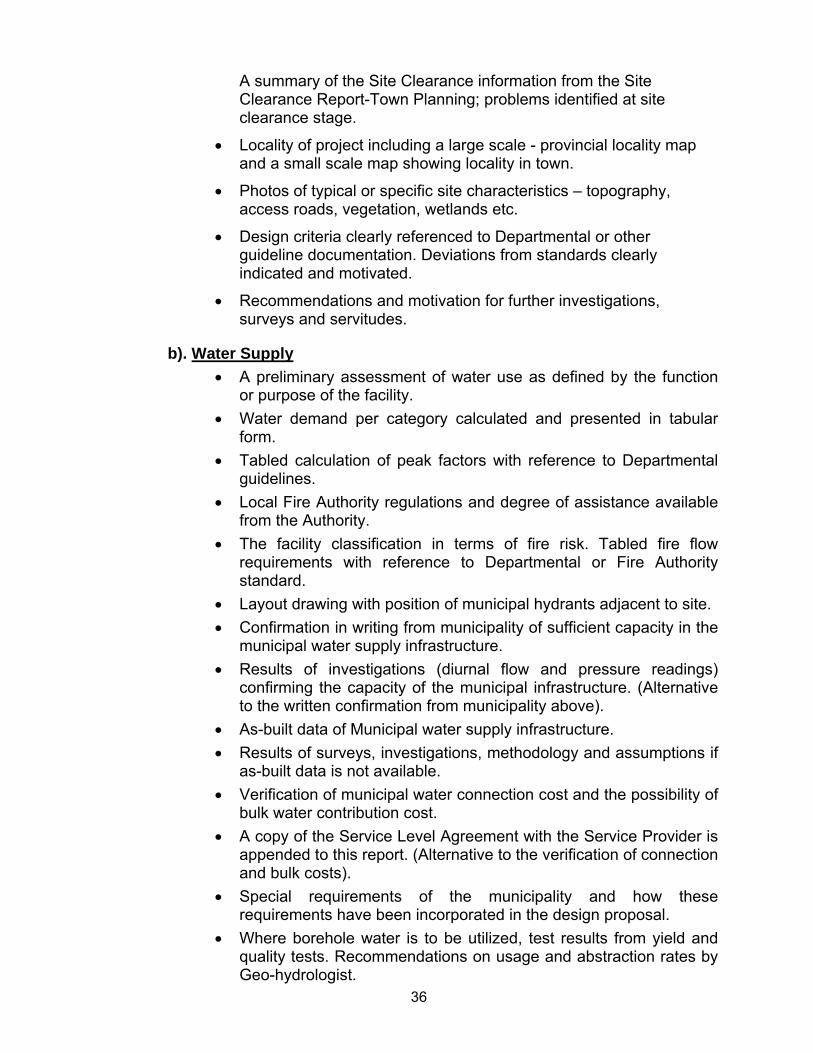
36
A summary of the Site Clearance information from the Site Clearance Report-Town Planning; problems identified at site clearance stage.
• Locality of project including a large scale - provincial locality map and a small scale map showing locality in town.
• Photos of typical or specific site characteristics – topography, access roads, vegetation, wetlands etc.
• Design criteria clearly referenced to Departmental or other guideline documentation. Deviations from standards clearly indicated and motivated.
• Recommendations and motivation for further investigations, surveys and servitudes.
b). Water Supply • A preliminary assessment of water use as defined by the function
or purpose of the facility. • Water demand per category calculated and presented in tabular
form. • Tabled calculation of peak factors with reference to Departmental
guidelines. • Local Fire Authority regulations and degree of assistance available
from the Authority. • The facility classification in terms of fire risk. Tabled fire flow
requirements with reference to Departmental or Fire Authority standard.
• Layout drawing with position of municipal hydrants adjacent to site. • Confirmation in writing from municipality of sufficient capacity in the
municipal water supply infrastructure. • Results of investigations (diurnal flow and pressure readings)
confirming the capacity of the municipal infrastructure. (Alternative to the written confirmation from municipality above).
• As-built data of Municipal water supply infrastructure. • Results of surveys, investigations, methodology and assumptions if
as-built data is not available. • Verification of municipal water connection cost and the possibility of
bulk water contribution cost. • A copy of the Service Level Agreement with the Service Provider is
appended to this report. (Alternative to the verification of connection and bulk costs).
• Special requirements of the municipality and how these requirements have been incorporated in the design proposal.
• Where borehole water is to be utilized, test results from yield and quality tests. Recommendations on usage and abstraction rates by Geo-hydrologist.
37
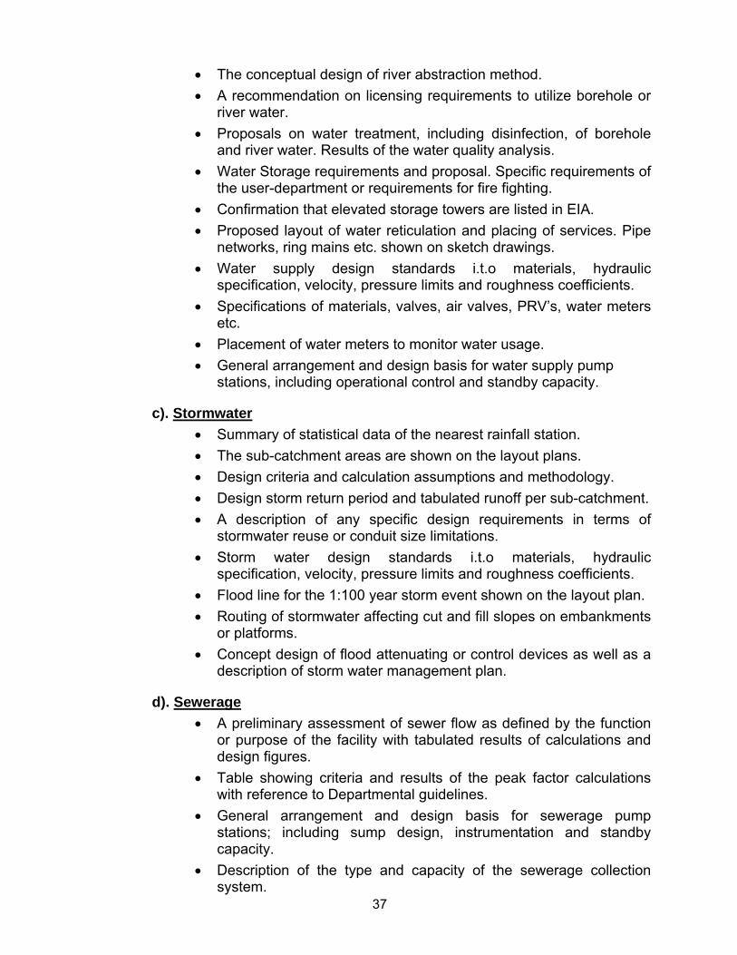
• The conceptual design of river abstraction method. • A recommendation on licensing requirements to utilize borehole or
river water. • Proposals on water treatment, including disinfection, of borehole
and river water. Results of the water quality analysis. • Water Storage requirements and proposal. Specific requirements of
the user-department or requirements for fire fighting. • Confirmation that elevated storage towers are listed in EIA. • Proposed layout of water reticulation and placing of services. Pipe
networks, ring mains etc. shown on sketch drawings. • Water supply design standards i.t.o materials, hydraulic
specification, velocity, pressure limits and roughness coefficients. • Specifications of materials, valves, air valves, PRV’s, water meters
etc. • Placement of water meters to monitor water usage. • General arrangement and design basis for water supply pump
stations, including operational control and standby capacity.
c). Stormwater • Summary of statistical data of the nearest rainfall station. • The sub-catchment areas are shown on the layout plans. • Design criteria and calculation assumptions and methodology. • Design storm return period and tabulated runoff per sub-catchment. • A description of any specific design requirements in terms of
stormwater reuse or conduit size limitations. • Storm water design standards i.t.o materials, hydraulic
specification, velocity, pressure limits and roughness coefficients. • Flood line for the 1:100 year storm event shown on the layout plan. • Routing of stormwater affecting cut and fill slopes on embankments
or platforms. • Concept design of flood attenuating or control devices as well as a
description of storm water management plan.
d). Sewerage • A preliminary assessment of sewer flow as defined by the function
or purpose of the facility with tabulated results of calculations and design figures.
• Table showing criteria and results of the peak factor calculations with reference to Departmental guidelines.
• General arrangement and design basis for sewerage pump stations; including sump design, instrumentation and standby capacity.
• Description of the type and capacity of the sewerage collection system.
38
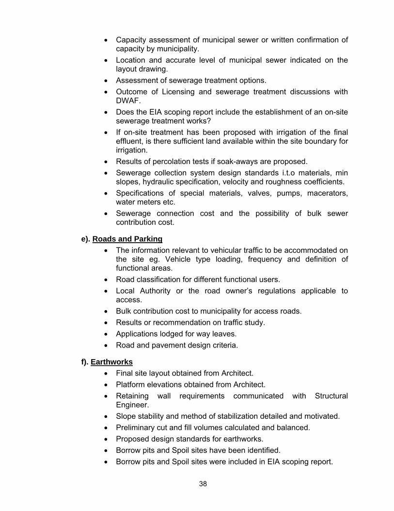
• Capacity assessment of municipal sewer or written confirmation of capacity by municipality.
• Location and accurate level of municipal sewer indicated on the layout drawing.
• Assessment of sewerage treatment options. • Outcome of Licensing and sewerage treatment discussions with
DWAF. • Does the EIA scoping report include the establishment of an on-site
sewerage treatment works? • If on-site treatment has been proposed with irrigation of the final
effluent, is there sufficient land available within the site boundary for irrigation.
• Results of percolation tests if soak-aways are proposed. • Sewerage collection system design standards i.t.o materials, min
slopes, hydraulic specification, velocity and roughness coefficients. • Specifications of special materials, valves, pumps, macerators,
water meters etc. • Sewerage connection cost and the possibility of bulk sewer
contribution cost.
e). Roads and Parking • The information relevant to vehicular traffic to be accommodated on
the site eg. Vehicle type loading, frequency and definition of functional areas.
• Road classification for different functional users. • Local Authority or the road owner’s regulations applicable to
access. • Bulk contribution cost to municipality for access roads. • Results or recommendation on traffic study. • Applications lodged for way leaves. • Road and pavement design criteria.
f). Earthworks • Final site layout obtained from Architect. • Platform elevations obtained from Architect. • Retaining wall requirements communicated with Structural
Engineer. • Slope stability and method of stabilization detailed and motivated. • Preliminary cut and fill volumes calculated and balanced. • Proposed design standards for earthworks. • Borrow pits and Spoil sites have been identified. • Borrow pits and Spoil sites were included in EIA scoping report.
39
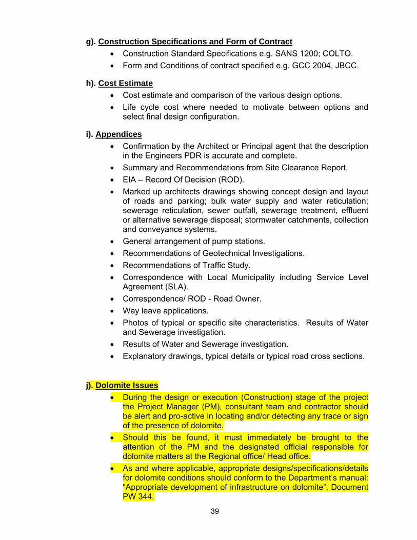
g). Construction Specifications and Form of Contract • Construction Standard Specifications e.g. SANS 1200; COLTO. • Form and Conditions of contract specified e.g. GCC 2004, JBCC.
h). Cost Estimate • Cost estimate and comparison of the various design options. • Life cycle cost where needed to motivate between options and
select final design configuration.
i). Appendices • Confirmation by the Architect or Principal agent that the description
in the Engineers PDR is accurate and complete. • Summary and Recommendations from Site Clearance Report. • EIA – Record Of Decision (ROD). • Marked up architects drawings showing concept design and layout
of roads and parking; bulk water supply and water reticulation; sewerage reticulation, sewer outfall, sewerage treatment, effluent or alternative sewerage disposal; stormwater catchments, collection and conveyance systems.
• General arrangement of pump stations. • Recommendations of Geotechnical Investigations. • Recommendations of Traffic Study. • Correspondence with Local Municipality including Service Level
Agreement (SLA). • Correspondence/ ROD - Road Owner. • Way leave applications. • Photos of typical or specific site characteristics. Results of Water
and Sewerage investigation. • Results of Water and Sewerage investigation. • Explanatory drawings, typical details or typical road cross sections.
j). Dolomite Issues • During the design or execution (Construction) stage of the project
the Project Manager (PM), consultant team and contractor should be alert and pro-active in locating and/or detecting any trace or sign of the presence of dolomite.
• Should this be found, it must immediately be brought to the attention of the PM and the designated official responsible for dolomite matters at the Regional office/ Head office.
• As and where applicable, appropriate designs/specifications/details for dolomite conditions should conform to the Department’s manual: “Appropriate development of infrastructure on dolomite”, Document PW 344.

40
• Should there be any uncertainty about the presence of dolomite and/or unscheduled ground movement event, then such enquiries should be referred to the Directorate: Civil & Structural Engineering at Head Office for further investigation and subsequent certification.
41
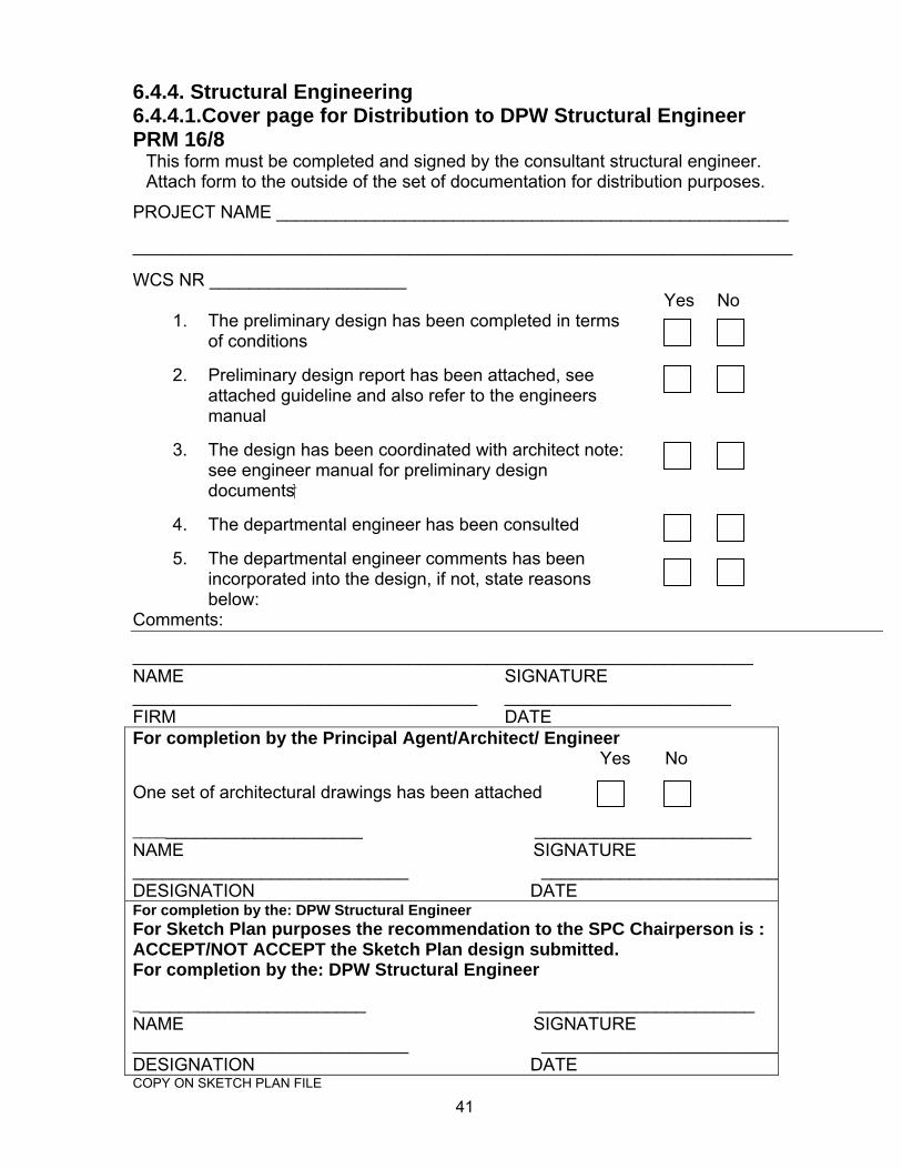
6.4.4. Structural Engineering 6.4.4.1.Cover page for Distribution to DPW Structural Engineer PRM 16/8
This form must be completed and signed by the consultant structural engineer. Attach form to the outside of the set of documentation for distribution purposes.
PROJECT NAME ____________________________________________________ ___________________________________________________________________ WCS NR ____________________
Yes No 1. The preliminary design has been completed in terms
of conditions 2. Preliminary design report has been attached, see
attached guideline and also refer to the engineers manual
3. The design has been coordinated with architect note:
see engineer manual for preliminary design documents
4. The departmental engineer has been consulted
5. The departmental engineer comments has been
incorporated into the design, if not, state reasons below:
Comments: _______________________________________________________________ NAME SIGNATURE ___________________________________ _______________________ FIRM DATE For completion by the Principal Agent/Architect/ Engineer Yes No One set of architectural drawings has been attached ________________________ ______________________ NAME SIGNATURE ____________________________ _________________________DESIGNATION DATE For completion by the: DPW Structural Engineer For Sketch Plan purposes the recommendation to the SPC Chairperson is : ACCEPT/NOT ACCEPT the Sketch Plan design submitted. For completion by the: DPW Structural Engineer ________________________ ______________________ NAME SIGNATURE ____________________________ _________________________DESIGNATION DATE COPY ON SKETCH PLAN FILE
42
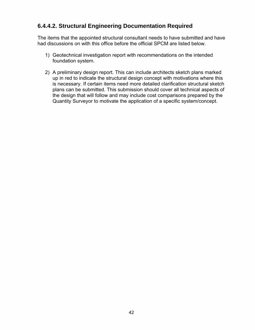
6.4.4.2. Structural Engineering Documentation Required The items that the appointed structural consultant needs to have submitted and have had discussions on with this office before the official SPCM are listed below.
1) Geotechnical investigation report with recommendations on the intended foundation system.
2) A preliminary design report. This can include architects sketch plans marked
up in red to indicate the structural design concept with motivations where this is necessary. If certain items need more detailed clarification structural sketch plans can be submitted. This submission should cover all technical aspects of the design that will follow and may include cost comparisons prepared by the Quantity Surveyor to motivate the application of a specific system/concept.
43
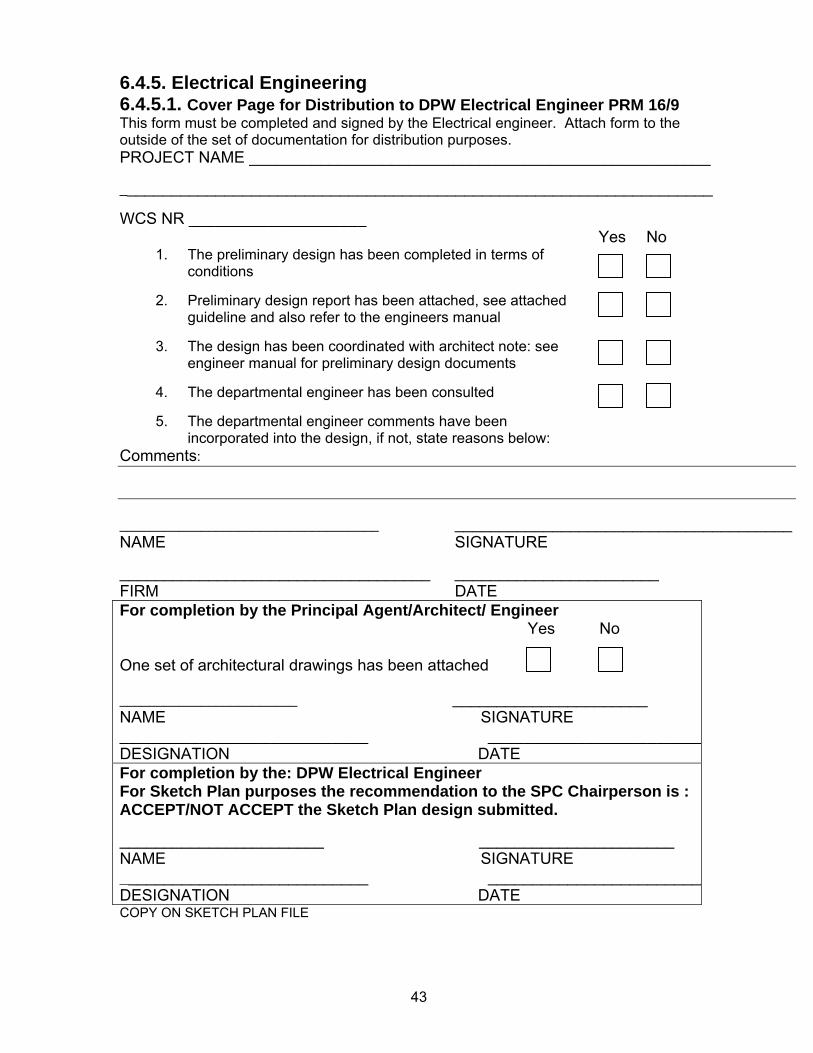
6.4.5. Electrical Engineering 6.4.5.1. Cover Page for Distribution to DPW Electrical Engineer PRM 16/9 This form must be completed and signed by the Electrical engineer. Attach form to the outside of the set of documentation for distribution purposes. PROJECT NAME ____________________________________________________ ___________________________________________________________________ WCS NR ____________________
Yes No 1. The preliminary design has been completed in terms of
conditions
2. Preliminary design report has been attached, see attached guideline and also refer to the engineers manual
3. The design has been coordinated with architect note: see
engineer manual for preliminary design documents
4. The departmental engineer has been consulted
5. The departmental engineer comments have been incorporated into the design, if not, state reasons below:
Comments: ___________________________________ ______________________________________ NAME SIGNATURE ___________________________________ _______________________ FIRM DATE For completion by the Principal Agent/Architect/ Engineer Yes No One set of architectural drawings has been attached ________________________ ______________________ NAME SIGNATURE ____________________________ _________________________DESIGNATION DATE For completion by the: DPW Electrical Engineer For Sketch Plan purposes the recommendation to the SPC Chairperson is : ACCEPT/NOT ACCEPT the Sketch Plan design submitted. _______________________ ______________________ NAME SIGNATURE ____________________________ _________________________DESIGNATION DATE COPY ON SKETCH PLAN FILE
44
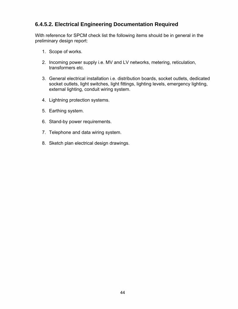
6.4.5.2. Electrical Engineering Documentation Required With reference for SPCM check list the following items should be in general in the preliminary design report:
1. Scope of works.
2. Incoming power supply i.e. MV and LV networks, metering, reticulation, transformers etc.
3. General electrical installation i.e. distribution boards, socket outlets, dedicated socket outlets, light switches, light fittings, lighting levels, emergency lighting, external lighting, conduit wiring system.
4. Lightning protection systems.
5. Earthing system.
6. Stand-by power requirements.
7. Telephone and data wiring system.
8. Sketch plan electrical design drawings.
45
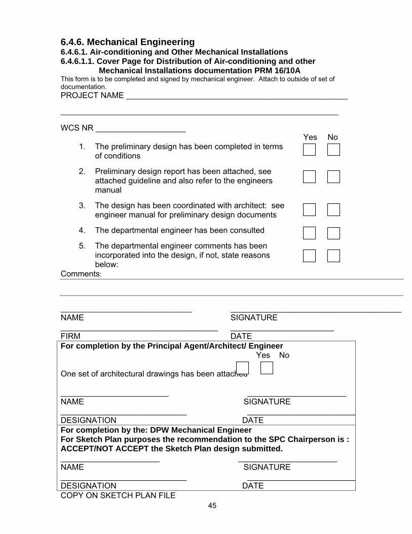
6.4.6. Mechanical Engineering 6.4.6.1. Air-conditioning and Other Mechanical Installations 6.4.6.1.1. Cover Page for Distribution of Air-conditioning and other Mechanical Installations documentation PRM 16/10A This form is to be completed and signed by mechanical engineer. Attach to outside of set of documentation. PROJECT NAME ___________________________________________________________ __________________________________________________________________________ WCS NR ____________________
Yes No 1. The preliminary design has been completed in terms
of conditions
2. Preliminary design report has been attached, see attached guideline and also refer to the engineers manual
3. The design has been coordinated with architect: see
engineer manual for preliminary design documents
4. The departmental engineer has been consulted
5. The departmental engineer comments has been incorporated into the design, if not, state reasons below:
Comments: ___________________________________ ______________________________________ NAME SIGNATURE ___________________________________ _______________________ FIRM DATE For completion by the Principal Agent/Architect/ Engineer Yes No One set of architectural drawings has been attached ________________________ ______________________ NAME SIGNATURE ____________________________ _________________________DESIGNATION DATE For completion by the: DPW Mechanical Engineer For Sketch Plan purposes the recommendation to the SPC Chairperson is : ACCEPT/NOT ACCEPT the Sketch Plan design submitted. ______________________ ______________________ NAME SIGNATURE ____________________________ _________________________DESIGNATION DATE COPY ON SKETCH PLAN FILE
46
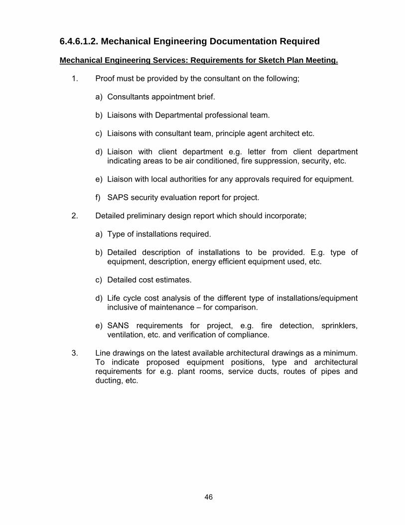
6.4.6.1.2. Mechanical Engineering Documentation Required Mechanical Engineering Services: Requirements for Sketch Plan Meeting.
1. Proof must be provided by the consultant on the following;
a) Consultants appointment brief. b) Liaisons with Departmental professional team. c) Liaisons with consultant team, principle agent architect etc. d) Liaison with client department e.g. letter from client department
indicating areas to be air conditioned, fire suppression, security, etc. e) Liaison with local authorities for any approvals required for equipment. f) SAPS security evaluation report for project.
2. Detailed preliminary design report which should incorporate;
a) Type of installations required. b) Detailed description of installations to be provided. E.g. type of
equipment, description, energy efficient equipment used, etc.
c) Detailed cost estimates.
d) Life cycle cost analysis of the different type of installations/equipment inclusive of maintenance – for comparison.
e) SANS requirements for project, e.g. fire detection, sprinklers,
ventilation, etc. and verification of compliance.
3. Line drawings on the latest available architectural drawings as a minimum. To indicate proposed equipment positions, type and architectural requirements for e.g. plant rooms, service ducts, routes of pipes and ducting, etc.
47
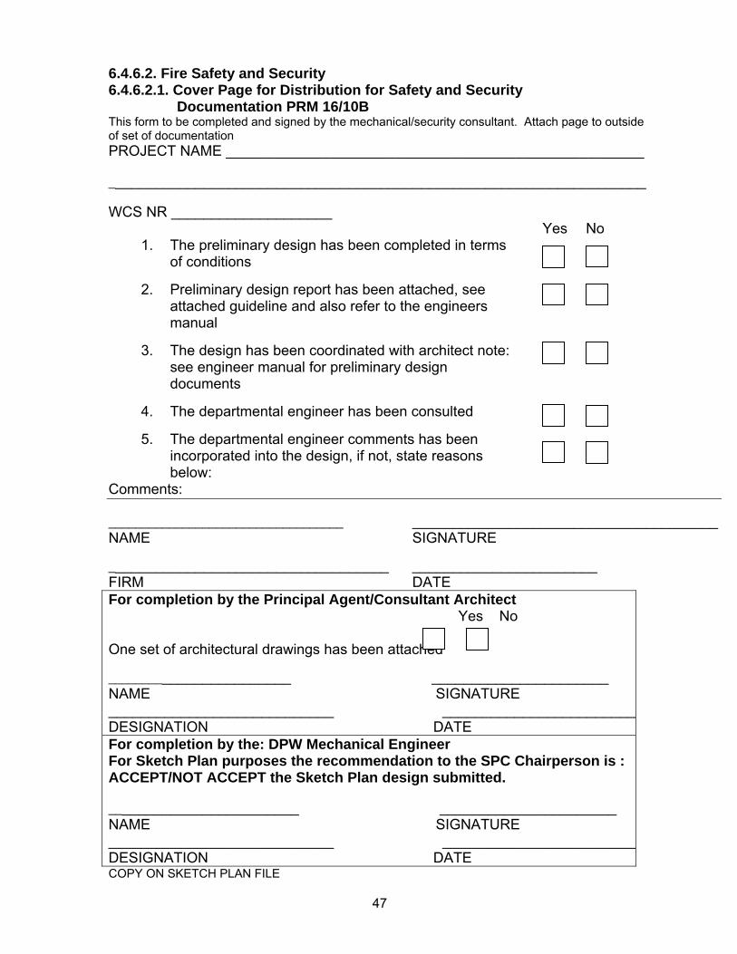
6.4.6.2. Fire Safety and Security 6.4.6.2.1. Cover Page for Distribution for Safety and Security Documentation PRM 16/10B This form to be completed and signed by the mechanical/security consultant. Attach page to outside of set of documentation PROJECT NAME ____________________________________________________ ___________________________________________________________________ WCS NR ____________________
Yes No 1. The preliminary design has been completed in terms
of conditions
2. Preliminary design report has been attached, see attached guideline and also refer to the engineers manual
3. The design has been coordinated with architect note:
see engineer manual for preliminary design documents
4. The departmental engineer has been consulted
5. The departmental engineer comments has been
incorporated into the design, if not, state reasons below:
Comments: ___________________________________ ______________________________________ NAME SIGNATURE ___________________________________ _______________________ FIRM DATE For completion by the Principal Agent/Consultant Architect Yes No One set of architectural drawings has been attached ________________________ ______________________ NAME SIGNATURE ____________________________ _________________________DESIGNATION DATE For completion by the: DPW Mechanical Engineer For Sketch Plan purposes the recommendation to the SPC Chairperson is : ACCEPT/NOT ACCEPT the Sketch Plan design submitted. ________________________ ______________________ NAME SIGNATURE ____________________________ _________________________DESIGNATION DATE COPY ON SKETCH PLAN FILE
48
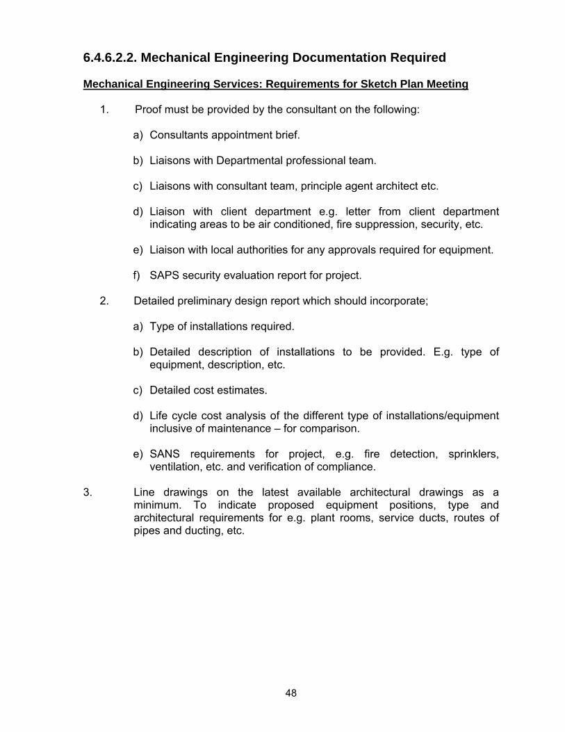
6.4.6.2.2. Mechanical Engineering Documentation Required Mechanical Engineering Services: Requirements for Sketch Plan Meeting
1. Proof must be provided by the consultant on the following:
a) Consultants appointment brief. b) Liaisons with Departmental professional team. c) Liaisons with consultant team, principle agent architect etc. d) Liaison with client department e.g. letter from client department
indicating areas to be air conditioned, fire suppression, security, etc. e) Liaison with local authorities for any approvals required for equipment. f) SAPS security evaluation report for project.
2. Detailed preliminary design report which should incorporate;
a) Type of installations required. b) Detailed description of installations to be provided. E.g. type of
equipment, description, etc.
c) Detailed cost estimates.
d) Life cycle cost analysis of the different type of installations/equipment inclusive of maintenance – for comparison.
e) SANS requirements for project, e.g. fire detection, sprinklers,
ventilation, etc. and verification of compliance. 3. Line drawings on the latest available architectural drawings as a
minimum. To indicate proposed equipment positions, type and architectural requirements for e.g. plant rooms, service ducts, routes of pipes and ducting, etc.
49
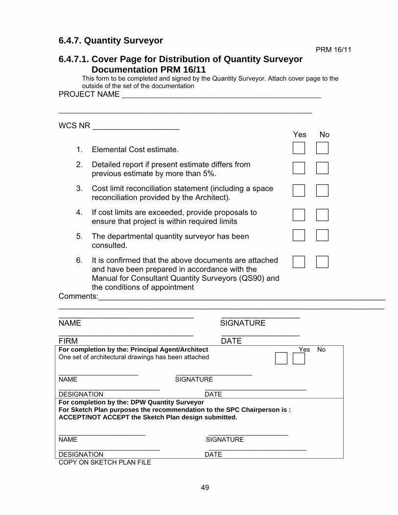
6.4.7. Quantity Surveyor PRM 16/11
6.4.7.1. Cover Page for Distribution of Quantity Surveyor Documentation PRM 16/11
This form to be completed and signed by the Quantity Surveyor. Attach cover page to the outside of the set of the documentation
PROJECT NAME _______________________________________________________ ______________________________________________________________________ WCS NR ____________________ Yes No
1. Elemental Cost estimate.
2. Detailed report if present estimate differs from previous estimate by more than 5%.
3. Cost limit reconciliation statement (including a space
reconciliation provided by the Architect).
4. If cost limits are exceeded, provide proposals to ensure that project is within required limits
5. The departmental quantity surveyor has been
consulted.
6. It is confirmed that the above documents are attached and have been prepared in accordance with the Manual for Consultant Quantity Surveyors (QS90) and the conditions of appointment
Comments:__________________________________________________________________ ___________________________________________________________________________ _______________________________ __________________ NAME SIGNATURE _______________________________ __________________ FIRM DATE For completion by the: Principal Agent/Architect Yes No One set of architectural drawings has been attached ______________________ _____________________ NAME SIGNATURE ____________________________ ____________________________ DESIGNATION DATE For completion by the: DPW Quantity Surveyor For Sketch Plan purposes the recommendation to the SPC Chairperson is : ACCEPT/NOT ACCEPT the Sketch Plan design submitted. ________________________ ______________________ NAME SIGNATURE ____________________________ ___________________________ DESIGNATION DATE COPY ON SKETCH PLAN FILE
50
6.4.8. Town Planning PRM 16/12
6.4.8.1. Cover Page for Distribution of Town Planning Documentation PRM 16/12
This form to be completed and signed by the Consultant Town Planner/PA/ Consultant Architect. Attach cover page to the outside of the set of the documentation
PROJECT NAME: ____________________________________________________ WCS NR ____________________ Yes No
1. Site layout, showing site boundaries, parking, access 2. Title deed, Surveyor General diagrams, servitudes
3. Geotechnical study conducted
4. Mapping of site (contours, structures, aerial photo)
5. Position of sewage treatment solution (piped, other)
6. Position of water supply solution (piped, bore hole)
7. Position of electrical supply point(s)
8. Environmental Authorisation (EIA) if applicable
9. Existing land use rights (zoning) information
I hereby confirm that I complied with requirements of the Site Clearance Certificate Comments: ___________________________________ _____________________________ NAME TOWN PLANNER/PA/CONSULTANT ARCHITECT SIGNATURE ___________________________________ _______________________ FIRM DATE For completion by the: Principal Agent/Architect Yes No One set of architectural drawings has been attached ______________________ _____________________ NAME SIGNATURE ____________________________ ____________________________ DESIGNATION DATE For completion by the: DPW Town Planner For Sketch Plan purposes the recommendation to the SPC Chairperson is : ACCEPT/NOT ACCEPT the Sketch Plan design submitted. ________________________ ______________________ NAME SIGNATURE ____________________________ ___________________________ DIRECTOR: TOWN PLANNING DATE COPY ON SKETCH PLAN FILE
51
6.4.9. Other Consultants for information of DPW Architect PRM 16/13
6.4.9.1. Cover Page for Distribution of Other Consultants PRM 16/13 This form to be completed and signed by the relevant Consultant . Attach cover page to the outside of the set of the documentation
PROJECT NAME ___________________________________________________________ ____________________________________________________________________ WCS NR ____________________ Yes No
1. Scope of works 2. List attached documentation.
3. Note interaction with DPW officials.
4. All documentation is in line with appointment
conditions and legislation.
5. ___________________________________________
6. ___________________________________________
7. ___________________________________________
8. ___________________________________________
9. ___________________________________________ Comments: ___________________________________ ______________________________________ NAME OTHER CONSULTANT SIGNATURE ___________________________________ _______________________ FIRM DATE For completion by the: Principal Agent/Architect Yes No One set of architectural drawings has been attached ______________________ _____________________ NAME SIGNATURE ____________________________ ____________________________ DESIGNATION DATE For completion by the: DPW For Sketch Plan purposes the recommendation to the SPC Chairperson is : ACCEPT/NOT ACCEPT the Sketch Plan design submitted. ________________________ ______________________ NAME SIGNATURE ____________________________ ___________________________ DESIGNATION DATE COPY ON SKETCH PLAN FILE
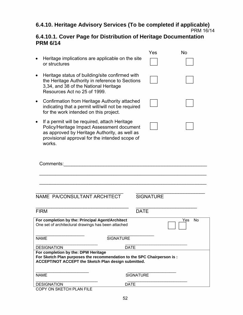
52
6.4.10. Heritage Advisory Services (To be completed if applicable) PRM 16/14
6.4.10.1. Cover Page for Distribution of Heritage Documentation PRM 6/14
Yes No • Heritage implications are applicable on the site
or structures
• Heritage status of building/site confirmed with the Heritage Authority in reference to Sections 3,34, and 38 of the National Heritage Resources Act no 25 of 1999.
• Confirmation from Heritage Authority attached indicating that a permit will/will not be required for the work intended on this project.
• If a permit will be required, attach Heritage Policy/Heritage Impact Assessment document as approved by Heritage Authority, as well as provisional approval for the intended scope of works.
Comments:______________________________________________________ _______________________________________________________________ _______________________________________________________________
_________________________________ __________________________ NAME PA/CONSULTANT ARCHITECT SIGNATURE ___________________________________ _______________________ FIRM DATE For completion by the: Principal Agent/Architect Yes No One set of architectural drawings has been attached ______________________ _____________________ NAME SIGNATURE ____________________________ ____________________________ DESIGNATION DATE For completion by the: DPW Heritage For Sketch Plan purposes the recommendation to the SPC Chairperson is : ACCEPT/NOT ACCEPT the Sketch Plan design submitted. ________________________ ______________________ NAME SIGNATURE ____________________________ ___________________________ DESIGNATION DATE COPY ON SKETCH PLAN FILE
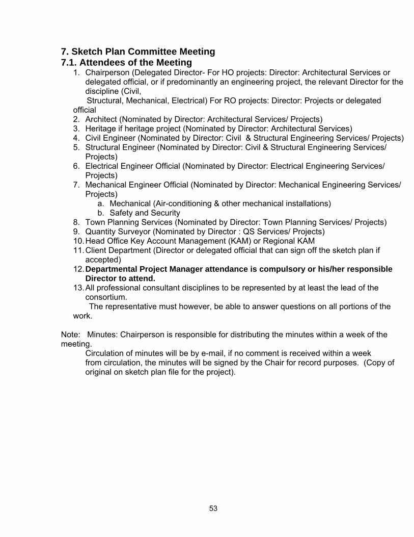
53
7. Sketch Plan Committee Meeting 7.1. Attendees of the Meeting
1. Chairperson (Delegated Director- For HO projects: Director: Architectural Services or delegated official, or if predominantly an engineering project, the relevant Director for the discipline (Civil,
Structural, Mechanical, Electrical) For RO projects: Director: Projects or delegated official 2. Architect (Nominated by Director: Architectural Services/ Projects) 3. Heritage if heritage project (Nominated by Director: Architectural Services) 4. Civil Engineer (Nominated by Director: Civil & Structural Engineering Services/ Projects) 5. Structural Engineer (Nominated by Director: Civil & Structural Engineering Services/
Projects) 6. Electrical Engineer Official (Nominated by Director: Electrical Engineering Services/
Projects) 7. Mechanical Engineer Official (Nominated by Director: Mechanical Engineering Services/
Projects) a. Mechanical (Air-conditioning & other mechanical installations) b. Safety and Security
8. Town Planning Services (Nominated by Director: Town Planning Services/ Projects) 9. Quantity Surveyor (Nominated by Director : QS Services/ Projects) 10. Head Office Key Account Management (KAM) or Regional KAM 11. Client Department (Director or delegated official that can sign off the sketch plan if
accepted) 12. Departmental Project Manager attendance is compulsory or his/her responsible
Director to attend. 13. All professional consultant disciplines to be represented by at least the lead of the
consortium. The representative must however, be able to answer questions on all portions of the work.
Note: Minutes: Chairperson is responsible for distributing the minutes within a week of the meeting.
Circulation of minutes will be by e-mail, if no comment is received within a week from circulation, the minutes will be signed by the Chair for record purposes. (Copy of original on sketch plan file for the project).
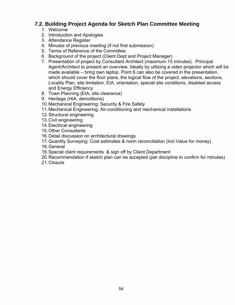
54
7.2. Building Project Agenda for Sketch Plan Committee Meeting 1. Welcome 2. Introduction and Apologies 3. Attendance Register 4. Minutes of previous meeting (if not first submission) 5. Terms of Reference of the Committee 6. Background of the project (Client Dept and Project Manager) 7. Presentation of project by Consultant Architect (maximum 15 minutes). Principal
Agent/Architect to present an overview. Ideally by utilizing a video projector which will be made available – bring own laptop. Point 6 can also be covered in the presentation, which should cover the floor plans, the logical flow of the project, elevations, sections, Locality Plan, site limitation, EIA, orientation, special site conditions, disabled access and Energy Efficiency
8. Town Planning (EIA, site clearance) 9. Heritage (HIA, demolitions) 10. Mechanical Engineering: Security & Fire Safety 11. Mechanical Engineering: Air-conditioning and mechanical installations 12. Structural engineering 13. Civil engineering 14. Electrical engineering 15. Other Consultants 16. Detail discussion on architectural drawings 17. Quantity Surveying: Cost estimates & norm reconciliation (incl Value for money) 18. General 19. Special client requirements & sign off by Client Department 20. Recommendation if sketch plan can be accepted (per discipline to confirm for minutes) 21. Closure
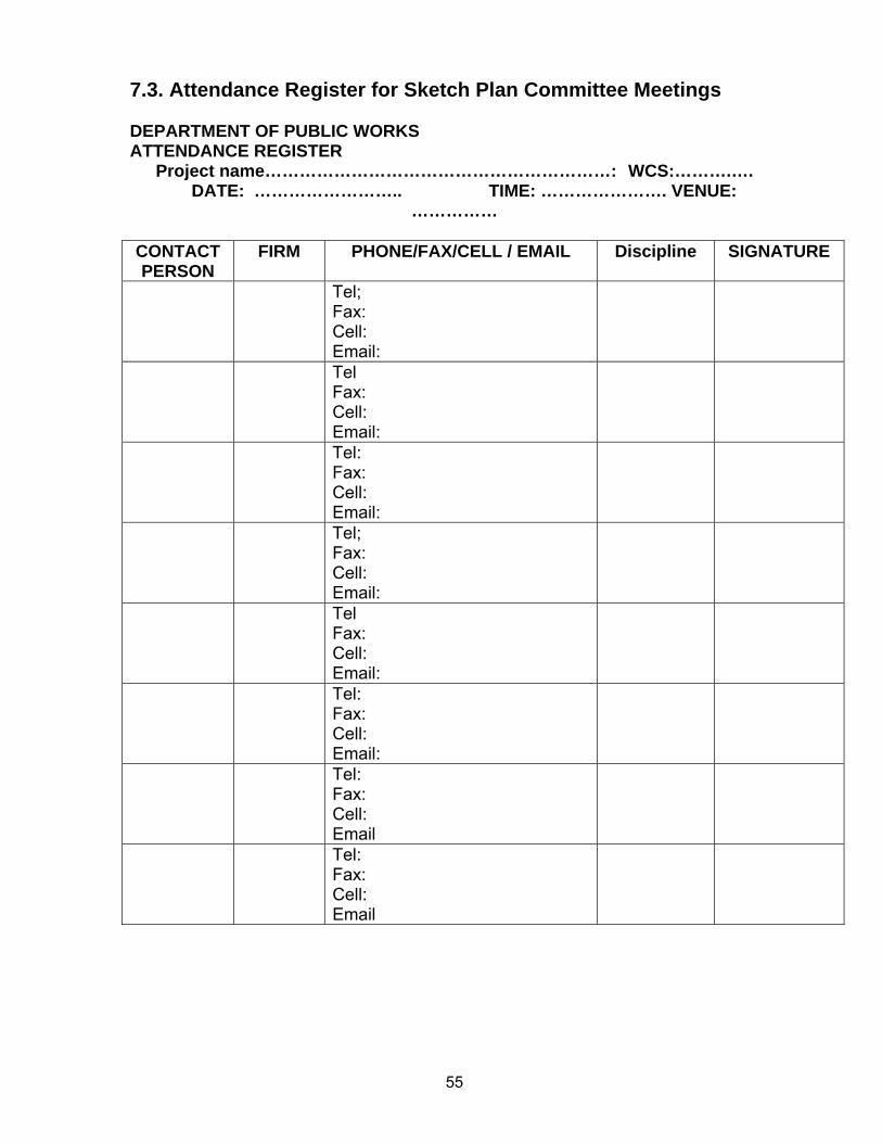
55
7.3. Attendance Register for Sketch Plan Committee Meetings DEPARTMENT OF PUBLIC WORKS ATTENDANCE REGISTER
Project name……………………………………………………: WCS:……….…. DATE: …………………….. TIME: …………………. VENUE:
…………… CONTACT PERSON
FIRM PHONE/FAX/CELL / EMAIL Discipline SIGNATURE
Tel; Fax: Cell: Email:
Tel Fax: Cell: Email:
Tel: Fax: Cell: Email:
Tel; Fax: Cell: Email:
Tel Fax: Cell: Email:
Tel: Fax: Cell: Email:
Tel: Fax: Cell: Email
Tel: Fax: Cell: Email
56
8. Decisions by the Sketch Plan Committee
There are typically 3 possible alternative outcomes to the SPCM: 8.1. Alternative 1 The plans and documentation (i.e. architect’s drawings, engineers’ reports, quantity surveyor’s cost estimate & norms reconciliation, etc.) do comply and are accepted by the SPC. This means that the work of the whole team of consultants has reached the standard of planning, design & work required by the DPW, for the work to be signed off as having reached a minimum equivalent of the architect’s work stage 2. The recommendation is then made to the Director: Special Projects or Director: Projects (see Terms of reference of SPC acceptance criteria in manual) that work stage 2 had been achieved and that the team of consultants could proceed with the next work stage commensurate with architect’s work stage 3 & 4 (design development and technical documentation). Go ahead for the completion of tender documentation is subject to the availability of funding, this forms part of the Departmental project manager’s duties to ascertain. Additions to the scope of work should be addressed by the DPW PM in the prescribed way, although the SPC could comment on the necessity of such additions, should it wishes to do so.
8.2. Alternative 2 As above, with minor amendments documented in minutes that should be incorporated without re-submission to the SPC. The minutes will be forwarded to the responsible Director for approval and copy to the DPW PM
8.3. Alternative 3 When a number of solutions have not yet been achieved, or too many outstanding items requiring attention or unresolved matters impacting on the outcome, it is recommended to the DPW PM that the following actions be followed:
a) The SPCM will be closed. Program dates to be established for the outstanding work to be finalized. A new target date to be set for submission to the SPC
b) If it is clear at the beginning of the SPCM that the SP proposal requires major changes, time could be put to good use and with approval of various parties can be utilized for the very necessary discussions amongst the professional consultants and the DPW professionals, outside the SPCM.
57
9. Payment of Sketch Plan Fees
The acceptance of the SP submitted by the SPC will normally imply that the architects have completed stage 2 of their appointment, and engineers their preliminary design report stage. The consultant can then on completion of the required amendments and approval by the relevant Director: Projects at Regional Offices and Director: Special Projects at Head Office of the SP be paid for the completion of the Sketch Plan stage. This SPC acceptance and recommendation of the SP will however, not exonerate the DPW PM of his/her obligation to ensure full compliance with the brief and that the payment is due in terms of their conditions of appointment of the various consultants, before certifying the account for payment.
58
10. Sketch Plan Approval PRM 16/15
10.1. Sketch Plan Approval by Heads of Projects in Regional Offices, Special Projects Head Office PRM 16/15 For attention: DPW PM:______________ _______________________(Name) This form to be completed and signed by the Director: Projects in the Regional Office or Director: Special Projects at Head Office PROJECT NAME ___________________________________________________________ ___________________________________________________________________ WCS NR ____________________ Yes No
Recommendation by Sketch Plan Committee (SPC) attached
Recommendation by SPC approved/ approved with amendments Comments: ___________________________________________________________________________ ___________________________________ ______________________________________ NAME OF DIR: PROJECTS SIGNATURE ______________________ DATE COPY ON SKETCH PLAN FILE A COPY OF THE SIGNED FORM TO BE FORWARDED TO THE CHAIRPERSON OF THE HO SPC FOR INFORMATION (Where applicable)
59
11. Directing of Queries on the Sketch Plan Committee Meeting
Name of Regional Office Directorate: Projects Name: Physical Address: Postal Address: E-mail Address: Telephone: Cell-phone: Fax: Head Office: Directorate: Architectural Services: Ms H Nienaber / Ms M Motsoeneng Physical Address: 188 Schoeman Street Postal Address: Private Bag X65, Pretoria, 0001 E-mail Address: [email protected] / [email protected] Tel: (012) 337-2996 / 2433 Fax :( 012) 321 1742