Embed Size (px)
Citation preview

SKA – The Reference Design
Peter HallSKA International Project Engineer, ISPO
www.skatelescope.org
Next-Generation Correlators WorkshopGroningen, June 28, 2006
PJ Hall, June 2006
ISPO
Outline
SKA SKA Reference Design
– Selected antenna technology – Correlator matters (brief)
Project news
PJ Hall, June 2006
ISPO
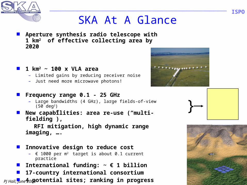
SKA At A Glance Aperture synthesis radio telescope
with 1 km2 of effective collecting area by 2020
1 km2 ~ 100 x VLA area – Limited gains by reducing receiver noise– Just need more microwave photons!
Frequency range 0.1 - 25 GHz– Large bandwidths (4 GHz), large fields-of-view (50
deg2) New capabilities: area re-use (“multi-
fielding”), RFI mitigation, high dynamic range
imaging, ….
Innovative design to reduce cost– € 1000 per m2 target is about 0.1 current practice
International funding: ~ € 1 billion 17-country international consortium 4 potential sites; ranking in progress
Hugedata rates& volumes
}
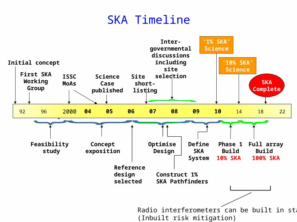
2000
Site short-listing
‘1% SKA’Science
ISSCMoAs
ScienceCase
published
Inter-governmental discussions
including site selection
First SKA WorkingGroup
Initial concept
2000
‘10% SKA’Science
92 96 04 05 06 07 08 09 10 14 18 22
Feasibility study
Full arrayBuild
100% SKA
SKAComplete
Phase 1Build
10% SKA
Conceptexposition
Define SKA
System
SKA Timeline
Optimise Design
Reference design selected
Construct 1% SKA Pathfinders
Radio interferometers can be built in stages(Inbuilt risk mitigation)
PJ Hall, June 2006
ISPO
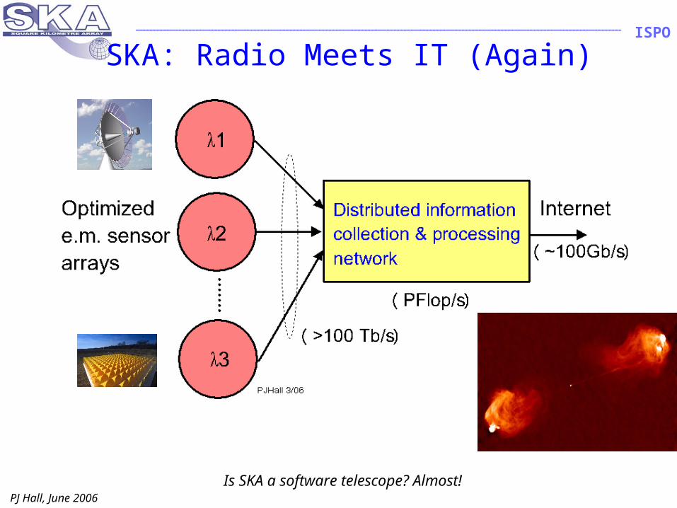
SKA: Radio Meets IT (Again)
Is SKA a software telescope? Almost!
PJ Hall, June 2006
ISPO
Reference Design - Background
Reference Design (RD)– Provides recognizable SKA image– Focuses science and engineering– Forms basis of SKA costing– Is a strong candidate for actual implementation
Result of wide exploration of design space– Original SKA concepts pushed boundaries in key areas: often
simultaneously!» Brightness sensitivity, field-of-view, no. FOVs, frequency coverage,
…» RD retains major precepts in each frequency range» All SKA concepts had/have much common system design
RD balances innovation and risk– Recognizes need to optimize within selected technology mix – Maps out technology contingencies
» Fall-back positions at every decision point
PJ Hall, June 2006
ISPO
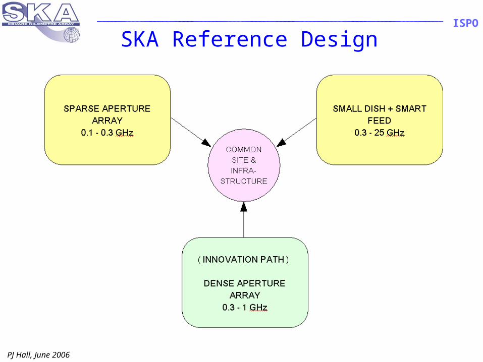
SKA Reference Design
PJ Hall, June 2006
ISPO
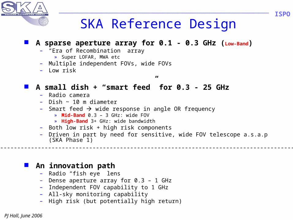
SKA Reference Design A sparse aperture array for 0.1 - 0.3 GHz (Low-Band)
– “Era of Recombination” array» Super LOFAR, MWA etc
– Multiple independent FOVs, wide FOVs– Low risk
A small dish + “smart feed” for 0.3 - 25 GHz– Radio camera– Dish ~ 10 m diameter– Smart feed wide response in angle OR frequency
» Mid-Band 0.3 – 3 GHz: wide FOV» High-Band 3+ GHz: wide bandwidth
– Both low risk + high risk components– Driven in part by need for sensitive, wide FOV telescope a.s.a.p (SKA Phase
1)
An innovation path– Radio “fish eye” lens– Dense aperture array for 0.3 – 1 GHz– Independent FOV capability to 1 GHz– All-sky monitoring capability– High risk (but potentially high return)
-----------------------------------------------------------------------------------------------------------------------
PJ Hall, June 2006
ISPO
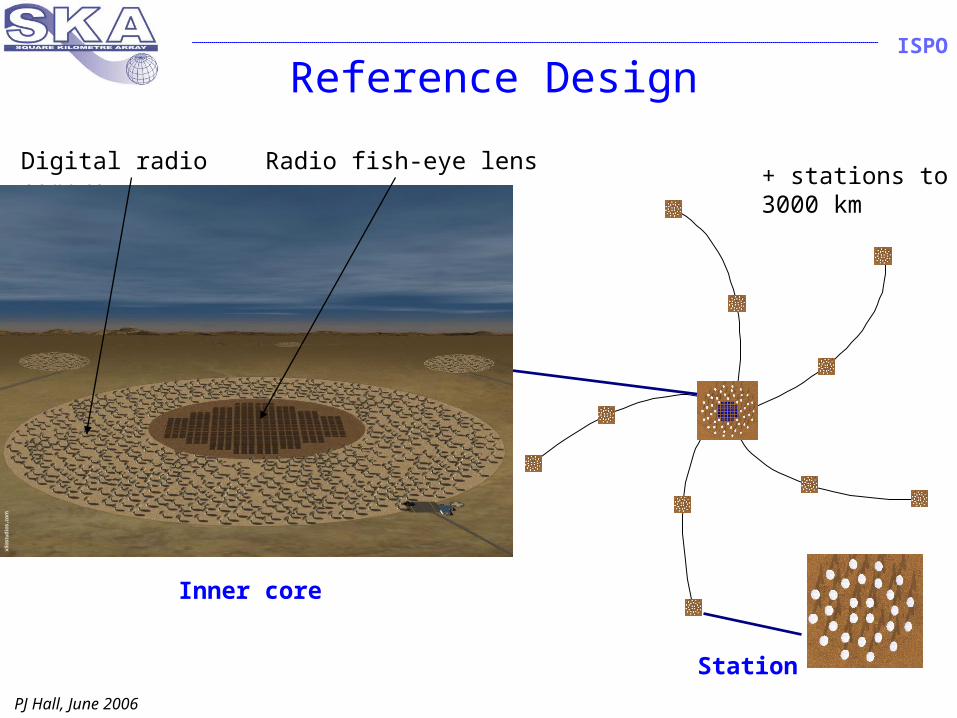
radio “fish-eye lens”
Inner core
Station
Digital radio camera+ stations to3000 km
Radio fish-eye lens
Reference Design
PJ Hall, June 2006
ISPO
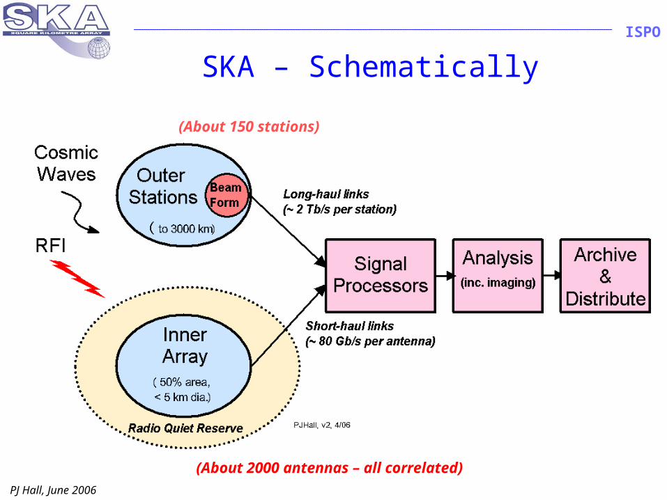
SKA – Schematically
(About 150 stations)
(About 2000 antennas – all correlated)

PJ Hall, June 2006
ISPO
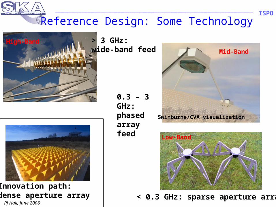
Reference Design: Some Technology
> 3 GHz: wide-band feed
< 0.3 GHz: sparse aperture array
0.3 – 3 GHz:phased arrayfeed
Innovation path: dense aperture array
Mid-Band
High-Band
Swinburne/CVA visualization
Low-Band
PJ Hall, June 2006
ISPO
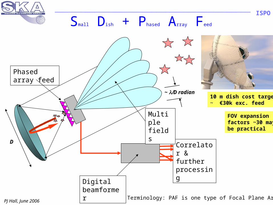
Small Dish + Phased Array Feed
Digital beamformer
Phased array feed
Correlator & further processing
Multiple fields
10 m dish cost target:~ €30k exc. feed
FOV expansion factors ~30 maybe practical
~ D radian
D
Terminology: PAF is one type of Focal Plane Array
PJ Hall, June 2006
ISPO
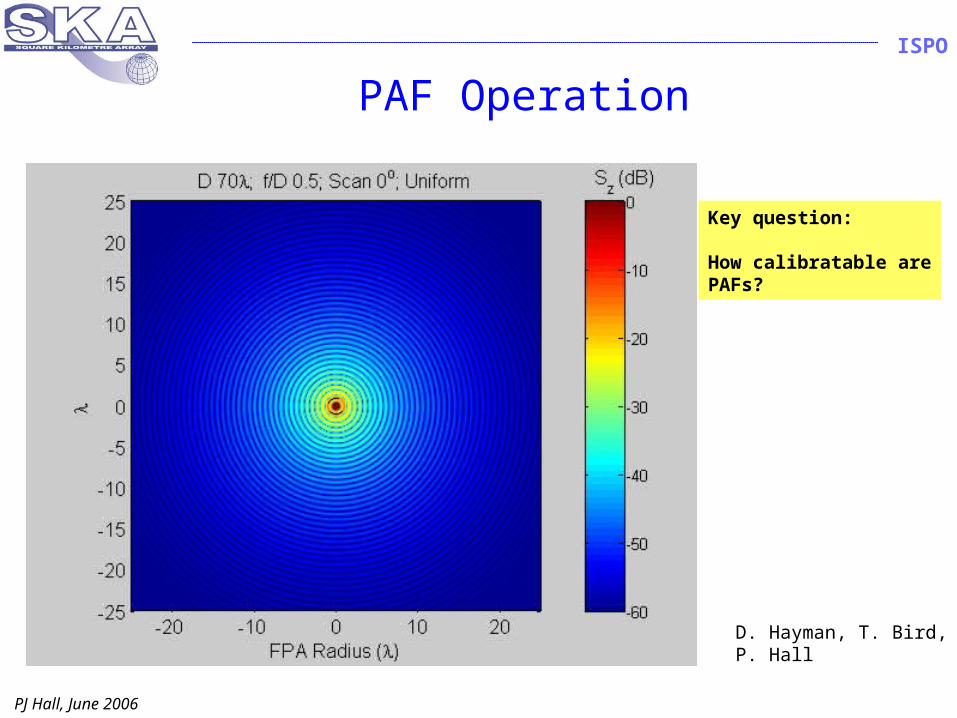
PAF Operation
Key question:
How calibratable arePAFs?
D. Hayman, T. Bird,P. Hall
PJ Hall, June 2006
ISPO
Reference Design Practicalities Full frequency range unlikely to be affordable
– Possible outcome: (EoR array) + (0.3 – 10 GHz) Dense AA is least mature technology in cost terms
– Balance between AA and SD collecting area will depend on cost and performance demonstration
– AA probably has most scientific value as a central collecting area But SD+PAFs also need rapid demonstration
– Cheap dishes and astronomically-capable PAFs are not trivial– Low frequency efficiency is a potential issue
Ultimate contingency if AA, SD+PAF fail:– Super-LOFAR, 0.1 - 0.3 GHz, plus– “small” dishes (~10 m) + single pixel feed, > 0.3 GHz
» 7 deg2 FOV at 0.7 GHz; “small” FOV partially compensated by better Aeff/Tsys
Large-scale cost – performance estimation begins Q4 ’06– Closely allied with variational analysis wrt science goals– Strawman design for forthcoming Paris meeting
PJ Hall, June 2006
ISPO
Wide Fields Same FOV same no. of receiver chains
– Concept independent (almost) Many small antennas correlator intensive
– Small dishes or AA patches Fewer, larger antennas with FOV expansion
reduced correlator load– Use focal plane beamforming to reduce order of correlation challenge
» Bigger dishes + PAF (or larger AA patches)» Big question: does extra PAF calibration cost negate correlator saving?
– Bigger antennas» Better low freq performance» More sensitive, easier to calibrate» Better RFI discrimination
– Smaller antennas» Probably more attractive production costing» Easier to calibrate?
Low & mid-band wide-FOV operation fits within processing envelope defined by high band SKA spec.
PJ Hall, June 2006
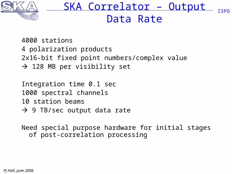
ISPOSKA Correlator – Output Data Rate
4000 stations4 polarization products2x16-bit fixed point numbers/complex value 128 MB per visibility set
Integration time 0.1 sec 1000 spectral channels10 station beams 9 TB/sec output data rate
Need special purpose hardware for initial stages of post-correlation processing
PJ Hall, June 2006
ISPO
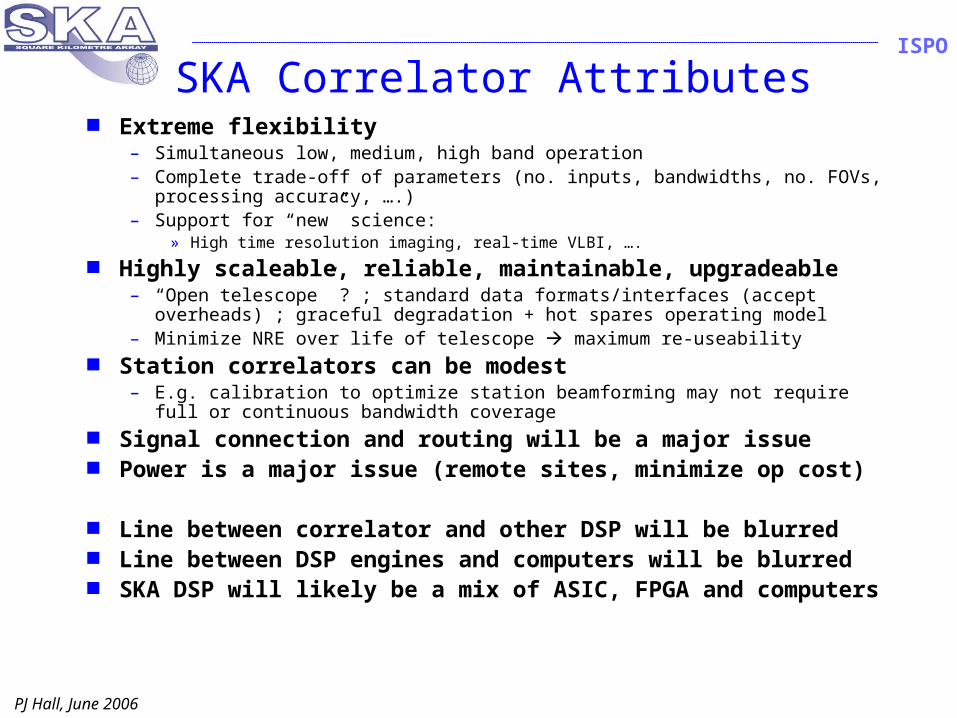
SKA Correlator Attributes Extreme flexibility
– Simultaneous low, medium, high band operation– Complete trade-off of parameters (no. inputs, bandwidths, no. FOVs,
processing accuracy, ….)– Support for “new” science:
» High time resolution imaging, real-time VLBI, ….
Highly scaleable, reliable, maintainable, upgradeable– “Open telescope” ? ; standard data formats/interfaces (accept overheads)
; graceful degradation + hot spares operating model– Minimize NRE over life of telescope maximum re-useability
Station correlators can be modest– E.g. calibration to optimize station beamforming may not require full or
continuous bandwidth coverage Signal connection and routing will be a major issue Power is a major issue (remote sites, minimize op cost)
Line between correlator and other DSP will be blurred Line between DSP engines and computers will be
blurred SKA DSP will likely be a mix of ASIC, FPGA and
computers
PJ Hall, June 2006
ISPO
SKA – Many Other Challenges
Low-noise, integrated, receivers– E.g. millions-off for mid-band
High speed data transport– Looking for 100 Gb/s trans-continental and trans-oceanic
Signal processing– beyond just correlation (IM, tied array modes, …)
Post-processing– 2015-2020 computing capacity will limit initial science but
cannot dominate system design– Archive and sharing of data will be a major challenge
Pathfinders and demonstrators are pivotal– Allen Telescope Array, LOFAR, xNTD, Karoo Array
Telescope, DSNA, APERTIF, EMBRACE, 2-PAD ….– €200M committed so far; €80M explicitly for SKA;
additional €40M expected in China shortly
PJ Hall, June 2006
ISPO
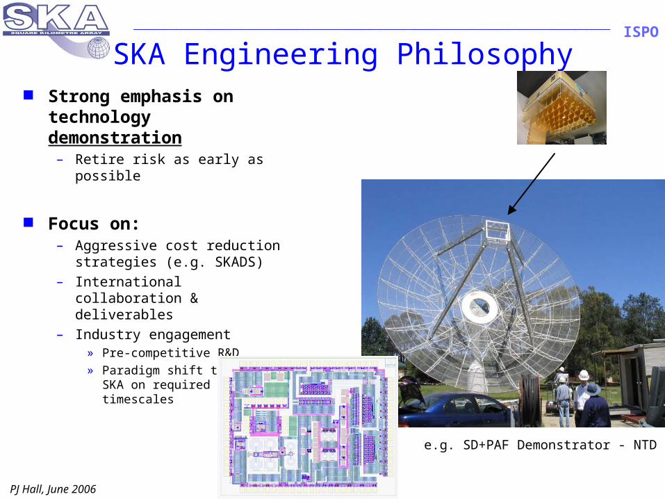
SKA Engineering Philosophy Strong emphasis on
technology demonstration – Retire risk as early as
possible
Focus on:– Aggressive cost reduction
strategies (e.g. SKADS)– International collaboration
& deliverables– Industry engagement
» Pre-competitive R&D» Paradigm shift to deliver
SKA on required timescales
e.g. SD+PAF Demonstrator - NTD
PJ Hall, June 2006
ISPO
Current SKA Happenings Site assessment
– RFI and other studies complete; list of “acceptable” or “qualified” sites soon
Funding agencies and SKA– Formed Inter-agency Working Group; continuing engagement
Funding opportunities (e.g. ESFRI) Forthcoming Engineering – Science meeting
– Paris, 4-8 Sept– Emphasis on Reference Design, project costing
International engineering review Q4/07 – Q1/08– Reference Design, specifications, …
Continued science and engineering exposition More outreach
– New animations, telescope model, …. More industry engagement
– Major structural, governance implications More inter-region collaboration
– Easier as technology concepts coalesce
PJ Hall, June 2006
ISPO
Summary
Site selection in progress Reference Design identified RD technologies being developed via
regional pathfinders– Rapidly increasing inter-region collaboration
Initial SKA system design in progress– Incl. cost and performance modelling– Preliminary engineering reviews 2007-08
Industry interaction increasing SKA Phase 1 - start 2011