Embed Size (px)
Citation preview
ACI MATERIALS JOURNAL TECHNICAL PAPER Title no. 88-M40
Size Effect in Brazilian Split-Cylinder Tests: Measurements and Fracture Analysis
I] "
by Zdenek P. Satant, Mohammad Taghi Kazemi, Toshiaki Hasegawa, and Jacky Mazars
Size effect in the split-eylinder (Brazilian) tensile test is studied experimentally and analyzed theoretically. Tests of a very brood size range, 1:26, were conducted on cylindrical discs of constant thickness made from concrete with aggregate of a maximum size of 5 mm (2 in.). The results confirm the existence of size effect and show that up to a certain critical diameter d, the curve of nominal strength vel'lUS diameter approximately agrees with the law proposed by Ba};ant for the size effect caused by energy release due to fracture growth. For larger sizes, there appears to ~ a deviation from the siz.e-effect law, although large scatter of the test results does not permit a strong con
-elusion in this regard. The trend of the size-effect curve is probably an approach to a horizontal asymptote with or without a reversal of slope of the size-effect curve. The reversal can be explained by a modification of the size-effect law in which the crack length at failure ceases 10 increase in proponion 10 the diameter and may remain constant for sizes larger than a certain characteristic size. The approoch to a horizontal asymptote can be explained by plastic slip-on triaxially confined wedge-shaped regions below the platens.
K.ywords: cylinders; failure; fracturt p~rtJ~; siu sc~nin&; splittiae t •• slk stTnetl!; tem.
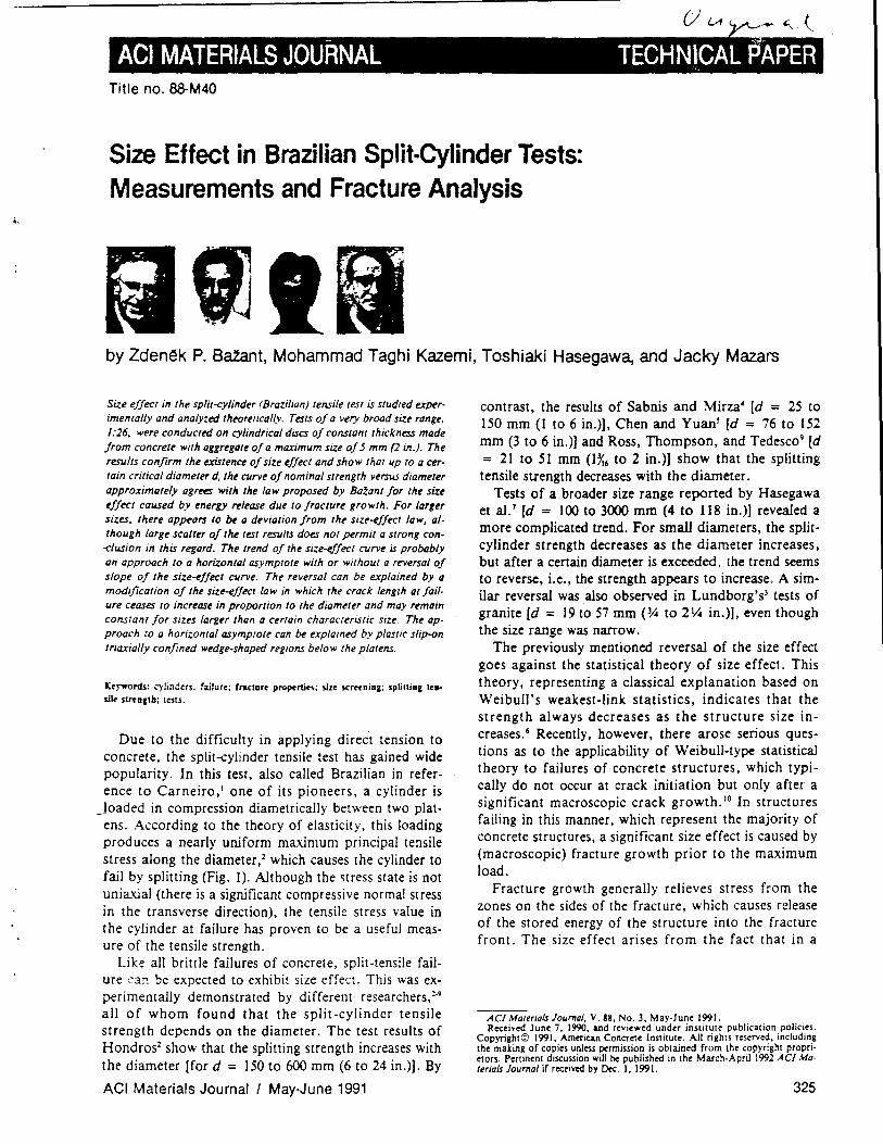
Due to the difficulty in applying direct tension to concrete, the split-cylinder tensile test has gained wide popularity. In this test, also called Brazilian in reference to Carneiro,t one of its pioneers, a cylinder is
Joaded in compression diametrically between two platens. According to the theory of elasticity, this loading produces a nearly uniform maximum principal tensile stress along the diameter,2 which causes the cylinder to fail by splitting (Fig. I). Although the stress state is not uniaxial (there is a significant compressive normal stress in the transverse direction), the tensile stress value in the cylinder at failure has proven to be a useful measure of the tensile strength.
Like all brittle failures of concrete, split-tensile failure can be expected to exhibit size effect. This was experimentally demonstrated by different researchers,2.9 alI of whom found that the split-cylinder tensile strength depends on the diameter. The test results of Hondros2 show that the splitting strength increases with the diameter [for d = 150 to 600 mm (6 to 24 in.)]. By
ACI Materials Journal I May-June 1991
contrast, the results of Sabnis and Mirza4 [d = 25 to 150 mm (1 to 6 in.)], Chen and Yuan l [d = 76 to 152 mm (3 to 6 in.)] and Ross, Thompson, and Tedesc09 [d = 21 to 51 mm (lX, to 2 in.)] show that the splitting tensile strength decreases with the diameter.
Tests of a broader size range reported by Hasegawa et al.' [d = 100 to 3000 mm (4 to 118 in.)] revealed a more complicated trend. For small diameters, the splitcylinder strength decreases as the diameter increases, but after a certain diameter is exceeded, the trend seems to reverse, i.e., the strength appears to increase. A similar reversal was also observed in Lundborg's) tests of granite Cd = 19 to 57 mm (~ to 2 ~ in.)], even though the size range was narrow.
The previously mentioned reversal of the size effect goes against the statistical theory of size effect. This theory, representing a classical explanation based on WeibuII's weakest-link statistics, indicates that the strength always decreases as the structure size increases. 6 Recently, however, there arose serious questions as to the applicability of Weibull-type statistical theory to failures of concrete structures, which typically do not occur at crack initiation but only after a significant macroscopic crack growth. to In structures failing in this manner, which represent the majority of concrete structures, a significant size effect is caused by (macroscopic) fracture growth prior to the maximum load.
Fracture growth generally relieves stress from the zones on the sides of the fracture, which causes release of the stored energy of the structure into the fracture front. The size effect arises from the fact that in a
ACI Malertals Journal, V. 88, No.3, May-June 1991. Received June 7, 1990, and reviewed under institute publication policies.
Copyright© 1991. American Concrete Institute. All rights reserved, including the making of copies unless permission is obtained from the copyright proprio etors. Pertinent discussion will be published in the March·Aprii 1992 A CI Materials Journal if received by Dec. I, 1991.
325
Ztlmlk P. 84tAlr/, FACI. is l4'allrr P. MllrpII .. · Profnsor of CIvil EIt'lflnrlnl al Nortlt>WSI~"" UnlwfSlly. EvaflSlon /limo ... wlt~1Y Itt suwd as fOllfldml d" IYCI0r of Ih~ C~fllrr for COnCIYI~ and (rl>omal~flQls. Ht IS a IYgUltlYd SlrvC· Illral rnlinrt!r. a collSllllant 10 Arronlle NatlONlI LAboratory. and ~/IM·ifl· clri(/ of Ih~ ASCE Journal of Engineering ~echanics. H~ is Chairman of ACI Commlllrt! 446. Fraelilre M«ltan/cs; and member of ACI Commill~ ]()9.
C_p and Shrmkage of ConClYle; afld 3~. Struclilral Stifely; afld .. Chairman of RILEM Commillrt! TC 107 on Creep. of ASCE·EMD Programs Commit· trt!. and of SMiRT Division of Concme afld Nonmelallic Mal~ria/s; lind is a member of Ihe 80ard of DilYClors of Ihe Soci~'.v of Enlinrt!ring Sc~flcr. o.r. IYnt/y. h~ conduCIS IYStQrch althe T«hnieal Un/wrsily in Munich under Hllm· boldl A ward of U.S. Stnior Scitnlisl.
ACI m~mber MohommtJd Talhi /(aumi IYCtIV~ his PhD in civil enginrt!riflg from Norrhwt!Ste,." UnlversilY m 1990. He holds MS and 8S degrtt!S IfI Slrvctural englflrt!rmg from Shartf U",verslly of Technology at Tehran. whtlY he currently .. a faculty member. His research illterests include fracture m«hanlcs of concrete and olher qllasi·brillie materials.
ACI member Toshillki HllStlaWQ is a slructural resNrch engmeer 01 Shimizu Corporal ion. Tokyo. Japan. He IYceiv~ bolh h .. 8E and .'.IS degtYeS in civil engineeriflg from WllStda Universily. Tokyo. He is a member of ACI Commil' It!t 446. Fraclure MechanICS. and is a member of Ihe Japan Concrele IlISli· IUle's T«hnical Commillee on Fracture Mtchanics of COflcrele. His resHrch interesls include Ihe constitulive relallOnsh:p. creep. shnnkage. and the fNlC' lure mechanics of concrele. He has been Q vislling scholar al Northweslern University conducling j01fl1 restareh on Ihe conslilillive law and fraclure m('
chanics of conerele.
ACI member Jacky MtWUJ is Professor of Civil Engineeriflg al Ihe Ecole Nor· male SuperieulY de Cachan. France. He is a member of ACI Commilltt #6. Fraclure Mechanics. and is aClively involv~ in research aelivilit!S dealing wilh
damage and fracture of plain and rei"fo~ conelYlt structures. Th~ aelivi· lit!S include new testing devices. modeling, and numerical implemenlalion i" fi· nile elemenl codt!S.
larger (geometrically similar) structure the release of the stored energy caused by a unit fracture extension is, at the same nominal stress, larger (assuming the fracture length at failure increases with the structure size), which means that a lower nominal stress suffices to produce the energy release required to break the material (the fracture energy)'O.1I This size effect, due to stored energy release, is ignored in the statistical theory, but in reality it takes precedence over the statistical size effect since it is deterministic (nonstatistical). The size effect that can be attributed to statistical phenomena could be only that remaining unaccounted for by the stored energy release.
p p .-0 " '. I,
V elaslicOy Y /
-d a
~-,-,,,,,,--
- contacI
(a) (b) (c)
Fig. I-(a) Elastic distribution of transverse normal stress in uncracked disc, (b) axial splitting, and (c) final failure mode with wedge formation and plastic slip
326
The purpose of the present paper is to examine the fracture mechanics type of size effect in the split-cylinder test and report new test results.
REVIEW OF SIZE EFFECT LAW The size effect in two dimensions is defined in terms
of nominal stress at failure
(1)
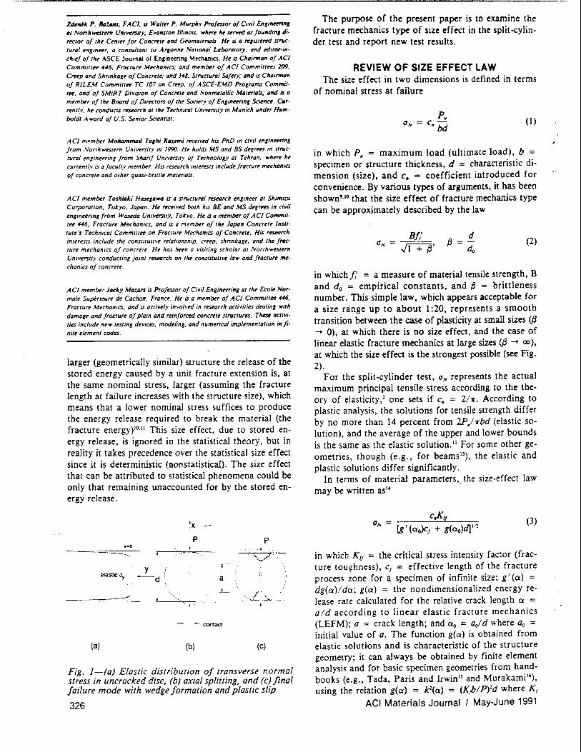
in which p. = maximum load (ultimate load), b = specimen or structure thickness, d = characteristic dimension (size), and c. = coefficient introduced for convenience. By various types of arguments, it has been shown'·lo that the size effect of fracture mechanics type can be approximately described by the law
B!,' (2)
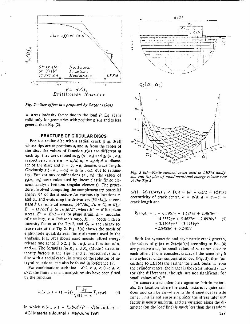
(1",= ~'
in which!,' = a measure of material tensile strength, B and do = empirical constants, and {3 = brittleness number. This simple law. which appears acceptable for a size range up to about I :20, represents a smooth transition between the case of plasticity at small sizes (J3 ~ 0), at which there is no size effect, and the case of linear elastic fracture mechanics at large sizes (f3 ~ 00), at which the size effect is the strongest possible (see Fig. 2).
For the split-cylinder test, (1", represents the actual maximum principal tensile stres~ according to the theory of elasticity,2 one sets if c. = 2IT. According to plastic analysis, the solutions for tensile strength differ by no more than 14 percent from 2P/Tbd (elastic solution), and the average of the upper and lower bounds is the same as the elastic solution. '2 For some other geometries, though (e,g., for beamsll), the elastic and plastic solutions differ significantly.
In terms of material parameters,. the size-effect law may be written as"
(3)
in which KIJ = the critical stress intensity factor (fracture toughness), cf = effective length of the fracture process zone for a specimen of infinite size; g' (a) = dg(a)/ da; g(a) = the nondimensionalized energy release rate calculated for the relative crack length a = aid according to linear elastic fracture mechanics (LEFM); a = crack length; and a o = aofd where aD = initial value of a. The function g(a) is obtained from elastic solutions and is characteristic of the structure geometry; it can always be obtained by finite element analysis and for basic specimen geometries from handbooks (e.g., Tada, Paris and Irwin'l and Murakami '6), using the relation g(a) = k2(a) = (Kpl P)2d where K/
ACI Materials Journal I May-June 1991
,+-I-=~-~ 1 size eff'ct ~\
1 Strength ! or Yield i
01 ! Criterion!
001 01
~,
Nonlinear Fracture Mechanics
.. ~. ~ I
'\~ ,LEFM I'
)( .
10
f3= d/do Brittleness Number
Fig. 2-Size-e//ect law proposed by Baloant (1984)
= stress intensity factor due to the load P. Eq. (3) is valid only for geometries with positive g' (a) and is less general than Eq. (2).
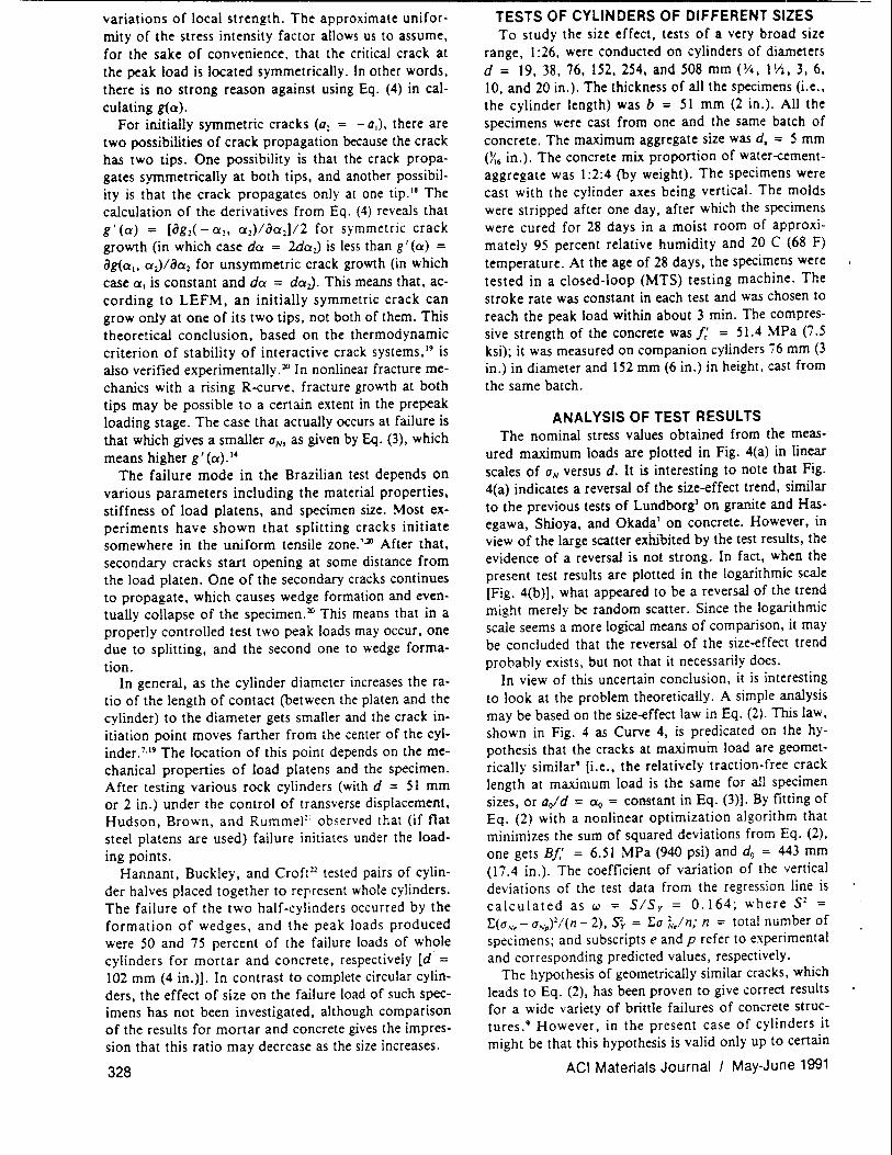
FRACTURE OF CIRCULAR DISCS For a circular disc with a radial crack [Fig. 3(a)]
whose tips are at positions 0 , and O2 from the center of the disc, the values of function g(a) are different at each tip; they are denoted as g, (ai, aJ and g2 (ai, aJ, respectively, where a , = a/d, a 2 = a2/d; d = diame- -ter of the disc; and a = a2 - a, denotes crack length. Obviously g,( - a2' - a ,) = g2 (ai, aJ, due to symmetry. For various combinations (ai, a2), the values of g2(a
" a 2) were calculated by linear elastic finite ele
ment analysis (without singular elements). The procedure involved computing the complementary potential energy <1>. of the structure for various tip locations 0 ,
and a2, and evaluating the derivatives [a<l>/aojp at constant P by finite differences; [a<l>· 1 aaJp! b = G2 = K; / E' = (Plbd)2 gl (a" a.JdIE', where E' = E for plane stress, E' = EI(l - v) for plane strain, E = modulus of elasticity, JI = Poisson's ratio, Kil = Mode 1 stress intensity factor at the Tip 2, and G l = the energy release rate at the Tip 2. Fig. 3(a) shows the mesh of eight"node quadrilateral finite elements used in the analysis. Fig. 3(b) shows nondimensionalized energy release rate at the Tip 2, g2 (a" al)' as a function of a, and a2' The formulas for Kn and K12 (Mode I stress intensity factors at the Tips I and 2, respectively) for a disc with a radial crack. in terms of the solution of integral equations. can also be found ill Reference 17.
For combinations such that - d/2 < 0, < 0 < OJ < dl2. the finite element analysis results have been fitted by the function
(4)
in which k1(a,. a2) = K12 b../d 1 P = "/g(a ,• a2), 'Y = ACI Materials Journal I May-June 1991
II I
• u "-.... N
Fig. 3 (a)-Finite element mesh used in LEFM analysis, and (b) plot 0/ nondimensional energy release rare at the Tip 2
a/(1- 2e) (always 'Y < I). e = (a, + aJ/2 = relative eccentricity of crack center, a = old, a = a2 - a , = crack length and
7(2 h,e) = 1 - O.7967'Y + l.5247e -+ 2.4676-y: - 4.S3S7'Ye + S.4627e 2 - 2.092(}y l (5) + 3.ISOS'Ye 2 - 3.4934Yf - 2.9488el + O.2487e'
Both for symmetric and asymmetric crack growth, the values of g'(a) = 2k(a)k'(a) according to Eq. (4) are positive and, for small values of a, rather c1os(! to each other. If one considers cracks of the same length in a cylinder under concentrated load (Fig. 3), then (according to LEFM) the farther the crack center is from the cylinder center, the higher is the stress intensity factor (the differences, though, are not significant for small values of a).'6
In concrete and other heterogeneous brittle materials, the location where the crack initiates is quite random and can be anywhere in the diametrical tensile zone. This is not surprising since the stress intensity factor is nearly uniform, and its variation along the diameter (on the load line) is much less than the random
327
variations of local strength. The approximate uniformity of the stress intensity factor allows us to assume, for the sake of convenience, that the critical crack at the peak load is located symmetrically. In other words, there is no strong reason against using Eq. (4) in calculating g(a).
For initially symmetric cracks (a2 = - a l ). there are two possibilities of crack propagation because the crack has two tips. One possibility is that the crack propagates symmetrically at both tips, and another possibility is that the crack propagates only at one tip. II The calculation of the derivatives from Eq. (4) reveals that g / (a) = [Og2( - a l • (2)/oal]12 for symmetric crack growth (in which case da = 2dal) is less than g / (a) = og(a1, aJ/oa2 for unsymmetric crack growth (in which case a l is constant and da = daJ. This means that, according to LEFM, an initially symmetric crack can grow only at one of its two tips, not both of them. This theoretical conclusion, based on the thermodynamic criterion of stability of interactive crack systems,19 is also verified experimentally.ltl In nonlinear fracture mechanics with a rising R-curve, fracture growth at both tips may be possible to a certain extent in the prepeak loading stage. The case that actually occurs at failure is that which gives a smaller UN' as given by Eq. (3), which means higher g'(a).14
The failure mode in the Brazilian test depends on various parameters including the material properties, stiffness of load platens, and specimen size. Most experiments have shown that splitting cracks initiate somewhere in the uniform tensile zone.1~ After that, secondary cracks start opening at some distance from the load platen. One of the secondary cracks continues to propagate, which causes wedge formation and eventually collapse of the specimen. ltl This means that in a properly controlled test two peak loads may occur, one due to splitting, and the second one to wedge formation.
In general, as the cylinder diameter increases the ratio of the length of contact (between the platen and the cylinder) to the diameter gets smaller and the crack initiation point moves farther from the center of the cylinder.7,19 The location of this point depends on the mechanical properties of load platens and the specimen. After testing various rock cylinders (with d = 51 mm or 2 in.) under the control of transverse displacement, Hudson, Brown, and RummeF' observed that (if flat steel platens are used) failure initiates under the loading points.
Hannant, Buckley, and Croft ll tested pairs of cylinder halves placed together to represent whole cylinders. The failure of the two half-cylinders occurred by the formation of wedges, and the peak loads produced were 50 and 75 percent of the failure loads of whole cylinders for mortar and concrete, respectively [d = 102 mm (4 in.)]. In contrast to complete circular cylinders, the effect of size on the failure load of such specimens has not been investigated, although comparison of the results for mortar and concrete gives the impression that this ratio may decrease as the size increases.
328
TESTS OF CYLINDERS OF DIFFERENT SIZES To study the size effect, tests of a very broad size
range. I :26. were conducted on cylinders of diameters d = 19, 38. 76. 152. 254. and 508 mm (3/4. 1 v.. 3. 6. 10. and 20 in.). The thickness of all the specimens (i.e .• the cylinder length) was b = 5 I mm (2 in.). All the specimens were cast from one and the same batch of concrete. The maximum aggregate size was d. = 5 mm (X6 in.). The concrete mix proportion of water~mentaggregate was I :2:4 (by weight). The specimens were cast with the cylinder axes being vertical. The molds were stripped after one day. after which the specimens were cured for 28 days in a moist room of approximately 95 percent relative humidity and 20 C (68 F) temperature. At the age of 28 days, the specimens were tested in a closed-loop (MTS) testing machine. The stroke rate was constant in each test and was chosen to reach the peak load within about 3 min. The compressive strength of the concrete was f: = 51.4 MPa (7.5 ksi); it was measured on companion cylinders i6 mm (3 in.) in diameter and 152 mm (6 in.) in height, cast from the same batch.
ANALYSIS OF TEST RESULTS The nominal stress values obtained from the meas
ured maximum loads are plotted in Fig. 4(a) in linear scales of UN versus d. It is interesting to note that Fig. 4(a) indicates a reversal of the size-effect trend, similar to the previous tests of Lundborg) on granite and Hasegawa, Shioya, and Okada' on concrete. However. in view of the large scatter exhibited by the test results, the evidence of a reversal is not strong. In fact, when the present test results are plotted in the logarithmic scale [Fig. 4(b)], what appeared to be a reversal of the trend might merely be random scatter. Since the logarithmic scale seems a more logical means of comparison, it may be concluded that the reversal of the size-effect trend probably exists. but not that it necessarily does.
In view of this uncertain conclusion. it is interesting to look at the problem theoretically. A simple analysis may be based on the size-effect law in Eq. (2). This law. shown in Fig. 4 as Curve 4, is predicated on the hypothesis that the cracks at maximum load are geometrically similar' [i.e., the relatively traction-free crack length at maximum load is the same for all specimen sizes, or ar! d = ClQ = constant in Eq. (3)]. By fitting of Eq. (2) with a nonlinear optimization algorithm that minimizes the sum of squared deviations from Eq. (2). one gets Bf.' = 6.51 MPa (940 psi) and do = 443 mm (17.4 in.). The coefficient of variation of the vertical deviations of the test data from the regression line is calculated as w = 5/5 y = 0.164; where 52 = E(aNt - uNp)2/(n - 2). 52y = Ea ~t/n; n = total number of specimens; and subscripts e and p refer to experimental and corresponding predicted values, respectively.
The hypothesis of geometrically similar cracks, which leads to Eq. (2). has been proven to give correct results for a wide variety of brittle failures of concrete structures. 9 However, in the present case of cylinders it might be that this hypothesis is valid only up to certain
ACI Materials Journal I May-June 1991
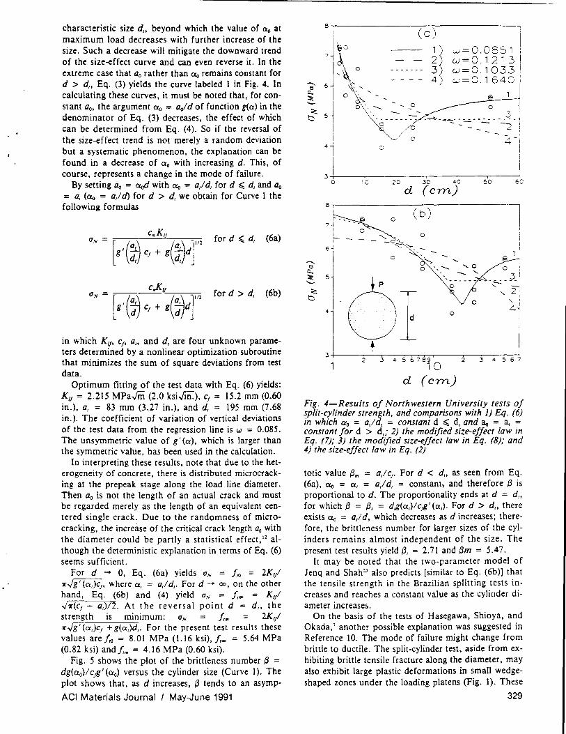
characteristic size d" beyond which the value of ao at maximum load decreases with further increase of the size. Such a decrease will mitigate the downward trend of the size-effect curve and can even reverse it. In the extreme case that ao rather than CXo remains constant for d > d" Eq. (3) yields the curve labeled 1 in Fig. 4. In calculating these curves, it must be noted that, for constant ao, the argument a o = Ooid of function g(a) in the denominator of Eq. (3) decreases, the effect of which can be determined from Eq. (4). So if the reversal of the size-effect trend is not merely a random deviation but a systematic phenomenon, the explanation can be found in a decrease of a o with increasing d. This, of course, represents a change in the mode of failure.
By setting ao = ¥ with ao = a,l dt for d ~ dt and ao = at (00 = a,ld) for d > dt we obtain for Curve 1 the following formulas
for d ~ d t (6a)
for d > dt (6b)
in which Kif' cf , a" and d, are four unknown parameters determined by a nonlinear optimization subroutine that minimizes the sum of square deviations from test data.
Optimum fitting of the test data with Eq. (6) yields: KlJ = 2.215 MParm (2.0 ksiJii1.), cf = 15.2 mm (0.60 in.), at = 83 mm (3.27 in.), and dt = 195 mm (7.68 in.). The coefficient of variation of vertical deviations of the test data from the regression line is w = 0.085. The unsymmetric value of g' (a), which is larger than the symmetric value, has been used in the calculation.
In interpreting these results, note that due to the heterogeneity of concrete, there is distributed microcracking at the prepeak stage along the load line diameter. Then ao is not the length of an actual crack and must be regarded merely as the length of an equivalent centered single crack. Due to the randomness of microcracking, the increase of the critical crack length ao with the diameter could be partly a statistical effect,I2 although the deterministic explanation in terms of Eq. (6) seems sufficient.
For d ... 0, Eq. (6a) yields 0" = frO = 2KlJI 7(.Jg' (o.,)c" where at = a,l d,. For d -+ 00, on the other hand, Eq. (6b) and (4) yield aN = 1,~ = K,/ .J7(cf + at)/2. At the reversal point d = d" the strength is mlDlmum: a.. 1,,,, 2K,/ 7(.Jg' (at)e, + g(at)dt. For the present test results these values are frO = 8.01 MPa (1.16 ksi),1,,,,, = 5.64 MPa (0.82 ksi) and 1,,,, = 4.16 MPa (0.60 ksi).
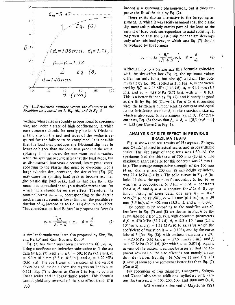
Fig. 5 shows the plot of the brittleness number 13 = dg(ao)/ c ~' (ao) versus the cylinder size (Curve 1). The plot shows that, as d increases, f3 tends to an asymp-
ACI Materials Journal I May·June 1991
8~--------------~~------------
I (0) I
___ 67],~O 1j w=0.0851 \ - - 2 w=0.12131
o ------- 3 w=O.l 033 I - - - - 4 w=O 1640 I
~ \)': , " J ~ J ° ~',>, ,0 ~-1-'i ; 5 II' ~···o-:-:--?-~-:.~--~--4-1
/ - - I
I / 0 - 4.-' 4(
3~1-----'-----------r----~----~o
8.------------------------------7
o
5
4 I
o i
__ ~ 1 i ~...... )"---11
o ',---- ...... 0 0 " _...... ~,
'c: -----'::. -~~ -::-- i .... 2
o 4
3+-----~ __ --~_r~~----~------~r_i 56789 2 34567
10 d (ern)
Fig. 4-Results of Northwestern University tests of split-cylinder strength, and comparisons with 1) Eq. (6) in which ao = a/d, = constant d ~ d, and ao = a. = constant for d > d,; 2) the modified size-effect law in Eq. (7); 3) the modified size-effect law in Eq. (8); and 4) the size-effect law in Eq. (2)
totic value 13,. = a,lc,. For d < d" as seen from Eq. (6a), ao = a, = a/ d, = constant, and therefore f3 is proportional to d. The proportionality ends at d = d" for which 13 = 13, = d,g(a,)1 c.£' (a,). For d > d" there exists CXo = a/ d, which decreases as d increases; therefore, the brittleness number for larger sizes of the cylinders remains almost independent of the size. The present test results yield f3t = 2.71 and 13m = 5.47.
It may be noted that the two-parameter model of Jenq and Shah;] also predicts [similar to Eq. (6b)] that the tensile strength in the Brazilian splitting tests increases and reaches a constant value as the cylinder diameter increases.
On the basis of the tests of Hasegawa, Shioya, and Okada,' another possible explanation was suggested in Reference 10. The mode of failure might change from brittle to ductile. The split-cylinder test, aside from exhibiting brittle tensile fracture along the diameter, may also exhibit large plastic deformations in small wedgeshaped zones under the loading platens (Fig. 1). These
329
f~----------------------------------
f3m=5.47 - - - - - - - - - -
~ 1/ Eq. (6) . /
/
i i' ~.
o : I i (; 20 4C 60 8e
d (ern)
Fig. 5-Brittleness number versus the diameter in the Brazilian tests based on 1) Eq. (6); and 2) Eq. 8
wedges, whose size is roughly proportional to specimen size, are under a state of high confinement, in which case concrete should be nearly plastic. A frictional plastic slip on the inclined sides of the wedge is required for the failure to be completed. It is possible that the load that produces the frictional slip may be lower or higher than the load that produces the actual splitting. If it is lower, the maximum load is reached when the splitting occurs; after that the load drops. but as displacement increases a second, lower peak, corresponding to the plastic slip must be overcome. For a large cylinder size, however, the size effect [Eq. (2)] may cause the splitting load peak to become less than Jhe plastic slip load peak, and in that case the maximum load is reached through a ductile mechanism, for which there should be no size effect. Therefore, the nominal stress (J,.. = (Jy corresponding to the ductile mechanism represents a lower limit on the possible reduction of (IN [according to Eq. (2)] due to size effect. This consideration lead Baiant9 to propose the formula
d {3 = -
do (7)
A similar formula was later also proposed by Kim, Eo. and Park,~- and Kim, Eo, and Koo.2~
Eq. (7) has three unknown parameters BJ/ , do. (J,.
Using a nonlinear optimization subroutine to fit the test data by Eq. (7) results in B/,' = 502 MPa (72.8 ksi), do = 6.3 x 10-- mm (2.5 x 10- 5 in.), and (J, = 4.20 MPa (0.61 ksi). The coefficient of variation of the vertical deviations of test data from the regression line is w = 0.121. Eq. (7) is shown as Curve 2 in Fig. 4, both in linear scales and in logarithmic scales. This formula cannot yield any reversal of the size-effect trend, if it
330
indeed is a systematic phenomenon, but it does improve the fit of the data by Eq. (2).
There exists also an alternative to the foregoing argument, in which it was tacitly assumed that the plastic slip mechanism already carries part of the load at the instant of load peak corresponding to axial splitting. It may well be that the plastic slip mechanism develops only after this load peak, in which case Eq. (7) should be replaced by the formula
( B/") d (IN = max ~,(J" {3
,,1 + {3 - do (8)
Although up to a certain size this formula coincides with the size-effect law (Eq. 2), the optimum values differ not only for (J~ but also If"r' and do. The optimum fit by Eq. (8), labeled as 3 in Fig. 4, is characterized by B/,' = 7.76 MPa (1.13 ksi), do = 91.4 mm (3.6 in.), and (Jy = 4.88 MPa (0.71 ksi), with w = 0.103. This is a better fit than by Eq. (7), and is nearly as good as the fit by Eq. (6) (Curve 1). For d ~ d, (transition size), the brittleness number remains constant and equal to the brittleness number {3, at the transition size d" which is also equal to its maximum value {3,.. For present tests, Eq. (8) shows that {3,. = f3, = [(BJ: /(Jy)2 - 1]
1.53 (see Curve 2 in Fig. 5).
ANALYSIS OF SIZE EFFECT IN PREVIOUS BRAZILIAN TESTS
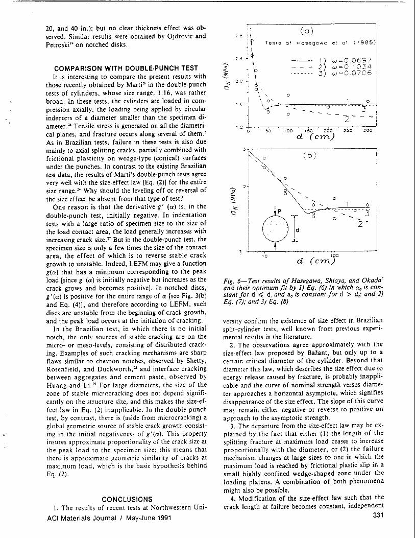
Fig. 6 shows the test results of Hasegawa, Shioya, and Okada' plotted in actual scales and in logarithmic scales. The size range of these tests was 1 :30. All the specimens had the thickness of 500 mm (20 in.). The maximum aggregate size for this concrete was 25 mm (1 in.). The average compressive strength of the 100 mm (4 in.) diameter and 200 mm (8 in.) height cylinders. was 23.4 MPa (3.4 ksi). The solid curves in Fig. 6 (labeled 1) show the optimum fit according to Eq. (6) in which ao is proportional to d (~ = a,/ d, = constant) for d ~ d" and ao = a, = constant for d ~ d,. By optimum fitting of these data, one gets Kif = 0.62 MPaJffi (0.56 ksi..;rn.), cf = 10 mm -(0.4 in.), a, = 89 mm (3.5 in.), d, = 402 mm (15.8 in.), and w = 0.070.
The optimum fit according to the modified size-effect laws in Eq. (7) and (8) are shown in Fig. 6 by the curve labeled 2 [for Eq. (7)]. with optimum parameters B /,' = 570 MPa (82.7 ksi), do = 5.3 x 10-- mm (2.1 x 10- 5 in.), and /, = 1.13 MPa (0.16 ksi) (for which the coefficient of variation is w = 0.103), and by the curve labeled 3 [for Eq. (8)]. with optimum parameters Bf,'
= 4.20 MPa (0.61 ksi), do = 57.9 mm (2.3 in.), and /. = 1.57 MPa (0.23 ksi) (for which w = 0.071)]. Again, in view of the scatter, it cannot be asserted that the apparent reversal of the size effect is not merely a random deviation, but Eq. (6) (Curve 1) and Eq. (8) (Curve 3) seem to give somewhat better fits than Eq. (7) (Curve 2).
For specimens of 1-m diameter, Hasegawa, Shioya, and Okada' also tested additional cylinders with various thicknesses, b = 100,200,500, and 1000 mm (4, 8,
ACI Materials Journal I May-June 1991
20, and 40 in.); but no clear thickness effect was observed. Similar results were obtained by Ojdrovic and Petroski I' on notched disks.
COMPARISON WITH DOUBLE·PUNCH TEST It is interesting to compare the present results with
those recently obtained by Marti 16 in the double-punch tests of cylinders, whose size range, I: 16, was rather broad. In these tests, the cylinders are loaded in compression axially, the loading being applied by circular indenters of a diameter smaller than the specimen diameter. ~ Tensile stress is generated on all the diametrical planes, and fracture occurs along several of them.s As in Brazilian tests, failure in these tests is also due mainly to axial splitting cracks, partially combined with frictional plasticity on wedge-type (conical) surfaces under the punches. In contrast to the existing Brazilian test data, the results of Marti's double-punch tests agree very well with the size-effect law [Eq. (2)] for the entire size range."' Why should the leveling off or reversal of the size effect be absent from that type of test?
One reason is that the derivative g I (0:) is, in the double-punch test, initially negative. In indentation tests with a large ratio of specimen size to the size of the load contact area, the load generally increases with increasing crack size. 27 But in the double-punch test, the specimen size is only a few times the size of the contact area, the effect of which is to reverse stable crack growth to unstable. Indeed, LEFM may give a function g(O') that has a minimum corresponding to the peak load [since g' (0:) is initially negative but increases as the crack grows and becomes positive]. In notched discs, g I (0') is positive for the entire range of 0' [see Fig. 3(b) and Eq. (4)], and therefore according to LEFM, such discs are unstable from the beginning of crack growth, and the peak load occurs at the initiation of cracking.
In the Brazilian test, in which there is no initial notch, the only sources of stable cracking are on the micro- or meso-levels, consisting of distributed cracking. Examples of such cracking mechanisms are sharp flaws similar to chevron notches, observed by Shetty, Rosenfield, and Duckworth,2J and interface cracking between aggregates and cement paste, observed by Huang and Li.29 Eor large diameters, the size of the zone of stable microcracking does not depend significantly on the structure size, and this makes the size-effect law in Eq. (2) inapplicable. In the double-punch test, by contrast, there is (aside from microcracking) a global geometric source of stable crack growth consisting in the initial negative ness of g' (0'). This property insures approximate proportionality of the crack size at the peak load to the specimen size; this means that there is approximate geometric similarity of cracks at maximum load, which is the basic hypothesis behind Eq. (2).
CONCLUSIONS 1. The results of recent tests at Northwestern Uni-
ACI Materials Journal I May·June 1991
I' I
~ l' I
,. t --., \ ~ - \:: ~ 2 0 ~ \,
a t) _ <=\'
Tests of
(0) Hasegawa
1 ~ - - - 2 -----. 3
et al
w=O.0697 w=O.10.3 4
w=O.0706
,,, 0
1 6 ~ \~.~.-: • .. -o .......... ·t- f
1 2 ...j.j __ ~~ __ -r° __ .,.--~----r~_2,---.,.--::_' ,.....-_1 o ~o 100 150 200 250 300
d (ern)
3~------------------------------
~c (b) I
,j I
0
'-"-
0 ...... "'-
...... o ......
o
i
} 0
10
Fig. 6-Test results of Hasegawa, Shioya, and Okada7
and their optimum fit by 1) £q. (6) in which 0'0 is constant for d ~ d, and ao is constant for d > d,; and 2) £q. (7); and 3) £q. (8)
versity confirm the existence of size effect in Brazilian split-cylinder tests, well known from previous experimental results in the literature.
2. The observations agree approximately with the size-effect law proposed by BaZant, but only up to a certain critical diameter of the cylinder. Beyond that diameter this law, which describes the size effect due to energy release caused by fracture, is probably inapplicable and the curve of nominal strength versus diameter approaches a horizontal asymptote, which signifies disappearance of the size effect. The slope of this curve may remain either negative or reverse to positive on a .. 1proach to the asymptotic strength.
3. The departure from the size-effect law may be explained by the fact that either (I) the length 0 f the splitting fracture at maximum load ceases to increase proportionally with the diameter, or (2) the failure mechanism changes at large sizes to one in which the maximum load is reached by frictional plastic slip in a small highly confined wedge-shaped zone under the loading platens. A combination of both phenomena might also be possible.
4. Modification of the size-effect law such that the crack length at failure becomes constant, independent
331
of the specimen diameter. leads to a formula that yields a reversal of the size effect. i.e .• an increase of the nominal stress at failure with increasing size. approaching a horizontal asymptote from below.·
Since some questions were not fully answered. a sequel to this study will analyze the Brazilian test by finite elements with the nonlocal damage approach.
ACKNOWLEDGMENTS This study was partially supported under NSF gr:lnt INT-8612934 for cooperative research between the Center for Advanced Cement-Based Materials of Northwestern University and the Laboratory of Mechanics and Technology at Ecole Norrnale Superieure at Ca~han, France (principal investigators Z. P. Batant and J. Mazars). The study was conceived while Batant was a NATO Senior Guest Scientist at the Laboratory of Mechanics in Cachan. Supplementary funding was obtained from the Center for Advanced Cement-Based Materials (NSF Grant MSM-8815166), and the underlying theory of size effect was previously developed under AFOSR contract F49620-87-C-0030DEF with Northwestern University. The second author wishes to express his thanks for a scholarship he received from Sharif University of Techology. Tehran, Iran. and the third author wishes to thank Shimizu Corporation, Tokyo, for giving him the opportunity to conduct joint research at Northwestern University.
REFERENCES I. Carneiro, F. L. L., and Barcellos, Aguinaldo, "Tensile Strength
of Concrete," RILEM Bulletin No. 13, Union of Testing and Research Laboratories for Materials and Structures, Paris, France, Mar. 1953, pp. 97-123.
2. Hondros, G., "Evaluation of Poisson Ratio and the Modulus of Materials of Low Tensile Resistance by the Brazilian (Indirect Tensile) Test with Particular References to Concrete," Australian Journal of Applied Science, V. 10, No.3, 1959, pp. 243-268.
3. Lundborg, N. "Strength-Size Relation of Granite," International Journal of Rock Mechanics and Mining Sciences, V. 4, 1967, pp. 269-272.
4. Sabnis, G. M., and Mirza, S. M., "Size Effects in Model Concretes?" Journal of the Structural Division, ASCE, V. 106, ST6, 1979, pp. 1007-1020.
5. Chen, Wai F., and Yuan, Robert L., "Tensile Strength of Concrete: Double-Punch Test," Journal of the Structural Division. ASCE. V. 106 ST8, Aug. 1980, pp. 1673-93.
6. Torrent, R. J., and Brooks, J. J., "Application of the Highly Stressed Volume Approach to Correlated Results from Different Tensile Tests of Concrete," Magazine of Concrete Research, V. 37, No. 132, Sept. 1985, pp. 175-184.
7. Hasegawa, T.; Shioya, T.; and Okada, T., "Size Effect on Splitting Tensile Strength of Concrete," Proceedings. Japan Concrete Institute 7th Conference, June 1985, pp. 309-312.
8. Shioya. T., and Kawasaki. H., "Size Effect on Shear Strength of Reinforced Concrete Beam." Finite Element Analysis of Reinforced Concrete Structures, Proceedings. U.S.-Japan Seminar, Tokyo. Mav 1985. C. Meyer and H. Okamura. eds .. ASCE. New York, 1986. pp. 255-264.
9. Ross. C. Allen; Thompson. P. Y.; and Tedesco. J. W., "SplitHopkinson Pressure-Bar Tests on Concrete and Mortar in Tension and Compression." ACI Alaterials Journal. V. 86. No.5. Sept.-Oct. 1989. pp. 475-481.
"It is likely that for "arious other structures or specimens, particularly for unnotched ones. the range of applicability of the size...,ffect law in Eq. (2)is also limited. This could ~ due to a change in the mode of faIlure as the SIze ~comes very large. or due to limited stable prepeak crackin~ that increases .Iess than In proportion to the specimen size. The. fact that no hmlt .of apphcabtllty has b¢en detected in many previous tests mIght be due to hmlted SIze ranges (never over 1:16). The ptesent size range. 1:26. and the size range of the tests of Hasegawa. Shioya. and Okada'. 1:30. are broader than In any prevIous tests. and it is not surprising that a limit of applicability is encountered.
332
10. Batant. ZdenH. P .. "Fracture Energy of Heterogeneous Ma· terials and Similitude." Fracture of Concrete and Rock: SE.'vI-RI· LEM International Conference (Houston, June 17-19. 1987). Surendra P. Shah and Stuart E. Swartz. eds., Springer-Verlag, New York. 1989. pp. 229-241.
II. Batant, Z. P., "Size Effect in Blunt Fracture: Concrete. Rock, Metal," Journal of Engineenng Mechanics, ASCE, V. liD, No.4. 1984, pp. 518-535.
12. Chen W.-F., and Chang. T.-Y. P., "Plasticity Solutions for Concrete Splitting Tests." Journal of Engineering Mechanics. ASCE. V. 104, No. EM3. 1978. pp. 691-704.
13. Carpinteri. A., "Decrease of Apparent Tensile and Bending Strength with Specimen Size: Two Different Explanations Based on Fracture Mechanics," International Journal of Solids and Structures. V. 25, No.4, 1989, pp. 407-429.
14. Batant, Z. P., and Kazemi. M. T., "Determination of Fracture Energy, Process Zone Length and Brittleness Number from Size Effect, with Application to Rock Concrete." International Journal of Fracture, V. 44. No.2, 1990. pp. 111-131.
15. Tada, H.; Paris, P. c.; and Irwin, G. R., Stress Analysis of Cracks Handbook, 2nd Edition. Paris Productions, SI. Louis. 1985.
16. Murakami, Y .• Stress Intensity Factors Handbook, Pergamon Press, Oxford. 1987.
17. Tweed. J .. Das. S. c.. and Rooke. D. P .• "Stress Intensity Factor of a Radial Crack in a Finite Elastic Disc," International Journal of Engineering Science, V. 10, No.3, 1972, pp. 323-335.
18. Batant, Z. P.; Tabbara, M. R.; and Kazemi, M. T .• "Stable Path of Interacting Crack Systems and Micromechanics of Damage," in Advances in Fracture Research (ICF7, Houston), V. 3, K. Salama et at., eds., Pergamon Press, Oxford, 1989, pp. 2141-2152.
19. Batant, Z. P., "Stable States and Stable Paths of Propagation of Damage Zones and Interactive Fractures," in Cracking and Damage: Strain Localization and Size Effect, J. Mazars and Z. P. Batant. eds., Elsevier Applied Science, London, 1988. pp. 183-206.
20. Ojdrovic, R. P .• and Petroski, H. J., "Fracture Behavior of Notched Concrete Cylinder" Journal of Engineering Mechanics. ASCE, V. 113, No. 10, 1987, pp. 1551-1564.
21. Hudson, J. A.; Brown, E. T.; and Rummel, F., "Controlled Failure of Rock Discs and Rings Loaded in Diametral Compression," International Journal of Rock Mechanics and Mining Sciences, V. 9. No.2. 1972, pp. 241-248.
22. Hannam. D. J.; Buckley. K. J.; and Croft. J., "Effect of Aggregate Size on the Use of the Cylinder Splitting Test as a Measure of Tensile Strength." Matenals and Slructures. Research and Testing (RILEM, Paris). V. 6, No. 31. Jan.-Feb. 1973, pp. 15-21.
23. Jenq. Y. S., and Shah. S. P .• Discussion of "Application of the Highly Stressed Volume Approach to Correlated Results from Different Tensile Tests of Concrete," Magazinf of Concrete Research. V. 38. No. 136. 1986. pp. 168-172.
24. Kim, J.-K.; Eo .• S.-H.; and Park. H.-K .• "Size Effect in Concrete Structures Without Initial Crack," Fracture Mechanics: Application to Concrete, SP-118. American Concrete Institute, Detroit. 1989. pp. 179-196.
25. Kim, J .-K.; Eo., 5 .. and Koo. H., "Study on the Size Effect in Concrete Structures Without Initial Crack," (JCI-CI9), JCI Colloquium on Fracture Mechanics of Concrete Structures. Japan Concrete Institute. Mar. 1990. pp. 11-27-34.
26. Marti, Peter, "Size Effect in Double-Punch Tests of Concrete Cylinders." ACI Materials Journal. V. 86, No.6. Nov.-Dec. 1989. pp. 597-601.
27. Keer. L. M.; Farris. T. 1'.; Lee, J.-c.. "Knoop and Vickers Indentation in Ceramics Analyzed as a Three-Dimensional Fracture." Journal of the American Ceramic Society, V. 69. No.5, 1986, pp. 392-396.
28. Shelly. D. K.; Rosenfeld. A. R.; and Duckworth. W. H .. "Fracture Toughness of Ceramics Measured by a Chevron-Notched Diametral-Compression Test." Journal of the American Ceramic Society. V. 68. No. 12.1985. pp. C325-27.
29. Huang J., and Li. V. c.. "Meso-Mechanical Model of the Tensile Behavior of Concrete," Composites, V. 20. No.4, 1989. pp. 361-378.
ACI Materials Journal I May-June 1991