Embed Size (px)
Citation preview

W619 PT-6 23.3.10
SIX INCH JOINTER WITH STAND
ASSEMBLY AND OPERATING INSTRUCTIONS


24
Specifications
ITEM DESCRIPTIONMotor 240VAC,HZ,single phase;1 HP;50HZ/2850
Cutter Head 2-1/4 inch diameter;3 cutting knives;50HZ/4600Table Size 46-1/2(L)x 7-5/8 (W) inches
FenceTilt:90 to 45 degrees Size:3-7/8(H)X 27-3/4(L)inches
Overall Size 26-1/2(L)X 46-1/2 (W)X 38-1/4(H)inchesCutting Depth Up 8mm
Rabbit Cut Depth Up 8mm
Knife BladesM-2 High speed steel; Size:7-1/8x0.675 x 3/1 6inches;Bevel angle:40 degrees
Stock Capacity 6(W)X 3 inchesWeight 217.8 lbs
Accessories 2 push paddles Dust collector attachment
Save This ManualYou will need the manual for the safety warnings and precautions, assembly instructions, operating and maintenance procedures, parts list and diagram. Keep your invoice with this manual. Write the invoice number on the inside of the front cover. Keep the manual and invoice a safe and dry place for future reference.
Safety Warnings and PrecautionsWARNING:When using tool, basic safety precautions should always be followed to reduce the risk of personal injury and damage to equipment. 。Read all instructions before using this tool!1. Keep work area clean. Cluttered areas invite injuries.2. Observe work area conditions.Do not use machines or power tools in damp or wet locations
Don’t expose to rain.Keep work area well lighted.Do not use electrically powered tools in the presence of flammable gases or liquids. 。
3.Keep children away.Children must never be allowed in the work area.Do not let them handle machines. Tools , or extension cords.
4.Store idle equipment.When not in use, tools must be stored in a dry location inhibit rust.Always lock up tools and keep out of reach of children.
5.Do not force tool. It will do the job better and more safely at the rate for which it was intended. Do not use inappropriate attachments in an attempt to exceed the tool capacity.
Page 1

6.Use the right tool for the job.Do not attempt to force a small tool or attachment to do the work of a larger industrial tool. There are certain applications for which this tool was designed. Do not modify this tool and do not use this tool for a purpose for which it was not intended.
7.Dresss properly.Do not wear loose clothing or jewelry as they can be caught in moving parts.Protective.electrically non—conductive clothes and non--skid footwear are recommended when working.Wear restrictive hair covering to contain long hair.
8. Use eye and ear protection.Always wear ANSI approved impact safety goggles. Wear a full face shield if you are producing metal filings or wood chips.Wear an ANSI approved dust mask or respirator when working around metal, wood, and chemical dust and mists.
9. Do not overreach.Keep proper footing and balance at all times.Do not reach over or across running machines.
10.Maintain tools with care.Keep tools sharp and clean for better and safer performance.Follow instructions for lubricating and changing accessories. Inspect tool cords periodically and,if damaged,have them repaired by an authorized technician.The handles must be kept clean,dry,and free from oil and grease at all times.
11.Disconnect power.Unplug tool when not in use12.Remove adjusting keys and wrenches.Check that keys and adjusting wrenches are removed
from the tool or machine work still face before plugging it in.13.Avoid unintentional starting.Be sure the switch is in the off position when not in use and
before plugging in.14.Stay alert.Watch what you are doing, use common sense. Do not operate any tool when you
are tired.15.Take caution as some woods contain preservatives such as copper chromium
arsenate(CCA)which can be toxic.When cutting these materials extra care should be taken to avoid inhalation and minimize skin contact.
16. Check for damaged parts. Before using any tool, any part that appears damaged should be carefully checked to determine that it will operate properly and perform its intended function.Check for alignment and binding of moving parts; any broken parts or mounting fixtures and any other condition that may affect proper operation. Any part that is damaged should be properly repaired or replaced by a qualified technician. Do not use the tool if any switch does not turn On and Off properly.
17 .Guard against electric shock.Prevent body contact with grounded surfaces such as pipes,radiators,ranges,and refrigerator enclosures.18. Replacement parts and accessories.When servicing,use only identical replacement
parts.Use of any other parts will void the warranty.Only use accessories intended for use with this tool.
Page 2
Page 23

Page 22
19.Do not operate tool if under the influence of alcohol or drugs.Read warning labels on prescriptions to determine if your judgment or reflexes are impaired while taking drugs.If there is any doubt ,do not operate the tool.
20.Use proper size and type extension cord. If an extension cord is required. it must be of the proper size and type to supply the correct current to the tool without heating up. Otherwise,the extension cord could melt and catch fire, or cause electrical damage to the tool. This tool requires use of an extension cord of 0 to 10 amps capability (up to 50 feet). With wire size rated at 12 AWG. Longer extension cords require larger size wire. If you are using the tool outdoors use an extension cord rated for outdoor use.(signified by“WA”on the jacket).
21. Maintenance. For your safety, service and maintenance should be performed regularly by a qualified technician.
Note: Performance of this tool may vary depending on variations in local line voltage. Extension cord usage may also affect tool performance.Warning: The warnings, cautions, and instructions discussed in this instruction manual cannot cover all possible conditions and situations that may occur.It must be understood by the operator that common sense and caution are factors which cannot be built into this product,but must be supplied by the operator.
Jointer—Planer Safety Precautions
1.Never operate with cutter block assembly or drive guard removed.2. Never make Jointing or planing cuts deeper than 1/8 inch3.Always use push paddles when jointing or planing.4. Workpiece must be free of nails and any other foreign objects which could break or
otherwise damage the cutter blades.5. Avoid cutting hands while adjusting or replacing cutting blades.6. Never place hand in file chip exhaust outlet while the machine is plugged in to the electrical
outlet.7. After turning on the machine, allow the cutting blade to reach full speed before using.8. Do not perform jointing operations on stock shorter than 8 inches.narrower than 3/4 Inch, or
less than 1/4 inch thick.9. Do not perform planing operations on stock shorter than 8 inches,narrower than 3/4 inch,wider
than 6 inches, or thinner than 1/2 inch10. Feed stock into the cutting blade against its rotation only.11. Never turn on the machine with stock touching lhe cutting blade.12. Stock longer than the table length must always be supported by a roller stand or other device
that is the same height as the jointer table.
Page 3

13. Maintain control of the workpiece at all times. Never allow it to rest on the moving cutting blade without holding on to it with the push paddles.It could fly backward at high speed and force, and cause serious injury.
14. Do not attempt to perform an operation with which you are unfamiliar.Review the operating procedures so that you completely understand the use of hold-down, push blocks, jigs, fixture, stops, and any other information pertaining to the operation consult with a master carpenter.
15. Never pass hands directly over the cutter head.16. Always have the exposed cutter head behind the fence always guarded. Especially when
jointing near the edge.17.Never stand inline with the feeding of the stock. Always stand to the side.If the stock kicks
back, it will not hit you in that case.
UnpackingWhen unpacking, check to make sure the following parts are included. Refer to the Parts Lists and Assembly Drawings at the end of this manual.
ITEM QTY ITEM QTYBed Assembly 1 Stand Legs 4
Fence Assembly w/Lock Handle 1 Rubber Feet 4Cutter Head Guard 1 Cross Brace 4Pulley Guard 1 Stand Top 4Upper Belt Guard 1 Lower Belt Guard 1V-bell 1 Lower Cover 1Infeed table Lever 1 Motor 1Outfeed Table Hand Wheel 1 Switch Assembly 1Push Paddles 2 Dust Chute Bracket 1Accessory Package 1 Dust Guard Plate 1Dust Hose Adapter 1
Page 4
21

20
and

Fitting Motor
# Carefully put stand on its side as shown support each end so stand sits on its corner This will make it easier to fit heavy motor.
# Fit motor using 4 x M8 x 45mm long Socket head cap screws flat washer s lock washers and nuts supplied as shown Nip bolts up do not tighten yet.
# Carefully upright stand and motor
# Fit
Chute top extension plate
as shown
Page 6 Page 19

18
Caution
Sharp blades are fitted to the spindle of this machine and remain exposed until the blade cover is fitted further in the assembly instructions.
Great care must be taken
Because of sharp edges
Fitting machine to stand # Lift the main planner body onto the stand With the infeed table to the right as shown) Screw 3 x long studs up under the stand with a washer (2 at infeed table end, one at out feed table end)
Before tightening them up, bend up the Chute top extension plate as far as you can into machine
base ( this will assist with dust extraction)
Tighten the 3 x long studs now.
# Fit the hand wheel onto the out feed table screw on the left hand side of the jointer using Socket head cap screw
Thread the handle into the block on the right hand side of the jointer and lock in place with lock nut on thread
Page 7
(With the

Fitting Vee belt and guarding
# Fit the vee belt pulley to the motor ensuring the hub of the pulley is on the outer side. Ensure key steel is fitted between shaft and pulley.
Using a straight edge or by sighting up from the top, line up the spindle and Motor pulley by sliding both or either along their
shaft.
When this is done ensure both grub screws are tightened to hold pulleys on firmly
# Fit the vee belt onto the two pulleys and tighten the 4 x motor mount bolts ensuring the motor is in line with the spindle and not twisted. Set vee belt tension so that moderate finger pressure on the middle of the vee belt can push it in 12mm
# Fit the upper vee belt guard using 2 x large head Phillips head dome screws and washers
Fit the lower outer cover using 4 x M5 x 10mm long Socket head Cap screws and washers supplied
Fit the rear lower vee belt guard with 4 x M4 x 8 long dome head Philips screws
Looking down from top, swing the guard assembly left or right so the motor shaft is sitting in the middle of the slot of the lover rear guard. Tighten all screws
Motor pulley fitted with hub out!
Using a straight edge to line up pulleys
Page 8
17
16
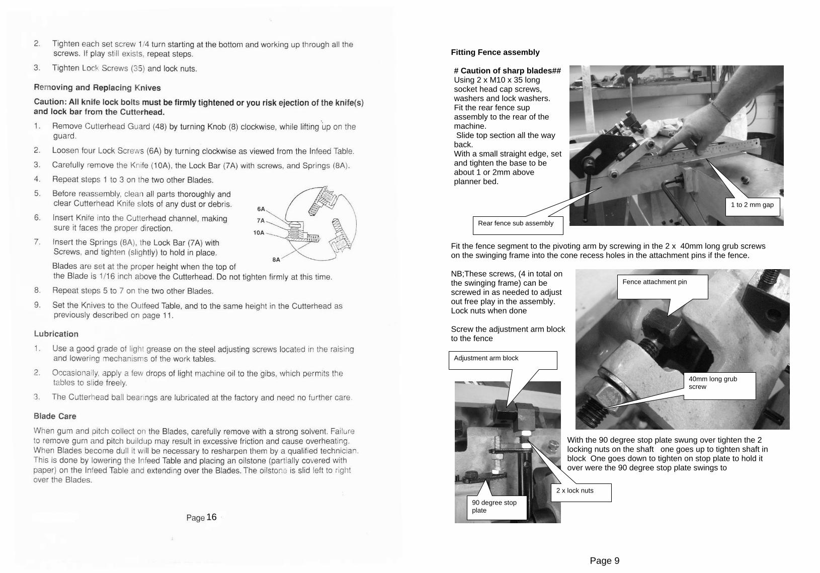
Fitting Fence assembly
# Caution of sharp blades## Using 2 x M10 x 35 long socket head cap screws, washers and lock washers. Fit the rear fence sup assembly to the rear of the machine. Slide top section all the way back. With a small straight edge, set and tighten the base to be about 1 or 2mm above planner bed.
Fit the fence segment to the pivoting arm by screwing in the 2 x 40mm long grub screws on the swinging frame into the cone recess holes in the attachment pins if the fence.
NB;These screws, (4 in total on the swinging frame) can be screwed in as needed to adjust out free play in the assembly. Lock nuts when done
Screw the adjustment arm block to the fence
With the 90 degree stop plate swung over tighten the 2 locking nuts on the shaft one goes up to tighten shaft in block One goes down to tighten on stop plate to hold it over were the 90 degree stop plate swings to
Rear fence sub assembly
1 to 2 mm gap
40mm long grub screw
Fence attachment pin
Adjustment arm block
2 x lock nuts
90 degree stop plate
Page 9
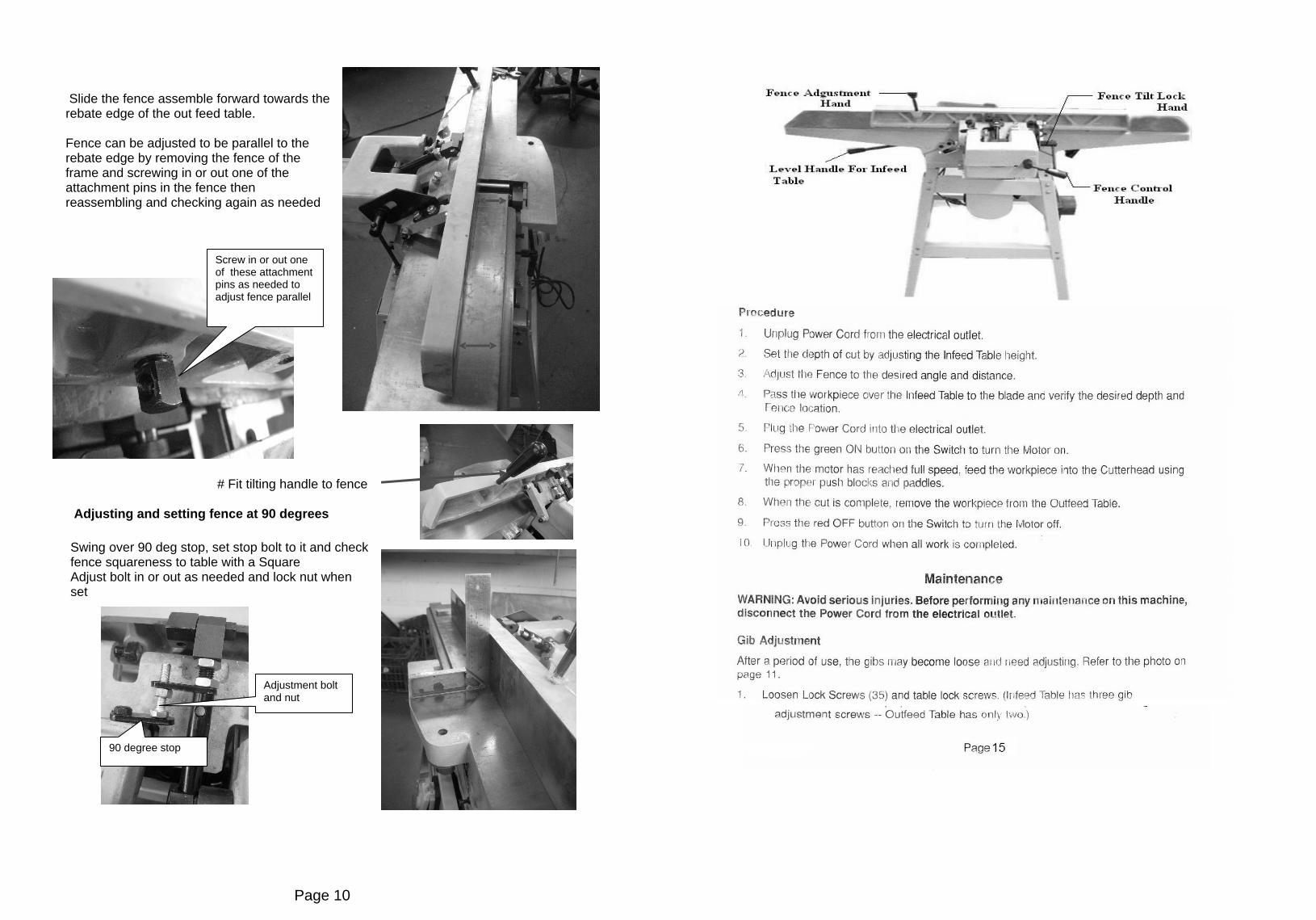
Slide the fence assemble forward towards the rebate edge of the out feed table.
Fence can be adjusted to be parallel to the rebate edge by removing the fence of the frame and screwing in or out one of the attachment pins in the fence then reassembling and checking again as needed
# Fit tilting handle to fence
Adjusting and setting fence at 90 degrees
Swing over 90 deg stop, set stop bolt to it and check fence squareness to table with a Square Adjust bolt in or out as needed and lock nut when set
Screw in or out one of these attachment pins as needed to adjust fence parallel
90 degree stop
Adjustment bolt and nut
Page 10

Adjusting and setting fence at 130 degrees
Swing the 90 degree stop out of the way. Tilt the fence all the way back
Using 2 Squares, one with a 45 degree angle or a compound set square, Adjust the 130 degree stop bolt to get fence to 130 degrees, when set lock the bolt with the lock nut .
Fitting Cutter guard
Turn the spring knob about one and a half turns counter clockwise and hold in place
Insert the cutter head guard post into the hole in the top of the table, making sure the spring engages in the slot in the guard post
Check proper operation Pull the guard out away from the fence horizontally, then let go. It should spring back to the fence If it does not spring back with force reset spring tension and check again
130 degree stop and lock nut
Spring knob
Cutter guard
Page 11

Fitting lower dust chute
Fit the lower dust chute plate and extraction port The plate has 2 tabs these sit in the top side slots of the dust chute and then slide plate up. Fit the plastic extraction cute over the bottom and secure both with the 2 x knurled finger screws supplied
Table adjustment
# Check table slides are adjusted correctly There are 2 slide keys. One on each table.
These allow the table to be set flat to each other and to stop the infeed table falling down by itself during use.
They adjustment screws (4 off) need to be set. Firstly undo the locking nut on the screw. Then turn the
screw all the way in and undo ¼ of a turn. Lock the nut Test table still moves freely. The infeed table should not be too loose as it will fall lower during operation if it is.
# Connect a dust extractor
# Your machine is now ready to use.
Knurled finger screw
Adjustment screw and lock nut
Page 12
13


![MRS. OLIVIA ADENDORFF...fall 2013 down the isle greece is the word for highland park bride [ p. 4 ] mrs. olivia adendorff professionals ready to help [ p. 42 ] track stars raced to](https://img.pdfslide.us/doc/110x75/5f4d15ed513c42317e48a86b/mrs-olivia-adendorff-fall-2013-down-the-isle-greece-is-the-word-for-highland.jpg)