Embed Size (px)
Citation preview
Operating InstructionsEdition 09/2007 - Revision 05
Order no.: A5E00730100
SFIDK.PS.022.Q5.02 A5E00730100
SITRANS F USUltrasonic flowmeter type SITRANS FUS380
Ultrasonic flowmeter type SITRANS FUE380(type-approved for heat metering)
[
s
Technical Documentation (handbooks, instructions, manuals etc.) for the complete productrange SITRANS F can be found on the internet/intranet via the following link:
English: http://www4.ad.siemens.de/WW/view/en/10806951/133300
]
2 SFIDK.PS.022.Q5.02
Introduction 1
General safety instructions 2
Description 3
Installation 4
Electrical connection 5
Operation 6
Troubleshooting 7
Sealing 8
Technical data 9
Ordering 10
Appendix 11
3SFIDK.PS.022.Q5.02
Table of contents
1 Introduction . . . . . . . . . . . . . . . . . . . . . . . . . . . . . . . . . . . . . . . . . . . . . . . . . . . . . . . . . . . . . . . . . . . . . 41.1 Preface . . . . . . . . . . . . . . . . . . . . . . . . . . . . . . . . . . . . . . . . . . . . . . . . . . . . . . . . . . . . . . . . . . . . . . . . 4
2. General safety instructions . . . . . . . . . . . . . . . . . . . . . . . . . . . . . . . . . . . . . . . . . . . . . . . . . . . . . . . . . 42.1 Safety notes . . . . . . . . . . . . . . . . . . . . . . . . . . . . . . . . . . . . . . . . . . . . . . . . . . . . . . . . . . . . . . . . . . . . 42.2 Manufacturer’s design and safety statement . . . . . . . . . . . . . . . . . . . . . . . . . . . . . . . . . . . . . . . . . . . 4
3. Description . . . . . . . . . . . . . . . . . . . . . . . . . . . . . . . . . . . . . . . . . . . . . . . . . . . . . . . . . . . . . . . . . . . . . 63.1 Product description . . . . . . . . . . . . . . . . . . . . . . . . . . . . . . . . . . . . . . . . . . . . . . . . . . . . . . . . . . . . . . . 63.2 Service . . . . . . . . . . . . . . . . . . . . . . . . . . . . . . . . . . . . . . . . . . . . . . . . . . . . . . . . . . . . . . . . . . . . . . . . 6
4. Installation . . . . . . . . . . . . . . . . . . . . . . . . . . . . . . . . . . . . . . . . . . . . . . . . . . . . . . . . . . . . . . . . . . . . . 74.1 Installation of sensor compact/remote versions . . . . . . . . . . . . . . . . . . . . . . . . . . . . . . . . . . . . . . . . . 74.2 Installation of transmitter compact/remote versions . . . . . . . . . . . . . . . . . . . . . . . . . . . . . . . . . . . . . . 94.2.1 General information . . . . . . . . . . . . . . . . . . . . . . . . . . . . . . . . . . . . . . . . . . . . . . . . . . . . . . . . . . . . . . 94.2.2 Insulation . . . . . . . . . . . . . . . . . . . . . . . . . . . . . . . . . . . . . . . . . . . . . . . . . . . . . . . . . . . . . . . . . . . . . . 94.2.3 Mains powered version . . . . . . . . . . . . . . . . . . . . . . . . . . . . . . . . . . . . . . . . . . . . . . . . . . . . . . . . . . . 94.2.4 Wiring diagram for mains power supply, pulse output . . . . . . . . . . . . . . . . . . . . . . . . . . . . . . . . . . . . 94.2.5 Mains powered units with back-up battery . . . . . . . . . . . . . . . . . . . . . . . . . . . . . . . . . . . . . . . . . . . . 104.3 Battery powered version . . . . . . . . . . . . . . . . . . . . . . . . . . . . . . . . . . . . . . . . . . . . . . . . . . . . . . . . . 114.4 Installation of the transmitter, remote version . . . . . . . . . . . . . . . . . . . . . . . . . . . . . . . . . . . . . . . . . . 124.4.1 Installation of wall/pipe bracket . . . . . . . . . . . . . . . . . . . . . . . . . . . . . . . . . . . . . . . . . . . . . . . . . . . . 124.4.2 Connection of transducer cables . . . . . . . . . . . . . . . . . . . . . . . . . . . . . . . . . . . . . . . . . . . . . . . . . . . 124.4.3 Transducer connection scheme . . . . . . . . . . . . . . . . . . . . . . . . . . . . . . . . . . . . . . . . . . . . . . . . . . . . 134.4.4 Wiring diagram, base of connection board . . . . . . . . . . . . . . . . . . . . . . . . . . . . . . . . . . . . . . . . . . . 13
5. Electrical connection . . . . . . . . . . . . . . . . . . . . . . . . . . . . . . . . . . . . . . . . . . . . . . . . . . . . . . . . . . . . 145.1 Pulse output A and B setting . . . . . . . . . . . . . . . . . . . . . . . . . . . . . . . . . . . . . . . . . . . . . . . . . . . . . . 145.1.1 FUE380 preset pulse output A settings dedicated to energy calculator type SITRANS FUE950 . . 145.1.2 FUS380 and FUE380 preset output B settings . . . . . . . . . . . . . . . . . . . . . . . . . . . . . . . . . . . . . . . . 155.1.3 Wiring diagram for connection to energy calculator type SITRANS FUE950 . . . . . . . . . . . . . . . . . 16
6. Operation . . . . . . . . . . . . . . . . . . . . . . . . . . . . . . . . . . . . . . . . . . . . . . . . . . . . . . . . . . . . . . . . . . . . . 176.1 Flowmeter operation via key and display . . . . . . . . . . . . . . . . . . . . . . . . . . . . . . . . . . . . . . . . . . . . 176.2 Operator menu . . . . . . . . . . . . . . . . . . . . . . . . . . . . . . . . . . . . . . . . . . . . . . . . . . . . . . . . . . . . . . . . . 186.3 Information symbols . . . . . . . . . . . . . . . . . . . . . . . . . . . . . . . . . . . . . . . . . . . . . . . . . . . . . . . . . . . . . 19
7. Troubleshooting . . . . . . . . . . . . . . . . . . . . . . . . . . . . . . . . . . . . . . . . . . . . . . . . . . . . . . . . . . . . . . . . 197.1 Alarm code . . . . . . . . . . . . . . . . . . . . . . . . . . . . . . . . . . . . . . . . . . . . . . . . . . . . . . . . . . . . . . . . . . . . 19
8. Sealing . . . . . . . . . . . . . . . . . . . . . . . . . . . . . . . . . . . . . . . . . . . . . . . . . . . . . . . . . . . . . . . . . . . . . . . 208.1 User sealing of the SITRANS FUE380 . . . . . . . . . . . . . . . . . . . . . . . . . . . . . . . . . . . . . . . . . . . . . . . 208.2 Verification sealing of the SITRANS FUE380 . . . . . . . . . . . . . . . . . . . . . . . . . . . . . . . . . . . . . . . . . 20
9. Technical data . . . . . . . . . . . . . . . . . . . . . . . . . . . . . . . . . . . . . . . . . . . . . . . . . . . . . . . . . . . . . . . . . 219.1 Technical data SITRANS FUS380 and FUE380 . . . . . . . . . . . . . . . . . . . . . . . . . . . . . . . . . . . . . . . 219.2 Dimensional drawings for FUS380 and FUE380 . . . . . . . . . . . . . . . . . . . . . . . . . . . . . . . . . . . . . . 229.2.1 Pipe dimensions for FUS380 and FUE380 . . . . . . . . . . . . . . . . . . . . . . . . . . . . . . . . . . . . . . . . . . . 22
10. Ordering . . . . . . . . . . . . . . . . . . . . . . . . . . . . . . . . . . . . . . . . . . . . . . . . . . . . . . . . . . . . . . . . . . . . . . 2410.1 FUS380 selection and ordering data . . . . . . . . . . . . . . . . . . . . . . . . . . . . . . . . . . . . . . . . . . . . . . . . 2410.2 FUE380 (type approved) selection and ordering data . . . . . . . . . . . . . . . . . . . . . . . . . . . . . . . . . . 2610.3 Spare parts for FUS380 and FUE380 . . . . . . . . . . . . . . . . . . . . . . . . . . . . . . . . . . . . . . . . . . . . . . . 28
11. Appendix . . . . . . . . . . . . . . . . . . . . . . . . . . . . . . . . . . . . . . . . . . . . . . . . . . . . . . . . . . . . . . . . . . . . . 2911.1 EC Declaration of Conformity . . . . . . . . . . . . . . . . . . . . . . . . . . . . . . . . . . . . . . . . . . . . . . . . . . . . . . 29
4 SFIDK.PS.022.Q5.02
1.1 Preface
Introduction 1
These instructions contain all the information required to commission and use the SITRANS FUSultrasonic flowmeter types FUS380 and the type-approved flowmeter FUE380 for heat meteringsystems.
These instructions are intended to assist personnel performing mechanical installation, electricalconnection and commissioning of the device, as well as service and maintenance engineers.
General safety instructions 2
2.1 Safety notesFor safety reasons it is important that the following points, especially those marked with a warningsign, are read and understood before the system is installed:
• Installation, connection, commissioning and service must be carried out by personnel whoare qualified and authorized to do so.
• It is very important for any person working with the equipment to read and understand theinstructions and directions provided in this manual and follow instructions and directionsbefore using the equipment.
• Only personnel authorized and trained by the owner of the equipment may operate theequipment.
• Installation personnel must ensure that the measuring system is correctly connected inaccordance with the connection diagram.
• For applications involving high working pressures or media that can be dangerous topeople, surroundings, equipment or other in the event of pipe fracture, Siemens recommendstaking precautions such as special placement, shielding or installation of a safety guard orsafety valve prior to installation of the sensor.
• Repair and service may be performed by approved Siemens Flow Instruments personnelonly.
2.2 Manufacturer’s design and safety statement• Responsibility for the choice of flowmeter pipe material as regards abrasion and corrosion
resistance lies with the purchaser. The effect of any change in process medium duringoperation of the meter should be taken into account. Incorrect selection of flowmeter pipematerial could lead to failure of the flowmeter.
• Stresses and loading caused by earthquakes, traffic, high winds and fire damage are not takeninto account during flowmeter design.
5SFIDK.PS.022.Q5.02
• Do not install the flowmeter such that it acts as a focus for pipeline stresses. External loadingis not taken into account during flowmeter design.
• Please aware about the risk of installing the sensor in a highly vibrating environment.Parts may shake loose and the complete system must be monitored in that case.
• Flanges and joints as well as related pressure/temperature (p/t) classification has beendescribed in EN 1092-1. See ferrite steel group 1E1: table 15.
• During operation do not exceed the pressure and/or temperature ratings indicated on the datalabel or in this Operating Manual.
• It is recommended that all installations include an appropriate safety valve and adequatemeans for draining.
• Under the „Pressure Equipment Directive“ (PED), this product is a presssure accessory andnot approved for use as a safety accessory, as defined by the PED.
• DANGERDo not unscrew the transducers during pipe operation (especially for DN 50 ... DN 80).
Battery operation:
• When battery operated, SITRANS FUS380 and FUE380 is not covered by the „Low VoltageDirective“ (LVD). Hence, an installation can be considered in conformance with LVD, onlywhen the SITRANS FUS380 /FUE380 is connected to equipment conforming to LVD.
• Lithium batteries are primary power sources with high energy content. They are designed tomeet the highest possible safety standard. They may, however, present a potential hazard ifthey are abused electrically or mechanically. This is in most circumstances associated withthe generation of excessive heat, where increased internal pressure may cause the cell torupture.
Thus the following basic precautions should be observed when handling and using lithiumbatteries:- Do not short-circuit, recharge, overcharge or connect with false polarity.- Do not expose to temperature beyond the specified temperature range or incinerate the
battery.- Do not crush, puncture or open cells or disassemble battery packs.- Do not weld or solder to the body of the battery.- Do not expose contents to water.
• Lithium batteries are regulated under United Nations Model Regulations on Transport ofDangerous goods, UN document ST/SGAC.10-1,12th revised edition, 2001. UN no. 3091 class9 covers lithium batteries packed with or inside the equipment. UN no. 3090 class 9 coverstransportation of batteries on their own.Thus the following basic precautions should be followed when transporting lithium batteries:- Transport only in special packaging with special labels and transportation documents.- Exercise caution in handling, transportation and packaging in order to prevent short
circuiting of the batteries.- The gross mass of the package is limited according to the type of transportation.
In general, a gross mass below 5 kg is acceptable for all forms of transportation.
• Remove the battery from transmitter before returning the flowmeter to Siemens for service orwarranty claim.
6 SFIDK.PS.022.Q5.02
Description 3
3.1 Product descriptionThe 2-track ultrasonic flowmeter SITRANS FUS380 and approved SITRANS FUE380 comes asbattery or mains powered and is designed to measure water flow in district heating plants, localstations, substations, chiller plants and other general water applications including treated wastewater.
The SITRANS FUS flowmeter is available in the following variants:
• FUS380: A universal flowmeter with selectable settings.• FUE380: A type-approved flowmeter dedicated to measure flow in a heating system.
SITRANS FUE380 is approved according to heat meter standards EN 1434class 2, OIML R75 class 2 and MID.FUE380 may be marked „neutral“ or have a country-specific approval label,depending on selection of flowmeter setup when ordering.
Both flowmeter types SITRANS FUS380 and FUE380 are available in either compact or remoteversions and electrical wiring and operation are identical for both types. The maximum permissibledistance between sensor and transmitter is 30 meters.
The flowmeter comes as a transmitter part FUS080 and a sensor part FUS300. This two partscan be only ordered together as a flowmeter system type FUS380 or FUE380. For FUS380 a sparepart transmitter can be ordered separate (see FI01 catalogue). For FUE380 is this not allowedaccording the approvals. For both systems the sensor part cannot be ordered without atransmitter.
In FUS380 parameters and pulse output are preset from factory and protected via software lock.A software tool is required to change parameters.
In FUE380 - metrological parameters and pulse output are preset from factory and protected viahardware lock and sealings to avoid manipulation.
No settings of installation are required as all parameters are set from factory (plug and play).
Maximum temperature compact for DN 50 ... 1200 sensors 2 ... 120 ºC (35,6 ... 248 ºF).
Maximum temperature remote version DN 100 ... 1200 steel sensors 2 ... 200 ºC(35,6 ... 392 ºF) and for DN 50 ... 80 red brass sensors 2 ... 150 ºC (35,6 ... 302 ºF).
Accessories for correct pipeline assembly and use of flanges gaskets are not Siemens FlowInstruments A/S responsibility.
3.2 ServiceIn order to locate and diagnose failures, a software tool for diagnosis and re-programming ofoutputs is available. Failure information is available on the display. Failures are stored in memory,and can be accessed via the infra-red communication port.
(Software for diagnosis and setting of parameters is available from Siemens Automation andDrives, Process Instrumentation and Analytics).
7SFIDK.PS.022.Q5.02
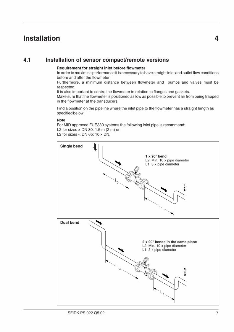
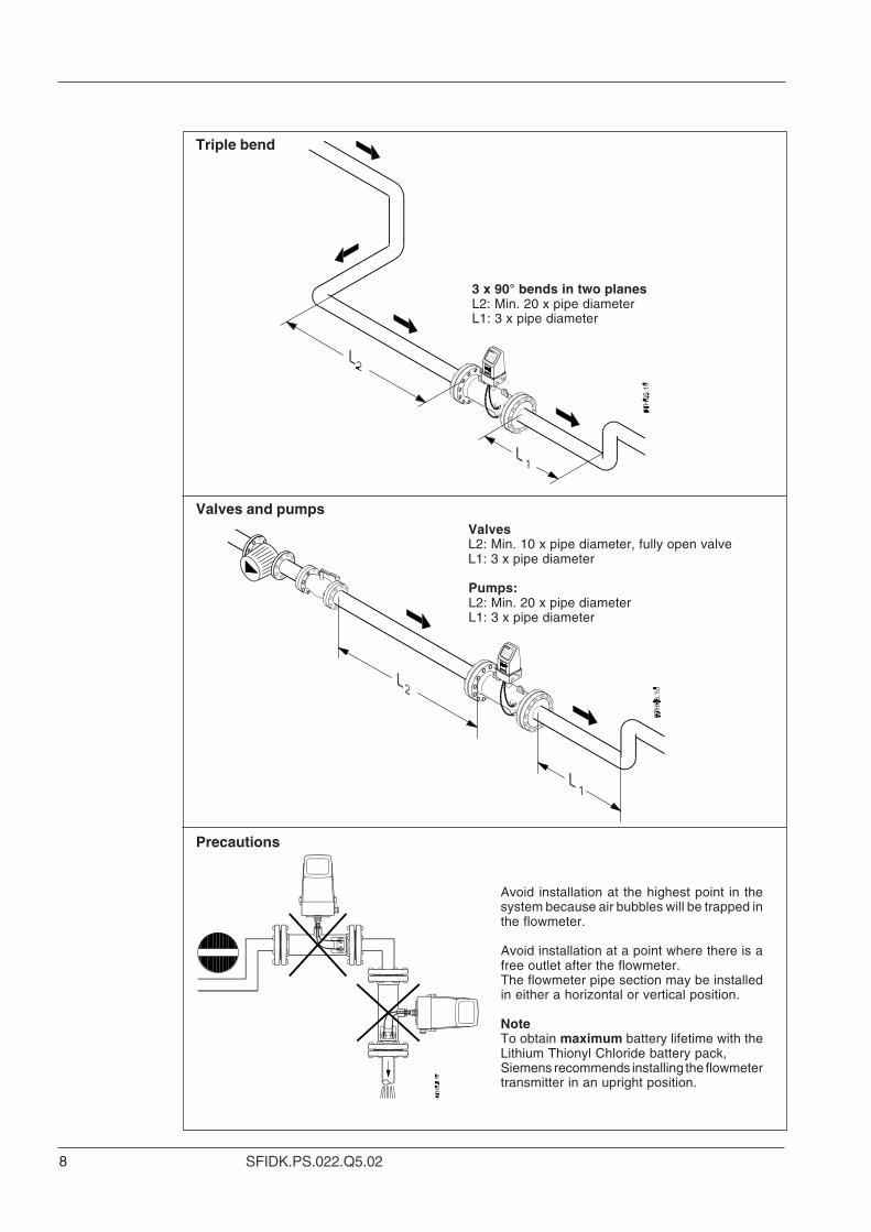
Single bend
Dual bend
1 x 90° bendL2: Min. 10 x pipe diameterL1: 3 x pipe diameter
2 x 90° bends in the same planeL2: Min. 10 x pipe diameterL1: 3 x pipe diameter
4.1 Installation of sensor compact/remote versionsRequirement for straight inlet before flowmeterIn order to maximise performance it is necessary to have straight inlet and outlet flow conditionsbefore and after the flowmeter.Furthermore, a minimum distance between flowmeter and pumps and valves must berespected.It is also important to centre the flowmeter in relation to flanges and gaskets.Make sure that the flowmeter is positioned as low as possible to prevent air from being trappedin the flowmeter at the transducers.
Find a position on the pipeline where the inlet pipe to the flowmeter has a straight length asspecified below.
NoteFor MID approved FUE380 systems the following inlet pipe is recommend:L2 for sizes > DN 80: 1.5 m (2 m) orL2 for sizes < DN 65: 10 x DN.
Installation 4
8 SFIDK.PS.022.Q5.02
Valves and pumps
Precautions
Avoid installation at the highest point in thesystem because air bubbles will be trapped inthe flowmeter.
Avoid installation at a point where there is afree outlet after the flowmeter.The flowmeter pipe section may be installedin either a horizontal or vertical position.
NoteTo obtain maximum battery lifetime with theLithium Thionyl Chloride battery pack,Siemens recommends installing the flowmetertransmitter in an upright position.
3 x 90° bends in two planesL2: Min. 20 x pipe diameterL1: 3 x pipe diameter
ValvesL2: Min. 10 x pipe diameter, fully open valveL1: 3 x pipe diameter
Pumps:L2: Min. 20 x pipe diameterL1: 3 x pipe diameter
Triple bend
9SFIDK.PS.022.Q5.02
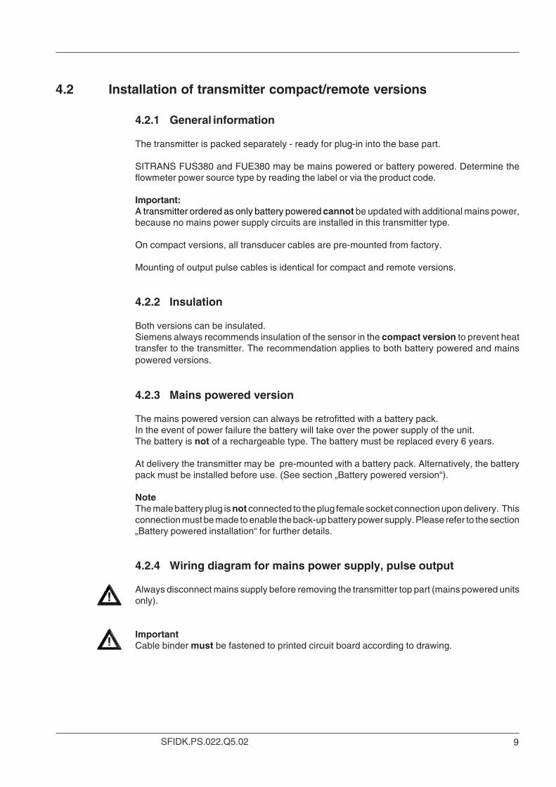
4.2 Installation of transmitter compact/remote versions
4.2.1 General information
The transmitter is packed separately - ready for plug-in into the base part.
SITRANS FUS380 and FUE380 may be mains powered or battery powered. Determine theflowmeter power source type by reading the label or via the product code.
Important:A transmitter ordered as only battery powered cannot be updated with additional mains power,because no mains power supply circuits are installed in this transmitter type.
On compact versions, all transducer cables are pre-mounted from factory.
Mounting of output pulse cables is identical for compact and remote versions.
4.2.2 Insulation
Both versions can be insulated.Siemens always recommends insulation of the sensor in the compact version to prevent heattransfer to the transmitter. The recommendation applies to both battery powered and mainspowered versions.
4.2.3 Mains powered version
The mains powered version can always be retrofitted with a battery pack.In the event of power failure the battery will take over the power supply of the unit.The battery is not of a rechargeable type. The battery must be replaced every 6 years.
At delivery the transmitter may be pre-mounted with a battery pack. Alternatively, the batterypack must be installed before use. (See section „Battery powered version“).
NoteThe male battery plug is not connected to the plug female socket connection upon delivery. Thisconnection must be made to enable the back-up battery power supply. Please refer to the section„Battery powered installation“ for further details.
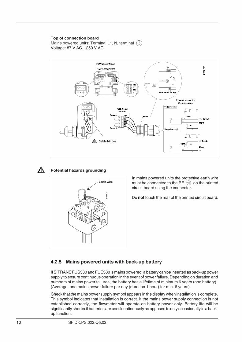
4.2.4 Wiring diagram for mains power supply, pulse output
Always disconnect mains supply before removing the transmitter top part (mains powered unitsonly).
ImportantCable binder must be fastened to printed circuit board according to drawing.
10 SFIDK.PS.022.Q5.02
Cable binder
Potential hazards grounding
Earth wireIn mains powered units the protective earth wiremust be connected to the PE on the printedcircuit board using the connector.
Do not touch the rear of the printed circuit board.
4.2.5 Mains powered units with back-up battery
If SITRANS FUS380 and FUE380 is mains powered, a battery can be inserted as back-up powersupply to ensure continuous operation in the event of power failure. Depending on duration andnumbers of mains power failures, the battery has a lifetime of minimum 6 years (one battery).(Average: one mains power failure per day (duration 1 hour) for min. 6 years).
Check that the mains power supply symbol appears in the display when installation is complete.This symbol indicates that installation is correct. If the mains power supply connection is notestablished correctly, the flowmeter will operate on battery power only. Battery life will besignificantly shorter if batteries are used continuously as opposed to only occasionally in a back-up function.
Top of connection boardMains powered units: Terminal L1, N, terminalVoltage: 87 V AC…250 V AC
11SFIDK.PS.022.Q5.02
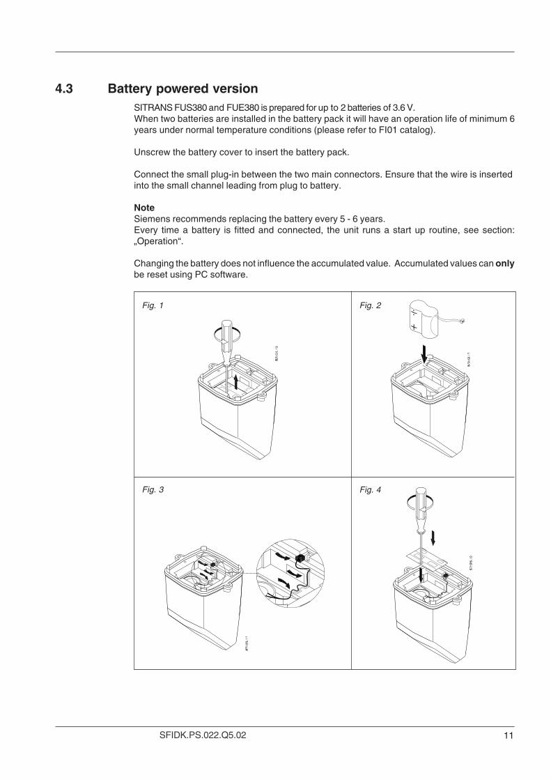
SITRANS FUS380 and FUE380 is prepared for up to 2 batteries of 3.6 V.When two batteries are installed in the battery pack it will have an operation life of minimum 6years under normal temperature conditions (please refer to FI01 catalog).
Unscrew the battery cover to insert the battery pack.
Connect the small plug-in between the two main connectors. Ensure that the wire is insertedinto the small channel leading from plug to battery.
NoteSiemens recommends replacing the battery every 5 - 6 years.Every time a battery is fitted and connected, the unit runs a start up routine, see section:„Operation“.
Changing the battery does not influence the accumulated value. Accumulated values can onlybe reset using PC software.
4.3 Battery powered version
Fig. 1 Fig. 2
Fig. 3 Fig. 4
12 SFIDK.PS.022.Q5.02
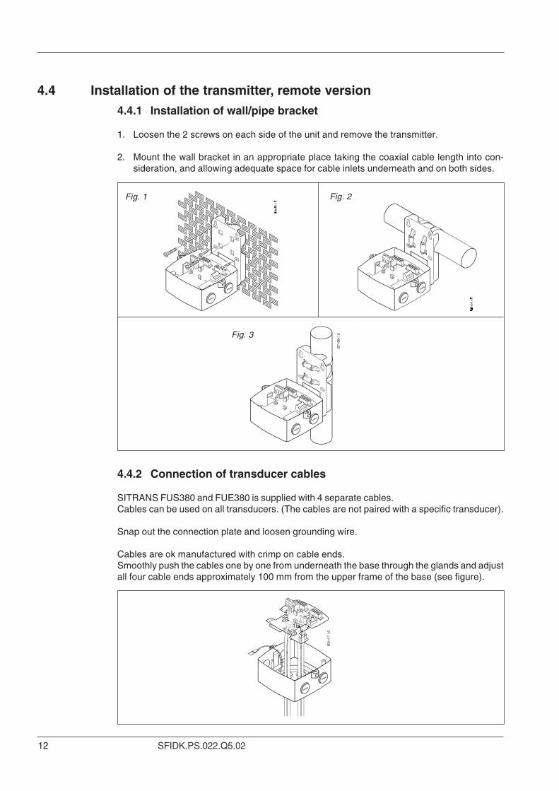
4.4.2 Connection of transducer cables
SITRANS FUS380 and FUE380 is supplied with 4 separate cables.Cables can be used on all transducers. (The cables are not paired with a specific transducer).
Snap out the connection plate and loosen grounding wire.
Cables are ok manufactured with crimp on cable ends.Smoothly push the cables one by one from underneath the base through the glands and adjustall four cable ends approximately 100 mm from the upper frame of the base (see figure).
4.4.1 Installation of wall/pipe bracket
1. Loosen the 2 screws on each side of the unit and remove the transmitter.
2. Mount the wall bracket in an appropriate place taking the coaxial cable length into con-sideration, and allowing adequate space for cable inlets underneath and on both sides.
4.4 Installation of the transmitter, remote version
Fig. 2
Fig. 3
Fig. 1
13SFIDK.PS.022.Q5.02
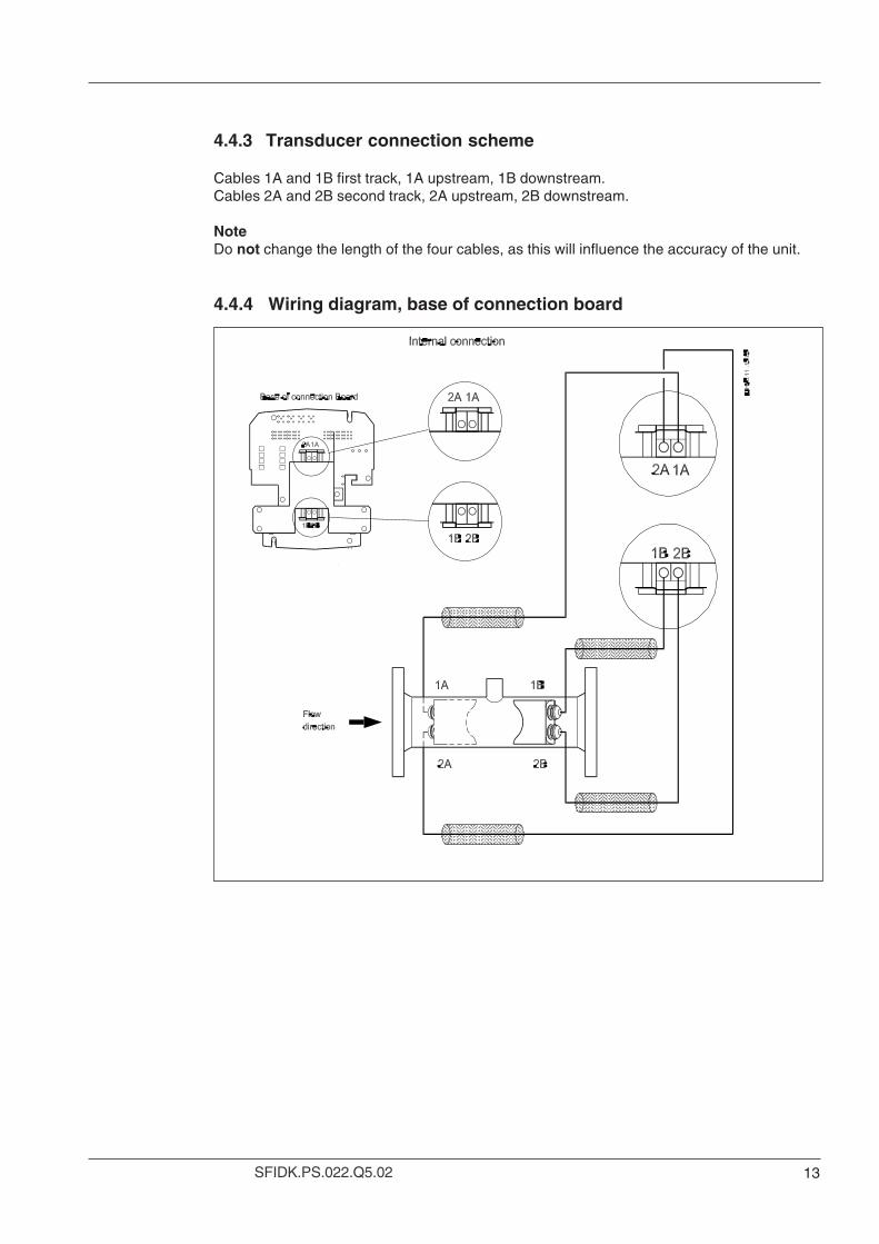
4.4.4 Wiring diagram, base of connection board
4.4.3 Transducer connection scheme
Cables 1A and 1B first track, 1A upstream, 1B downstream.Cables 2A and 2B second track, 2A upstream, 2B downstream.
NoteDo not change the length of the four cables, as this will influence the accuracy of the unit.
14 SFIDK.PS.022.Q5.02
Install the pulse cable through the glands, before pushing the printed circuit board back intoplace in the base part.For compact version, install the pulse cables and power supply cable through the gland withoutremove the printed circuit board.
For FUS380 and FUE380 the pulse output A and B settings are depending form the ordering:Normal factory setting see following table. The settings for FUS380 can be read out and changedwith a PC, the software SIMATIC PDM (Process device manager) and the IrDa optical interface(see accessories for FUS380 in FI01 catalogue). The approved FUE380 settings cannot bechanged according the approval requirements, but it can be read out per PDM.
Electrical connection 5
5.1 Pulse output A and B setting
FUS380 FUE380
Output A Forward / reverse Preset: Forward
Output B Preset: Alarm Preset: Alarm
Output B, function Reverse pulse, alarm, call-up Preset: Alarm
Pulse value A & B 0.1 l/p; 0.25 l/p; 0.5 l/p; 1 l/p; 2.5 l/p; Preset: See scheme to FUE380.(depenting on DN value) 10 l/p; 25 l/p; 50 l/p; 100 l/p; 250 l/p;
500 l/p; 1 m3/p; 2.5 m3/p; Settings typically for5 m3/p; 10 m3/p; 25 m3/p; SITRANS FUE950 energy50 m3/p; 100 m3/p; calculator.250 m3/p; 500 m3/p;1000 m3/p
Pulse with 5; 10; 20; 50; 100; 200; 500 ms Preset: 5 ms
5.1.1 FUE380 preset pulse output A settings dedicated to energycalculator type SITRANS FUE950
Output A, terminals 56/57:Pulse rate can be seen on the transmitter side label and must correspond to the pulse settingof the energy calculator type.Factory pre-settings SITRANS FUE380. (Pulse width 5 ms).
DN Pulse setting (liter/pulse )50 165 180 2.5
100 2.5125 2.5150 10200 10250 10300 50350 50400 50500 100600 100700 100800 100900 1001000 1001200 100
15SFIDK.PS.022.Q5.02
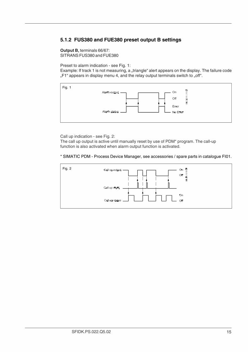
5.1.2 FUS380 and FUE380 preset output B settings
Output B, terminals 66/67:SITRANS FUS380 and FUE380
Preset to alarm indication - see Fig. 1:Example: If track 1 is not measuring, a „triangle“ alert appears on the display. The failure code„F1“ appears in display menu 4, and the relay output terminals switch to „off“.
Fig. 1
Call up indication - see Fig. 2:The call up output is active until manually reset by use of PDM* program. The call-upfunction is also activated when alarm output function is activated.
* SIMATIC PDM - Process Device Manager, see accessories / spare parts in catalogue FI01.
Fig. 2
16 SFIDK.PS.022.Q5.02
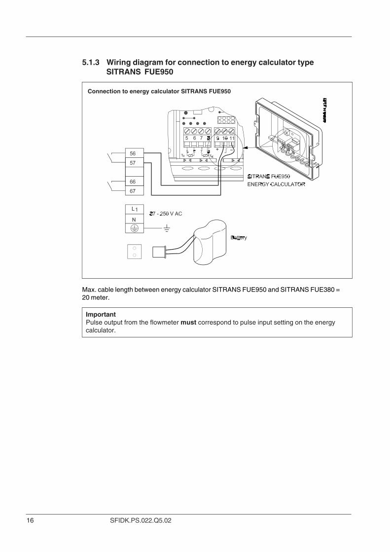
Max. cable length between energy calculator SITRANS FUE950 and SITRANS FUE380 =20 meter.
ImportantPulse output from the flowmeter must correspond to pulse input setting on the energycalculator.
5.1.3 Wiring diagram for connection to energy calculator typeSITRANS FUE950
Connection to energy calculator SITRANS FUE950
17SFIDK.PS.022.Q5.02
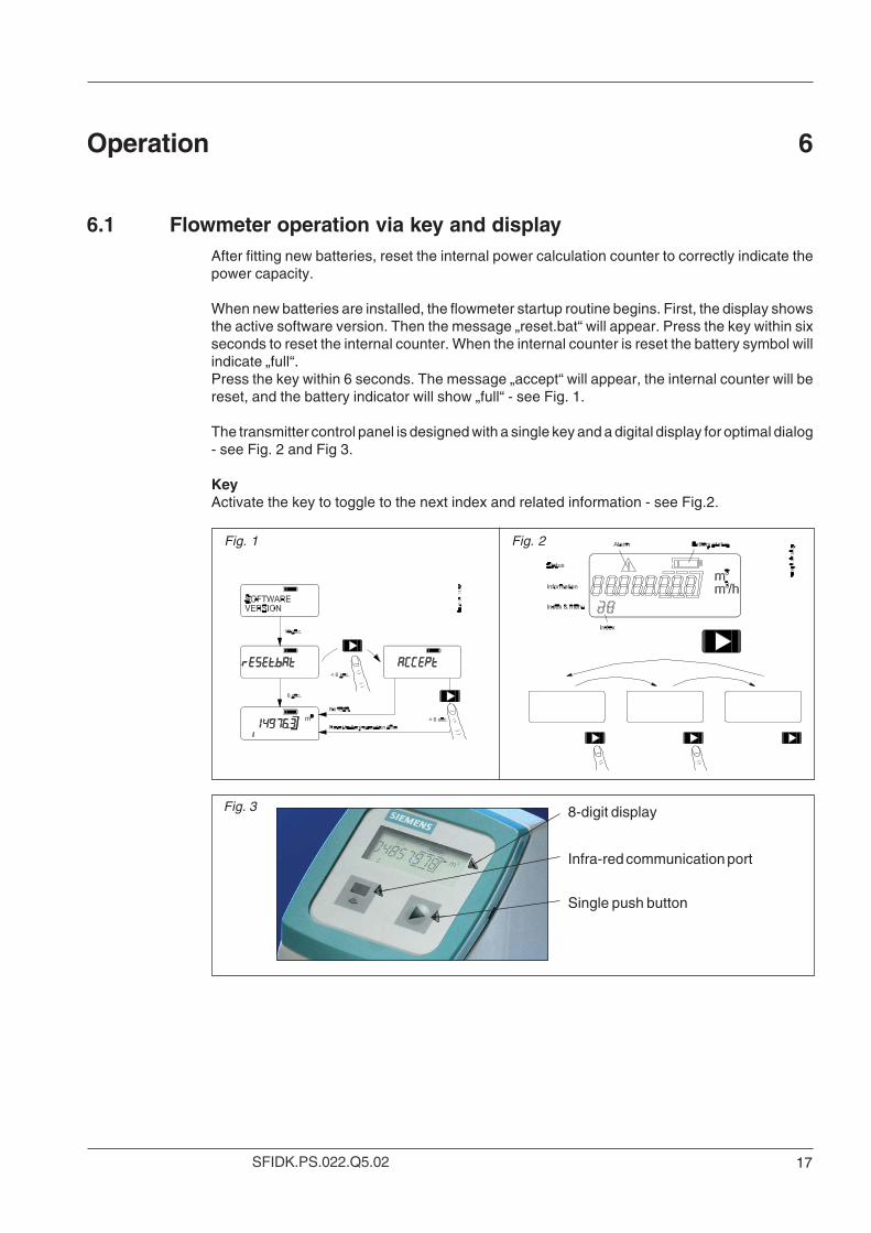
After fitting new batteries, reset the internal power calculation counter to correctly indicate thepower capacity.
When new batteries are installed, the flowmeter startup routine begins. First, the display showsthe active software version. Then the message „reset.bat“ will appear. Press the key within sixseconds to reset the internal counter. When the internal counter is reset the battery symbol willindicate „full“.Press the key within 6 seconds. The message „accept“ will appear, the internal counter will bereset, and the battery indicator will show „full“ - see Fig. 1.
The transmitter control panel is designed with a single key and a digital display for optimal dialog- see Fig. 2 and Fig 3.
KeyActivate the key to toggle to the next index and related information - see Fig.2.
Operation 6
6.1 Flowmeter operation via key and display
8-digit display
Infra-red communication port
Single push button
Fig. 1 Fig. 2
Fig. 3
18 SFIDK.PS.022.Q5.02
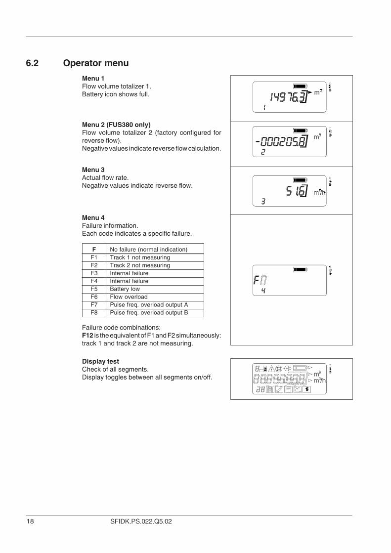
F No failure (normal indication)F1 Track 1 not measuringF2 Track 2 not measuringF3 Internal failureF4 Internal failureF5 Battery lowF6 Flow overloadF7 Pulse freq. overload output AF8 Pulse freq. overload output B
Menu 4Failure information.Each code indicates a specific failure.
Menu 1Flow volume totalizer 1.Battery icon shows full.
Menu 2 (FUS380 only)Flow volume totalizer 2 (factory configured forreverse flow).Negative values indicate reverse flow calculation.
Menu 3Actual flow rate.Negative values indicate reverse flow.
Display testCheck of all segments.Display toggles between all segments on/off.
6.2 Operator menu
Failure code combinations:F12 is the equivalent of F1 and F2 simultaneously:track 1 and track 2 are not measuring.
19SFIDK.PS.022.Q5.02
Alarm code Failure RemedyBlank display Battery plug not connected, or battery Check flowmeter version. Battery version not
empty, mains power interrupted able to run on mains powerBattery version: Replace battery pack
F1 Track 1 (upper track) not measuring No water in upper part of pipe and/or cables ortransducer 1A or 1B defect
F2 Track 2 (lower track) not measuring No water in lower part of pipe and/or cables ortranducers for 2A or 2B defect
F3 Internal software failure Contact supplierF4 Internal software failure Contact supplierF5 Battery charge below preset limitation Replace battery packF6 Flow exceeds preset flow rate Water flow in pipe too fast
in unit (max. speed 10 m/s)F7 Pulse output A overflow Pulse output exceeds 100 HzF8 Pulse output B overflow Pulse output exceeds 100 Hz
Example:Failure information in display F12. This indicates a combination of failure codes F1 and F2.
Diagnosis:No water in pipe, or track 1 and 2 cables defect, or transducers defect.
Troubleshooting 7
7.1 Alarm code
There are two symbols for battery charge status.The „battery full“ symbol indicates the batterycharge is above the warning level (6-year hourcounter).The „battery low“ symbol indicates that the batterycharge is below the warning level and the batteryshould be replaced. The battery low symbolindicates only that the battery charge is below apre-set level, not that the charge is zero. Flowmeasurement continues uninterrupted when thebattery low symbol appears, until battery iscompletely drained.
The status information symbols show the actualstatus of important flowmeter elements.The warning symbol appears when the ultrasonicsensors do not measure or when a failure occursaccording to menu 4.The warning symbol disappears when the problemis rectified.The mains power supply symbol appears whenmains power is connected to the transmitter.
6.3 Information symbols
20 SFIDK.PS.022.Q5.02
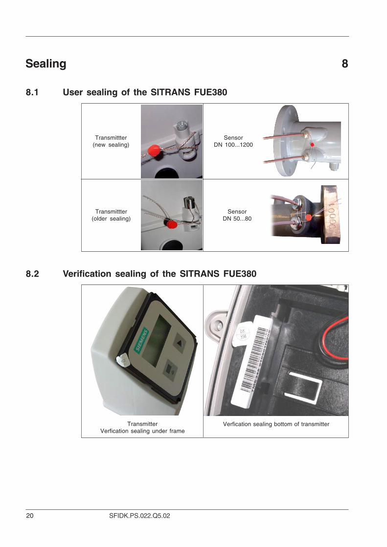
Sealing 8
8.1 User sealing of the SITRANS FUE380
SensorDN 100...1200
8.2 Verification sealing of the SITRANS FUE380
Verfication sealing bottom of transmitter
Transmittter(older sealing)
TransmitterVerfication sealing under frame
Transmittter(new sealing)
SensorDN 50...80
21SFIDK.PS.022.Q5.02
Description SpecificationTransmitter FUS080Enclosure IP67 according to EN 60529 and DIN 40050 (NEMA 4X/6)Ambient temperature 0 °C …60 °C (32 °F…. 140 °F)Storage temperature −35 °C…85 °C (−40 °F…185 °F)Installation Cable max. 5, 10, 20, 30 m (16.4, 33, 65, 90 ft) from sensorMechanical vibration 2 g, 1…800 Hz sinusoidal in all directions to IEC 68-2-6Design Fibre glass reinforced polyamide in light-gray colorPower supply • Battery: replaceable 3.6 V LiSOCl (Lithium Thionyl Chloride)
battery pack 32 Ah
• Mains: 87 … 265 V AC (50 … 60 Hz)
Battery change interval 6 years at 60 °C (140 °F) operation
Display LCD, 8 digits, additional 2 digits and symbols for status information
Push button One push button for toggling between display informationMeasuring function 0.5 Hz battery mode or 20 Hz mains poweredCommunication IrDA on the display panel (MODBUS RTU protocol);
separate add on serial interface moduls RS232 or RS485
(also MODBUS RTU protocol)
Digital output Two passive galvanically isolated open drain-mos outputs A and BMax. ±35 V, 50 mA
Pulse output A Preset to pulse output for forward flowPulse output B Preset to alarm for present failurePulse width 5, 10, 20, 50, 100, 200, 500 msMax. pulse frequency 100 HzVolume units FUE380: m3
FUS380: Preset at ordering (default)Flow units FUE380: m3/h (default)
FUS380: Preset at orderingAlarm codes Track 1, 2 measuring, internal failure, battery low, flow overload,
pulse output frequency overload
Cable length Max. 30 meter between transmitter and pipe (factory sets: 5, 10, 20, 30 m)
EMC Emission EN 61000-6-4Immunity EN 61000-6-2
Weight Transmitter: 1.5 kg (3 lb)Sensor to FUS380 and FUE380Pipe design 2-track sensor with flanges and integrated transducers wet
calibrated from factoryNominal size DN 50, 65, 80, 100, 125, 150, 200, 250, 300, 350, 400, 500, 600, 700, 800,
900, 1000, 1200Pressure rate PN 16, PN 25, PN 40, EN 1092-1Pipe material DN 50 ... 80: Red brass
DN 100 ... 1200: Carbon Steel EN 1.0345 / p235 GH, painted in light-gray
Transducer design DN 50 ... 80: Mounted in the sensor.
DN 100 ... 1200: Integrated version welded onto the pipe.
Transducer material Stainless steel (AISI 316 / 1.4404) / brass (CuZn36Pb2as)Media temperature Compact: DN 50 ... 1200: 2 ... 120 °C (35.6 ... 248 °F)
Remote: DN 50 ... 80: 2 ... 150 °C (35.6 ... 302 °F)DN 100 ... 1200: 2 ... 200 °C (35.6 ... 392 °F)
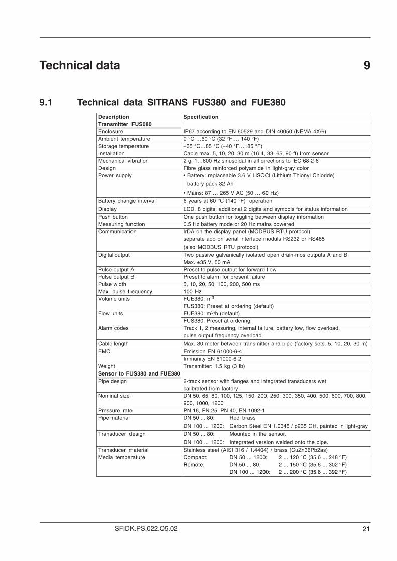
Technical data 9
9.1 Technical data SITRANS FUS380 and FUE380
22 SFIDK.PS.022.Q5.02
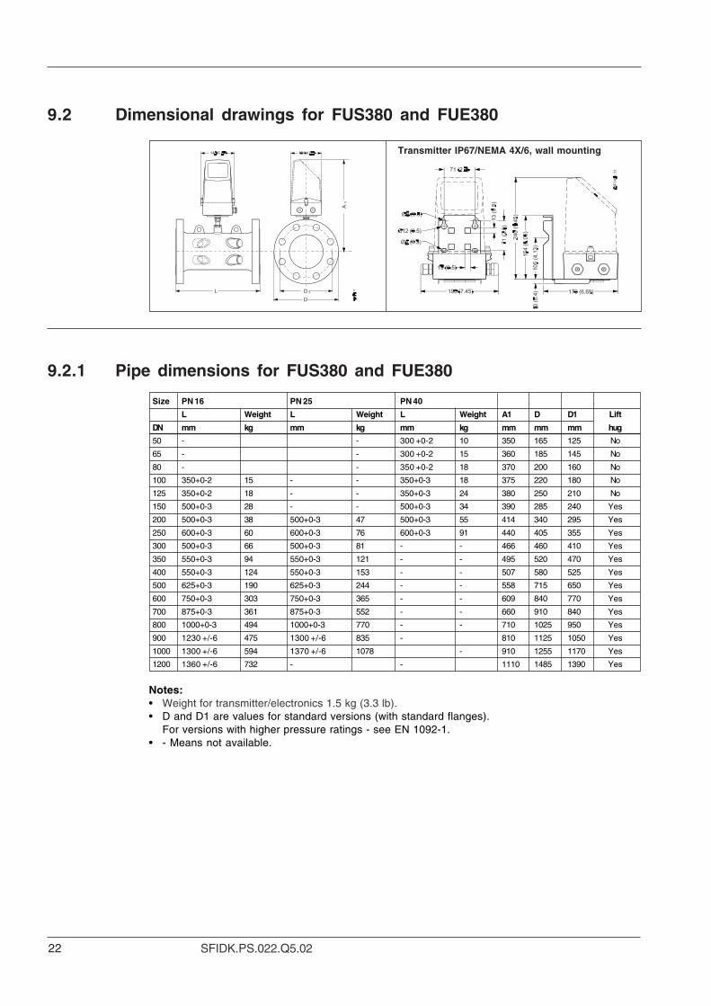
9.2.1 Pipe dimensions for FUS380 and FUE380
Transmitter IP67/NEMA 4X/6, wall mounting
9.2 Dimensional drawings for FUS380 and FUE380
Size PN 16 PN 25 PN 40
L Weight L Weight L Weight A1 D D1 Lift
DN mm kg mm kg mm kg mm mm mm hug
50 - - 300 +0-2 10 350 165 125 No
65 - - 300 +0-2 15 360 185 145 No
80 - - 350 +0-2 18 370 200 160 No
100 350+0-2 15 - - 350+0-3 18 375 220 180 No
125 350+0-2 18 - - 350+0-3 24 380 250 210 No
150 500+0-3 28 - - 500+0-3 34 390 285 240 Yes
200 500+0-3 38 500+0-3 47 500+0-3 55 414 340 295 Yes
250 600+0-3 60 600+0-3 76 600+0-3 91 440 405 355 Yes
300 500+0-3 66 500+0-3 81 - - 466 460 410 Yes
350 550+0-3 94 550+0-3 121 - - 495 520 470 Yes
400 550+0-3 124 550+0-3 153 - - 507 580 525 Yes
500 625+0-3 190 625+0-3 244 - - 558 715 650 Yes
600 750+0-3 303 750+0-3 365 - - 609 840 770 Yes
700 875+0-3 361 875+0-3 552 - - 660 910 840 Yes
800 1000+0-3 494 1000+0-3 770 - - 710 1025 950 Yes
900 1230 +/-6 475 1300 +/-6 835 - 810 1125 1050 Yes
1000 1300 +/-6 594 1370 +/-6 1078 - 910 1255 1170 Yes
1200 1360 +/-6 732 - - 1110 1485 1390 Yes
Notes:• Weight for transmitter/electronics 1.5 kg (3.3 lb).• D and D1 are values for standard versions (with standard flanges).
For versions with higher pressure ratings - see EN 1092-1.• - Means not available.
23SFIDK.PS.022.Q5.02
Size PN 16 PN 25 PN 40
L Weight L Weight L Weight A1 D D1 Lift
inch inch lb inch lb inch lb inch inch inch hug
2" - - 12 +0-0.08 22 14 6.6 5 No
2 1/2" - - 12 +0-0.08 33 14.4 7.4 5.8 No
3" - - 14 +0-0.08 40 14.8 8 6.4 No
4 13.77+0-0.08 33 - - 13.77+0-0.12 40 15 8.66 7.09 No
5 13.77+0-0.08 40 - - 13.77+0-0.12 53 15.2 9.84 8.27 No
6 19.68+0-0.12 62 - - 19.68+0-0.12 75 15.6 11.22 9.45 Yes
8 19.68+0-0.12 84 19.68+0-0.12 104 19.68+0-0.12 121 16.30 13.39 11.61 Yes
10 23.62+0-0.12 132 23.62+0-0.12 168 23.62+0-0.12 201 17.32 15.94 13.98 Yes
12 19.68+0-0.12 146 19.68+0-0.12 179 - - 18.35 18.11 16.14 Yes
14 21.65+0-0.12 207 21.65+0-0.12 267 - - 19.8 20.8 18.8 Yes
16 21.65+0-0.12 273 21.65+0-0.12 337 - - 19.96 22.83 20.67 Yes
20 24.61+0-3 419 24.61+0-3 538 - - 21.97 28.15 25.59 Yes
24 29.53+0-0.12 668 29.53+0-0.12 805 - - 23.98 33.07 30.31 Yes
28 34.45+0-0.12 796 34.45+0-0.12 1217 - - 25.98 35.83 33.07 Yes
32 39.37+0-0.12 1089 39.37+0-0.12 1698 - - 27.95 40.35 37.40 Yes
36" 49.2 +/-0.24 1047 52 +/-0.24 1841 - 32.4 45 42 Yes
40" 52 +/-0.24 1309 54.8 +/-0.34 2376 - 36.4 50.2 46.8 Yes
48" 54.4 +/-0.24 1614 - - 44.4 59.4 55.6 Yes
Notes:• Weight for transmitter/electronics 1.5 kg (3.3 lb).• D and D1 are values for standard versions (with standard flanges).
For versions with higher pressure ratings - see EN 1092-1.• - Means not available.
24 SFIDK.PS.022.Q5.02
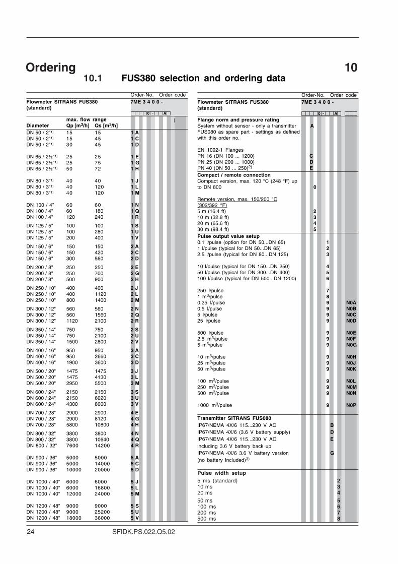
-
Ordering 1010.1 FUS380 selection and ordering data
-
Order-No. Order codeFlowmeter SITRANS FUS380 7ME 3 4 0 0 -(standard)
0 A
Flange norm and pressure ratingSystem without sensor - only a transmitter AFUS080 as spare part - settings as definedwith this order no.
EN 1092-1 FlangesPN 16 (DN 100 ... 1200) CPN 25 (DN 200 ... 1000) DPN 40 (DN 50 ... 250)2) ECompact / remote connectionCompact version, max. 120 °C (248 °F) upto DN 800 0
Remote version, max. 150/200 °C(302/392 °F)5 m (16.4 ft) 210 m (32.8 ft) 320 m (65.6 ft) 430 m (98.4 ft) 5Pulse output value setup0.1 l/pulse (option for DN 50...DN 65) 11 l/pulse (typical for DN 50...DN 65) 22.5 l/pulse (typical for DN 80...DN 125) 3
10 l/pulse (typical for DN 150...DN 250) 450 l/pulse (typical for DN 300...DN 400) 5100 l/pulse (typical for DN 500...DN 1200) 6
250 l/pulse 71 m3/pulse 80.25 l/pulse 9 N0A0.5 l/pulse 9 N0B5 l/pulse 9 N0C25 l/pulse 9 N0D
500 l/pulse 9 N0E2.5 m3/pulse 9 N0F5 m3/pulse 9 N0G
10 m3/pulse 9 N0H25 m3/pulse 9 N0J50 m3/pulse 9 N0K
100 m3/pulse 9 N0L250 m3/pulse 9 N0M500 m3/pulse 9 N0N
1000 m3/pulse 9 N0P
Transmitter SITRANS FUS080IP67/NEMA 4X/6 115...230 V AC BIP67/NEMA 4X/6 (3.6 V battery supply) DIP67/NEMA 4X/6 115...230 V AC, Eincluding 3.6 V battery back upIP67/NEMA 4X/6 3.6 V battery version G(no battery included)3)
Pulse width setup5 ms (standard) 210 ms 320 ms 450 ms 5100 ms 6200 ms 7500 ms 8
Order-No. Order codeFlowmeter SITRANS FUS380 7ME 3 4 0 0 -(standard)
0 A
max. flow rangeDiameter Qp [m3/h] Qs [m3/h]DN 50 / 2"1) 15 15 1 ADN 50 / 2"1) 15 45 1 CDN 50 / 2"1) 30 45 1 D
DN 65 / 2½"1) 25 25 1 EDN 65 / 2½"1) 25 75 1 GDN 65 / 2½"1) 50 72 1 H
DN 80 / 3"1) 40 40 1 JDN 80 / 3"1) 40 120 1 LDN 80 / 3"1) 40 120 1 M
DN 100 / 4" 60 60 1 NDN 100 / 4" 60 180 1 QDN 100 / 4" 120 240 1 R
DN 125 / 5" 100 100 1 SDN 125 / 5" 100 280 1 UDN 125 / 5" 200 400 1 V
DN 150 / 6" 150 150 2 ADN 150 / 6" 150 420 2 CDN 150 / 6" 300 560 2 D
DN 200 / 8" 250 250 2 EDN 200 / 8" 250 700 2 GDN 200 / 8" 500 900 2 H
DN 250 / 10" 400 400 2 JDN 250 / 10" 400 1120 2 LDN 250 / 10" 800 1400 2 M
DN 300 / 12" 560 560 2 NDN 300 / 12" 560 1560 2 QDN 300 / 12" 1120 2100 2 R
DN 350 / 14" 750 750 2 SDN 350 / 14" 750 2100 2 UDN 350 / 14" 1500 2800 2 V
DN 400 / 16" 950 950 3 ADN 400 / 16" 950 2660 3 CDN 400 / 16" 1900 3600 3 D
DN 500 / 20" 1475 1475 3 JDN 500 / 20" 1475 4130 3 LDN 500 / 20" 2950 5500 3 M
DN 600 / 24" 2150 2150 3 SDN 600 / 24" 2150 6020 3 UDN 600 / 24" 4300 8000 3 V
DN 700 / 28" 2900 2900 4 EDN 700 / 28" 2900 8120 4 GDN 700 / 28" 5800 10800 4 H
DN 800 / 32" 3800 3800 4 NDN 800 / 32" 3800 10640 4 QDN 800 / 32" 7600 14200 4 R
DN 900 / 36" 5000 5000 5 ADN 900 / 36" 5000 14000 5 CDN 900 / 36" 10000 20000 5 D
DN 1000 / 40" 6000 6000 5 JDN 1000 / 40" 6000 16800 5 LDN 1000 / 40" 12000 24000 5 M
DN 1200 / 48" 9000 9000 5 SDN 1200 / 48" 9000 25200 5 UDN 1200 / 48" 18000 36000 5 V
25SFIDK.PS.022.Q5.02
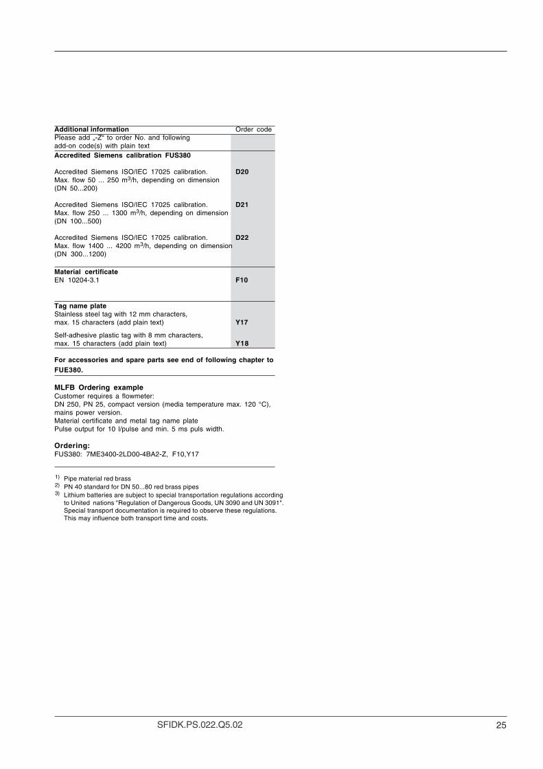
Additional information Order codePlease add „-Z“ to order No. and followingadd-on code(s) with plain textAccredited Siemens calibration FUS380
Accredited Siemens ISO/IEC 17025 calibration. D20Max. flow 50 ... 250 m3/h, depending on dimension(DN 50...200)
Accredited Siemens ISO/IEC 17025 calibration. D21Max. flow 250 ... 1300 m3/h, depending on dimension(DN 100...500)
Accredited Siemens ISO/IEC 17025 calibration. D22Max. flow 1400 ... 4200 m3/h, depending on dimension(DN 300...1200)
Material certificateEN 10204-3.1 F10
Tag name plateStainless steel tag with 12 mm characters,max. 15 characters (add plain text) Y17
Self-adhesive plastic tag with 8 mm characters,max. 15 characters (add plain text) Y18
For accessories and spare parts see end of following chapter toFUE380.
MLFB Ordering exampleCustomer requires a flowmeter:DN 250, PN 25, compact version (media temperature max. 120 °C),mains power version.Material certificate and metal tag name platePulse output for 10 l/pulse and min. 5 ms puls width.
Ordering:FUS380: 7ME3400-2LD00-4BA2-Z, F10,Y17
1) Pipe material red brass2) PN 40 standard for DN 50...80 red brass pipes3) Lithium batteries are subject to special transportation regulations according
to United nations "Regulation of Dangerous Goods, UN 3090 and UN 3091".Special transport documentation is required to observe these regulations.This may influence both transport time and costs.
26 SFIDK.PS.022.Q5.02
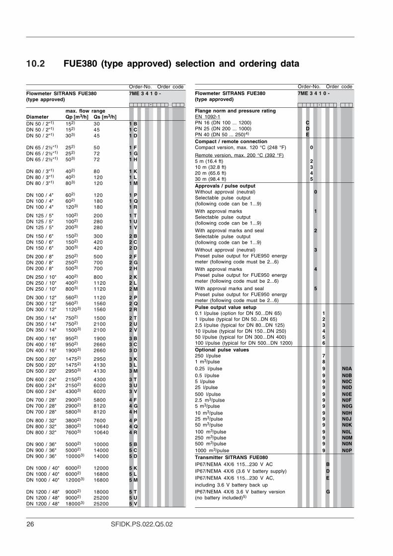
10.2 FUE380 (type approved) selection and ordering data
--
Order-No. Order codeFlowmeter SITRANS FUE380 7ME 3 4 1 0 -(type approved)
max. flow rangeDiameter Qp [m3/h] Qs [m3/h]DN 50 / 2"1) 152) 30 1 BDN 50 / 2"1) 152) 45 1 CDN 50 / 2"1) 303) 45 1 D
DN 65 / 2½"1) 252) 50 1 FDN 65 / 2½"1) 252) 72 1 GDN 65 / 2½"1) 503) 72 1 H
DN 80 / 3"1) 402) 80 1 KDN 80 / 3"1) 402) 120 1 LDN 80 / 3"1) 803) 120 1 M
DN 100 / 4" 602) 120 1 PDN 100 / 4" 602) 180 1 QDN 100 / 4" 1203) 180 1 R
DN 125 / 5" 1002) 200 1 TDN 125 / 5" 1002) 280 1 UDN 125 / 5" 2003) 280 1 V
DN 150 / 6" 1502) 300 2 BDN 150 / 6" 1502) 420 2 CDN 150 / 6" 3003) 420 2 D
DN 200 / 8" 2502) 500 2 FDN 200 / 8" 2502) 700 2 GDN 200 / 8" 5003) 700 2 H
DN 250 / 10" 4002) 800 2 KDN 250 / 10" 4002) 1120 2 LDN 250 / 10" 8003) 1120 2 M
DN 300 / 12" 5602) 1120 2 PDN 300 / 12" 5602) 1560 2 QDN 300 / 12" 11203) 1560 2 R
DN 350 / 14" 7502) 1500 2 TDN 350 / 14" 7502) 2100 2 UDN 350 / 14" 15003) 2100 2 V
DN 400 / 16" 9502) 1900 3 BDN 400 / 16" 9502) 2660 3 CDN 400 / 16" 19003) 2660 3 D
DN 500 / 20" 14752) 2950 3 KDN 500 / 20" 14752) 4130 3 LDN 500 / 20" 29503) 4130 3 M
DN 600 / 24" 21502) 4300 3 TDN 600 / 24" 21502) 6020 3 UDN 600 / 24" 43003) 6020 3 V
DN 700 / 28" 29002) 5800 4 FDN 700 / 28" 29002) 8120 4 GDN 700 / 28" 58003) 8120 4 H
DN 800 / 32" 38002) 7600 4 PDN 800 / 32" 38002) 10640 4 QDN 800 / 32" 76003) 10640 4 R
DN 900 / 36" 50002) 10000 5 BDN 900 / 36" 50002) 14000 5 CDN 900 / 36" 100003) 14000 5 D
DN 1000 / 40" 60002) 12000 5 KDN 1000 / 40" 60002) 16800 5 LDN 1000 / 40" 120003) 16800 5 M
DN 1200 / 48" 90002) 18000 5 TDN 1200 / 48" 90002) 25200 5 UDN 1200 / 48" 180003) 25200 5 V
Order-No. Order codeFlowmeter SITRANS FUE380 7ME 3 4 1 0 -(type approved)
Flange norm and pressure ratingEN 1092-1PN 16 (DN 100 ... 1200) CPN 25 (DN 200 ... 1000) DPN 40 (DN 50 ... 250)4) ECompact / remote connectionCompact version, max. 120 °C (248 °F) 0
Remote version, max. 200 °C (392 °F)5 m (16.4 ft) 210 m (32.8 ft) 320 m (65.6 ft) 430 m (98.4 ft) 5Approvals / pulse outputWithout approval (neutral) 0Selectable pulse output(following code can be 1...9)
With approval marks 1Selectable pulse output(following code can be 1...9)
With approval marks and seal 2Selectable pulse output(following code can be 1...9)
Without approval (neutral) 3Preset pulse output for FUE950 energymeter (following code must be 2...6)
With approval marks 4Preset pulse output for FUE950 energymeter (following code must be 2...6)
With approval marks and seal 5Preset pulse output for FUE950 energymeter (following code must be 2...6)Pulse output value setup0.1 l/pulse (option for DN 50...DN 65) 11 l/pulse (typical for DN 50...DN 65) 22.5 l/pulse (typical for DN 80...DN 125) 310 l/pulse (typical for DN 150...DN 250) 450 l/pulse (typical for DN 300...DN 400) 5100 l/pulse (typical for DN 500...DN 1200) 6Optional pulse values250 l/pulse 71 m3/pulse 80.25 l/pulse 9 N0A0.5 l/pulse 9 N0B5 l/pulse 9 N0C25 l/pulse 9 N0D500 l/pulse 9 N0E2.5 m3/pulse 9 N0F5 m3/pulse 9 N0G10 m3/pulse 9 N0H25 m3/pulse 9 N0J50 m3/pulse 9 N0K100 m3/pulse 9 N0L250 m3/pulse 9 N0M500 m3/pulse 9 N0N1000 m3/pulse 9 N0PTransmitter SITRANS FUE080IP67/NEMA 4X/6 115...230 V AC BIP67/NEMA 4X/6 (3.6 V battery supply) DIP67/NEMA 4X/6 115...230 V AC, Eincluding 3.6 V battery back upIP67/NEMA 4X/6 3.6 V battery version G(no battery included)5)
27SFIDK.PS.022.Q5.02
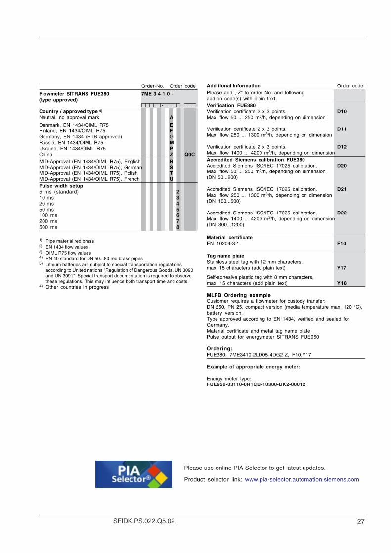
-
Additional information Order codePlease add „-Z“ to order No. and followingadd-on code(s) with plain textVerification FUE380Verification certificate 2 x 3 points. D10Max. flow 50 ... 250 m3/h, depending on dimension
Verification certificate 2 x 3 points. D11Max. flow 250 ... 1300 m3/h, depending on dimension
Verification certificate 2 x 3 points. D12Max. flow 1400 ... 4200 m3/h, depending on dimensionAccredited Siemens calibration FUE380Accredited Siemens ISO/IEC 17025 calibration. D20Max. flow 50 ... 250 m3/h, depending on dimension(DN 50...200)
Accredited Siemens ISO/IEC 17025 calibration. D21Max. flow 250 ... 1300 m3/h, depending on dimension(DN 100...500)
Accredited Siemens ISO/IEC 17025 calibration. D22Max. flow 1400 ... 4200 m3/h, depending on dimension(DN 300...1200)
Material certificateEN 10204-3.1 F10
Tag name plateStainless steel tag with 12 mm characters,max. 15 characters (add plain text) Y17
Self-adhesive plastic tag with 8 mm characters,max. 15 characters (add plain text) Y18
MLFB Ordering exampleCustomer requires a flowmeter for custody transfer:DN 250, PN 25, compact version (media temperature max. 120 °C),battery version.Type approved according to EN 1434, verified and sealed forGermany.Material certificate and metal tag name platePulse output for energymeter SITRANS FUE950
Ordering:FUE380: 7ME3410-2LD05-4DG2-Z, F10,Y17
Example of appropriate energy meter:
Energy meter type:FUE950-03110-0R1CB-10300-DK2-00012
Order-No. Order code
Flowmeter SITRANS FUE380 7ME 3 4 1 0 -(type approved)
-
Country / approved type 6)
Neutral, no approval mark A
Denmark, EN 1434/OIML R75 EFinland, EN 1434/OIML R75 FGermany, EN 1434 (PTB approved) GRussia, EN 1434/OIML R75 MUkraine, EN 1434/OIML R75 PChina Z Q0CMID-Approval (EN 1434/OIML R75), English RMID-Approval (EN 1434/OIML R75), German SMID-Approval (EN 1434/OIML R75), Polish TMID-Approval (EN 1434/OIML R75), French UPulse width setup5 ms (standard) 210 ms 320 ms 450 ms 5100 ms 6200 ms 7500 ms 8
1) Pipe material red brass2) EN 1434 flow values3) OIML R75 flow values4) PN 40 standard for DN 50...80 red brass pipes5) Lithium batteries are subject to special transportation regulations
according to United nations "Regulation of Dangerous Goods, UN 3090and UN 3091". Special transport documentation is required to observethese regulations. This may influence both transport time and costs.
4) Other countries in progress
Please use online PIA Selector to get latest updates.
Product selector link: www.pia-selector.automation.siemens.com
28 SFIDK.PS.022.Q5.02
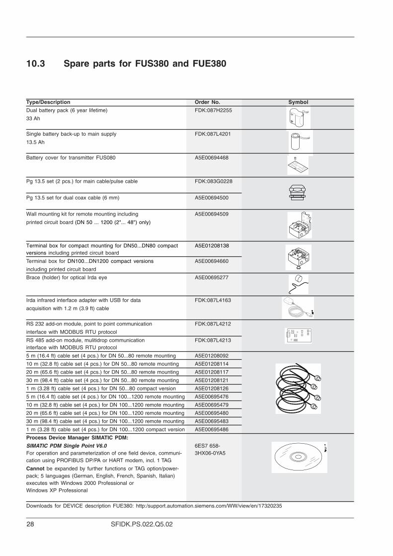
10.3 Spare parts for FUS380 and FUE380
Type/Description Order No. Symbol
Dual battery pack (6 year lifetime) FDK:087H2255
33 Ah
Single battery back-up to main supply FDK:087L4201
13.5 Ah
Battery cover for transmitter FUS080 A5E00694468
Pg 13.5 set (2 pcs.) for main cable/pulse cable FDK:083G0228
Pg 13.5 set for dual coax cable (6 mm) A5E00694500
Wall mounting kit for remote mounting including A5E00694509
printed circuit board (DN 50 ... 1200 (2"... 48") only)
Terminal box for compact mounting for DN50...DN80 compact A5E01208138versions including printed circuit board
Terminal box for DN100...DN1200 compact versions A5E00694660
including printed circuit board
Brace (holder) for optical Irda eye A5E00695277
Irda infrared interface adapter with USB for data FDK:087L4163
acquisition with 1.2 m (3.9 ft) cable
RS 232 add-on module, point to point communication FDK:087L4212
interface with MODBUS RTU protocol
RS 485 add-on module, mulitidrop communication FDK:087L4213interface with MODBUS RTU protocol
5 m (16.4 ft) cable set (4 pcs.) for DN 50...80 remote mounting A5E01208092
10 m (32.8 ft) cable set (4 pcs.) for DN 50...80 remote mounting A5E01208114
20 m (65.6 ft) cable set (4 pcs.) for DN 50...80 remote mounting A5E01208117
30 m (98.4 ft) cable set (4 pcs.) for DN 50...80 remote mounting A5E01208121
1 m (3.28 ft) cable set (4 pcs.) for DN 50...80 compact version A5E01208126
5 m (16.4 ft) cable set (4 pcs.) for DN 100...1200 remote mounting A5E00695476
10 m (32.8 ft) cable set (4 pcs.) for DN 100...1200 remote mounting A5E00695479
20 m (65.6 ft) cable set (4 pcs.) for DN 100...1200 remote mounting A5E00695480
30 m (98.4 ft) cable set (4 pcs.) for DN 100...1200 remote mounting A5E00695483
1 m (3.28 ft) cable set (4 pcs.) for DN 100...1200 compact version A5E00695486
Process Device Manager SIMATIC PDM:
SIMATIC PDM Single Point V6.0 6ES7 658-For operation and parameterization of one field device, communi- 3HX06-0YA5cation using PROFIBUS DP/PA or HART modem, incl. 1 TAG
Cannot be expanded by further functions or TAG option/power-pack; 5 languages (German, English, French, Spanish, Italian)executes with Windows 2000 Professional orWindows XP Professional
Downloads for DEVICE description FUE380: http:/support.automation.siemens.com/WW/view/en/17320235
29SFIDK.PS.022.Q5.02
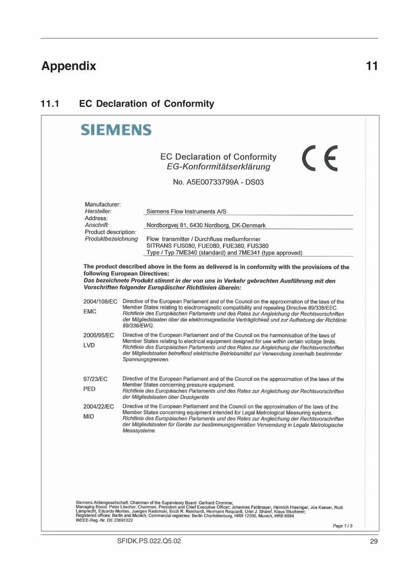
Appendix 11
11.1 EC Declaration of Conformity
30 SFIDK.PS.022.Q5.02
31SFIDK.PS.022.Q5.02

Siemens has checked the contents of this manual for agreement with thehardware and software described. Since deviations cannot be precluded entirely,Siemens cannot guarantee full agreement. However, the data in this manual arereviewed regularly and any necessary corrections included in subsequent editions.Suggestions for improvement are always welcome.
Technical data subject to change without prior notice.
The reproduction, transmission or use of this document or its contents is not permittedwithout express written authority.Offenders will be liable for damages. All rights, including rights created by patent grant orregistration of a utility model or design, are reserved.
Copyright © Siemens AG 09.2007 All Rights Reserved
Siemens Flow Instruments A/SNordborgvej 81DK-6430 Nordborg
Order no.: A5E00730100-05Printed in: Denmark

![SITRANS F C MASSFLO€¦ · SITRANS F C MASSFLO SFIDK.PS.028.M1.02 7 3. Technical data Measurement of Mass flow [kg/s], volume flow [l/s], fraction [%], Brix, density [kg/m3], temperature](https://img.pdfslide.us/doc/110x75/5f56a2f2d04d9e227523a1e6/sitrans-f-c-massflo-sitrans-f-c-massflo-sfidkps028m102-7-3-technical-data-measurement.jpg)