Embed Size (px)
Citation preview
SITRANS F flowmetersSITRANS F US
System information and selection guide
4/259Siemens FI 01 · 2010
4
System information and selection guide
SITRANS F US Clamp-on meters FUS1010 (Standard)
FUS1020 (Basic)
FUP1010 (Portable)
FUE1010 (Energy)
FUH1010 (Oil)
FUG1010 (Gas)
Industry/Applications
Water and aqueous solutions X X X
Utility district heating, cooling X X X X
Chemical X X X
Hydrocarbons/Petrochemical, multiple products or varying viscosity, liquefied gases, net and gross volume
X X
Hydrocarbons (Single product with limited viscosity range) gross volume
X X X
Very low flow (<10 lpm) in small pipes X X X
Natural gas X
Process gas X
Slurries or liquids with high percentage of undissolved gases
X X
High temperature liquids > 120 °C (248 °F) X1) X1) X1) X1) X1)
Aerospace or hydraulic test X2) X2)
Refrigeration liquids X X X X
Food products X X X
Design
Field clamp-on (non-intrusive) X X X X X X
Doppler (Reflexor) hybrid capability X4) X X
Standard volume or mass flow; per API 2540 X
Interface detection X
Density output X
Standard volume or mass flow; per AGA 8 X
Differential temperature with energy calculation X
Temperature measurement X X X X X
Analog input X X X X X
Large graphics display (optional) X X X X X
Diagnostic PC software (DataView) X X X X X X
Number of acoustic paths and channels
1-channel X X X X X X
2-path X X X X X X
2-channel w/ arithmetic function X X X X
4-path / (special order) X X X
4-channel w/ sum of active channels X
Transmitter enclosure
IP65 (NEMA 4) X
IP65 (NEMA 4X) X X X X
IP67 X
IP40 (NEMA 1) X3)
IP65 (NEMA 7) Compact X X X
IP66 (NEMA 7) Wall mount X X X1) Special order high temperature clamp-on transducer2) Special order Aerospace clip-on transducer recommended3) Available with portable energy systems4) Not for NEMA 7 Compact
© Siemens AG 2009
SITRANS F flowmetersSITRANS F US
System information and selection guide
4/260 Siemens FI 01 · 2010
4
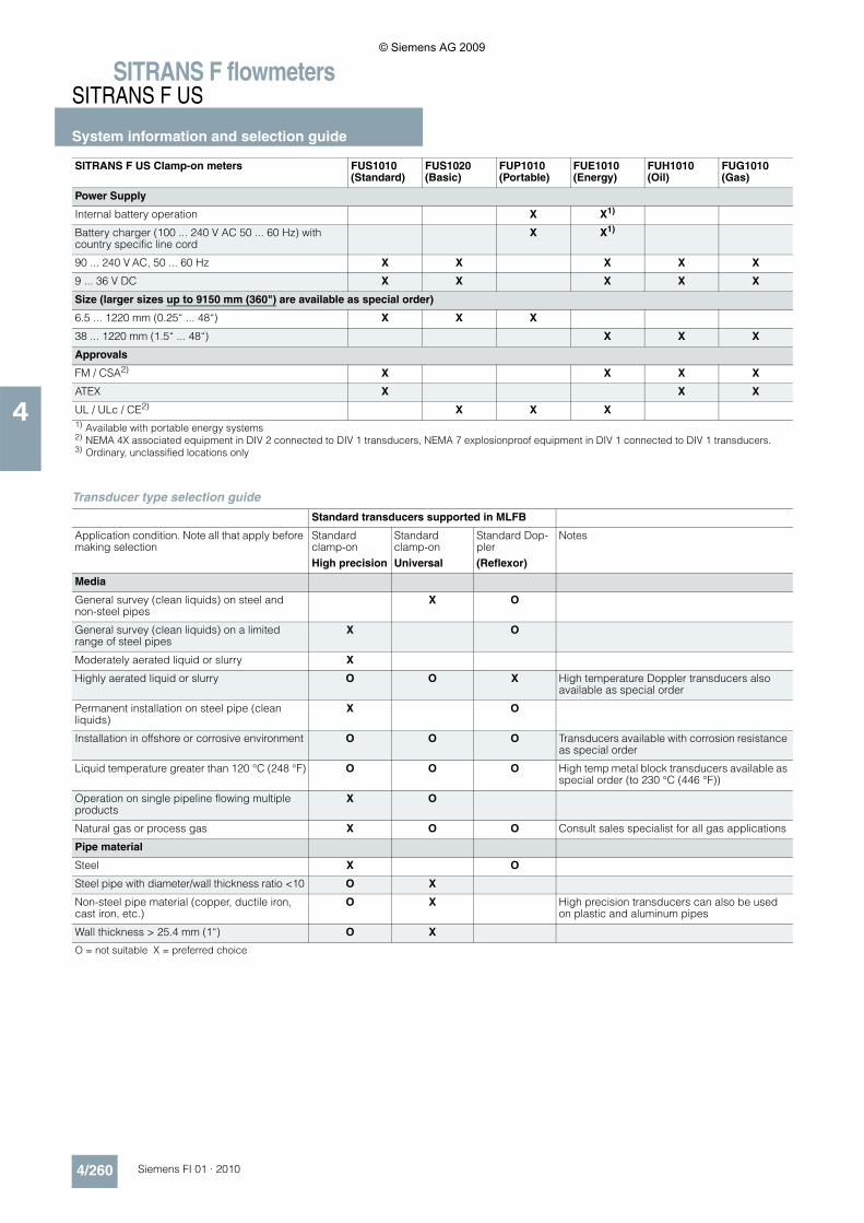
Transducer type selection guide
Power Supply
Internal battery operation X X1)
Battery charger (100 ... 240 V AC 50 ... 60 Hz) with country specific line cord
X X1)
90 ... 240 V AC, 50 ... 60 Hz X X X X X
9 ... 36 V DC X X X X X
Size (larger sizes up to 9150 mm (360") are available as special order)
6.5 ... 1220 mm (0.25“ ... 48“) X X X
38 ... 1220 mm (1.5“ ... 48“) X X X
Approvals
FM / CSA2) X X X X
ATEX X X X
UL / ULc / CE2) X X X1) Available with portable energy systems2) NEMA 4X associated equipment in DIV 2 connected to DIV 1 transducers, NEMA 7 explosionproof equipment in DIV 1 connected to DIV 1 transducers.3) Ordinary, unclassified locations only
SITRANS F US Clamp-on meters FUS1010 (Standard)
FUS1020 (Basic)
FUP1010 (Portable)
FUE1010 (Energy)
FUH1010 (Oil)
FUG1010 (Gas)
Standard transducers supported in MLFB
Application condition. Note all that apply before making selection
Standard clamp-onHigh precision
Standard clamp-onUniversal
Standard Dop-pler(Reflexor)
Notes
Media
General survey (clean liquids) on steel and non-steel pipes
X O
General survey (clean liquids) on a limited range of steel pipes
X O
Moderately aerated liquid or slurry X
Highly aerated liquid or slurry O O X High temperature Doppler transducers also available as special order
Permanent installation on steel pipe (clean liquids)
X O
Installation in offshore or corrosive environment O O O Transducers available with corrosion resistance as special order
Liquid temperature greater than 120 °C (248 °F) O O O High temp metal block transducers available as special order (to 230 °C (446 °F))
Operation on single pipeline flowing multiple products
X O
Natural gas or process gas X O O Consult sales specialist for all gas applications
Pipe material
Steel X O
Steel pipe with diameter/wall thickness ratio <10 O X
Non-steel pipe material (copper, ductile iron, cast iron, etc.)
O X High precision transducers can also be used on plastic and aluminum pipes
Wall thickness > 25.4 mm (1“) O X
O = not suitable X = preferred choice
© Siemens AG 2009
SITRANS F flowmetersSITRANS F US
System information and selection guide
4/261Siemens FI 01 · 2010
4
■ Function
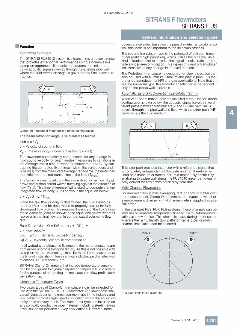
Operating Principle
The SITRANS FUS1010 system is a transit-time ultrasonic meter that provides exceptional performance using a non-invasive clamp-on approach. Ultrasonic transducers transmit and re-ceive acoustic signals directly though the existing pipe wall, where the fluid refraction angle is governed by Snell’s law of re-fraction.
Clamp-on transducer mounted in a reflect configuration
The beam refraction angle is calculated as follows:
sinθ = c / Vφc = Velocity of sound in fluidVϕ = Phase velocity (a constant in the pipe wall)
The flowmeter automatically compensates for any change in fluid sound velocity (or beam angle) in response to variations in the average transit-time between transducers A and B. By sub-tracting the computed fixed times (within the transducers and pipe wall) from the measured average transit-time, the meter can then infer the required transit-time in the fluid (TFluid).
The Sound waves traveling in the same direction as flow (TA,B) arrive earlier than sound waves traveling against the direction of flow (TB,A). This time difference (Δt) is used to compute the line integrated flow velocity (v) as shown in the equation below:
v = Vϕ / 2 ⋅ Δt / TFluid
Once the raw flow velocity is determined, the fluid Reynolds number (Re) must be determined to properly correct for fully developed flow profile. This requires the entry of the fluid’s kine-matic viscosity (visc) as shown in the equations below, where Q represents the final flow profile compensated volumetric flow rate.
Re = Di ⋅ v / visc ⋅ Q = K(Re) ⋅ ( π / 4 ⋅ Di2 ) ⋅ vv = Flow velocityvisc = μ / ρ = (dynamic viscosity / density)K(Re) = Reynolds flow profile compensation
In all wetted type ultrasonic flowmeters the meter constants are configured prior to leaving the factory. As this is not possible with clamp-on meters, the settings must be made by the customer at the time of installation. These settings include pipe diameter, wall thickness, liquid viscosity, etc.
SITRANS Clamp-On meters that include temperature sensing can be configured to dynamically infer changes in fluid viscosity for the purpose of computing the most accurate flow profile com-pensation (KRe).
Ultrasonic Transducer Types
Two basic types of Clamp-On transducers can be selected for use with the SITRANS FUS1010 flowmeter. The lower cost “uni-versal” transducer is the most common type in the industry and is suitable for most single liquid application where the sound ve-locity does not vary much. This transducer type can be used on any sonically conductive pipe material (including steel) making it well suited for portable survey applications. Universal trans-
ducers are selected based on the pipe diameter range alone, so wall thickness is not important to the selection process.
The second transducer type is the patented WideBeam trans-ducer (called high precision), which utilizes the pipe wall as a kind of loudspeaker to optimize the signal to noise ratio and pro-vide a wider area of vibration. This makes this kind of transducer less sensitive to any change in the fluid medium.
The WideBeam transducer is designed for steel pipes, but can also be used with aluminum, titanium and plastic pipe. It is the preferred transducer for HPI and gas applications. Note that un-like the universal type, this transducer selection is dependent only on the pipe’s wall thickness.
Automatic Zero Drift Correction (ZeroMatic Path™)
When WideBeam transducers are installed in the “Reflect” mode configuration shown below, the acoustic signal travels in two dif-ferent paths between transducers A and B. One path “ACB” travels through the pipe wall and fluid, while the other path “AB” never enters the fluid medium.
This later path provides the meter with a reference signal thatis completely independent of flow rate and can therefore be used as a measure of transducer “mis-match”. By continually analyzing this pipe wall signal the FUS1010 meter can dynami-cally correct for flow errors caused by zero drift.
Multi-Channel Flowmeters
For improved flow profile averaging, redundancy, or better cost per measurement, Clamp-On meters can be supplied with 1 or 2 measurement channel, with 4 channel meters supplied as spe-cial order.
In the standard FUS, FUP, FUE systems, these channels can be installed on separate independent lines or in a multi-beam instal-lation as shown below. This choice is made during meter setup, where either a multi-path (two paths on same pipe) or multi-channel installation can be selected.
Dual path installation example
c
Di
A B
vθ
C
A B
Path 1 Path 2
© Siemens AG 2009
SITRANS F flowmetersSITRANS F US
System information and selection guide
4/262 Siemens FI 01 · 2010
4
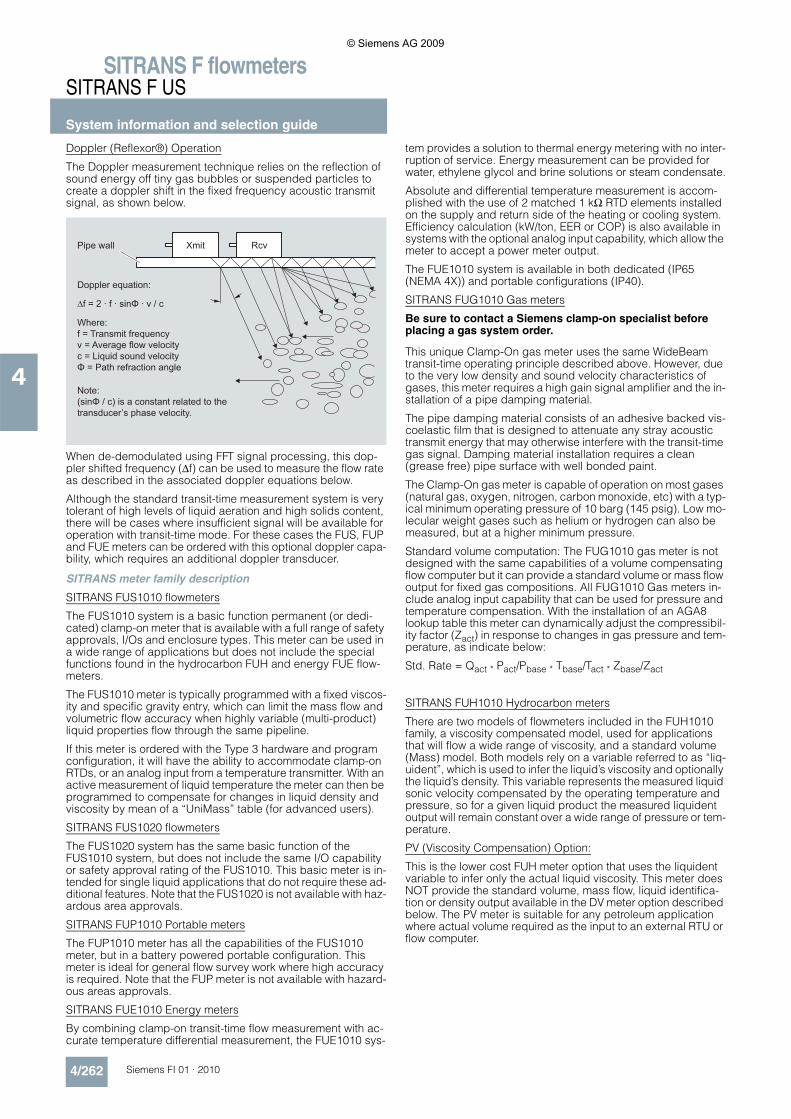
Doppler (Reflexor®) Operation
The Doppler measurement technique relies on the reflection of sound energy off tiny gas bubbles or suspended particles to create a doppler shift in the fixed frequency acoustic transmit signal, as shown below.
When de-demodulated using FFT signal processing, this dop-pler shifted frequency (Δf) can be used to measure the flow rate as described in the associated doppler equations below.
Although the standard transit-time measurement system is very tolerant of high levels of liquid aeration and high solids content, there will be cases where insufficient signal will be available for operation with transit-time mode. For these cases the FUS, FUP and FUE meters can be ordered with this optional doppler capa-bility, which requires an additional doppler transducer.
SITRANS meter family description
SITRANS FUS1010 flowmeters
The FUS1010 system is a basic function permanent (or dedi-cated) clamp-on meter that is available with a full range of safety approvals, I/Os and enclosure types. This meter can be used in a wide range of applications but does not include the special functions found in the hydrocarbon FUH and energy FUE flow-meters.
The FUS1010 meter is typically programmed with a fixed viscos-ity and specific gravity entry, which can limit the mass flow and volumetric flow accuracy when highly variable (multi-product) liquid properties flow through the same pipeline.
If this meter is ordered with the Type 3 hardware and program configuration, it will have the ability to accommodate clamp-on RTDs, or an analog input from a temperature transmitter. With an active measurement of liquid temperature the meter can then be programmed to compensate for changes in liquid density and viscosity by mean of a “UniMass” table (for advanced users).
SITRANS FUS1020 flowmeters
The FUS1020 system has the same basic function of the FUS1010 system, but does not include the same I/O capability or safety approval rating of the FUS1010. This basic meter is in-tended for single liquid applications that do not require these ad-ditional features. Note that the FUS1020 is not available with haz-ardous area approvals.
SITRANS FUP1010 Portable meters
The FUP1010 meter has all the capabilities of the FUS1010 meter, but in a battery powered portable configuration. This meter is ideal for general flow survey work where high accuracy is required. Note that the FUP meter is not available with hazard-ous areas approvals.
SITRANS FUE1010 Energy meters
By combining clamp-on transit-time flow measurement with ac-curate temperature differential measurement, the FUE1010 sys-
tem provides a solution to thermal energy metering with no inter-ruption of service. Energy measurement can be provided for water, ethylene glycol and brine solutions or steam condensate.
Absolute and differential temperature measurement is accom-plished with the use of 2 matched 1 kΩ RTD elements installed on the supply and return side of the heating or cooling system. Efficiency calculation (kW/ton, EER or COP) is also available in systems with the optional analog input capability, which allow the meter to accept a power meter output.
The FUE1010 system is available in both dedicated (IP65 (NEMA 4X)) and portable configurations (IP40).
SITRANS FUG1010 Gas meters
Be sure to contact a Siemens clamp-on specialist before placing a gas system order.
This unique Clamp-On gas meter uses the same WideBeam transit-time operating principle described above. However, due to the very low density and sound velocity characteristics of gases, this meter requires a high gain signal amplifier and the in-stallation of a pipe damping material.
The pipe damping material consists of an adhesive backed vis-coelastic film that is designed to attenuate any stray acoustic transmit energy that may otherwise interfere with the transit-time gas signal. Damping material installation requires a clean (grease free) pipe surface with well bonded paint.
The Clamp-On gas meter is capable of operation on most gases (natural gas, oxygen, nitrogen, carbon monoxide, etc) with a typ-ical minimum operating pressure of 10 barg (145 psig). Low mo-lecular weight gases such as helium or hydrogen can also be measured, but at a higher minimum pressure.
Standard volume computation: The FUG1010 gas meter is not designed with the same capabilities of a volume compensating flow computer but it can provide a standard volume or mass flow output for fixed gas compositions. All FUG1010 Gas meters in-clude analog input capability that can be used for pressure and temperature compensation. With the installation of an AGA8 lookup table this meter can dynamically adjust the compressibil-ity factor (Zact) in response to changes in gas pressure and tem-perature, as indicate below:
Std. Rate = Qact * Pact/Pbase * Tbase/Tact * Zbase/Zact
SITRANS FUH1010 Hydrocarbon meters
There are two models of flowmeters included in the FUH1010 family, a viscosity compensated model, used for applications that will flow a wide range of viscosity, and a standard volume (Mass) model. Both models rely on a variable referred to as “liq-uident”, which is used to infer the liquid’s viscosity and optionally the liquid’s density. This variable represents the measured liquid sonic velocity compensated by the operating temperature and pressure, so for a given liquid product the measured liquident output will remain constant over a wide range of pressure or tem-perature.
PV (Viscosity Compensation) Option:
This is the lower cost FUH meter option that uses the liquident variable to infer only the actual liquid viscosity. This meter does NOT provide the standard volume, mass flow, liquid identifica-tion or density output available in the DV meter option described below. The PV meter is suitable for any petroleum application where actual volume required as the input to an external RTU or flow computer.
Doppler equation:
XmitPipe wall Rcv
Where:f = Transmit frequencyv = Average flow velocityc = Liquid sound velocityΦ = Path refraction angle
Note:(sinΦ / c) is a constant related to the transducer’s phase velocity.
∆f = 2 · f · sinΦ · v / c
© Siemens AG 2009
SITRANS F flowmetersSITRANS F US
System information and selection guide
4/263Siemens FI 01 · 2010
4
DV (Standard Volume) Option:
This Liquident variable can also be used to identify the liquid’s name (gasoline, fuel oil, crude oil, etc) as well as it’s physical properties (specify gravity, API, viscosity and compressibility) at base conditions. With this information the meter can be config-ured to output a temperature and pressure compensated (Stan-dard) volume flow rate using the API 2540 and API MPMS chap-ter 11.2.1 methods as shown below.
Available outputs from this meter include: API, Density, Mass Flowrate, Standard Volume Flowrate and Liquid Identification.
B (Interface Detection) Option:
This meter option is designed to provide all the Non-Flow capa-bilities of a DV meter, making it an ideal non-intrusive alternative to a densitometer, interface detector or pig detector. Be aware that this meter does NOT measure flow rate.
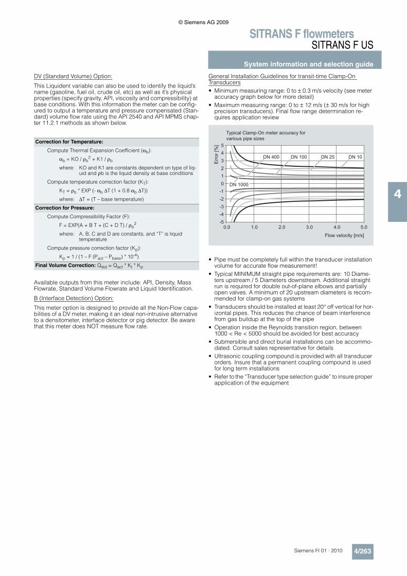
General Installation Guidelines for transit-time Clamp-On Transducers• Minimum measuring range: 0 to ± 0.3 m/s velocity (see meter
accuracy graph below for more detail)• Maximum measuring range: 0 to ± 12 m/s (± 30 m/s for high
precision transducers). Final flow range determination re-quires application review
• Pipe must be completely full within the transducer installation volume for accurate flow measurement!
• Typical MINIMUM straight pipe requirements are: 10 Diame-ters upstream / 5 Diameters downstream. Additional straight run is required for double out-of-plane elbows and partially open valves. A minimum of 20 upstream diameters is recom-mended for clamp-on gas systems
• Transducers should be installed at least 20° off vertical for hor-izontal pipes. This reduces the chance of beam interference from gas buildup at the top of the pipe
• Operation inside the Reynolds transition region, between 1000 < Re < 5000 should be avoided for best accuracy
• Submersible and direct burial installations can be accommo-dated. Consult sales representative for details
• Ultrasonic coupling compound is provided with all transducer orders. Insure that a permanent coupling compound is used for long term installations
• Refer to the “Transducer type selection guide” to insure proper application of the equipment
Correction for Temperature:
Compute Thermal Expansion Coefficient (αb):
αb = KO / ρb2 + K1 / ρb
where: KO and K1 are constants dependent on type of liq-uid and ρb is the liquid density at base conditions
Compute temperature correction factor (KT):
KT = ρb * EXP (- αb ΔT (1 + 0.8 αb ΔT))
where: ΔT = (T – base temperature)
Correction for Pressure:
Compute Compressibility Factor (F):
F = EXP(A + B T + (C + D T) / ρb2
where: A, B, C and D are constants, and “T” is liquidtemperature
Compute pressure correction factor (Kp):
Kp = 1 / (1 – F (Pact – Pbase) * 10-4)
Final Volume Correction: Qstd = Qact * Kt * Kp
Err
or [%
]
Flow velocity [m/s]
Typical Clamp-On meter accuracy for various pipe sizes
543210
-1-2-3-4-5
0.0 1.0 2.0 3.0 4.0 5.0
DN 10DN 25DN 100
DN 1000
DN 400
© Siemens AG 2009
SITRANS F flowmetersSITRANS F US
System information and selection guide
4/264 Siemens FI 01 · 2010
4
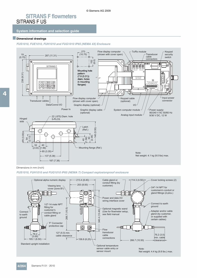
■ Dimensional drawings
FUS1010, FUE1010, FUH1010 and FUG1010 IP65 (NEMA 4X) Enclosure
DImensions in mm (inch)
FUS1010, FUH1010 and FUG1010 IP65 (NEMA 7) Compact explosionproof enclosure
Power In
Note:Net weight: 4.1 kg (9.0 lbs) max.
Flow display computer(shown with cover open)
Flow display computer(shown with cover open)
Graphic display cable(optional)
Graphic display (optional)
22 (.875) Diam. hole5-PLCS.
Mounting flange (Ref.)
Latch (Ref.)
Analog input module
I/O
Keypad cable(optional)
System computer module
Transducer cableconnectors
Tx/Rx module Keypad securityswitch
Input powerconnector
Power supply:90/240 V AC 50/60 Hz9/36 V DC, 12 W
Hinged side
Transducer cables
Data/Conrol I/O
Mounting hole pattern(7.8 (0.31)) diam. holesin mounting flanges)
Mounting hole pattern(7.8 (0.31)) diam. holesin mounting flanges)
Dual channelinput module
Remove cover for access to I/O wiring terminal
Channel 1 Channel 2
SITRANS F
187 (7.38)
137 (5.38)
85 (3.35)
40(1.56)
287 (11.31)
76 (3
.00)
54
(2.1
3)
52 (2.03)
19 (0.75)
236
(9.3
1)
60
(2.3
8)
40(1
.56) 14
0 (5
.50)
273(10.75)
152
(6.0
)
Note:Net weight: 4.4 kg (9.8 lbs.) max.
Standard upright installation
Power and data I/O wiring interface cover
Optional magnetic wand (Use for flowmeter setup, see field manual
Cover locking screws (2)
3/4"-14 NPT for customers’s conduit or gland fittings (2-plcs.)
Optional alpha numeric display
Viewing lenscover (zone B1)
Flow transducer cable connections
'F' Connector protective cap
76.2 (3.0) min. cable clearance
127 (5.0) min. cable clearance
Optional temperature sensor cable entry or sensor mount
Connect to earth ground
Connect to earth ground
Cable gland or conduit fitting (by customer)
Adapter and/or cable gland (by customer, or supplied with certain cables)
1/2"-14 male NPT fitting for customer’s conduit fitting or cable gland
o
203 (8.00)
213.4 (8.40)
266.
7 (1
0.5)
76.2(3.00)
114.3 (4.50)
165.1 (6.50) 158.8 (6.25) 266.7 (10.50)
340.
4 (1
3.40
)
© Siemens AG 2009
SITRANS F flowmetersSITRANS F US
System information and selection guide
4/265Siemens FI 01 · 2010
4
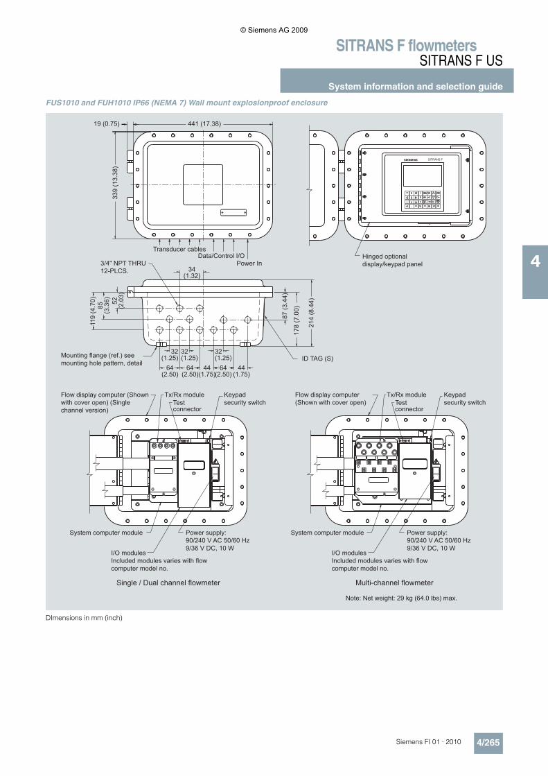
FUS1010 and FUH1010 IP66 (NEMA 7) Wall mount explosionproof enclosure
DImensions in mm (inch)
Power supply:90/240 V AC 50/60 Hz9/36 V DC, 10 W
Flow display computer (Shown with cover open)
Flow display computer (Shown with cover open) (Single channel version)
System computer module
Multi-channel flowmeterSingle / Dual channel flowmeter
Tx/Rx module
System computer module
I/O modulesIncluded modules varies with flow computer model no.
I/O modulesIncluded modules varies with flow computer model no.
Keypad security switchTest
connector
Note: Net weight: 29 kg (64.0 lbs) max.
Power supply:90/240 V AC 50/60 Hz9/36 V DC, 10 W
Hinged optional display/keypad panel
Transducer cables
Power InData/Control I/O
Mounting flange (ref.) see mounting hole pattern, detail
3/4" NPT THRU 12-PLCS.
ID TAG (S)
Tx/Rx module Keypad security switchTest
connector
s
119
(4.7
0)85
(3
.36) 52
(2.0
3)
44(1.75)
64(2.50)
32(1.25)
32(1.25)
64(2.50)
64(2.50)
32(1.25)
87 (3
.44)
214
(8.4
4)
441 (17.38)19 (0.75)33
9 (1
3.38
)
178
(7.0
0)
34 (1.32)
44(1.75)
© Siemens AG 2009
SITRANS F flowmetersSITRANS F US
System information and selection guide
4/266 Siemens FI 01 · 2010
4
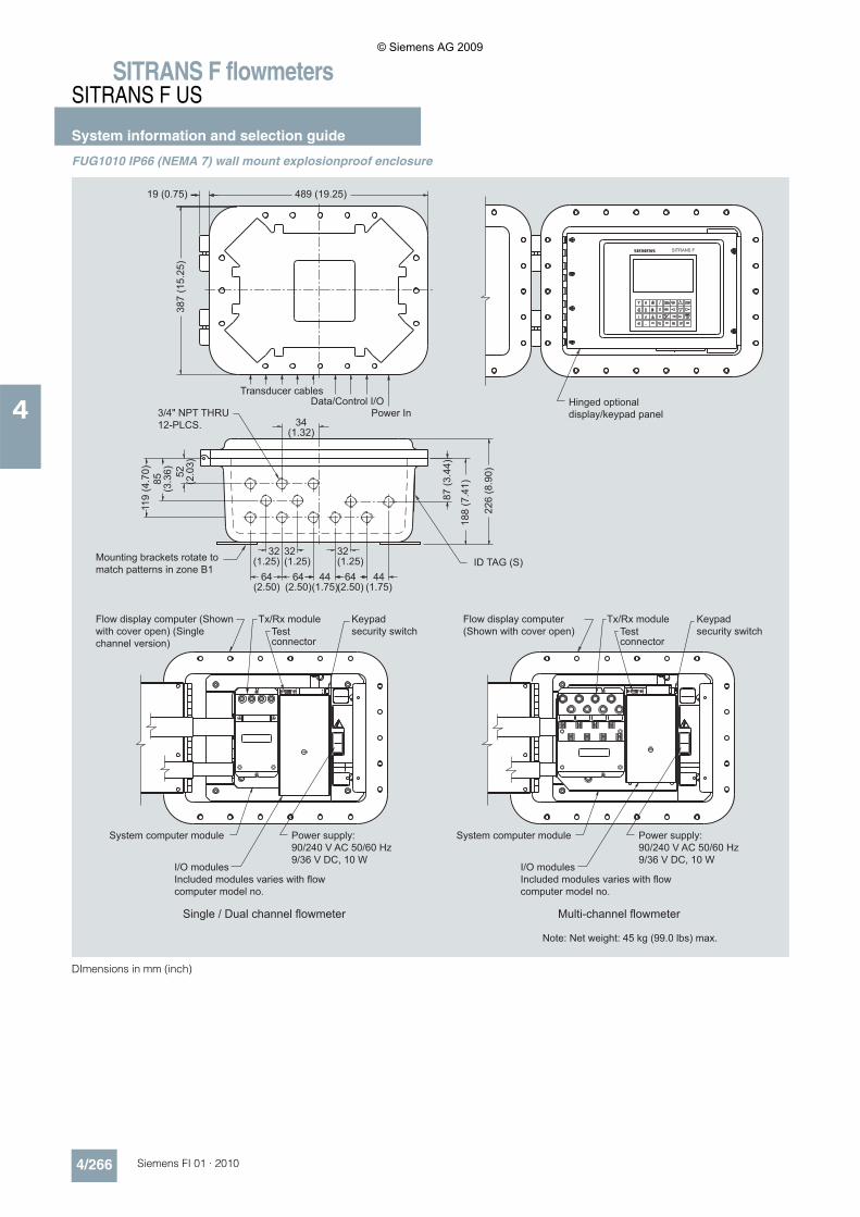
FUG1010 IP66 (NEMA 7) wall mount explosionproof enclosure
DImensions in mm (inch)
Note: Net weight: 45 kg (99.0 lbs) max.
Hinged optional display/keypad panel
Transducer cables
Power InData/Control I/O
Mounting brackets rotate to match patterns in zone B1
3/4" NPT THRU 12-PLCS.
ID TAG (S)
Power supply:90/240 V AC 50/60 Hz9/36 V DC, 10 W
Flow display computer (Shown with cover open)
Flow display computer (Shown with cover open) (Single channel version)
System computer module
Multi-channel flowmeterSingle / Dual channel flowmeter
Tx/Rx module
System computer module
I/O modulesIncluded modules varies with flow computer model no.
I/O modulesIncluded modules varies with flow computer model no.
Keypad security switchTest
connector
Power supply:90/240 V AC 50/60 Hz9/36 V DC, 10 W
Tx/Rx module Keypad security switchTest
connector
s
119
(4.7
0)85
(3
.36) 52
(2.0
3)
44(1.75)
64(2.50)
32(1.25)
32(1.25)
64(2.50)
64(2.50)
32(1.25)
87 (3
.44)
226
(8.9
0)
489 (19.25)19 (0.75)38
7 (1
5.25
)
188
(7.4
1)
34 (1.32)
44(1.75)
© Siemens AG 2009
SITRANS F flowmetersSITRANS F US
System information and selection guide
4/267Siemens FI 01 · 2010
4
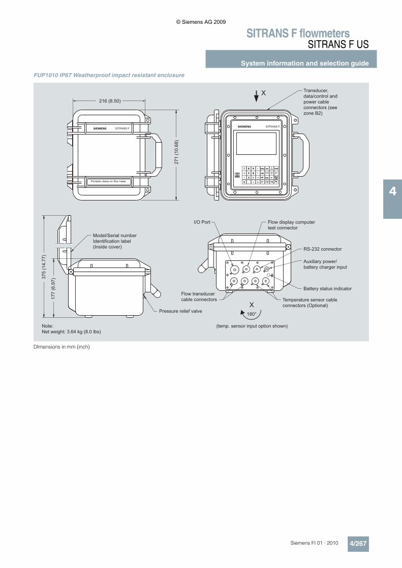
FUP1010 IP67 Weatherproof impact resistant enclosure
DImensions in mm (inch)
Transducer, data/control and power cable connectors (see zone B2)
I/O Port
RS-232 connector
Flow display computer test connector
Auxiliary power/ battery charger input
Battery status indicator
Temperature sensor cable connectors (Optional)
Model/Serial number Identification label (Inside cover)
Note:Net weight: 3.64 kg (8.0 lbs)
Pressure relief valve
Flow transducer cable connectors
(temp. sensor input option shown)
Portable clamp-on flow meter
216 (8.50)
271
(10.
68)
375
(14.
77)
177
(6.9
7)
X
X
180°
© Siemens AG 2009
SITRANS F flowmetersSITRANS F US
System information and selection guide
4/268 Siemens FI 01 · 2010
4
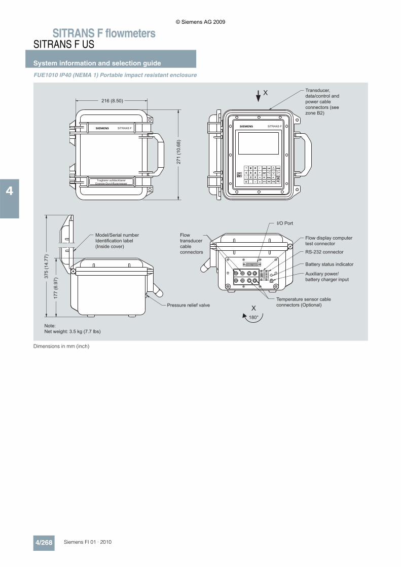
FUE1010 IP40 (NEMA 1) Portable impact resistant enclosure
Dimensions in mm (inch)
Transducer, data/control and power cable connectors (see zone B2)
I/O Port
RS-232 connector
Flow display computer test connector
Auxiliary power/ battery charger input
Battery status indicator
Temperature sensor cable connectors (Optional)
Model/Serial number Identification label (Inside cover)
Note:Net weight: 3.5 kg (7.7 lbs)
Pressure relief valve
Flow transducer cable connectors
Tragbarer aufsteckbarerEnergie-Durchflussmesser
216 (8.50)
271
(10.
68)
375
(14.
77)
177
(6.9
7)
X
X
180°
© Siemens AG 2009
SITRANS F flowmetersSITRANS F US
System information and selection guide
4/269Siemens FI 01 · 2010
4
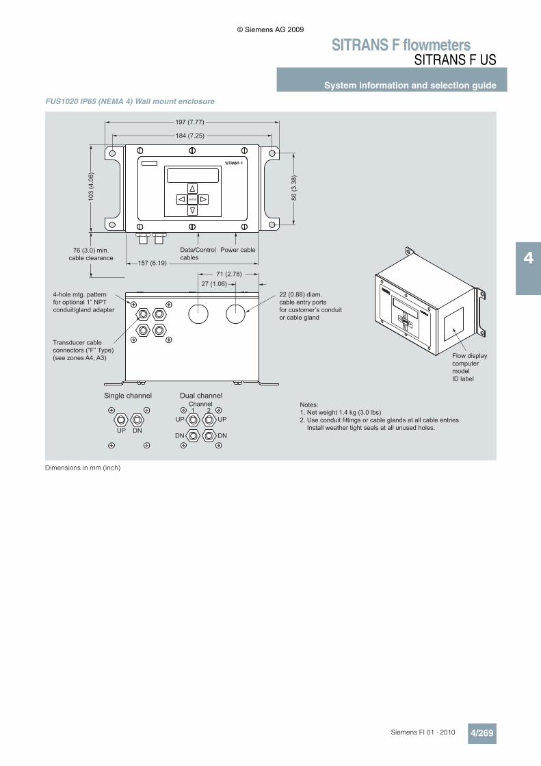
FUS1020 IP65 (NEMA 4) Wall mount enclosure
Dimensions in mm (inch)
76 (3.0) min.cable clearance
Notes:1. Net weight 1.4 kg (3.0 lbs)2. Use conduit fittings or cable glands at all cable entries. Install weather tight seals at all unused holes.
Transducer cableconnectors (“F” Type)(see zones A4, A3)
4-hole mtg. patternfor optional 1” NPTconduit/gland adapter
Data/Controlcables
Power cable
22 (0.88) diam.cable entry portsfor customer’s conduitor cable gland
Flow displaycomputer modelID label
Dual channelSingle channel
UP
Channel1
DN
UP
UP
2
DN DN
© Siemens AG 2009
SITRANS F flowmetersSITRANS F US
SITRANS FUS1010 Standard clamp-on
4/270 Siemens FI 01 · 2010
4
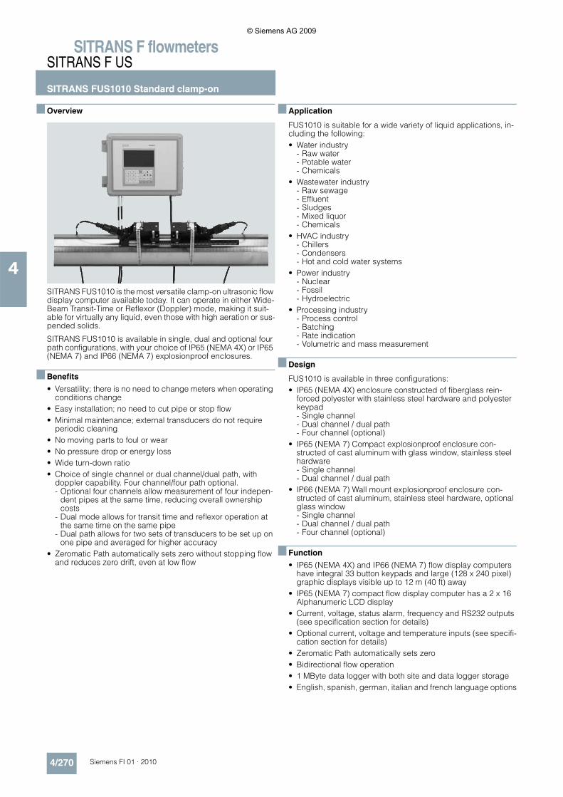
■ Overview
SITRANS FUS1010 is the most versatile clamp-on ultrasonic flow display computer available today. It can operate in either Wide-Beam Transit-Time or Reflexor (Doppler) mode, making it suit-able for virtually any liquid, even those with high aeration or sus-pended solids.
SITRANS FUS1010 is available in single, dual and optional four path configurations, with your choice of IP65 (NEMA 4X) or IP65 (NEMA 7) and IP66 (NEMA 7) explosionproof enclosures.
■ Benefits
• Versatility; there is no need to change meters when operating conditions change
• Easy installation; no need to cut pipe or stop flow• Minimal maintenance; external transducers do not require
periodic cleaning• No moving parts to foul or wear• No pressure drop or energy loss• Wide turn-down ratio• Choice of single channel or dual channel/dual path, with
doppler capability. Four channel/four path optional. - Optional four channels allow measurement of four indepen-
dent pipes at the same time, reducing overall ownership costs
- Dual mode allows for transit time and reflexor operation at the same time on the same pipe
- Dual path allows for two sets of transducers to be set up on one pipe and averaged for higher accuracy
• Zeromatic Path automatically sets zero without stopping flow and reduces zero drift, even at low flow
■ Application
FUS1010 is suitable for a wide variety of liquid applications, in-cluding the following:• Water industry
- Raw water- Potable water- Chemicals
• Wastewater industry - Raw sewage- Effluent- Sludges- Mixed liquor- Chemicals
• HVAC industry - Chillers- Condensers- Hot and cold water systems
• Power industry - Nuclear- Fossil- Hydroelectric
• Processing industry - Process control- Batching- Rate indication- Volumetric and mass measurement
■ Design
FUS1010 is available in three configurations:• IP65 (NEMA 4X) enclosure constructed of fiberglass rein-
forced polyester with stainless steel hardware and polyester keypad- Single channel- Dual channel / dual path- Four channel (optional)
• IP65 (NEMA 7) Compact explosionproof enclosure con-structed of cast aluminum with glass window, stainless steel hardware- Single channel- Dual channel / dual path
• IP66 (NEMA 7) Wall mount explosionproof enclosure con-structed of cast aluminum, stainless steel hardware, optional glass window- Single channel- Dual channel / dual path- Four channel (optional)
■ Function
• IP65 (NEMA 4X) and IP66 (NEMA 7) flow display computers have integral 33 button keypads and large (128 x 240 pixel) graphic displays visible up to 12 m (40 ft) away
• IP65 (NEMA 7) compact flow display computer has a 2 x 16 Alphanumeric LCD display
• Current, voltage, status alarm, frequency and RS232 outputs (see specification section for details)
• Optional current, voltage and temperature inputs (see specifi-cation section for details)
• Zeromatic Path automatically sets zero• Bidirectional flow operation• 1 MByte data logger with both site and data logger storage• English, spanish, german, italian and french language options
© Siemens AG 2009
SITRANS F flowmetersSITRANS F US
SITRANS FUS1010 Standard clamp-on
4/271Siemens FI 01 · 2010
4
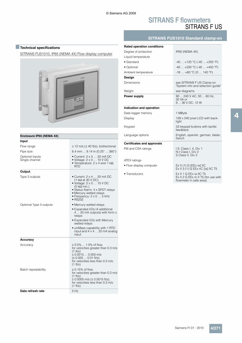
■ Technical specifications
SITRANS FUS1010, IP65 (NEMA 4X) Flow display computer
Enclosure IP65 (NEMA 4X)
Input
Flow range ± 12 m/s (± 40 ft/s), bidirectional
Pipe size 6.4 mm ... 9.14 m (0.25“ ... 360“)
Optional inputsSingle channel
• Current: 2 x 4 … 20 mA DC• Voltage: 2 x 0 … 10 V DC• Temperature: 2 x 4 wire 1 kΩ
RTD
Output
Type 3 outputs • Current: 2 x 4 … 20 mA DC (1 kΩ at 30 V DC)
• Voltage: 2 x 0 … 10 V DC (5 kΩ min.)
• Status Alarm: 4 x SPDT relays• Mercury wetted relays• Frequency: 2 x 0 … 5 kHz• RS232
Optional Type 3 outputs • Mercury wetted relays• Expanded I/Os (4 additional
4 ... 20 mA outputs) with form c relays
• Expanded I/Os with Mercury wetted relays
• uniMass capability with 1 RTD input and 4 x 4 ... 20 mA analog input
Accuracy
Accuracy ± 0.5% ... 1.0% of flow,for velocities greater than 0.3 m/s (1 ft/s)± 0.0015 ... 0.003 m/s (± 0.005 ... 0.01 ft/s),for velocities less than 0.3 m/s (1 ft/s)
Batch repeatability ± 0.15% of flow,for velocities greater than 0.3 m/s (1 ft/s)± 0.0005 m/s (± 0.0015 ft/s),for velocities less than 0.3 m/s (1 ft/s)
Data refresh rate 5 Hz
Rated operation conditions
Degree of protection IP65 (NEMA 4X)
Liquid temperature
• Standard -40 ... +120 °C (-40 ... +250 °F)
• Optional -40 ... +230 °C (-40 ... +450 °F)
Ambient temperature -18 … +60 °C (0 … 140 °F)
Design
Dimensions see SITRANS F US Clamp-on "System info and selection guide"
Weight see diagrams
Power supply 90 ... 240 V AC, 50 ... 60 Hz, 30 VA or9 ... 36 V DC, 12 W
Indication and operation
Data logger memory 1 MByte
Display 128 x 240 pixel LCD with back-light
Keypad 33 keypad buttons with tactile feedback
Language options English, spanish, german, italian, french
Certificates and approvals
FM and CSA ratings I.S. Class I, II, Div 1N-I Class I, Div 2S Class II, Div 2
ATEX ratings
• Flow display computer Ex II (1) G [EEx ia] IICEx II 3 (1) G EEx nC [ia] IIC T5
• Transducers Ex II 1 G EEx ia IIC T5Ex II 2 G EEx m II T5 (for use with flowmeter in safe area)
© Siemens AG 2009
SITRANS F flowmetersSITRANS F US
SITRANS FUS1010 Standard clamp-on
4/272 Siemens FI 01 · 2010
4
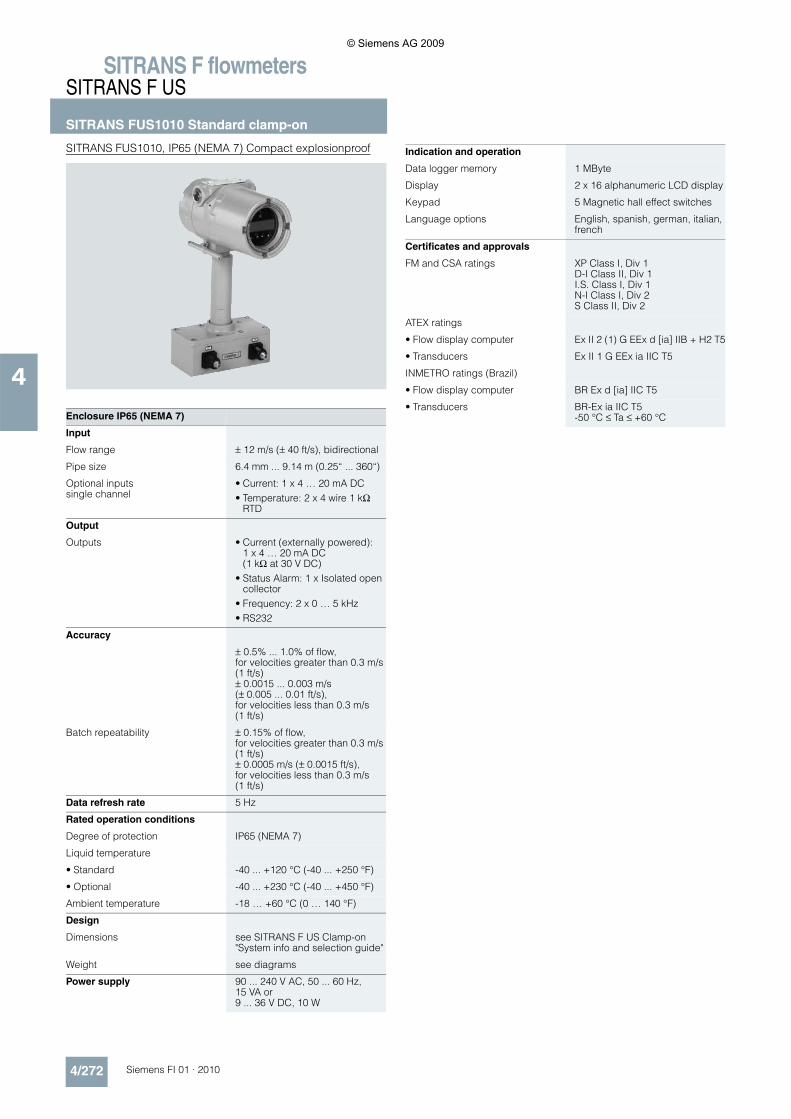
SITRANS FUS1010, IP65 (NEMA 7) Compact explosionproof
Enclosure IP65 (NEMA 7)
Input
Flow range ± 12 m/s (± 40 ft/s), bidirectional
Pipe size 6.4 mm ... 9.14 m (0.25“ ... 360“)
Optional inputssingle channel
• Current: 1 x 4 … 20 mA DC• Temperature: 2 x 4 wire 1 kΩ
RTD
Output
Outputs • Current (externally powered): 1 x 4 … 20 mA DC(1 kΩ at 30 V DC)
• Status Alarm: 1 x Isolated open collector
• Frequency: 2 x 0 … 5 kHz• RS232
Accuracy
± 0.5% ... 1.0% of flow,for velocities greater than 0.3 m/s (1 ft/s)± 0.0015 ... 0.003 m/s (± 0.005 ... 0.01 ft/s),for velocities less than 0.3 m/s (1 ft/s)
Batch repeatability ± 0.15% of flow,for velocities greater than 0.3 m/s (1 ft/s)± 0.0005 m/s (± 0.0015 ft/s),for velocities less than 0.3 m/s (1 ft/s)
Data refresh rate 5 Hz
Rated operation conditions
Degree of protection IP65 (NEMA 7)
Liquid temperature
• Standard -40 ... +120 °C (-40 ... +250 °F)
• Optional -40 ... +230 °C (-40 ... +450 °F)
Ambient temperature -18 … +60 °C (0 … 140 °F)
Design
Dimensions see SITRANS F US Clamp-on "System info and selection guide"
Weight see diagrams
Power supply 90 ... 240 V AC, 50 ... 60 Hz, 15 VA or9 ... 36 V DC, 10 W
Indication and operation
Data logger memory 1 MByte
Display 2 x 16 alphanumeric LCD display
Keypad 5 Magnetic hall effect switches
Language options English, spanish, german, italian, french
Certificates and approvals
FM and CSA ratings XP Class I, Div 1D-I Class II, Div 1I.S. Class I, Div 1N-I Class I, Div 2S Class II, Div 2
ATEX ratings
• Flow display computer Ex II 2 (1) G EEx d [ia] IIB + H2 T5
• Transducers Ex II 1 G EEx ia IIC T5
INMETRO ratings (Brazil)
• Flow display computer BR Ex d [ia] IIC T5
• Transducers BR-Ex ia IIC T5-50 °C ≤ Ta ≤ +60 °C
© Siemens AG 2009
SITRANS F flowmetersSITRANS F US
SITRANS FUS1010 Standard clamp-on
4/273Siemens FI 01 · 2010
4
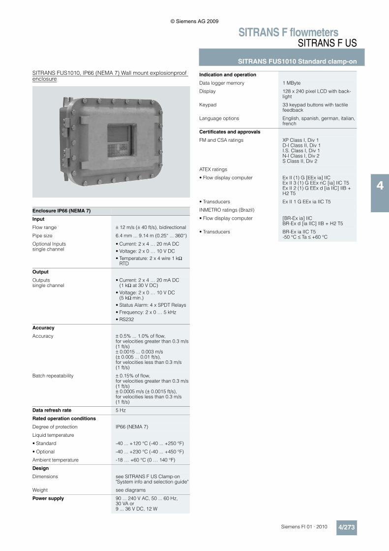
SITRANS FUS1010, IP66 (NEMA 7) Wall mount explosionproof enclosure
Enclosure IP66 (NEMA 7)
Input
Flow range ± 12 m/s (± 40 ft/s), bidirectional
Pipe size 6.4 mm ... 9.14 m (0.25“ ... 360“)
Optional Inputssingle channel
• Current: 2 x 4 … 20 mA DC• Voltage: 2 x 0 … 10 V DC• Temperature: 2 x 4 wire 1 kΩ
RTD
Output
Outputssingle channel
• Current: 2 x 4 … 20 mA DC (1 kΩ at 30 V DC)
• Voltage: 2 x 0 … 10 V DC (5 kΩ min.)
• Status Alarm: 4 x SPDT Relays• Frequency: 2 x 0 … 5 kHz• RS232
Accuracy
Accuracy ± 0.5% ... 1.0% of flow,for velocities greater than 0.3 m/s (1 ft/s)± 0.0015 ... 0.003 m/s (± 0.005 ... 0.01 ft/s),for velocities less than 0.3 m/s (1 ft/s)
Batch repeatability ± 0.15% of flow,for velocities greater than 0.3 m/s (1 ft/s)± 0.0005 m/s (± 0.0015 ft/s),for velocities less than 0.3 m/s (1 ft/s)
Data refresh rate 5 Hz
Rated operation conditions
Degree of protection IP66 (NEMA 7)
Liquid temperature
• Standard -40 ... +120 °C (-40 ... +250 °F)
• Optional -40 ... +230 °C (-40 ... +450 °F)
Ambient temperature -18 … +60 °C (0 … 140 °F)
Design
Dimensions see SITRANS F US Clamp-on "System info and selection guide"
Weight see diagrams
Power supply 90 ... 240 V AC, 50 ... 60 Hz, 30 VA or9 ... 36 V DC, 12 W
Indication and operation
Data logger memory 1 MByte
Display 128 x 240 pixel LCD with back-light
Keypad 33 keypad buttons with tactile feedback
Language options English, spanish, german, italian, french
Certificates and approvals
FM and CSA ratings XP Class I, Div 1D-I Class II, Div 1I.S. Class I, Div 1N-I Class I, Div 2S Class II, Div 2
ATEX ratings
• Flow display computer Ex II (1) G [EEx ia] IICEx II 3 (1) G EEx nC [ia] IIC T5Ex II 2 (1) G EEx d [ia IIC] IIB + H2 T5
• Transducers Ex II 1 G EEx ia IIC T5
INMETRO ratings (Brazil)
• Flow display computer [BR-Ex ia] IICBR-Ex d [ia IIC] IIB + H2 T5
• Transducers BR-Ex ia IIC T5-50 °C ≤ Ta ≤ +60 °C
© Siemens AG 2009
SITRANS F flowmetersSITRANS F US
SITRANS FUS1010 Standard clamp-on
4/274 Siemens FI 01 · 2010
4
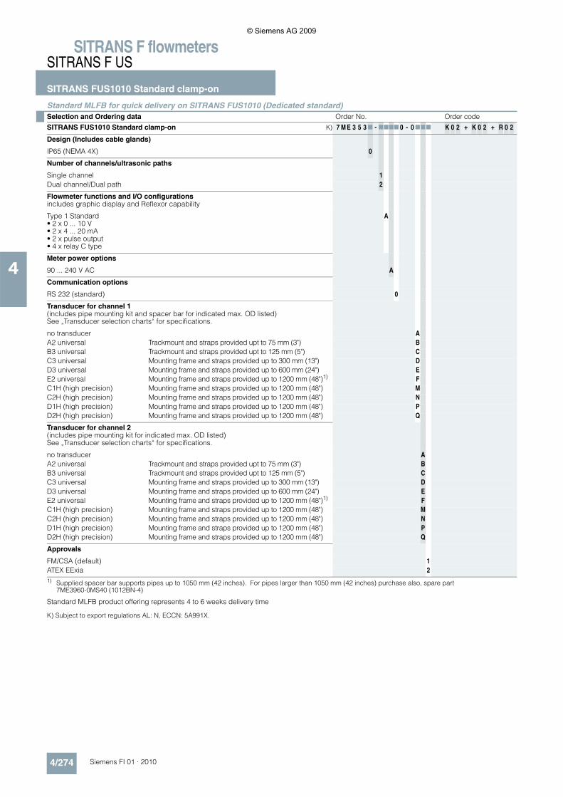
Standard MLFB for quick delivery on SITRANS FUS1010 (Dedicated standard)
K) Subject to export regulations AL: N, ECCN: 5A991X.
Selection and Ordering data Order No. Order code
SITRANS FUS1010 Standard clamp-on K) 7 M E 3 5 3 7 - 7777 0 - 0 777 K 0 2 + K 0 2 + R 0 2
Design (Includes cable glands)
IP65 (NEMA 4X) 0
Number of channels/ultrasonic paths
Single channel 1Dual channel/Dual path 2
Flowmeter functions and I/O configurationsincludes graphic display and Reflexor capability
Type 1 Standard• 2 x 0 ... 10 V• 2 x 4 ... 20 mA• 2 x pulse output• 4 x relay C type
A
Meter power options
90 ... 240 V AC A
Communication options
RS 232 (standard) 0
Transducer for channel 1(includes pipe mounting kit and spacer bar for indicated max. OD listed) See „Transducer selection charts“ for specifications.
no transducer AA2 universal Trackmount and straps provided upt to 75 mm (3") BB3 universal Trackmount and straps provided upt to 125 mm (5") CC3 universal Mounting frame and straps provided up to 300 mm (13") DD3 universal Mounting frame and straps provided up to 600 mm (24") EE2 universal Mounting frame and straps provided up to 1200 mm (48")1) FC1H (high precision) Mounting frame and straps provided up to 1200 mm (48") MC2H (high precision) Mounting frame and straps provided up to 1200 mm (48") ND1H (high precision) Mounting frame and straps provided up to 1200 mm (48") PD2H (high precision) Mounting frame and straps provided up to 1200 mm (48") Q
Transducer for channel 2(includes pipe mounting kit for indicated max. OD listed)See „Transducer selection charts“ for specifications.
no transducer AA2 universal Trackmount and straps provided upt to 75 mm (3") BB3 universal Trackmount and straps provided upt to 125 mm (5") CC3 universal Mounting frame and straps provided up to 300 mm (13") DD3 universal Mounting frame and straps provided up to 600 mm (24") EE2 universal Mounting frame and straps provided up to 1200 mm (48")1) FC1H (high precision) Mounting frame and straps provided up to 1200 mm (48") MC2H (high precision) Mounting frame and straps provided up to 1200 mm (48") ND1H (high precision) Mounting frame and straps provided up to 1200 mm (48") PD2H (high precision) Mounting frame and straps provided up to 1200 mm (48") Q
Approvals
FM/CSA (default) 1ATEX EExia 21) Supplied spacer bar supports pipes up to 1050 mm (42 inches). For pipes larger than 1050 mm (42 inches) purchase also, spare part
7ME3960-0MS40 (1012BN-4)
Standard MLFB product offering represents 4 to 6 weeks delivery time
© Siemens AG 2009
SITRANS F flowmetersSITRANS F US
SITRANS FUS1010 Standard clamp-on
4/275Siemens FI 01 · 2010
4
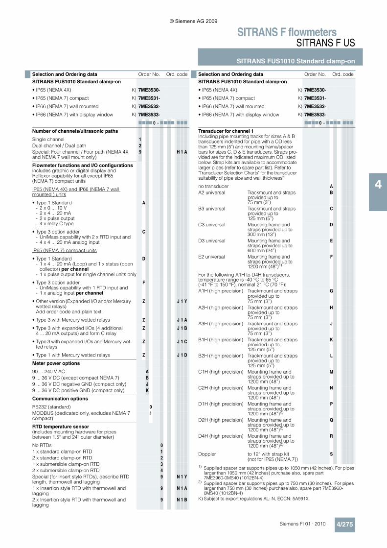
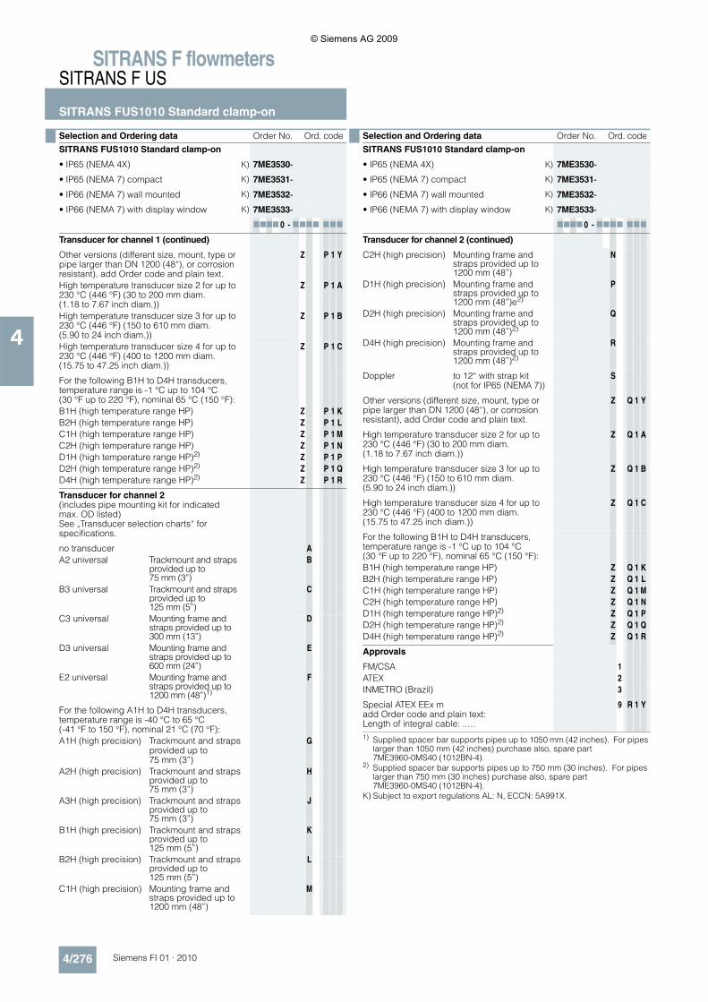
Selection and Ordering data Order No. Ord. code
SITRANS FUS1010 Standard clamp-on
• IP65 (NEMA 4X) K) 7ME3530-
• IP65 (NEMA 7) compact K) 7ME3531-
• IP66 (NEMA 7) wall mounted K) 7ME3532-
• IP66 (NEMA 7) with display window K) 7ME3533-7777 0 - 7777 777
Number of channels/ultrasonic paths
Single channel 1Dual channel / Dual path 2Special: Four channel / Four path (NEMA 4X and NEMA 7 wall mount only)
9 H 1 A
Flowmeter functions and I/O configurationsincludes graphic or digital display andReflexor capability for all except IP65(NEMA 7) compact units
IP65 (NEMA 4X) and IP66 (NEMA 7 wall mounted ) units
• Type 1 Standard- 2 x 0 ... 10 V- 2 x 4 ... 20 mA- 2 x pulse output- 4 x relay C type
A
• Type 3 option adder- UniMass capability with 2 x RTD input and - 4 x 4 ... 20 mA analog input
C
IP65 (NEMA 7) compact units
• Type 1 Standard- 1 x 4 ... 20 mA (Loop) and 1 x status (open
collector) per channel- 1 x pulse output for single channel units only
D
• Type 3 option adder- UniMass capability with 1 RTD input and- 1 x analog input per channel
F
• Other version (Expanded I/O and/or Mercury wetted relays)Add order code and plain text.
Z J 1 Y
• Type 3 with Mercury wetted relays Z J 1 A
• Type 3 with expanded I/Os (4 additional 4 ... 20 mA outputs) and form C relay
Z J 1 B
• Type 3 with expanded I/Os and Mercury wet-ted relays
Z J 1 C
• Type 1 with Mercury wetted relays Z J 1 D
Meter power options
90 ... 240 V AC A9 ... 36 V DC (except compact NEMA 7) B9 ... 36 V DC negative GND (compact only) J9 ... 36 V DC positive GND (compact only) K
Communication options
RS232 (standard) 0MODBUS (dedicated only, excludes NEMA 7 compact)
1
RTD temperature sensor(includes mounting hardware for pipes between 1.5“ and 24“ outer diameter)
No RTDs 01 x standard clamp-on RTD 12 x standard clamp-on RTD 21 x submersible clamp-on RTD 32 x submersible clamp-on RTD 4Special (for insert style RTDs), describe RTD length, thermowell and lagging
9 N 1 Y
1 x Insertion style RTD with thermowell and lagging
9 N 1 A
2 x Insertion style RTD with thermowell and lagging
9 N 1 B
Transducer for channel 1Including pipe mounting tracks for sizes A & B transducers indented for pipe with a OD less than 125 mm (5") and mounting frame/spacer bars for sizes C, D & E transducers. Straps pro-vided are for the indicated maximum OD listed below. Strap kits are available to accommodate larger pipes (refer to spare part list). Refer to "Transducer Selection Charts" for the transducer suitability of pipe size and wall thickness"
no transducer AA2 universal Trackmount and straps
provided up to 75 mm (3”)
B
B3 universal Trackmount and straps provided up to 125 mm (5”)
C
C3 universal Mounting frame and straps provided up to 300 mm (13”)
D
D3 universal Mounting frame and straps provided up to 600 mm (24”)
E
E2 universal Mounting frame and straps provided up to 1200 mm (48”)1)
F
For the following A1H to D4H transducers, temperature range is -40 °C to 65 °C(-41 °F to 150 °F), nominal 21 °C (70 °F):A1H (high precision) Trackmount and straps
provided up to 75 mm (3”)
G
A2H (high precision) Trackmount and strapsprovided up to 75 mm (3”)
H
A3H (high precision) Trackmount and strapsprovided up to 75 mm (3”)
J
B1H (high precision) Trackmount and strapsprovided up to 125 mm (5”)
K
B2H (high precision) Trackmount and strapsprovided up to 125 mm (5”)
L
C1H (high precision) Mounting frame and straps provided up to 1200 mm (48”)
M
C2H (high precision) Mounting frame and straps provided up to 1200 mm (48”)
N
D1H (high precision) Mounting frame and straps provided up to 1200 mm (48”)2)
P
D2H (high precision) Mounting frame and straps provided up to 1200 mm (48”)2)
Q
D4H (high precision) Mounting frame and straps provided up to 1200 mm (48”)2)
R
Doppler to 12“ with strap kit(not for IP65 (NEMA 7))
S
1) Supplied spacer bar supports pipes up to 1050 mm (42 inches). For pipes larger than 1050 mm (42 inches) purchase also, spare part 7ME3960-0MS40 (1012BN-4)
2) Supplied spacer bar supports pipes up to 750 mm (30 inches). For pipes larger than 750 mm (30 inches) purchase also, spare part 7ME3960-0MS40 (1012BN-4)
K) Subject to export regulations AL: N, ECCN: 5A991X.
Selection and Ordering data Order No. Ord. code
SITRANS FUS1010 Standard clamp-on
• IP65 (NEMA 4X) K) 7ME3530-
• IP65 (NEMA 7) compact K) 7ME3531-
• IP66 (NEMA 7) wall mounted K) 7ME3532-
• IP66 (NEMA 7) with display window K) 7ME3533-7777 0 - 7777 777
© Siemens AG 2009
SITRANS F flowmetersSITRANS F US
SITRANS FUS1010 Standard clamp-on
4/276 Siemens FI 01 · 2010
4
Transducer for channel 1 (continued)
Other versions (different size, mount, type or pipe larger than DN 1200 (48“), or corrosion resistant), add Order code and plain text.
Z P 1 Y
High temperature transducer size 2 for up to 230 °C (446 °F) (30 to 200 mm diam. (1.18 to 7.67 inch diam.))
Z P 1 A
High temperature transducer size 3 for up to 230 °C (446 °F) (150 to 610 mm diam. (5.90 to 24 inch diam.))
Z P 1 B
High temperature transducer size 4 for up to 230 °C (446 °F) (400 to 1200 mm diam. (15.75 to 47.25 inch diam.))
Z P 1 C
For the following B1H to D4H transducers, temperature range is -1 °C up to 104 °C (30 °F up to 220 °F), nominal 65 °C (150 °F):B1H (high temperature range HP) Z P 1 KB2H (high temperature range HP) Z P 1 LC1H (high temperature range HP) Z P 1 MC2H (high temperature range HP) Z P 1 ND1H (high temperature range HP)2) Z P 1 PD2H (high temperature range HP)2) Z P 1 QD4H (high temperature range HP)2) Z P 1 R
Transducer for channel 2(includes pipe mounting kit for indicated max. OD listed)See „Transducer selection charts“ for specifications.
no transducer AA2 universal Trackmount and straps
provided up to 75 mm (3”)
B
B3 universal Trackmount and straps provided up to 125 mm (5”)
C
C3 universal Mounting frame and straps provided up to 300 mm (13”)
D
D3 universal Mounting frame and straps provided up to 600 mm (24”)
E
E2 universal Mounting frame and straps provided up to 1200 mm (48”)1)
F
For the following A1H to D4H transducers, temperature range is -40 °C to 65 °C (-41 °F to 150 °F), nominal 21 °C (70 °F):A1H (high precision) Trackmount and straps
provided up to 75 mm (3”)
G
A2H (high precision) Trackmount and strapsprovided up to 75 mm (3”)
H
A3H (high precision) Trackmount and strapsprovided up to 75 mm (3”)
J
B1H (high precision) Trackmount and strapsprovided up to 125 mm (5”)
K
B2H (high precision) Trackmount and strapsprovided up to 125 mm (5”)
L
C1H (high precision) Mounting frame and straps provided up to 1200 mm (48”)
M
Selection and Ordering data Order No. Ord. code
SITRANS FUS1010 Standard clamp-on
• IP65 (NEMA 4X) K) 7ME3530-
• IP65 (NEMA 7) compact K) 7ME3531-
• IP66 (NEMA 7) wall mounted K) 7ME3532-
• IP66 (NEMA 7) with display window K) 7ME3533-7777 0 - 7777 777
Transducer for channel 2 (continued)
C2H (high precision) Mounting frame and straps provided up to 1200 mm (48”)
N
D1H (high precision) Mounting frame and straps provided up to 1200 mm (48”)e2)
P
D2H (high precision) Mounting frame and straps provided up to 1200 mm (48”)2)
Q
D4H (high precision) Mounting frame and straps provided up to 1200 mm (48”)2)
R
Doppler to 12“ with strap kit (not for IP65 (NEMA 7))
S
Other versions (different size, mount, type or pipe larger than DN 1200 (48“), or corrosion resistant), add Order code and plain text.
Z Q 1 Y
High temperature transducer size 2 for up to 230 °C (446 °F) (30 to 200 mm diam. (1.18 to 7.67 inch diam.))
Z Q 1 A
High temperature transducer size 3 for up to 230 °C (446 °F) (150 to 610 mm diam. (5.90 to 24 inch diam.))
Z Q 1 B
High temperature transducer size 4 for up to 230 °C (446 °F) (400 to 1200 mm diam. (15.75 to 47.25 inch diam.))
Z Q 1 C
For the following B1H to D4H transducers, temperature range is -1 °C up to 104 °C (30 °F up to 220 °F), nominal 65 °C (150 °F):B1H (high temperature range HP) Z Q 1 KB2H (high temperature range HP) Z Q 1 LC1H (high temperature range HP) Z Q 1 MC2H (high temperature range HP) Z Q 1 ND1H (high temperature range HP)2) Z Q 1 PD2H (high temperature range HP)2) Z Q 1 QD4H (high temperature range HP)2) Z Q 1 R
Approvals
FM/CSA 1ATEX 2INMETRO (Brazil) 3
Special ATEX EEx madd Order code and plain text:Length of integral cable: .....
9 R 1 Y
1) Supplied spacer bar supports pipes up to 1050 mm (42 inches). For pipes larger than 1050 mm (42 inches) purchase also, spare part 7ME3960-0MS40 (1012BN-4).
2) Supplied spacer bar supports pipes up to 750 mm (30 inches). For pipes larger than 750 mm (30 inches) purchase also, spare part 7ME3960-0MS40 (1012BN-4).
K) Subject to export regulations AL: N, ECCN: 5A991X.
Selection and Ordering data Order No. Ord. code
SITRANS FUS1010 Standard clamp-on
• IP65 (NEMA 4X) K) 7ME3530-
• IP65 (NEMA 7) compact K) 7ME3531-
• IP66 (NEMA 7) wall mounted K) 7ME3532-
• IP66 (NEMA 7) with display window K) 7ME3533-7777 0 - 7777 777
© Siemens AG 2009
SITRANS F flowmetersSITRANS F US
SITRANS FUS1010 Standard clamp-on
4/277Siemens FI 01 · 2010
4
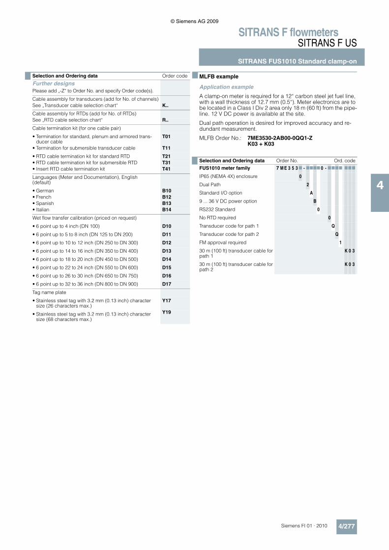
■ MLFB example
Application example
A clamp-on meter is required for a 12“ carbon steel jet fuel line, with a wall thickness of 12.7 mm (0.5“). Meter electronics are to be located in a Class I Div 2 area only 18 m (60 ft) from the pipe-line. 12 V DC power is available at the site.
Dual path operation is desired for improved accuracy and re-dundant measurement.
MLFB Order No.: 7ME3530-2AB00-0QQ1-ZK03 + K03
Selection and Ordering data Order code
Further designsPlease add „-Z“ to Order No. and specify Order code(s).
Cable assembly for transducers (add for No. of channels)See „Transducer cable selection chart“ K..
Cable assembly for RTDs (add for No. of RTDs)See „RTD cable selection chart“ R..
Cable termination kit (for one cable pair)
• Termination for standard, plenum and armored trans-ducer cable
T01
• Termination for submersible transducer cable T11
• RTD cable termination kit for standard RTD T21• RTD cable termination kit for submersible RTD T31• Insert RTD cable termination kit T41
Languages (Meter and Documentation), English (default)
• German B10• French B12• Spanish B13• Italian B14
Wet flow transfer calibration (priced on request)
• 6 point up to 4 inch (DN 100) D10
• 6 point up to 5 to 8 inch (DN 125 to DN 200) D11
• 6 point up to 10 to 12 inch (DN 250 to DN 300) D12
• 6 point up to 14 to 16 inch (DN 350 to DN 400) D13
• 6 point up to 18 to 20 inch (DN 450 to DN 500) D14
• 6 point up to 22 to 24 inch (DN 550 to DN 600) D15
• 6 point up to 26 to 30 inch (DN 650 to DN 750) D16
• 6 point up to 32 to 36 inch (DN 800 to DN 900) D17
Tag name plate
• Stainless steel tag with 3.2 mm (0.13 inch) character size (26 characters max.)
Y17
• Stainless steel tag with 3.2 mm (0.13 inch) character size (68 characters max.)
Y19
Selection and Ordering data Order No. Ord. code
FUS1010 meter family 7 M E 3 5 3 7 - 7777 0 - 7777 777
IP65 (NEMA 4X) enclosure 0
Dual Path 2
Standard I/O option A
9 ... 36 V DC power option B
RS232 Standard 0
No RTD required 0
Transducer code for path 1 Q
Transducer code for path 2 Q
FM approval required 1
30 m (100 ft) transducer cable for path 1
K 0 3
30 m (100 ft) transducer cable for path 2
K 0 3
© Siemens AG 2009
SITRANS F flowmetersSITRANS F US
SITRANS FUS1010 Standard clamp-on
4/278 Siemens FI 01 · 2010
4
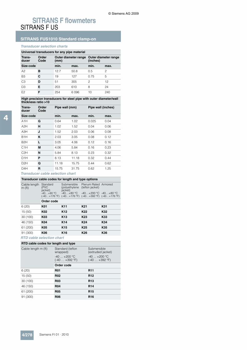
Transducer selection charts
Transducer cable selection chart
RTD cable selection chart
Universal transducers for any pipe material
Trans-ducer
Order Code
Outer diameter range (mm)
Outer diameter range (inches)
Size code min. max. min. max.
A2 B 12.7 50.8 0.5 2
B3 C 19 127 0.75 5
C3 D 51 305 2 12
D3 E 203 610 8 24
E2 F 254 6 096 10 240
High precision transducers for steel pipe with outer diameter/wall thickness ratio >10
Trans-ducer
Order Code
Pipe wall (mm) Pipe wall (inches)
Size code min. max. min. max.
A1H G 0.64 1.02 0.025 0.04
A2H H 1.02 1.52 0.04 0.06
A3H J 1.52 2.03 0.06 0.08
B1H K 2.03 3.05 0.08 0.12
B2H L 3.05 4.06 0.12 0.16
C1H M 4.06 5.84 0.16 0.23
C2H N 5.84 8.13 0.23 0.32
D1H P 8.13 11.18 0.32 0.44
D2H Q 11.18 15.75 0.44 0.62
D4H R 15.75 31.75 0.62 1.25
Transducer cable codes for length and type options
Cable length m (ft)
Standard (PVCjacket)-40…+80 °C(-40…+176 °F)
Submersible(polyethylene jacket)-40…+80 °C(-40…+176 °F)
Plenum Rated(teflon jacket)
-40…+200 °C(-40…+392 °F)
Armored
-40…+80 °C(-40…+176 °F)
Order code
6 (20) K01 K11 K21 K31
15 (50) K02 K12 K22 K32
30 (100) K03 K13 K23 K33
46 (150) K04 K14 K24 K34
61 (200) K05 K15 K25 K35
91 (300) K06 K16 K26 K36
RTD cable codes for length and type
Cable length m (ft) Standard (teflon wrapped)-40 ... +200 °C(-40 … +392 °F)
Submersible (extruded jacket)-40 ... +200 °C(-40 … +392 °F)
Order code
6 (20) R01 R11
15 (50) R02 R12
30 (100) R03 R13
46 (150) R04 R14
61 (200) R05 R15
91 (300) R06 R16
© Siemens AG 2009