Embed Size (px)
Citation preview

Electromagnetic flowmetersSITRANS F M MAG 5000/6000
Operating Instructions
12/2013Edition
Answers for industry.
SITRANS F


SITRANS F M MAG 5000/6000
?
___________________
___________________
___________________
___________________
___________________
___________________
___________________
___________________
___________________
___________________
___________________
___________________
___________________
___________________
___________________
SITRANS F
Flowmeters SITRANS F M MAG 5000/6000
Operating Instructions
Electromagnetic flow transmitter designed for use with flow sensor types MAG 1100/1100 F/3100/3100 P/5100 W Compact and remote installation
12/2013 A5E02338368-002
Introduction
1
Safety notes
2
Description
3
Installing/Mounting
4
Connecting
5
Commissioning
6
Functions
7
Alarm, error, and system messages
8
Service and maintenance
9
Troubleshooting/FAQs
10
Technical data
11
Spare parts/Accessories
12
Menu diagrams
A
Factory settings
B
Approvals/Certificates
C

Siemens AG
Industry Sector
Postfach 48 48
90026 NÜRNBERG
GERMANY
Order number: A5E02338368
Ⓟ 12/2013 Technical data subject to change
Copyright © Siemens AG 2013.
All rights reserved
Legal information
Warning notice system
This manual contains notices you have to observe in order to ensure your personal safety, as well as to prevent
damage to property. The notices referring to your personal safety are highlighted in the manual by a safety alert
symbol, notices referring only to property damage have no safety alert symbol. These notices shown below are
graded according to the degree of danger.
DANGER
indicates that death or severe personal injury will result if proper precautions are not taken.
WARNING
indicates that death or severe personal injury may result if proper precautions are not taken.
CAUTION
indicates that minor personal injury can result if proper precautions are not taken.
NOTICE
indicates that property damage can result if proper precautions are not taken.
If more than one degree of danger is present, the warning notice representing the highest degree of danger will
be used. A notice warning of injury to persons with a safety alert symbol may also include a warning relating to
property damage.
Qualified Personnel
The product/system described in this documentation may be operated only by personnel qualified for the specific
task in accordance with the relevant documentation, in particular its warning notices and safety instructions.
Qualified personnel are those who, based on their training and experience, are capable of identifying risks and
avoiding potential hazards when working with these products/systems.
Proper use of Siemens products
Note the following:
WARNING
Siemens products may only be used for the applications described in the catalog and in the relevant technical
documentation. If products and components from other manufacturers are used, these must be recommended
or approved by Siemens. Proper transport, storage, installation, assembly, commissioning, operation and
maintenance are required to ensure that the products operate safely and without any problems. The permissible
ambient conditions must be complied with. The information in the relevant documentation must be observed.
Trademarks
All names identified by ® are registered trademarks of Siemens AG. The remaining trademarks in this publication
may be trademarks whose use by third parties for their own purposes could violate the rights of the owner.
Disclaimer of Liability
We have reviewed the contents of this publication to ensure consistency with the hardware and software
described. Since variance cannot be precluded entirely, we cannot guarantee full consistency. However, the
information in this publication is reviewed regularly and any necessary corrections are included in subsequent
editions.
SITRANS F M MAG 5000/6000
Operating Instructions, 12/2013, A5E02338368-002 3
Table of contents
1 Introduction ................................................................................................................................................ 7
1.1 Preface ........................................................................................................................................... 7
1.2 Items supplied ................................................................................................................................ 7
1.3 History ............................................................................................................................................ 8
1.4 Further Information ........................................................................................................................ 9
2 Safety notes ............................................................................................................................................. 11
2.1 Laws and directives ..................................................................................................................... 11
2.2 Installation in hazardous location ................................................................................................. 12
3 Description ............................................................................................................................................... 15
3.1 System components .................................................................................................................... 15
3.2 Operating principle ....................................................................................................................... 15
3.3 Applications .................................................................................................................................. 15
3.4 Features ....................................................................................................................................... 16
3.5 MAG 5000/MAG 6000 versions ................................................................................................... 17
4 Installing/Mounting ................................................................................................................................... 19
4.1 Introduction .................................................................................................................................. 19
4.2 Installation conditions ................................................................................................................... 20
4.3 MAG 5000/6000 compact ............................................................................................................ 22
4.4 Remote installation ...................................................................................................................... 24
4.5 MAG 5000/6000 CT ..................................................................................................................... 28
4.5.1 Installing hardware key ................................................................................................................ 29
4.5.2 Seal device ................................................................................................................................... 29
4.5.3 Installation conditions ................................................................................................................... 31
4.5.3.1 MI-001 .......................................................................................................................................... 31
4.5.3.2 PTB K7.2 ...................................................................................................................................... 31
4.6 Turning transmitter/keypad .......................................................................................................... 31
5 Connecting .............................................................................................................................................. 35
5.1 Electrical connection .................................................................................................................... 36
5.2 Electrical connection PTB K7.2 .................................................................................................... 38
5.3 Connection of add-on modules .................................................................................................... 38
6 Commissioning ........................................................................................................................................ 39
6.1 MAG 5000/6000 Blind .................................................................................................................. 39
6.2 Local user interface ...................................................................................................................... 40

Table of contents
SITRANS F M MAG 5000/6000
4 Operating Instructions, 12/2013, A5E02338368-002
6.3 Menu structure ............................................................................................................................ 41
6.4 Changing password .................................................................................................................... 42
6.5 Changing basic settings .............................................................................................................. 43
6.6 Changing operator menu setup .................................................................................................. 45
6.7 Changing language ..................................................................................................................... 46
7 Functions ................................................................................................................................................. 47
7.1 Output settings ............................................................................................................................ 47
7.2 External input .............................................................................................................................. 49
7.3 Sensor characteristics ................................................................................................................. 49
7.4 Reset mode ................................................................................................................................. 49
7.5 Service mode .............................................................................................................................. 51
7.6 MAG 5000 CT and MAG 6000 CT settings ................................................................................. 51
7.7 MAG 6000 SV ............................................................................................................................. 52
8 Alarm, error, and system messages ........................................................................................................ 53
8.1 Diagnostics .................................................................................................................................. 53
8.2 List of error numbers ................................................................................................................... 55
9 Service and maintenance ........................................................................................................................ 57
9.1 Transmitter check list .................................................................................................................. 57
9.2 Technical support ........................................................................................................................ 58
9.3 Return procedures ...................................................................................................................... 59
9.4 Recalibration ............................................................................................................................... 60
10 Troubleshooting/FAQs ............................................................................................................................. 61
11 Technical data ......................................................................................................................................... 63
11.1 Technical specifications .............................................................................................................. 63
11.2 Accuracy ...................................................................................................................................... 66
11.3 Output characteristics ................................................................................................................. 68
11.4 Cable data ................................................................................................................................... 71
11.5 Cable requirements ..................................................................................................................... 72
12 Spare parts/Accessories .......................................................................................................................... 73
12.1 Ordering ...................................................................................................................................... 73
12.2 Accessories ................................................................................................................................. 73
12.3 Spare parts .................................................................................................................................. 74
12.4 Sun shield.................................................................................................................................... 74
A Menu diagrams ........................................................................................................................................ 75
A.1 Transmitter menu overview ......................................................................................................... 75

Table of contents
SITRANS F M MAG 5000/6000
Operating Instructions, 12/2013, A5E02338368-002 5
A.2 Basic settings ............................................................................................................................... 76
A.3 Current output .............................................................................................................................. 77
A.4 Digital output - pulse .................................................................................................................... 78
A.5 Digital output - frequency ............................................................................................................. 78
A.6 Error level ..................................................................................................................................... 78
A.7 Error number ................................................................................................................................ 79
A.8 Direction/limit ................................................................................................................................ 79
A.9 Batch ............................................................................................................................................ 79
A.10 External input ............................................................................................................................... 80
A.11 Sensor characteristics .................................................................................................................. 81
A.12 Reset mode .................................................................................................................................. 82
A.13 Reset mode - MAG 6000 SV ....................................................................................................... 83
A.14 Service mode ............................................................................................................................... 84
A.15 Operator menu setup ................................................................................................................... 85
A.16 Product identity ............................................................................................................................ 86
A.17 Add-on communication module ................................................................................................... 87
A.18 Cleaning ....................................................................................................................................... 87
A.19 MAG 5000/6000 CT menu overview ............................................................................................ 88
A.20 Change password ........................................................................................................................ 89
B Factory settings ....................................................................................................................................... 91
B.1 Transmitter factory settings .......................................................................................................... 91
B.2 50 Hz Dimension dependent ........................................................................................................ 93
B.3 60 Hz Dimension dependent ........................................................................................................ 94
B.4 50 Hz Dimension dependent batch and pulse output settings .................................................... 96
B.5 60 Hz Dimension dependent batch and pulse output settings .................................................... 97
C Approvals/Certificates .............................................................................................................................. 99
Index ...................................................................................................................................................... 101

Table of contents
SITRANS F M MAG 5000/6000
6 Operating Instructions, 12/2013, A5E02338368-002

SITRANS F M MAG 5000/6000
Operating Instructions, 12/2013, A5E02338368-002 7
1 Introduction 1
1.1 Preface
These instructions contain all the information you need for using the device.
The instructions are aimed at persons mechanically installing the device, connecting it
electronically, configuring the parameters and commissioning it as well as service and
maintenance engineers.
Note
It is the responsibility of the customer that the instructions and directions provided in the
manual are read, understood and followed by the relevant personnel before installing the
device.
1.2 Items supplied
SITRANS F M MAG 5000/6000 transmitter
Calibration report
SITRANS F literature CD
Quick start guide
Inspection
1. Check for mechanical damage due to possible improper handling during shipment. All
claims for damage are to be made promptly to the shipper.
2. Make sure the scope of delivery, and the information on the type plate corresponds to the
ordering information

Introduction
1.3 History
SITRANS F M MAG 5000/6000
8 Operating Instructions, 12/2013, A5E02338368-002
Device identification
① Code number
② Power supply
③ Enclosure rating
④ Ambient temperature
⑤ Approvals
Figure 1-1 MAG 5000/6000 nameplate
1.3 History
This document describes:
● SITRANS F MAG 5000 and MAG 6000 transmitters (standard version).
● Optional versions:
– MAG 5000 Blind and MAG 6000 Blind
– MAG 5000 CT and MAG 6000 CT
– MAG 6000 SV

Introduction
1.4 Further Information
SITRANS F M MAG 5000/6000
Operating Instructions, 12/2013, A5E02338368-002 9
Documentation history
The contents of these instructions are regularly reviewed and corrections are included in
subsequent editions. We welcome all suggestions for improvement.
The following table shows the most important changes in the documentation compared to
each previous edition.
Edition Remarks FW version
01
01/2010
First edition
02
01/2012
4.04
03
12/2013
Customer defined unit
Velocity value with unit
Operational without SensorProm
EPD for 60 Hz mains
4.07
1.4 Further Information
Product information on the Internet
The Operating Instructions are available on the CD-ROM shipped with the device, and on
the Internet on the Siemens homepage, where further information on the range of SITRANS
F flowmeters may also be found:
Product information on the internet (http://www.siemens.com/flow)
Worldwide contact person
If you need more information or have particular problems not covered sufficiently by these
Operating Instructions, get in touch with your contact person. You can find contact
information for your local contact person on the Internet:
Local contact person (http://www.automation.siemens.com/partner)

Introduction
1.4 Further Information
SITRANS F M MAG 5000/6000
10 Operating Instructions, 12/2013, A5E02338368-002

SITRANS F M MAG 5000/6000
Operating Instructions, 12/2013, A5E02338368-002 11
2 Safety notes 2
CAUTION
Correct, reliable operation of the product requires proper transport, storage, positioning and
assembly as well as careful operation and maintenance. Only qualified personnel should
install or operate this instrument.
Note
Alterations to the product, including opening or improper repairs of the product, are not
permitted.
If this requirement is not observed, the CE mark and the manufacturer's warranty will expire.
2.1 Laws and directives
General requirements
Installation of the equipment must comply with national regulations. For example EN 60079-
14 for the European Community.
Instrument safety standards
The device has been tested at the factory, based on the safety requirements. In order to
maintain this condition over the expected life of the device the requirements described in
these Operating Instructions must be observed.
Environmental conditions according to IEC 61010-1 (2001)
● Indoor use
● Altitude up to 2000m
● Maximum relative humidity 80% for temperatures up to 31°C (88°F) decreasing linearly
up to 50% relative humidity from 40°C (104°F)
● Main supply voltage fluctuations up to ±10% of the nominal voltage (see technical
specifications)
● Overvoltage category II
● Pollution degree 2
Safety notes
2.2 Installation in hazardous location
SITRANS F M MAG 5000/6000
12 Operating Instructions, 12/2013, A5E02338368-002
CE-marked equipment
The CE mark symbolizes the compliance of the device with the following guidelines:
● EMC-guideline 89/336/EEC
● Low voltage guideline 73/23/EWG
● ATEX Directive 94/9/EG
● CT: (MI-001) Directive 2004/22/EC
2.2 Installation in hazardous location
WARNING
Equipment used in hazardous locations must be Ex-approved and marked accordingly.
It is required that the special conditions for safe use provided in the manual and in the Ex
certificate are followed!
Ex approvals
CSA Class I, Division 2, Groups A, B, C and D. Code T5 for an ambient temperature of
+60 °C.
FM Class I, Division 2, Groups A, B, C and D and Class I, Zone 2, Group IIC indoor/outdoor
Type IP67 hazardous (classified) locations
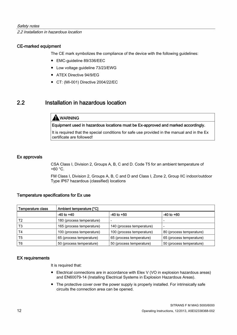
Temperature specifications for Ex use
Temperature class Ambient temperature [°C]
-40 to +40 -40 to +50 -40 to +60
T2 180 (process temperature) - -
T3 165 (process temperature) 140 (process temperature) -
T4 100 (process temperature) 100 (process temperature) 80 (process temperature)
T5 65 (process temperature) 65 (process temperature) 65 (process temperature)
T6 50 (process temperature) 50 (process temperature) 50 (process temperature)
EX requirements
It is required that:
● Electrical connections are in accordance with Elex V (VO in explosion hazardous areas)
and EN60079-14 (Installing Electrical Systems in Explosion Hazardous Areas).
● The protective cover over the power supply is properly installed. For intrinsically safe
circuits the connection area can be opened.

Safety notes
2.2 Installation in hazardous location
SITRANS F M MAG 5000/6000
Operating Instructions, 12/2013, A5E02338368-002 13
● Appropriate cable connectors are used for the output cicuits: intrinsically safe: blue, non-
intrinsically safe: black
● Sensor and transmitter are connected to the potential equalization. For intrinsically safe
output circuits potential equalization must be maintained along the entire connection path.
● Sensor insulation thickness is max. 100mm (only insulated sensors).
● EN50281-1-2 is considered for installation in areas with combustible dust.
● When protective earth (PE) is connected, no potential difference between the protective
earth (PE) and the potential equalization (PA) can exist, even during a fault condition.

Safety notes
2.2 Installation in hazardous location
SITRANS F M MAG 5000/6000
14 Operating Instructions, 12/2013, A5E02338368-002

SITRANS F M MAG 5000/6000
Operating Instructions, 12/2013, A5E02338368-002 15
3 Description 3
3.1 System components
A SITRANS F M MAG 5000/6000 flowmeter system includes:
● Transmitter (type SITRANS F M MAG 5000/6000)
● Sensor (types: SITRANS F MAG 1100/1100F/3100/3100 P/5100 W)
● Communication module (optional) (types: HART, PROFIBUS PA/DP, MODBUS RTU RS
485, Foundation Fieldbus H1, Devicenet)
● SENSORPROM memory unit
Communication solutions
The SITRANS F USM II range of add on modules, presently including HART, Foundation
Fieldbus. MODBUS RTU RS 485, PROFIBUS PA / DP and Devicenet, are all applicable with
the SITRANS F M MAG 6000 transmitter.
3.2 Operating principle
The transmitters are microprocessor-based with a built-in alphanumeric display in several
languages. The flow measuring principle is based on Faraday's law of electromagnetic
induction. Magnet coils mounted diametrically on the measuring pipe generate a pulsed
electromagnetic field. The liquid flowing through this electromagnetic field induces a voltage.
The transmitters evaluate the signals from the associated electromagnetic sensors, convert
the signals into appropriate standard signals such as 4 ... 20 mA, and also fulfil the task of a
power supply unit providing the magnet coils with a constant current.
The transmitter consists of a number of function blocks which convert the sensor voltage into
flow readings.
3.3 Applications
The pulsed DC-powered magnetic flowmeters are suitable for measuring the flow of almost
all electrically conductive liquids, pastes, and slurries with max. 40% solids.
The main applications can be found in the following sectors:
● Water and waste water
● Chemical and pharmaceutical industries
● Food & beverage industry
● Mining and cements industries

Description
3.4 Features
SITRANS F M MAG 5000/6000
16 Operating Instructions, 12/2013, A5E02338368-002
● Pulp and paper industry
● Steel industry
● Power generation; utility and chilled water industry
3.4 Features
Power supply
2 different types of power supply are available. A 12 ... 24 V AC/DC and a 115 ... 230 V AC
switch mode type.
Coil current module generates a pulsating magnetizing current that drives the coils in the
sensor. The current is permanently monitored and corrected. Errors or cable faults are
registered by the self-monitoring circuit.
Input circuit amplifies the flow-proportional signal from the electrodes. The input impedance
is extremely high: >1014 Ω which allows flow measurements on fluids with conductivities as
low as 5 µS/cm. Measuring errors due to cable capacitance are eliminated due to active
cable screening.
Digital signal processor converts the analog flow signal to a digital signal and suppresses
electrode noise through a digital filter. Inaccuracies in the transmitter as a result of long-term
drift and temperature drift are monitored and continuously compensated for via the self-
monitoring circuit. The analog to digital conversion takes place in an ultra low noise ASIC
with 23 bit signal resolution. This has eliminated the need for range switching. The dynamic
range of the transmitter is therefore unsurpassed with a turn down ratio of minimum 3000:1.
CAN communication
The transmitter operates internally via an internal CAN communication bus. Signals are
transferred through a signal conditioner to the display module and to/from internal/external
option modules and the dialog module.
Dialog module
The display unit consists of a 3-line display and a 6-key keypad. The display shows a flow
rate or a totalizer value as a primary reading.
Output module
The output module converts flow data to analog, digital and relay outputs. The outputs are
galvanically isolated and can be individually set to suit a particular application.

Description
3.5 MAG 5000/MAG 6000 versions
SITRANS F M MAG 5000/6000
Operating Instructions, 12/2013, A5E02338368-002 17
3.5 MAG 5000/MAG 6000 versions
The transmitters are designed in various versions and offer high performance and easy
installation, commissioning and maintenance.
Standard version
The standard version is an IP67 version for compact or remote installation. Its robust design
ensures a long lifetime if installed outdoors.
Blind version
This version carries all the normal MAG 5000/6000 features, except those associated with
the display and keypad.
Both current and digital outputs are available.
Factory setting of current output in unit is switched off when delivered.
CT version
The MAG 5000/6000 CT version is a custody transfer-approved transmitter.
It is approved according to:
● Cold water pattern approval (MAG 5000/6000 CT):
– OIML R 49
● Cold water pattern approval (MAG 6000 CT only):
– MI-001
● Hot water pattern approval (MAG 6000 CT only):
● Heat meter pattern approval (MAG 6000 CT only):
– OIML R 75
● Other media than water (MAG 6000 CT only):
– OIML R 117
* Energy metering
- PTB K7.2
SV version (MAG 6000 only)
This version is identical to the standard MAG 6000 transmitters except for the following
additional functions:
● Zero point adjustment
● Adjustable excitation frequency up to 44 Hz

Description
3.5 MAG 5000/MAG 6000 versions
SITRANS F M MAG 5000/6000
18 Operating Instructions, 12/2013, A5E02338368-002

SITRANS F M MAG 5000/6000
Operating Instructions, 12/2013, A5E02338368-002 19
4 Installing/Mounting 4
4.1 Introduction
● SITRANS F flowmeters are suitable for indoor and outdoor installations.
WARNING
Installation in hazardous location
Special requirements apply to the location and interconnection of sensor and
transmitter. See "Installation in hazardous area"
This chapter describes how to install the flowmeter in the compact version as well as in the
remote version.
The transmitter is delivered ready for mounting on the sensor. The transmitter is delivered
with a compression plate ready for mounting on the sensor. No further assembling is
necessary.
The transmitter can be installed either compact on the sensor or remote.
Figure 4-1 Compact installation
Figure 4-2 Remote installation

Installing/Mounting
4.2 Installation conditions
SITRANS F M MAG 5000/6000
20 Operating Instructions, 12/2013, A5E02338368-002
CAUTION
See Cable requirements (Page 72) before installing transmitter
4.2 Installation conditions
Reading and operating the flowmeter is possible under almost any installation conditions
because the display can be oriented in relation to the sensor. To ensure optimum flow
measurement, attention should be paid to the following:
Vibrations
Figure 4-3 Avoid strong vibrations

Installing/Mounting
4.2 Installation conditions
SITRANS F M MAG 5000/6000
Operating Instructions, 12/2013, A5E02338368-002 21
Compact installation
Medium temperature must be in accordance with the graphs showing max. ambient
temperature as a function of medium temperature.
Figure 4-4 Standard, blind and SV versions
Figure 4-5 CT version
Remote installation
Cable length and type (as described in Cable requirements (Page 72)) must be used.
For installation conditions for sensors, see respective sensor operating instructions.

Installing/Mounting
4.3 MAG 5000/6000 compact
SITRANS F M MAG 5000/6000
22 Operating Instructions, 12/2013, A5E02338368-002
4.3 MAG 5000/6000 compact
Install MAG 5000 / MAG 6000 compact version
1. Remove and discard terminal box lid of sensor.
2. Ensure SENSORPROM® memory unit is installed.
3. Fit M20 or ½" NPT cable glands for supply and output cables.
4. Unplug the two black plug assemblies for coil and electrode cables in terminal box.
5. Connect earth wire from connection board to bottom of terminal box.
6. Connect 2-pin connector and 3-pin connector as shown to their corresponding terminal
numbers on connection board as shown in Electrical connection (Page 36).
Note
System will not register flow if black plugs are not connected to connection board.
7. Fit supply and output cables through cable glands and connect to connection plate as
shown in Electrical connection (Page 36).

Installing/Mounting
4.3 MAG 5000/6000 compact
SITRANS F M MAG 5000/6000
Operating Instructions, 12/2013, A5E02338368-002 23
8. Mount connection plate in terminal box.
Note
Check that your connection board lines up with SENSORPROM® unit, if not, move
SENSORPROM® unit to the other side of terminal box.
SENSORPROM® memory unit connections will be established automatically when
connection plate is mounted in terminal box.
9. Tighten cable glands to obtain optimum sealing.
10. Mount transmitter on terminal box.
11. Transmitter is ready to be powered up.
NOTICE
Exposing transmitter to direct sunlight may increase operating temperature above its
specified limit, and decrease display visibility.
A sunshield is available as accessory.

Installing/Mounting
4.4 Remote installation
SITRANS F M MAG 5000/6000
24 Operating Instructions, 12/2013, A5E02338368-002
4.4 Remote installation
At sensor
1. Remove terminal box lid.
2. Remove SENSORPROM® unit from sensor terminal box and mount it in terminal box of
wall mounting unit.
3. Fit M20 or ½" NPT cable glands for cables.
Installing/Mounting
4.4 Remote installation
SITRANS F M MAG 5000/6000
Operating Instructions, 12/2013, A5E02338368-002 25
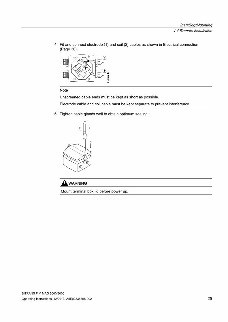
4. Fit and connect electrode (1) and coil (2) cables as shown in Electrical connection
(Page 36).
Note
Unscreened cable ends must be kept as short as possible.
Electrode cable and coil cable must be kept separate to prevent interference.
5. Tighten cable glands well to obtain optimum sealing.
WARNING
Mount terminal box lid before power up.

Installing/Mounting
4.4 Remote installation
SITRANS F M MAG 5000/6000
26 Operating Instructions, 12/2013, A5E02338368-002
Wall mounting
1. Mount bracket on a wall or on a horizontal or a vertical pipe using ordinary hose clips or
duct straps.
Figure 4-6 Wall mounting
Figure 4-7 Pipe mounting - vertical
Figure 4-8 Pipe mounting - horizontal
2. Ensure that correct SENSORPROM® memory unit is mounted in wall/pipe mounting unit.

Installing/Mounting
4.4 Remote installation
SITRANS F M MAG 5000/6000
Operating Instructions, 12/2013, A5E02338368-002 27
3. Fit M20 or ½" NPT cable glands for cables from bottom or sides of terminal box.
4. Mount earth wire in bottom of terminal box.
① Connect electrode cable
② Connect coil cable - keep separate from electrode cable
③ Connect power supply
④ Connect output cable
⑤ Connect PE (ground) wire
5. Mount connection plate in terminal box.
① Electrode cable
② Coil cable
③ Power supply
④ Output cable
6. Fit coil, electrode, supply and output cables through cable glands and connect to
connection plate as shown in Electrical connection (Page 36).
7. Fix connection plate with the two diagonally opposite screws.

Installing/Mounting
4.5 MAG 5000/6000 CT
SITRANS F M MAG 5000/6000
28 Operating Instructions, 12/2013, A5E02338368-002
8. Tighten cable glands to obtain optimum sealing.
CAUTION
When remote mounted, power supply PE wire must be connected to PE terminal ( ).
Coil cable shield must be connected to SHIELD terminal.
9. Mount transmitter on terminal box.
10. Transmitter is ready to be powered up.
NOTICE
Exposing the transmitter to direct sunlight may increase the operating temperature
above its specified limit, and decrease display visibility.
A sun shield is available as accessory.
4.5 MAG 5000/6000 CT
To ensure that the settings of this custody transfer-approved MAG 5000/6000 CT transmitter
are not changed, it is necessary to install a hardware key to lock the software functions and
to seal the device.
MAG 6000 CT is installed like a Standard MAG 6000 except for the final sealing.
Calibration sealing has been carried out at calibration.

Installing/Mounting
4.5 MAG 5000/6000 CT
SITRANS F M MAG 5000/6000
Operating Instructions, 12/2013, A5E02338368-002 29
4.5.1 Installing hardware key
Use hardware key on non-verified transmitter
1. Mount hardware key on transmitter connection plate during setting of primary operating
parameters such as Qmax., low-flow cut-off, units, approvals, etc. in connection with
commissioning or calibration. See setup menus in appendix menu diagrams.
2. Remove hardware key after setting up and calibrating unit.
This locks the menu structure and the selected settings.
Note
Hardware key function
Setting of primary operating parameters is blocked during normal operation.
When key is mounted, access to all menu items is gained. When key is removed, primary
settings are blocked in accordance with requirements in authorisation.
4.5.2 Seal device
Seal transmitter
CAUTION
Seal transmitter to prevent unauthorized access.

Installing/Mounting
4.5 MAG 5000/6000 CT
SITRANS F M MAG 5000/6000
30 Operating Instructions, 12/2013, A5E02338368-002
1. Seal connection plate to prevent access to SENSORPROM® memory unit as shown
below. 1 indicates sealing locations.
2. Drill through marked drilling holes in terminal box and transmitter/lid. Seal transmitter
externally as shown below.

Installing/Mounting
4.6 Turning transmitter/keypad
SITRANS F M MAG 5000/6000
Operating Instructions, 12/2013, A5E02338368-002 31
4.5.3 Installation conditions
4.5.3.1 MI-001
MAG 5000/6000 CT together with MAG 5100W (7ME652) are approved for Mi-001 under the
following installation conditions.
● DN 50 to 300 mm (2" to 12")
● Horizontal installation
● Compact or remote with max. 3 m cable
● Power supply 115/230 V AC
Other restrictions may apply (see certificate).
4.5.3.2 PTB K7.2
MAG 5000/6000 CT together with MAG 5100W (7ME652) are approved for PTB K7.2 under
the following installation conditions.
SITRANS F M MAG 5100 W with MAG 5000/6000CT
● DN 50 to 300 mm (2" to 12")
● Horizontal installation
● Compact or remote with max. 10 m (33 ft.) cable
Other restrictions may apply (see certificate 22.76/10.02)
**insert installation conditions as pasted
4.6 Turning transmitter/keypad
It is possible to alter the standard assembly, e.g. to turn transmitter or keypad.

Installing/Mounting
4.6 Turning transmitter/keypad
SITRANS F M MAG 5000/6000
32 Operating Instructions, 12/2013, A5E02338368-002
Transmitter
Figure 4-9 Transmitter can be mounted with its front in either direction indicated by the arrows
without turning terminal box
Figure 4-10 Terminal box can be rotated ±90° in order to optimize viewing angle of transmitter
display/keypad
1. Unscrew the four screws in bottom of terminal box.
2. Turn terminal box to required position.
3. Retighten screws firmly.

Installing/Mounting
4.6 Turning transmitter/keypad
SITRANS F M MAG 5000/6000
Operating Instructions, 12/2013, A5E02338368-002 33
Keypad
1. Remove outer frame using a screwdriver.
2. Loosen the four screws retaining keypad.
3. Withdraw keypad and turn it to required orientation.

Installing/Mounting
4.6 Turning transmitter/keypad
SITRANS F M MAG 5000/6000
34 Operating Instructions, 12/2013, A5E02338368-002
4. Tighten the four screws until a mechanical stop is felt in order to obtain IP67 enclosure.
5. Snaplock outer frame onto keypad (click).

SITRANS F M MAG 5000/6000
Operating Instructions, 12/2013, A5E02338368-002 35
5 Connecting 5
WARNING
Mains supply from building installation Class II
A switch or circuit breaker (Max. 15 A) must be installed in close proximity to the equipment
and within easy reach of the operator. It must be marked as the disconnecting device for
the equipment.
WARNING
Protective conductor terminal
The required cable is min. AGW16 or 1.5 Cu.
WARNING
Wire insulation
The insulation between the connected mains supply and 24 V AC/DC supply for the
flowmeter must at least be rated with double or reinforced insulation at mains voltage.
For field wiring installation: Ensure that the National Installation Code of the country in
which the flowmeters are installed is met.
Note
National installation code
Observe country specific installation directives for field wiring.

Connecting
5.1 Electrical connection
SITRANS F M MAG 5000/6000
36 Operating Instructions, 12/2013, A5E02338368-002
5.1 Electrical connection
Figure 5-1 Wiring diagram

Connecting
5.1 Electrical connection
SITRANS F M MAG 5000/6000
Operating Instructions, 12/2013, A5E02338368-002 37
Note
Terminals 81 and 84 are only to be connected if special electrode cable with double
screening is used, e.g. when empty pipe function or long cables are used.
Mains supply
Mains supply 115 ... 230 V AC from building installation Class II.
Note
For DC installations it is recommend to install an under voltage relay or protection circuit in
the application where there is a risk of low power supply below the specifications for more
than 10 minutes.
WARNING
Grounding
Connect mains protective earth wire to PE terminal in accordance with diagram (due to
class 1 power supply).
Mechanical counter
Connect a 1000 µF capacitor (capacitor+ to terminal 56 and capacitor- to terminal 58) if a
mechanical counter is connected to terminals 57 and 58 (active output).
Output cables
Use screened cables if long cables are used in noisy environments.
Digital output
If internal resistance of a load exceeds 10 kΩ, connect an external 10 kΩ load resistor in
parallel to this load.
WARNING
Intrinsically safe terminals
Always ensure that distance between cables/wires is minimum 50 mm in order to avoid that
wires/terminals of intrinsically safe circuits get into contact with wires of other cables.
Fasten cables/wires in a way that they cannot get into contact with each other, not even in
case of an error. Keep wire ends as short as possible.

Connecting
5.2 Electrical connection PTB K7.2
SITRANS F M MAG 5000/6000
38 Operating Instructions, 12/2013, A5E02338368-002
5.2 Electrical connection PTB K7.2
Additional Electrical connection for PTB K7.2 approved MAG5000/6000 with MAG5100W
(7ME652)
5.3 Connection of add-on modules
When the add-on module has been installed, the electrical connections are available on
terminal rows 91-97.
For more information
Refer to the relevant BUS communication Quick Start or Operating Instructions available at
the SITRANS F literature CD or on the internet, at : www.siemens.com/flowdocumentation
(www.siemens.com/flowdocumentation).

SITRANS F M MAG 5000/6000
Operating Instructions, 12/2013, A5E02338368-002 39
6 Commissioning 6
In this chapter it is described how to commission the device via the local user interface (LUI).
The display is described in details in section Local user interface (Page 40).
Furthermore, the following functions are described in details:
● Changing password (Page 42)
● Changing basic settings (Page 43)
● Changing operator menu setup (Page 45)
● Changing language (Page 46)
Detailed diagrams concerning the specific menu are shown in appendix menu diagrams.
For factory settings, see Factory settings.
6.1 MAG 5000/6000 Blind
Note
Does not have a display. All factory settings will be uploaded from the SENSORPROM® unit
after power-up.
For sensor dependent factory settings, see Appendix B.
Changing settings
If other settings are required, a standard transmitter with display and similar power supply
can be used.
1. Unscrew and remove MAG 5000/6000 Blind.
2. Mount standard MAG 5000/6000 transmitter.
3. Change required settings via display and keypad.
All changed data will be stored in SENSORPROM® memory unit.
4. Remove standard transmitter and remount Blind transmitter.
5. Fasten screws holding transmitter.
New settings stored in SENSORPROM® memory unit will be uploaded in blind transmitter.

Commissioning
6.2 Local user interface
SITRANS F M MAG 5000/6000
40 Operating Instructions, 12/2013, A5E02338368-002
6.2 Local user interface
S Sign field
P Primary field for numeric value flow rate, Totalizer 1 or Totalizer 2)
U Unit field
T Title line with individual information according to operator or setup menu selected.
ST Subtitle line which will either add information to the title line or keep individual information
independent of the title line.
F Alarm field. Two flashing triangles will appear in case of a fault condition.
M Mode field
L Lock field
Figure 6-1 Local User Interface
Mode field symbols
Communication mode
Language mode
Sensor characteristics
Service mode
Basic settings
Reset mode
Operator menu
Output
Operator-active
Product identity
External input
Operator-inactive

Commissioning
6.3 Menu structure
SITRANS F M MAG 5000/6000
Operating Instructions, 12/2013, A5E02338368-002 41
Lock field symbols
Ready for change
Access to submenu
Value locked
RESET MODE: Zero setting of totalizers and
initialization of setting
Keypad
The keypad is used to set the flowmeter. The keys function as follows:
TOP UP KEY
This key (when held for 2 sec.) is used to switch between
operator menu and setup menu. In transmitter setup menu, a
short press will cause a return to previous level.
FORWARD KEY
This key is used to step forward through the menus. It is the
only key normally used by the operator.
BACKWARD KEY
This key is used to step backwards through the menus.
CHANGE KEY
With this key settings or numerical values are changed.
SELECT KEY
With this key figures to be changed are selected.
LOCK/UNLOCK
KEY
This key enables the operator to change settings and it gives
access to submenus.
6.3 Menu structure
The menu is built up of two parts. An operator menu and a setup menu, see also overview
diagrams MAG 5000/6000 and MAG 5000/6000 CT.
Operator menu
The operator menu is for daily operation. It is customized in the operator menu setup. The
transmitter always starts up in operator menu No. 1. The forward and the backward keys
are used to step through the operator menus.
Setup menu
The setup menu is for commissioning and service only. Access to the setup menu is gained
by pressing the top up key for 2 seconds. The setup menu operates in two modes:
● View mode
● Setup mode
View mode is a read-only mode. The pre-selected settings can only be scanned.

Commissioning
6.4 Changing password
SITRANS F M MAG 5000/6000
42 Operating Instructions, 12/2013, A5E02338368-002
Setup mode is a read and write mode. The pre-selected settings can be scanned and
changed. Access to the setup mode is password-protected. The factory set password is
1000.
Access to a submenu in the setup menu is gained by pressing the lock key . Press the top
up key briefly to return to the previous menu. Press longer (2 sec.) to exit the setup menu
and return to operator menu No. 1.
6.4 Changing password
The setup menu is password-protected in order to ensure that only authorized personnel can
make any changes in transmitter settings.
Change password as follows:
1. Press top up key for 2 sec.
2. Enter password.
3. Use forward key or backward key to reach password menu.
4. Press lock/unlock key to unlock password.
5. Use select key and change key to change password.
6. Press lock/unlock key to confirm new password.
7. Press top up key two times to exit setup mode.
See change password diagram.
The factory-set password is 1000, but it can be changed to any value between 1000 and
9999.
Factory setting of password can be re-established as follows:
1. Switch off power supply.
2. While pressing top up key - switch on power supply.
3. Release top up key after 10 sec.

Commissioning
6.5 Changing basic settings
SITRANS F M MAG 5000/6000
Operating Instructions, 12/2013, A5E02338368-002 43
6.5 Changing basic settings
In the basic settings menu it is possible to set the following parameters:
Parameter Description
Main frequency Selection of main power supply frequency corresponding to the country in
which the flowmeter is installed (e.g. 60 Hz in America).
Flow direction Selection of correct flow direction in pipe.
Customer units Setting of user defined volume and time units.
Qmax Setting of measuring range, analog outputs and frequency output. Also
individual dimension-dependent setting of value, decimal point, unit and time.
Qmax 2 Setting of measuring range, analog outputs and frequency output. Also
individual dimension-dependent setting of value, decimal point, unit and time.
This menu is only visible if chosen as external digital input.
Totalizer Setting of unit and decimal point.
Low flow cut-off Setting of a percentage of selected Qmax. This filters noise in installation
reducing fluctuations in display and all outputs.
Empty pipe cut-off When set to "On" the alarm will indicate when sensor is running empty. All
readings, display and outputs, will indicate zero.
Velocity unit Setting of velocity unit per time unit
Error level Selecting error level at which flowmeter will detect an error.
Note
Totalizer 2 is not visible when batch is selected as digital output.
Note
Qmax 2 is visible only when chosen as digital input.
Change basic settings as follows:
1. Press top up key for 2 sec.
2. Enter password.
3. Use forward key to reach basic settings menu.
4. Press lock/unlock key to unlock settings.
5. Use forward key or backward key to reach relevant menu.
6. Press lock/unlock key to unlock settings.
7. Use select key and change key to change settings.
8. Press lock/unlock key to confirm new settings.

Commissioning
6.5 Changing basic settings
SITRANS F M MAG 5000/6000
44 Operating Instructions, 12/2013, A5E02338368-002
9. Repeat steps 5-8 to change other settings.
10. Press top up key two times to exit setup mode.
Decimal point can be positioned and units set individually for flow rate in totalizer 1 and
totalizer 2.

Commissioning
6.6 Changing operator menu setup
SITRANS F M MAG 5000/6000
Operating Instructions, 12/2013, A5E02338368-002 45
Changing decimal point position
1. Enter the respective totalizer menu.
2. Use select key to position cursor below decimal point.
3. Use change key to move decimal point to requested position.
Changing units
1. Use select key to position cursor below unit.
2. Press change key until requested unit is displayed.
6.6 Changing operator menu setup
In the operator menu the menus required for daily operation of the flowmeter are shown. It is
possible to hide and change some of the menus in the operator menu. This is done in the
operator menu setup menu, see operator menu setup diagram.
Customizing menus in operator menu
To customize the menus in the operator menu perform the following steps:
1. Press top up key for 2 sec.
2. Enter password.
3. Use forward key or backward key to reach operator menu.
Changing text in line 1
1. Press lock/unlock key to unlock setting.
2. Use change key to select desired text.
3. Press lock/unlock key to confirm selected text.
Note
If "Text" is selected in line 2, this line functions as a heading for the value shown in line 3.
Otherwise it shows the actual value of the reading selected.
Enabling two readings
1. Use forward key to reach requested menu.
2. Press lock/unlock key to unlock setting.
3. Use select key to move cursor to upper line.
4. Use change key to select requested reading.
5. Press lock/unlock key to confirm selection.

Commissioning
6.7 Changing language
SITRANS F M MAG 5000/6000
46 Operating Instructions, 12/2013, A5E02338368-002
6. Use select key to move cursor to line 3.
7. Use change key to select desired setting.
8. Press lock/unlock key to confirm new setting.
9. Repeat steps 1-8 for each requested menu.
Showing/hiding menus in operator menu
1. Use forward key to reach requested menu.
2. Press lock/unlock key to unlock setting.
3. Use select key to move cursor to / symbol.
4. Press change key to select visible ( ) or hidden ( ).
5. Press lock/unlock key to confirm new setting.
6.7 Changing language
It is possible to change language in transmitter. Default language is English, but it can be
changed to various other languages.
Change language as follows:
1. Press top up key for 2 sec.
2. Enter password.
3. Use forward key or backward key to reach language menu.
4. Press lock/unlock key to unlock language.
5. Use change key to select desired language.
6. Press lock/unlock key to confirm new language.
7. Press top up key two times to exit setup mode.

SITRANS F M MAG 5000/6000
Operating Instructions, 12/2013, A5E02338368-002 47
7 Functions 7
This chapter describes the various menus of the transmitter in details. The menu diagrams
are shown in appendix menu diagrams.
7.1 Output settings
Three outputs are available:
● Current output (range and time constant); terminals 31 and 32.
● Digital output (pulse, frequency, error, limit, or batch settings); terminals 56, 57, and 58.
● Relay output (error, limit, and batch settings); terminals 44, 45, and 46.
Current output
In the current output menu it is possible to select current output direction, range and time
constant, see also Current output menu diagram.
If current output "4-20 mA + Alarm" is selected, then alarm level and alarm differentiation
may also be defined.
"Alarm level" defines if an alarm should be above 21 mA "High" or below 3.6 mA "Low".
"Alarm diff." defines whether or not the alarm should vary according to selected error level.
Error level "Fatal". "Permanent" or "Warning" is selected in "Basic settings".
If Alarm differentiation is set to "Yes", depending on the Alarm level setting, the current
output will show:
Alarm level Output / Error level
Fatal Permanent Warning
Low 1.3 mA 2 mA 3 mA
High 23 mA 22 mA 21.5 mA
If Alarm differentiation is set to "No", depending on the Alarm level setting, the current output
will show:
Alarm level Output
Low 3.5 mA
High 22.6 mA
For setting of error level, see Error level menu diagram.
If current output is not used, it must be set to "Off".

Functions
7.1 Output settings
SITRANS F M MAG 5000/6000
48 Operating Instructions, 12/2013, A5E02338368-002
Digital output
Digital output can be used to configure various settings:
● Pulse (volume/pulse, pulse output, pulse width, pulse polarity, and time constant), see
pulse menu diagram.
● Frequency (frequency output, max frequency, and time constant), see frequency menu
diagram.
● Error settings (level and number), see error level menu diagram and error number menu
diagram.
● Limit settings (number of setpoints, setpoint settings, and hysteresis), see direction/limit
menu diagram.
● Batch settings (quantity, time and counter settings, and time constant), see batch menu
diagram.
Note
Batch settings
Only MAG 6000.
Not available in MAG 5000, MAG 5000 CT and MAG 6000 CT.
Note
When relay is set to batch function, pulse/frequency is not available on digital output.
Relay outputs
Relay output can be used to configure various settings:
● Error settings (level and number), see error level menu diagram and error number menu
diagram.
● Limit settings (number of setpoints, setpoint settings, and hysteresis), see direction/limit
menu diagram.
● Batch settings (quantity, time and counter settings, and time constant), see batch menu
diagram.
● Cleaning (cycle time), see cleaning menu diagram.
Note
Batch settings
Only MAG 6000.
Not available in MAG 5000, MAG 5000 CT and MAG 6000 CT.
Note
Cleaning
If a cleaning unit is installed together with transmitter, relay output must always be used
to operate this unit. It cannot be used for other purposes.

Functions
7.2 External input
SITRANS F M MAG 5000/6000
Operating Instructions, 12/2013, A5E02338368-002 49
7.2 External input
By applying 11 … 30 V DC to terminals 77 and 78, it is possible to perform:
● Batch control (start, stop, hold/continue)
● Reset totalizer
● Force/freeze output
● Qmax 2 (night)
See external input menu diagram.
Note
Batch settings
Only MAG 6000.
Not available in MAG 5000, MAG 5000 CT and MAG 6000 CT.
Note
Manual cleaning
If the digital input is used for manual cleaning, the relay output also automatically changes to
"cleaning".
7.3 Sensor characteristics
The sensor characteristics menu shows:
● If a SENSORPROM® is installed or not.
● Suppress error P 40 (SENSORPROM® not installed)
● Sensor size.
● Calibration factor.
● Correction factor.
● Excitation.
See also sensor characteristics menu diagram.
7.4 Reset mode
The reset mode is used for resetting totalizers/counters or for restoring MAG 5000/6000 to
its factory settings.

Functions
7.4 Reset mode
SITRANS F M MAG 5000/6000
50 Operating Instructions, 12/2013, A5E02338368-002
Resetting
1. Press top up key for 2 sec.
2. Enter password.
3. Use forward key or backward key to reach reset mode menu.
4. Press lock/unlock key to enter reset menu.
5. Press forward key to reach totalizer/counter to be reset or default setting menu.
6. Press lock/unlock key to start resetting.
If restoring of factory settings is required:
1. Press lock/unlock key again to confirm destruction of customized settings.
See also reset menu diagram.
Zero point adjustment (MAG 6000 SV only)
Auto adjustment
Before auto zero point adjustment is carried out ensure that valves to and from flowmeter are
completely closed and that flow velocity in sensor is zero.
1. Press top up key for 2 sec.
2. Enter password.
3. Use forward key or backward key to reach reset mode menu.
4. Press lock/unlock key to enter reset menu.
5. Press forward key to reach zero adjust menu.
6. Press lock/unlock key to enter the menu.
7. Use change key to select "auto".
8. Press forward key to view actual offset (lower line in display). Value will be zero after
adjustment has been performed.
9. Press lock/unlock key to start adjustment.
Manual adjustment.
1. Press top up key for 2 sec.
2. Enter password.
3. Use forward key or backward key to reach reset mode menu.
4. Press lock/unlock key to enter reset menu.
5. Press forward key to reach zero adjust menu.
6. Press lock/unlock key to enter the menu.
7. Use change key to select "manual".
Functions
7.5 Service mode
SITRANS F M MAG 5000/6000
Operating Instructions, 12/2013, A5E02338368-002 51
8. Press forward key and then select key and change key to key in offset value.
9. Press lock/unlock key to start adjustment.
Zero point can be adjusted manually in range -1.000 ... +1.000 m3/s. If value outside this
range is keyed in, zero point adjustment will not be implemented.
See also reset mode menu diagram (MAG 6000 SV).
7.5 Service mode
All outputs of the transmitter can be forced-controlled in the service mode menu, see also
service mode menu diagram.
Here it is possible to check whether e.g. the current output is functioning.
Error pending and status log lists are also accessible from this menu and the operating time
(in days) can be read.
The forced control is cut off and all previous settings are reinitialized the moment the service
mode is left by pressing top up key .
7.6 MAG 5000 CT and MAG 6000 CT settings
Internal totallizers
Depending on the type of approval it is possible to reset the internal totalizers. The type of
approval is selected in the reset menu with the hardware key mounted. It is possible to
choose between:
● Hot/cold water
● Other liquids
Resetting of totalizers by electrical input is not possible.
Hot/cold water
● Totalizer 1 is allocated to forward flow (cannot be reset)
● Totalizer 2 is allocated to reverse flow (cannot be reset)
Other liquids
Both totalizer 1 and totalizer 2 are allocated to measure the net flow, i.e. any reverse flow will
make the totalizers count backwards.
● Totalizer 1 cannot be reset.
● Totalizer 2 can be reset if the flow velocity in the meter pipe is <0.25 m/s. When the
totalizer is reset, the pulse output register will also be reset.

Functions
7.7 MAG 6000 SV
SITRANS F M MAG 5000/6000
52 Operating Instructions, 12/2013, A5E02338368-002
Output
● When choosing hot water, changing the output settings is not allowed and the output
setting menus are not shown in display.
● When choosing cold water or other liquids, all output settings can be changed.
7.7 MAG 6000 SV
Excitation frequency
The MAG 6000 SV excitation frequency can be changed in sensor characteristics menu to
one of the following frequencies:
● 1 9/16 Hz
● 3 1/8 Hz
● 6 ¼ Hz
● 12½ Hz
● 25 Hz
● 44 Hz
Note
Calibration has been made with the frequency stored in SENSORPROM® memory unit. A
change in excitation frequency is not recommended and will always mean decreased
measuring accuracy. In some instances, however, it may be necessary to change
frequency due to pulsating flow from piston pumps or other resonance frequencies from
surroundings.
It is highly recommended to carry out a External input (Page 49) after changing the excitation
frequency as the offset is affected by the frequency selected. When this is done, the
decrease in measuring accuracy can be kept below 1% o.r.
A too high frequency for the sensor used will cause a coil current alarm indication.

SITRANS F M MAG 5000/6000
Operating Instructions, 12/2013, A5E02338368-002 53
8 Alarm, error, and system messages 8
8.1 Diagnostics
Error system
Transmitter system is equipped with an error and status log system with 4 groups of
information.
(I) Information - system will continue to measure as normal, relay and current outputs will not
be affected.
(W) Warning - system will continue to measure, but an event that may cause a system
malfunction and require operator attention has occurred. The cause of the error may
disappear on its own.
(P) Permanent error - may cause malfunction in the application and operator attention is
required.
(F) Fatal error - is essential for the operation of the flowmeter. Immediate operator attention
is required.
Two menus are available in service and operator menus for registration of information and
errors.
● Error pending
● Status log
Note
Registration of errors in different modes
In setup mode (local dialog) errors are entered only to Error pending list and not to
Error log list, and not registered on physical outputs (current or relay).
In service mode errors are entered to both Error pending and Error log lists, but not
registered on physical outputs (current or relay).
Note
Power-off
Both error pending and status logs are reset at power-off.
Error pending
The first 9 pending errors are stored in the error pending list. When the error is corrected, it
is removed from the error pending list.
The acceptance level for "error pending" can be individually configured to a particular
application.
The acceptance level is set in the basic settings menu (Page 43).

Alarm, error, and system messages
8.1 Diagnostics
SITRANS F M MAG 5000/6000
54 Operating Instructions, 12/2013, A5E02338368-002
Acceptance levels
The following three acceptance levels are selectable.
● Fatal error: Only fatal errors are registered as errors
● Permanent error: Permanent and fatal errors are registered as errors
● Warning (Default value): Warnings, permanent and fatal errors are registered as errors
Error information is displayed in title and subtitle lines, see display layout (Page 40). Title line
will show time since occurrence of error in days, hours and minutes. Subtitle line will flash
between an error text and a remedy text. Error text will indicate type of error (I, W, P or F),
error number, and error text. Remedy text will inform operator of action to take to remove
error.
Status log
The latest 9 errors are stored in the status log. Errors are stored in the status log for 180
days, even if they are corrected.
Alarm field
The alarm field on the display will always flash when an error is pending.
Error output
The digital and relay output can be activated individually error by error (error level). The relay
output is default selected to error level. An output can also be selected to activate on a single
error number.
The alarm field, error output and error pending always operate together.
Operator menu
Error pending and status log are as default enabled ( ) in the operator menu.

Alarm, error, and system messages
8.2 List of error numbers
SITRANS F M MAG 5000/6000
Operating Instructions, 12/2013, A5E02338368-002 55
8.2 List of error numbers
Error
No.
Error text
Remedy text
Comment Output
status
Input
status
1 I1 - Power on
OK
Device powered on
Active
Active
2 I2 - Add-on module
Applied
A new module has been applied to the system
Active
Active
3 I3 - Add-on module
Install
An add-on module is defect or has been removed.
This can be an internal add-on module
Active
Active
4 I4 - Param. corrected
OK
A less vital parameter in the transmitter has been
replaced by its default value
Active
Active
20 W20 - Totalizer 1
Reset manually
During initialisation the check of the saved totalizer
value has failed. It is not possible to rely on the
saved totalizer value anymore. The totalizer value
must be reset manually in order to rely on future
readings
Active
Active
20 W20 - Totalizer 2
Reset manually
During initialisation the check of the saved totalizer
value has failed. It is not possible to rely on the
saved totalizer value anymore. The totalizer value
must be reset manually in order to rely on future
readings
Active
Active
21 W21 - Pulse overflow
Adj. pulse settings
Actual flow is too big compared with pulse width and
volume/pulse
Reduced pulse
width
Active
22 W22 - Batch timeout
Check installation
Duration of batching has exceeded a predefined
maximum time
Batch output
on zero
Active
23 W23 - Batch overrun
Check installation
Batch volume has exceeded a predefined maximum
overrun volume
Batch output
on zero
Active
24 W24 - Batch neg. flow
Check flow direction
Negative flow direction during batch
Active
Active
30 W30 - Overflow
Adj. Qmax
Flow is above Qmax settings
Max. 120 %
Active
31 W31 - Empty pipe
Pipe is empty
Zero
Active
40 P40 - SENSORPROM®
Insert/change
SENSORPROM® unit not installed
Active
Active
41 P41 - Parameter range
Switch off and on
A parameter is out of range. The parameter could
not be replaced by its default value. The error will
disappear at the next power-on
Active
Active

Alarm, error, and system messages
8.2 List of error numbers
SITRANS F M MAG 5000/6000
56 Operating Instructions, 12/2013, A5E02338368-002
Error
No.
Error text
Remedy text
Comment Output
status
Input
status
42 P42 - Current output
Check cables
Current loop is disconnected or the loop resistance
is too big
Active
Active
43 P43 - Internal error
Switch off and on
Too many errors occurred at the same time.
Some errors are not detected correctly
Active
Active
44 P44 - CT SENSORPROM®
SENSORPROM® unit has been used as CT version
Active
Active
60 F60 - CAN comm. error
Transmitter/AOM
CAN bus communication error. An add-on module,
the display module or the transmitter is defective
Zero
Inactiv
e
61 F60 - SENSORPROM® error
Replace
It is not possible to rely on the data in
SENSORPROM® unit anymore
Active
Active
62 F62 - SENSORPROM® ID
Replace
The SENSORPROM® unit ID does not comply with
the product ID.
The SENSORPROM® unit is from another type of
product SITRANS F C, SITRANS F US etc.
Zero
Inactiv
e
63 F63 - SENSORPROM®
Replace
It is not possible to read from the SENSORPROM®
unit anymore
Active
Active
70 F70 - Coil current
Check cables
Coil excitation has failed
Active
Active
71 F71 - Internal error
Replace transmitter
Internal convertion error in ASIC
Active
Active

SITRANS F M MAG 5000/6000
Operating Instructions, 12/2013, A5E02338368-002 57
9 Service and maintenance 9
The device is maintenance-free, however, a periodic inspection according pertinent
directives and regulations must be carried out.
An inspection can include check of:
● Ambient conditions
● Seal integrity of the process connections, cable entries, and cover screws
● Reliability of power supply, lightning protection, and grounds
Under ideal conditions the flowmeter will operate continuously with no manual adjustment or
intervention required.
The SITRANS F M Verificator is an external tool developed for verifying the MAG 5000/6000
system, installation, and application. It is a highly advanced instrument, which carries out the
complex verification of the entire flowmeter system according to unique SIEMENS patented
principles. The verification test is automated and the instrument easy to use, so no human
error or influence will affect the verification.
9.1 Transmitter check list
If unstable/wrong measurements occur, it is often due to insufficient/wrong earthing or
potential equalization. If earthing connection is OK, check transmitter as described below,
and sensor as described in sensor check lists (see the respective operating instructions).
The easiest way to check the transmitter in a SITRANS F M installation is to replace the
transmitter with another MAG 5000/6000 with a similar power supply.
As all settings are stored in and downloaded from the SENSORPROM®, replacement is
easily done and no extra settings need to be made.
Check transmitter
If no replacement transmitter is available, check transmitter according to the following check
table.
Power on transmitter
0 Display light on? Yes ⇒ 1
No ⇒ 2
1 Flashing error triangles? Yes ⇒ Check error table
No ⇒ 1.2
1.2 Output and display readings OK? Yes ⇒ 1.2.1
No ⇒ 1.2.2

Service and maintenance
9.2 Technical support
SITRANS F M MAG 5000/6000
58 Operating Instructions, 12/2013, A5E02338368-002
Power on transmitter
1.2.1 Transmitter OK Check application
Check installation/sensor/earthing
connection etc.
1.2.2 Check cables/conndections
Check connection board
Check pins in transmitter multiplug
OK ⇒ 1.2.1
Not OK ⇒ correct fault
2 Check cables/conndections
Check connection board
Check pins in transmitter multiplug
OK ⇒ 2.1
Not OK ⇒ Correct fault
2.1 Output readings OK? Yes ⇒ 2.1.1
No ⇒ 2.1.2.
2.1.1 Dispaly defective Replace display
2.1.2 Transmitter defective Replace transmitter
Note
Sensor check list
Check list for sensors are included in the respective sensor operating instructions.
9.2 Technical support
NOTICE
Repair and service must be carried out by approved Siemens Flow Instruments personnel
only.
Note
Siemens Flow Instrument defines sensors as non-repairable products.
Technical Support
If you have any technical questions about the device described in these Operating
Instructions and do not find the right answers, you can contact Technical Support:
● Via the Internet using the Support Request:
Support request (http://www.siemens.com/automation/support-request)
● Phone: +49 (0) 180 5050 222
Further information about our technical support is available in the Internet at
Technical support (http://support.automation.siemens.com/WW/view/en/16604318)

Service and maintenance
9.3 Return procedures
SITRANS F M MAG 5000/6000
Operating Instructions, 12/2013, A5E02338368-002 59
Service & Support on the Internet
In addition to our documentation, we offer a comprehensive knowledge base online on the
Internet at:
Service and support (http://www.siemens.com/automation/service&support)
There you will find:
● The latest product information, FAQs, downloads, tips and tricks.
● Our newsletter, providing you with the latest information about your products.
● A Knowledge Manager to find the right documents for you.
● Our bulletin board, where users and specialists share their knowledge worldwide.
● You can find your local contact partner for Industry Automation and Drives Technologies
in our partner database.
● Information about field service, repairs, spare parts and lots more under "Services."
Additional Support
Please contact your local Siemens representative and offices if you have additional
questions about the device
Find your contact partner at:
Local contact person (http://www.automation.siemens.com/partner)
9.3 Return procedures
Enclose the delivery note, the cover note for return delivery together with the declaration of
decontamination form on the outside of the package in a well-fastened clear document
pouch.

Service and maintenance
9.4 Recalibration
SITRANS F M MAG 5000/6000
60 Operating Instructions, 12/2013, A5E02338368-002
Required forms
● Delivery Note
● Cover Note for Return Delivery with the following information
Cover note
(http://cache.automation.siemens.com/dnl/zY/zY0OTg1AAAA_16604370_TxtObj/Begleits
chein_RW_AD.pdf)
– product (ordering number)
– number of devices or spare parts returned
– reason for the return
● Declaration of Decontamination
Decontamination declaration
(http://pia.khe.siemens.com/efiles/feldg/files/Service/declaration_of_decontamination_en.
pdf)
With this declaration you certify that the returned products/spare parts have been carefully cleaned and are free from any residues.
If the device has been operated together with toxic, caustic, flammable or water-
damaging products, clean the device before return by rinsing or neutralizing. Ensure that
all cavities are free from dangerous substances. Then, double-check the device to ensure
the cleaning is completed.
We will not service a device or spare part unless the declaration of decontamination
confirms proper decontamination of the device or spare part. Shipments without a
declaration of decontamination will be cleaned professionally at your expense before
further proceeding.
You can find the forms on the Internet and on the CD delivered with the device.
9.4 Recalibration
Siemens A/S Flow Instruments offers to recalibrate the sensor. The following calibrations are
offered as standard:
● Standard matched pair calibration
Note
For recalibration the SENSORPROM® memory unit must always be returned with the
sensor.

SITRANS F M MAG 5000/6000
Operating Instructions, 12/2013, A5E02338368-002 61
10 Troubleshooting/FAQs 10
Symptom Output
signals
Error
code
Cause Remedy
Empty display Minimum 1. No power supply Power supply
Check MAG 5000/6000 for bended
pins on the connector
2. MAG 5000/6000 defective Replace MAG 5000/6000
No flow signal Minimum 1. Current output disabled Turn on current output
2. Digital output disabled Turn on digital output
3. Reverse flow direction Change direction
F70 Incorrect or no coil current Check cables/connections
W31 Measuring pipe empty Ensure that the measuring pipe is full
F60 Internal error Replace MAG 5000/6000
Undefined P42 1. No load on current output Check cables/connections
2. MAG 5000/6000 defective Replace MAG 5000/6000
P41 Initializing error Switch off MAG 5000/6000, wait 5
sec. and switch on again
Indicates flow with no
flow in pipe
Undefined Measuring pipe empty Select empty pipe cut-off
Empty pipe cut-off is OFF Ensure that the measuring pipe is full
Electrode connection
missing/electrode cable is
insufficiently screened
Ensure that electrode cable is
connected and sufficiently screened
Unstable flow signal Unstable 1. Pulsating flow Increase time constant
2. Conductivity of medium too
low
Use special electrode cable
3. Electrical noise potential
between medium and sensor
Ensure sufficient potential
equalization
4. Air bubbles in medium Ensure medium does not contain air
bubbles
5. High concentration of
particles or fibres
Increase time constant
Measuring error Undefined Incorrect installation Check installation
P40 No SENSORPROM® unit Install SENSORPROM® unit
P44 CT SENSORPROM® unit Replace SENSORPROM® unit or
reset SENSORPROM® unit with MAG
CT transmitter
F61 Defective SENSORPROM®
unit
Replace SENSORPROM® unit
F62 Wrong type of
SENSORPROM® unit
Replace SENSORPROM® unit

Troubleshooting/FAQs
SITRANS F M MAG 5000/6000
62 Operating Instructions, 12/2013, A5E02338368-002
Symptom Output
signals
Error
code
Cause Remedy
F63 Defective SENSORPROM®
unit
Replace SENSORPROM® unit
F71 Loss of internal data Replace MAG 5000/6000
Maximum W30 Flow exceeds 100% of Qmax. Check Qmax (Basic Settings)
W21 Pulse overflow
Volume/pulse too small
Change volume/pulse
Pulse width too large Change pulse width
Measuring approx.
50%
Missing one electrode
connection
Check cables
Loss of totalizer data OK W20 Initializing error Reset totalizer manually
##### Signs in
display
OK Totalizer roll over Reset totalizer or increase totalizer
unit

SITRANS F M MAG 5000/6000
Operating Instructions, 12/2013, A5E02338368-002 63
11 Technical data 11
11.1 Technical specifications
Mode of operation and design Measuring principle Electromagnetic with pulsed constant field
Empty pipe Detection of empty pipe (special cable
required in remote mounted installation)
Excitation frequency Depends on sensor size
Electrode input impedance > 1 x 10¹⁴ Ω
Input Digital input 11 ... 30 V DC, Ri = 4.4 KΩ
Activation time 50 ms
Current IDC 11 V = 2.5 mA, IDC 30 V = 7 mA
Output Current output
Signal range 0 ... 20 mA or 4 ... 20 mA, Alarm
Load < 800 Ω
Time constant 0.1 … 30 s, adjustable (for batch: fixed at 0.1
s)
Digital output
Frequency 0 ... 10 kHz, 50% duty cycle
(uni/bidirectional)
Pulse (active) DC 24 V, 30 mA, 1 kΩ ≤ Ri ≤10 kΩ, short-
circuit protected (power supplied from
flowmeter)
Pulse (passive) DC 3 … 30 V, max. 110 mA, 200 Ω ≤ Ri ≤10
kΩ (powered from connected equipment)
Time constant 0.1 … 30 s, adjustable (for batch: fixed at 0.1
s)
Relay output
Time constant Changeover relay, same as current output
Load 42 V AC/2 A, 24 V DC/1 A
Low flow cut off 0 ... 9.9% of maximum flow
Galvanic isolation All inputs and outputs are galvanically isolated
Max. measuring error
(incl. sensor and zero point)
MAG 5000 0.4% ± 1 mm/s (for v > 0.1 m/s)

Technical data
11.1 Technical specifications
SITRANS F M MAG 5000/6000
64 Operating Instructions, 12/2013, A5E02338368-002
MAG 6000 0.2% ± 1 mm/s (for v > 0.1 m/s)
Functions Flow rate, 2 totalizers, low-flow cut-off, empty pipe cut-off, flow direction, error
system, operating time, uni/bidirectional flow, limit switches, pulse output, control for
cleaning and batch
Rated operation conditions Ambient temperature
Operation Standard IP67, 19", blind and SV versions:
-20 ... +60 °C (-4 ... +140 °F)
CT version:
-20 ... +50 °C (-4 ... +122 °F)
Storage -40 ... +70 °C (-40 ... +158 °F)
Mechanical load 18 ... 1000 Hz, 3.17 G rms, sinusoidal in all directions to IEC 68-2-36
Degree of protection IP67/NEMA 4X/6 to IEC 529 and DIN 40050 (1 mH2O 30 min.)
EMC performance EN 61326-1 (industrial environments)
EN 61326-2-5
Display and keypad Totalizer Two eight-digit counters for forward, net or
reverse flow
Display Background illumination with alphanumeric
text, 3 x 20 characters to indicate flow rate,
totalized values, settings and faults;
Reverse flow indicated by negative sign
Time constant Time constant as current output time constant
Design Enclosure material Fiber glass reinforced polyamide;
optional (IP67 only): AISI 316 stainless steel
Dimensions See dimensional drawings
Weight 0.75 kg (2 lb)
Power supply 115 ... 230 V AC +10% -15%, 50 ... 60 Hz, Fuse: 500 mA T
11 ... 30 V DC or 11 ... 24 V AC; Fuse 2 A T
Power consumption 115 ... 230 V AC: 17 VA
24 V AC: 9 VA, IN = 380 mA, IST = 8 A (30 ms)
12 V DC: 11 W, IN = 920 mA, IST = 4 A (250 ms)
Certificates and approvals CE, C-UL US general purpose, C-tick, CSA/FM Class 1, div 2
Custody transfer approval (MAG
5000/6000 CT)
Cold water pattern approval: PTB OIML R 49,
MI-001
Hot water pattern approval: DANAK OIML R
75 (MAG 6000 CT)
Other media than water (milk, beer etc.)
pattern approval: DANAK OIML R 117 (MAG
6000 CT) Energy metering : PTB K7.2
Communication MAG 5000 Without communication or HART as option
MAG 6000 Prepared for client mounted add-on modules:
HART, MODBUS RTU/RS485,
FOUNDATION Fieldbus H1, DeviceNet,
PROFIBUS PA, PROFIBUS DP as add-on
modules
MAG 5000 CT / MAG 6000 CT No communication modules approved

Technical data
11.1 Technical specifications
SITRANS F M MAG 5000/6000
Operating Instructions, 12/2013, A5E02338368-002 65
Transmitter IP67/NEMA 4X/6 compact polyamide
Weight: MAG 5000/6000: 0.75 kg (1.65 lbs)
Transmitter IP67/NEMA 4X/6 wall-mounted polyamide
Weight(transmitter and wall mounting bracket): 1.65 kg (3.64 lbs)

Technical data
11.2 Accuracy
SITRANS F M MAG 5000/6000
66 Operating Instructions, 12/2013, A5E02338368-002
11.2 Accuracy
For accuracy reference conditions, please see below.
Figure 11-1 MAG 5000 with MAG 1100, MAG 1100 F, MAG 5100 W, MAG 3100 and MAG 3100 P and MAG 6000 with
MAG 1100 (PFA), MAG 1100 F (PFA)

Technical data
11.2 Accuracy
SITRANS F M MAG 5000/6000
Operating Instructions, 12/2013, A5E02338368-002 67
Figure 11-2 MAG 6000 with MAG 1100 (not PFA), MAG 1100 F (not PFA), MAG 5100 W, MAG 3100 and MAG 3100 P
Reference conditions
(ISO 9104 and DIN/EN 29104)
A calibration certificate is shipped with every sensor and calibration data are stored in
SENSORPROM memory unit.
Medium temperature 20°C ± 5°C (68°F ± 9°C)
Ambient temperature 20°C ± 5°C (68°F ± 9°C)
Supply voltage Un ± 1%
Warming-up time 30 minutes
Incorporation in conductive pipe section
Inlet section
Outlet section
10 x DN (DN ≤ 1200/48")
5 x DN (DN > 1200/48")
5 x DN (DN ≤ 1200/48")
3 x DN (DN > 1200/48")
Flow conditions Developed flow profile
Reference conditions for sensor calibration

Technical data
11.3 Output characteristics
SITRANS F M MAG 5000/6000
68 Operating Instructions, 12/2013, A5E02338368-002
Current output As pulse output ± (0.1% of actual flow + 0.05% FSO)
Effect of ambient temperature
Display/frequency/pulse output
Current output
< ± 0.003% / °C act.
< ± 0.005% / °C act.
Effect of supply voltage < 0.005% of measuring value on 1% change
Repeatability ± 0.1% of actual flow for V ≥ 0.5 m/s (1.5 ft/s) and
conductivity ≥ 10 μS/cm
Additions in the event of deviations from reference conditions
11.3 Output characteristics
Current output
Output characteristics Bidirectional mode Unidirectional mode
0...20 mA
4...20 mA
Frequency output
Bidirectional mode Unidirectional mode
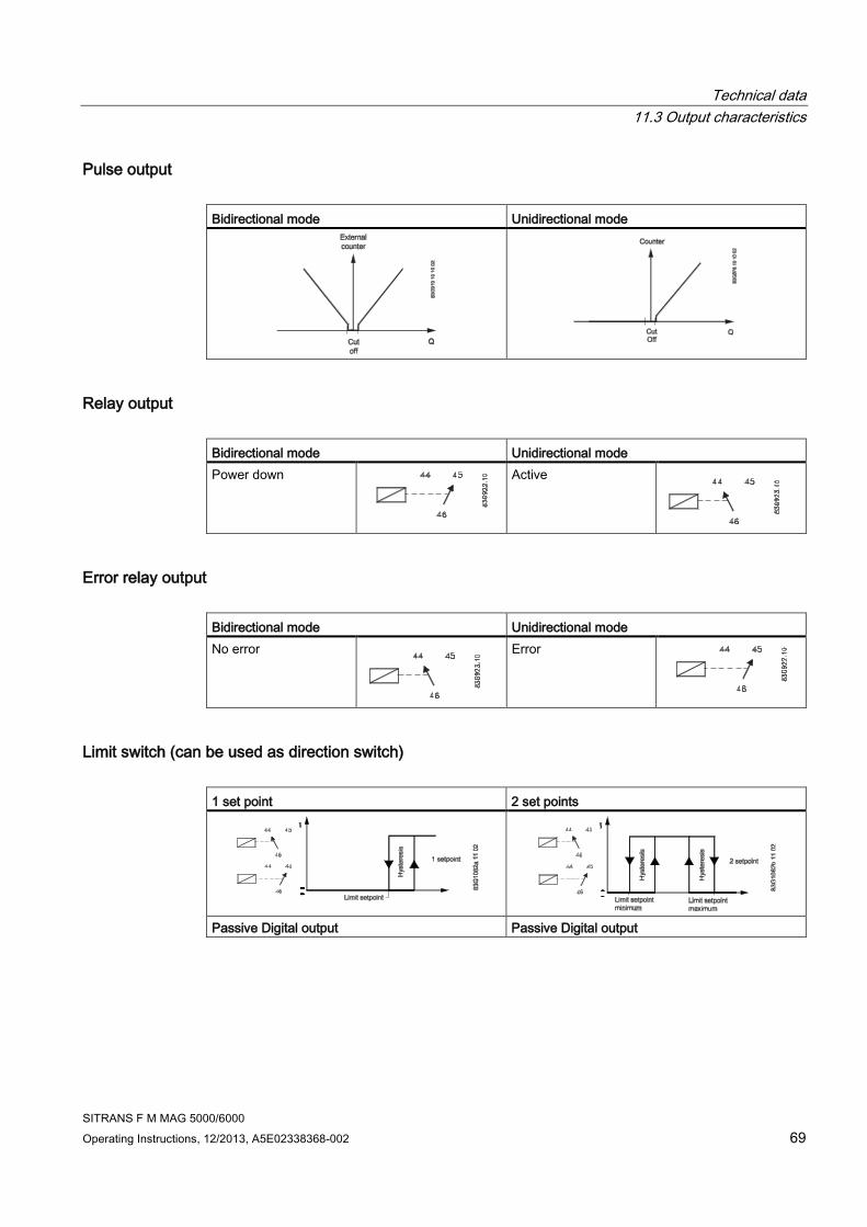
Technical data
11.3 Output characteristics
SITRANS F M MAG 5000/6000
Operating Instructions, 12/2013, A5E02338368-002 69
Pulse output
Bidirectional mode Unidirectional mode
Relay output
Bidirectional mode Unidirectional mode
Power down
Active
Error relay output
Bidirectional mode Unidirectional mode
No error
Error
Limit switch (can be used as direction switch)
1 set point 2 set points
Passive Digital output Passive Digital output

Technical data
11.3 Output characteristics
SITRANS F M MAG 5000/6000
70 Operating Instructions, 12/2013, A5E02338368-002
1 set point 2 set points
Note
Active digital output is not avaiable with MAG 6000 I.
Batch on digital output
Unidirectional mode (forward flow only)
Totalizer lap

Technical data
11.4 Cable data
SITRANS F M MAG 5000/6000
Operating Instructions, 12/2013, A5E02338368-002 71
Batch on relay output
Unidirectional mode (forward flow only)
Hold
Batch
11.4 Cable data
Description
Cable for standard electrode or coil
Electrode cable, double shielded
Cable kit with standard coil cable and electrode cable double
shielded (also available as low noise cable for MAG 1100
sensor )
Technical data
Standard electrode
cable
(electrode/coil)
Special cable
(electrode)
Basic data No. of conductors 3 3
Sqr. area 1.5 mm2 0.25 mm2
Screen Yes Double
Color code Brown, blue, black Brown, blue, black
Outside color Grey Grey
Ext. diameter 7.8 mm 8.1 mm
Conductor Flexible CU Flexible CU
Isolation material PVC PVC
Ambient temperature Flexible installation -5 ... +70°C
(23 ... 158°F)
-5 ... +70°C
(23 ... 158°F)
Non-flexible installtaion -30 ... +70°C
(-22 ... 158°F)
-30 ... +70°C
(-22 ... 158°F)
Cable parameter Capacity 161.50 pF/m N/A
Inductance 0.583 μH/m N/A
L/R 43.83 þH/Ω N/A

Technical data
11.5 Cable requirements
SITRANS F M MAG 5000/6000
72 Operating Instructions, 12/2013, A5E02338368-002
11.5 Cable requirements
Coil
cable
Electrode
cable
Basic data No. of conductors 2 3
Min. sqr. area 0.5 mm2 0.2 mm2
Screen Yes Yes
Max. capacitance N/A 350 pF/m
Max. cable loop resistance Media temperature:
< 100 °C 40 Ω N/A
> 200 °C 6 Ω N/A
Cable glands on sensor M20x1.5 gland - Cable ø 5 ... 13 mm (0.20 ... 0.51 inches)
½ NPT gland - cable ø 5 ... 9 mm (0.20 ... 0.35 inches)
WARNING
Cable glands
For Ex zone 1 installations only certified cable glands with protection type "e" can be used
for the power supply and the coil cable. The cable glands must be approved for the actual
temperature and cable dimension.

SITRANS F M MAG 5000/6000
Operating Instructions, 12/2013, A5E02338368-002 73
12 Spare parts/Accessories 12
12.1 Ordering
In order to ensure that the ordering data you are using is not outdated, the latest ordering
data is always available on the Internet:
Catalog process instrumentation (http://www.siemens.com/processinstrumentation/catalogs)
12.2 Accessories
Description
Wall mounting unit
Display protection lid
Communication modules for MAG 6000

Spare parts/Accessories
12.3 Spare parts
SITRANS F M MAG 5000/6000
74 Operating Instructions, 12/2013, A5E02338368-002
12.3 Spare parts
Description
Connection plate
SENSORPROM® memory unit
Display unit
Communication modules for MAG 6000
12.4 Sun shield
Description
Sun shield

SITRANS F M MAG 5000/6000
Operating Instructions, 12/2013, A5E02338368-002 75
A Menu diagrams A A.1 Transmitter menu overview
The menu diagrams shown on the following pages apply to MAG 5000/6000 as well as MAG
6000 I.
1) Not available in MAG 5000
2) Add-on module
3) Factory-set password: 1000
4) Not available when batch
5) Only available when batch

Menu diagrams
A.2 Basic settings
SITRANS F M MAG 5000/6000
76 Operating Instructions, 12/2013, A5E02338368-002
A.2 Basic settings
1) The question mark at unit selections stand for customer units. The unit is shown as a question
mark on display if not overwritten with customer's own unit text setup using PDM or ordered
specially using Y20 in ordering system.
The flow rate unit can be "?/?" or show customer unit texts as for example "AcrFt/y" (Acre
feet/year).
2) When batch is selected on digital output or relay, Totalizer 2 is not shown because it is
controlled by the batch function.

Menu diagrams
A.3 Current output
SITRANS F M MAG 5000/6000
Operating Instructions, 12/2013, A5E02338368-002 77
A.3 Current output
1) If HART communication is installed, it is not possible to set the output for 0-20 mA (even
though the option is visible in the display). This is due to the fact that HART does not work if
the output falls below 2-3 mA.
2) 4-20 mA + Alarm is the default setting for MAG 6000 I. For all other variants, the default setting
is 4-20 mA.
3) The controlling of alarm levels does not recognize if the jumper is mounted for passive output.
Do not combine differentiation and low alarm level together with passive output. The output will
try to pull down the level to 1.3 mA at fatal errors which is not possible for passive output.

Menu diagrams
A.4 Digital output - pulse
SITRANS F M MAG 5000/6000
78 Operating Instructions, 12/2013, A5E02338368-002
A.4 Digital output - pulse
A.5 Digital output - frequency
A.6 Error level

Menu diagrams
A.7 Error number
SITRANS F M MAG 5000/6000
Operating Instructions, 12/2013, A5E02338368-002 79
A.7 Error number
A.8 Direction/limit
A.9 Batch
1) Visible only on Digital output.
Note
If batch function is chosen on the relay output, the digital output will be turned off if it has
been set up for pulse, frequency or batch.
If digital output is set up for pulse, frequency or batch, then the relay output will be turned off
if it has been set up for batch.

Menu diagrams
A.10 External input
SITRANS F M MAG 5000/6000
80 Operating Instructions, 12/2013, A5E02338368-002
A.10 External input
1) The value showing totalizer 1 on the display is frozen for as long as the digital output is
activated. However, totalizer 1 continues counting, and when the digital input is released, the
value on the display again follows totalizer 1.
2) MAG 6000 I cannot be equipped with cleaning unit. The cleaning option for relay output is
however possible. When selecting function for MAG 6000 I relay output, the relay output has
the same behavior as if cleaning unit was installed.
The relay output of the transmitter determines when the relay is on by applying voltage for
approximately 60 seconds. The metering is resumed after another 60 seconds when the cycle
is complete. (The display is locked during this time). The time cycle can be set at 1 to 240
hours. If the cycle is set at for example three hours, the transmitter will be active every three
hours.

Menu diagrams
A.11 Sensor characteristics
SITRANS F M MAG 5000/6000
Operating Instructions, 12/2013, A5E02338368-002 81
A.11 Sensor characteristics
1) Error status (level or number) on an output is updated only at the time the error status changes
(occurs or disappears). If P40 is suppressed after it has been detected (at power up), the
output does not change state. In this case the power must be switched off/on to suppress the
P40 error on the output.
2) The frequency can be set to 44 Hz in the MAG 6000 SV transmitter only.

Menu diagrams
A.12 Reset mode
SITRANS F M MAG 5000/6000
82 Operating Instructions, 12/2013, A5E02338368-002
A.12 Reset mode

Menu diagrams
A.13 Reset mode - MAG 6000 SV
SITRANS F M MAG 5000/6000
Operating Instructions, 12/2013, A5E02338368-002 83
A.13 Reset mode - MAG 6000 SV

Menu diagrams
A.14 Service mode
SITRANS F M MAG 5000/6000
84 Operating Instructions, 12/2013, A5E02338368-002
A.14 Service mode
1) Signal suitability is a level from 0 to 9 of the electrode measured voltage. Level 0 is equal to the
limit value that is set for empty pipe error detection, and level 9 is the best signal measured.
2) If digital output is set to pulse (standard).
3) If digital output is set to frequency.

Menu diagrams
A.15 Operator menu setup
SITRANS F M MAG 5000/6000
Operating Instructions, 12/2013, A5E02338368-002 85
A.15 Operator menu setup
1) When selecting Batch amount for upper line, the upper line is initially blank. The
amount done may not appear until the batch is started.
2) 'Text' means that the text for the chosen measured value is shown. For example, if
textis chosen in line 2 and flow velocity is chosen in line 3, the text "Flow velocity " is
shown in line2 and the measured flow velocity is shown in line 3.
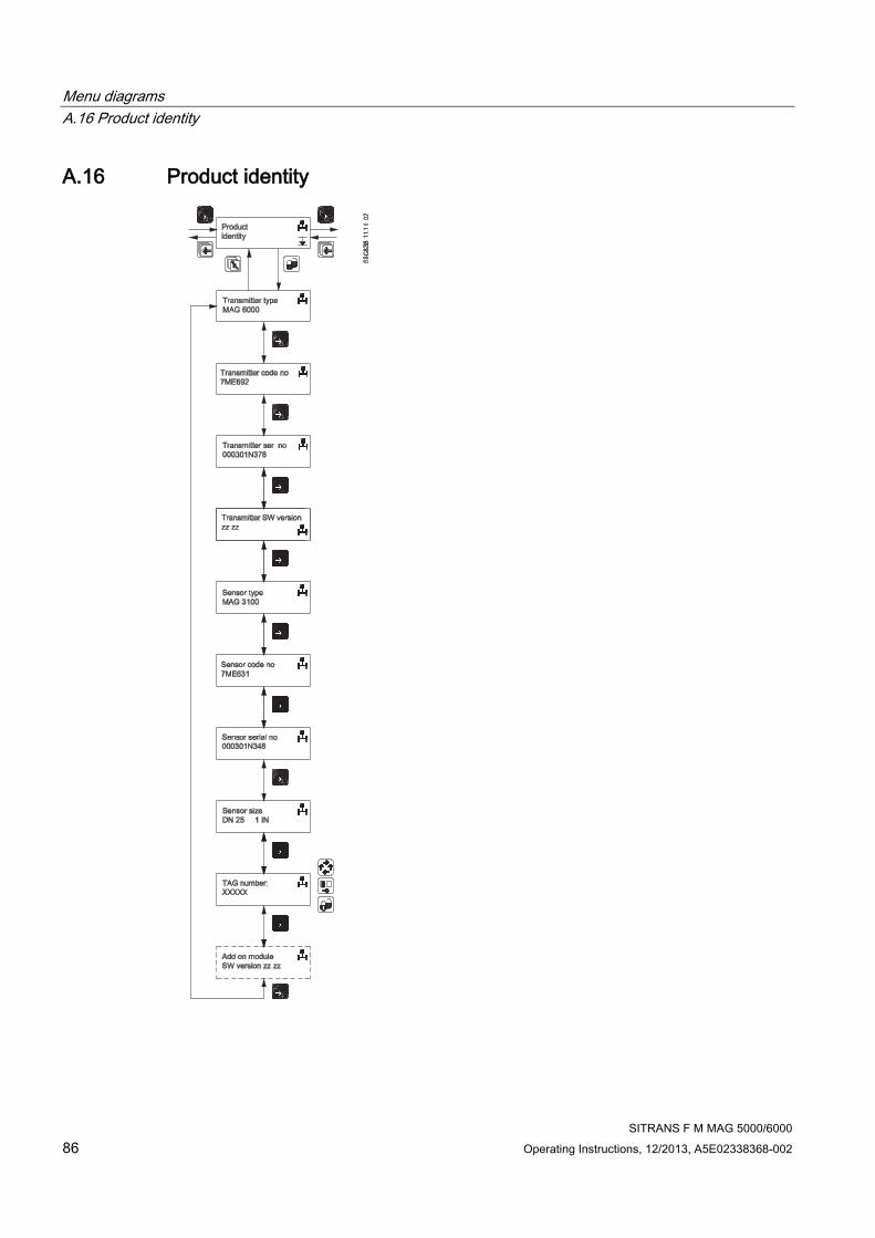
Menu diagrams
A.16 Product identity
SITRANS F M MAG 5000/6000
86 Operating Instructions, 12/2013, A5E02338368-002
A.16 Product identity

Menu diagrams
A.17 Add-on communication module
SITRANS F M MAG 5000/6000
Operating Instructions, 12/2013, A5E02338368-002 87
A.17 Add-on communication module
Example: HART
Note
Burst mode is not available with HART communication
A.18 Cleaning
Note
Relay outputs
If cleaning unit is installed, relay outputs must always be used to operate cleaning.
Relay outputs cannot be used for other purposes

Menu diagrams
A.19 MAG 5000/6000 CT menu overview
SITRANS F M MAG 5000/6000
88 Operating Instructions, 12/2013, A5E02338368-002
A.19 MAG 5000/6000 CT menu overview
Figure A-1 Overview MAG 5000 CT and MAG 6000 CT (part 1)
1) Factory-set password: 1000
2) Not visible when CT mode is "Hot water"
Figure A-2 Overview MAG 5000 CT and MAG 6000 CT (part 2)

Menu diagrams
A.20 Change password
SITRANS F M MAG 5000/6000
Operating Instructions, 12/2013, A5E02338368-002 89
Note
Sealing
Menus marked with gray are locked when transmitter is sealed.
A.20 Change password


SITRANS F M MAG 5000/6000
Operating Instructions, 12/2013, A5E02338368-002 91
B Factory settings B
B.1 Transmitter factory settings
The factory settings shown on the following pages apply to MAG 5000/6000 as well as
MAG 6000 I.
Menu item Parameter Factory
settings
Options More info
Password
Password 1000 1000 ... 9999 Changing
password
(Page 42)
and Change
password
(Page 89)
Basic settings Flow direction Positive Positive, negative Changing
basic
settings
(Page 43)
Qmax Sensor size
dependent
Sensor size dependent
volume unit Sensor size dependent
m3, ml, l , hl, kl, Ml, ft 3, in3, US G, US kG, US MG, US BBL, UK G, UK kG, UK MG, ? (customer unit)
time unit Sensor size dependent
Sec., min., hour, day, ? (customer unit)
Totalizer 1 Forward Forward, reverse, net
Totalizer 1 unit Sensor size dependent
m3, ml, l , hl, kl, Ml, ft 3, in3, US G, US kG, US MG, US BBL, UK G, UK kG, UK MG, ? (customer unit)
Totalizer 2 Reverse Forward, reverse, net
Totalizer 2 unit Sensor size dependent
m3, ml, l , hl, kl, Ml, ft 3, in3, US G, US kG, US MG, US BBL, UK G, UK kG, UK MG, ? (customer unit)
Low flow cut-off 1.5% 0 ... 9.9%
Empty pipe Off On, Off
Velocity unit m/s m, mm, cm, dm, ft , in
per s, min, h, d, ? (customer unit)
Error level Warning Fatal, permanent, warning
Output Current output Off for
MAG5000/
6000
On for
MAG6000I
Namur
On/off, Unidirectional/bidirectional, 0...20
mA/4...20 mA/4...20 mA + Alarm
Output
settings
(Page 47)
Alarm level Low High/Low
Alarm diff. No Yes/No
Time constant 5 s 0.1...30 s

Factory settings
B.1 Transmitter factory settings
SITRANS F M MAG 5000/6000
92 Operating Instructions, 12/2013, A5E02338368-002
Menu item Parameter Factory
settings
Options More info
Digital output Pulse Error, direction/limit, batch, frequency, pulse, error
number, off
Digital
output -
pulse
(Page 78)
Relay output Error level Error, direction/limit, cleaning, error number, off Error level
(Page 78)
Direction/limit
switch
Off
1 setpoint, 2 setpoints
Direction/lim
it (Page 79)
Setpoints 0% -100 ... +100%
Hysteresis 5% 0.0 ... 100%
Batch
Off
Batch
(Page 79)
Batch quantity
0
Sensor size dependent
Batch
compensation
0 -100 ... +100 m3
Batch counter Down Up, down
Frequency Off 500 Hz, 1 kHz, 5 kHz, 10 kHz Digital
output -
frequency
(Page 78)
Time constant 5 s 0.1 ... 30 s
Pulse On Digital
output -
pulse
(Page 78)
Pulse polarity Positive Positive, negative
Pulse width 66 ms 64 μs 130 μs, 260 μs, 510 μs, 1.0 ms, 2.0 ms, 4.1 ms, 8.2 ms, 16 ms, 33, ms, 66 ms, 130 ms, 260 ms, 520 ms, 1.0 s, 2.1 s, 4.2 s
Volume/pulse Sensor size dependent
Dimension-dependent
Time constant 0.1 s 0.1 ... 30 s
External input External input Off Batch, reset totalizer, freeze output, forced output,
off
External
input
(Page 80) Batch Start Start, hold/continue, stop, Qmax 2

Factory settings
B.2 50 Hz Dimension dependent
SITRANS F M MAG 5000/6000
Operating Instructions, 12/2013, A5E02338368-002 93
Menu item Parameter Factory
settings
Options More info
Sensor
characteristics
Correction factor 1 0.85 ... 2.00 Sensor
characteristi
cs
(Page 81)
Language Language English English, German, French, Danish, Swedish,
Finnish, Spanish, Russian, Italian, Portuguese,
Polish
Changing
language
(Page 46)
Operator menu Primary field Flow rate Flow rate, Totalizer 1, Totalizer 2 Changing
operator
menu setup
(Page 45)
Title/subtitle lines Flow rate Flow rate, Flow velocity, Qmax, Totalizer 1,
Totalizer 2, Totalizer 1 reset, Totalizer 2 reset,
Batch start/paused/stop, Batch cycle counter,
Batch cycle counter reset, Sensor size, Sensor
type, Error pending, Status log, Tag No.
B.2 50 Hz Dimension dependent
50 Hz Dimension dependent factory settings MAG 1100, MAG1100F, MAG 3100, MAG 3100 P and MAG 5100W with M20 cable glands
DN Qmax*
Factory
settting
MAG 5100 W (Order no. 7ME6520) MAG 1100, MAG 1100 F, 5100 W
(Order no. 7ME6580) MAG 3100,
3100 P
unit
mm (inch) min. max. min. max.
2 (1/12) 30 - - 3.903623 156.1448 l/h
3 (1/8) 70 - - 6.361726 254.469 l/h
6 (1/4) 300 - - 25.44691 1017.876 l/h
10 (3/8) 900 - - 70.68584 2827.433 l/h
15 (½) 2000 - - 159.0432 6361.725 l/h
25 (1) 5000 441.7865 17671.45 441.7865 17671.45 l/h
40 (1½) 12 1.130974 45.23893 1.130974 45.23893 m3/h
50 (2) 20 1.574527 62.98107 1.767146 70.68583 m3/h
65 (2½) 30 2.499681 99.98723 2.986477 119.459 m3/h
80 (3) 50 4.003646 160.1458 4.523894 180.9557 m3/h
100(4) 120 6.252163 250.0864 7.068584 282.7433 m3/h
125 (5) 180 10.00647 400.2585 11.04467 441.7864 m3/h
150 (6) 250 15.74527 629.8107 15.90432 636.1725 m3/h
200(8) 400 24.93797 997.5184 28.27434 1130.973 m3/h
250(10) 700 40.00377 1600.15 44.17865 1767.145 m3/h
300 (12) 1000 62.50395 2500.157 63.61726 254469 m3/h
350 (14) 1200 86.59015 3463.605 86.59015 3463.605 m3/h

Factory settings
B.3 60 Hz Dimension dependent
SITRANS F M MAG 5000/6000
94 Operating Instructions, 12/2013, A5E02338368-002
DN Qmax*
Factory
settting
MAG 5100 W (Order no. 7ME6520) MAG 1100, MAG 1100 F, 5100 W
(Order no. 7ME6580) MAG 3100,
3100 P
unit
mm (inch) min. max. min. max.
400 (16) 1800 113.0974 4523.893 113.0974 4523.893 m3/h
450 (18) 2000 143.1389 5725.552 143.1389 5725.552 m3/h
500 (20) 3000 176.7146 7068.583 176.7146 7068.583 m3/h
600 (24) 4000 254.4691 10178.76 254.4691 10178.76 m3/h
700 (28) 4500 346.3606 13854,42 346.3606 13854.42 m3/h
750 (30) 5000 397.6079 15904.31 397.6079 15904.31 m3/h
800 (32) 7000 452.3894 18095,57 452.3894 18095.57 m3/h
900 (36) 9000 572.5553 22902,21 572.5553 22902.21 m3/h
1000 (40) 12000 706.8584 28274.33 706.8584 28274.33 m3/h
1050 (42) 12000 706.8584 28274.33 706.8584 28274.33 m3/h
1100 (44) 14000 855.986 34211.94 855.2986 3421194 m3/h
1200 (48) 15000 1017.877 40715.04 1017.877 40715.04 m3/h
1400 (54) 25000 - - 1385.443 55417.69 m3/h
1500 (60) 30000 - - 1590.432 63617.25 m3/h
1600 (66) 35000 - - 1809.558 72382.29 m3/h
1800 (72) 40000 - - 2290.222 91608.84 m3/h
2000 (78) 45000 - - 2827.434 113097.3 m3/h
2200 (90) 50000 - - 3421,195 136847.7 m3/h
2400 (96) 55000 - - 4071.505 162860.1 m3/h
2600 (102) 60000 - - 4778.363 191134.4 m3/h
280 (114) 65000 - - 5541.77 221670.7 m3/h
3000 (120) 70000 - - 6361.726 254469 m3/h
* The min. and max. amount values show mathematical values and do not indicate
measurement accuracy

Factory settings
B.3 60 Hz Dimension dependent
SITRANS F M MAG 5000/6000
Operating Instructions, 12/2013, A5E02338368-002 95
B.3 60 Hz Dimension dependent
60 Hz Dimension dependent factory settings MAG 1100, MAG1100F, MAG 3100, MAG 3100 P and MAG 5100W with ½" NPT cable glands
DN Qmax.
Factory
setting*
MAG 5100 W (Order no. 7ME6520) MAG 1100, MAG 1100 F, 5100 W
(Order no. 7ME6580) MAG 3100,
3100 P
unit
mm (inch) min. max. min. max.
2 (1/12) 0.14 - - 0.01718714 0.6874852 US GPM
3 (1/8) 0.31 - - 0.02800984 1.120393 US GPM
6 (1/4) 1.4 - - 0.1120394 4.481573 US GPM
10 (3/8) 4 - - 0.3112204 12.44881 US GPM
15 (½) 9 - - 0.7002459 28.0 US GPM
25 (1) 23 1.945128 77.80509 1.945128 77.80509 US GPM
40 (1½) 53 4.979526 199.181 4.979526 199.181 US GPM
50 (2) 89 6.932434 277.2973 7.78051 311.2203 US GPM
65 (2½) 133 11.00577 440.2305 13.14907 525.9624 US GPM
80 (3) 221 17.62753 705.1008 19.91811 796.7241 US GPM
100(4) 529 27.52745 1101.097 31.12204 1244.881 US GPM
125 (5) 793 44.05714 1762.285 48.62819 1945.127 US GPM
150 (6) 1101 69.32434 2772.973 70.02459
200 (8) 1762 109.7986 4391.941 4979.525
250 (10) 3083 176.1313 7045.251 194.5128
300 (12) 4403 275.1967 11007.86 280.0984 11203.93 US GPM
350 (14) 5284 381.245 15249.79 381.245 15249.79 US GPM
400 (16) 7926 497.9526 19918.1 497.9526 19918.1 US GPM
450 (18) 8806 630.2213 25208.84 630.2213 25208.84 US GPM
500 (20) 13209 778.051 31122.03 778.051 31122.03 US GPM
600 (24) 17612 1120.394 44815.73 1120.394 44815.73 US GPM
700 (28) 19813 1524.98 60999.19 1524.98 60999.19 US GPM
750 (30) 22015 1750.615 70024.58 1750.615 70024.58 US GPM
800 (32) 3082 1991.811 79672.4 1991.811 79672.41 US GPM
900 (36) 39626 2520.885 100835.3 2520.885 100835.3 US GPM
1000 (40) 52835 3112.204 124488.1 3112.204 124488.1 US GPM
1050 (42) 52835 3112.204 137248.1 3112.204 124488.1 US GPM
1100 (44) 61641 3765.767 150630.6 3765.767 150630.6 US GPM
1200 (48) 66044 4481.574 179262.9 4481.574 179262.9 US GPM
1400 (54) 110072 - - 6099.92 243996.7 US GPM
1500 (60) 1320867 - - 7002.459 280098.3 US GPM
1600 (66) 154101 - - 7967.242 318689.6 US GPM

Factory settings
B.4 50 Hz Dimension dependent batch and pulse output settings
SITRANS F M MAG 5000/6000
96 Operating Instructions, 12/2013, A5E02338368-002
DN Qmax.
Factory
setting*
MAG 5100 W (Order no. 7ME6520) MAG 1100, MAG 1100 F, 5100 W
(Order no. 7ME6580) MAG 3100,
3100 P
unit
mm (inch) min. max. min. max.
1800 (72) 176115 - - 10083.54 403341.5 US GPM
2000 (78) 198130 - - 12448.82 497952.5 US GPM
2200 (90) 220144 - - 15063.07 602522.6
242158 - 17926.3 717051.7
2600 (102) 264173 - - 21038.5 841539.8
2800 (114) 286187 - - 24399.68 975987
3000 (120) 308201 - - 28009.84 1120393
* Factory setting sets Qmax to a metric unit (see previous table). The values here are
converted to rounded off US GPM.
B.4 50 Hz Dimension dependent batch and pulse output settings
50 Hz Dimension dependent factory settings MAG 1100, MAG1100F, MAG 3100, MAG 3100 P and MAG 5100W with ½" NPT cable glands
6DN Volume/pulse or batch quantity* Factory setting
MAG 5100 W (Order no.
7ME6520)
MAG 1100, MAG 1100 F, 5100 W (Order
no. 7ME6580) MAG 3100, 3100 P
Volume/
pulse &
batch
amount
Pulse &
batch
unit
Totalize
r
unit mm (inch) min. max. min. max.
2 (1/12) - - 3.61466 μl 94.75103 l 0.1 ml ml
3 (1/8) - - 5.890487 μl 154.4155 l 0.1 ml ml
6 (1/4) - - 23.56195 μl 617.6622 l 1 l l
10 (3/8) - - 65.44985 μl 1.715728 m3 1 l l
15 (½) - - 147.2622 μl 3.860389 m3 1 l l
25 (1) 409.0616 μl 10.7233 m3 409.0616 μl 10.7233 m3 10 l l**
40 (1½) 1.047198 ml 27.45165 m3 1.047198 ml 27.45165 m3 10 l l**
50 (2) 1.457896 ml 38.21785 m3 1.636247 ml 42.89321 m3 10 l l**
65 (2½) 2.31452 ml 60.67373 m3 2.765257 ml 72.48952 m3 100 l l**
80 (3) 3.70708 ml 97.17886 m3 4.188791 ml 109.8066 m3 100 l l**
100(4) 5.789039 ml 151.7561 m3 6.544985 ml 171.5728 m3 100 l l**
125 (5) 9.265244 ml 242.8828 m3 10.22654 ml 268.0825 m3 100 l m3
150 (6) 14.57896 ml 382.1785 m3 14.72622 ml 386.0389 m3 100 l m3
200 (8) 23.09071 ml 605.309 m3 26.17994 ml 686.2913 m3 1 m3 m3

Factory settings
B.4 50 Hz Dimension dependent batch and pulse output settings
SITRANS F M MAG 5000/6000
Operating Instructions, 12/2013, A5E02338368-002 97
6DN Volume/pulse or batch quantity* Factory setting
MAG 5100 W (Order no.
7ME6520)
MAG 1100, MAG 1100 F, 5100 W (Order
no. 7ME6580) MAG 3100, 3100 P
Volume/
pulse &
batch
amount
Pulse &
batch
unit
Totalize
r
unit mm (inch) min. max. min. max.
250 (10) 37.04053 ml 970.995 m3 40.90616 ml 1072.33 m3 1 m3 m3
300 (12) 57.87403 ml 1517.132 m3 58.90487 ml 1544.155 m3 1 m3 m3
350 (14) 80.17607 ml 2101.767 m3 80.17607 ml 210.7671 m3 1 m3 m3
400 (16) 104.7198 ml 2745.165 m3 104.7198 ml 2745.165 m3 1 m3 m3
450 (18) 132.536 ml 3474.35 m3 132.536 ml 3474.35 m3 1 m3 m3
500 (20) 163.6247 ml 4289.321 m3 163.6247 ml 4289.321 m3 10 m3 m3
600 (24) 235.6195 ml 6176.622 m3 235.6195 ml 6176.622 m3 10 m3 m3
700 (28) 320.7043 ml 8407.069 m3 320.7143 ml 8407.069 m3 10 m3 m3
750 (30) 368.1554 ml 9650.972 m3 368.1554 ml 9650.972 m3 10 m3 m3
800 (32) 418.8791 ml 10980.66 m3 418.8791 ml 10980.66 m3 10 m3 m3
900 (36) 530.1438 ml 13897.4 m3 530.1438 ml 13897.4 m3 10 m3 m3
1000 (40) 654.4985 ml 17157.28 m3 654.4985 ml 17157.28 m3 10 m3 m3
1050 (42) 654.4985 ml 17157.28 m3 654.4985 ml 17157.28 m3 10 m3 m3
1100 (44) 79.94321 ml 20760.31 m3 791.9432 ml 20760.31 m3 10 m3 m3
1200 (48) 942.4778 ml 24706.48 m3 942.4778 ml 24706.48 m3 10 m3 m3
1400 (54) - - 1.282817 l 33628.27 m3 10 m3 m3
1500 (60) - - 1.472622 l 38603.89 m3 10 m3 m3
1600 (66) - - 1.675517 l 43922.64 m3 10 m3 m3
1800 (72) - - 2.120576 l 55589.6 m3 10 m3 m3
2000 (78) - - 2.617994 l 68629.13 m3 10 m3 m3
2200 (90) - - 3.167773 l 83041.25 m3 10 m3 m3
2400 (96) - - 3.769912 l 98825.9 m3 10 m3 m3
2600 (102) - - 4.4241 l 115983. m3 10 m3 m3
2800 (114) - - 5.131268 l 134513.1 m3 10 m3 m3
3000 (120) - - 5.890487 l 154415.5 m3 10 m3 m3
* The min. and max. amount values show mathematical values and do not indicate
measurement accuracy.
** For CT devices the totalizer 1 unit is in m3

Factory settings
B.5 60 Hz Dimension dependent batch and pulse output settings
SITRANS F M MAG 5000/6000
98 Operating Instructions, 12/2013, A5E02338368-002
B.5 60 Hz Dimension dependent batch and pulse output settings
60 Hz Dimension dependent factory settings MAG 1100, MAG1100F, MAG 3100, MAG 3100 P and MAG 5100W with ½" NPT cable glands
DN Volume/pulse or batch quantity
MAG 5100 W (Order no. 7ME6520) MAG 1100, MAG 1100 F, 5100 W (Order no. 7ME6580)
MAG 3100, 3100 P
mm (inch) US G min. US G max. US G min. US G max.
2 (1/12) - - 0.00000095484069 25.03057
3 (1/8) - - 0.000001556102 40.79227
6 (1/4) - - 0.000006224408 163.1691
10 (3/8) - - 0.00001729003 453.2475
15 (½) - - 0.00003890255 1019.806
25 (1) 0.0001080627 2832.796 0.0001080627 2832.796
40 (1½) 0.0002766404 7251.96 0.0002766404 7251.96
50 (2) 0.0003851353 10096.08 0.0004322506 11331.18
65 (2½) 0.0006114314 16028.3 0.0007305034 19149.7
80 (3) 0.0009793068 25671.93 0.001106562 29007.84
100(4) 0.001529303 40089.74 0.001729003 45324.75
125 (5) 0.002447619 64162.85 0.002701566 70819.92
150 (6) 0.003851353 100960.8 0.003890255 101980.6
200 (8) 0.00609992 159905.7 0.006916009 181299
250 (10) 0.009785071 256509.7 0.01080627 283279.6
300 (12) 0.01528871 400784.1 0.01556102 407922.7
350 (14) 0.02118028 555228.2 0.02118028 555228.2
400 (16) 0.02766404 725196 0.02766404 725196
450 (18) 0.0350123 917826.2 0.0350123 917826.2
500 (20) 0.04322506 1133118 0.04322506 1133118
600 (24) 0.06224408 1631691 0.06224408 1631691
700 (28) 0.0847211 2220912 0.0847211 2220912
750 (30) 0.09725637 2549517 0.09725637 2549517
800 (32) 0.1106562 2900784 0.1106562 2900784
900 (36) 0.1400492 3671304 0.1400492 3671304
1000 (40) 0.1729003 4532475 0.1729003 4532475
1050 (42) 0.1729003 4532475 0.1729003 4532475
1100 (44) 0.2092093 5484294 0.2092093 5484294
1200 (48) 0.2489763 6526764 0.2489763 6526764
1400 (54) - - 0.3388844 8883651
1500 (60) - - 0.3890255 10198060
1600 (66) - - 0.4426246 11603130
1800 (72) - - 0.5601967 14685210

Factory settings
B.5 60 Hz Dimension dependent batch and pulse output settings
SITRANS F M MAG 5000/6000
Operating Instructions, 12/2013, A5E02338368-002 99
DN Volume/pulse or batch quantity
MAG 5100 W (Order no. 7ME6520) MAG 1100, MAG 1100 F, 5100 W (Order no. 7ME6580)
MAG 3100, 3100 P
mm (inch) US G min. US G max. US G min. US G max.
2000 (78) - - 0.6916009 18129900
2200 (90) 0.836837 21937170
2400 (96) 0.995906 26107050
2600 (102) 1.168806 30639530
2800 (114) 1.355538 35534600
3000 (120) 1.556102 40792270


SITRANS F M MAG 5000/6000
Operating Instructions, 12/2013, A5E02338368-002 101
C Approvals/Certificates C
All certificates are posted on the Internet. Additionally, the CE Declaration of Conformity as
well as ATEX approvals are available on the SITRANS F literature CD-ROM.
Certificates (http://support.automation.siemens.com/WW/view/en/10806951/134200)

Approvals/Certificates
SITRANS F M MAG 5000/6000
102 Operating Instructions, 12/2013, A5E02338368-002

SITRANS F M MAG 5000/6000
Operating Instructions, 12/2013, A5E02338368-002 103
Index
A
Add-on module, 15
Add-on modules
Electrical connection:Add-on modules, 38
Alarm differentiation, 47
Alarm level, 47
C
Communication module, (See Add-on module)
Compliance, 11
Contact person, 9
Customer Support Hotline, 58
D
Decontamination, 59
Device
Identification, 8
Inspection, 7
Diagnostic functions, 53
E
Electrical connection, 38
Error handling, 53
H
Hotline, 58
I
Installation
Indoor/outdoor, 19
Internet
Contact person, 9, 59
Flow documentation, 9
Support, 59
Introduction, 7
L
Laws and directives, 11
M
Mains supply, 35
Maintenance, 57
P
Protective conductor terminal, 35
Protective earth, 35
R
Recalibration, 60
Repair, 58
Return procedures, 59
S
Safety
Instrument safety standards, 11
Safety notes, 11
Service, 58, 59
Support, 59
System components, 15
W
Wire insulation, 35

Siemens A/S Flow InstrumentsNordborgvej 81DK-6430 Nordborg
Subject to change without prior noticeOrder No.: A5E02338368Lit. No.: A5E02338368-002© Siemens AG 12.2013
www.siemens.com/processautomation
For more information
www.siemens.com/flow
A5E02338368A5E02338368