Embed Size (px)
Citation preview

Intelligent Transportation Systems Bay County Advanced Traffic Management System Phase II Project
Site Visit Report March 8, 2005, Site Survey – Examination of the Hathaway Bridge Project’s Existing Intelligent Transportation System Devices March 25, 2005 Version 1
Prepared for: Florida Department of Transportation Traffic Engineering and Operations Office Intelligent Transportation Systems (ITS) Section 605 Suwannee Street, M.S. 90 Tallahassee, Florida 32399-0450 (850) 410-5600

Bay County ATMS Phase II Project March 8, 2005, Site Visit Report
Version 1 – March 25, 2005 i
DOCUMENT CONTROL PANEL
File Name:
Bay County Advanced Traffic Management System Phase II Project: Site Visit Report – March 8, 2005, Site Survey – Examination of the Hathaway Bridge Project’s Existing Intelligent Transportation System Devices
File Location: W:\ITS Program\ITS GC\TWO37-Bay County ATMS\Site Visit Reports and Supporting Documentation\050325 TWO37 3-8-05 Site Visit Rprt V1.pdf
Deliverable Number:
Version Number: 1
Name Date
Ron Meyer, PBS&J March 17, 2005
Created By:
Ron Meyer, PBS&J March 21, 2005
Tahira Faquir, PBS&J March 22, 2005
David Chang, PBS&J March 24, 2005
Reviewed By:
Pam Hoke, PBS&J March 19, 2005
Dave Hodges, PBS&J March 23, 2005
Pam Hoke, PBS&J March 23, 2005
Modified By:
Completed By: Pam Hoke, PBS&J March 25, 2005

Bay County ATMS Phase II Project March 8, 2005, Site Visit Report
Version 1 – March 25, 2005 ii
Table of Contents
List of Figures ........................................................................................... iii List of Acronyms....................................................................................... iv 1. Introduction ..................................................................................... 1 2. Purposes of the Site Visits............................................................. 2 3. Schedule and Time Line................................................................. 3 4. Activities Conducted during the Site Visits ................................. 4
4.1 Closed-Circuit Television Locations.................................................. 4 4.2 Metric Engineering Field Office Intelligent Transportation
System Equipment .............................................................................. 7 4.3 Dynamic Message Sign Site ............................................................. 10 4.4 Hathaway Bridge Closed-Circuit Television / Road Weather
Information System Site ................................................................... 13 5. Conclusion ....................................................................................18
5.1 Recommendations ............................................................................ 19

Bay County ATMS Phase II Project March 8, 2005, Site Visit Report
Version 1 – March 25, 2005 iii
List of Figures
Figure 4.1 – CCTV Location .....................................................................................4 Figure 4.2 – CCTV Cabinet Installation – Cabinet Interior ......................................5 Figure 4.3 – CCTV Cabinet Installation – Close-Up of Cabinet Interior..................5 Figure 4.4 – Metric Engineering Field Office Command and Control Room...........7 Figure 4.5 – CCTV Control CPU and Multiplexer Panel..........................................8 Figure 4.6 – Fiber Optic Transceivers .......................................................................8 Figure 4.7 – DMS Installation Location ..................................................................10 Figure 4.8 – Cabinet Enclosure................................................................................11 Figure 4.9 – DMS Site Field Cabinet Fiber Transceiver .........................................11 Figure 4.10 – DMS Controller and Panel inside the Sign Cabinet..........................12 Figure 4.11 – CCTV / RWIS Site on the Hathaway Bridge....................................13 Figure 4.12 – Hathaway Bridge Camera and Lowering Device..............................14 Figure 4.13 – Hathaway Bridge RWIS Sensors ......................................................14 Figure 4.14 – RWIS / CCTV Cabinet (View 1) ......................................................15 Figure 4.15 – RWIS / CCTV Cabinet (View 2) ......................................................16

Bay County ATMS Phase II Project March 8, 2005, Site Visit Report
Version 1 – March 25, 2005 iv
List of Acronyms ATMS .................................................................................Advanced Traffic Management System
CCTV....................................................................................................... Closed-Circuit Television
CPU............................................................................................................. Central Processing Unit
DMS.............................................................................................................Dynamic Message Sign
EIS......................................................................................................Electronic Integrated Systems
FDOT .................................................................................... Florida Department of Transportation
IFS......................................................................................................... International Fiber Systems
ITS................................................................................................Intelligent Transportation System
KDS...................................................................................................................Korea Data Systems
LED.................................................................................................................Light-Emitting Diode
PTZ ............................................................................................................................Pan-Tilt-Zoom
QTY .................................................................................................................................... Quantity
RTWIN .................................................................Road and Traffic Weather Information Network
RWIS..........................................................................................Road Weather Information System
SP4 .............................................................................................................................Service Pack 4
TEOO............................................................................ Traffic Engineering and Operations Office
VAC ..................................................................................................... Volts of Alternating Current

Bay County ATMS Phase II Project March 8, 2005, Site Visit Report
Version 1 – March 25, 2005 1
1. Introduction Bay County’s advanced traffic management system (ATMS) project includes the integration of existing intelligent transportation system (ITS) devices that were deployed on and around the Hathaway Bridge under a prior construction project. In order to fully understand the systems currently deployed on and around the bridge, submittal information concerning the ITS equipment on the Hathaway Bridge project was requested and subsequently reviewed. During review, personnel familiar with the project expressed concern that the submittal documents did not accurately represent the devices that had been installed on the prior project. It was decided that a site visit was necessary to determine whether the submittal data accurately represented the material installed on and around the bridge. A site visit was conducted on March 8, 2005, to investigate the suspected discrepancy between documentation provided for reference and what was understood to be deployed at this time on the bridge. This report provides an overview of the trip conducted and the details considered during the survey.

Bay County ATMS Phase II Project March 8, 2005, Site Visit Report
Version 1 – March 25, 2005 2
2. Purposes of the Site Visit The purposes of the site visit were to: • Survey the ITS device locations on the Hathaway Bridge and determine the types,
manufacturers, and model numbers of the ITS components • Survey the ITS equipment currently installed in the Metric Engineering field office to
determine types, manufacturers, and model numbers • Survey other ITS equipment in the immediate vicinity of the Hathaway Bridge and
identify any issues relating to the integration of the Hathaway Bridge ITS components with the Bay County ATMS.

Bay County ATMS Phase II Project March 8, 2005, Site Visit Report
Version 1 – March 25, 2005 3
3. Schedule and Time Line A single-day site visit to Bay County was conducted on March 8, 2005. The investigative team was comprised of David Chang and Ron Meyer, who represented the Florida Department of Transportation’s (FDOT) Traffic Engineering and Operations Office (TEOO) ITS Section, and Keith Bryant, Jerry Kearney, and Wayne Comeau, who represented the Bay County Traffic Engineering Division. The team met during the morning and proceeded to visit the Metric Engineering field office on the west end of the Hathaway Bridge, a dynamic message sign (DMS) located on U.S. Highway 98 to the west of the bridge, a closed-circuit television (CCTV) site on U.S. Highway 98 to the west of the bridge, and the road weather information system (RWIS)/CCTV site on the westbound shoulder of the Hathaway Bridge. Bryant, Chang, and Meyer also met with Mr. Steve Potter, FDOT District 3 Construction Engineer for a brief and general discussion regarding the project. In this conversation, Mr. Potter indicated that certain design aspects of the project had been changed during construction. These changes included the deletion of radar detection systems that were originally included in the bridge project as well as changes made to the communication infrastructure. Mr. Potter was asked if he could search for additional documentation on the project, specifically:
• Project plan sheets (as-builts or red-line markups showing accurate detail). • Submittal data, if any, on the devices that are actually installed (the original submittals
that were received by FDOT TEOO ITS section does not match the equipment in the field).
• Drawings and/or documentation for the field cabinets (there was nothing in any of the roadside ITS-related cabinets that the team visited).
As of this writing, no additional documents have been provided to the FDOT TEOO ITS section. Site visits at these locations took place between approximately 10:00 a.m. and 4:00 p.m. local time.

Bay County ATMS Phase II Project March 8, 2005, Site Visit Report
Version 1 – March 25, 2005 4
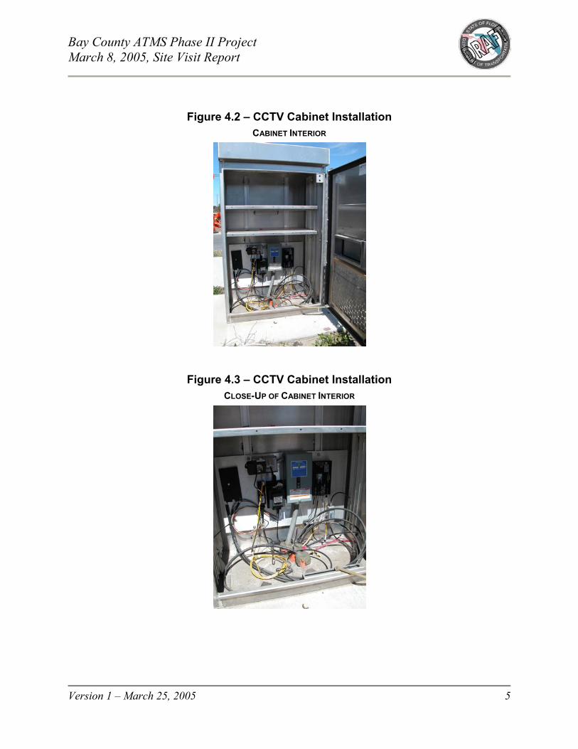
4. Activities Conducted during the Site Visit 4.1 Closed-Circuit Television Locations The CCTV locations visited were surveyed to determine the type of equipment currently installed. Photographs were taken of the cabinet and related components. Figures 4.1 through 4.3 are representative of the photographs taken of the currently installed CCTV sites in the vicinity of the bridge.
Figure 4.1 – CCTV Location
U.S. HIGHWAY 98 – WEST OF HATHAWAY BRIDGE
Bay County ATMS Phase II Project March 8, 2005, Site Visit Report
Version 1 – March 25, 2005 5
Figure 4.2 – CCTV Cabinet Installation
CABINET INTERIOR
Figure 4.3 – CCTV Cabinet Installation
CLOSE-UP OF CABINET INTERIOR

Bay County ATMS Phase II Project March 8, 2005, Site Visit Report
Version 1 – March 25, 2005 6
It was concluded that the following materials are currently in use at the CCTV sites on this project: • Camera Equipment
o Vicon® Surveyor pressurized dome1 o Wall mount o Pole mount adapter o Composite camera cable o 24-Volt alternating current (VAC) transformer for camera power in the cabinet o EDCO CX-06-BNCY for coax cable suppression2
• Fiber Optic Transceiver
o International Fiber Systems (IFS®)3 Model VDT14130WDM video transmitter/data transceiver
• Fiber Optic Cabling and Accessories
o Berk-Tek single-mode optical cable Model No. OPDD6B0364 o 36-Strand outside plant cable o Splice panel o Four-port Gator Patch™5 ST®6 patch panel
1 Vicon is a registered trademark of Vicon Industries, Inc. More information regarding Vicon products is available
online at http://www.vicon-cctv.com/. 2 More information regarding EDCO products is available online at http://www.edcosurge.com/products/index.asp. 3 IFS is a registered trademark of International Fiber Systems, Incorporated. 4 More information regarding Berk-Tek products is available online at http://www.berktek.com/products/. 5 Gator Patch is a trademark of Fiber Connections, Inc. 6 ST is a registered trademark of Lucent Technologies.

Bay County ATMS Phase II Project March 8, 2005, Site Visit Report
Version 1 – March 25, 2005 7
4.2 Metric Engineering Field Office Intelligent Transportation System Equipment
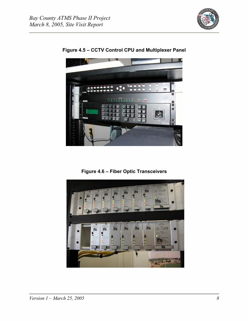
The command and control of existing ITS devices on and around the Hathaway Bridge is concentrated in an equipment rack that is currently located in the Metric Engineering field office, located at the west end of the Hathaway Bridge. This location was visited and surveyed to determine the type of equipment currently installed. Figures 4.4 through 4.6 are representative of the photographs taken of the equipment rack in the field office.
Figure 4.4 – Metric Engineering Field Office Command and Control Room
Bay County ATMS Phase II Project March 8, 2005, Site Visit Report
Version 1 – March 25, 2005 8
Figure 4.5 – CCTV Control CPU and Multiplexer Panel
Figure 4.6 – Fiber Optic Transceivers

Bay County ATMS Phase II Project March 8, 2005, Site Visit Report
Version 1 – March 25, 2005 9
It was concluded that the following materials are currently in use on this project at the Metric Engineering field office. • Camera Equipment
o Vicon Model No. V1422™ central processing unit (CPU)-based control and switching system7
o Vicon Model No. V1400X-IDL intelligent distribution line control unit o Vicon AurorA2000 digital multiplexer o Vicon Model No. V1400X-DVC-3 system console control station o Panasonic® television8
• Fiber Optic Equipment
o IFS Model No. VDR14130WDM rack-mounted video receiver/data transceivers (Quantity [QTY] 9)
o IFS Model No. D7130WDMB Ethernet®9 optical transceiver (QTY 4) o R3 rack mount card cage (QTY 2) o Splice tray o Patch cords
• Server Equipment
o Dell™ PowerEdge™ 600SC10 with Microsoft® Windows® 2000 Server11 v.5.0.2195, Service Pack 4 [SP4], Build 2195
o Keyboard o Mouse o Korea Data Systems (KDS) 17-inch monitor12
7 V1422 is a trademark of Vicon Industries, Inc. 8 Panasonic is a registered trademark of Matsushita Electric Industrial Co., Ltd. 9 Ethernet is a registered trademark of Xerox Corporation. 10 Dell and PowerEdge are trademarks of Dell Computer Corporation. 11 Microsoft and Windows are registered trademarks of Microsoft Corporation in the United States and/or other
countries. 12 More information regarding KDS USA products is available online at http://www.kdsusa.com.

Bay County ATMS Phase II Project March 8, 2005, Site Visit Report
Version 1 – March 25, 2005 10
• Server Applications include: o Dynamic message sign controller software (i.e., Vultron Manager version 1.2.37
with dial-up) o Road weather information system software (i.e., Nu-Metrics® Road and Traffic
Weather Information Network [RTWIN©] display v1.0)13 Command and control of a camera was verified during the site visit by selecting and commanding a remote pan-tilt-zoon (PTZ) camera that could be observed on the monitor at the site. Command and control of the DMS on U.S. Highway 98 was verified by placing a test message on the sign. The RWIS was not functional. 4.3 Dynamic Message Sign Site The DMS location on U.S. Highway 98 west of the Hathaway Bridge was visited to determine the type of equipment currently installed. Photographs were taken of the cabinet and related components. Figures 4.7 through 4.10 are representative of the photographs taken of the currently installed DMS sites in the vicinity of the bridge.
Figure 4.7 – DMS Installation Location
13 Nu-Metrics is a registered trademark of Nu-Metrics, Inc. © 2001 Nu-Metrics, Inc. – A Quixote Company.

Bay County ATMS Phase II Project March 8, 2005, Site Visit Report
Version 1 – March 25, 2005 11
Figure 4.8 – Cabinet Enclosure
Figure 4.9 – DMS Site Field Cabinet Fiber Transceiver

Bay County ATMS Phase II Project March 8, 2005, Site Visit Report
Version 1 – March 25, 2005 12
Figure 4.10 – DMS Controller and Panel inside the Sign Cabinet
It was concluded that the following materials are currently in use at the DMS sites on this project: • Vultron Model EO55A light-emitting diode (LED)-flip dot DMS • IFS Model No. D7130WDMA Ethernet optical transceiver • Fiber Optic Cabling and Accessories
o Berk-Tek single-mode optical cable Model No. OPDD6B036 o 36-Strand outside plant cable o Splice panel o Four-port Gator Patch ST patch panel

Bay County ATMS Phase II Project March 8, 2005, Site Visit Report
Version 1 – March 25, 2005 13
4.4 Hathaway Bridge Closed-Circuit Television / Road Weather Information System Site
The CCTV/RWIS location on the Hathaway Bridge was visited to determine the type of equipment currently installed. Photographs were taken of the cabinet and related components. Figures 4.11 through 4.15 depict the current CCTV/RWIS field site.
Figure 4.11 – CCTV / RWIS Site on the Hathaway Bridge

Bay County ATMS Phase II Project March 8, 2005, Site Visit Report
Version 1 – March 25, 2005 14
Figure 4.12 – Hathaway Bridge Camera and Lowering Device
Figure 4.13 – Hathaway Bridge RWIS Sensors

Bay County ATMS Phase II Project March 8, 2005, Site Visit Report
Version 1 – March 25, 2005 15
Figure 4.14 – RWIS / CCTV Cabinet
VIEW 1

Bay County ATMS Phase II Project March 8, 2005, Site Visit Report
Version 1 – March 25, 2005 16
Figure 4.15 – RWIS / CCTV Cabinet
VIEW 2
It was concluded that the following materials are currently in use at the CCTV/RWIS site on this project: • RWIS System (i.e., Nu-Metrics RTWIN system)
Note: It was not possible during this visit to identify the exact components of this system. The lack of organization within the cabinet interior; lack of clear identification markings on electronic components within the cabinet; and lack of any cabinet or equipment documentation on site prohibited the identification of all specific system components at this site. The RWIS was not functional during the site visit, and the circuit breaker that feeds power to the system appeared to be either tripped or placed in the OFF position. It was also mentioned that the external wind speed and direction sensor was physically blown off of the structure during the 2004 hurricane season.

Bay County ATMS Phase II Project March 8, 2005, Site Visit Report
Version 1 – March 25, 2005 17
• Camera Equipment
o Vicon Surveyor pressurized dome o Wall mount o Pole mount adapter o Composite camera cable o 24-VAC transformer for camera power in the cabinet o EDCO Model No. CX-06-BNCY for coaxial cable suppression o [MG]2 Lowering Device
• Fiber Optic Transceivers
o IFS Model No. D7130WDMA Ethernet optical transceiver for RWIS interconnect o IFS Model No. VDT14130WDM video transmitter/data transceiver for CCTV
interconnect
• Fiber Optic Cabling and Accessories
o Berk-Tek single-mode optical cable Model No. OPDD6B036 o 36-Strand outside plant cable o Splice panel o Four-port Gator Patch ST patch panel

Bay County ATMS Phase II Project March 8, 2005, Site Visit Report
Version 1 – March 25, 2005 18
5. Conclusion It was concluded that the submittal data and project documentation received to date by the FDOT’s TEOO ITS Section did not accurately represent the system devices or interconnect architecture as it is currently deployed. Discrepancies include the following: • Submittals indicate Ultrak®14 KD6 dome cameras and central control equipment.
Vicon Surveyor cameras and Vicon central control equipment are installed on the project.
• Submittals indicate Optelecom15 fiber optic equipment for center-to-field interconnect;
however, IFS equipment is installed. • Submittals and project plans indicate the installation of 24-count fiber, but 36-count
fiber is installed. Submittals also indicate the installation of Corning®16 fiber cable, but Berk-Tek cable is installed.
• Submittals show a Model No. 332 enclosure as the cabinet type. This is not what is
installed. • Submittals indicate the use of a 3M® dynamic messaging system,17 but Vultron
equipment is installed. • Submittals and plans indicate the installation of remote traffic microwave sensors
(RTMS) from Electronic Integrated Systems (EIS); however, no detectors are installed. In summary, the documentation that has been received to date by the TEOO ITS Section is almost entirely inaccurate with respect to field device types and inventory. The accuracy of interconnect diagrams and other documents that were initially presented as representative of this project are also suspect.
14 Ultrak is a registered trademark of Ultrak, Inc. 15 More information regarding Optelecom products is available online at http://www.optelecom.com/. 16 Corning is a registered trademark of Corning Incorporated. 17 3M is a registered trademark of 3M Company.

Bay County ATMS Phase II Project March 8, 2005, Site Visit Report
Version 1 – March 25, 2005 19
5.1 Recommendations The ITS Section recommends that project staff continue to investigate whether factual documentation and as-built design documents exist for this project. However, in light of the site visit findings, any inclusion of the existing system in the upcoming Bay County ATMS deployment will require additional effort to qualify what is truly installed at present. The existing system should be fully documented, either by holding the original construction contractor responsible for providing this information in the form of as-built drawings and a detailed list of materials or by reverse engineering the system as it is currently installed through additional field investigation – a time-consuming and laborious process. The end result of either effort would be to produce accurate and detailed documentation, including, but not limited to, base plans, field site details (including cabinet prints, interconnect diagrams, etc.), fiber splice diagrams, and everything else that should normally be expected with a project of this type. Beyond the fact that no overall project documentation has been made readily available to the ITS Section, there is no documentation present in the field cabinets for this equipment. This deficiency will considerably hamper the maintaining authority’s ability to troubleshoot and resolve any operational problems that may arise in the future. The RWIS/CCTV cabinet site, in particular, was installed with little or no regard to neatness or future serviceability. This increases the difficulty of troubleshooting the cabinet and associated hardware, as well as reverse engineering its initial design for documentation purposes. In addition, equipment and voltage-carrying devices lay unsecured in the bottom of the cabinet, which contained some standing water during the site visit. This is not only a serviceability issue, but also a potential hazard. Ultimately, the existing devices and system interconnections on this project have to be fully documented in order for the system to be operated and maintained. If accurate documentation cannot be uncovered through additional investigation, then this information must be created. Action should also be taken to bring the ITS installations, particularly the internal organization and wiring of field cabinets, up to the standards typically exhibited on DOT projects of this type. The FDOT and the ITS Section should choose the means for accomplishing this.