Embed Size (px)
Citation preview
Product Brochure
Site MasterTM
Compact Handheld Cable & Antenna Analyzer with Spectrum AnalyzerS331E S332E S361E S362E2 MHz to 4 GHz 2 MHz to 4 GHz
100 kHz to 4 GHz2 MHz to 6 GHz 2 MHz to 6 GHz
100 kHz to 6 GHzCable & Antenna Analyzer Spectrum Analyzer
2 of 20
The wireless communications market continues to evolve at a rapid pace. Operators and service providers have to maintain old networks while upgrading to the new 3G and 4G networks so as to keep up with changing consumer demands. They face the additional challenge of needing to ensure their networks are competitive from a reliability, quality, and cost perspective. As a result of all this, they expect more of the contractors and technicians who maintain their networks. To stay competitive, these contractors and technicians must maintain more base stations than before and complete a wide variety of tasks in the shortest time possible.
Anritsu is pleased to introduce its eighth-generation compact handheld Site Master cable and antenna analyzer series with integrated spectrum analyzer. The new Site Master analyzers offer the same ease of use, ruggedness, and familiar menus as its predecessor S331D and S332D. In addition, Anritsu has enhanced the Site Master to address all the customer requirements and suggestions received over the years.
Indeed, for nearly two decades, Anritsu’s Site Master has been the de facto standard for contractors, installers, and wireless service providers who need a portable and rugged cable and antenna analyzer. The Site Master reduces per site maintenance expense, maximizes system up-time, and breaks away from the traditional fix-after-failure maintenance mode by finding small problems before major failures occur. Radio frequency (RF) engineers and field technicians in the U.S. Navy, U.S. Air Force, and other global defense programs responsible for installing and maintaining communication systems use Site Master’s frequency domain reflectrometry (FDR)-based approach to improve the quality of their communication systems.
Although the new Site Master resides in a modern platform that takes advantage of the latest technologies and is loaded with features that will enhance productivity, it provides more value for better productivity without giving up the familiar look and feel.
IntegratedThe Site Master is a 4 or 6 GHz cable and antenna analyzer that can be configured to include either a 4 or 6 GHz spectrum analyzer, 2-port transmission measurement with built-in 32V bias tee, an interference analyzer with spectrogram displays, a channel scanner, power meter, high accuracy power meter, and GPS receiver for time and location stamping. Because of its multi-functional capabilities, it eliminates the need for you to carry and learn multiple instruments.
TrustedAnritsu builds upon its expertise in portable compact cable and antenna analyzers and spectrum analyzers. The Site Master is approved by all major operators and service providers worldwide.
Designed for Field UseThe Site Master is designed specifically for field environments. It weighs less than 6 lbs and its field replaceable Li-Ion battery typically lasts for more than 4 hours. A new bright 8.4-inch color display provides visibility even in broad daylight. With an operating temperature range from -10 °C to 55 °C, the Site Master will work in the most extreme weather conditions. The analyzer is almost impervious to the bumps and bangs typically encountered by portable field equipment. Its ruggedized case and splash proof design allow you to depend on high performance anywhere, anytime.
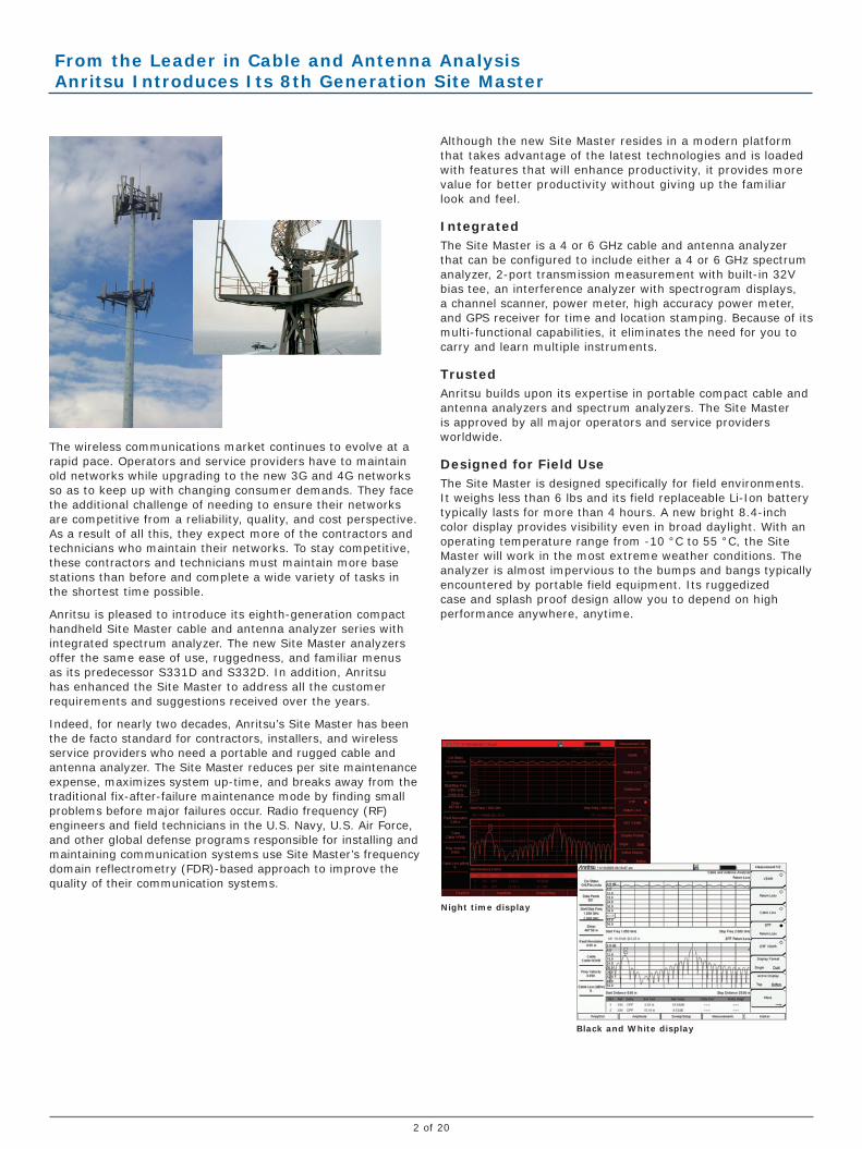
Night time display
Black and White display
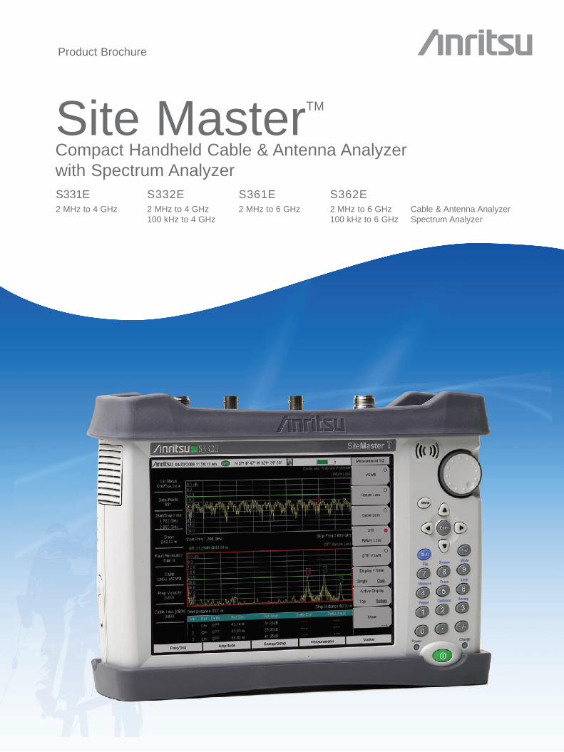
From the Leader in Cable and Antenna Analysis Anritsu Introduces Its 8th Generation Site Master
3 of 20
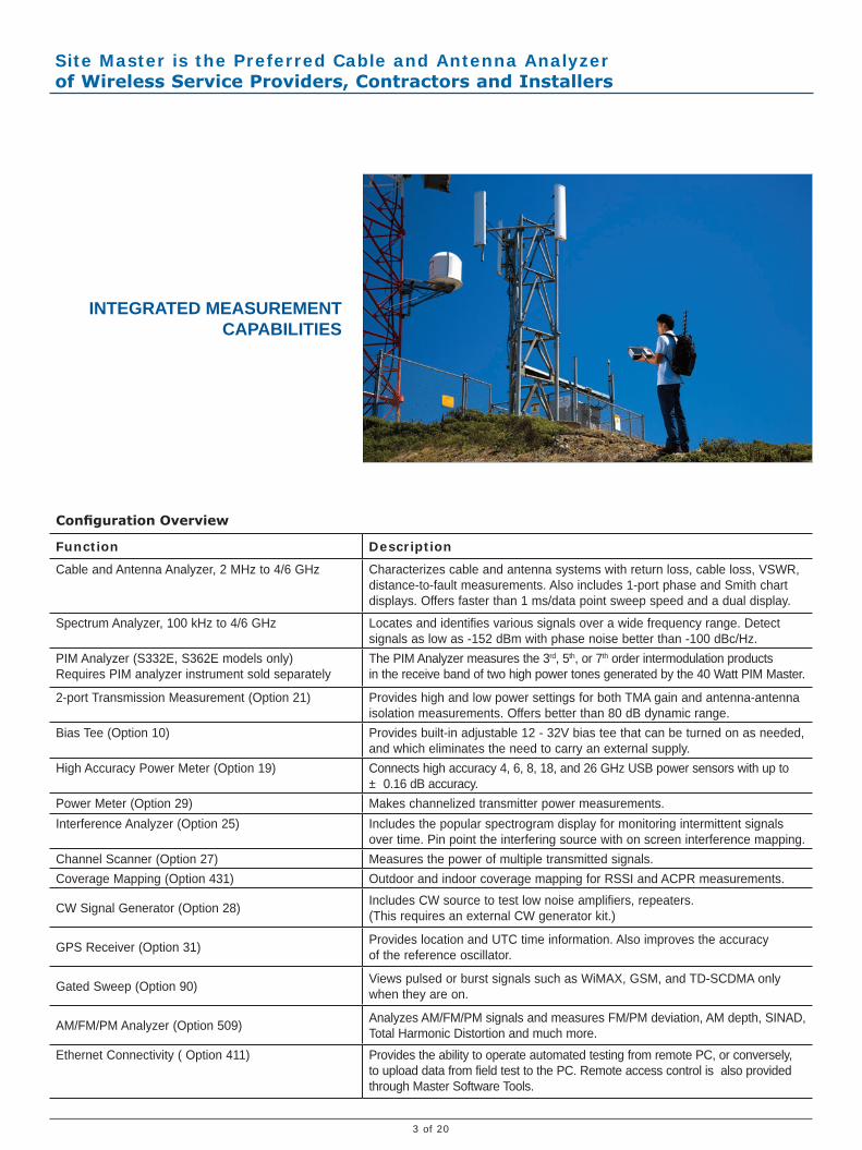
INTEGRATED MEASUREMENT CAPABILITIES
Configuration Overview
Function Description
Cable and Antenna Analyzer, 2 MHz to 4/6 GHz Characterizes cable and antenna systems with return loss, cable loss, VSWR, distance-to-fault measurements. Also includes 1-port phase and Smith chart displays. Offers faster than 1 ms/data point sweep speed and a dual display.
Spectrum Analyzer, 100 kHz to 4/6 GHz Locates and identifies various signals over a wide frequency range. Detect signals as low as -152 dBm with phase noise better than -100 dBc/Hz.
PIM Analyzer (S332E, S362E models only) Requires PIM analyzer instrument sold separately
The PIM Analyzer measures the 3rd, 5th, or 7th order intermodulation products in the receive band of two high power tones generated by the 40 Watt PIM Master.
2-port Transmission Measurement (Option 21) Provides high and low power settings for both TMA gain and antenna-antenna isolation measurements. Offers better than 80 dB dynamic range.
Bias Tee (Option 10) Provides built-in adjustable 12 - 32V bias tee that can be turned on as needed, and which eliminates the need to carry an external supply.
High Accuracy Power Meter (Option 19) Connects high accuracy 4, 6, 8, 18, and 26 GHz USB power sensors with up to ± 0.16 dB accuracy.
Power Meter (Option 29) Makes channelized transmitter power measurements. Interference Analyzer (Option 25) Includes the popular spectrogram display for monitoring intermittent signals
over time. Pin point the interfering source with on screen interference mapping.Channel Scanner (Option 27) Measures the power of multiple transmitted signals.Coverage Mapping (Option 431) Outdoor and indoor coverage mapping for RSSI and ACPR measurements.
CW Signal Generator (Option 28) Includes CW source to test low noise amplifiers, repeaters. (This requires an external CW generator kit.)
GPS Receiver (Option 31) Provides location and UTC time information. Also improves the accuracy of the reference oscillator.
Gated Sweep (Option 90) Views pulsed or burst signals such as WiMAX, GSM, and TD-SCDMA only when they are on.
AM/FM/PM Analyzer (Option 509) Analyzes AM/FM/PM signals and measures FM/PM deviation, AM depth, SINAD, Total Harmonic Distortion and much more.
Ethernet Connectivity ( Option 411) Provides the ability to operate automated testing from remote PC, or conversely, to upload data from field test to the PC. Remote access control is also provided through Master Software Tools.
Site Master is the Preferred Cable and Antenna Analyzer of Wireless Service Providers, Contractors and Installers
4 of 20
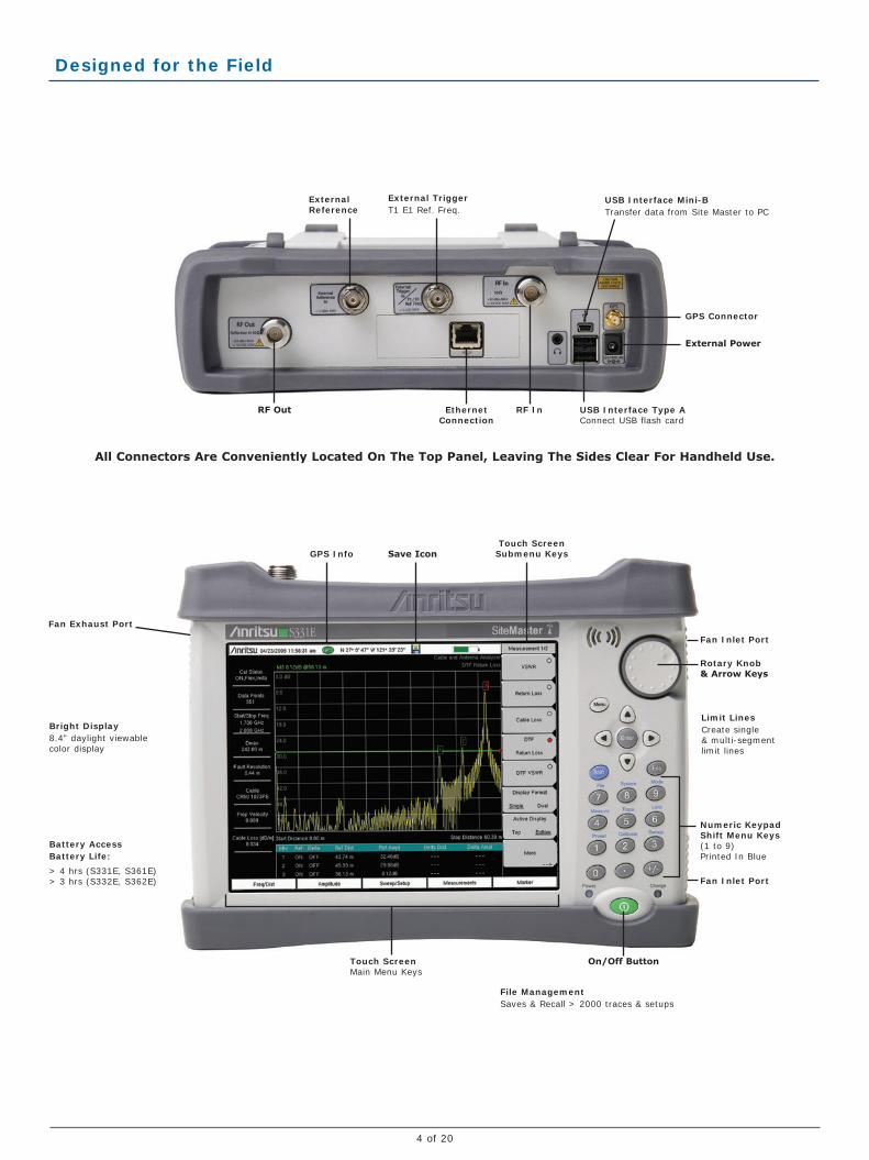
RF Out RF InEthernet Connection
External Reference
GPS Connector
External Power
Fan Inlet Port
Save IconGPS InfoTouch Screen
Submenu Keys
Fan Exhaust Port
Fan Inlet Port
Numeric Keypad Shift Menu Keys (1 to 9)Printed In Blue
Rotary Knob & Arrow Keys
On/Off Button
USB Interface Mini-BTransfer data from Site Master to PC
USB Interface Type AConnect USB flash card
File ManagementSaves & Recall > 2000 traces & setups
Limit LinesCreate single & multi-segment limit lines
External TriggerT1 E1 Ref. Freq.
Bright Display8.4” daylight viewable color display
Battery AccessBattery Life:
> 4 hrs (S331E, S361E) > 3 hrs (S332E, S362E)
Touch ScreenMain Menu Keys
All Connectors Are Conveniently Located On The Top Panel, Leaving The Sides Clear For Handheld Use.
Designed for the Field
5 of 20
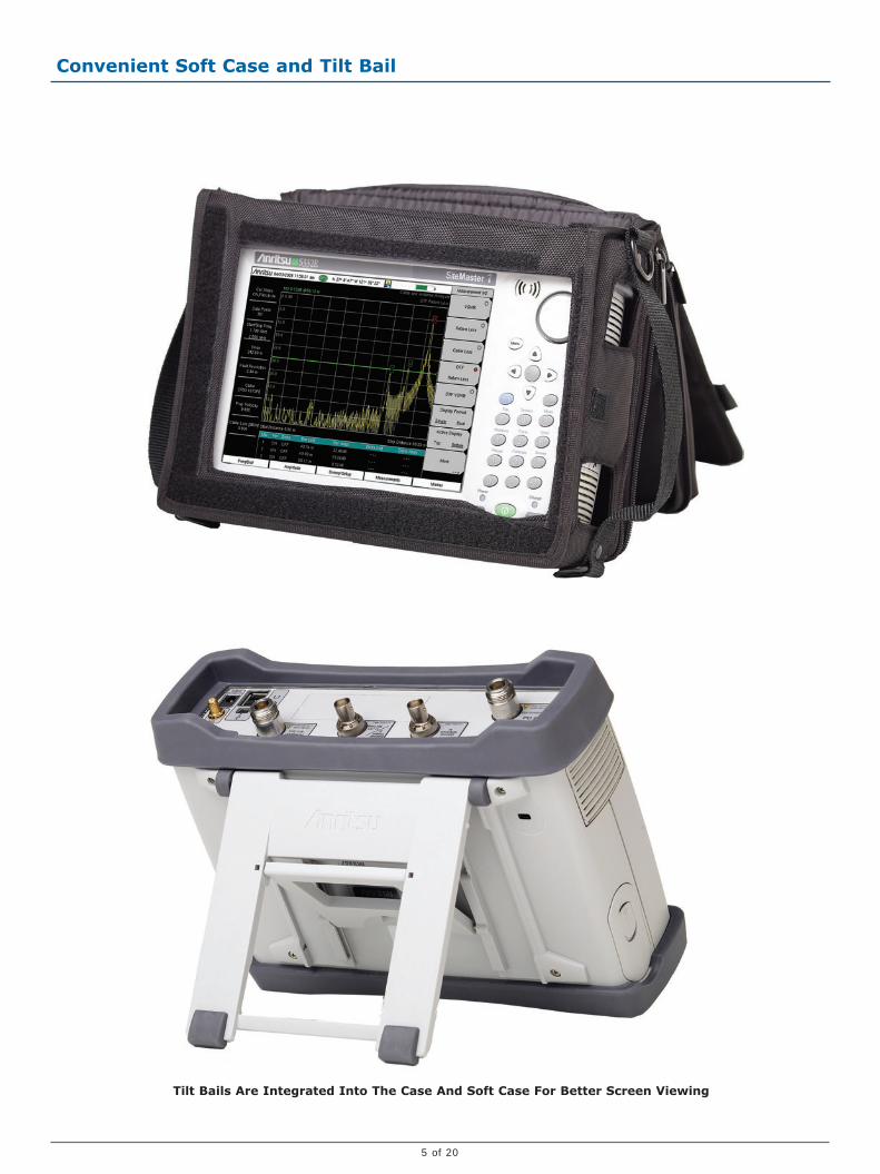
Tilt Bails Are Integrated Into The Case And Soft Case For Better Screen Viewing
Convenient Soft Case and Tilt Bail
6 of 20
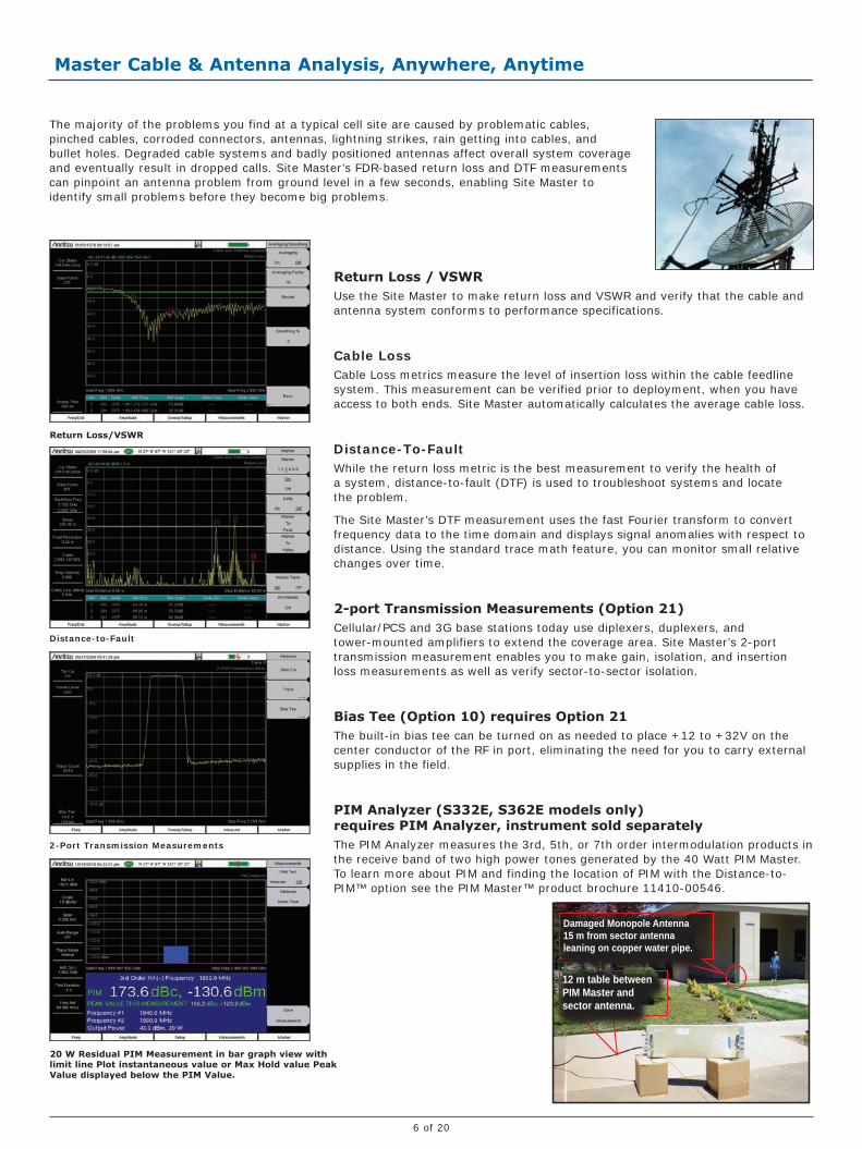
Return Loss / VSWRUse the Site Master to make return loss and VSWR and verify that the cable and antenna system conforms to performance specifications.
Cable LossCable Loss metrics measure the level of insertion loss within the cable feedline system. This measurement can be verified prior to deployment, when you have access to both ends. Site Master automatically calculates the average cable loss.
Distance-To-FaultWhile the return loss metric is the best measurement to verify the health of a system, distance-to-fault (DTF) is used to troubleshoot systems and locate the problem.
The Site Master’s DTF measurement uses the fast Fourier transform to convert frequency data to the time domain and displays signal anomalies with respect to distance. Using the standard trace math feature, you can monitor small relative changes over time.
2-port Transmission Measurements (Option 21)Cellular/PCS and 3G base stations today use diplexers, duplexers, and tower-mounted amplifiers to extend the coverage area. Site Master’s 2-port transmission measurement enables you to make gain, isolation, and insertion loss measurements as well as verify sector-to-sector isolation.
Bias Tee (Option 10) requires Option 21The built-in bias tee can be turned on as needed to place +12 to +32V on the center conductor of the RF in port, eliminating the need for you to carry external supplies in the field.
PIM Analyzer (S332E, S362E models only) requires PIM Analyzer, instrument sold separatelyThe PIM Analyzer measures the 3rd, 5th, or 7th order intermodulation products in the receive band of two high power tones generated by the 40 Watt PIM Master. To learn more about PIM and finding the location of PIM with the Distance-to-PIM™ option see the PIM Master™ product brochure 11410-00546.
The majority of the problems you find at a typical cell site are caused by problematic cables, pinched cables, corroded connectors, antennas, lightning strikes, rain getting into cables, and bullet holes. Degraded cable systems and badly positioned antennas affect overall system coverage and eventually result in dropped calls. Site Master’s FDR-based return loss and DTF measurements can pinpoint an antenna problem from ground level in a few seconds, enabling Site Master to identify small problems before they become big problems.
Distance-to-Fault
Return Loss/VSWR
2-Port Transmission Measurements
20 W Residual PIM Measurement in bar graph view with limit line Plot instantaneous value or Max Hold value Peak Value displayed below the PIM Value.
Master Cable & Antenna Analysis, Anywhere, Anytime
Damaged Monopole Antenna 15 m from sector antenna leaning on copper water pipe.
12 m table between PIM Master and sector antenna.
7 of 20
Dual DisplayThe dual display enables users to view two cable and antenna measurements on the same display. Because you can control the top and bottom displays independently, you can set markers and limit lines on each display. This results in significant time savings as there’s no need to make two measurements.
Quick Name MatrixThe integrated quick name matrix and keyboard enables you to preset up to 42 commonly used names. The quick name matrix allows you to save long file names with cell site ID, sector information, color coding, measurement type, frequency, and termination in less than five seconds. Now you can label the traces of the entire site in minutes instead of hours.
InstaCal™ CalibrationAlthough you need to get the job done as quickly as possible, you still need to make reliable and accurate measurements. Anritsu’s InstaCal module enables you to make accurate calibrations at the end of the phase stable cable without connecting a short/open/load. This calibration method can cut the calibration time by as much as 50 percent and still deliver accurate calibrations.
Standard OSL Calibration Open-Short-Load (OSL) calibration comes standard with the Site Master. All errors from source match, directivity, and frequency response are mathematically removed, allowing you to make accurate vector-corrected measurements. Directivity is usually the main contributor to measurement uncertainty, and corrected directivity of 42 dB or better is common using Anritsu’s precision components.
FlexCal™The Site Master’s FlexCal™ broadband calibration feature is an calibration method that allows you to perform a broadband calibration and change the frequency range after calibration without having to recalibrate the instrument.
RF ImmunitySite Master’s unique RF immunity algorithm solution enables you to make accurate cable and antenna measurements even in the presence of strong RF activity from co-located cell sites.
Dual Display
Quick Name Matrix
InstaCal
Cable and Antenna Analyzer Highlights - Return loss, VSWR, cable loss, DTF
- 2-port transmission measurements with 32V bias tee
- 1-port phase, Smith chart
- Quick Name Matrix reduces trace labeling time in the field
- PIM 3rd, 5th and 7th Order Frequency measurements
- Dual display mode capabilities
- Built-in, editable signal standard and cable standard lists
- Calibration: OSL Cal, FlexCal, InstaCal
- 137, 275, 551, 1102, 2204 data points
- < 1 msec per datapoint sweep speed
- Trace overlay and trace math to monitor changes with Reference traces
- Marker table with automatic peak/valley markers
- GPS tagging
- Limit lines and alarming for providing reference standards
- GPS tagging of data to verify location of tests
- Line Sweep Tools and Master Software Tools for post-analysis and report generation
Enhance Productivity with Dual Displays and Instant Calibration
8 of 20
Site Master S332E and the S362E Site Master with integrated spectrum analysis capability provide users with a high-performance, easy-to-use, feature-rich spectrum analyzer for field environments and applications requiring mobility.
Site Master’s integrated high performance spectrum analyzer makes it ideal for a broad range of activities, including spectrum monitoring, AM/FM broadcast proofing, interference analysis, field strength measurements, transmitter spectrum analysis, electro magnetic field strength, signal strength mapping, and overall field analysis of cellular 2G/3G/4G, land mobile radio, Wi-Fi, and broadcast signals.
Dynamic Range Performance
Low Level Performance
Limit Envelope
Comprehensive Marker Menu
High PerformanceThe dynamic range is better than 95 dB in 10 Hz RBW, enabling measurement of very small signals in the presence of much larger signals. The picture demonstrates the dynamic range in the Site Master
Displayed Average Noise LevelSite Master delivers impressive and best-in-class DANL performance. With the built-in pre-amp, better than -152 dBm DANL can typically be realized in 10 Hz RBW and -162 dBm when normalized to 1 Hz. This low-level performance capability is essential when looking for low-level interference signals.
GPS-Assisted Frequency AccuracyWith GPS Option 0031 the frequency accuracy is < 50 ppb. This additional accuracy is important when characterizing 3GPP signals using counted frequency markers. Also all measurements can be GPS tagged for exporting to maps.
Simple But Powerful for Field UseConvenience is a must in the field. This is why the Site Master is equipped with features that will enhance productivity in the field.
The Site Master is equipped with limit lines for all user levels. You can create single limit lines and segmented limit lines in one step using the one-button limit envelope feature.
The Site Master automatically sets the fastest sweep possible while still ensuring accurate measurements. This allows users to rely on the instrument to optimize accuracy and consistency.
Auto Attenuation ties the input attenuation to the reference level eliminating the need for the user to determine how much attenuation is needed.
Six regular and six delta markers can be displayed with a marker table that can be turned on as needed. The capability to measure noise level in terms of dBm/Hz or dBµV/Hz is a standard feature of the Site Master.
Best Performance in its Class
9 of 20
Spectrum Analyzer Highlights - Measurements: Occupied bandwidth, channel power, ACPR, C/I, AM/FM demod, field strength, emission mask
- Interference analyzer: spectrogram, signal strength, RSSI, signal ID, Interference Mapping
- Dynamic range: > 95 dB
- DANL: -162 dBm typical (normalized to 1 Hz)
- Phase noise: -100 dBc/Hz @ 10 kHz offset
- Frequency accuracy: < ± 50 ppb with GPS on
- Advanced marker functions: noise marker, frequency counter, fixed, tracking
- Advanced limit line functions: one-button envelope creation
- Detection methods: peak, RMS, negative, sample, quasi-peak
- Save-on-event: automatically saves a sweep when crossing a limit line
- Gated sweep: view pulsed or burst signals only when they are on, or off
Smart Measurements for Transmitter SystemsCommonly needed transmitter measurements are built in and can be accessed easily. These include field strength, occupied bandwidth, channel power, adjacent channel power ratio (ACPR), and emission mask.
Occupied Bandwidth
Adjacent Channel Power Ratio
Emission Mask
Occupied Bandwidth
This measurement determines the amount of spectrum used by a modulated signal. The Site Master allows you to choose between two different methods of determining bandwidth: the percent-of-power method or the “x” dB down method.
Adjacent Channel Power RatioAdjacent Channel Power Ratio is a common transmitter measurement. High ACPR will create interference for neighboring carriers. This measurement can be used to replace the traditional two-tone Intermodulation Distortion (IMD) test for system non-linear behavior.
Field Strength MeasurementsThe Site Master can determine the effects of electromagnetic fields caused by transmitter systems. Specific antenna factors of the connected antenna are automatically taken into account, and field strength is displayed directly in dBµV/m. The Site Master also supports a wide range of directional antennas. If you are using a different antenna, Master Software Tools can be used to edit the antenna list and upload the custom antenna list to the instrument to accurately measure the maximum field strength.
Emission MaskThe emission mask is a segmented upper limit line that will display frequency range, peak power and frequency, relative power and pass/fail status for each segment of the mask. The emission mask must have at least two segments. Emission mask adjusts to the peak power value of transmitted signal level per government emission mask requirements.
Master Transmitter Testing
10 of 20
Interference Analysis (Option 25)The interference analyzer option provides you with a spectrogram display, RSSI, signal strength meter, signal ID, and Interference Mapping capabilities. Site Master’s integrated spectrum analyzer can detect signals as low as -152 dBm.
Spectrogram DisplayThis option provides you with a three-dimensional display of frequency, power, and time of the spectrum activity to identify intermittent interference and track signal levels over time. The dual display screen allows for easy viewing of both the spectrum and 3D display. The Site Master allows you to save a history of data up to 72 hours.
Signal IDSite Master’s signal ID feature in the interference analyzer can help you quickly identify the type of the interfering signal. You can configure this measurement to identify all signals in the selected band or to simply monitor one single interfering frequency. The Site Master then displays results that include center frequency, signal bandwidth, and signal type (FM, GSM/GPRS/EDGE, W-CDMA/HSDPA, CDMA/EV-DO, Wi-Fi).
Carrier-To-Interference MeasurementSite Master’s carrier-to-interference measurement capability makes it simple for you to determine if the level of interference will affect users in the intended service area.
AM/FM/SSB DemodulationA built-in demodulator for AM, narrowband FM, wideband FM and single sideband allows you to easily identify the interfering signal.
Signal Strength Meter
Signal ID
Carrier-to-Interference (C/I)
As the wireless industry continues to expand, more diverse uses for the radio spectrum emerge, and the number of signals that may potentially cause interference is constantly increasing.
Compounding the problem are the many sources that can generate interference, including intentional radiators, unintentional radiators, and self interference. Interference causes Carrier-to-Interference degradation robbing the network of capacity. The goal of these measurements is to resolve interference issues as quickly as possible.
Spectrogram Display
Signal Strength MeterThe Site Master’s signal strength meter can locate an interfering signal by using a directional antenna and measuring the signal strength. It displays power in Watts or dBm, in the graphical analog meter display and by an audible beep proportional to its strength.
Master the Location of Interference
11 of 20
Interference MappingThe Interference Mapping measurement eliminates the need to use printed maps and draw lines to triangulate the interfering signal.
Using Map Master™, it is easy to convert maps and make them compatible with the Site Master. With a valid GPS signal, the instrument identifies the user location on the map. Using one of the recommended Anritsu Yagi antennas, you can identify the direction of the interfering signal and input the angle information with the rotary knob. With two or more lines from different locations, it is possible to obtain an estimate location of the interfering signal. The Interference Mapping can be done directly on the Site Master. Files can also be saved as kml and opened with Google Earth.
Directional AntennasAnritsu offers several different directional antennas covering a wide range of common frequency bands including: 822 to 900 MHz, 885 to 975 MHz, 1710 to 1880 MHz, 1850 to 1990 MHz, 2400 to 2500 MHz, 1920 to 2170 MHz, 500 to 3000 MHz, and 600 to 21000 MHz.
GPS AntennaThe 2000-1528-R GPS antenna and option (31) are required for the interference mapping and coverage mapping measurements.
Pin Point Location of Interfering Signal with Interference Mapping
Interference Mapping with Google Earth™
On Screen Interference Mapping
12 of 20
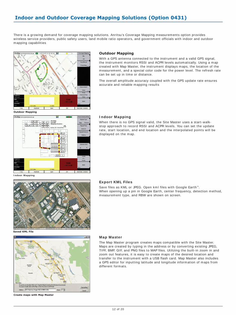
Indoor and Outdoor Coverage Mapping Solutions (Option 0431)
There is a growing demand for coverage mapping solutions. Anritsu’s Coverage Mapping measurements option provides wireless service providers, public safety users, land mobile ratio operators, and government officials with indoor and outdoor mapping capabilities
Outdoor MappingWith a GPS antenna connected to the instrument and a valid GPS signal, the instrument monitors RSSI and ACPR levels automatically. Using a map created with Map Master, the instrument displays maps, the location of the measurement, and a special color code for the power level. The refresh rate can be set up in time or distance.
The overall amplitude accuracy coupled with the GPS update rate ensures accurate and reliable mapping results
Indoor MappingWhen there is no GPS signal valid, the Site Master uses a start-walk-stop approach to record RSSI and ACPR levels. You can set the update rate, start location, and end location and the interpolated points will be displayed on the map.
Export KML FilesSave files as KML or JPEG. Open kml files with Google Earth™.
When opening up a pin in Google Earth, center frequency, detection method, measurement type, and RBW are shown on screen.
Map MasterThe Map Master program creates maps compatible with the Site Master. Maps are created by typing in the address or by converting existing JPEG, TIFF, BMP, GIF, and PNG files to MAP files. Utilizing the built-in zoom in and zoom out features, it is easy to create maps of the desired location and transfer to the instrument with a USB flash card. Map Master also includes a GPS editor for inputting latitude and longitude information of maps from different formats.
Outdoor Mapping
Indoor Mapping
Saved KML File
Create maps with Map Master
13 of 20
The Anritsu Site Master provides many different power measurements to support a wide range of applications. The high-accuracy broadband sensor family provides the best accuracy (±0.16 dB) over a wide frequency range. The power meter is ideal for users looking to making channelized measurements in a few keystrokes with minimal training. Site Master’s channel power measurement also makes channelized measurements but requires more knowledge and is recommended for more advanced users. And when you are measuring multiple channels, the channel scanner is your perfect choice.
High Accuracy Power Sensors
High Accuracy Power Meter
Power Meter
Channel Scanner
Channel PowerUse Site Master’s channel power measurement to determine the power and power density of a transmission channel. Using the built-in signal standard list, you can measure the channel power of a wide range of signals.
Power Meter (Option 29)Site Master’s internal power meter provides power measurements without any additional tools and is ideal for making channelized power measurements. You can display the results in both dBm and Watts. This option is easy to use and requires limited setup entries.
High Accuracy Power Meter (Option 19)Anritsu’s high accuracy power meter option enables you to make high accuracy RMS measurements. This capability is perfect for measuring both CW and digitally modulated signals such as CDMA/EV-DO, GSM/EDGE, WCDMA/HSPA+, and P25. You can select from a wide range of USB sensors delivering better than ±0.16 dB accuracy. An additional benefit of using the USB connection is that a separate DC supply (or battery) is not needed since the necessary power is supplied by the USB port.
- PSN50 High Accuracy RF Power Sensor, 50 MHz to 6 GHz, -30 to +20 dBm, True-RMS
- MA24105A Inline Peak Power Sensor, 350 MHz to 4 GHz, +3 to +51.76 dBm (150W), True-RMS
- MA24106A High Accuracy RF Power Sensor, 50 MHz to 6 GHz, -40 to +23 dBm, True-RMS
- MA24108A Microwave USB Power Sensor, 10 MHz to 8 GHz, -40 to +20 dBm, True-RMS
- MA24118A, Microwave USB Power Sensor, 10 MHz to 18 GHz, -40 to +20 dBm, True-RMS
- MA24126A, Microwave USB Power Sensor, 10 MHz to 26 GHz, -40 to +20 dBm, True-RMS
PC Power meterThese power sensors can be used with a PC running Microsoft Windows® via USB. They come with PowerXpert™ application, a data analysis, and control software. The application has abundant features, such as data logging, power versus time graph, big numerical display, and many more, that enable quick and accurate measurements.
Channel Scanner (Option 27)The channel scanner option measures the power of multiple transmitted signals, making it very useful for simultaneously measuring channel power of up to 20 channels in GSM, TDMA, CDMA, W-CDMA, HSDPA, and public safety networks. You can select the frequencies or the scanned data to be displayed by frequencies or the channel number. And in the custom setup menu each channel can be custom built with different frequency bandwidth, or with channels from different signal standards. With Script Master, scans can be automated for up to 1200 channels.
Power Measurements for a Wide Range of Applications
14 of 20
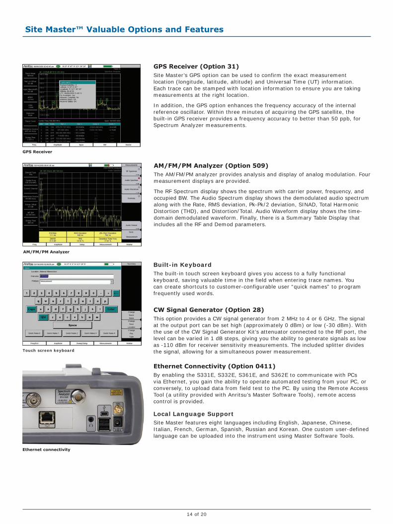
GPS Receiver (Option 31)Site Master’s GPS option can be used to confirm the exact measurement location (longitude, latitude, altitude) and Universal Time (UT) information. Each trace can be stamped with location information to ensure you are taking measurements at the right location.
In addition, the GPS option enhances the frequency accuracy of the internal reference oscillator. Within three minutes of acquiring the GPS satellite, the built-in GPS receiver provides a frequency accuracy to better than 50 ppb, for Spectrum Analyzer measurements.
GPS Receiver
AM/FM/PM Analyzer
Ethernet connectivity
Touch screen keyboard
AM/FM/PM Analyzer (Option 509)The AM/FM/PM analyzer provides analysis and display of analog modulation. Four measurement displays are provided.
The RF Spectrum display shows the spectrum with carrier power, frequency, and occupied BW. The Audio Spectrum display shows the demodulated audio spectrum along with the Rate, RMS deviation, Pk-Pk/2 deviation, SINAD, Total Harmonic Distortion (THD), and Distortion/Total. Audio Waveform display shows the time-domain demodulated waveform. Finally, there is a Summary Table Display that includes all the RF and Demod parameters.
Built-in KeyboardThe built-in touch screen keyboard gives you access to a fully functional keyboard, saving valuable time in the field when entering trace names. You can create shortcuts to customer-configurable user “quick names” to program frequently used words.
CW Signal Generator (Option 28)This option provides a CW signal generator from 2 MHz to 4 or 6 GHz. The signal at the output port can be set high (approximately 0 dBm) or low (-30 dBm). With the use of the CW Signal Generator Kit’s attenuator connected to the RF port, the level can be varied in 1 dB steps, giving you the ability to generate signals as low as -110 dBm for receiver sensitivity measurements. The included splitter divides the signal, allowing for a simultaneous power measurement.
Ethernet Connectivity (Option 0411)By enabling the S331E, S332E, S361E, and S362E to communicate with PCs via Ethernet, you gain the ability to operate automated testing from your PC, or conversely, to upload data from field test to the PC. By using the Remote Access Tool (a utility provided with Anritsu’s Master Software Tools), remote access control is provided.
Local Language SupportSite Master features eight languages including English, Japanese, Chinese, Italian, French, German, Spanish, Russian and Korean. One custom user-defined language can be uploaded into the instrument using Master Software Tools.
Site Master™ Valuable Options and Features
15 of 20
Site Master™ Valuable Options and Features
Line Sweep Tools™, Master Software Tools™ and easyTest Tools™ (for your PC)
Line Sweep FeaturesPresets
7 sets of 6 markers and 1 limit line
Next trace capability
File Types
Input: HHST DAT, VNA Measurements: Return Loss
(VSWR), Cable Loss, DTF-RL, DTF-VSWR, PIM
Output: LS DAT, VNA, CSV, PNG, BMP, JPG, PDF
Report Generator
Logo, title, company name, customer name,
location, date and time, filename, PDF, HTML,
all open traces
Tools
Cable Editor
Distance to Fault
Measurement calculator
Signal Standard Editor
Renaming Grid
Interfaces
Serial, Ethernet, USB
Capture Plots to
Screen, Database, DAT files, JPEG, Instrument
Master Software Tools FeaturesDatabase Management
Full Trace Retrieval
Trace Catalog
Group Edit
Trace Editor
Data Analysis
Trace Math and Smoothing
Data Converter
Measurement Calculator
Mapping (GPS Required)
Spectrum Analyzer Mode
Mobile WiMAX OTA Option
TS-SCDMA OTA Option
LTE, both FDD and TDD Options
Folder Spectrogram
Folder Spectrogram – 2D View
Video Folder Spectrogram – 2D View
Folder Spectrogram – 3D View
List/Parameter Editors
Traces
Antennas, Cables, Signal Standards
Product Updates
Firmware Upload
Pass/Fail
VSG Pattern Converter
Languages
Mobile WiMAX
Display
Connectivity
USB
Download measurements and live traces
Upload Lists/Parameters
Firmware Updates
Remote Access Tool over the Internet
easyTest ToolsCreate tests
Distribute procedures
Display instructions
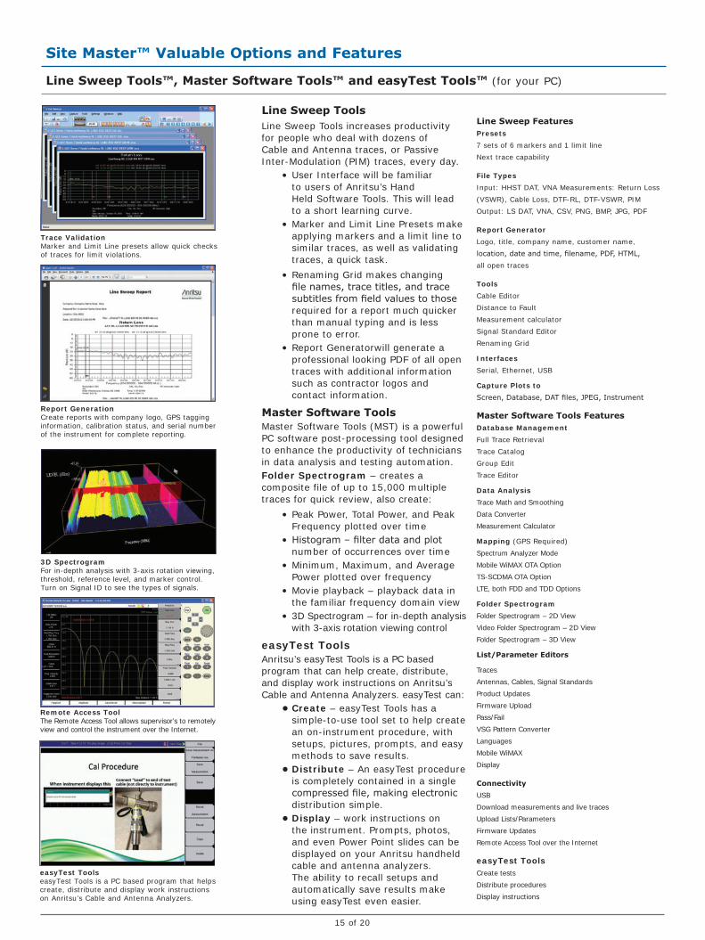
Line Sweep ToolsLine Sweep Tools increases productivity for people who deal with dozens of Cable and Antenna traces, or Passive Inter-Modulation (PIM) traces, every day.
• User Interface will be familiar to users of Anritsu’s Hand Held Software Tools. This will lead to a short learning curve.
• Marker and Limit Line Presets make applying markers and a limit line to similar traces, as well as validating traces, a quick task.
• Renaming Grid makes changing file names, trace titles, and trace subtitles from field values to those required for a report much quicker than manual typing and is less prone to error.
• Report Generatorwill generate a professional looking PDF of all open traces with additional information such as contractor logos and contact information.
Master Software ToolsMaster Software Tools (MST) is a powerful PC software post-processing tool designed to enhance the productivity of technicians in data analysis and testing automation.Folder Spectrogram – creates a composite file of up to 15,000 multiple traces for quick review, also create:
• Peak Power, Total Power, and Peak Frequency plotted over time
• Histogram – filter data and plot number of occurrences over time
• Minimum, Maximum, and Average Power plotted over frequency
• Movie playback – playback data in the familiar frequency domain view
• 3D Spectrogram – for in-depth analysis with 3-axis rotation viewing control
easyTest ToolsAnritsu’s easyTest Tools is a PC based program that can help create, distribute, and display work instructions on Anritsu’s Cable and Antenna Analyzers. easyTest can:
• Create – easyTest Tools has a simple-to-use tool set to help create an on-instrument procedure, with setups, pictures, prompts, and easy methods to save results.
• Distribute – An easyTest procedure is completely contained in a single compressed file, making electronic distribution simple.
• Display – work instructions on the instrument. Prompts, photos, and even Power Point slides can be displayed on your Anritsu handheld cable and antenna analyzers. The ability to recall setups and automatically save results make using easyTest even easier.
3D SpectrogramFor in-depth analysis with 3-axis rotation viewing, threshold, reference level, and marker control. Turn on Signal ID to see the types of signals.
easyTest ToolseasyTest Tools is a PC based program that helps create, distribute and display work instructions on Anritsu’s Cable and Antenna Analyzers.
Remote Access ToolThe Remote Access Tool allows supervisor’s to remotely view and control the instrument over the Internet.
Trace Validation Marker and Limit Line presets allow quick checks of traces for limit violations.
Report GenerationCreate reports with company logo, GPS tagging information, calibration status, and serial number of the instrument for complete reporting.

16 of 20
Site Master™ Ordering Information
Ordering Information – OptionsS331E S332E S361E S362E Description
2 MHz to 4 GHz 2 MHz to 4 GHz 2 MHz to 6 GHz 2 MHz to 6 GHz Cable and Antenna Analyzer
100 kHz to 4 GHz 100 kHz to 6 GHz Spectrum Analyzer
N/A Included N/A Included PIM Analyzer (requires PIM Master)
Options Options Options Options
S331E-0021 S332E-0021 S361E-0021 S362E-0021 2-Port Transmission Measurement
S331E-0010 S332E-0010 S361E-0010 S362E-0010 Bias-Tee (requires Option 0021 for S331E /S361E)
S331E-0031 S332E-0031 S361E-0031 S362E-0031 GPS Receiver (requires Antenna P/N 2000-1528-R)
S331E-0019 S332E-0019 S361E-0019 S362E-0019 High-Accuracy Power Meter (requires External Power Sensor)
S332E-0029 S362E-0029 Power Meter
S332E-0025 S362E-0025 Interference Analyzer (Option 0031 recommended)
S332E-0027 S362E-0027 Channel Scanner
S332E-0431 S362E-0431 Coverage Mapping (requires Option 0031)
S332E-0090 S362E-0090 Gated Sweep
S332E-0028 S362E-0028 C/W Signal Generator (requires CW Signal Generator Kit, P/N 69793)
S332E-0509 S362E-0509 AM/FM/PM Analyzer
S331E-0411 S332E-0411 S361E-0411 S362E-0411 Ethernet Connectivity
S331E-0098 S332E-0098 S361E-0098 S362E-0098 Standard Calibration (ANSI 2540-1-1994)
S331E-0099 S332E-0099 S361E-0099 S362E-0099 Premium Calibration to Z540 plus test data
Power Sensors (For complete ordering information see the respective datasheets of each sensor)Model Number Description
PSN50 High Accuracy RF Power Sensor, 50 MHz to 6 GHz, +20 dBm
MA24105A Inline Peak Power Sensor, 350 MHz to 4 GHz, +51.76 dBm
MA24106A High Accuracy RF Power Sensor, 50 MHz to 6 GHz, +23 dBm
MA24108A Microwave USB Power Sensor, 10 MHz to 8 GHz, +20 dBm
MA24118A Microwave USB Power Sensor, 10 MHz to 18 GHz, +20 dBm
MA24126A Microwave USB Power Sensor, 10 MHz to 26 GHz, +20 dBm
Manuals (soft copy included on Handheld Instruments Documentation Disc and at www.anritsu.com)Part Number Description
10920-00060 Handheld Instruments Documentation Disc
10580-00252 Site Master User Guide (Hard copy included)
10580-00241 Cable and Antenna Analyzer Measurement Guide
10580-00242 2-Port Transmission Measurement - Bias-Tee
10580-00244
Spectrum Analyzer Measurement Guide - Interference Analyzer, Channel Scanner, Gated Sweep,
CW Signal Generator, AM/FM/PM Analyzer, Interference Mapping, Coverage Mapping
10580-00240 Power Meter Measurement Guide - High Accuracy Power Meter
10580-00256 Programming Manual
10580-00280 PIM Master User Guide
Troubleshooting Guides (soft copy at www.anritsu.com)Part Number Description
11410-00473 Cable, Antenna and Components
11410-00551 Spectrum Analyzers
11410-00472 Interference
17 of 20
Site Master™ Ordering Information
Standard Accessories (included with instrument)
Part Number Description
10920-00060 Handheld Instruments Documentation Disc
10580-00252 Site Master User Guide
3-68736 Soft Carrying Case
2300-498 Master Software Tools (MST) CD Disc
2300-530 Anritsu Tool Box with Line Sweep Tools (LST) DVD Disc
633-44 Rechargeable Li-Ion Battery
40-168-R AC-DC Adapter
806-141-R Automotive Cigarette Lighter 12 VDC Adapter
3-2000-1498 USB A/5-pin mini-B Cable, 10 feet/305 cm
11410-00484
Site Master™ S331E, S332E, S361E, S362E Technical Data SheetOne Year Warranty (Including battery, firmware, and software) Certificate of Calibration and Conformance
Optional Accessories
Calibration Components, 50 Ω
Part Number Description
ICN50B InstaCal™ Calibration Module, 38 dB, 2 MHz to 6.0 GHz, N(m), 50 Ω
OSLN50-1 Precision Open/Short/Load, N(m), 42 dB, 6.0 GHz, 50 Ω
OSLNF50-1 Precision Open/Short/Load, N(f), 42 dB, 6.0 GHz, 50 Ω
2000-1618-R Precision Open/Short/Load, 7/16 DIN(m), DC to 6.0 GHz 50 Ω
2000-1619-R Precision Open/Short/Load, 7/16 DIN(f), DC to 6.0 GHz 50 Ω
22N50 Open/Short, N(m), DC to 18 GHz, 50 Ω
22NF50 Open/Short, N(f), DC to 18 GHz, 50 Ω
SM/PL-1 Precision Load, N(m), 42 dB, 6.0 GHz, 50 Ω
SM/PLNF-1 Precision Load, N(f), 42 dB, 6.0 GHz, 50 Ω
Calibration Components, 75 Ω
Part Number Description
22N75 Open/Short, N(m), DC to 3 GHz, 75 Ω
22NF75 Open/Short, N(f), DC to 3 GHz, 75 Ω
26N75A Precision Termination, N(m), DC to 3 GHz, 75 Ω
26NF75A Precision Termination, N(f), DC to 3 GHz, 75 Ω
12N50-75B Matching Pad, DC to 3 GHz, 50 Ω to 75 Ω
Phase-Stable Test Port Cables, Armored w/ Reinforced Grip (recommended for cable & antenna line sweep applications)
Part Number Description
15RNFN50-1.5-R 1.5 m, DC to 6 GHz, N(m) to N(f), 50 Ω
15RDFN50-1.5-R 1.5 m, DC to 6 GHz, N(m) to 7/16 DIN(f), 50 Ω
15RDN50-1.5-R 1.5 m, DC to 6 GHz, N(m) to 7/16 DIN(m), 50 Ω
15RNFN50-3.0-R 3.0 m, DC to 6 GHz, N(m) to N(f), 50 Ω
15RDFN50-3.0-R 3.0 m, DC to 6 GHz, N(m) to 7/16 DIN(f), 50 Ω
15RDN50-3.0-R 3.0 m, DC to 6 GHz, N(m) to 7/16 DIN(m), 50 Ω
InterChangeable Adaptor Phase Stable Test Port Cables, Armored w/Reinforced Grip (recommended for cable and antenna line sweep applications. It uses the same ruggedized grip as the Reinforced grip series cables. Now you can also change the adaptor interface on the grip to four different connector types)
Part Number Description
15RCN50-1.5-R 1.5 m, DC to 6 GHz, N(m), N(f), 7/16 DIN(m), 7/16 DIN(f), 50 Ω
15RCN50-3.0-R 3.0 m, DC to 6 GHz, N(m), N(f), 7/16 DIN(m), 7/16 DIN(f), 50 Ω
Phase-Stable Test Port Cables, Armored (recommended for use with tightly spaced connectors and other general purpose applications)
Part Number Description
15NNF50-1.5C 1.5 m, DC to 6 GHz, N(m) to N(f), 50 Ω
15NN50-1.5C 1.5 m, DC to 6 GHz, N(m) to N(m), 50 Ω
15NDF50-1.5C 1.5 m, DC to 6 GHz, N(m) to 7/16 DIN(f), 50 Ω
15ND50-1.5C 1.5 m, DC to 6 GHz, N(m) to 7/16 DIN(m), 50 Ω
15NNF50-3.0C 3.0 m, DC to 6 GHz, N(m) to N(f), 50 Ω
15NN50-3.0C 3.0 m, DC to 6 GHz, N(m) to N(m), 50 Ω
18 of 20
Site Master™ Ordering Information
Optional Accessories (continued)
Adapters
Part Number Description
1091-26-R SMA(m) to N(m), DC to 18 GHz, 50 Ω
1091-27-R SMA(f) to N(m), DC to 18 GHz, 50 Ω
1091-80-R SMA(m) to N(f), DC to 18 GHz, 50 Ω
1091-81-R SMA(f) to N(f), DC to 18 GHz, 50 Ω
1091-172-R BNC(f) to N(m), DC to 1.3 GHz, 50 Ω
510-90 7/16 DIN(f) to N(m), DC to 7.5 GHz, 50 Ω
510-91 7/16 DIN(f) to N(f), DC to 7.5 GHz, 50 Ω
510-92 7/16 DIN(m) to N(m), DC to 7.5 GHz, 50 Ω
510-93 7/16 DIN(m) to N(f), DC to 7.5 GHz, 50 Ω
510-96 7/16 DIN(m) to 7/16 DIN (m), DC to 7.5 GHz, 50 Ω
510-97 7/16 DIN(f) to 7/16 DIN (f), DC to 7.5 GHz, 50 Ω
1091-379-R 7/16 DIN(f) to 7/16 DIN(f), DC to 6 GHz, 50 Ω, w/ Reinforced Grip
510-102-R N(m) to N(m), DC to 11 GHz, 50 Ω, 90 degrees right angle
Precision Adapters
Part Number Description
34NN50A Precision Adapter, N(m) to N(m), DC to 18 GHz, 50 Ω
34NFNF50 Precision Adapter, N(f) to N(f), DC to 18 GHz, 50 Ω
Miscellaneous Accessories
Part Number Description
2000-1528-R GPS Antenna, SMA(m) with 15 ft cable
2000-1652-R GPS Antenna, SMA(m) with 1 ft cable
69793 CW Signal Generator Kit
2000-1520-R USB Flash Drive
2000-1374 External Charger for Li-lon Batteries
2000-1371-R Ethernet Cable, 7 ft/213 cm
3-806-152 Cat 5e Crossover Patch Cable, 7 ft/213 cm)
2300-517 Phase Noise Measurement Software (requires Ethernet Option 0411)
2300-532 Map Master CD
Backpack and Transit Case
Part Number Description
67135 Anritsu Backpack (For Handheld Instrument and PC)
760-243-R Large Transit Case with Wheels and Handle
Directional Antennas
Part Number Description
2000-1411-R 822 MHz to 900 MHz, N(f), 10 dBd, Yagi
2000-1412-R 885 MHz to 975 MHz, N(f), 10 dBd, Yagi
2000-1413-R 1710 MHz to 1880 MHz, N(f), 10 dBd. Yagi
2000-1414-R 1850 MHz to 1990 MHz, N(f), 9.3 dBd, Yagi
2000-1415-R 2400 MHz to 2500 MHz, N(f), 10 dBd, Yagi
2000-1416-R 1920 MHz to 2170 MHz, N(f), 10 dBd, Yagi
2000-1519-R 500 MHz to 3 GHz, log periodic
19 of 20
Site Master™ Ordering Information
Optional Accessories (continued)
Portable Antennas
Part Number Description
2000-1200-R 806 MHz to 866 MHz, SMA(m), 50 Ω
2000-1473-R 870 MHz to 960 MHz, SMA(m), 50 Ω
2000-1035-R 896 MHz to 941 MHz, SMA(m), 50 Ω (1/2 wave)
2000-1030-R 1710 MHz to 1880 MHz, SMA(m), 50 Ω (1/2 wave)
2000-1474-R 1710 MHz to 1880 MHz with knuckle elbow (1/2 wave)
2000-1031-R 1850 MHz to 1990 MHz, SMA(m), 50 Ω (1/2 wave)
2000-1475-R 1920 MHz to 1980 MHz and 2110 MHz to 2170 MHz, SMA(m), 50 Ω
2000-1032-R 2400 MHz to 2500 MHz, SMA(m), 50 Ω (1/2 wave)
2000-1361-R 2400 MHz to 2500 MHz, 5000 MHz to 6000 MHz, SMA(m), 50 Ω
2000-1636-R Antenna Kit (Consists of: 2000-1030-R, 2000-1031-R, 2000-1032-R, 2000-1200-R, 2000-1035-R, 2000-1361-R, and carrying pouch)
Mag Mount Broadband Antenna
Part Number Description
2000-1647-R Cable 1: 698-1200 MHz 2 dBi peak gain, 1700-2700 MHz 5 dBi peak gain, N(m), 50 Ω, 10 ftCable 2: 3000-6000 MHz 5 dBi peak gain, N(m), 50 Ω, 10 ftCable 3: GPS 26 db gain, SMA(m), 50 Ω, 10 ft
2000-1645-R 694-894 MHz 3 dBi peak gain, 1700-2700 MHz 3dBi peak gain, N(m), 50 Ω, 10 ft
2000-1646-R 750-1250 MHz 3 dBi peak gain, 1650-2000 MHz 5 dBi peak gain, 2100-2700 MHz 3 dBi peak gain, N(m), 50 Ω, 10 ft
2000-1648-R 1700-6000 MHz 3 dBi peak gain, N(m), 50 Ω, 10 ft
Filters
Part Number Description
1030-114-R 806 MHz to 869 MHz, N(m) to SMA(f), 50 Ω
1030-109-R 824 MHz to 849 MHz, N(m) to SMA(f), 50 Ω
1030-110-R 880 MHz to 915 MHz, N(m) to SMA(f), 50 Ω
1030-105-R 890 MHz to 915 MHz Band, 0.41 dB loss, N(m) to SMA(f), 50 Ω
1030-111-R 1850 MHz to 1910 MHz, N(m) to SMA(f), 50 Ω
1030-106-R 1710 MHz to 1790 MHz Band, 0.34 dB loss, N(m) to SMA(f), 50 Ω
1030-107-R 1910 MHz to 1990 MHz Band, 0.41 dB loss, N(m) to SMA(f), 50 Ω
1030-112-R 2400 MHz to 2484 MHz, N(m) to SMA(f), 50 Ω
1030-149-R High Pass, 150 MHz, N(m) to N(f), 50 Ω
1030-150-R High Pass, 400 MHz, N(m) to N(f), 50 Ω
1030-151-R High Pass, 700 MHz, N(m) to N(f), 50 Ω
1030-152-R Low Pass, 200 MHz, N(m) to N(f), 50 Ω
1030-153-R Low Pass, 550 MHz, N(m) to N(f), 50 Ω
1030-155-R 2500 MHz to 2700 MHz, N(m) to N(f), 50 Ω
Attenuators
Part Number Description
3-1010-122 20 dB, 5 W, DC to 12.4 GHz, N(m) to N(f)
42N50-20 20 dB, 5 W, DC to 18 GHz, N(m) to N(f)
42N50A-30 30 dB, 50 W, DC to 18 GHz, N(m) to N(f)
3-1010-123 30 dB, 50 W, DC to 8.5 GHz, N(m) to N(f)
1010-127-R 30 dB, 150 W, DC to 3 GHz, N(m) to N(f)
3-1010-124 40 dB, 100 W, DC to 8.5 GHz, N(m) to N(f), Uni-directional
1010-121 40 dB, 100 W, DC to 18 GHz, N(m) to N(f), Uni-directional
1010-128-R 40 dB, 150 W, DC to 3 GHz, N(m) to N(f)
® Anritsu All trademarks and registered trademarks are the property of their respective owners. Data subject to change without notice. For the most recent specifications visit: www.anritsu.com
The Master Users Group is an organization dedicated to providing training, technical support, networking opportunities and links to Master product development teams. As a member you will receive the Insite Quarterly Newsletter with user stories, measurement tips, new product news and more.Visit us to register today: www.anritsu.com/MUG
To receive a quote to purchase a product or order accessories visit our online ordering site: www.ShopAnritsu.com
Training at AnritsuAnritsu has designed courses to help you stay up to date with technologies important to your job.For available training courses visit: www.anritsu.com/training
Please Contact:
Anritsu prints on recycled paper with vegetable soybean oil ink.
11410-00516, Rev. E Printed in United States 2012-06©2012 Anritsu Company. All Rights Reserved.
• United States Anritsu Company1155 East Collins Boulevard, Suite 100, Richardson, TX, 75081 U.S.A. Toll Free: 1-800-ANRITSU (267-4878) Phone: +1-972-644-1777 Fax: +1-972-671-1877• Canada Anritsu Electronics Ltd.700 Silver Seven Road, Suite 120, Kanata, Ontario K2V 1C3, Canada Phone: +1-613-591-2003 Fax: +1-613-591-1006
• Brazil Anritsu Electrônica Ltda.Praça Amadeu Amaral, 27 - 1 Andar 01327-010 - Bela Vista - São Paulo - SP - Brazil Phone: +55-11-3283-2511 Fax: +55-11-3288-6940
• Mexico Anritsu Company, S.A. de C.V.Av. Ejército Nacional No. 579 Piso 9, Col. Granada 11520 México, D.F., México Phone: +52-55-1101-2370 Fax: +52-55-5254-3147
• United Kingdom Anritsu EMEA Ltd.200 Capability Green, Luton, Bedfordshire LU1 3LU, U.K. Phone: +44-1582-433280 Fax: +44-1582-731303
• France Anritsu S.A.12 avenue du Québec, Batiment Iris 1-Silic 612, 91140 VILLEBON SUR YVETTE, France Phone: +33-1-60-92-15-50 Fax: +33-1-64-46-10-65
• Germany Anritsu GmbHNemetschek Haus, Konrad-Zuse-Platz 1 81829 München, Germany Phone: +49 (0) 89 442308-0 Fax: +49 (0) 89 442308-55
• Italy Anritsu S.r.l.Via Elio Vittorini 129 00144 Roma Italy Phone: +39-06-509-9711 Fax: +39-06-502-2425
• Sweden Anritsu ABBorgafjordsgatan 13A, 164 40 KISTA, Sweden Phone: +46-8-534-707-00 Fax: +46-8-534-707-30
• Finland Anritsu ABTeknobulevardi 3-5, FI-01530 Vantaa, Finland Phone: +358-20-741-8100 Fax: +358-20-741-8111
• Denmark Anritsu A/S (for Service Assurance) Anritsu AB (for Test & Measurement)Kay Fiskers Plads 9, 2300 Copenhagen S, Denmark Phone: +45-7211-2200 Fax: +45-7211-2210
• RussiaAnritsu EMEA Ltd. Representation Office in RussiaTverskaya str. 16/2, bld. 1, 7th floor. Russia, 125009, Moscow Phone: +7-495-363-1694 Fax: +7-495-935-8962
• United Arab Emirates Anritsu EMEA Ltd. Dubai Liaison OfficeP O Box 500413 - Dubai Internet City Al Thuraya Building, Tower 1, Suite 701, 7th Floor Dubai, United Arab Emirates Phone: +971-4-3670352 Fax: +971-4-3688460
• Singapore Anritsu Pte. Ltd.60 Alexandra Terrace, #02-08, The Comtech (Lobby A) Singapore 118502 Phone: +65-6282-2400 Fax: +65-6282-2533
• India Anritsu Pte. Ltd. India Branch Office2nd & 3rd Floor, #837/1, Binnamangla 1st Stage, Indiranagar, 100ft Road, Bangalore - 560038, India Phone: +91-80-4058-1300 Fax: +91-80-4058-1301
• P. R. China (Shanghai) Anritsu (China) Co., Ltd.Room 1715, Tower A CITY CENTER of Shanghai, No. 100 Zunyi Road, Chang Ning District, Shanghai 200051, P.R. China Phone: +86-21-6237-0898 Fax: +86-21-6237-0899
• P. R. China (Hong Kong) Anritsu Company Ltd.Unit 1006-7, 10/F., Greenfield Tower, Concordia Plaza, No. 1 Science Museum Road, Tsim Sha Tsui East, Kowloon, Hong Kong, P. R. China Phone: +852-2301-4980 Fax: +852-2301-3545
• Japan Anritsu Corporation8-5, Tamura-cho, Atsugi-shi, Kanagawa, 243-0016 Japan Phone: +81-46-296-1221 Fax: +81-46-296-1238
• Korea Anritsu Corporation, Ltd.502, 5FL H-Square N B/D, 681, Sampyeong-dong, Bundang-gu, Seongnam-si, Gyeonggi-do, 463-400 Korea Phone: +82-31-696-7750 Fax: +82-31-696-7751
• Australia Anritsu Pty Ltd.Unit 21/270 Ferntree Gully Road, Notting Hill, Victoria 3168, Australia Phone: +61-3-9558-8177 Fax: +61-3-9558-8255
• Taiwan Anritsu Company Inc.7F, No. 316, Sec. 1, Neihu Rd., Taipei 114, Taiwan Phone: +886-2-8751-1816 Fax: +886-2-8751-1817