Embed Size (px)
Citation preview
Technical Data Sheet
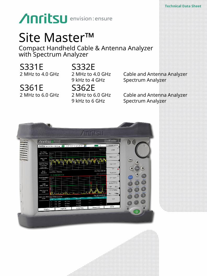
Site Master™Compact Handheld Cable & Antenna Analyzer with Spectrum Analyzer
S331E2 MHz to 4.0 GHz
S332E2 MHz to 4.0 GHz9 kHz to 4 GHz
Cable and Antenna AnalyzerSpectrum Analyzer
S361E2 MHz to 6.0 GHz
S362E2 MHz to 6.0 GHz9 kHz to 6 GHz
Cable and Antenna AnalyzerSpectrum Analyzer
S331E, S332E, S361E, S362E Specifications
2 of 24 PN: 11410-00484 Rev. V S331E, S332E, S361E, S362E TDS
Introduction Anritsu introduces its eighth generation compact handheld Cable and Antenna Analyzers with Spectrum Analyzers for installation and maintenance of wireless networks. They feature the highest performance and the most capabilities ever offered by Anritsu in a compact handheld tester since introducing its first line sweeper in 1995.
Cable and Antenna Analyzer Highlights
Spectrum and Interference Analyzer Highlights
Capabilities and Functional Highlights
• Measurements: RL, VSWR, Cable Loss, DTF, Phase• 2-port Transmission Measurement: High/Low Power• Sweep Speed: 1 ms/data point, typical
• Display: Single or Dual Measurement Touchscreen• Calibration: OSL, InstaCal™, and FlexCal™• Bias Tee: 32 V internal
• Measurements: Occupied Bandwidth, Channel Power, ACPR, C/I
• Interference Analyzer: Spectrogram, Signal Strength, RSSI, Signal ID, Interference Mapping
• Dynamic Range: > 95 dB in 10 Hz RBW• DANL: –152 dBm in 10 Hz RBW• Phase Noise: –100 dBc/Hz max @ 10 kHz offset at 1 GHz• Frequency Accuracy: < ± 50 ppb with GPS On
• AM / FM / PM Analyzer• CPRI LTE RF Measurements• OBSAI LTE RF Measurements• LTE/LTE-A FDD/TDD; MIMO (2x2, 4x4)• EMF Test (S332E & S362E)• High Accuracy Power Meter• Up to 50 GHz USB Sensors• PIM Alert Application (S332E & S362E)• Master Software Tools™• Line Sweep Tools™• easyTest Tools™• USB & Optional Ethernet (Option 413) for data transfer and
instrument control
• Handheld Interference Hunter support (S332E & S362E)• On-Screen Interference Mapping• On-Screen Coverage Mapping• GPS tagging of saved traces• Increase throughput by automating repetitive or operator
intensive tasks via Ethernet or USB. Remote programming provided via Ethernet (Option 413)
• 4.5 hour battery operation time• Store 2000 Traces internally• Touchscreen keyboard• Quick Name Matrix • < 5 minute warm-up time• E-Learning Training• Certified Line Sweep Training
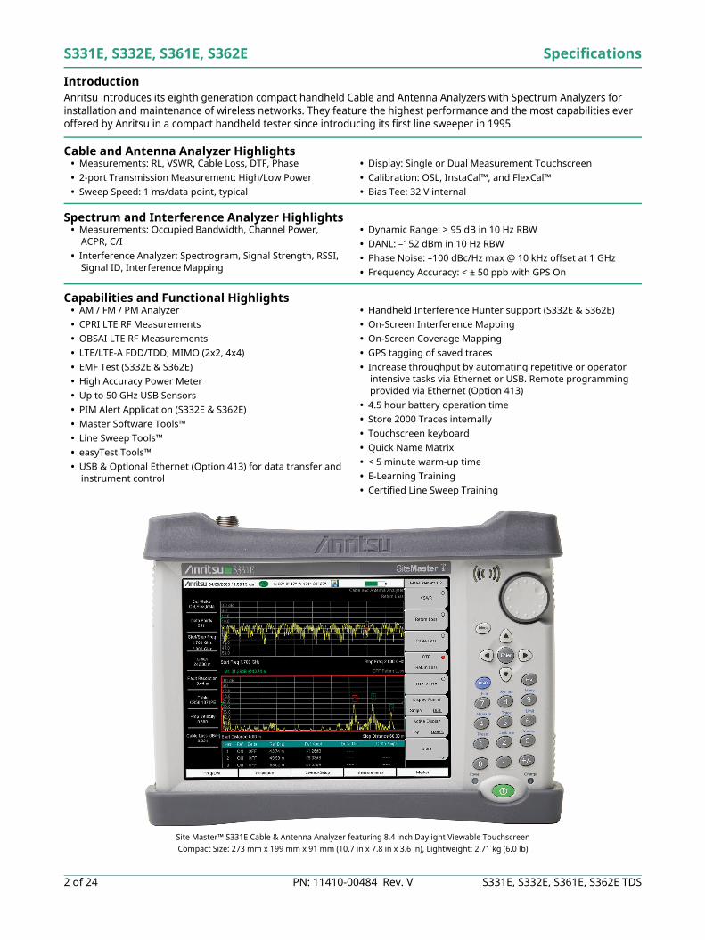
Site Master™ S331E Cable & Antenna Analyzer featuring 8.4 inch Daylight Viewable TouchscreenCompact Size: 273 mm x 199 mm x 91 mm (10.7 in x 7.8 in x 3.6 in), Lightweight: 2.71 kg (6.0 lb)
Specifications S331E, S332E, S361E, S362E
S331E, S332E, S361E, S362E TDS PN: 11410-00484 Rev. V 3 of 24
Table of Contents
Definitions. . . . . . . . . . . . . . . . . . . . . . . . . . . . . . . . . . . . . . . . . . . . . . . . . . . . . . . . . . . . . . . . . . . . . . . . . . . . . . . . . . . . . 3Cable and Antenna Analyzer . . . . . . . . . . . . . . . . . . . . . . . . . . . . . . . . . . . . . . . . . . . . . . . . . . . . . . . . . . . . . . . . . . . . . 42-Port Transmission Measurement (Option 21) . . . . . . . . . . . . . . . . . . . . . . . . . . . . . . . . . . . . . . . . . . . . . . . . . . . . . 5Bias-Tee (Option 10) . . . . . . . . . . . . . . . . . . . . . . . . . . . . . . . . . . . . . . . . . . . . . . . . . . . . . . . . . . . . . . . . . . . . . . . . . . . . 5Spectrum Analyzer . . . . . . . . . . . . . . . . . . . . . . . . . . . . . . . . . . . . . . . . . . . . . . . . . . . . . . . . . . . . . . . . . . . . . . . . . . . . . 6Coverage Mapping (Option 431) . . . . . . . . . . . . . . . . . . . . . . . . . . . . . . . . . . . . . . . . . . . . . . . . . . . . . . . . . . . . . . . . . . 8Interference Analyzer (Option 25). . . . . . . . . . . . . . . . . . . . . . . . . . . . . . . . . . . . . . . . . . . . . . . . . . . . . . . . . . . . . . . . . 8GPS Receiver (Option 31) . . . . . . . . . . . . . . . . . . . . . . . . . . . . . . . . . . . . . . . . . . . . . . . . . . . . . . . . . . . . . . . . . . . . . . . . 8Channel Scanner (Option 27) . . . . . . . . . . . . . . . . . . . . . . . . . . . . . . . . . . . . . . . . . . . . . . . . . . . . . . . . . . . . . . . . . . . . . 8CW Signal Generator (Option 28) . . . . . . . . . . . . . . . . . . . . . . . . . . . . . . . . . . . . . . . . . . . . . . . . . . . . . . . . . . . . . . . . . 9Gated Sweep (Option 90) . . . . . . . . . . . . . . . . . . . . . . . . . . . . . . . . . . . . . . . . . . . . . . . . . . . . . . . . . . . . . . . . . . . . . . . . 9Electromagnetic Field Test (Option 444) . . . . . . . . . . . . . . . . . . . . . . . . . . . . . . . . . . . . . . . . . . . . . . . . . . . . . . . . . . . 9Ethernet Connectivity (Option 413). . . . . . . . . . . . . . . . . . . . . . . . . . . . . . . . . . . . . . . . . . . . . . . . . . . . . . . . . . . . . . . . 9Power Meter . . . . . . . . . . . . . . . . . . . . . . . . . . . . . . . . . . . . . . . . . . . . . . . . . . . . . . . . . . . . . . . . . . . . . . . . . . . . . . . . . .10High Accuracy Power Meter (Option 19) . . . . . . . . . . . . . . . . . . . . . . . . . . . . . . . . . . . . . . . . . . . . . . . . . . . . . . . . . .10RF over Fiber Hardware (Option 759) . . . . . . . . . . . . . . . . . . . . . . . . . . . . . . . . . . . . . . . . . . . . . . . . . . . . . . . . . . . . .10CPRI LTE RF Measurements (Option 752) . . . . . . . . . . . . . . . . . . . . . . . . . . . . . . . . . . . . . . . . . . . . . . . . . . . . . . . . .11OBSAI LTE RF Measurements (Option 753) . . . . . . . . . . . . . . . . . . . . . . . . . . . . . . . . . . . . . . . . . . . . . . . . . . . . . . . .13AM/FM/PM Signal Analyzers (Option 509) . . . . . . . . . . . . . . . . . . . . . . . . . . . . . . . . . . . . . . . . . . . . . . . . . . . . . . . . .14General Specifications . . . . . . . . . . . . . . . . . . . . . . . . . . . . . . . . . . . . . . . . . . . . . . . . . . . . . . . . . . . . . . . . . . . . . . . . .15Line Sweep Tools . . . . . . . . . . . . . . . . . . . . . . . . . . . . . . . . . . . . . . . . . . . . . . . . . . . . . . . . . . . . . . . . . . . . . . . . . . . . . .16easyTest Tools . . . . . . . . . . . . . . . . . . . . . . . . . . . . . . . . . . . . . . . . . . . . . . . . . . . . . . . . . . . . . . . . . . . . . . . . . . . . . . . .16Master Software Tools . . . . . . . . . . . . . . . . . . . . . . . . . . . . . . . . . . . . . . . . . . . . . . . . . . . . . . . . . . . . . . . . . . . . . . . . .17Web Remote Control. . . . . . . . . . . . . . . . . . . . . . . . . . . . . . . . . . . . . . . . . . . . . . . . . . . . . . . . . . . . . . . . . . . . . . . . . . .17Programmable Remote Control . . . . . . . . . . . . . . . . . . . . . . . . . . . . . . . . . . . . . . . . . . . . . . . . . . . . . . . . . . . . . . . . .17Ordering Information – Options . . . . . . . . . . . . . . . . . . . . . . . . . . . . . . . . . . . . . . . . . . . . . . . . . . . . . . . . . . . . . . . . .18Standard Accessories . . . . . . . . . . . . . . . . . . . . . . . . . . . . . . . . . . . . . . . . . . . . . . . . . . . . . . . . . . . . . . . . . . . . . . . . . .19Power Sensors . . . . . . . . . . . . . . . . . . . . . . . . . . . . . . . . . . . . . . . . . . . . . . . . . . . . . . . . . . . . . . . . . . . . . . . . . . . . . . . .19Manuals. . . . . . . . . . . . . . . . . . . . . . . . . . . . . . . . . . . . . . . . . . . . . . . . . . . . . . . . . . . . . . . . . . . . . . . . . . . . . . . . . . . . . .19Trouble Shooting Guides . . . . . . . . . . . . . . . . . . . . . . . . . . . . . . . . . . . . . . . . . . . . . . . . . . . . . . . . . . . . . . . . . . . . . . .19Optional Accessories. . . . . . . . . . . . . . . . . . . . . . . . . . . . . . . . . . . . . . . . . . . . . . . . . . . . . . . . . . . . . . . . . . . . . . . . . . .20
Definitions Specifications All specifications and characteristics apply to Revision 1 instruments under the following conditions, unless otherwise stated: • After 5 minutes of warm-up time, where the instrument is left in the ON state• Sweep mode set to Performance• When using the internal reference signal
Typical Performance Typical performance is the measured performance of an average unit and is not warranted.Calibration Cycle Calibration is within the recommended 12 month period.
All specifications subject to change without notice. For the most current data sheet, please visit the Anritsu web site: www.anritsu.com
S331E, S332E, S361E, S362E Specifications
4 of 24 PN: 11410-00484 Rev. V S331E, S332E, S361E, S362E TDS
Cable and Antenna Analyzer
Measurements Measurements VSWR
Return LossCable LossDistance-to-Fault (DTF) Return LossDistance-to-Fault (DTF) VSWR1-Port PhaseSmith Chart (50/75 Ω selectable)
Setup Parameters Measurement Display Single/Dual Measurement Display with independent markers
Frequency Start/Stop, Signal Standard, Start CalDTF Start/Stop, DTF Aid, Units (m/ft), Cable Loss, Propagation Velocity, Cable, Windowing
Windowing Rectangular, Normal Side Lobe, Low Side Lobe, Minimum Side LobeAmplitude Top, Bottom Auto Scale, Full Scale
Sweep Run/Hold, Single/Continuous, RF Immunity (High/Low), Data Points, Averaging/Smoothing, Output Power (High/Low), RF Pwr When Hold (On/Off)
Data Points 137, 275, 551, 1102, 2204Markers Markers 1-6 (On/Off), Delta Makers 1-6 (On/Off), Marker to Peak/Valley, Peak/Valley Auto,
Marker Table (On/Off), All Markers OffTraces Recall, Copy to Display Memory, No Trace Math, Trace ± Memory, Trace Overlay (On/Off)
Limit Line On/Off, Single Limit, Multi-segment Edit, Limit Alarm (On/Off), Pass Fail Message (On/Off), Pass/Fail (Unbounded/Bounded), Warning Limit Offset, Clear Limit
Calibration Start Cal, Cal Type (Standard/FlexCal), Disp Valid Cal Temp RangeSave/Recall Setups, Measurements (.vna, .dat), Screen Shots (.jpg) (save only)
Application Options Bias-Tee (On/Off), Impedance (50 Ω, 75 Ω, Other)
Frequency Frequency Range 2 MHz to 4 GHz (S331E, S332E), 2 MHz to 6 GHz (S361E, S362E)
Frequency Accuracy ≤ ± 2.5 ppm @ 25 ºCFrequency Resolution 1 kHz (RF immunity low), 100 kHz (RF immunity high)
Output Power High 0 dBm, typicalLow –30 dBm, typical
Interference Immunity On-Channel +17 dBm @ > 1.0 MHz from carrier frequency
On-Frequency 0 dBm within ± 10 kHz of the carrier frequency
Measurement Speed Return Loss ≤ 1.00 ms/data point, RF immunity low, typical
Distance-to-Fault ≤ 1.25 ms/data point, RF immunity low, typical
Return Loss Measurement Range 0 dB to 60 dB
Resolution 0.01 dB
VSWR Measurement Range 1:1 to 65:1
Resolution 0.01
Cable Loss Measurement Range 0 dB to 30 dB
Resolution 0.01 dB
Distance-to-Fault Vertical Range Return Loss 0 dB to 60 dB
Vertical Range VSWR 1:1 to 65:1Fault Resolution (meters) (1.5 x 10⁸ x vp) / ΔF (vp = velocity propagation constant, ΔF is F2–F1 in Hz)
Horizontal Range (meters) 0 to (Data Points–1) x Fault Resolution, to a maximum of 1500 meters (4921 ft)
1-Port Phase Measurement Range –180º to +180º
Resolution 0.01º
Smith Chart Resolution 0.01 50/75 ohm selectable
Specifications S331E, S332E, S361E, S362E
S331E, S332E, S361E, S362E TDS PN: 11410-00484 Rev. V 5 of 24
Cable and Antenna Analyzer (continued)
Measurement Accuracy CorrectedDirectivity > 42 dB, OSL Calibration
> 38 dB, InstaCal™ Calibration
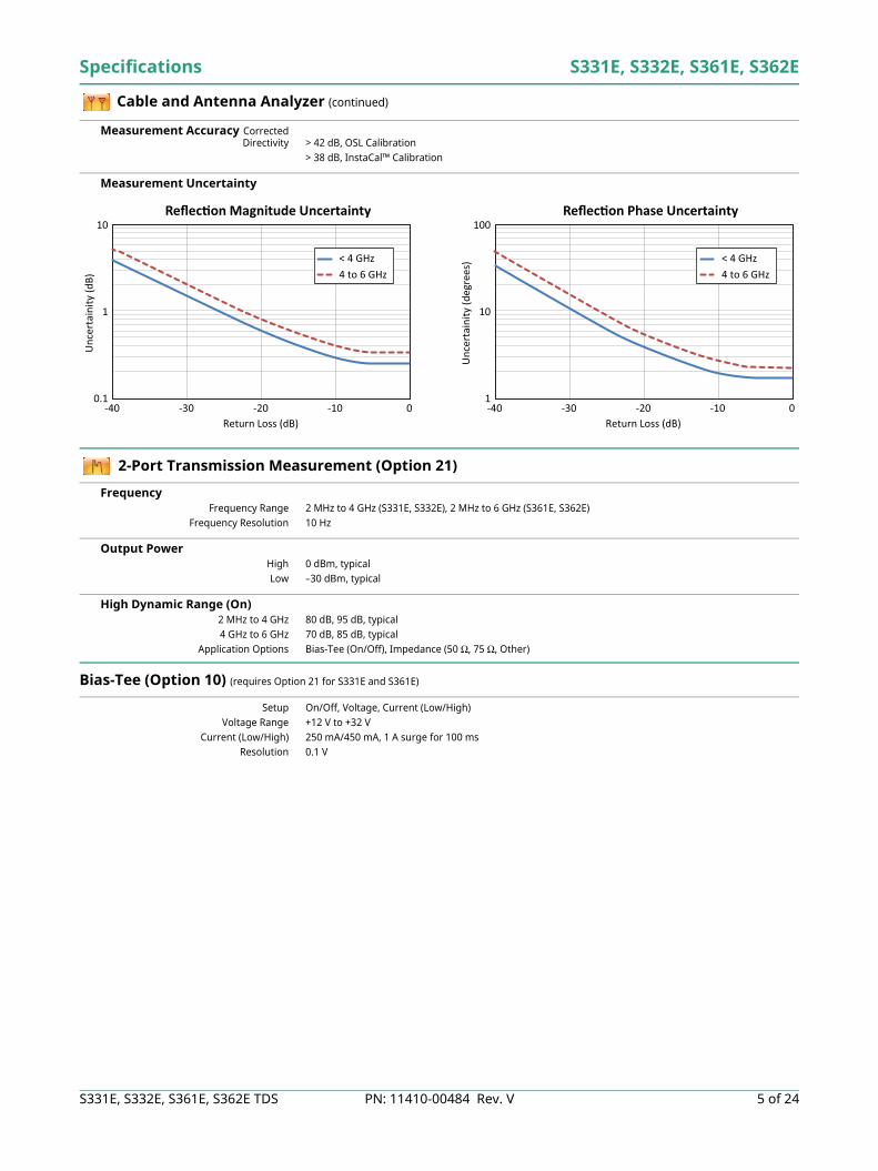
Measurement Uncertainty
2-Port Transmission Measurement (Option 21)
Frequency Frequency Range 2 MHz to 4 GHz (S331E, S332E), 2 MHz to 6 GHz (S361E, S362E)
Frequency Resolution 10 Hz
Output Power High 0 dBm, typicalLow –30 dBm, typical
High Dynamic Range (On) 2 MHz to 4 GHz 80 dB, 95 dB, typical4 GHz to 6 GHz 70 dB, 85 dB, typical
Application Options Bias-Tee (On/Off), Impedance (50 Ω, 75 Ω, Other)
Bias-Tee (Option 10) (requires Option 21 for S331E and S361E)
Setup On/Off, Voltage, Current (Low/High)Voltage Range +12 V to +32 V
Current (Low/High) 250 mA/450 mA, 1 A surge for 100 msResolution 0.1 V
10
1
0.1-40 -30 -20
Return Loss (dB)
Unc
erta
inity
(dB)
-10 0
Re ec on Magnitude Uncertainty
< 4 GHz4 to 6 GHz
100
10
1-40 -30 -20
Return Loss (dB)
Unc
erta
inity
(deg
rees
)
-10 0
Re ec on Phase Uncertainty
< 4 GHz4 to 6 GHz
S331E, S332E, S361E, S362E Specifications
6 of 24 PN: 11410-00484 Rev. V S331E, S332E, S361E, S362E TDS
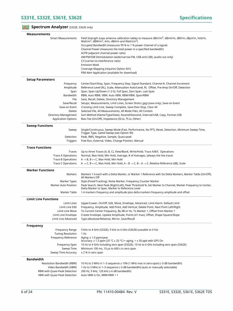
Spectrum Analyzer (S332E, S362E only)
Measurements Smart Measurements Field Strength (uses antenna calibration tables to measure dBm/m2, dBmV/m, dBV/m, dBμV/m, Volt/m,
Watt/m2, dBW/m2, A/m, dBA/m and Watt/cm2)Occupied Bandwidth (measures 99 % to 1 % power channel of a signal)Channel Power (measures the total power in a specified bandwidth)ACPR (adjacent channel power ratio)AM/FM/SSB Demodulation (wide/narrow FM, USB and LSB), (audio out only)C/I (carrier-to-interference ratio)Emission MaskCoverage Mapping (requires Option 431)PIM Alert Application (available for download)
Setup Parameters Frequency Center/Start/Stop, Span, Frequency Step, Signal Standard, Channel #, Channel IncrementAmplitude Reference Level (RL), Scale, Attenuation Auto/Level, RL Offset, Pre-Amp On/Off, Detection
Span Span, Span Up/Down (1-2-5), Full Span, Zero Span, Last SpanBandwidth RBW, Auto RBW, VBW, Auto VBW, RBW/VBW, Span/RBW
File Save, Recall, Delete, Directory ManagementSave/Recall Setups, Measurements, Limit Lines, Screen Shots (.jpg) (save only), Save-on-Event
Save-on-Event Crossing Limit Line, Sweep Complete, Save-then-Stop, Clear AllDelete Selected File, All Measurements, All Mode Files, All Content
Directory Management Sort Method (Name/Type/Date), Ascend/Descend, Internal/USB, Copy, Format USBApplication Options Bias-Tee (On/Off), Impedance (50 Ω, 75 Ω, Other)
Sweep Functions Sweep Single/Continuous, Sweep Mode (Fast, Performance, No FFT), Reset, Detection, Minimum Sweep Time,
Trigger Type, Gated Sweep (see Option 90)Detection Peak, RMS, Negative, Sample, Quasi-peak
Triggers Free Run, External, Video, Change Position, Manual
Trace Functions Traces Up to three Traces (A, B, C), View/Blank, Write/Hold, Trace A/B/C Operations
Trace A Operations Normal, Max Hold, Min Hold, Average, # of Averages, (always the live trace)Trace B Operations A → B, B ↔ C, Max Hold, Min HoldTrace C Operations A → C, B ↔ C, Max Hold, Min Hold, A – B → C, B – A → C, Relative Reference (dB), Scale
Marker Functions Markers Markers 1-6 each with a Delta Marker, or Marker 1 Reference with Six Delta Markers, Marker Table (On/Off),
All Markers OffMarker Types Style (Fixed/Tracking), Noise Marker, Frequency Counter Marker
Marker Auto-Position Peak Search, Next Peak (Right/Left), Peak Threshold %, Set Marker to Channel, Marker Frequency to Center, Delta Marker to Span, Marker to Reference Level
Marker Table 1-6 markers frequency and amplitude plus delta markers frequency amplitude and offset
Limit Line Functions Limit Lines Upper/Lower, On/Off, Edit, Move, Envelope, Advanced, Limit Alarm, Default Limit
Limit Line Edit Frequency, Amplitude, Add Point, Add Vertical, Delete Point, Next Point Left/RightLimit Line Move To Current Center Frequency, By dB or Hz, To Marker 1, Offset from Marker 1
Limit Line Envelope Create Envelope, Update Amplitude, Points (41 max), Offset, Shape Square/SlopeLimit Line Advanced Type (Absolute/Relative), Mirror, Save/Recall
Frequency Frequency Range 9 kHz to 4 GHz (S332E), 9 kHz to 6 GHz (S362E) (useable to 0 Hz)
Tuning Resolution 1 HzFrequency Reference Aging: ± 1.0 ppm/year
Accuracy: ± 1.5 ppm (25 °C ± 25 °C) + aging, < ± 50 ppb with GPS OnFrequency Span 10 Hz to 4 GHz including zero span (S332E), 10 Hz to 6 GHz including zero span (S362E)
Sweep Time Minimum 100 ms, 10 µs to 600 s in zero spanSweep Time Accuracy ± 2 % in zero span
Bandwidth Resolution Bandwidth (RBW) 10 Hz to 3 MHz in 1–3 sequence ± 10% (1 MHz max in zero-span) (–3 dB bandwidth)
Video Bandwidth (VBW) 1 Hz to 3 MHz in 1–3 sequence (–3 dB bandwidth) (auto or manually selectable)RBW with Quasi-Peak Detection 200 Hz, 9 kHz, 120 kHz (–6 dB bandwidth)VBW with Quasi-Peak Detection Auto VBW is On, RBW/VBW = 1
Specifications S331E, S332E, S361E, S362E
S331E, S332E, S361E, S362E TDS PN: 11410-00484 Rev. V 7 of 24
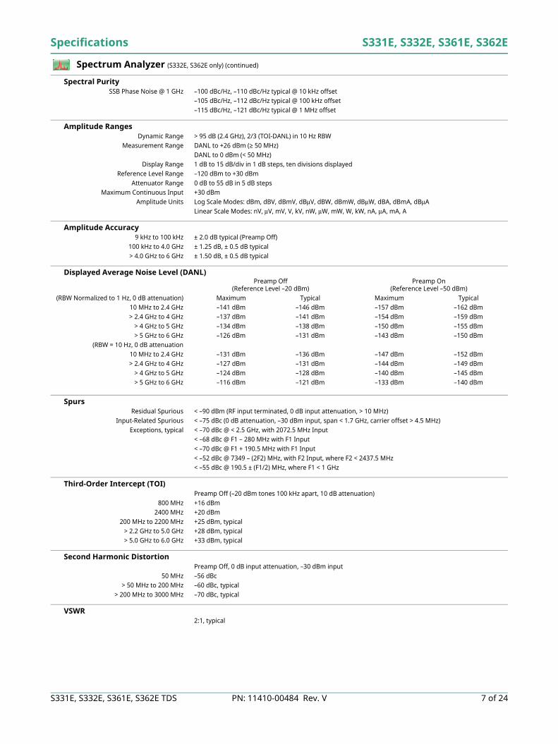
Spectrum Analyzer (S332E, S362E only) (continued)
Spectral Purity SSB Phase Noise @ 1 GHz –100 dBc/Hz, –110 dBc/Hz typical @ 10 kHz offset
–105 dBc/Hz, –112 dBc/Hz typical @ 100 kHz offset–115 dBc/Hz, –121 dBc/Hz typical @ 1 MHz offset
Amplitude Ranges Dynamic Range > 95 dB (2.4 GHz), 2/3 (TOI-DANL) in 10 Hz RBW
Measurement Range DANL to +26 dBm (≥ 50 MHz)DANL to 0 dBm (< 50 MHz)
Display Range 1 dB to 15 dB/div in 1 dB steps, ten divisions displayedReference Level Range –120 dBm to +30 dBm
Attenuator Range 0 dB to 55 dB in 5 dB stepsMaximum Continuous Input +30 dBm
Amplitude Units Log Scale Modes: dBm, dBV, dBmV, dBμV, dBW, dBmW, dBμW, dBA, dBmA, dBμALinear Scale Modes: nV, μV, mV, V, kV, nW, μW, mW, W, kW, nA, μA, mA, A
Amplitude Accuracy 9 kHz to 100 kHz ± 2.0 dB typical (Preamp Off)
100 kHz to 4.0 GHz ± 1.25 dB, ± 0.5 dB typical> 4.0 GHz to 6 GHz ± 1.50 dB, ± 0.5 dB typical
Displayed Average Noise Level (DANL)
Spurs Residual Spurious < –90 dBm (RF input terminated, 0 dB input attenuation, > 10 MHz)
Input-Related Spurious < –75 dBc (0 dB attenuation, –30 dBm input, span < 1.7 GHz, carrier offset > 4.5 MHz)Exceptions, typical < –70 dBc @ < 2.5 GHz, with 2072.5 MHz Input
< –68 dBc @ F1 – 280 MHz with F1 Input< –70 dBc @ F1 + 190.5 MHz with F1 Input< –52 dBc @ 7349 – (2F2) MHz, with F2 Input, where F2 < 2437.5 MHz< –55 dBc @ 190.5 ± (F1/2) MHz, where F1 < 1 GHz
Third-Order Intercept (TOI) Preamp Off (–20 dBm tones 100 kHz apart, 10 dB attenuation)
800 MHz +16 dBm2400 MHz +20 dBm
200 MHz to 2200 MHz +25 dBm, typical> 2.2 GHz to 5.0 GHz +28 dBm, typical> 5.0 GHz to 6.0 GHz +33 dBm, typical
Second Harmonic Distortion Preamp Off, 0 dB input attenuation, –30 dBm input
50 MHz –56 dBc> 50 MHz to 200 MHz –60 dBc, typical
> 200 MHz to 3000 MHz –70 dBc, typical
VSWR 2:1, typical
Preamp Off(Reference Level –20 dBm)
Preamp On(Reference Level –50 dBm)
(RBW Normalized to 1 Hz, 0 dB attenuation) Maximum Typical Maximum Typical10 MHz to 2.4 GHz –141 dBm –146 dBm –157 dBm –162 dBm> 2.4 GHz to 4 GHz –137 dBm –141 dBm –154 dBm –159 dBm
> 4 GHz to 5 GHz –134 dBm –138 dBm –150 dBm –155 dBm> 5 GHz to 6 GHz –126 dBm –131 dBm –143 dBm –150 dBm
(RBW = 10 Hz, 0 dB attenuation10 MHz to 2.4 GHz –131 dBm –136 dBm –147 dBm –152 dBm> 2.4 GHz to 4 GHz –127 dBm –131 dBm –144 dBm –149 dBm
> 4 GHz to 5 GHz –124 dBm –128 dBm –140 dBm –145 dBm> 5 GHz to 6 GHz –116 dBm –121 dBm –133 dBm –140 dBm
S331E, S332E, S361E, S362E Specifications
8 of 24 PN: 11410-00484 Rev. V S331E, S332E, S361E, S362E TDS
Coverage Mapping (Option 431) (S332E, S362E only; requires Option 31 GPS)
Measurements Indoor Mapping RSSI, ACPR
Outdoor Mapping RSSI, ACPR
Setup Parameters Frequency Center/Start/Stop, Span, Freq Step, Signal Standard, Channel #, Channel IncrementAmplitude Reference Level (RL), Scale, Attenuation Auto/Level, RL Offset, Pre-Amp On/Off, Detection
Span Span, Span Up/Down (1-2-5), Full Span, Zero Span, Last SpanBW RBW, Auto RBW, VBW, Auto VBW, RBW/VBW, Span/VBW
Measurement Setup ACPR, RSSIPoint Distance / Time Setup Repeat Type Time Distance
Save Points Map Save KML, JPEG, Tab DelimitedRecall Points Map Recall Map, Recall KML Points only, Recall KML Points with Map, Recall Default Grid
Interference Analyzer (Option 25) (S332E, S362E only)
Measurements Spectrum Field Strength
Occupied BandwidthChannel PowerAdjacent Channel Power Ratio (ACPR)AM/FM/SSB Demodulation (Wide/Narrow FM, Upper/Lower SSB), (audio out only)Carrier-to-Interference ratio (C/I)
Spectrogram Collect data up to 72 hoursSignal Strength Gives visual and aural indication of signal strength
Received Signal Strength Indicator (RSSI) Collect data up to one weekGives visual and aural indication of signal strength
Signal ID (up to 12 signals) Center FrequencyBandwidthSignal Type (FM, GSM, W-CDMA, CDMA, Wi-Fi)Closest Channel NumberNumber of Carriers
Signal-to-Noise Ratio (SNR) > 10 dBInterference Mapping Triangulate location of interference with on-display maps
Application Options Bias-Tee (On/Off), Impedance (50 Ω, 75 Ω, Other)Support for MA2700A Handheld Interference Hunter
GPS Receiver (Option 31) (antenna sold separately)
Setup On/Off, Antenna Voltage 3.3/5.0 V, GPS InfoGPS Time/Location Indicator Time, Latitude, Longitude and Altitude on display
Time, Latitude, Longitude and Altitude with trace storageHigh Frequency Accuracy Spectrum Analyzer, Interference Analyzer, CW Signal Analyzers
< ± 50 ppb with GPS On, GPS antenna connected, 3 minutes after satellite lock in selected modeConnector SMA, Female
Channel Scanner (Option 27) (S332E, S362E only)
Number of Channels 1 to 20 ChannelsMeasurements Graph/Table, Max Hold (On/5 s/Off), Freq/Channel, Current/Max, Single/Dual Color
Scanner Scan Channels, Scan Frequencies, Scan Customer List, Scan Script Master™Amplitude Reference Level, Scale
Custom Scan Signal Standard, Channel, # of Channels, Channel Step Size, Custom ScanFrequency Range 9 kHz to 4 GHz (S332E), 9 kHz to 6 GHz (S362E)
Frequency Accuracy ± 10 Hz + Time base errorMeasurement Range –110 dBm to +26 dBm
Application Options Bias-Tee (On/Off), Impedance (50 Ω, 75 Ω, Other)
Specifications S331E, S332E, S361E, S362E
S331E, S332E, S361E, S362E TDS PN: 11410-00484 Rev. V 9 of 24
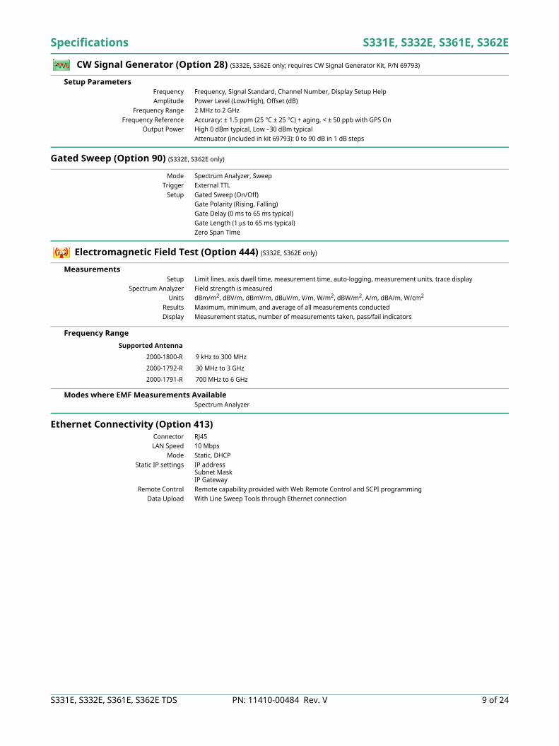
CW Signal Generator (Option 28) (S332E, S362E only; requires CW Signal Generator Kit, P/N 69793)
Setup Parameters Frequency Frequency, Signal Standard, Channel Number, Display Setup HelpAmplitude Power Level (Low/High), Offset (dB)
Frequency Range 2 MHz to 2 GHzFrequency Reference Accuracy: ± 1.5 ppm (25 °C ± 25 °C) + aging, < ± 50 ppb with GPS On
Output Power High 0 dBm typical, Low –30 dBm typicalAttenuator (included in kit 69793): 0 to 90 dB in 1 dB steps
Gated Sweep (Option 90) (S332E, S362E only)
Mode Spectrum Analyzer, SweepTrigger External TTL
Setup Gated Sweep (On/Off)Gate Polarity (Rising, Falling)Gate Delay (0 ms to 65 ms typical)Gate Length (1 μs to 65 ms typical)Zero Span Time
Electromagnetic Field Test (Option 444) (S332E, S362E only)
Measurements Setup Limit lines, axis dwell time, measurement time, auto-logging, measurement units, trace display
Spectrum Analyzer Field strength is measuredUnits dBm/m2, dBV/m, dBmV/m, dBuV/m, V/m, W/m2, dBW/m2, A/m, dBA/m, W/cm2
Results Maximum, minimum, and average of all measurements conductedDisplay Measurement status, number of measurements taken, pass/fail indicators
Frequency Range
Modes where EMF Measurements Available Spectrum Analyzer
Ethernet Connectivity (Option 413) Connector RJ45LAN Speed 10 Mbps
Mode Static, DHCPStatic IP settings IP address
Subnet MaskIP Gateway
Remote Control Remote capability provided with Web Remote Control and SCPI programmingData Upload With Line Sweep Tools through Ethernet connection
Supported Antenna
2000-1800-R 9 kHz to 300 MHz
2000-1792-R 30 MHz to 3 GHz
2000-1791-R 700 MHz to 6 GHz
S331E, S332E, S361E, S362E Specifications
10 of 24 PN: 11410-00484 Rev. V S331E, S332E, S361E, S362E TDS
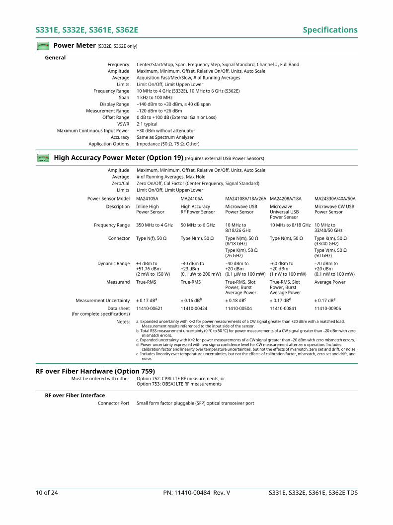
Power Meter (S332E, S362E only)
General Frequency Center/Start/Stop, Span, Frequency Step, Signal Standard, Channel #, Full BandAmplitude Maximum, Minimum, Offset, Relative On/Off, Units, Auto Scale
Average Acquisition Fast/Med/Slow, # of Running AveragesLimits Limit On/Off, Limit Upper/Lower
Frequency Range 10 MHz to 4 GHz (S332E), 10 MHz to 6 GHz (S362E)Span 1 kHz to 100 MHz
Display Range –140 dBm to +30 dBm, ≤ 40 dB spanMeasurement Range –120 dBm to +26 dBm
Offset Range 0 dB to +100 dB (External Gain or Loss)VSWR 2:1 typical
Maximum Continuous Input Power +30 dBm without attenuatorAccuracy Same as Spectrum Analyzer
Application Options Impedance (50 Ω, 75 Ω, Other)
High Accuracy Power Meter (Option 19) (requires external USB Power Sensors)
Amplitude Maximum, Minimum, Offset, Relative On/Off, Units, Auto ScaleAverage # of Running Averages, Max HoldZero/Cal Zero On/Off, Cal Factor (Center Frequency, Signal Standard)
Limits Limit On/Off, Limit Upper/Lower
RF over Fiber Hardware (Option 759) Must be ordered with either Option 752: CPRI LTE RF measurements, or
Option 753: OBSAI LTE RF measurements
RF over Fiber Interface Connector Port Small form factor pluggable (SFP) optical transceiver port
Power Sensor Model MA24105A MA24106A MA24108A/18A/26A MA24208A/18A MA24330A/40A/50A
Description Inline High Power Sensor
High Accuracy RF Power Sensor
Microwave USB Power Sensor
Microwave Universal USB Power Sensor
Microwave CW USB Power Sensor
Frequency Range 350 MHz to 4 GHz 50 MHz to 6 GHz 10 MHz to 8/18/26 GHz
10 MHz to 8/18 GHz 10 MHz to 33/40/50 GHz
Connector Type N(f), 50 Ω Type N(m), 50 Ω Type N(m), 50 Ω(8/18 GHz)Type K(m), 50 Ω(26 GHz)
Type N(m), 50 Ω Type K(m), 50 Ω(33/40 GHz)Type V(m), 50 Ω(50 GHz)
Dynamic Range +3 dBm to +51.76 dBm(2 mW to 150 W)
–40 dBm to +23 dBm(0.1 µW to 200 mW)
–40 dBm to +20 dBm(0.1 µW to 100 mW)
–60 dBm to +20 dBm(1 nW to 100 mW)
–70 dBm to +20 dBm(0.1 nW to 100 mW)
Measurand True-RMS True-RMS True-RMS, Slot Power, Burst Average Power
True-RMS, Slot Power, Burst Average Power
Average Power
Measurement Uncertainty ± 0.17 dBa ± 0.16 dBb ± 0.18 dBc ± 0.17 dBd ± 0.17 dBe
Data sheet(for complete specifications)
11410-00621 11410-00424 11410-00504 11410-00841 11410-00906
Notes: a. Expanded uncertainty with K=2 for power measurements of a CW signal greater than +20 dBm with a matched load. Measurement results referenced to the input side of the sensor.
b. Total RSS measurement uncertainty (0 ºC to 50 ºC) for power measurements of a CW signal greater than –20 dBm with zero mismatch errors.
c. Expanded uncertainty with K=2 for power measurements of a CW signal greater than –20 dBm with zero mismatch errors.d. Power uncertainty expressed with two sigma confidence level for CW measurement after zero operation. Includes
calibration factor and linearity over temperature uncertainties, but not the effects of mismatch, zero set and drift, or noise.e. Includes linearity over temperature uncertainties, but not the effects of calibration factor, mismatch, zero set and drift, and
noise.
Specifications S331E, S332E, S361E, S362E
S331E, S332E, S361E, S362E TDS PN: 11410-00484 Rev. V 11 of 24
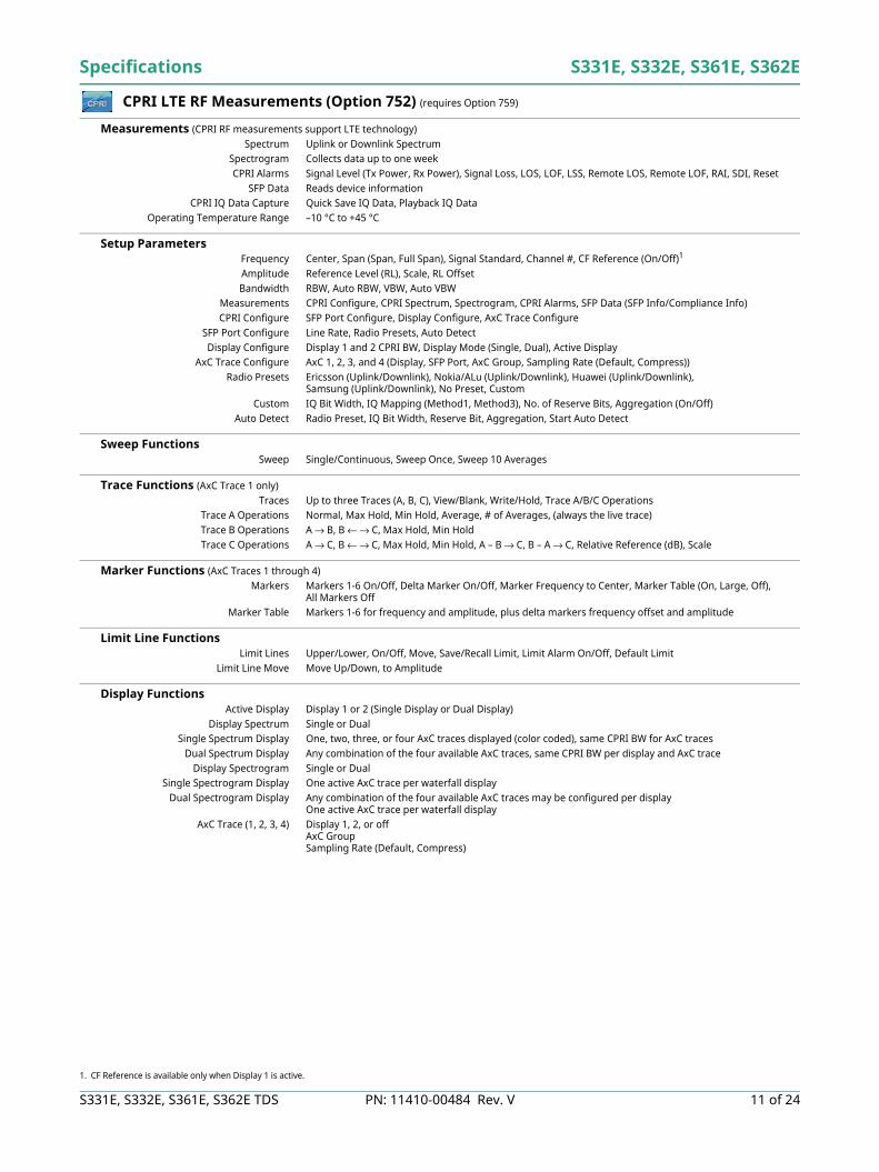
CPRI LTE RF Measurements (Option 752) (requires Option 759)
Measurements (CPRI RF measurements support LTE technology)Spectrum Uplink or Downlink Spectrum
Spectrogram Collects data up to one weekCPRI Alarms Signal Level (Tx Power, Rx Power), Signal Loss, LOS, LOF, LSS, Remote LOS, Remote LOF, RAI, SDI, Reset
SFP Data Reads device informationCPRI IQ Data Capture Quick Save IQ Data, Playback IQ Data
Operating Temperature Range –10 °C to +45 °C
Setup Parameters Frequency Center, Span (Span, Full Span), Signal Standard, Channel #, CF Reference (On/Off)1
Amplitude Reference Level (RL), Scale, RL OffsetBandwidth RBW, Auto RBW, VBW, Auto VBW
Measurements CPRI Configure, CPRI Spectrum, Spectrogram, CPRI Alarms, SFP Data (SFP Info/Compliance Info)CPRI Configure SFP Port Configure, Display Configure, AxC Trace Configure
SFP Port Configure Line Rate, Radio Presets, Auto DetectDisplay Configure Display 1 and 2 CPRI BW, Display Mode (Single, Dual), Active Display
AxC Trace Configure AxC 1, 2, 3, and 4 (Display, SFP Port, AxC Group, Sampling Rate (Default, Compress)) Radio Presets Ericsson (Uplink/Downlink), Nokia/ALu (Uplink/Downlink), Huawei (Uplink/Downlink),
Samsung (Uplink/Downlink), No Preset, CustomCustom IQ Bit Width, IQ Mapping (Method1, Method3), No. of Reserve Bits, Aggregation (On/Off)
Auto Detect Radio Preset, IQ Bit Width, Reserve Bit, Aggregation, Start Auto Detect
Sweep Functions Sweep Single/Continuous, Sweep Once, Sweep 10 Averages
Trace Functions (AxC Trace 1 only)Traces Up to three Traces (A, B, C), View/Blank, Write/Hold, Trace A/B/C Operations
Trace A Operations Normal, Max Hold, Min Hold, Average, # of Averages, (always the live trace)Trace B Operations A → B, B ← → C, Max Hold, Min HoldTrace C Operations A → C, B ← → C, Max Hold, Min Hold, A – B → C, B – A → C, Relative Reference (dB), Scale
Marker Functions (AxC Traces 1 through 4)Markers Markers 1-6 On/Off, Delta Marker On/Off, Marker Frequency to Center, Marker Table (On, Large, Off),
All Markers OffMarker Table Markers 1-6 for frequency and amplitude, plus delta markers frequency offset and amplitude
Limit Line Functions Limit Lines Upper/Lower, On/Off, Move, Save/Recall Limit, Limit Alarm On/Off, Default Limit
Limit Line Move Move Up/Down, to Amplitude
Display Functions Active Display Display 1 or 2 (Single Display or Dual Display)
Display Spectrum Single or DualSingle Spectrum Display One, two, three, or four AxC traces displayed (color coded), same CPRI BW for AxC traces
Dual Spectrum Display Any combination of the four available AxC traces, same CPRI BW per display and AxC traceDisplay Spectrogram Single or Dual
Single Spectrogram Display One active AxC trace per waterfall displayDual Spectrogram Display Any combination of the four available AxC traces may be configured per display
One active AxC trace per waterfall displayAxC Trace (1, 2, 3, 4) Display 1, 2, or off
AxC GroupSampling Rate (Default, Compress)
1. CF Reference is available only when Display 1 is active.
S331E, S332E, S361E, S362E Specifications
12 of 24 PN: 11410-00484 Rev. V S331E, S332E, S361E, S362E TDS
CPRI LTE RF Measurements (Option 752) (continued)
Bandwidth Resolution Bandwidth (RBW) 300 Hz to 1 MHz in 1-3-10 sequence ±10 % (–3 dB bandwidth point) typical
Video Bandwidth (VBW) 30 Hz to 1 MHz in 1-3-10 sequence ±10 % (–3 dB bandwidth) typicalLine Bit Rate Line bit rate 1: 614.4 Mbit/s
Line bit rate 2: 1228.8 Mbit/sLine bit rate 3: 2457.6 Mbit/sLine bit rate 4: 3072.0 Mbit/sLine bit rate 5: 4915.2 Mbit/sLine bit rate 6: 6144.0 Mbit/sLine bit rate 7: 9830.4 Mbit/sLine bit rate 8: 10137.6 Mbit/s
CPRI Parameters IQ Sample Width 10 bits, 12 bits, 15 bits, 16 bits
Bandwidth 5 MHz, 10 MHz, 15 MHz, 20 MHz Aggregation On/Off
Specifications S331E, S332E, S361E, S362E
S331E, S332E, S361E, S362E TDS PN: 11410-00484 Rev. V 13 of 24
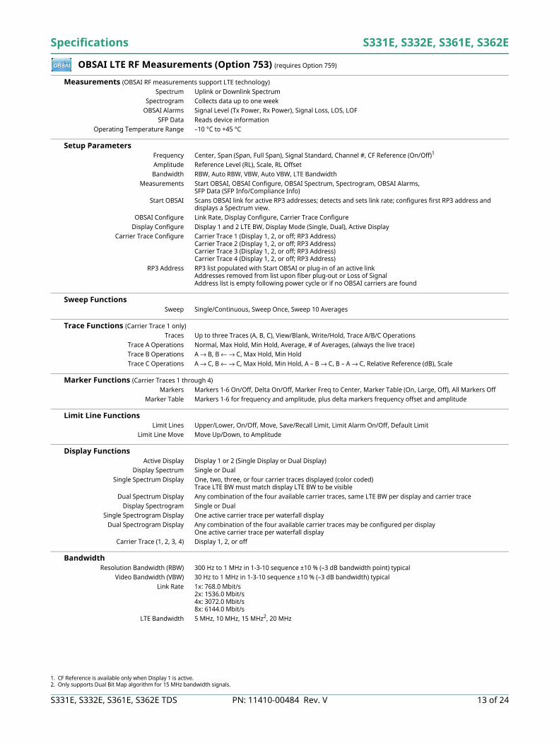
OBSAI LTE RF Measurements (Option 753) (requires Option 759)
Measurements (OBSAI RF measurements support LTE technology)Spectrum Uplink or Downlink Spectrum
Spectrogram Collects data up to one weekOBSAI Alarms Signal Level (Tx Power, Rx Power), Signal Loss, LOS, LOF
SFP Data Reads device informationOperating Temperature Range –10 °C to +45 °C
Setup Parameters Frequency Center, Span (Span, Full Span), Signal Standard, Channel #, CF Reference (On/Off)1
Amplitude Reference Level (RL), Scale, RL OffsetBandwidth RBW, Auto RBW, VBW, Auto VBW, LTE Bandwidth
Measurements Start OBSAI, OBSAI Configure, OBSAI Spectrum, Spectrogram, OBSAI Alarms, SFP Data (SFP Info/Compliance Info)
Start OBSAI Scans OBSAI link for active RP3 addresses; detects and sets link rate; configures first RP3 address and displays a Spectrum view.
OBSAI Configure Link Rate, Display Configure, Carrier Trace ConfigureDisplay Configure Display 1 and 2 LTE BW, Display Mode (Single, Dual), Active Display
Carrier Trace Configure Carrier Trace 1 (Display 1, 2, or off; RP3 Address)Carrier Trace 2 (Display 1, 2, or off; RP3 Address)Carrier Trace 3 (Display 1, 2, or off; RP3 Address)Carrier Trace 4 (Display 1, 2, or off; RP3 Address)
RP3 Address RP3 list populated with Start OBSAI or plug-in of an active linkAddresses removed from list upon fiber plug-out or Loss of SignalAddress list is empty following power cycle or if no OBSAI carriers are found
Sweep Functions Sweep Single/Continuous, Sweep Once, Sweep 10 Averages
Trace Functions (Carrier Trace 1 only)Traces Up to three Traces (A, B, C), View/Blank, Write/Hold, Trace A/B/C Operations
Trace A Operations Normal, Max Hold, Min Hold, Average, # of Averages, (always the live trace)Trace B Operations A → B, B ← → C, Max Hold, Min HoldTrace C Operations A → C, B ← → C, Max Hold, Min Hold, A – B → C, B – A → C, Relative Reference (dB), Scale
Marker Functions (Carrier Traces 1 through 4)Markers Markers 1-6 On/Off, Delta On/Off, Marker Freq to Center, Marker Table (On, Large, Off), All Markers Off
Marker Table Markers 1-6 for frequency and amplitude, plus delta markers frequency offset and amplitude
Limit Line Functions Limit Lines Upper/Lower, On/Off, Move, Save/Recall Limit, Limit Alarm On/Off, Default Limit
Limit Line Move Move Up/Down, to Amplitude
Display Functions Active Display Display 1 or 2 (Single Display or Dual Display)
Display Spectrum Single or DualSingle Spectrum Display One, two, three, or four carrier traces displayed (color coded)
Trace LTE BW must match display LTE BW to be visibleDual Spectrum Display Any combination of the four available carrier traces, same LTE BW per display and carrier trace
Display Spectrogram Single or DualSingle Spectrogram Display One active carrier trace per waterfall display
Dual Spectrogram Display Any combination of the four available carrier traces may be configured per displayOne active carrier trace per waterfall display
Carrier Trace (1, 2, 3, 4) Display 1, 2, or off
Bandwidth Resolution Bandwidth (RBW) 300 Hz to 1 MHz in 1-3-10 sequence ±10 % (–3 dB bandwidth point) typical
Video Bandwidth (VBW) 30 Hz to 1 MHz in 1-3-10 sequence ±10 % (–3 dB bandwidth) typicalLink Rate 1x: 768.0 Mbit/s
2x: 1536.0 Mbit/s4x: 3072.0 Mbit/s8x: 6144.0 Mbit/s
LTE Bandwidth 5 MHz, 10 MHz, 15 MHz2, 20 MHz
1. CF Reference is available only when Display 1 is active.2. Only supports Dual Bit Map algorithm for 15 MHz bandwidth signals.
S331E, S332E, S361E, S362E Specifications
14 of 24 PN: 11410-00484 Rev. V S331E, S332E, S361E, S362E TDS
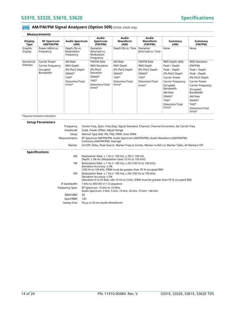
AM/FM/PM Signal Analyzers (Option 509) (S332E, S362E only)
Measurements
* Requires Sinewave modulation
Setup Parameters Frequency Center Freq, Span, Freq Step, Signal Standard, Channel, Channel Increment, Set Carrier FreqAmplitude Scale, Power Offset, Adjust Range
Setup Demod Type (AM, FM, PM), IFBW, Auto IFBWMeasurements RF Spectrum AM/FM/PM, Audio Spectrum (AM/FM/PM), Audio Waveform (AM/FM/PM),
Summary (AM/FM/PM), AverageMarker On/Off, Delta, Peak Search, Marker Freq to Center, Marker to Ref Lvl, Marker Table, All Markers Off
Specifications AM Modulation Rate: ± 1 Hz (< 100 Hz), ± 2% (> 100 Hz)
Depth: ± 5% for (Modulation rates 10 Hz to 100 kHz)FM Modulation Rate: ± 1 Hz (< 100 Hz); ± 2% (100 Hz to 100 kHz)
Deviation Accuracy: ± 5%(100 Hz to 100 kHz, IFBW must be greater than 95 % occupied BW)
PM Modulation Rate: ± 1 Hz (< 100 Hz); ± 2% (100 Hz to 100 kHz)Deviation Accuracy: ± 5%(deviation 0 to 93 Rad, rate 10 Hz to 5 kHz, IFBW must be greater than 95 % occupied BW)
IF bandwidth 1 kHz to 300 kHz in 1-3 sequenceFrequency Span RF Spectrum: 10 kHz to 10 MHz
Audio Spectrum: 2 kHz, 5 kHz, 10 kHz, 20 kHz, 70 kHz, 140 kHzRBW/VBW 30Span/RBW 100
Sweep time 50 µs to 50 ms (Audio Waveform)
Display Type
RF SpectrumAM/FM/PM
Audio Spectrum(AM)
Audio Spectrum(FM/PM)
Audio Waveform
(AM)
Audio Waveform (FM/PM)
Summary (AM)
Summary (FM/PM)
Graphic Display
Power (dBm) vs. Frequency
Depth (%) vs. Modulation Frequency
Deviation (kHz/rad) vs. Modulation Frequency
Depth (%) vs. Time Deviation (kHz/rad) vs. Time
None None
Numerical Displays
Carrier PowerCarrier FrequencyOccupied Bandwidth
AM Rate RMS Depth(Pk-Pk)/2 DepthSINAD*THD*Distortion/Total Vrms*
FM/PM RateRMS Deviation (Pk-Pk)/2 DeviationSINAD*THD*Distortion/Total Vrms*
AM RateRMS Depth (Pk-Pk)/2 DepthSINAD*THD*Distortion/Total Vrms*
FM/PM RateRMS Depth (Pk-Pk)/2 DepthSINAD*THD*Distortion/TotalVrms*
RMS Depth (AM)Peak + DepthPeak – Depth(Pk-Pk)/2 DepthCarrier PowerCarrier FrequencyOccupied BandwidthAM RateSINAD*THD*Distortion/Total Vrms*
RMS Deviation(FM/PM)Peak + DepthPeak – Depth(Pk-Pk)/2 DepthCarrier PowerCarrier FrequencyOccupied BandwidthAM RateSINAD*THD*Distortion/Total Vrms*
Specifications S331E, S332E, S361E, S362E
S331E, S332E, S361E, S362E TDS PN: 11410-00484 Rev. V 15 of 24
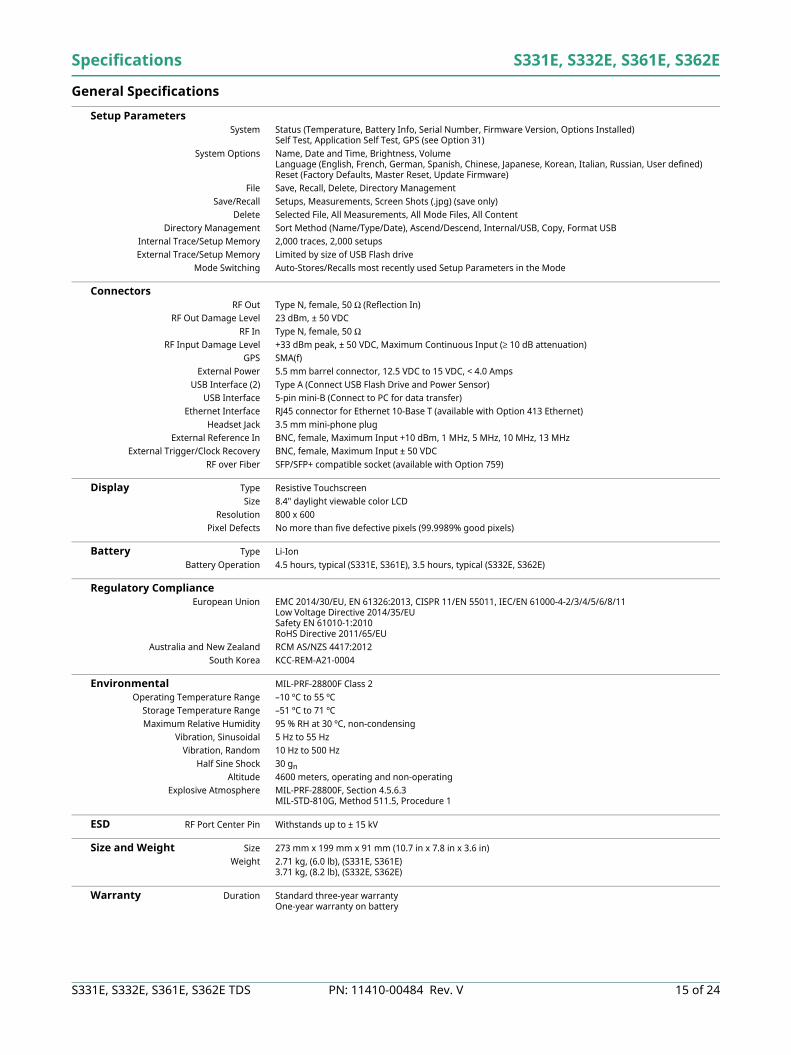
General Specifications
Setup Parameters System Status (Temperature, Battery Info, Serial Number, Firmware Version, Options Installed)
Self Test, Application Self Test, GPS (see Option 31)System Options Name, Date and Time, Brightness, Volume
Language (English, French, German, Spanish, Chinese, Japanese, Korean, Italian, Russian, User defined) Reset (Factory Defaults, Master Reset, Update Firmware)
File Save, Recall, Delete, Directory ManagementSave/Recall Setups, Measurements, Screen Shots (.jpg) (save only)
Delete Selected File, All Measurements, All Mode Files, All ContentDirectory Management Sort Method (Name/Type/Date), Ascend/Descend, Internal/USB, Copy, Format USB
Internal Trace/Setup Memory 2,000 traces, 2,000 setupsExternal Trace/Setup Memory Limited by size of USB Flash drive
Mode Switching Auto-Stores/Recalls most recently used Setup Parameters in the Mode
Connectors RF Out Type N, female, 50 Ω (Reflection In)
RF Out Damage Level 23 dBm, ± 50 VDCRF In Type N, female, 50 Ω
RF Input Damage Level +33 dBm peak, ± 50 VDC, Maximum Continuous Input (≥ 10 dB attenuation)GPS SMA(f)
External Power 5.5 mm barrel connector, 12.5 VDC to 15 VDC, < 4.0 AmpsUSB Interface (2) Type A (Connect USB Flash Drive and Power Sensor)
USB Interface 5-pin mini-B (Connect to PC for data transfer)Ethernet Interface RJ45 connector for Ethernet 10-Base T (available with Option 413 Ethernet)
Headset Jack 3.5 mm mini-phone plugExternal Reference In BNC, female, Maximum Input +10 dBm, 1 MHz, 5 MHz, 10 MHz, 13 MHz
External Trigger/Clock Recovery BNC, female, Maximum Input ± 50 VDCRF over Fiber SFP/SFP+ compatible socket (available with Option 759)
Display Type Resistive TouchscreenSize 8.4" daylight viewable color LCD
Resolution 800 x 600Pixel Defects No more than five defective pixels (99.9989% good pixels)
Battery Type Li-IonBattery Operation 4.5 hours, typical (S331E, S361E), 3.5 hours, typical (S332E, S362E)
Regulatory Compliance European Union EMC 2014/30/EU, EN 61326:2013, CISPR 11/EN 55011, IEC/EN 61000-4-2/3/4/5/6/8/11
Low Voltage Directive 2014/35/EUSafety EN 61010-1:2010RoHS Directive 2011/65/EU
Australia and New Zealand RCM AS/NZS 4417:2012South Korea KCC-REM-A21-0004
Environmental MIL-PRF-28800F Class 2Operating Temperature Range –10 ºC to 55 ºC
Storage Temperature Range –51 ºC to 71 ºCMaximum Relative Humidity 95 % RH at 30 ºC, non-condensing
Vibration, Sinusoidal 5 Hz to 55 HzVibration, Random 10 Hz to 500 Hz
Half Sine Shock 30 gnAltitude 4600 meters, operating and non-operating
Explosive Atmosphere MIL-PRF-28800F, Section 4.5.6.3 MIL-STD-810G, Method 511.5, Procedure 1
ESD RF Port Center Pin Withstands up to ± 15 kV
Size and Weight Size 273 mm x 199 mm x 91 mm (10.7 in x 7.8 in x 3.6 in)Weight 2.71 kg, (6.0 lb), (S331E, S361E)
3.71 kg, (8.2 lb), (S332E, S362E)
Warranty Duration Standard three-year warrantyOne-year warranty on battery
S331E, S332E, S361E, S362E Specifications
16 of 24 PN: 11410-00484 Rev. V S331E, S332E, S361E, S362E TDS
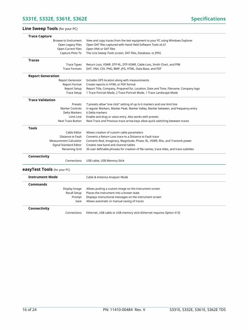
Line Sweep Tools (for your PC)
Trace Capture Browse to Instrument View and copy traces from the test equipment to your PC using Windows Explorer
Open Legacy Files Open DAT files captured with Hand Held Software Tools v6.61Open Current Files Open VNA or DAT files
Capture Plots To The Line Sweep Tools screen, DAT files, Database, or JPEG
Traces Trace Types Return Loss, VSWR, DTF-RL, DTF-VSWR, Cable Loss, Smith Chart, and PIM
Trace Formats DAT, VNA, CSV, PNG, BMP, JPG, HTML, Data Base, and PDF
Report Generation Report Generator Includes GPS location along with measurements
Report Format Create reports in HTML or PDF formatReport Setup Report Title, Company, Prepared for, Location, Date and Time, Filename, Company logo
Trace Setup 1 Trace Portrait Mode, 2 Trace Portrait Mode, 1 Trace Landscape Mode
Trace Validation Presets 7 presets allow “one click” setting of up to 6 markers and one limit line
Marker Controls 6 regular Markers, Marker Peak, Marker Valley, Marker between, and frequency entryDelta Markers 6 Delta markers
Limit Line Enable and drag or value entry. Also works with presetsNext Trace Button Next Trace and Previous trace arrow keys allow quick switching between traces
Tools Cable Editor Allows creation of custom cable parameters
Distance to Fault Converts a Return Loss trace to a Distance to Fault traceMeasurement Calculator Converts Real, Imaginary, Magnitude, Phase, RL, VSWR, Rho, and Transmit power
Signal Standard Editor Creates new band and channel tablesRenaming Grid 36 user definable phrases for creation of file names, trace titles, and trace subtitles
Connectivity Connections USB cable, USB Memory Stick
easyTest Tools (for your PC)
Instrument Mode Cable & Antenna Analyzer Mode
Commands Display Image Allows putting a custom image on the instrument screen
Recall Setup Places the instrument into a known statePrompt Displays instructional messages on the instrument screen
Save Allows automatic or manual saving of traces
Connectivity Connections Ethernet, USB cable or USB memory stick (Ethernet requires Option 413)
Specifications S331E, S332E, S361E, S362E
S331E, S332E, S361E, S362E TDS PN: 11410-00484 Rev. V 17 of 24
Master Software Tools (for your PC)
Mapping (GPS Required)Spectrum Analyzer Mode MapInfo, MapPoint
Mobile WiMAX OTA, LTE OTA Options Google Earth, Google Maps, MapInfo
Folder Spectrogram (Spectrum Monitoring for Interference Analysis and Spectrum Clearing)Folder Spectrogram – 2D View Creates a composite file of multiple traces
Peak Power, Total Power, Peak Frequency, Histogram, Average Power (Max/Min)File Filter (Violations over limit lines or deviations from averages)Playback
Video Folder Spectrogram – 2D View Create AVI file to export for management review/reportsFolder Spectrogram – 3D View Views (Set Threshold, Markers)
- 3D (Rotate X, Y, Z Axis, Level Scale, Signal ID) - Playback (Frequency and/or Time Domain)
List/Parameter Editors Traces Add, delete, and modify limit lines and markers
Product Updates Auto-checks Anritsu website for latest revision firmwarePass/Fail Create, download, or edit Signal Analysis Pass/Fail Limits
Languages Add custom language or modify non-English language menus
Connectivity Connections Connect to PC using USB or Ethernet (Ethernet requires Option 413)
Remote Operation Operate unit remotely with MST Remote Access Tool
Web Remote Control (requires Ethernet Option 413)
Control Full instrument control through a browser – all instrument functions except power switch and rotary knob
Connections RJ45 Ethernet jackThird party Wi-Fi router
Protocol HTTP/TCP/IPPhysical Layer Cat 5 Cable, Wi-Fi router compatible
Software Required HTML 5 Compliant Browser – Newer versions of Chrome, Firefox, Internet Explorer and othersOperating System iOS, Windows, Linux, Android operating systems that can host the HTML 5 Compliant browserRemote Hardware PCs, Tablets, and Smart Phones with Ethernet or Wi-Fi connections and a HTML 5 Compliant browser
Download Individual instrument files downloaded via browserMultiple instrument files and directories zipped and downloaded via browserScreen capture capability
Display Modes Normal: All modes & displays supportedFast: Spectrum traces update faster (up to 5 updates per second)
Password The instrument can be password protectedPasswords may be used to manage who is controlling the instrument
Users/Instruments One user/device can view and control many instruments
Programmable Remote Control
Functionality Many instrument functions are programmable. See the Programming Manual for details.
Programming Language Standard Commands for Programmable Instruments (SCPI)Interfaces USB, Ethernet (with Option 413)
Available Drivers LabView (visit NI.com for driver)
S331E, S332E, S361E, S362E Specifications
18 of 24 PN: 11410-00484 Rev. V S331E, S332E, S361E, S362E TDS
Ordering Information – Options
S331E S332E S361E S362E Description
2 MHz to 4 GHz 2 MHz to 4 GHz 2 MHz to 6 GHz 2 MHz to 6 GHz Cable and Antenna Analyzer9 kHz to 4 GHz 9 kHz to 6 GHz Spectrum Analyzer
Options Options Options OptionsS331E-0021 S332E-0021 S361E-0021 S362E-0021 2-Port Transmission Measurement
S331E-0010 S332E-0010 S361E-0010 S362E-0010 Bias-Tee (requires Option 21 for S331E /S361E)
S331E-0019 S332E-0019 S361E-0019 S362E-0019 High-Accuracy Power Meter (requires External Power Sensor)
S332E-0029 S362E-0029 Power Meter
S332E-0025 S362E-0025 Interference Analyzer (recommend Option 31)
S332E-0027 S362E-0027 Channel Scanner
S332E-0028 S362E-0028 C/W Signal Generator (requires CW Signal Generator Kit, P/N 69793)
S331E-0031 S332E-0031 S361E-0031 S362E-0031 GPS Receiver (requires Antenna)
S332E-0090 S362E-0090 Gated Sweep
S331E-0413 S332E-0413 S361E-0413 S362E-0413 Ethernet Connectivity
S332E-0431 S362E-0431 Coverage Mapping (requires Option 31)
S332E-0444 S362E-0444 EMF Measurements (requires Anritsu Isotropic Antenna)
S332E-0509 S362E-0509 AM/FM/PM Analyzer
S331E-0752 S332E-0752 S361E-0752 S362E-0752 CPRI LTE RF Measurements(requires Option 759)
S331E-0753 S332E-0753 S361E-0753 S362E-0753 OBSAI LTE RF Measurements (requires Option 759)
S331E-0759 S332E-0759 S361E-0759 S362E-0759 RF over Fiber hardware (requires Option 752 or 753)
S331E-0098 S332E-0098 S361E-0098 S362E-0098 Standard Calibration (ANSI 2540-1-1994)S331E-0099 S332E-0099 S361E-0099 S362E-0099 Premium Calibration to Z540 plus test data
Specifications S331E, S332E, S361E, S362E
S331E, S332E, S361E, S362E TDS PN: 11410-00484 Rev. V 19 of 24
Standard Accessories (included with instrument)
Power Sensors (for complete ordering information, see the respective data sheets of each sensor)
Manuals (available at www.anritsu.com)
Trouble Shooting Guides (available at www.anritsu.com)
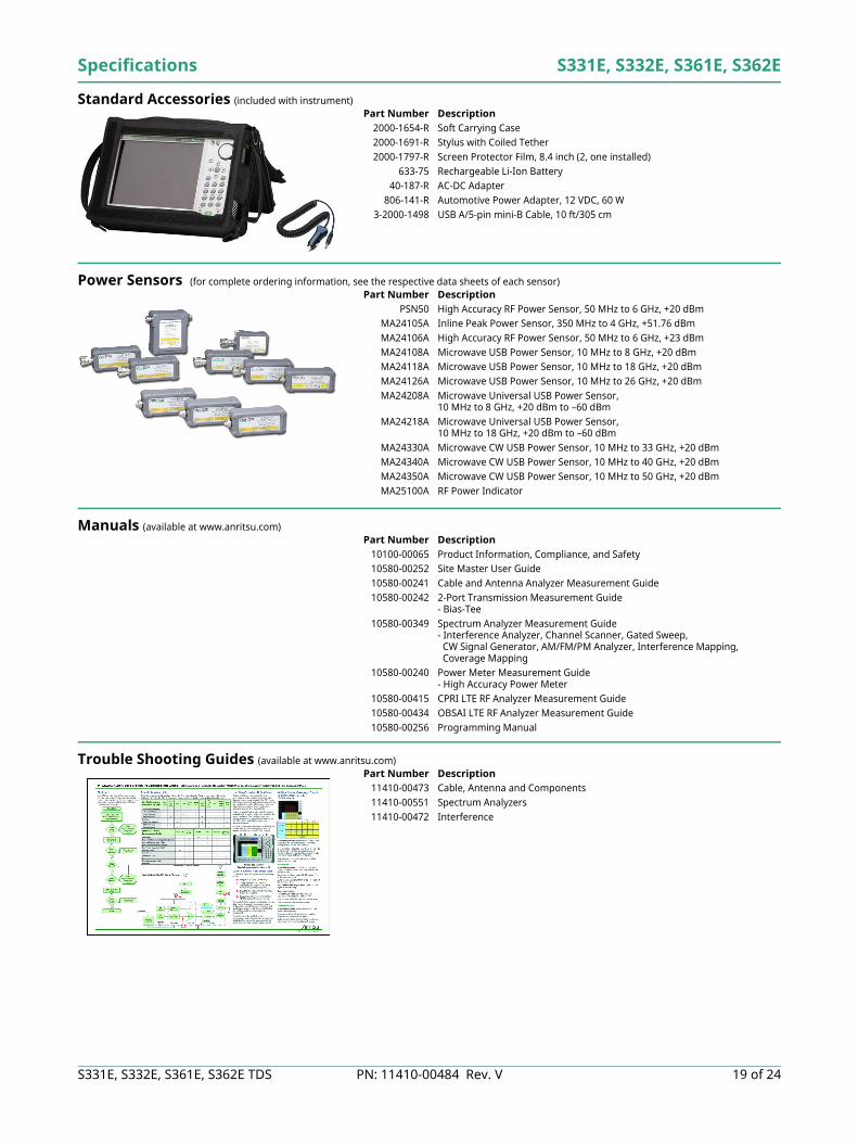
Part Number Description2000-1654-R Soft Carrying Case2000-1691-R Stylus with Coiled Tether2000-1797-R Screen Protector Film, 8.4 inch (2, one installed)
633-75 Rechargeable Li-Ion Battery40-187-R AC-DC Adapter
806-141-R Automotive Power Adapter, 12 VDC, 60 W3-2000-1498 USB A/5-pin mini-B Cable, 10 ft/305 cm
Part Number DescriptionPSN50 High Accuracy RF Power Sensor, 50 MHz to 6 GHz, +20 dBm
MA24105A Inline Peak Power Sensor, 350 MHz to 4 GHz, +51.76 dBmMA24106A High Accuracy RF Power Sensor, 50 MHz to 6 GHz, +23 dBmMA24108A Microwave USB Power Sensor, 10 MHz to 8 GHz, +20 dBmMA24118A Microwave USB Power Sensor, 10 MHz to 18 GHz, +20 dBmMA24126A Microwave USB Power Sensor, 10 MHz to 26 GHz, +20 dBmMA24208A Microwave Universal USB Power Sensor,
10 MHz to 8 GHz, +20 dBm to –60 dBmMA24218A Microwave Universal USB Power Sensor,
10 MHz to 18 GHz, +20 dBm to –60 dBmMA24330A Microwave CW USB Power Sensor, 10 MHz to 33 GHz, +20 dBmMA24340A Microwave CW USB Power Sensor, 10 MHz to 40 GHz, +20 dBmMA24350A Microwave CW USB Power Sensor, 10 MHz to 50 GHz, +20 dBmMA25100A RF Power Indicator
Part Number Description10100-00065 Product Information, Compliance, and Safety10580-00252 Site Master User Guide10580-00241 Cable and Antenna Analyzer Measurement Guide10580-00242 2-Port Transmission Measurement Guide
- Bias-Tee10580-00349 Spectrum Analyzer Measurement Guide
- Interference Analyzer, Channel Scanner, Gated Sweep, CW Signal Generator, AM/FM/PM Analyzer, Interference Mapping, Coverage Mapping
10580-00240 Power Meter Measurement Guide- High Accuracy Power Meter
10580-00415 CPRI LTE RF Analyzer Measurement Guide10580-00434 OBSAI LTE RF Analyzer Measurement Guide10580-00256 Programming Manual
Part Number Description11410-00473 Cable, Antenna and Components11410-00551 Spectrum Analyzers11410-00472 Interference
S331E, S332E, S361E, S362E Specifications
20 of 24 PN: 11410-00484 Rev. V S331E, S332E, S361E, S362E TDS
Optional Accessories
Calibration Components, 50 Ω
Calibration Components, 75 Ω
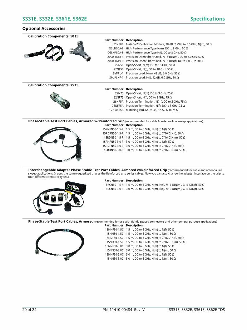
Phase-Stable Test Port Cables, Armored w/Reinforced Grip (recommended for cable & antenna line sweep applications)
Interchangeable Adapter Phase Stable Test Port Cables, Armored w/Reinforced Grip (recommended for cable and antenna line sweep applications. It uses the same ruggedized grip as the Reinforced grip series cables. Now you can also change the adapter interface on the grip to four different connector types.)
Phase-Stable Test Port Cables, Armored (recommended for use with tightly spaced connectors and other general purpose applications)
Part Number DescriptionICN50B InstaCal™ Calibration Module, 38 dB, 2 MHz to 6.0 GHz, N(m), 50 Ω
OSLN50A-8 High Performance Type N(m), DC to 8 GHz, 50 ΩOSLNF50A-8 High Performance Type N(f), DC to 8 GHz, 50 Ω 2000-1618-R Precision Open/Short/Load, 7/16 DIN(m), DC to 6.0 GHz 50 Ω2000-1619-R Precision Open/Short/Load, 7/16 DIN(f), DC to 6.0 GHz 50 Ω
22N50 Open/Short, N(m), DC to 18 GHz, 50 Ω22NF50 Open/Short, N(f), DC to 18 GHz, 50 Ω
SM/PL-1 Precision Load, N(m), 42 dB, 6.0 GHz, 50 ΩSM/PLNF-1 Precision Load, N(f), 42 dB, 6.0 GHz, 50 Ω
Part Number Description22N75 Open/Short, N(m), DC to 3 GHz, 75 Ω
22NF75 Open/Short, N(f), DC to 3 GHz, 75 Ω26N75A Precision Termination, N(m), DC to 3 GHz, 75 Ω
26NF75A Precision Termination, N(f), DC to 3 GHz, 75 Ω12N50-75B Matching Pad, DC to 3 GHz, 50 Ω to 75 Ω
Part Number Description15RNFN50-1.5-R 1.5 m, DC to 6 GHz, N(m) to N(f), 50 Ω15RDFN50-1.5-R 1.5 m, DC to 6 GHz, N(m) to 7/16 DIN(f), 50 Ω15RDN50-1.5-R 1.5 m, DC to 6 GHz, N(m) to 7/16 DIN(m), 50 Ω
15RNFN50-3.0-R 3.0 m, DC to 6 GHz, N(m) to N(f), 50 Ω15RDFN50-3.0-R 3.0 m, DC to 6 GHz, N(m) to 7/16 DIN(f), 50 Ω15RDN50-3.0-R 3.0 m, DC to 6 GHz, N(m) to 7/16 DIN(m), 50 Ω
Part Number Description15RCN50-1.5-R 1.5 m, DC to 6 GHz, N(m), N(f), 7/16 DIN(m), 7/16 DIN(f), 50 Ω15RCN50-3.0-R 3.0 m, DC to 6 GHz, N(m), N(f), 7/16 DIN(m), 7/16 DIN(f), 50 Ω
Part Number Description15NNF50-1.5C 1.5 m, DC to 6 GHz, N(m) to N(f), 50 Ω15NN50-1.5C 1.5 m, DC to 6 GHz, N(m) to N(m), 50 Ω
15NDF50-1.5C 1.5 m, DC to 6 GHz, N(m) to 7/16 DIN(f), 50 Ω15ND50-1.5C 1.5 m, DC to 6 GHz, N(m) to 7/16 DIN(m), 50 Ω
15NNF50-3.0C 3.0 m, DC to 6 GHz, N(m) to N(f), 50 Ω15NN50-3.0C 3.0 m, DC to 6 GHz, N(m) to N(m), 50 Ω
15NNF50-5.0C 5.0 m, DC to 6 GHz, N(m) to N(f), 50 Ω15NN50-5.0C 5.0 m, DC to 6 GHz, N(m) to N(m), 50 Ω
Specifications S331E, S332E, S361E, S362E
S331E, S332E, S361E, S362E TDS PN: 11410-00484 Rev. V 21 of 24
Optional Accessories (continued)
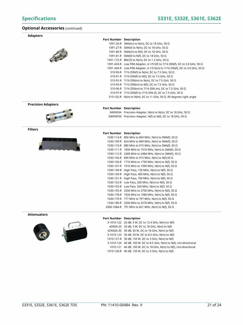
Adapters
Precision Adapters
Filters
Attenuators
Part Number Description1091-26-R SMA(m) to N(m), DC to 18 GHz, 50 Ω1091-27-R SMA(f) to N(m), DC to 18 GHz, 50 Ω1091-80-R SMA(m) to N(f), DC to 18 GHz, 50 Ω1091-81-R SMA(f) to N(f), DC to 18 GHz, 50 Ω
1091-172-R BNC(f) to N(m), DC to 1.3 GHz, 50 Ω1091-433-R Low PIM Adapter, 4.1/9.5(f) to 7/16 DIN(f), DC to 3.0 GHz, 50 Ω1091-434-R Low PIM Adapter, 4.1/9.5(m) to 7/16 DIN(f), DC to 3.0 GHz, 50 Ω
510-90-R 7/16 DIN(f) to N(m), DC to 7.5 GHz, 50 Ω510-91-R 7/16 DIN(f) to N(f), DC to 7.5 GHz, 50 Ω510-92-R 7/16 DIN(m) to N(m), DC to 7.5 GHz, 50 Ω510-93-R 7/16 DIN(m) to N(f), DC to 7.5 GHz, 50 Ω510-96-R 7/16 DIN(m) to 7/16 DIN (m), DC to 7.5 GHz, 50 Ω510-97-R 7/16 DIN(f) to 7/16 DIN (f), DC to 7.5 GHz, 50 Ω
510-102-R N(m) to N(m), DC to 11 GHz, 50 Ω, 90 degrees right angle
Part Number Description34NN50A Precision Adapter, N(m) to N(m), DC to 18 GHz, 50 Ω
34NFNF50 Precision Adapter, N(f) to N(f), DC to 18 GHz, 50 Ω
Part Number Description1030-114-R 806 MHz to 869 MHz, N(m) to SMA(f), 50 Ω1030-109-R 824 MHz to 849 MHz, N(m) to SMA(f), 50 Ω1030-110-R 880 MHz to 915 MHz, N(m) to SMA(f), 50 Ω1030-111-R 1850 MHz to 1910 MHz, N(m) to SMA(f), 50 Ω1030-112-R 2400 MHz to 2484 MHz, N(m) to SMA(f), 50 Ω1030-105-R 890 MHz to 915 MHz, N(m) to N(f),50 Ω1030-106-R 1710 MHz to 1790 MHz, N(m) to N(f), 50 Ω1030-107-R 1910 MHz to 1990 MHz, N(m) to N(f), 50 Ω1030-149-R High Pass, 150 MHz, N(m) to N(f), 50 Ω1030-150-R High Pass, 400 MHz, N(m) to N(f), 50 Ω1030-151-R High Pass, 700 MHz, N(m) to N(f), 50 Ω1030-152-R Low Pass, 200 MHz, N(m) to N(f), 50 Ω1030-153-R Low Pass, 550 MHz, N(m) to N(f), 50 Ω1030-155-R 2500 MHz to 2700 MHz, N(m) to N(f), 50 Ω1030-178-R 1920 MHz to 1980 MHz, N(m) to N(f), 50 Ω1030-179-R 777 MHz to 797 MHz, N(m) to N(f), 50 Ω1030-180-R 2500 MHz to 2570 MHz, N(m) to N(f), 50 Ω
2000-1684-R 791 MHz to 821 MHz, N(m) to N(f), 50 Ω
Part Number Description3-1010-122 20 dB, 5 W, DC to 12.4 GHz, N(m) to N(f)
42N50-20 20 dB, 5 W, DC to 18 GHz, N(m) to N(f)42N50A-30 30 dB, 50 W, DC to 18 GHz, N(m) to N(f)3-1010-123 30 dB, 50 W, DC to 8.5 GHz, N(m) to N(f)1010-127-R 30 dB, 150 W, DC to 3 GHz, N(m) to N(f)3-1010-124 40 dB, 100 W, DC to 8.5 GHz, N(m) to N(f), Uni-directional
1010-121 40 dB, 100 W, DC to 18 GHz, N(m) to N(f), Uni-directional1010-128-R 40 dB, 150 W, DC to 3 GHz, N(m) to N(f)
S331E, S332E, S361E, S362E Specifications
22 of 24 PN: 11410-00484 Rev. V S331E, S332E, S361E, S362E TDS
Optional Accessories (continued)
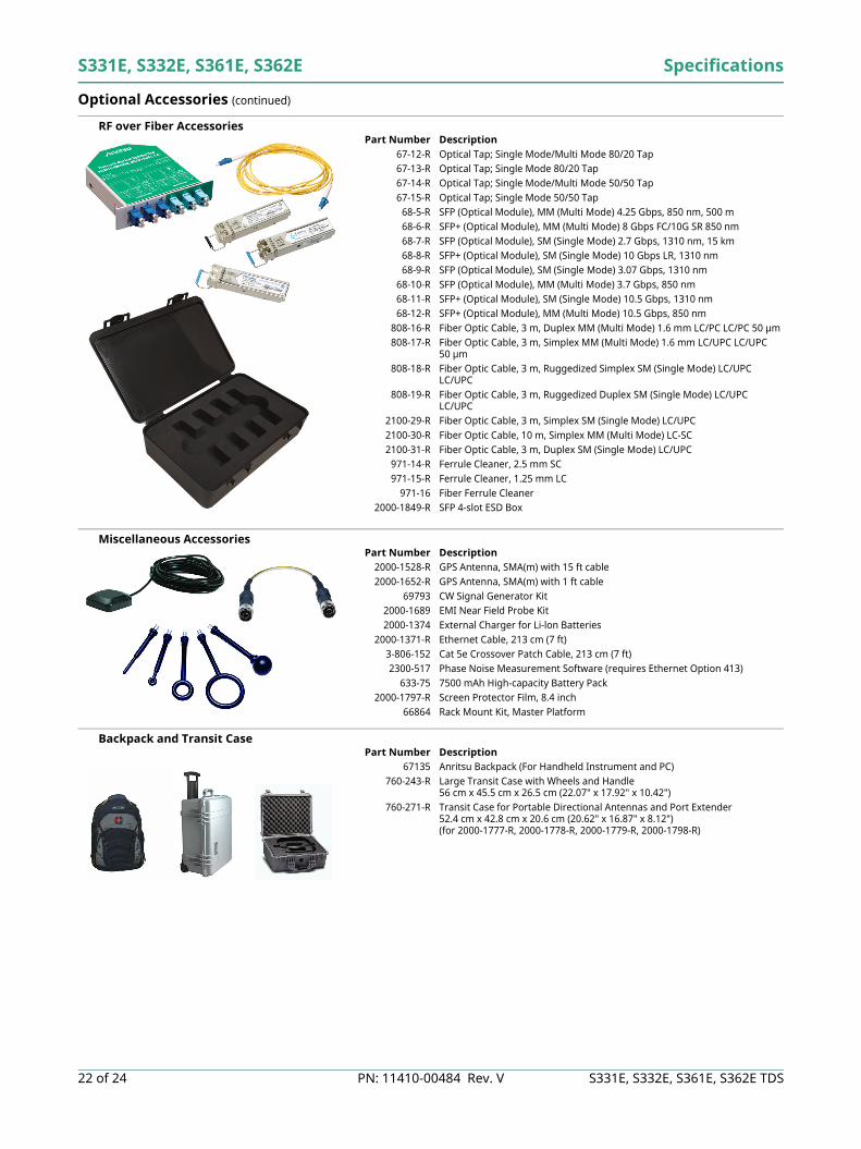
RF over Fiber Accessories
Miscellaneous Accessories
Backpack and Transit Case
Part Number Description67-12-R Optical Tap; Single Mode/Multi Mode 80/20 Tap67-13-R Optical Tap; Single Mode 80/20 Tap67-14-R Optical Tap; Single Mode/Multi Mode 50/50 Tap67-15-R Optical Tap; Single Mode 50/50 Tap
68-5-R SFP (Optical Module), MM (Multi Mode) 4.25 Gbps, 850 nm, 500 m68-6-R SFP+ (Optical Module), MM (Multi Mode) 8 Gbps FC/10G SR 850 nm68-7-R SFP (Optical Module), SM (Single Mode) 2.7 Gbps, 1310 nm, 15 km68-8-R SFP+ (Optical Module), SM (Single Mode) 10 Gbps LR, 1310 nm68-9-R SFP (Optical Module), SM (Single Mode) 3.07 Gbps, 1310 nm
68-10-R SFP (Optical Module), MM (Multi Mode) 3.7 Gbps, 850 nm68-11-R SFP+ (Optical Module), SM (Single Mode) 10.5 Gbps, 1310 nm68-12-R SFP+ (Optical Module), MM (Multi Mode) 10.5 Gbps, 850 nm
808-16-R Fiber Optic Cable, 3 m, Duplex MM (Multi Mode) 1.6 mm LC/PC LC/PC 50 µm808-17-R Fiber Optic Cable, 3 m, Simplex MM (Multi Mode) 1.6 mm LC/UPC LC/UPC
50 µm808-18-R Fiber Optic Cable, 3 m, Ruggedized Simplex SM (Single Mode) LC/UPC
LC/UPC808-19-R Fiber Optic Cable, 3 m, Ruggedized Duplex SM (Single Mode) LC/UPC
LC/UPC2100-29-R Fiber Optic Cable, 3 m, Simplex SM (Single Mode) LC/UPC2100-30-R Fiber Optic Cable, 10 m, Simplex MM (Multi Mode) LC-SC2100-31-R Fiber Optic Cable, 3 m, Duplex SM (Single Mode) LC/UPC
971-14-R Ferrule Cleaner, 2.5 mm SC971-15-R Ferrule Cleaner, 1.25 mm LC
971-16 Fiber Ferrule Cleaner2000-1849-R SFP 4-slot ESD Box
Part Number Description2000-1528-R GPS Antenna, SMA(m) with 15 ft cable2000-1652-R GPS Antenna, SMA(m) with 1 ft cable
69793 CW Signal Generator Kit2000-1689 EMI Near Field Probe Kit2000-1374 External Charger for Li-lon Batteries
2000-1371-R Ethernet Cable, 213 cm (7 ft)3-806-152 Cat 5e Crossover Patch Cable, 213 cm (7 ft)2300-517 Phase Noise Measurement Software (requires Ethernet Option 413)
633-75 7500 mAh High-capacity Battery Pack2000-1797-R Screen Protector Film, 8.4 inch
66864 Rack Mount Kit, Master Platform
Part Number Description67135 Anritsu Backpack (For Handheld Instrument and PC)
760-243-R Large Transit Case with Wheels and Handle56 cm x 45.5 cm x 26.5 cm (22.07" x 17.92" x 10.42")
760-271-R Transit Case for Portable Directional Antennas and Port Extender52.4 cm x 42.8 cm x 20.6 cm (20.62" x 16.87" x 8.12")(for 2000-1777-R, 2000-1778-R, 2000-1779-R, 2000-1798-R)

Specifications S331E, S332E, S361E, S362E
S331E, S332E, S361E, S362E TDS PN: 11410-00484 Rev. V 23 of 24
Optional Accessories (continued)
Directional Antennas
Isotropic Antennas
Portable Antennas
Mag Mount Broadband Antenna
Part Number Description2000-1411-R 822 MHz to 900 MHz, N(f), 10 dBd, Yagi2000-1412-R 885 MHz to 975 MHz, N(f), 10 dBd, Yagi2000-1413-R 1710 MHz to 1880 MHz, N(f), 10 dBd, Yagi2000-1414-R 1850 MHz to 1990 MHz, N(f), 9.3 dBd, Yagi2000-1415-R 2400 MHz to 2500 MHz, N(f), 10 dBd, Yagi2000-1416-R 1920 MHz to 2170 MHz, N(f), 10 dBd, Yagi
2000-1617 600 MHz to 21 GHz, N(f), 5-8 dBi to 12 GHz, 0-6 dBi to 21 GHz, Log Periodic2000-1659-R 698 MHz to 787 MHz, N(f), 8 dBd, Yagi2000-1660-R 1425 MHz to 1535 MHz, N(f), 12 dBd, Yagi2000-1677-R 300 MHz to 3 GHz, SMA(m), Log Periodic2000-1726-R Antenna, 2500 MHz to 2700 MHz, N(f), 12 dBd, Yagi2000-1747-R Antenna, Log Periodic, 300 MHz to 5000 MHz, N(f), 5.1 dBi, typical2000-1748-R Antenna, Log Periodic, 1 GHz to 18 GHz, N(f), 6 dBi, typical2000-1777-R Portable Directional Antenna, 9 kHz to 20 MHz, N(f)2000-1778-R Portable Directional Antenna, 20 MHz to 200 MHz, N(f)2000-1779-R Portable Directional Antenna, 200 MHz to 500 MHz, N(f)2000-1812-R Portable Yagi Antenna, 450 MHz to 512 MHz, N(f), 5 dBd2000-1825-R Portable Yagi Antenna, 380 MHz to 430 MHz, N(f), 5 dBd
MA2700A Handheld Interference Hunter
Part Number Description2000-1791-R Isotropic Antenna, 700 MHz to 6000 MHz, N(m)2000-1792-R Isotropic Antenna, 30 MHz to 3000 MHz, N(m)2000-1800-R Isotropic Antenna, 9 kHz to 300 MHz, N(m)
Part Number Description2000-1200-R 806 MHz to 866 MHz, SMA(m), 50 Ω2000-1473-R 870 MHz to 960 MHz, SMA(m), 50 Ω2000-1035-R 896 MHz to 941 MHz, SMA(m), 50 Ω (1/2 wave)2000-1030-R 1710 MHz to 1880 MHz, SMA(m), 50 Ω (1/2 wave)2000-1474-R 1710 MHz to 1880 MHz with knuckle elbow (1/2 wave)2000-1031-R 1850 MHz to 1990 MHz, SMA(m), 50 Ω (1/2 wave)2000-1475-R 1920 MHz to 1980 MHz and 2110 MHz to 2170 MHz, SMA(m), 50 Ω2000-1032-R 2400 MHz to 2500 MHz, SMA(m), 50 Ω (1/2 wave)2000-1361-R 2400 MHz to 2500 MHz, 5000 MHz to 6000 MHz, SMA(m), 50 Ω2000-1636-R Antenna Kit (Consists of: 2000-1030-R, 2000-1031-R, 2000-1032-R,
2000-1200-R, 2000-1035-R, 2000-1361-R, and carrying pouch)
Part Number Description2000-1647-R Cable 1: 698 MHz to 1200 MHz 2 dBi peak gain,
1700 MHz to 2700 MHz 5 dBi peak gain, N(m), 50 Ω, 10 ftCable 2: 3000 MHz to 6000 MHz 5 dBi peak gain, N(m), 50 Ω, 10 ftCable 3: GPS 26 dB gain, SMA(m), 50 Ω, 10 ft
2000-1645-R 694 MHz to 894 MHz 3 dBi peak gain, 1700 MHz to 2700 MHz 3 dBi peak gain, N(m), 50 Ω, 10 ft
2000-1646-R 750 MHz to 1250 MHz 3 dBi peak gain, 1650 MHz to 2000 MHz 5 dBi peak gain, 2100 MHz to 2700 MHz 3 dBi peak gain, N(m), 50 Ω, 10 ft
2000-1648-R 1700 MHz to 6000 MHz 3 dBi peak gain, N(m), 50 Ω, 10 ft

S331E, S332E, S361E, S362E TDS, PN: 11410-00484, Rev. VCopyright June 2017, Anritsu Company, USA. All Rights Reserved.
® Anritsu All trademarks are registered trademarks of their respective companies.Anritsu utilizes recycled paper and environmentally conscious inks and toner.
Data subject to change without notice.For the most recent specifications, visit: www.anritsu.com.2424 of 24
Training at AnritsuAnritsu has designed courses to help you stay up to date with technologies important to your job. For available training courses, visit: www.anritsu.com/training
United StatesAnritsu Company1155 East Collins Blvd, Suite 100 Richardson, TX 75081, U.S.A.Toll Free: 1-800-267-4878Phone: +1-972-644-1777Fax: +1-972-671-1877 CanadaAnritsu Electronics Ltd.700 Silver Seven Road, Suite 120 Kanata, Ontario K2V 1C3, CanadaPhone: +1-613-591-2003Fax: +1-613-591-1006 BrazilAnritsu Electrônica Ltda.Praça Amadeu Amaral, 27 - 1 Andar01327-010 Bela Vista, São Paulo, SP, BrazilPhone: +55-11-3283-2511Fax: +55-11-3288-6940 MexicoAnritsu Company, S.A. de C.V.Av. Ejército Nacional No. 579 Piso 9, Col. Granada11520 México, D.F., MéxicoPhone: +52-55-1101-2370Fax: +52-55-5254-3147 United KingdomAnritsu EMEA Ltd.200 Capability GreenLuton, Bedfordshire LU1 3LUUnited KingdomPhone: +44-1582-433280Fax: +44-1582-731303 FranceAnritsu S.A.12 Avenue du QuébecBâtiment Iris 1-Silic 61291140 Villebon-sur-Yvette, FrancePhone: +33-1-60-92-15-50Fax: +33-1-64-46-10-65 GermanyAnritsu GmbHNemetschek Haus, Konrad-Zuse-Platz 181829 München, GermanyPhone: +49-89-442308-0Fax: +49-89-442308-55
ItalyAnritsu S.r.l.Via Elio Vittorini 12900144 Roma, ItalyPhone: +39-06-509-9711Fax: +39-06-502-2425 SwedenAnritsu ABKistagången 20B164 40 KISTA, SwedenPhone: +46-8-534-707-00Fax: +46-8-534-707-30 FinlandAnritsu ABTeknobulevardi 3-5FI-01530 Vantaa, FinlandPhone: +358-20-741-8100Fax: +358-20-741-8111 DenmarkAnritsu A/SKay Fiskers Plads 92300 Copenhagen S, DenmarkPhone: +45-7211-2200Fax: +45-7211-2210 RussiaAnritsu EMEA Ltd.Representation Office in RussiaTverskaya str. 16/2, bld. 1, 7th floorMoscow, 125009, RussiaPhone: +7-495-363-1694Fax: +7-495-935-8962 SpainAnritsu EMEA Ltd.Representation Office in SpainEdificio Cuzco IV, Po. de la Castellana, 141, Pta. 828046, Madrid, SpainPhone: +34-915-726-761Fax: +34-915-726-621 United Arab EmiratesAnritsu EMEA Ltd.Dubai Liaison Office902, Aurora Tower,P O Box: 500311- Dubai Internet CityDubai, United Arab EmiratesPhone: +971-4-3758479Fax: +971-4-4249036
IndiaAnritsu India Private Limited2nd & 3rd Floor, #837/1, Binnamangla 1st StageIndiranagar, 100ft Road, Bangalore - 560038, IndiaPhone: +91-80-4058-1300Fax: +91-80-4058-1301 SingaporeAnritsu Pte. Ltd.11 Chang Charn Road, #04-01, Shriro HouseSingapore 159640Phone: +65-6282-2400Fax: +65-6282-2533 P.R. China (Shanghai)Anritsu (China) Co., Ltd.27th Floor, Tower ANew Caohejing International Business CenterNo. 391 Gui Ping Road Shanghai, Xu Hui Di DistrictShanghai 200233, P.R. ChinaPhone: +86-21-6237-0898Fax: +86-21-6237-0899 P.R. China (Hong Kong)Anritsu Company Ltd.Unit 1006-7, 10/F., Greenfield TowerConcordia PlazaNo. 1 Science Museum Road, Tsim Sha Tsui EastKowloon, Hong Kong, P. R. ChinaPhone: +852-2301-4980Fax: +852-2301-3545 JapanAnritsu Corporation8-5, Tamura-cho, Atsugi-shi Kanagawa, 243-0016 JapanPhone: +81-46-296-1221Fax: +81-46-296-1238 KoreaAnritsu Corporation, Ltd.5FL, 235 Pangyoyeok-ro, Bundang-gu, Seongnam-siGyeonggi-do, 13494 KoreaPhone: +82-31-696-7750Fax: +82-31-696-7751 AustraliaAnritsu Pty. Ltd.Unit 20, 21-35 Ricketts Road,Mount Waverley, Victoria 3149, AustraliaPhone: +61-3-9558-8177Fax: +61-3-9558-8255 TaiwanAnritsu Company Inc.7F, No. 316, Sec. 1, Neihu Rd, Taipei 114, TaiwanPhone: +886-2-8751-1816Fax: +886-2-8751-1817
List Revision Date: 20160317


![[TDB] Duct S for Europe (R410A, 50Hz, HP)€¦ · · 2015-06-18Technical Data Book ... Ver.1.0 Release SINGLE Big Duct for Europe (R410A, 50Hz, H/P) TDB 14.11 Ver.1.1 Delete Energy](https://img.pdfslide.us/doc/110x75/5af320b57f8b9abc7890ae79/tdb-duct-s-for-europe-r410a-50hz-hp-2015-06-18technical-data-book-ver10.jpg)