Embed Size (px)
Citation preview
Chapter 1
Site investigation
1.1 Geotechnical engineer
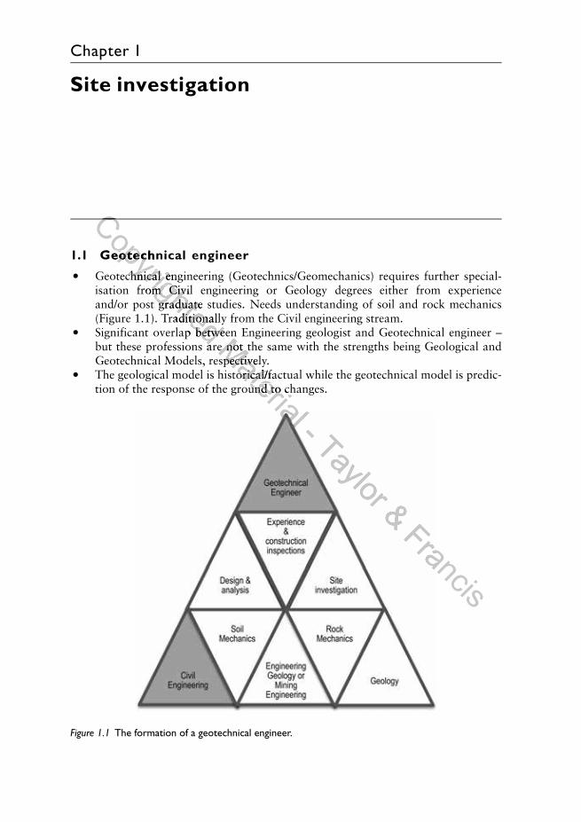
• Geotechnical engineering (Geotechnics/Geomechanics) requires further special-isation from Civil engineering or Geology degrees either from experienceand/or post graduate studies. Needs understanding of soil and rock mechanics(Figure 1.1). Traditionally from the Civil engineering stream.
• Significant overlap between Engineering geologist and Geotechnical engineer –but these professions are not the same with the strengths being Geological andGeotechnical Models, respectively.
• The geological model is historical/factual while the geotechnical model is predic-tion of the response of the ground to changes.
Figure 1.1 The formation of a geotechnical engineer.
Copyrighted
Copyrighted
1.1 Geotechnical engineer
Copyrighted
1.1 Geotechnical engineer
Geotechnical engineering (Geotechnics/Geomechanics) requires further special-
Copyrighted
Geotechnical engineering (Geotechnics/Geomechanics) requires further special-isation from Civil engineering or Geology degrees either from experience
Copyrighted isation from Civil engineering or Geology degrees either from experienceand/or post graduate studies. Needs understanding of soil and rock mechanics
Copyrighted and/or post graduate studies. Needs understanding of soil and rock mechanics(Figure 1.1). Traditionally from the Civil engineering stream.
Copyrighted (Figure 1.1). Traditionally from the Civil engineering stream.Significant overlap between Engineering geologist and Geotechnical engineer –
Copyrighted Significant overlap between Engineering geologist and Geotechnical engineer –but these professions are not the same with the strengths being Geological and
Copyrighted but these professions are not the same with the strengths being Geological andMaterial
Significant overlap between Engineering geologist and Geotechnical engineer –Material
Significant overlap between Engineering geologist and Geotechnical engineer –but these professions are not the same with the strengths being Geological andMaterial
but these professions are not the same with the strengths being Geological andMaterial
Geotechnical Models, respectively.Material
Geotechnical Models, respectively.The geological model is historical/factual while the geotechnical model is predic-
Material The geological model is historical/factual while the geotechnical model is predic-tion of the response of the ground to changes.
Material tion of the response of the ground to changes.
Material - Taylor & Francis
Francis
2 Handbook of Geotechnical Investigation and Design Tables
Table 1.1 Ground model inputs by specialists.
Geological model Ground model Geotechnical model
Engineering geologist Geotechnical engineer
Model by Geotechnical engineer in simple casesObtain site dataDevelop geological model – relevant geologicalstructures
Provide key ground related issues; site historyIdentify regional issues affecting siteWork with Geotechnical engineer to develop site
specific solution
Model by Engineering geologist in simple casesCarry out testing to an acceptable levelDevelop geotechnical models (parameters fordesign)
Recognise and provide site constraints – e.g.slopes or allowable bearing capacity; sitefuture use
Suggest ground solutionsWork with Engineering geologist to implement
ground issues into the design
1.2 Developing models
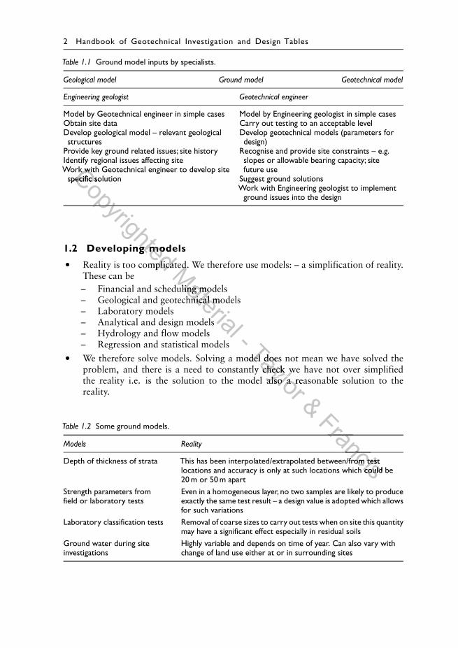
• Reality is too complicated. We therefore use models: – a simplification of reality.These can be– Financial and scheduling models– Geological and geotechnical models– Laboratory models– Analytical and design models– Hydrology and flow models– Regression and statistical models
• We therefore solve models. Solving a model does not mean we have solved theproblem, and there is a need to constantly check we have not over simplifiedthe reality i.e. is the solution to the model also a reasonable solution to thereality.
Table 1.2 Some ground models.
Models Reality
Depth of thickness of strata This has been interpolated/extrapolated between/from testlocations and accuracy is only at such locations which could be20 m or 50 m apart
Strength parameters fromfield or laboratory tests
Even in a homogeneous layer, no two samples are likely to produceexactly the same test result – a design value is adopted which allowsfor such variations
Laboratory classification tests Removal of coarse sizes to carry out tests when on site this quantitymay have a significant effect especially in residual soils
Ground water during siteinvestigations
Highly variable and depends on time of year. Can also vary withchange of land use either at or in surrounding sites
Copyrighted
Work with Geotechnical engineer to develop siteCopyrighted
Work with Geotechnical engineer to develop sitespecific solutionCopyrighted
specific solutionCopyrighted 1.2 Developing models
Copyrighted 1.2 Developing models
Reality is too complicated. We therefore use models: – a simplification of reality.
Copyrighted Reality is too complicated. We therefore use models: – a simplification of reality.Material
Reality is too complicated. We therefore use models: – a simplification of reality.Material
Reality is too complicated. We therefore use models: – a simplification of reality.
– Financial and scheduling models
Material
– Financial and scheduling models– Geological and geotechnical models
Material – Geological and geotechnical models
– Analytical and design models
Material – Analytical and design models
- Taylor
We therefore solve models. Solving a model does not mean we have solved theTaylor
We therefore solve models. Solving a model does not mean we have solved theproblem, and there is a need to constantly check we have not over simplified
Taylor problem, and there is a need to constantly check we have not over simplifiedthe reality i.e. is the solution to the model also a reasonable solution to the
Taylor the reality i.e. is the solution to the model also a reasonable solution to the
& Francis
Francis
Francis
FrancisDepth of thickness of strata This has been interpolated/extrapolated between/from test
FrancisDepth of thickness of strata This has been interpolated/extrapolated between/from test
Francislocations and accuracy is only at such locations which could be
Francislocations and accuracy is only at such locations which could be
Site investigation 3
Figure 1.2 Example of a geotechnical model.
1.3 Geotechnical involvement
• There are two approaches for acquiring geotechnical data– Accept the ground conditions as a design element, i.e. based on the structure/
development design location and configuration, and then obtain the relevantground conditions to design for/against. This is the traditional approach.
– Geotechnical input throughout the project by planning the structure/development with the ground as a considered input, i.e. the design, layout andconfiguration is influenced by the ground conditions. This is the recommendedapproach for minimisation of overall project costs.
• Geotechnical involvement should occur throughout the life of the project. Theinput varies depending on phase of project.
• The phasing of the investigation provides the benefit of improved quality andrelevance of the geotechnical data to the project.
Table 1.3 Geotechnical involvement.
Project phase Geotechnical study for types of projects
Small Medium Large
Feasibility/IAS Desktop study/ Desktop study Desktop studyPlanning site investigation Definition of needsPreliminary engineering Site Investigation (S.I.) Preliminary site investigationDetailed design Detailed site investigation
Construction Inspection Monitoring/inspection Monitoring/inspectionMaintenance Inspection
Copyrighted
Copyrighted Example of a geotechnical model.
Copyrighted Example of a geotechnical model.Material
Example of a geotechnical model.Material
Example of a geotechnical model.
1.3 Geotechnical involvementMaterial
1.3 Geotechnical involvement
There are two approaches for acquiring geotechnical data
Material There are two approaches for acquiring geotechnical data– Accept the ground conditions as a design element, i.e. based on the structure/
Material – Accept the ground conditions as a design element, i.e. based on the structure/
development design location and configuration, and then obtain the relevant
Material development design location and configuration, and then obtain the relevantground conditions to design for/against. This is the traditional approach.
Material ground conditions to design for/against. This is the traditional approach.- ground conditions to design for/against. This is the traditional approach.- ground conditions to design for/against. This is the traditional approach.– Geotechnical input throughout the project by planning the structure/
- – Geotechnical input throughout the project by planning the structure/Taylor
ground conditions to design for/against. This is the traditional approach.Taylor
ground conditions to design for/against. This is the traditional approach.– Geotechnical input throughout the project by planning the structure/Taylor
– Geotechnical input throughout the project by planning the structure/Taylor development with the ground as a considered input, i.e. the design, layout and
Taylor development with the ground as a considered input, i.e. the design, layout andconfiguration is influenced by the ground conditions. This is the recommended
Taylor configuration is influenced by the ground conditions. This is the recommendedapproach for minimisation of overall project costs.
Taylor approach for minimisation of overall project costs.Geotechnical involvement should occur throughout the life of the project. The
Taylor Geotechnical involvement should occur throughout the life of the project. The& Geotechnical involvement should occur throughout the life of the project. The& Geotechnical involvement should occur throughout the life of the project. The
The phasing of the investigation provides the benefit of improved quality and
& The phasing of the investigation provides the benefit of improved quality andFrancis
The phasing of the investigation provides the benefit of improved quality andFrancis
The phasing of the investigation provides the benefit of improved quality andFrancis
Francis
Francis
4 Handbook of Geotechnical Investigation and Design Tables
◦ Impact Assessment Study (IAS).◦ Planning may occur before or after IAS depending on the type of project.
1.4 Geotechnical requirements for the different project phases
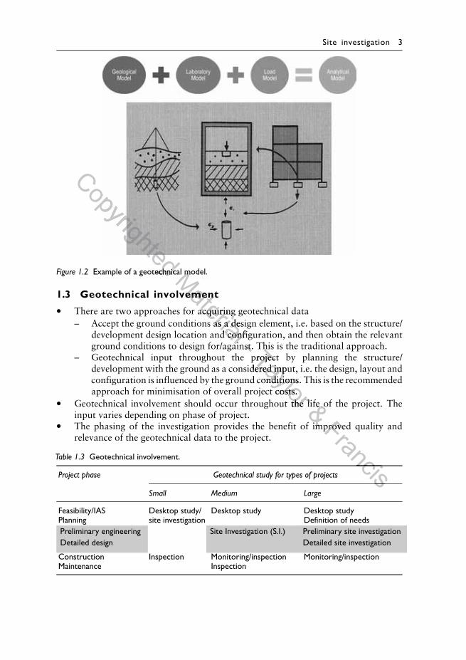
• The geotechnical study involves phasing of the study to get the maximum bene-fit. The benefits (∼20% per phase) are shown approximately evenly distributedthroughout the lifecycle of the project – but this ratio is project specific.
• Traditionally (and currently in most projects), most of the geotechnical effort(>90%) and costs are in the investigation and construction phases.
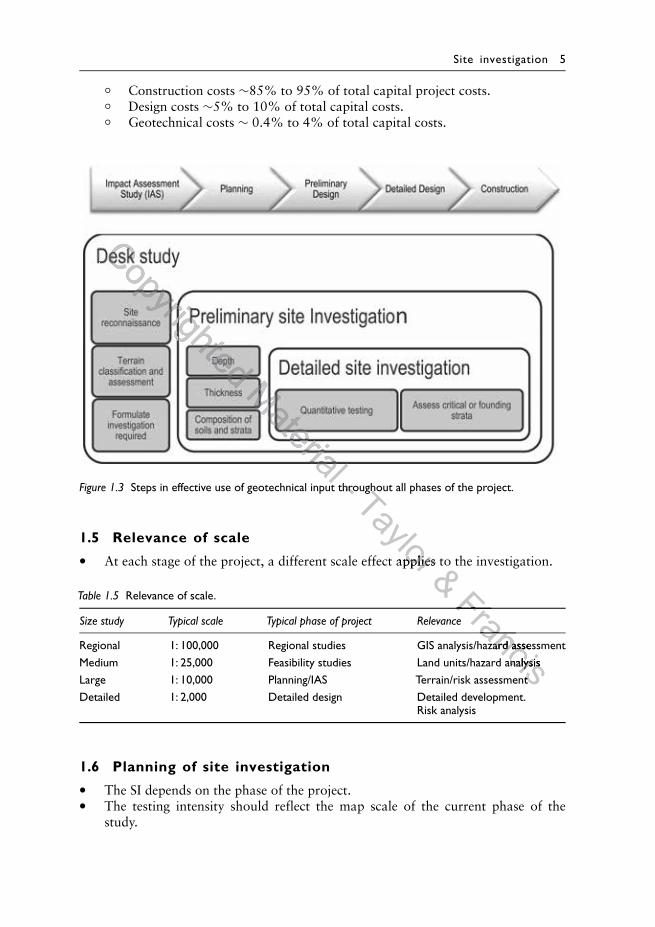
• Phasing of the SI determines the requirements for the next stage of SI (Figure 1.3).• The detailed investigation may make some of the preliminary investigation data
redundant. Iteration is also part of optimisation of geotechnical investigations.• The geotechnical input at any stage has a different type of benefit. The Quality
Assurance (QA) benefit during construction, is as important as optimising thelocation of the development correctly in the desktop study. The volume of testingas part of Q.A. may be significant and has not been included in the table. Thisconsiders the monitoring/instrumentation as the engineering input and not thetesting (QA) input
• The optimal approach during construction may allow reduced factors of safetyto be applied and so reduce the overall project costs. That approach may also berequired near critical areas without any reduction in factors of safety.
Table 1.4 Geotechnical requirements.
Geotechnical Key model Relative (100% total) Key data Commentsstudy
Effort Benefit
Desktopstudy
Geologicalmodel
<5% ∼20% Geological setting,existing data, sitehistory, aerialphotographs andterrain assessment
Minor SI costs (sitereconnaissance) withsignificant planningbenefits
Definitionof needs
<5% ∼20% Justify Investigationrequirements andanticipated costs
Safety plans and serviceschecks. Physical,environmental andallowable site access
Preliminary Geological & 10–20% ∼20% Depth, thickness and Preliminary investigationinvestigation geotechnical composition of soils of ≤20% of planned
model and strata detailed site investigation
Detailed siteinvestigation
Geotechnicalmodel
60–80% ∼20% Quantitative andcharacterisation ofcritical or foundingstrata
Laboratory analysis of20% of detailed soilprofile
Monitoring/inspection
<10% ∼20% Instrumentation asrequired. QA testing
Confirms modelsadopted or requirementsto adjust assumptions.Increased effort forobservational designapproach
Copyrighted
Phasing of the SI determines the requirements for the next stage of SI (Figure 1.3).Copyrighted
Phasing of the SI determines the requirements for the next stage of SI (Figure 1.3).The detailed investigation may make some of the preliminary investigation dataCopyrighted
The detailed investigation may make some of the preliminary investigation dataredundant. Iteration is also part of optimisation of geotechnical investigations.
Copyrighted
redundant. Iteration is also part of optimisation of geotechnical investigations.The geotechnical input at any stage has a different type of benefit. The Quality
Copyrighted
The geotechnical input at any stage has a different type of benefit. The QualityAssurance (QA) benefit during construction, is as important as optimising the
Copyrighted
Assurance (QA) benefit during construction, is as important as optimising thelocation of the development correctly in the desktop study. The volume of testing
Copyrighted
location of the development correctly in the desktop study. The volume of testingas part of Q.A. may be significant and has not been included in the table. This
Copyrighted as part of Q.A. may be significant and has not been included in the table. Thisconsiders the monitoring/instrumentation as the engineering input and not the
Copyrighted considers the monitoring/instrumentation as the engineering input and not thetesting (QA) input
Copyrighted testing (QA) inputThe optimal approach during construction may allow reduced factors of safety
Copyrighted The optimal approach during construction may allow reduced factors of safetyto be applied and so reduce the overall project costs. That approach may also be
Copyrighted to be applied and so reduce the overall project costs. That approach may also beMaterial
The optimal approach during construction may allow reduced factors of safetyMaterial
The optimal approach during construction may allow reduced factors of safetyto be applied and so reduce the overall project costs. That approach may also beMaterial
to be applied and so reduce the overall project costs. That approach may also berequired near critical areas without any reduction in factors of safety.
Material
required near critical areas without any reduction in factors of safety.
Material Geotechnical Key model Relative (100% total) Key data
Material Geotechnical Key model Relative (100% total) Key data
Material - Taylor
Taylor 20% Geological setting,
Taylor 20% Geological setting,
existing data, site
Taylor existing data, sitehistory, aerial
Taylor history, aerialphotographs and
Taylor photographs andterrain assessment
Taylor terrain assessment& 20% Justify Investigation& 20% Justify Investigation Safety plans and services& Safety plans and servicesFrancis
Safety plans and servicesFrancis
Safety plans and serviceschecks. Physical,Francis
checks. Physical,environmental andFrancisenvironmental andallowable site access
Francisallowable site access
FrancisPreliminary investigation
FrancisPreliminary investigation
Francis20% of planned
Francis20% of planned
Francisdetailed site investigation
Francisdetailed site investigation
Site investigation 5
◦ Construction costs ∼85% to 95% of total capital project costs.◦ Design costs ∼5% to 10% of total capital costs.◦ Geotechnical costs ∼ 0.4% to 4% of total capital costs.
Figure 1.3 Steps in effective use of geotechnical input throughout all phases of the project.
1.5 Relevance of scale
• At each stage of the project, a different scale effect applies to the investigation.
Table 1.5 Relevance of scale.
Size study Typical scale Typical phase of project Relevance
Regional 1: 100,000 Regional studies GIS analysis/hazard assessmentMedium 1: 25,000 Feasibility studies Land units/hazard analysisLarge 1: 10,000 Planning/IAS Terrain/risk assessmentDetailed 1: 2,000 Detailed design Detailed development.
Risk analysis
1.6 Planning of site investigation
• The SI depends on the phase of the project.• The testing intensity should reflect the map scale of the current phase of the
study.
Copyrighted Material
Material Steps in effective use of geotechnical input throughout all phases of the project.
Material Steps in effective use of geotechnical input throughout all phases of the project.- Steps in effective use of geotechnical input throughout all phases of the project.- Steps in effective use of geotechnical input throughout all phases of the project.Taylor
Steps in effective use of geotechnical input throughout all phases of the project.Taylor
Steps in effective use of geotechnical input throughout all phases of the project.
At each stage of the project, a different scale effect applies to the investigation.
Taylor At each stage of the project, a different scale effect applies to the investigation.& At each stage of the project, a different scale effect applies to the investigation.& At each stage of the project, a different scale effect applies to the investigation.
Francis
Francis
FrancisGIS analysis/hazard assessment
FrancisGIS analysis/hazard assessmentLand units/hazard analysis
FrancisLand units/hazard analysisTerrain/risk assessment
FrancisTerrain/risk assessment
6 Handbook of Geotechnical Investigation and Design Tables
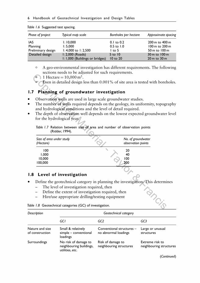
Table 1.6 Suggested test spacing.
Phase of project Typical map scale Boreholes per hectare Approximate spacing
IAS 1: 10,000 0.1 to 0.2 200 m to 400 mPlanning 1: 5,000 0.5 to 1.0 100 m to 200 mPreliminary design 1: 4,000 to 1: 2,500 1 to 5 50 m to 100 mDetailed design 1: 2,000 (Roads) 5 to 10 30 m to 100 m
1: 1,000 (Buildings or bridges) 10 to 20 20 m to 30 m
◦ A geo-environmental investigation has different requirements. The followingsections needs to be adjusted for such requirements.
◦ 1 Hectare = 10,000 m2.◦ Even in detailed design less than 0.001% of site area is tested with boreholes.
1.7 Planning of groundwater investigation
• Observation wells are used in large scale groundwater studies.• The number of wells required depends on the geology, its uniformity, topography
and hydrological conditions and the level of detail required.• The depth of observation well depends on the lowest expected groundwater level
for the hydrological year.
Table 1.7 Relation between size of area and number of observation points(Ridder, 1994).
Size of area under study No. of groundwater(Hectare) observation points
100 201,000 40
10,000 100100,000 200
1.8 Level of investigation
• Define the geotechnical category in planning the investigation. This determines– The level of investigation required, then– Define the extent of investigation required, then– Hire/use appropriate drilling/testing equipment
Table 1.8 Geotechnical categories (GC) of investigation.
Description Geotechnical category
GC1 GC2 GC3
Nature and sizeof construction
Small & relativelysimple – conventionalloadings
Conventional structures –no abnormal loadings
Large or unusualstructures
Surroundings No risk of damage toneighbouring buildings,utilities, etc.
Risk of damage toneighbouring structures
Extreme risk toneighbouring structures
(Continued)
Copyrighted
◦Copyrighted
◦ 1 HectareCopyrighted
1 Hectare◦
Copyrighted
◦ Even in detailed design less than 0.001% of site area is tested with boreholes.Copyrighted
Even in detailed design less than 0.001% of site area is tested with boreholes.
1.7 Planning of groundwater investigation
Copyrighted
1.7 Planning of groundwater investigation
Observation wells are used in large scale groundwater studies.
Copyrighted
Observation wells are used in large scale groundwater studies.The number of wells required depends on the geology, its uniformity, topography
Copyrighted The number of wells required depends on the geology, its uniformity, topographyand hydrological conditions and the level of detail required.
Copyrighted and hydrological conditions and the level of detail required.The depth of observation well depends on the lowest expected groundwater level
Copyrighted The depth of observation well depends on the lowest expected groundwater levelfor the hydrological year.
Copyrighted for the hydrological year.Material
for the hydrological year.Material
for the hydrological year.
Relation between size of area and number of observation points
Material
Relation between size of area and number of observation points
Material
Material - Taylor 200
Taylor 200
Taylor & Define the geotechnical category in planning the investigation. This determines& Define the geotechnical category in planning the investigation. This determinesFrancis
Define the geotechnical category in planning the investigation. This determinesFrancis
Define the geotechnical category in planning the investigation. This determinesFrancis
Site investigation 7
Table 1.8 (Continued)
Description Geotechnical category
GC1 GC2 GC3
Ground Straightforward. Does Routine procedures for Specialist testingconditions not apply to refuse, field and laboratory
uncompacted fill, loose testingor highly compressiblesoils
Ground waterconditions
No excavation belowwater table required
Below water table. Lastingdamage cannot be causedwithout prior warning
Extremely permeablelayers
Seismicity Non-Seismic Low seismicity High seismic areas
Capital cost <$1.0 Million(Aust. – 2013)
>$50 Milion(Aust. – 2013)
SI Cost as % ofcapital cost
0.1%–0.5%or $1,000 (Aust. min)
0.25%–1% 0.5%–2%or $100,000 (Aust. min)
Type of study Qualitative Quantitative geotechnical Two stage investigationinvestigation may studies requiredbe adequate
Minimum levelof expertise
Staff under supervisionby an experiencedGeotechnical specialist
Experienced GeotechnicalEngineer/EngineeringGeologist
Geotechnical Engineerwith relevant experienceto work with EngineeringGeologist and specialistGeotechnical/Tunnel/Geo – Environmentalengineer/Hydrogeologist/etc.
Examples ◦ Sign supports◦ Walls <2 m◦ Single or 2-storey
Buildings◦ Domestic buildings;
Light structures withcolumn loads up to250 kN or wallsloaded to 100 kN/m
◦ Minor roads
◦ Light – medium Industrial& Commercial buildings
◦ Major roads◦ Roads >1 km◦ Small/medium Bridges◦ Rail lines◦ Alluvial areas◦ Water nearby
◦ Dams◦ Hydraulic structures◦ Tunnels◦ Ports◦ Large bridges & build-ings◦ Heavy machinery
Foundations◦ Offshore platforms◦ Deep basements◦ Silos
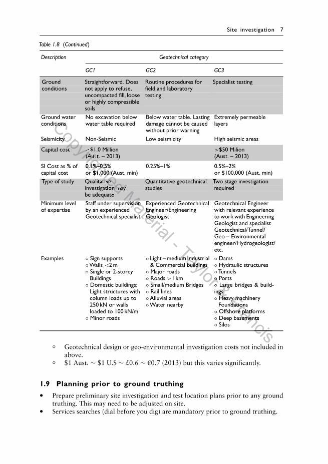
◦ Geotechnical design or geo-environmental investigation costs not included inabove.
◦ $1 Aust. ∼ $1 U.S ∼ £0.6 ∼ a0.7 (2013) but this varies significantly.
1.9 Planning prior to ground truthing
• Prepare preliminary site investigation and test location plans prior to any groundtruthing. This may need to be adjusted on site.
• Services searches (dial before you dig) are mandatory prior to ground truthing.
Copyrighted
conditionsCopyrighted
conditions
Seismicity Non-Seismic Low seismicity High seismic areas
Copyrighted
Seismicity Non-Seismic Low seismicity High seismic areas
Copyrighted
Capital cost
Copyrighted
Capital cost <
Copyrighted
<$1.0 Million
Copyrighted
$1.0 Million(Aust. – 2013)
Copyrighted
(Aust. – 2013)
0.1%–0.5%
Copyrighted 0.1%–0.5%or $1,000 (Aust. min)
Copyrighted or $1,000 (Aust. min)
Copyrighted Qualitative
Copyrighted Qualitative
Copyrighted investigation may
Copyrighted investigation may
Copyrighted be adequate
Copyrighted be adequate Material
Material
Material
Staff under supervisionMaterial
Staff under supervision
Geotechnical specialist
Material Geotechnical specialist
Experienced GeotechnicalMaterial
Experienced GeotechnicalEngineer/Engineering
Material
Engineer/EngineeringGeologist
Material Geologist
- Taylor Light – medium Industrial
Taylor Light – medium Industrial& Commercial buildings
Taylor & Commercial buildings
Small/medium Bridges
Taylor Small/medium Bridges
◦
Taylor ◦◦
Taylor ◦ Ports
Taylor Ports◦
Taylor ◦& Large bridges & build-& Large bridges & build-
ings& ingsHeavy machinery& Heavy machineryFrancis
Heavy machineryFrancis
Heavy machineryFoundationsFrancis
FoundationsFrancisOffshore platforms
FrancisOffshore platformsDeep basements
FrancisDeep basements
Francis
Francis
8 Handbook of Geotechnical Investigation and Design Tables
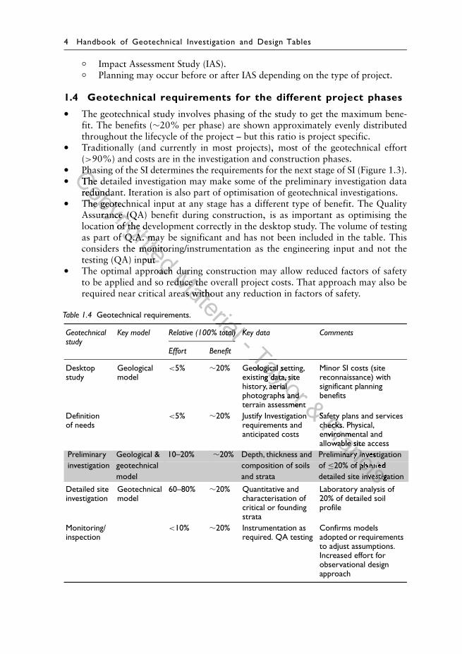
• Further services location tests and/or isolations may be required on site. Typicallymandatory for any service within 3 m of the test location.
• Obtain utility services plans both above and below the ground are required.For example, an above ground electrical line may dictate either the proximityof the borehole, or a drilling rig/with a certain mast height and permission fromthe electrical safety authority before proceeding.
• The planning should allow for any physical obstructions such as coring of aconcrete slab, and its subsequent repair after coring.
Table 1.9 Planning checklist.
Type Items
Informative Timing. Authority to proceed. Inform all relevant stakeholders.Environmental approvals. Access. Site history. Physical obstructions.Positional accuracy requirements (taped, GPS, survey)
Site specific safety plans Traffic Controls. Services checks. Possible shut down of nearbyoperational plant. Isolations required. Site specific inductions
SI Management Checklists. Coordination and contacts. GPS or map locator. Aims ofinvestigation understood by all. Logging templates. Depth andsampling requirements. Sampling bags, core trays, permanent markers.Budget limits where client needs to be advised if additional SI required.Repair or sealing of test locations.
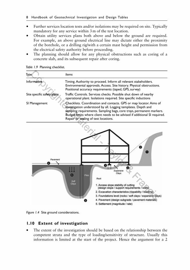
Figure 1.4 Site ground considerations.
1.10 Extent of investigation
• The extent of the investigation should be based on the relationship between thecompetent strata and the type of loading/sensitivity of structure. Usually thisinformation is limited at the start of the project. Hence the argument for a 2
Copyrighted
Copyrighted
TypeCopyrighted
TypeCopyrighted
Informative
Copyrighted
Informative
Site specific safety plans Traffic Controls. Services checks. Possible shut down of nearby
Copyrighted
Site specific safety plans Traffic Controls. Services checks. Possible shut down of nearbyoperational plant. Isolations required. Site specific inductions
Copyrighted operational plant. Isolations required. Site specific inductionsChecklists. Coordination and contacts. GPS or map locator. Aims of
Copyrighted Checklists. Coordination and contacts. GPS or map locator. Aims ofinvestigation understood by all. Logging templates. Depth and
Copyrighted investigation understood by all. Logging templates. Depth andsampling requirements. Sampling bags, core trays, permanent markers.
Copyrighted sampling requirements. Sampling bags, core trays, permanent markers.Budget limits where client needs to be advised if additional SI required.
Copyrighted Budget limits where client needs to be advised if additional SI required.Material
sampling requirements. Sampling bags, core trays, permanent markers.Material
sampling requirements. Sampling bags, core trays, permanent markers.Budget limits where client needs to be advised if additional SI required.Material
Budget limits where client needs to be advised if additional SI required.Repair or sealing of test locations.Material
Repair or sealing of test locations.Material
Material - Taylor & Francis
Site investigation 9
phased investigation approach for all but small (GC1) projects. For example in apiled foundation design.
– The preliminary investigation or existing nearby data (if available) determinesthe likely founding level
– And the detailed investigation provides quantitative assessment, targetingtesting at that founding level
• The load considerations should determine the depth of the investigation– >1.5 × width (B) of loaded area for square footings (pressure bulb ∼0.2q
where q = applied load)– >3.0 × width (B) of loaded area for strip footings (pressure bulb ∼0.2q)– However the loading/width is often not known prior to the investigation, and
one should assess to a “competent’’ strata• The ground considerations intersected should also determine the depth of the
investigation as the ground truthing must provide– Information of the competent strata, and probe below any compressible layer– Spacing dependent on uniformity of sub-surface conditions and type of
structure
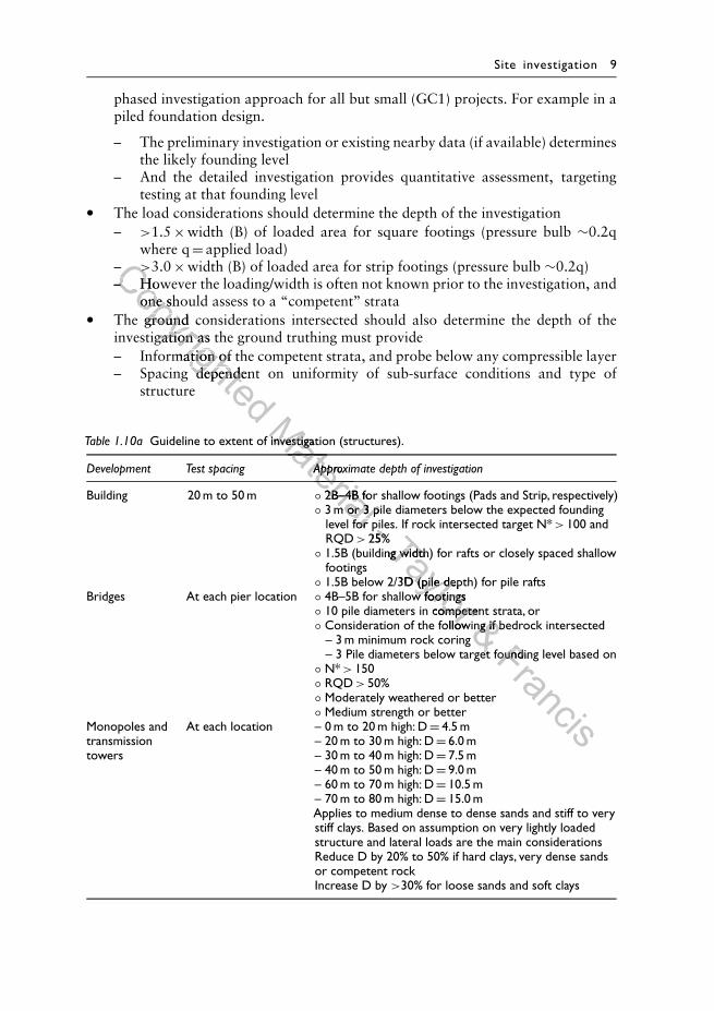
Table 1.10a Guideline to extent of investigation (structures).
Development Test spacing Approximate depth of investigation
Building 20 m to 50 m ◦ 2B–4B for shallow footings (Pads and Strip, respectively)◦ 3 m or 3 pile diameters below the expected founding
level for piles. If rock intersected target N* > 100 andRQD > 25%
◦ 1.5B (building width) for rafts or closely spaced shallowfootings
◦ 1.5B below 2/3D (pile depth) for pile raftsBridges At each pier location ◦ 4B–5B for shallow footings
◦ 10 pile diameters in competent strata, or◦ Consideration of the following if bedrock intersected
– 3 m minimum rock coring– 3 Pile diameters below target founding level based on
◦ N* > 150◦ RQD > 50%◦ Moderately weathered or better◦ Medium strength or better
Monopoles andtransmissiontowers
At each location – 0 m to 20 m high: D = 4.5 m– 20 m to 30 m high: D = 6.0 m– 30 m to 40 m high: D = 7.5 m– 40 m to 50 m high: D = 9.0 m– 60 m to 70 m high: D = 10.5 m– 70 m to 80 m high: D = 15.0 mApplies to medium dense to dense sands and stiff to verystiff clays. Based on assumption on very lightly loadedstructure and lateral loads are the main considerationsReduce D by 20% to 50% if hard clays, very dense sandsor competent rockIncrease D by >30% for loose sands and soft clays
Copyrighted
>Copyrighted
>
– However the loading/width is often not known prior to the investigation, andCopyrighted
– However the loading/width is often not known prior to the investigation, andone should assess to a “competent’’ strata
Copyrighted
one should assess to a “competent’’ strataThe ground considerations intersected should also determine the depth of the
Copyrighted
The ground considerations intersected should also determine the depth of theinvestigation as the ground truthing must provide
Copyrighted
investigation as the ground truthing must provide– Information of the competent strata, and probe below any compressible layer
Copyrighted
– Information of the competent strata, and probe below any compressible layer– Spacing dependent on uniformity of sub-surface conditions and type of
Copyrighted – Spacing dependent on uniformity of sub-surface conditions and type of
Material
Guideline to extent of investigation (structures).Material
Guideline to extent of investigation (structures).Material
Approximate depth of investigation
Material Approximate depth of investigation
Material 2B–4B for shallow footings (Pads and Strip, respectively)
Material 2B–4B for shallow footings (Pads and Strip, respectively)3 m or 3 pile diameters below the expected founding
Material 3 m or 3 pile diameters below the expected foundinglevel for piles. If rock intersected target N*
Material level for piles. If rock intersected target N*- level for piles. If rock intersected target N*- level for piles. If rock intersected target N*25%- 25%Taylor
1.5B (building width) for rafts or closely spaced shallowTaylor
1.5B (building width) for rafts or closely spaced shallowTaylor 1.5B below 2/3D (pile depth) for pile rafts
Taylor 1.5B below 2/3D (pile depth) for pile rafts4B–5B for shallow footings
Taylor 4B–5B for shallow footings10 pile diameters in competent strata, or
Taylor 10 pile diameters in competent strata, orConsideration of the following if bedrock intersected
Taylor Consideration of the following if bedrock intersected& 10 pile diameters in competent strata, or& 10 pile diameters in competent strata, orConsideration of the following if bedrock intersected& Consideration of the following if bedrock intersected– 3 m minimum rock coring
& – 3 m minimum rock coring– 3 Pile diameters below target founding level based on
& – 3 Pile diameters below target founding level based onFrancis
– 3 Pile diameters below target founding level based onFrancis
– 3 Pile diameters below target founding level based on
10 Handbook of Geotechnical Investigation and Design Tables
◦ N∗ Inferred SPT value◦ RQD – Rock Quality Designation◦ H – Height of slope◦ D – Depth of investigation◦ Ensure boulders or layers of cemented soils are not mistaken for bedrock by
penetrating approximately 3 m into bedrock.◦ Where water bearing sand strata, there is a need to seal exploratory boreholes
especially in dams, tunnels and environmental studies.◦ Any destructive tests on operational surfaces (travelled lane of roadways)
needs repair◦ In soft/compressible layers and fills, the SI may need to extend BHs in all cases
to the full depth of that layer.◦ Samples/testing every 1.5 m spacing or changes in strata.◦ Obtain undisturbed samples in clays and carry out SPT tests in granular
material.◦ Use of the structure also determines whether a GC2 or GC3 investigation
applies. For example, a building for a nuclear facility (GC3) requires a closerspacing than for an industrial (GC2) building.
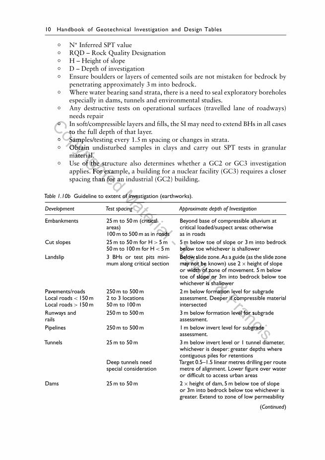
Table 1.10b Guideline to extent of investigation (earthworks).
Development Test spacing Approximate depth of Investigation
Embankments 25 m to 50 m (criticalareas)100 m to 500 m as in roads
Beyond base of compressible alluvium atcritical loaded/suspect areas: otherwiseas in roads
Cut slopes 25 m to 50 m for H > 5 m50 m to 100 m for H < 5 m
5 m below toe of slope or 3 m into bedrockbelow toe whichever is shallower
Landslip 3 BHs or test pits mini-mum along critical section
Below slide zone.As a guide (as the slide zonemay not be known) use 2 × height of slopeor width of zone of movement. 5 m belowtoe of slope or 3m into bedrock below toewhichever is shallower
Pavements/roadsLocal roads < 150 mLocal roads > 150 m
250 m to 500 m2 to 3 locations50 m to 100 m
2 m below formation level for subgradeassessment. Deeper if compressible materialintersected
Runways andrails
250 m to 500 m 3 m below formation level for subgradeassessment.
Pipelines 250 m to 500 m 1 m below invert level for subgradeassessment.
Tunnels 25 m to 50 m
Deep tunnels needspecial consideration
3 m below invert level or 1 tunnel diameter,whichever is deeper: greater depths wherecontiguous piles for retentionsTarget 0.5–1.5 linear metres drilling per routemetre of alignment. Lower figure over wateror difficult to access urban areas
Dams 25 m to 50 m 2 × height of dam, 5 m below toe of slopeor 3m into bedrock below toe whichever isgreater. Extend to zone of low permeability
(Continued)
Copyrighted
◦Copyrighted
◦ In soft/compressible layers and fills, the SI may need to extend BHs in all casesCopyrighted
In soft/compressible layers and fills, the SI may need to extend BHs in all casesto the full depth of that layer.
Copyrighted
to the full depth of that layer.◦
Copyrighted
◦ Samples/testing every 1.5 m spacing or changes in strata.
Copyrighted
Samples/testing every 1.5 m spacing or changes in strata.Obtain undisturbed samples in clays and carry out SPT tests in granular
Copyrighted
Obtain undisturbed samples in clays and carry out SPT tests in granularmaterial.
Copyrighted
material.Use of the structure also determines whether a GC2 or GC3 investigation
Copyrighted Use of the structure also determines whether a GC2 or GC3 investigationapplies. For example, a building for a nuclear facility (GC3) requires a closer
Copyrighted applies. For example, a building for a nuclear facility (GC3) requires a closerspacing than for an industrial (GC2) building.
Copyrighted spacing than for an industrial (GC2) building.
Guideline to extent of investigation (earthworks).
Copyrighted Guideline to extent of investigation (earthworks).Material
Guideline to extent of investigation (earthworks).Material
Guideline to extent of investigation (earthworks).Material
Test spacing
Material
Test spacing
Material Embankments 25 m to 50 m (critical
Material Embankments 25 m to 50 m (critical
100 m to 500 m as in roads
Material 100 m to 500 m as in roads5 m
Material 5 m- Taylor
5 m below toe of slope or 3 m into bedrockTaylor
5 m below toe of slope or 3 m into bedrockbelow toe whichever is shallowerTaylor
below toe whichever is shallowerBelow slide zone.As a guide (as the slide zoneTaylor
Below slide zone.As a guide (as the slide zonemay not be known) use 2
Taylor may not be known) use 2or width of zone of movement. 5 m below
Taylor or width of zone of movement. 5 m belowtoe of slope or 3m into bedrock below toe
Taylor toe of slope or 3m into bedrock below toewhichever is shallower
Taylor whichever is shallower& whichever is shallower& whichever is shallower& 2 m below formation level for subgrade
& 2 m below formation level for subgradeassessment. Deeper if compressible material
& assessment. Deeper if compressible materialFrancis
2 m below formation level for subgradeFrancis
2 m below formation level for subgradeassessment. Deeper if compressible materialFrancis
assessment. Deeper if compressible material
250 m to 500 m 3 m below formation level for subgrade
Francis250 m to 500 m 3 m below formation level for subgrade
Pipelines 250 m to 500 m 1 m below invert level for subgrade
FrancisPipelines 250 m to 500 m 1 m below invert level for subgrade
3 m below invert level or 1 tunnel diameter,
Francis3 m below invert level or 1 tunnel diameter,
Site investigation 11
Table 1.10b (Continued)
Development Test spacing Approximate depth of Investigation
Canals 100 m to 200 m 3 m minimum below invert level or to a zone oflow permeability
Culverts<20 m width20 m–40 m>40 m width
1 BoreholeOne at each endOne at each end and 1 inthe middle with maximumspacing of 20 m betweenboreholes
2B–4B but below base of compressible layer
Car parks 2 Bhs for <50 parks3 Bhs for 50–1004 Bhs for 100–2005 Bhs for 200–4006 Bhs for >400 parks
2 m below formation level
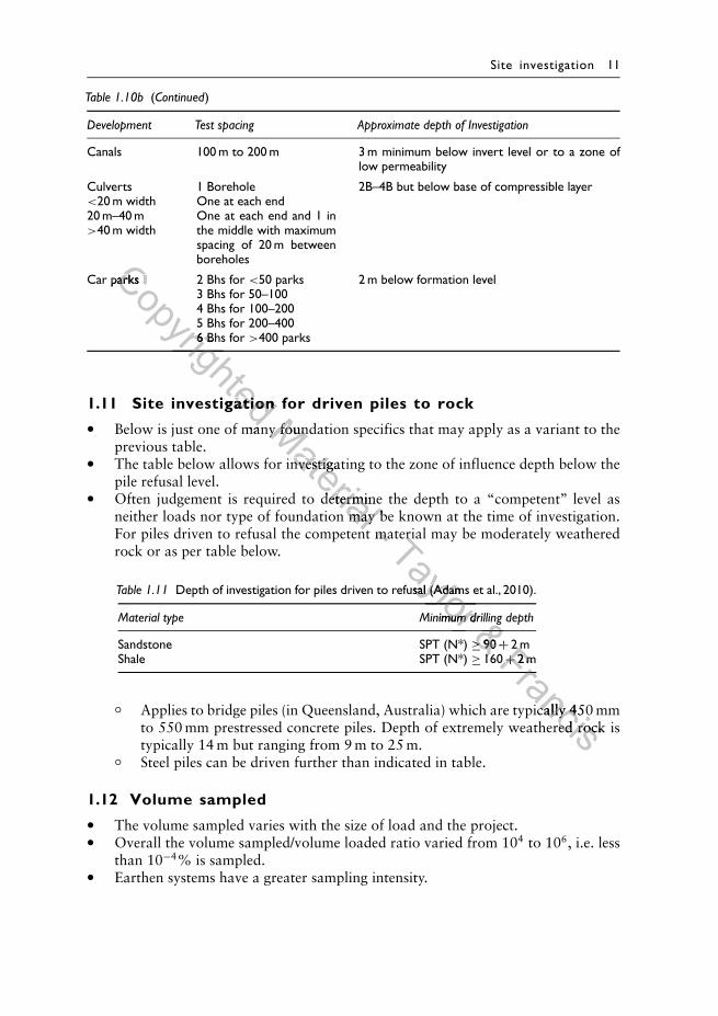
1.11 Site investigation for driven piles to rock
• Below is just one of many foundation specifics that may apply as a variant to theprevious table.
• The table below allows for investigating to the zone of influence depth below thepile refusal level.
• Often judgement is required to determine the depth to a “competent’’ level asneither loads nor type of foundation may be known at the time of investigation.For piles driven to refusal the competent material may be moderately weatheredrock or as per table below.
Table 1.11 Depth of investigation for piles driven to refusal (Adams et al., 2010).
Material type Minimum drilling depth
Sandstone SPT (N*) ≥ 90 + 2 mShale SPT (N*) ≥ 160 + 2 m
◦ Applies to bridge piles (in Queensland, Australia) which are typically 450 mmto 550 mm prestressed concrete piles. Depth of extremely weathered rock istypically 14 m but ranging from 9 m to 25 m.
◦ Steel piles can be driven further than indicated in table.
1.12 Volume sampled
• The volume sampled varies with the size of load and the project.• Overall the volume sampled/volume loaded ratio varied from 104 to 106, i.e. less
than 10−4% is sampled.• Earthen systems have a greater sampling intensity.
Copyrighted
Car parks 2 Bhs forCopyrighted
Car parks 2 Bhs for
5 Bhs for 200–400
Copyrighted
5 Bhs for 200–4006 Bhs for
Copyrighted
6 Bhs for
Copyrighted Site investigation for driven piles to rock
Copyrighted Site investigation for driven piles to rock
Below is just one of many foundation specifics that may apply as a variant to the
Copyrighted Below is just one of many foundation specifics that may apply as a variant to theMaterial
Below is just one of many foundation specifics that may apply as a variant to theMaterial
Below is just one of many foundation specifics that may apply as a variant to the
The table below allows for investigating to the zone of influence depth below the
Material The table below allows for investigating to the zone of influence depth below the
Often judgement is required to determine the depth to a “competent’’ level as
Material Often judgement is required to determine the depth to a “competent’’ level asneither loads nor type of foundation may be known at the time of investigation.
Material neither loads nor type of foundation may be known at the time of investigation.For piles driven to refusal the competent material may be moderately weathered
Material For piles driven to refusal the competent material may be moderately weathered- For piles driven to refusal the competent material may be moderately weathered- For piles driven to refusal the competent material may be moderately weatheredTaylor
For piles driven to refusal the competent material may be moderately weatheredTaylor
For piles driven to refusal the competent material may be moderately weathered
Depth of investigation for piles driven to refusal (Adams et al., 2010).
Taylor Depth of investigation for piles driven to refusal (Adams et al., 2010).
Taylor Minimum drilling depth
Taylor Minimum drilling depth
Taylor & Minimum drilling depth& Minimum drilling depth& ≥& ≥ 90
& 90 +& +160
& 160Francis
2 mFrancis
2 m+Francis
+ 2 mFrancis
2 mFrancisApplies to bridge piles (in Queensland, Australia) which are typically 450 mm
FrancisApplies to bridge piles (in Queensland, Australia) which are typically 450 mm
Francisto 550 mm prestressed concrete piles. Depth of extremely weathered rock is
Francisto 550 mm prestressed concrete piles. Depth of extremely weathered rock is

12 Handbook of Geotechnical Investigation and Design Tables
Table 1.12 Relative volume sampled (simplified from graph in Kulhawy, 1992)
Type of development Typical volume sampled Typical volume loaded Relative volume sampled/volume loaded
Buildings 0.4 m3 2 × 10⁴ m3 2 × 10⁻⁵
Concrete dam 10 m3 5 × 10⁵ m3 2 × 10⁻⁵
Earth dam 100 m3 5 × 10⁶ m3 2 × 10⁻⁵
1.13 Relative risk ranking of developments
• The risk is very project and site specific, i.e. varies from project to project, locationand its size.
• The investigation should therefore theoretically reflect overall risk.• Geotechnical Category (GC) rating as per Table 1.8 can also be assessed by the
development risk.• The variability or unknown factors has the highest risk rank (F), while certainty
has the least risk rank (A)◦ Projects with significant environmental and water considerations should be
treated as a higher risk development◦ Developments with uncertainty of loading are also considered higher risk,
although higher loading partial factors of safety usually apply• The table is a guide in assessing the likely risk factor for the extent and emphasis
of the geotechnical data requirements.
Table 1.13 Risk categories.
Development Risk factor considerations
Loading Environment Water Ground Economic Life Overall
Offshore platforms F F F F F E
High
Earth dam > 15 m E E E E E F
GC3
Tunnels E E E E E FPower stations E E D D F EPorts & coastal developments F E F F E ENuclear, chemical, & D F D D D Fbiological complexes
Concrete dams D D E E E EContaminated land B F D E C FTailing dams D E E E D DMining E D D D D DHydraulic structures D D E E D DBuildings storing D E C C C E
Serioushazardous goods
GC3Landfills B D D D D ESub-stations D D C C D ERail embankments D C D D D EEarth dams 5 m–15 m D D D D D DCofferdams E D E E C DCuttings/walls >7 m D C D D D DRailway bridges D C C C D DPetrol stations C D C C C D
(Continued)
Copyrighted
The risk is very project and site specific, i.e. varies from project to project, locationCopyrighted
The risk is very project and site specific, i.e. varies from project to project, locationand its size.Copyrighted
and its size.The investigation should therefore theoretically reflect overall risk.
Copyrighted
The investigation should therefore theoretically reflect overall risk.Geotechnical Category (GC) rating as per Table 1.8 can also be assessed by the
Copyrighted
Geotechnical Category (GC) rating as per Table 1.8 can also be assessed by thedevelopment risk.
Copyrighted
development risk.The variability or unknown factors has the highest risk rank (F), while certainty
Copyrighted
The variability or unknown factors has the highest risk rank (F), while certaintyhas the least risk rank (A)
Copyrighted has the least risk rank (A)
Projects with significant environmental and water considerations should be
Copyrighted Projects with significant environmental and water considerations should betreated as a higher risk development
Copyrighted treated as a higher risk developmentDevelopments with uncertainty of loading are also considered higher risk,
Copyrighted Developments with uncertainty of loading are also considered higher risk,Material
Developments with uncertainty of loading are also considered higher risk,Material
Developments with uncertainty of loading are also considered higher risk,although higher loading partial factors of safety usually apply
Material
although higher loading partial factors of safety usually applyThe table is a guide in assessing the likely risk factor for the extent and emphasis
Material
The table is a guide in assessing the likely risk factor for the extent and emphasisof the geotechnical data requirements.
Material of the geotechnical data requirements.
Material - Taylor
Risk factor considerationsTaylor
Risk factor considerationsTaylor
Taylor Loading Environment Water Ground Economic Life Overall
Taylor Loading Environment Water Ground Economic Life Overall
Taylor F F F E
Taylor F F F EE E E F
Taylor E E E FE E E F
Taylor E E E FD D F E
Taylor D D F E& E E E F& E E E FD D F E& D D F EF F E E
& F F E EFrancis
F F E EFrancis
F F E ED D D FFrancis
D D D F
D D E E E E
FrancisD D E E E E
Francis
FrancisF
FrancisF
Francis
Francis
Site investigation 13
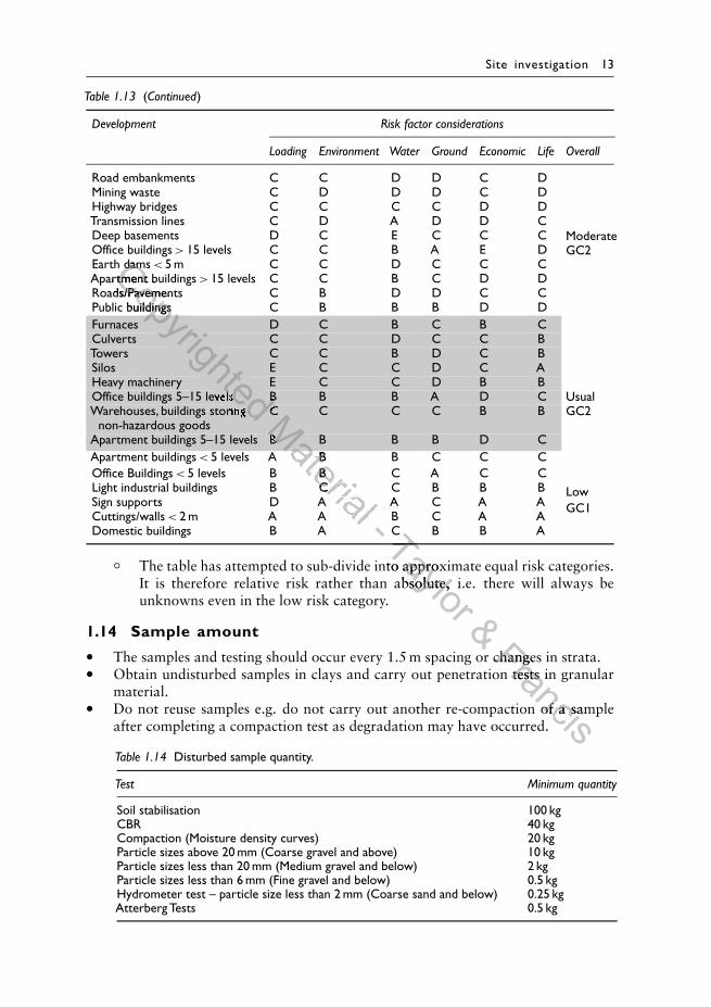
Table 1.13 (Continued)
Development Risk factor considerations
Loading Environment Water Ground Economic Life Overall
Road embankments C C D D C D
Moderate
Mining waste C D D D C D
GC2
Highway bridges C C C C D DTransmission lines C D A D D CDeep basements D C E C C COffice buildings > 15 levels C C B A E DEarth dams < 5 m C C D C C CApartment buildings > 15 levels C C B C D DRoads/Pavements C B D D C CPublic buildings C B B B D DFurnaces D C B C B C
Usual
Culverts C C D C C B
GC2
Towers C C B D C BSilos E C C D C AHeavy machinery E C C D B BOffice buildings 5–15 levels B B B A D CWarehouses, buildings storing C C C C B B
non-hazardous goodsApartment buildings 5–15 levels B B B B D CApartment buildings < 5 levels A B B C C C
LowOffice Buildings < 5 levels B B C A C C
GC1
Light industrial buildings B C C B B BSign supports D A A C A ACuttings/walls < 2 m A A B C A ADomestic buildings B A C B B A
◦ The table has attempted to sub-divide into approximate equal risk categories.It is therefore relative risk rather than absolute, i.e. there will always beunknowns even in the low risk category.
1.14 Sample amount
• The samples and testing should occur every 1.5 m spacing or changes in strata.• Obtain undisturbed samples in clays and carry out penetration tests in granular
material.• Do not reuse samples e.g. do not carry out another re-compaction of a sample
after completing a compaction test as degradation may have occurred.
Table 1.14 Disturbed sample quantity.
Test Minimum quantity
Soil stabilisation 100 kgCBR 40 kgCompaction (Moisture density curves) 20 kgParticle sizes above 20 mm (Coarse gravel and above) 10 kgParticle sizes less than 20 mm (Medium gravel and below) 2 kgParticle sizes less than 6 mm (Fine gravel and below) 0.5 kgHydrometer test – particle size less than 2 mm (Coarse sand and below) 0.25 kgAtterberg Tests 0.5 kg
Copyrighted
Earth damsCopyrighted
Earth damsApartment buildingsCopyrighted
Apartment buildingsRoads/PavementsCopyrighted
Roads/PavementsPublic buildings
Copyrighted
Public buildings
Copyrighted
Copyrighted
Copyrighted
Copyrighted
Copyrighted
Copyrighted
Copyrighted Office buildings 5–15 levels
Copyrighted Office buildings 5–15 levels
Copyrighted B
Copyrighted B
Copyrighted Warehouses, buildings storing
Copyrighted Warehouses, buildings storing
Copyrighted C
Copyrighted C
Copyrighted Material
Material
Material
Material
BMaterial
BMaterial
5 levels A B B C C C
Material
5 levels A B B C C C5 levels B B C A C C
Material 5 levels B B C A C C
Light industrial buildings B C C B B B
Material Light industrial buildings B C C B B BSign supports D A A C A A
Material Sign supports D A A C A A2 m A A B C A A
Material 2 m A A B C A A- Taylor
C B B ATaylor
C B B ATaylor The table has attempted to sub-divide into approximate equal risk categories.
Taylor The table has attempted to sub-divide into approximate equal risk categories.It is therefore relative risk rather than absolute, i.e. there will always be
Taylor It is therefore relative risk rather than absolute, i.e. there will always be
& The samples and testing should occur every 1.5 m spacing or changes in strata.
& The samples and testing should occur every 1.5 m spacing or changes in strata.Francis
The samples and testing should occur every 1.5 m spacing or changes in strata.Francis
The samples and testing should occur every 1.5 m spacing or changes in strata.Obtain undisturbed samples in clays and carry out penetration tests in granular
FrancisObtain undisturbed samples in clays and carry out penetration tests in granular
FrancisDo not reuse samples e.g. do not carry out another re-compaction of a sample
FrancisDo not reuse samples e.g. do not carry out another re-compaction of a sample
14 Handbook of Geotechnical Investigation and Design Tables
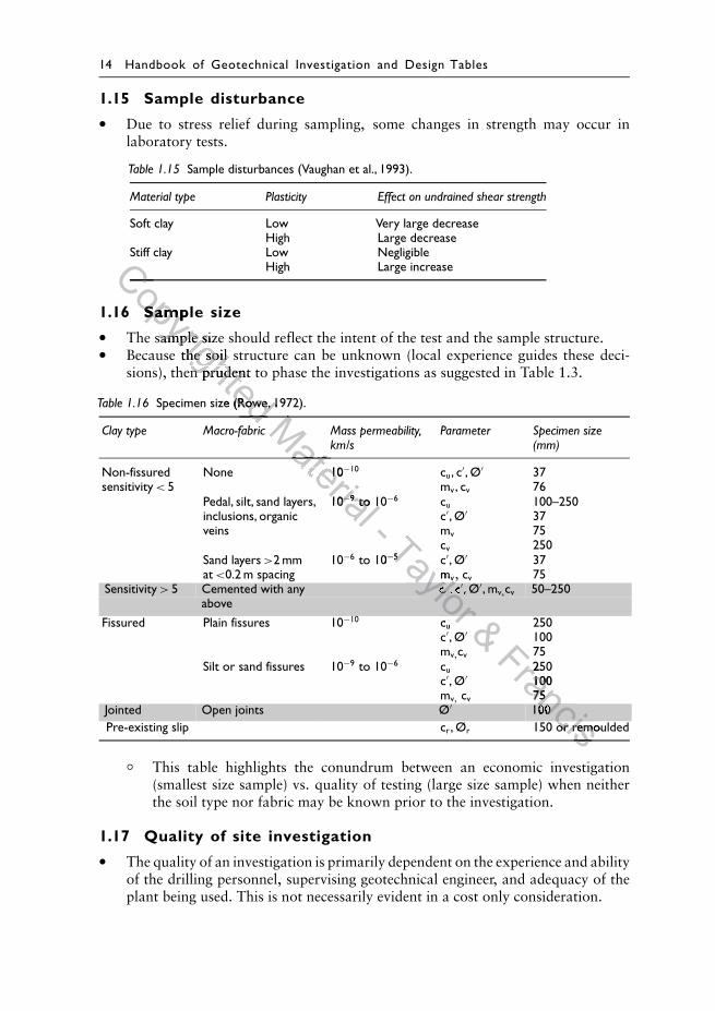
1.15 Sample disturbance
• Due to stress relief during sampling, some changes in strength may occur inlaboratory tests.
Table 1.15 Sample disturbances (Vaughan et al., 1993).
Material type Plasticity Effect on undrained shear strength
Soft clay Low Very large decreaseHigh Large decrease
Stiff clay Low NegligibleHigh Large increase
1.16 Sample size
• The sample size should reflect the intent of the test and the sample structure.• Because the soil structure can be unknown (local experience guides these deci-
sions), then prudent to phase the investigations as suggested in Table 1.3.
Table 1.16 Specimen size (Rowe, 1972).
Clay type Macro-fabric Mass permeability,km/s
Parameter Specimen size(mm)
Non-fissuredsensitivity < 5
None 10−10 cu, c′, Ø′mv, cv
3776
Pedal, silt, sand layers,inclusions, organicveins
10−9 to 10−6 cuc′, Ø′mvcv
100–2503775250
Sand layers >2 mmat <0.2 m spacing
10−6 to 10−5 c′, Ø′mv, cv
3775
Sensitivity > 5 Cemented with any cu, c′, Ø′, mv,cv 50–250above
Fissured Plain fissures 10−10 cuc′, Ø′mv,cv
25010075
Silt or sand fissures 10−9 to 10−6 cuc′, Ø′mv, cv
25010075
Jointed Open joints Ø′ 100Pre-existing slip cr, Ør 150 or remoulded
◦ This table highlights the conundrum between an economic investigation(smallest size sample) vs. quality of testing (large size sample) when neitherthe soil type nor fabric may be known prior to the investigation.
1.17 Quality of site investigation
• The quality of an investigation is primarily dependent on the experience and abilityof the drilling personnel, supervising geotechnical engineer, and adequacy of theplant being used. This is not necessarily evident in a cost only consideration.
Copyrighted
Copyrighted
Sample size
Copyrighted
Sample size
The sample size should reflect the intent of the test and the sample structure.
Copyrighted
The sample size should reflect the intent of the test and the sample structure.Because the soil structure can be unknown (local experience guides these deci-
Copyrighted
Because the soil structure can be unknown (local experience guides these deci-sions), then prudent to phase the investigations as suggested in Table 1.3.
Copyrighted sions), then prudent to phase the investigations as suggested in Table 1.3.
Specimen size (Rowe, 1972).
Copyrighted Specimen size (Rowe, 1972).
Copyrighted Clay type Macro-fabric
Copyrighted Clay type Macro-fabricMaterial
Material
Material None 10
Material None 10
10
Material 10−
Material −9
Material 9 to 10
Material to 10
- Taylor
to 10Taylor
to 10−Taylor
−5Taylor
5
m
Taylor mv
Taylor v
Taylor c
Taylor cu
Taylor u, c
Taylor , c′
Taylor ′, Ø
Taylor , Ø
Taylor c
Taylor cu
Taylor u, Ø
Taylor , Ø & Francis
250Francis
250Francis
100
Francis10075
Francis75
Francis100
Francis100
Francis150 or remoulded
Francis150 or remoulded
Francis
Site investigation 15
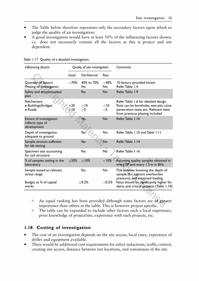
• The Table below therefore represents only the secondary factors upon which tojudge the quality of an investigation.
• A good investigation would have at least 50% of the influencing factors shown,i.e. does not necessarily contain all the factors as this is project and sitedependent.
Table 1.17 Quality of a detailed investigation.
Influencing factors Quality of site investigation Comments
Good Fair/Normal Poor
Quantity of factors >70% 40% to 70% <40% 10 factors provided hereinPhasing of investigation Yes No Refer Table 1.4Safety and environmental Yes No Refer Table 1.9plan
Test/hectare Refer Table 1.6 for detailed design.• Buildings/bridges >20 ≥10 <10 Tests can be boreholes, test pits, cone• Roads >10 ≥5 <5 penetration tests, etc. Relevant tests
from previous phasing includedExtent of investigation Yes No Refer Table 1.10reflects type ofdevelopment
Depth of investigationadequate to ground
Yes No Refer Table 1.10 and Table 1.11
Sample amount sufficient Yes No Refer Table 1.14for lab testing
Specimen size accountingfor soil structure
Yes No Refer Table 1.16
% of samples testing in the ≥20% ≥10% <10% Assuming quality samples obtained inlaboratory every TP and every 1.5 m in BHs
Sample tested at relevant Yes No This involves knowing the depth ofstress range sample (for current overburden
pressure), and expected loadingBudget as % of capitalworks
≥0.2% <0.2% Value should be significantly higher fordams, and critical projects (Table 1.14)
◦ An equal ranking has been provided although some factors are of greaterimportance than others in the table. This is however project specific.
◦ The table can be expanded to include other factors such a local experience,prior knowledge of project/site, experience with such projects, etc.
1.18 Costing of investigation
• The cost of an investigation depends on the site access, local rates, experience ofdriller and equipment available.
• There would be additional cost requirements for safety inductions, traffic control,creating site access, distance between test locations, and remoteness of the site.
Copyrighted
Copyrighted
Quantity of factors
Copyrighted
Quantity of factorsPhasing of investigation Yes No Refer Table 1.4
Copyrighted
Phasing of investigation Yes No Refer Table 1.4
Copyrighted
Safety and environmental
Copyrighted
Safety and environmental
>
Copyrighted >20
Copyrighted 20
>
Copyrighted >10
Copyrighted 10
Copyrighted Material
Material
Yes No Refer Table 1.10Material
Yes No Refer Table 1.10
Yes No Refer Table 1.10 and Table 1.11
Material Yes No Refer Table 1.10 and Table 1.11
Material Yes No Refer Table 1.14
Material Yes No Refer Table 1.14- - Yes No Refer Table 1.16- Yes No Refer Table 1.16Taylor
Yes No Refer Table 1.16Taylor
Yes No Refer Table 1.16Taylor
Taylor
Taylor
Taylor 10% Assuming quality samples obtained in
Taylor 10% Assuming quality samples obtained in
laboratory every TP and every 1.5 m in BHs
Taylor laboratory every TP and every 1.5 m in BHs
Sample tested at relevant Yes No This involves knowing the depth of
Taylor Sample tested at relevant Yes No This involves knowing the depth ofstress range sample (for current overburden
Taylor stress range sample (for current overburden& Sample tested at relevant Yes No This involves knowing the depth of& Sample tested at relevant Yes No This involves knowing the depth ofstress range sample (for current overburden& stress range sample (for current overburden
pressure), and expected loading& pressure), and expected loading
0.2% Value should be significantly higher for
& 0.2% Value should be significantly higher forFrancis
pressure), and expected loadingFrancis
pressure), and expected loading0.2% Value should be significantly higher forFrancis
0.2% Value should be significantly higher fordams, and critical projects (Table 1.14)
Francisdams, and critical projects (Table 1.14)
Francis
FrancisAn equal ranking has been provided although some factors are of greater
FrancisAn equal ranking has been provided although some factors are of greater
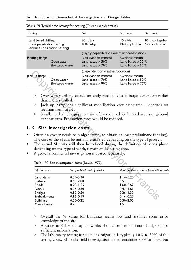
16 Handbook of Geotechnical Investigation and Design Tables
Table 1.18 Typical productivity for costing (Queensland Australia).
Drilling Soil Soft rock Hard rock
Land based drilling 20 m/day 15 m/day 10 m coring/dayCone penetration testing 100 m/day Not applicable Not applicable(excludes dissipation testing)
(Highly dependent on weather/tides/location)Floating barge Non-cyclonic months Cyclonic month
Open water Land based × 50% Land based × 30 %Sheltered water Land based × 70% Land based × 50 %
(Dependent on weather/Location)Jack up barge Non-cyclonic months Cyclonic month
Open water Land based × 70% Land based × 50%Sheltered water Land based × 90% Land based × 70%
◦ Over water drilling costed on daily rates as cost is barge dependent ratherthan metres drilled.
◦ Jack up barge has significant mobilisation cost associated – depends onlocation from source.
◦ Smaller or lighter equipment are often required for limited access or groundsupport sites. Production rates would be reduced.
1.19 Site investigation costs
• Often an owner needs to budget items (to obtain at least preliminary funding).The cost of the SI can be initially estimated depending on the type of project.
• The actual SI costs will then be refined during the definition of needs phasedepending on the type of work, terrain and existing data.
• A geo-environmental investigation is costed separately.
Table 1.19 Site investigation costs (Rowe, 1972).
Type of work % of capital cost of works % of earthworks and foundation costs
Earth dams 0.89–3.30 1.14–5.20Railways 0.60–2.00 3.5Roads 0.20–1.55 1.60–5.67Docks 0.23–0.50 0.42–1.67Bridges 0.12–0.50 0.26–1.30Embankments 0.12–0.19 0.16–0.20Buildings 0.05–0.22 0.50–2.00Overall mean 0.7 1.5
◦ Overall the % value for buildings seems low and assumes some priorknowledge of the site.
◦ A value of 0.2% of capital works should be the minimum budgeted forsufficient information.
◦ The laboratory testing for a site investigation is typically 10% to 20% of thetesting costs, while the field investigation is the remaining 80% to 90%, but
Copyrighted
Jack up barge Non-cyclonic months Cyclonic monthCopyrighted
Jack up barge Non-cyclonic months Cyclonic monthCopyrighted
Over water drilling costed on daily rates as cost is barge dependent rather
Copyrighted Over water drilling costed on daily rates as cost is barge dependent ratherthan metres drilled.
Copyrighted than metres drilled.Jack up barge has significant mobilisation cost associated – depends on
Copyrighted Jack up barge has significant mobilisation cost associated – depends onlocation from source.
Copyrighted location from source.Smaller or lighter equipment are often required for limited access or ground
Copyrighted Smaller or lighter equipment are often required for limited access or groundMaterial
Smaller or lighter equipment are often required for limited access or groundMaterial
Smaller or lighter equipment are often required for limited access or groundsupport sites. Production rates would be reduced.
Material
support sites. Production rates would be reduced.
Site investigation costs
Material Site investigation costs
Often an owner needs to budget items (to obtain at least preliminary funding).
Material Often an owner needs to budget items (to obtain at least preliminary funding).The cost of the SI can be initially estimated depending on the type of project.
Material The cost of the SI can be initially estimated depending on the type of project.- The cost of the SI can be initially estimated depending on the type of project.- The cost of the SI can be initially estimated depending on the type of project.The actual SI costs will then be refined during the definition of needs phase- The actual SI costs will then be refined during the definition of needs phaseTaylor
The actual SI costs will then be refined during the definition of needs phaseTaylor
The actual SI costs will then be refined during the definition of needs phasedepending on the type of work, terrain and existing data.Taylor
depending on the type of work, terrain and existing data.A geo-environmental investigation is costed separately.
Taylor A geo-environmental investigation is costed separately.
Taylor % of capital cost of works % of earthworks and foundation costs
Taylor % of capital cost of works % of earthworks and foundation costs& & & % of capital cost of works % of earthworks and foundation costs& % of capital cost of works % of earthworks and foundation costs& Francis
Francis
1.14–5.20Francis
1.14–5.20
Site investigation 17
this varies depending on site access. This excludes the professional services ofsupervision and reporting.
◦ There is an unfortunate trend to reduce the laboratory testing, with inferredproperties from the visual classification and/or field testing only. This is acommercial/competitive bidding decision rather than the best for project/ opti-mal geotechnical data. It also takes away the field/ laboratory check essentialfor calibration of the field assessment and for the development and trainingof geotechnical engineers.
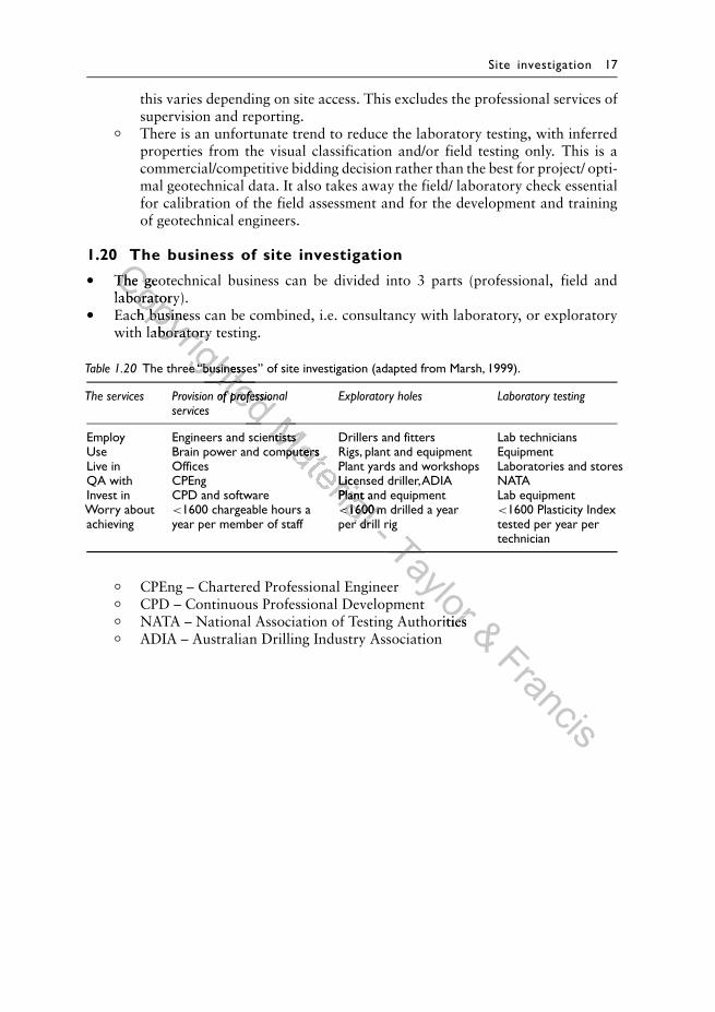
1.20 The business of site investigation
• The geotechnical business can be divided into 3 parts (professional, field andlaboratory).
• Each business can be combined, i.e. consultancy with laboratory, or exploratorywith laboratory testing.
Table 1.20 The three “businesses’’ of site investigation (adapted from Marsh, 1999).
The services Provision of professional Exploratory holes Laboratory testingservices
Employ Engineers and scientists Drillers and fitters Lab techniciansUse Brain power and computers Rigs, plant and equipment EquipmentLive in Offices Plant yards and workshops Laboratories and storesQA with CPEng Licensed driller,ADIA NATAInvest in CPD and software Plant and equipment Lab equipmentWorry aboutachieving
<1600 chargeable hours ayear per member of staff
<1600 m drilled a yearper drill rig
<1600 Plasticity Indextested per year pertechnician
◦ CPEng – Chartered Professional Engineer◦ CPD – Continuous Professional Development◦ NATA – National Association of Testing Authorities◦ ADIA – Australian Drilling Industry Association
Copyrighted
The geotechnical business can be divided into 3 parts (professional, field andCopyrighted
The geotechnical business can be divided into 3 parts (professional, field andlaboratory).
Copyrighted
laboratory).Each business can be combined, i.e. consultancy with laboratory, or exploratory
Copyrighted
Each business can be combined, i.e. consultancy with laboratory, or exploratorywith laboratory testing.
Copyrighted
with laboratory testing.
The three “businesses’’ of site investigation (adapted from Marsh, 1999).
Copyrighted The three “businesses’’ of site investigation (adapted from Marsh, 1999).
Copyrighted The services Provision of professional Exploratory holes
Copyrighted The services Provision of professional Exploratory holes
Copyrighted Material
Material
Employ Engineers and scientists Drillers and fitters Lab techniciansMaterial
Employ Engineers and scientists Drillers and fitters Lab techniciansUse Brain power and computers Rigs, plant and equipment Equipment
Material
Use Brain power and computers Rigs, plant and equipment EquipmentLive in Offices Plant yards and workshops Laboratories and stores
Material Live in Offices Plant yards and workshops Laboratories and storesQA with CPEng Licensed driller,ADIA NATA
Material QA with CPEng Licensed driller,ADIA NATAInvest in CPD and software Plant and equipment Lab equipment
Material Invest in CPD and software Plant and equipment Lab equipment
<
Material <1600 m drilled a year
Material 1600 m drilled a yearper drill rig
Material per drill rig- per drill rig- per drill rigTaylor
Taylor CPD – Continuous Professional Development
Taylor CPD – Continuous Professional Development
Taylor NATA – National Association of Testing Authorities
Taylor NATA – National Association of Testing Authorities& Francis