Embed Size (px)
Citation preview

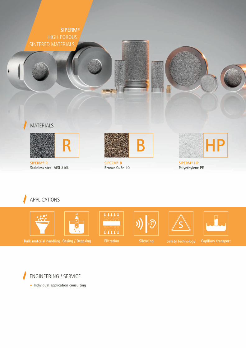
SIPERM®
HIGH POROUS
SINTERED MATERIALS
Customized SIPERM® solutions for industrial + technical applications
Tridelta SipermA TRIDELTA-Group Company

Since 1953 we produce highly porous sintered materials at our site in Dortmund.
Our many years of varied experience in the processing of PE (SIPERM® HP), Stain-
less steel (SIPERM® R) and Bronze (SIPERM® B) to high porous plates, pipes, mol-
ded parts and customized welding constructions makes us a competent partner in
the search for the best solution for your specific application problem.
Tridelta Siperm GmbH, formerly belonging to the Thyssen AG, is now a subsidiary
of Tridelta GmbH.
SIPERM® ALLROUNDERS
FOR HIGHEST DEMANDS
APPLICATIONS
ENGINEERING / SERVICE
Individual application consulting
SilencingBulk material handling Gasing / Degasing Filtration Safety technology Capillary transport
SIPERM® R
Stainless steel AISI 316LSIPERM® B
Bronze CuSn 10 SIPERM® HP
Polyethylene PE
MATERIALS
SIPERM®
HIGH POROUS
SINTERED MATERIALS

Material SIPERM® R
Product overview
Plates Size: 280 x 220 mm and 250 x 250 mm, seamless
Thickness: 2 - 10 mm
other sizes (weldments and cuts) upon request
Tubes seamless and as weldment – dimensions upon request
max. diameter for seamless tubes: 100 mm
max. length for seamless tubes: 1000 mm
Discs and
shaped parts
For the production of discs and shaped parts of di"erent sizes, we have a comprehensive tool park at our
disposal. Upon request, we will be pleased to inform you on available sizes and special shapes.
Fluidization units Aeration spot: Ø80 mm, Ø100 mm, Ø105 mm
Aeration pads: 250 x 125 mm, 500 x 125 mm, 1000 x 125 mm and according to customer specification
Fluidization bottoms according to customer specification
Filter cartridges seamless and as weldment – dimensions upon request
max. diameter for seamless tubes: 100 mm
max. length for seamless tubes: 1000 mm
Info
rmat
ion s
hee
t SI
PER
M® R
/ e
n /
© T
ride
lta
Sipe
rm G
mbH
/ 2
019
www.siperm.com
Stainless steel AISI 316L / 1.4404
Temperature resistance: 500 °C oxidizing atmosphere / 650 °C reducing atmosphere

Permeability according to DIN ISO 4022
Material SIPERM® R
measured on discs (Ø80 x 3 mm) / surface area perfused: 20 cm2 / correspond to 1 mm material thickness
www.siperm.com
Air at 20 °C Water at 20 °C
Bursting strength of tubes

Mat
eria
l SIP
ERM
® R
Tech
nic
al d
ata
Sta
inle
ss s
teel
AIS
I 316L
/
1.4
404
Tem
per
ature
res
ista
nce
: 500 °
C o
xidiz
ing a
tmosp
her
e /
650 °
C r
educi
ng a
tmosp
her
e
All
stat
ed v
alues
are
mea
n v
alues
; th
e si
ngl
e va
lues
can
di"
er a
ccor
ding
t o t
he
dim
ensi
ons
of t
he
com
ponen
ts.
Filt
er
gra
de
Den
sity
Poro
sity
Spec
ific
flow
coe$
cien
t
Sep
arat
ion
e$ci
ency
(liq
uid
) 98 %
Poro
met
er
ø p
ore
siz
e
Bubb
le P
oin
t
Pre
ssure
di&
eren
ce
Shea
r st
rength
Tensi
le
stre
ngth
Ben
din
g s
tren
gth
[g/c
m3]
[%]
lam
inar
[m2]
x10
-12
turb
ule
nt
[m]
x10
-7[µ
m]
[µm
][P
a][N
/mm
2]
[N/m
m2]
el
[N/m
m2]
0,1
[N
/mm
2]
Bre
akag
e[N
/mm
2]
R 1
5,9
- 6
,321
- 2
60,2
0,1
41,1
6225
390
120
50
75
340
R 3
5,2
- 5
,630 -
35
11
52,8
4245
320
110
50
7031
0
R 7
5,0
- 5
,432 -
37
26
94
3325
280
110
50
70280
R 1
04,9
- 5
,333 -
38
38
14
62535
240
100
50
70230
R 1
44,7
- 5
,136 -
41
515
18
81865
210
90
40
60
200
R 2
04,6
- 5
,037 -
42
830
30
13
1475
180
80
30
40
190
R 3
54,5
- 4
,938 -
43
15
45
37
20
1015
170
7030
40
180
R 6
04,4
- 4
,839 -
44
25
55
49
25
835
160
60
20
30
170
R 8
04,3
- 4
,740 -
45
28
68
55
32
705
140
50
20
30
140
R 1
00
4,1
- 4
,543 -
48
33
140
62
34
645
120
40
20
25
110
R 1
25
4,0
- 4
,444 -
49
35
145
65
37
555
110
40
15
20
100
R 1
50
3,8
- 4
,246 -
52
55
184
95
4141
590
35
1015
95
R 2
00
3,6
- 4
,049 -
54
112
300
110
65
215
80
30
1010
90
EN IS
O 2
73
8D
IN IS
O
30
911
-3
DIN
ISO
40
22
acc
ord
ing
to
ISO
45
72
AS
TM E
12
94
DIN
ISO
40
03
DIN
ISO
30
911
-6a
cco
rdin
g t
o
EN
ISO
27
40
acc
ord
ing
to
DIN
ISO
33
25

Please do not hesitate to contact us!
T +49 231 4501-221 · [email protected]
Turning Tool shape: Pointed finishing or side tool
Hard metal grades: ISO / ANSI K 20
E"ective cutting angle: 12°
Clearance angle: 7 - 9°
Depth of cut: 0.4 mm
Cutting speed: 10 – 30 m/min
Welding Porous sintered materials are welded by TIG. The material must be free from dirt and grease.
The welding speed must be as high as possible to achieve optimal reduction of heat influx
into the material.
Filler material: Thermanit JE-308 L Si or GE-316 L Si
Inert gas flow: 5 l/min
Electrode diameter: 1.4 – 4 mm
Current strength: 100 – 150 A (L = 3 mm)
Machining SIPERM® R can be rolled, bent, pressed, stamped, milled, turned or drilled, either cold after gentle
heating. SIPERM® R materials with a finer pore structure are generally more suitable for machining
than those of a coarser grade.
Any machining should avoid following the direction of perfusion flow, as the pores could become
blocked – water jet cutting and electrical discharge machining is, however, possible. When scrolling
or bending SIPERM® R plates, it should be noted that the minimum bending radius is dependent on
pore size and the material´s strength. Generally, however, the radius should not be less than 10 times
the wall thickness.
SIPERM® R semi-finished products can be joined by welding, riveting or bonding, both to other
SIPERM® components or di"erent materials, to form units or components of any size.
Machining instructions
Material SIPERM® R
Material SIPERM® R
Cleaning instructions
When all impurities are retained on the surface of the filter element without the penetration of particles
into the pore channels, mechanical cleaning is usually su&cient. The counterflow cleaning is not su&-
cient when impurities have solidified inside the filter. Then we recommend the chemical dissolution of
the residue in solvents which do not attack the filter.
Mechanical cleaning
This can easily be done by reverse washing (back-flushing)
in a clean liquid or gas without disassembling the
SIPERM®-component. The medium used for the reverse-
washing process may either be the filtrate itself or the
medium which is flowing through the SIPERM®-component.
It is however recommended to work with a gas counter-
flow, if the filtrate is a gas, or with a liquid counterflow,
if it is a liquid filtrate. If very dirty, the cleaning process is
more thorough, the more often it is repeated.
Also possible is the back-blowing with a hot steam, for
instance for vapor degreasing with a steam cleaner.
The cleaning e"ect in counterflow can be supported by
gently brushing with a soft brush (nylon brush). It is recom-
mended to carry out this process simultaneously with the
passage of the counterflow-medium in order to prevent
further accumulation.
For smaller, removable filter parts, the ultrasonic cleaning
by the resonance method is possible.
Chemical cleaning
The choice of the suitable solvent as well as the success of
the cleaning process depends on the nature of the impurity.
Therefore, recommendations can only be very general.
For the cleaning of SIPERM® R the following media
can be used:
All standard solvents such as benzene,
carbon tetrachloride, alcohol, acetone
Acetic acid up to 25 % (30 - 60 min)
Hydrochloric acid up to 10 % (max. 30 min)
Nitric acid 20 % (30 - 120 min)
Alkali- and alkaline earth metal solutions
It is not advisable, to use highly concentrated acids or
alkalis at higher temperatures. Neutralization with hot
water should be done in every case.
The length of cleaning and the temperature used can be
varied according to the degree of contamination. How-
ever, as a word of caution, it should not be forgotten that
compared to solid material, highly porous sintered material
has a vastly increased surface area and thus is far more
susceptible to any aggressive cleaning medium. For this
reason, the cleaning time and cleaning temperature must
not exceed the absolutely necessary level.
Depending on the application it must be ensured that the
highly porous sintered parts are dried thoroughly after
cleaning. Cleaning with solvents in any case requires a
complete drying of the porous sintered component before
reuse. Solvents should under no circumstances be used for
the cleaning of sintered components, which operate in
systems where, for safety reasons, the use or insertion of
solvents is prohibited.
In the case of metallic materials calcination is also pos-
sible, i.e. burning of crop residues at higher temperatures.

www.siperm.com
Tridelta Siperm GmbH Ostkirchstrasse 177 · 44287 Dortmund · Germany
T +49 231 4501-221 · F +49 231 4501-313 · [email protected]

www.siperm.com
Material SIPERM® B
Product overview
Plates Size: 250 x 500, 500 x 500, 750 x 450, 800 x 300, 1000 x 300, 1000 x 450 mm, seamless
Thickness: 2 - 10 mm
other sizes (weldments and cuts) upon request
Tubes seamless and as weldment – dimensions upon request
Discs and
shaped parts
For the production of discs and shaped parts of di"erent sizes, we have a comprehensive tool park at our
disposal. Upon request, we will be pleased to inform you on available sizes and special shapes.
Fluidization units Fluidization bottoms according to customer specification
Filter cartridges seamless and as weldment – dimensions upon request
Bronze CuSn 10
Temperature resistance: 200 °C oxidizing atmosphere / 350 °C reducing atmosphere
Info
rmat
ion s
hee
t SI
PER
M® B
/ e
n /
© T
ride
lta
Sipe
rm G
mbH
/ 2
019

Material SIPERM® B
www.siperm.com
Air at 20 °C Water at 20 °C
Bursting strength of tubes
Permeability according to DIN ISO 4022
measured on discs (Ø80 x 3 mm) / surface area perfused: 20 cm2 / correspond to 1 mm material thickness

Mat
eria
l SIP
ERM
® B
Tech
nic
al d
ata
Bro
nze
CuSn 1
0
Tem
per
ature
res
ista
nce
: 200 °
C o
xidiz
ing a
tmosp
her
e /
350 °
C r
educi
ng a
tmosp
her
e
All
stat
ed v
alues
are
mea
n v
alues
; th
e si
ngl
e va
lues
can
di"
er a
ccor
ding
t o t
he
dim
ensi
ons
of t
he
com
ponen
ts.
Filt
er
gra
de
Den
sity
Poro
sity
Spec
ific
flow
coe$
cien
t
Sep
arat
ion
e$ci
ency
(li-
quid
) 98 %
Poro
met
er
ø p
ore
siz
e
Bubb
le P
oin
t
Pre
ssure
di&
eren
ce
Shea
r st
rength
Tensi
le
stre
ngth
Ben
din
g s
tren
gth
[g/c
m3]
[%]
lam
inar
[m2]
x10
-12
turb
ule
nt
[m]
x10
-7[µ
m]
[µm
][P
a][N
/mm
2]
[N/m
m2]
el
[N/m
m2]
0,1
[N
/mm
2]
Bre
akag
e[N
/mm
2]
B 5
6,0
- 6
,427 -
32
11,5
12
35225
200
120
60
80
200
B 8
5,7
- 6
,131
- 3
54
16
19
62425
170
105
60
70150
B 1
25,1
- 5
,933 -
38
635
28
91725
150
100
40
40
130
B 2
05,4
- 5
,834 -
39
16
54
42
18
1125
140
65
25
30
90
B 4
05,2
- 5
,636 -
41
65
120
75
34
625
110
30
15
25
40
B 8
05,0
- 5
,439 -
43
80
200
131
55
525
90
25
15
20
35
B 1
20
4,9
- 5
,340 -
44
90
250
225
70325
80
20
1010
25
B 1
50
4,7
- 5
,142 -
47
120
300
251
90
225
60
1010
1025
B 2
00
4,5
- 4
,944 -
49
180
400
301
105
125
40
55
510
EN IS
O 2
73
8D
IN IS
O
30
911
-3
DIN
ISO
40
22
acc
ord
ing
to
ISO
45
72
AS
TM E
12
94
DIN
ISO
40
03
DIN
ISO
30
911
-6a
cco
rdin
g t
o
EN
ISO
27
40
acc
ord
ing
to
DIN
ISO
33
25

Turning Tool shape: Pointed finishing or side tool
Hard metal grades: ISO / ANSI K 20
E"ective cutting angle: 10°
Clearance angle: 10°
Depth of cut: 0.5 mm
Cutting speed: 100 – 300 m/min
Welding Porous sintered materials are welded by TIG. The material must be free from dirt and grease.
The welding speed must be as high as possible to achieve optimal reduction of heat influx
into the material.
Filler material: Bronze wire CuSn 9 or CuSn 10
Inert gas flow: 5 l/min
Electrode diameter: 1.5 – 3 mm
Current strength: 70 – 120 A
Machining SIPERM® B can be rolled, bent, pressed, stamped, milled, turned or drilled, either cold after gentle
heating. SIPERM® B materials with a finer pore structure are generally more suitable for machining
than those of a coarser grade.
Any machining should avoid following the direction of perfusion flow, as the pores could become
blocked – water jet cutting and electrical discharge machining is, however, possible. When scrolling
or bending SIPERM® B plates, it should be noted that the minimum bending radius is dependent on
pore size and the material´s strength. Generally, however, the radius should not be less than 10 times
the wall thickness.
SIPERM® B semi-finished products can be joined by welding, riveting or bonding, both to other
SIPERM® components or di"erent materials, to form units or components of any size.
Material SIPERM® B
Machining instructions
Please do not hesitate to contact us!
T +49 231 4501-221 · [email protected]

Material SIPERM® B
When all impurities are retained on the surface of the filter element without the penetration of par-
ticles into the pore channels, mechanical cleaning is usually su&cient. The counterflow cleaning is not
su&cient when impurities have solidified inside the filter. Then we recommend the chemical dissolution
of the residue in solvents which do not attack the filter.
Mechanical cleaning
This can easily be done by reverse washing (back-flushing)
in a clean liquid or gas without disassembling the
SIPERM®-component. The medium used for the reverse-
washing process may either be the filtrate itself or the
medium which is flowing through the SIPERM®-component.
It is however recommended to work with a gas counter-
flow, if the filtrate is a gas, or with a liquid counterflow,
if it is a liquid filtrate. If very dirty, the cleaning process is
more thorough, the more often it is repeated.
Also possible is the back-blowing with a hot steam, for
instance for vapor degreasing with a steam cleaner.
The cleaning e"ect in counterflow can be supported by
gently brushing with a soft brush (nylon brush). It is recom-
mended to carry out this process simultaneously with the
passage of the counterflow-medium in order to prevent
further accumulation.
For smaller, removable filter parts, the ultrasonic cleaning
by the resonance method is possible.
Chemical cleaning
The choice of the suitable solvent as well as the success of
the cleaning process depends on the nature of the impurity.
Therefore, recommendations can only be very general.
For the cleaning of SIPERM® B the following media
can be used:
All standard solvents such as benzene,
carbon tetrachloride, alcohol, acetone
Acetic acid up to 25 % (30 - 60 min) or 20 % (1 - 2 h)
Hydrochloric acid up to 10 % (30 - 60 min)
Alkali- and alkaline earth metal solutions
After dissolving and flushing out the impurities, the neu-
tralization with hot water is advisable, and if necessary,
a potassium-dichromatepickling, followed by thorough
rinsing.
The length of cleaning and the temperature used can be
varied according to the degree of contamination. How-
ever, as a word of caution, it should not be forgotten that
compared to solid material, highly porous sintered material
has a vastly increased surface area and thus is far more
susceptible to any aggressive cleaning medium. For this
reason, the cleaning time and cleaning temperature must
not exceed the absolutely necessary level.
Depending on the application it must be ensured that the
highly porous sintered parts are dried thoroughly after
cleaning. Cleaning with solvents in any case requires a
complete drying of the porous sintered component before
reuse. Solvents should under no circumstances be used for
the cleaning of sintered components, which operate in
systems where, for safety reasons, the use or insertion of
solvents is prohibited.
In the case of metallic materials calcination is also pos-
sible, i.e. burning of crop residues at higher temperatures.
Cleaning instructions

www.siperm.com
Tridelta Siperm GmbH Ostkirchstrasse 177 · 44287 Dortmund · Germany
T +49 231 4501-221 · F +49 231 4501-313 · [email protected]

Product overview
Material SIPERM® HP
Plates Size: 1000 x 1000 mm and 1200 x 1000 mm; Thickness: 3 - 20 mm
other sizes (weldments and cuts) upon request
Cam plates Size: 850 x 850 mm; Thickness: 5 - 8 mm
Sintered spacer cams make an additional support redundant.
Tubes seamless and as weldment – dimensions upon request
Discs and
shaped parts
For the production of discs and shaped parts of di"erent sizes, we have a comprehensive tool park at our
disposal. Upon request, we will be pleased to inform you on available sizes and special shapes.
Fluidization units seamless fluidization bottoms – dimensions upon request
welded fluidization bottoms according to customer specification
Filter cartridges seamless and as weldment – dimensions upon request
www.siperm.com
Polyethylene / PE-UHMW / HDPE
Temperature resistance: approx. 70 °C oxidizing atmosphere
Info
rmat
ion s
hee
t SI
PER
M® H
P /
en /
© T
ride
lta
Sipe
rm G
mbH
/ 2
019

Material SIPERM® HP
measured on discs (Ø80 x 5,7 mm) / surface area perfused: 20 cm2 / correspond to 1 mm material thickness
www.siperm.com
Air at 20 °C Water at 20 °C
Permeability according to DIN ISO 4022

Mat
eria
l SIP
ERM
® H
P
Poly
ethyl
ene
/
PE-U
HM
W
/ H
DPE
T em
per
ature
res
ista
nce
: ap
pro
x. 7
0 °
C o
xidiz
ing a
tmosp
her
e
All
stat
ed v
alues
are
mea
n v
alues
; th
e si
ngl
e va
lues
can
di"
er a
ccor
ding
to t
he
dim
ensi
ons
of t
he
com
ponen
ts.
Tech
nic
al d
ata
Filt
er g
rade
Den
sity
Poro
sity
Spec
ific
flow
coe$
cien
t
Poro
met
er
ø p
ore
siz
e
Bubb
le P
oin
t
Pre
ssure
di%
eren
ce
Shea
r st
rength
Tensi
le s
tren
gth
Elo
ngat
ion
[g/c
m3]
[%]
lam
inar
[m2]
x10
-12
turb
ule
nt
[m]
x10
-7[µ
m]
[Pa]
[N/m
m2]
[N/m
m2]
[%]
HP
FI0,5
8 -
0,6
235 -
39
12
100
22
825
12
835
HP
50,5
6 -
0,6
235 -
39
0,7
6,5
73551
104
50
HP
100,5
6 -
0,6
037 -
41
3,4
20
12
1825
84
30
HP
20
0,5
3 -
0,5
740 -
44
1151
18
1075
95
40
HP
40
0,5
1 -
0,5
542 -
46
19
60
35
425
64
20
HP
60
0,5
4 -
0,6
136 -
43
23
72
62
210
75
16
HP
80
0,4
6 -
0,5
443 -
52
30
80
78
125
75
15
HP
100
0,4
1 -
0,4
752 -
57
48
101
97
105
65
12
HP
anti
stat
ic0,4
9 -
0,5
344 -
48
15
55
22
775
43
15
HP
FI-R
0,5
8 -
0,6
235 -
39
12
100
22
825
12
735
EN IS
O 2
73
8D
IN IS
O 3
091
1-3
DIN
ISO
40
22
AS
TM E
12
94
DIN
ISO
40
03
DIN
ISO
30
911
-6a
cco
rdin
g t
o
EN
ISO
27
40
acc
ord
ing
to
DIN
ISO
33
25
HP F
I – S
tanda
rd p
late
mat
eria
l fo
r fl
uid
izat
ion
HP a
nti
stat
ic –
Sta
nda
rd m
ater
ial an
tist
atic
; Su
rfac
e re
sist
ivit
y <
106
Ohm
/ A
ll ot
her
HP
grad
es a
re a
lso
avai
labl
e in
ant
ista
tic
vers
ion.
HP F
l-R
– S
tain
less
ste
el in
filt
rate
d st
anda
rd p
late
mat
eria
l for
flui
diza
tion
. The
mat
eria
l is
dete
ctab
le a
nd t
here
fore
sui
tabl
e fo
r us
e in
the
foo
d in
dust
ry.

Turning Tool shape: Pointed finishing or side tool
E"ective cutting angle: 5 - 30°
Clearance angle: 10 - 15°
Depth of cut: 0.1 - 0.5 mm
Cutting speed: 200 – 500 m/min
Welding Hot gas and heated tool welding
Filler material: Polyethylene wire (Natural PE)
Electrode diameter: 3 – 5 mm
Welding temperature: 200 – 250 °C
Machining SIPERM® HP can be rolled, bent, pressed, stamped, milled, turned or drilled, either cold after gentle
heating. SIPERM® HP materials with a finer pore structure are generally more suitable for machining
than those of a coarser grade.
Any machining should avoid following the direction of perfusion flow, as the pores could become
blocked – water jet cutting and electrical discharge machining is, however, possible. When scrolling
or bending SIPERM® HP plates, it should be noted that the minimum bending radius is dependent on
pore size and the material´s strength. Generally, however, the radius should not be less than 10 times
the wall thickness.
SIPERM® HP semi-finished products can be joined by welding, riveting or bonding, both to other
SIPERM® components or di"erent materials, to form units or components of any size.
Material SIPERM® HP
Machining instructions
Please do not hesitate to contact us!
T +49 231 4501-221 · [email protected]

Material SIPERM® HP
Cleaning instructions
When all impurities are retained on the surface of the filter element without the penetration of particles
into the pore channels, mechanical cleaning is usually su'cient. The counterflow cleaning is not su'-
cient when impurities have solidified inside the filter. Then we recommend the chemical dissolution of
the residue in solvents which do not attack the filter.
This can easily be done by reverse washing (back-flushing)
in a clean liquid or gas without disassembling the
SIPERM®-component. The medium used for the reverse-
washing process may either be the filtrate itself or the
medium which is flowing through the SIPERM®-component.
It is however recommended to work with a gas counter-
flow, if the filtrate is a gas, or with a liquid counterflow,
if it is a liquid filtrate. If very dirty, the cleaning process is
more thorough, the more often it is repeated.
Also possible is the back-blowing with a hot steam, for
instance for vapor degreasing with a steam cleaner.
The cleaning e"ect in counterflow can be supported by
gently brushing with a soft brush (nylon brush). It is recom-
mended to carry out this process simultaneously with the
passage of the counterflow-medium in order to prevent
further accumulation.
For smaller, removable filter parts, the ultrasonic cleaning
by the resonance method is possible.
Mechanical cleaning Chemical cleaning
The choice of the suitable solvent as well as the success of
the cleaning process depends on the nature of the impurity.
Therefore, recommendations can only be very general.
For the cleaning of SIPERM® HP the following media
can be used:
Solvents: acetone, ethanol, methanol, benzine (RT)
Acetic acid 10 %
Hydrofluoric acid 40 %
Hydrochloric acid (any concentration)
Nitric acid 25 %
Sodium hydroxide solution
The length of cleaning and the temperature used can be
varied according to the degree of contamination. How-
ever, as a word of caution, it should not be forgotten that
compared to solid material, highly porous sintered material
has a vastly increased surface area and thus is far more
susceptible to any aggressive cleaning medium. For this
reason, the cleaning time and cleaning temperature must
not exceed the absolutely necessary level.
Depending on the application it must be ensured that the
highly porous sintered parts are dried thoroughly after
cleaning. Cleaning with solvents in any case requires a
complete drying of the porous sintered component before
reuse. Solvents should under no circumstances be used for
the cleaning of sintered components, which operate in
systems where, for safety reasons, the use or insertion of
solvents is prohibited.
Please note that when cleaning SIPERM® HP with surfac-
tants, the material loses its hydrophobic property.
Moreover, surfactants reduce the material’s resistance to
cracking.

www.siperm.com
Tridelta Siperm GmbH Ostkirchstrasse 177 · 44287 Dortmund · Germany
T +49 231 4501-221 · F +49 231 4501-313 · [email protected]

Storage, mixing and discharge of bulk materials with average particle sizes of less than 0.2 mm frequently cau-
ses problems because these bulk materials do not flow freely and therefore are almost impossible to discharge.
They tend to agglomerate and form bridges and tunnels, particularly around the silo outlet, thereby obstructing
the free flow of the material from the storage vessel.
Such low flowable materials include fine plastic powders, flour, pigments, soot, cement, pesticides etc.
www.siperm.com
Fluidization of bulk materials with
SIPERM® aeration components
Info
rmat
ion
shee
t Fl
uidi
zati
on /
en
/ ©
Trid
elta
Sip
erm
Gm
bH /
201
8
The solution to the problems of discharging bulk materials
A proven solution for the problem-free handling of bulk solids with average grain sizes between 10 and 200 µm is the fluidization of the
material using pneumatic aeration units made from highly porous SIPERM® materials.
Custom-made aeration bottoms, cones or inserts which we manufacture to your specifications
Plate material for adapting to your own systems
Standard aeration pads which can easily be retrofitted into existing systems
You can choose between:

Fluidization inserts made of SIPERM®
The operating principle of the fluidization inserts made of
SIPERM® is shown in the graphic below.
Fluidization of bulk materials with SIPERM® aeration components
www.siperm.com
Dry, dust-free air is injected to reduce the friction and cohesive
forces of the bulk material, producing a continuous flow of the
material from the vessel. Air supply pressure and velocity of air
must be set at such a rate that the contents of the silo are evenly
loosened.
When fitting-out large silo areas with aeration units, it is ad-
vantageous to divide them into sectors each of which can be
interchangeably aerated. The sectors can be arranged in a radial
pattern or laid out concentrically starting from an inner ring. In
this way it is possible to aerate even large areas with relatively
low air quantities. In many cases it is su%cient to compensate
the pressures produced by the bulk material during storage by
the inflowing air.
The support of the fluidization insert is usually realized with sup-
porting ribs. Depending on the material and system conditions,
these are either welded to the side of the fluidization insert away
from the product, or attached to the inside of the solid outer
vessel.
Fluidization cones: The medium (e.g., air, nitrogen, etc.) used for
the operation must be dry and free from dirt and grease/oil. The
required gas quantities depend on the respective application
(ventilation, fluidization, homogenization or drying), the plant
dimensions and the bulk material properties. For applications
for discharge improvement in fully lined bins, the typical gas
amounts needed are 100-300 m3/(m2*h).
In the case of partial linings with fluidization pads or applica-
tions for drying or homogenization, the gas quantities may be
correspondingly higher. The pressure loss is dependent on the
porous material used and the material thickness, the size of the
surface to be ventilated, the amount of gas supplied and the
dimensions of certain components of the compressed air system
(pipe diameter, pipeline management, etc.).
Operating notes
Sealing ring
Flange
Porous Fluidization insert
Sealing ring
Outer vessel
Compressed air line
Installation fluidization insert
Fluidization of bulk materials with SIPERM® aeration components
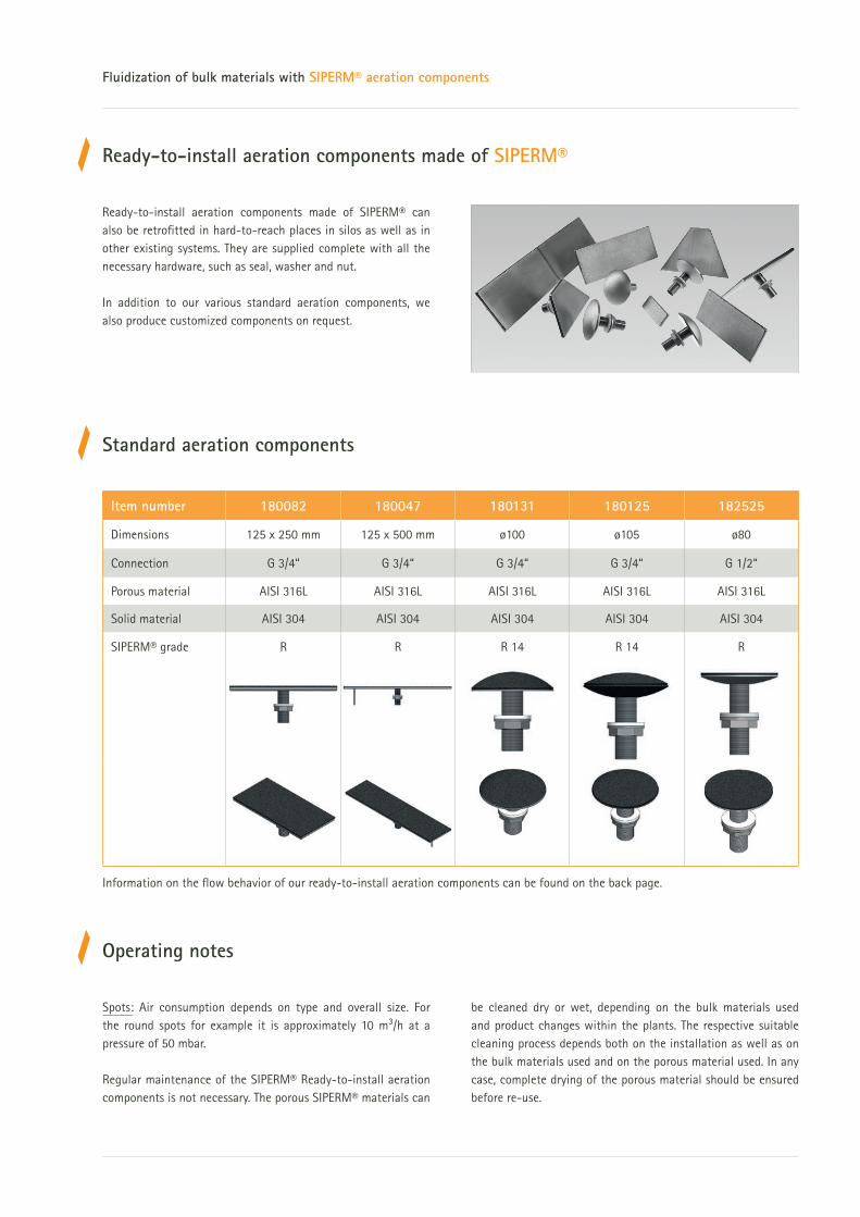
Ready-to-install aeration components made of SIPERM®
Ready-to-install aeration components made of SIPERM® can
also be retrofitted in hard-to-reach places in silos as well as in
other existing systems. They are supplied complete with all the
necessary hardware, such as seal, washer and nut.
In addition to our various standard aeration components, we
also produce customized components on request.
Standard aeration components
Spots: Air consumption depends on type and overall size. For
the round spots for example it is approximately 10 m3/h at a
pressure of 50 mbar.
Regular maintenance of the SIPERM® Ready-to-install aeration
components is not necessary. The porous SIPERM® materials can
be cleaned dry or wet, depending on the bulk materials used
and product changes within the plants. The respective suitable
cleaning process depends both on the installation as well as on
the bulk materials used and on the porous material used. In any
case, complete drying of the porous material should be ensured
before re-use.
Operating notes
Information on the flow behavior of our ready-to-install aeration components can be found on the back page.
Item number 180082 180047 180131 180125 182525
Dimensions 125 x 250 mm 125 x 500 mm ø100 ø105 ø80
Connection G 3/4“ G 3/4“ G 3/4“ G 3/4“ G 1/2“
Porous material AISI 316L AISI 316L AISI 316L AISI 316L AISI 316L
Solid material AISI 304 AISI 304 AISI 304 AISI 304 AISI 304
SIPERM® grade R R R 14 R 14 R

Please do not hesitate to contact us!
T +49 231 4501-221 · [email protected]
www.siperm.com
Tridelta Siperm GmbH Ostkirchstrasse 177 · 44287 Dortmund · Germany
T +49 231 4501-221 · F +49 231 4501-313 · [email protected]
Spot 180125
Spot 180131
Pad 180082
Pad 180047
Fluidization of bulk materials with SIPERM® aeration components
Permeability measured on R 14

Filtering roller
1 2
Pressure roller
Powder
Compacted granulate
Fine-grained bulk materials such as colouring pigments, manganese dioxide, soot, cement, coal dust, various
ceramic powders, powders for the food industry, pesticides and many other materials are very di"cult to handle.
They have a very large bulk volume, i.e. a very low bulk density, and produce large amounts of dust when trans-
ferred. In these cases compaction of powders is aimed at.
Such fine-grained bulk materials can be compacted down to 20 % of their bulk volume using vacuum compaction rollers or suction
pipes made from SIPERM® materials. A distinction is made between two processes:
The solution: Vacuum compaction rollers and suction pipes
www.siperm.com
Compaction by means of vacuum compaction rollers
Deaerating and compacting bulk
solids using SIPERM® materials
Coverings for compaction rollers made of SIPERM® R
The powder is compacted through a combination of mechanical pressure and vacuum. Normally, a filtering roller (1) and a pressure
roller (2) run against each other. The powder is dispersed between the two rollers and sucked up and pre-compacted by the vacuum
roller. The resulting filter cake is then compacted in the gap between the two rollers at a preset pressure. The compacted product is
removed from the roller with a stripper and drops into the collecting vessel.
Vacuum compaction rollers are covered with SIPERM® R. The highly porous material is characterized by high compressive strength,
temperature stability and chemical resistance, and is, therefore, suitable for a wide range of applications. The highly porous SIPERM®
material used for covering the compaction rollers is available in sheet form and can be welded to create larger units and adapted by
rolling to the radius of the roller body. This can either be done by the customer himself or by Tridelta Siperm GmbH.
Info
rmat
ion s
hee
t D
eaer
atin
g an
d co
mpa
ctin
g /
en /
© T
ride
lta
Sipe
rm G
mbH
/ 2
018

Volume reduction by means of suction pipes
Suction pipes made from SIPERM® are suitable for reducing the volume of bulk materials in bags or vessels. These pipes are dipped in
the bulk material to be compacted, either during or after the filling process. By sucking the excess air, the filling volume of the bulk
material in the container is significantly reduced.
Depending on application, di&erent materials and filtration grades are used. We supply seamless pipes made from stainless steel, bronze
or polyethylene.
Deaerating and compacting bulk solids using SIPERM® materials
Suction pipes made of SIPERM® R and SIPERM® B SIPERM® HP SIPERM® R
www.siperm.com
Tridelta Siperm GmbH Ostkirchstrasse 177 · 44287 Dortmund · Germany
T +49 231 4501-221 · F +49 231 4501-313 · [email protected]
Please do not hesitate to contact us!
T +49 231 4501-221 · [email protected]

Particulate residues in gases or liquids can lead to contamination in many applications. These pollutants hinder
the desired processes or do not comply with legal regulations on environmental protection. In other cases,
particles are to be recovered from a medium stream for economic reasons.
Stainless steel filters - SIPERM® R (Pore size 1 - 200 µm)
Filtration is a fundamental procedure in many manufacturing
processes. Porous sinter materials are ideally suited for filter
functions in various applications.
Depending on the application, filter materials made from Stain-
less steel (SIPERM® R), Bronze (SIPERM® B) or Polyethylene
(SIPERM® HP) are used. The SIPERM® materials consist of
powders, which are melded to porous bodies by sintering.
Depending on the powder particle size of the starting material,
di#erent porosities and filter fineness can be realized. The manu-
facturing process allows almost any geometry.
The selection of the appropriate SIPERM® material depends on
the application temperature, the materials to be filtered, as
well as the pressure loss and the deposition rate. Depending on
the application, it is possible to choose from a large number of
di#erent pore size distributions in order to achieve the best
possible filtration result.
Stainless steel filters - SIPERM® R (AISI 316 L / 1.4404)
Pore size 1 - 200 µm
High chemical resistance
Even at high temperatures mechanically extremely
resilient and dimensionally stable
Food-safe
Suitable for back-flushing and other cleaning processes
Application examples:
Filtration of viscous plastic melts
Filter cartridges for gas filtration in chemical processes
Dust removal in measuring devices and electrical systems
Applications for filter materials made from SIPERM®
Info
rmat
ion s
hee
t Fi
ltra
tion
/ e
n /
© T
ride
lta
Sipe
rm G
mbH
/ 0
3-2
018
www.siperm.com
Filtration with SIPERM®

www.siperm.com
Please do not hesitate to contact us!
T +49 231 4501-221 · [email protected]
Filtration with SIPERM®
Plastic filters - SIPERM® HP (PE)
Pore size 5 - 200 µm
Very high chemical resistance
Mechanically very stable, in particular also
with changing load
Realizable in complex geometry and high quantity
Food-safe, with FDA-certificate
Hydrophobic; hydrophilic adjustable
Application examples:
Dust removal, e.g. in automotive industry or valve technology
Filter heads for humidity sensors
Base material for dimensionally stable activated carbon filters
Plastic filters - SIPERM® HP (Pore size 5 - 200 µm)
Bronze filters - SIPERM® B (CuSn 10)
Pore size 5 - 200 µm
Low pressure losses
Very homogeneous pore structure due
to almost fully spherical base material
Application examples:
Oil filters for hydraulic brake systems
Gas filters in compressed air equipment Bronze filters - SIPERM® B (Pore size 5 - 200 µm)
Please do not hesitate to contact us!
T +49 231 4501-221 · [email protected]
In the above-mentioned cases and in case of continuous air re-
lease as in air motors and explosively released air as in pistons,
silencers made of SIPERM® provide an e#ective way to reduce
the noise significantly.
Due to their long, tortuous pore channels, SIPERM® materials
achieve excellent sound reduction. In the pores, the air flow is
strongly swirled, the direction of flow is split and the air flow is
slowed down. While the flow speed is slowing down, the sound
energy is converted to frictional heat and part of the sound wave
energy is absorbed by the porous body (absorption attenuation).
With conventional SIPERM® silencers, the total sound insulation
e#ect is up to 20 dB (A).
The solution: Reduction of the sound emission
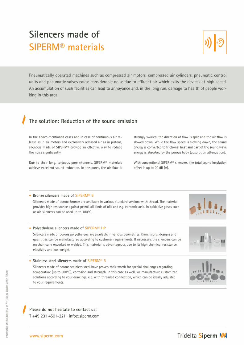
Silencers made of
SIPERM® materials
Info
rmat
ion s
hee
t Si
lence
rs /
en /
© T
ride
lta
Sipe
rm G
mbH
/ 2
018
www.siperm.com
Bronze silencers made of SIPERM® B
Silencers made of porous bronze are available in various standard versions with thread. The material
provides high resistance against petrol, all kinds of oils and e.g. carbonic acid. In oxidative gases such
as air, silencers can be used up to 180°C.
Polyethylene silencers made of SIPERM® HP
Silencers made of porous polyethylene are available in various geometries. Dimensions, designs and
quantities can be manufactured according to customer requirements. If necessary, the silencers can be
mechanically reworked or welded. This material is advantageous due to its high chemical resistance,
elasticity and low weight.
Stainless steel silencers made of SIPERM® R
Silencers made of porous stainless steel have proven their worth for special challenges regarding
temperature (up to 500°C), corrosion and strength. In this case as well, we manufacture customized
solutions according to your drawings, e.g. with threaded connection, which can be ideally adjusted
to your requirements.
Pneumatically operated machines such as compressed air motors, compressed air cylinders, pneumatic control
units and pneumatic valves cause considerable noise due to e&uent air which exits the devices at high speed.
An accumulation of such facilities can lead to annoyance and, in the long run, damage to health of people wor-
king in this area.
Please do not hesitate to contact us!
T +49 231 4501-221 · [email protected]
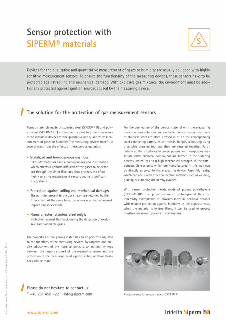
Devices for the qualitative and quantitative measurement of gases or humidity are usually equipped with highly
sensitive measurement sensors. To ensure the functionality of the measuring devices, these sensors have to be
protected against soiling and mechanical damage. With explosive gas mixtures, the environment must be addi-
tionally protected against ignition sources caused by the measuring device.
Porous materials made of stainless steel (SIPERM® R) and poly-
ethylene (SIPERM® HP) are frequently used to protect measure-
ment sensors in devices for the qualitative and quantitative mea-
surement of gases or humidity. The measuring devices benefit in
several ways from the e#ects of these porous materials.
Stabilized and homogeneous gas flow:
SIPERM® materials have a homogeneous pore distribution
which e#ects a uniform di#usion of the gases to be detec-
ted through the sinter filter and thus protects the often
highly sensitive measurement sensors against significant
fluctuations.
Protection against soiling and mechanical damage:
The particles present in the gas stream are retained by the
filter e#ect. At the same time, the sensor is protected against
impact and shock loads.
Flame arrester (stainless steel only):
Protection against flashback during the detection of explo-
sive and flammable gases.
The properties of our porous materials can be perfectly adjusted
to the functions of the measuring devices. By targeted and pre-
cise adjustment of the material porosity, an optimal synergy
between the response speed of the measuring sensor and the
protection of the measuring head against soiling or flame flash-
back can be found.
The solution for the protection of gas measurement sensors
Sensor protection with
SIPERM® materials
Info
rmat
ion s
hee
t S
enso
r pr
otec
tion
/ e
n /
© T
ride
lta
Sipe
rm G
mbH
/ 2
018
www.siperm.com
For the connection of the porous material with the measuring
device various solutions are available. Porous geometries made
of stainless steel are often pressed in or on the corresponding
solid connecting parts such as threads, flanges or housing using
a suitable pressing tool and then are sintered together. Parti-
cularly at the interfaces between porous and non-porous ma-
terials stable chemical compounds are formed in the sintering
process, which lead to a high mechanical strength of the com-
ponents. Sensor units which are manufactured in this way can
be directly screwed to the measuring device. Assembly faults,
which can occur with other connection methods such as welding,
glueing or clamping are hereby avoided.
With sensor protection heads made of porous polyethylene
(SIPERM® HP) other properties are in the foreground. Thus, the
inherently hydrophobic PE provides moisture-sensitive sensors
with reliable protection against humidity. In the opposite case,
when the material is hydrophilized, it can be used to protect
moisture measuring sensors in soil analysis.
Protective caps for sensors made of SIPERM® R

Specific permeability
Volu
me
flow
Turbulent
flow
Laminar
flow
Pressure di"erence
To estimate the pressure drop for a given volume flow, Darcy’s equation
is to be used which illustrates the relationship in a simplified manner:
Permeability / Volume flow / Pressure drop
Calculation basis for
SIPERM® materials
Info
rmat
ion
shee
t C
alcu
lati
on b
asis
/ e
n /
© Tr
idel
ta S
iper
m G
mbH
/ 2
018
www.siperm.com
= V ·
A ·
.
= pressure drop in the filter [N⁄m2]
V = volume flow (average volume of the flowing medium) [m3/s]
s = thickness of the filter [m]
A = flow-through cross section of the filter [m2]
= average dynamic viscosity of the flowing medium [Ns/m2]
= specific laminar permeability coe&cient [m2]
This formula applies to low flow velocities if there is only a laminar flow.
At higher pressure di"erences and higher flow velocities, the relation
between pressure drop and volume flow is no longer linear but can be
divided into a laminar and a turbulent proportion. This, however, only
applies to very high Reynolds numbers.
= V · s
A· +
A·
V.
= specific turbulent permeability coe&cient [m]
= average density of the flowing medium [kg/m3]
Please do not hesitate to contact us!
T +49 231 4501-221 · [email protected]
The volume flow of a medium through a filter depends on the existing pressure di"erence and increases up to a
maximum value which is reached asymptotically. The permeability measurement is usually performed in accor-
dance with DIN ISO 4022 using gases. The measured values include the pressure di"erence ∆p upstream and
downstream of the filter and the flow rate at constant pressure and temperature. Filter surface and filter thick-
ness are also constant in this test set-up so that the filter material coe&cients can be determined based on the
test curves.
.
.

Quality standards of SIPERM® products
Only by applying comprehensive and reliable quality assurance measures at all levels ensures the
product and service quality demanded by customers. Our e�orts in pursuing this object have secured us
DIN EN ISO 9001:2015 certification.
Quality assurance
Bubble-Point-Test (according to DIN ISO 4003) for determination of maximum pore size
Permeability Test (according to DIN ISO 4022) for determination of specific permeability
Electronically controlled testing of admission pressure, di�erential pressure, flow rate
Porometer measurements (according to ASTM F 316-03) for determination of pore size distribution
Determination of filter separating capacity ratings – support by independent institutes assays
Determination of the tensile and shearing strength (according to DIN 30910, Part 2)
Customized measurements
Energy management
We are certified according to ISO 50001.
To guarantee constant high quality properties, our products are subjected to the following series of tests:
Tridelta Siperm GmbH
Ostkirchstrasse 177
44287 Dortmund · Germany
T +49 231 4501-221
www.siperm.com