Embed Size (px)
Citation preview
SIP SIGNALLING DELAY IN 3GPP
Alexander A. Kist and Richard J. Harris RMIT University, BOX 2476V, Victoria 3001, Australia {kist,richard}<i!catt.rmit.edu.au
Abstract The Session Initiation Protocol (SIP) will be used as the signalling protocol in the IP Multimedia Subsystem (IMS) of 3rd Generation Partnership Project (3GPP) UMTS networks. This paper discusses the delay as a relevant signalling Quality of Service (QoS) parameter. It outlines possible problems concerning the delay for signalling messages and provides empirical estimates for expected delays using existing UDP delay trace data. Simulation results verify the estimates. lt is concluded that further study is required to ensure satisfactory QoS, in particular if 3GPP IM Subsystem is to provide equivalent telephony services.
1. Introduction SignaHing traffic is· considered to be an important type of network
traffic and lost signaHing messages or congestion of the signaHing network can have a devastating impact on all services that rely on signaHing sessions. Providing QoS for signalling is therefore one of the critical tasks in implementing session related services.
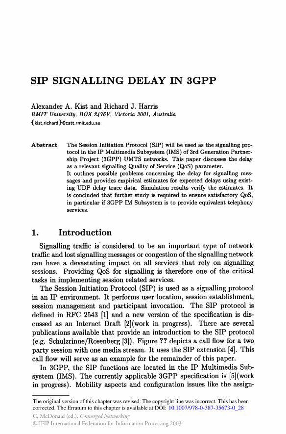
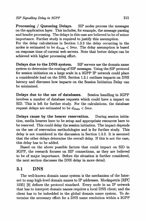
The Session Initiation Protocol (SIP) is used as a signaHing protocol in an IP environment. It performs user location, session establishment, session management and participant invocation. The SIP protocol is defined in RFC 2543 [1] and a new version of the specification is discussed as an Internet Draft [2](work in progress). There are several publications available that provide an introduction to the SIP protocol (e.g. Schulzrinne/Rosenberg [3]). Figure ?? depicts a call flow for a two party session with one media stream. It uses the SIP extension [4]. This call flow will serve as an example for the remainder of this paper.
In 3GPP, the SIP functions are located in the IP Multimedia Subsystem (IMS). The currently applicable 3GPP specification is [5](work in progress). Mobility aspects and configuration issues like the assign-
The original version of this chapter was revised: The copyright line was incorrect. This has beencorrected. The Erratum to this chapter is available at DOI:
© IFIP International Federation for Information Processing 2003C. McDonald (ed.), Converged Networking
10.1007/978-0-387-35673-0_28
212
UE1 Proxles I
I INVIT== t I I -'oo INVITE
I. 183w/SDP-183w/SDP- I
PRACK Rnltvallon PRACK-
ReiiiValion I. 200 OK (ol PRACK)__.__
200 OK (ol PRACK)- I
UPDATE-t I
-UPDATE
I t 1 111ar Alorlld 1
f.---20001< (oiUPOATE) 1: _,ao I :::ao I I I
PRACK I PRACK
I 1: t I uaar Plclca-Up I 1.----200 OK (ol PRACK)- I 200011 I I+ =-200011 I I ACK
I ACK --l I
Figv.re 1. Session Message Flow
ment of the IP address to User Equipment (UE) are not the focus of this paper.
3GPP uses several different SIP proxy servers. They are abbreviated by CSCF, the Call Session Control Function [5). These different signalling nodes provide various functions like database requests, recording state information for billing, and serve application layer firewalls nodes. These details are not of specific interest in this paper and the nodes are seen as general SIP proxy servers.
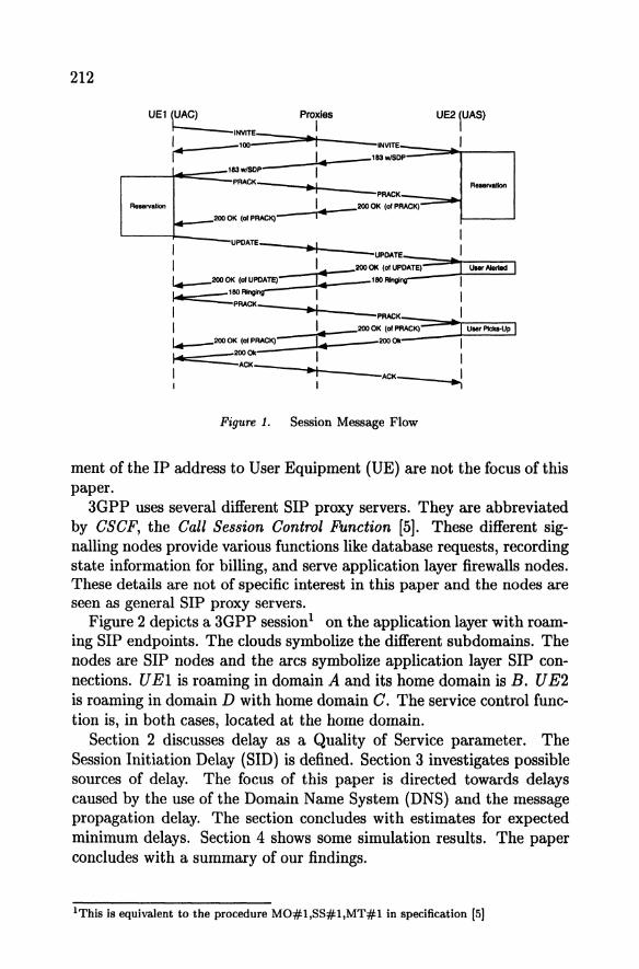
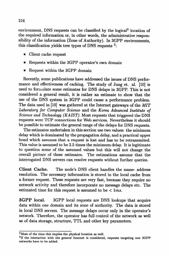
Figure 2 depicts a 3GPP session1 on the application layer with roaming SIP endpoints. The clouds symbolize the different subdomains. The nodes are SIP nodes and the arcs symbolize application layer SIP connections. U El is roaming in domain A and its home domain is B. U E2 is roaming in domain D with home domain C. The service control function is, in both cases, located at the home domain.
Section 2 discusses delay as a Quality of Service parameter. The Session Initiation Delay (SID) is defined. Section 3 investigates possible sources of delay. The focus of this paper is directed towards delays caused by the use of the Domain Name System (DNS) and the message propagation delay. The section concludes with estimates for expected minimum delays. Section 4 shows some simulation results. The paper concludes with a summary of our findings.
1This is equivalent to the procedure MO#l,SS#l,MT#l in specification [5]

SIP Signalling Delay in 3GPP 213
UEI
ß 12 1-CSCF
11 • 14 • S.CSCF 5-CSCF
13 .• 15 r.-1
1-CSCF
18 UD
8 DomainA Domaln B DomainC Oomain O
Figure 2. Session Flow
2. Session Initiation Delay Users of services experience delay on the application layer. In tele
phone networks, several delay values are defined to assess QoS of signalling. This paper observes the Session Initiation Delay as an example. Other parameters of interest like the Answer Signal Delay can be derived using the same methodologies.
The time between the instant a caller in a classical telephone network finishes dialling and the instant that hejshe receives a ringing/busy tone is an important QoS parameter. The ITU specification E.721 [6] defines this parameter as the post-dialling delay or the post-selection delay. In [7] the call set-up time is defined as the time interval between the last dialled digit and the ringing of the distant phone. In [8] this is referred to as the dial-to-ring delay and the call set-up time is defined as the period between the last dialled digit and the receiving of the ring back signal. It is synonymaus with the post selection delay in ITU specification E. 721.
All delay definitions mentioned above, deal specifically with calls. Since the SIP protocol is concerned with sessions a new parameter is used. The Session Initiation Delay is defined as follows:
The Session Initiation Delay (SID) is the period between the instant the originator of a session triggers the "initiate session" command and the instant the session initiator receives the message that the other party has been alerted.
Related Work. Eyers and Schutzrinne presented in [8] a simulation study, which targets the call set-up delay based on UDP delay-loss traces for the SIP and H.323 protocols. The study uses data supplied by the "Advanced Networks and Servers" Surveyor project, which provides continuous delay and loss statistics for UDP packets between selected cities. The study investigates three high speed backhone paths within the USA.
214
The research provides no detailed target value for other call processing tasks like DNS lookups. 500 ms are assumed. The focus of Eyers and Schulzrinne differs in two main assumptions from the case discussed in this paper. First it focuses on the global Internet not on a specific operator network. Secondly, and more importantly, it considers only one intermediate proxy server, where in the 3GPP environment the number of the intermediate proxy servers can reach 8 nodes or more.
Applicable Standards . SID is a user QoS parameter. The ITU specification E.721 [6] defines the equivalent target value post-selection delay for circuit switched ISDNservices for three connection types. The mean values are:
Local Connection 3.0 sec Toll Connection 5.0 sec International Connection 8.0 sec
Practical parameters in today's networks are much better than these standards suggest, as readers will know from personal experience. AT &T [7], for example, claims that their average call set-up time for the domestic network is less then two seconds.
The question as to wether these standards are applicable for next generation networks depends, in part, on consumer expectations. Users in future networks would probably expect similar, or even better, response times from evolving services than they experience in existing networks. Furthermore, these standards are targeting telephony services so they are only applicable if 3GPP IM Subsystem is to provide equivalent telephony services. For other real time multimedia applications new standards have to be defined.
3. SID in 3GPP SID in SIP depends on a huge number of factors. The following are
considered to have possible impacts on SID in 3GPP.
SIP Connection Delays. This delay depends itself on a number of factors. The most obvious one is the message propagation delay on the transport network. It also depends on flow related parameters like the utilization and the resulting queueing delays. Also the SIP protocol is an Internet protocol there is no Iimitation that the signaHing network will be IP based. Timers detect lost messages. SIP uses its own timers for unreliable transport protocols. Reliable transport protocols like TCP use their own timers. These timers increase the delay in the case of lost messages. Here the estimates are based on data from UDP traces and is discussed later in Section 1.3.2.
SIP Signalling Delay in 3GPP 215
Processing / Queueing Delays. SIP nodes process the messages on the application layer. This indudes, for example, the message parsing and header processing. The delays in this case are believed to be of minor importance. Further study is required to justify this assumption. For the delay calculations in Section 1.3.3 the delay occurring in the nodes is estimated tobe dNode < 5ms. The delay assumption is based on responsetime of current web servers. Note that better delays can be achieved with higher processing effort.
Delays due to the DNS system. SIP servers use the domain name system to determine the routing ofSIP messages. Using the SIP protocol for session initiation on a large scale in a 3GPP IP network could place a considerable Ioad on the DNS. Section 1.3.1 outlines impacts on DNS latency and discusses how impacts on the Session Initiation Delay can be minimized.
Delays due to the use of databases. Session handling in 3GPP involves a number of database requests which could have a impact on SID. This is left for further study. For the calculations, the database request delays are estimated tobe dvata < 5ms.
Delays cause by the bearer reservation. During session initiation, media bearers have to be setup and appropriate resources have to be reserved. This could delay the session initiation. The impact depends on the use of reservation methodologies and is for further study. This delay is not considered in the discussion in Section 1.3.3. It is assumed that the other delays determine the overall delay. If this is not the case, this delay has to be added.
Based on the above possible factors that could impact on SID in 3GPP, the research focuses on SIP connections, as they are believed to be of major importance. Before the situation is further considered, the next section discusses the DNS delay in more detail.
3.1 DNS The weil-known domain name system is the mechanism of the Inter
netto map high-level domain names to IP addresses. Mockapetris (RFC 1035) (9] defines the protocol standard. Every node in an IP network that has to interpret domain names requires a local DNS dient; and the dient has to be imbedded in the global domain name system. To determine the necessary effort for a DNS name resolution within a 3GPP
216
environment, DNS requests can be classified by the logical2 location of the required information or, in other words, the administrative responsibility of the information (Zone of Authority). In 3GPP environments, this classification yields tree types of DNS requests 3:
• Client cache request
• Requests within the 3GPP operator's own domain
• Request within the 3GPP domain
Recently, some publications have addressed the issues of DNS performance and effectiveness of caching. The study of Jung et. al. [10] is used to forumlate some estimates for DNS delays in 3GPP. This is not considered a general result, it is rather an estimate to show that the use of the DNS system in 3GPP could cause a performance problem. The data used in [10] was gathered at the Internet gateways of the MIT Labaratory for Computer Science and the Korea Advanced Institute of Science and Technology {KAIST). Most requests that triggered the DNS requests were TCP connections for Web services. Nevertheless it should be possible to estimate the general range of the delays for DNS requests.
The estimates undertaken in this section use two values: the minimum delay which is dominated by the propagation delay, and a practical upper bond which assumes that arequest is lost and has to be retransmited. This value is assumed to be 2.5 times the minimum delay. lt is legitimate to question some of the assumed values but this will not change the overall picture of these estimates. The estimations assume that the interrogated DNS servers can resolve requests without further queries.
Client Cache. The node's DNS dient handles the name- address resolution. The necessary information is stored in the local cache from a former request. These requests are very fast, because they require no network activity and therefore incorporate no message delays etc. The estimated time for this request is assumed tobe < lms.
3GPP local. 3GPP local requests are DNS Iookups that acquire data within one domain and its zone of authority. The data is stored in local DNS servers. The message delays occur only in the operator's network. Therefore, the operator has full control of the network as weil as of data storage, structure, TTL and other key parameters.
2Most of the time this implies the physicallocation as well. 3If the interaction with the generat Internet is considered, requests targeting non 3GPP networks have to be added.
SIP Signalling Delay in 3GPP 217
Typical delays within this category are assumed to be smaller than lOOms. The number is based on the following assumptions: Using the data of [10] and comparing the two different locations shows that lowlatency Iookups for KAIST are more frequent than for MIT. The study assumes that this is caused by the close location of the name server that caches requests and the primary name server of the campus. The results for KAIST get worse around the 100 ms boundary. Therefore, it is assumed that most of local requests are far in excess of lOOms.
Secondly, the main factor with an infiuence on DNS delays are round trip times to local DNS servers. For example, in Australia it is assumed that in the worst practical case in 3GPP networks DNS servers are located in Sydney and interrogating clients are located in Melbourne ( about 1000 km oneway). This yields minimum round trip times better than 40ms [11] for the used high speed links. The assumption of lOOms allows the loss and resending of one request.
3GPP Interna!. 3GPP internal requests concern the 3GPP worldwide network. These requests can be divided into requests for national and international domains. lf it is assumed that the maximum distance .between the nodes is about 4000 km for a domestic request (e.g. Australia and USA) the round trip times are about 80ms. This yields (with the assumption mentioned above) that most requests of this type are processed within 200ms. For international requests, a path California, USA to Switzerland, Europe is assumed. This path has minimal round trip times of about 200ms and therefore most requests are answered within 500ms.
Estimate of DNS Delays. The DNS delay is estimated for the session flow depicted in Figure 2. In this case, a session triggers 3 local requests to resolve the names for the P-CSCFs / S-CSCFs and 3 internal requests to resolve the names for the 1-CSCFs. Using the delay estimates from above this yields, for national sessions using minimum values to a minimum delay of dvNs = 330ms and for most requests to be answered in dvNs < 900ms. For the international example-session the minimum values yield dvNs = 620ms and the upper practical bound yields dvNs < 1800ms.
Possibilities to Minimize the DNS Delay. SIP proxies request address resolutions for SIP URis. The DNS SRV record may contain several IP addresses for the same entry. This is used for failure backup and resource sharing. If it is agreed that the record used during the
218
registration is valid for the whole registration period then it is valid for sessions as well. The record can be cached in the local DNS dient.
A closer Iook at Figure 2 shows that most name-address resolutions are already required during the registration of the UEs. Using this assumption, the resolutions required for the connections on links l2 , l3 and ls map to the same IP address. The resolution for the connection using link l6 is not required at the time of registration, but the S-CSCF will store the 1-CSCF's (Domain A) DNS name during the time of registration. To avoid the lookup at the time of a terminating call, the S-CSCF can request a name resolution at the time of registration.
The resolution of the connection using link l7 is not required during registration, but it is a frequently required local association. The name resolution required for the connection on link l4 is call specific and depends on the called party. This is the only address resolution that has to be processed at the time of the session initiation.
Remarks
• The P-CSCF at Domain A has to store at least the registration state of the attached UE's. This includes the IP address of the UE, its home domain, etc. This data requires storage of about 50 bytes4• The storage of an additional IP address increases the required storage by 128 bits (16 bytes). If more users are registered with the same network entry point, no additional storage is required.
• The 1-CSCF nodes in a 3GPP domain store no state information. Their purpose is to route requests for terminating sessions as fast as possible. lt includes additional requests to the RB /HSS system. The 1-CSCF routes requests only to local S-CSCFs5• To permit fast routing, the 1-CSCF should store the name resolution of the local S-CSCF, because this information is required frequently.
• For the S-CSCF at Domain D, a similar argument applies as for the P-CSCF at Operator A. The S-CSCF stores a considerable amount of data per served user, which is mainly due to the user profile. The additional storage of 16 bytes for the IP address doesn't increase the data volume significantly.
Considering this proposal or similar methodologies will reduce the number of DNS requests during the session initiation from six (3 local
4 Due to: UE IP 16 bytes, service entry point ca. 20 bytes, expires field 4 bytes and a user ID ca. 10 bytes. 11This is only true for the "serving at home" case.
SIP Signalling Delay in 3GPP 219
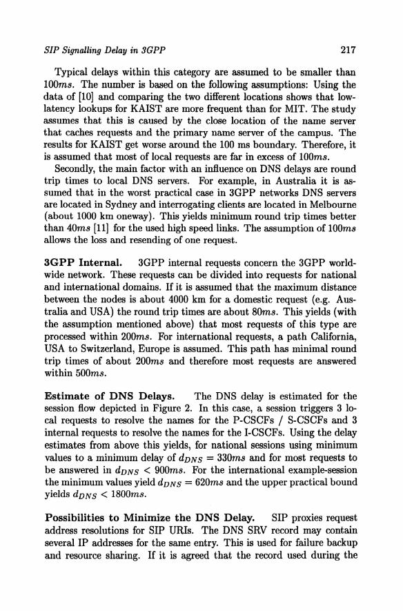
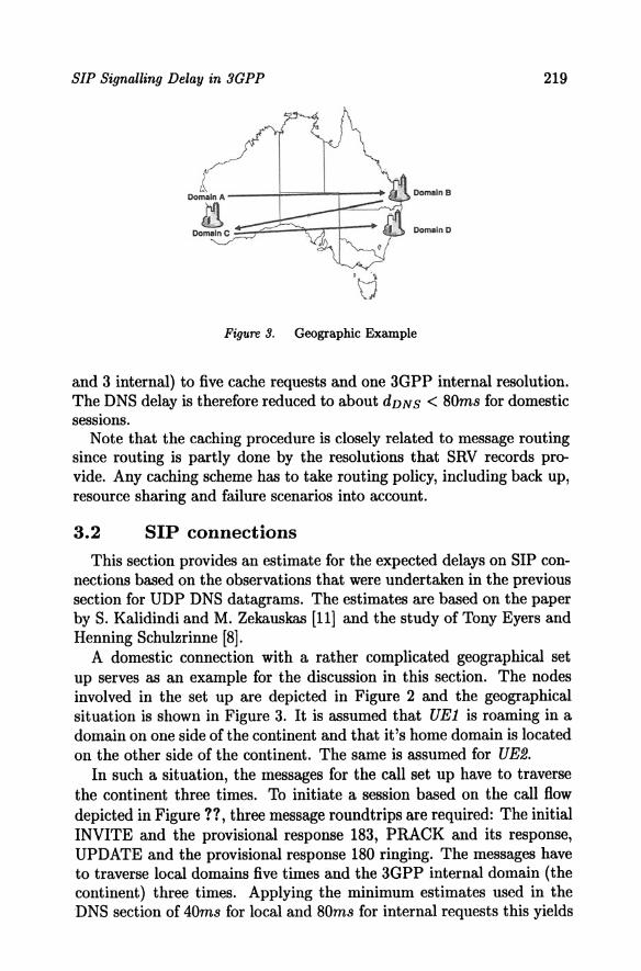
Figure 3. Geographie Example
and 3 internal) to five cache requests and one 3GPP internal resolution. The DNS delay is therefore reduced to about dvNS < 80ms for domestic sessions.
Note that the caching procedure is closely related to message routing since routing is partly done by the resolutions that SRV records provide. Any caching scheme has to take routing policy, including back up, resource sharing and failure seenarios into account.
3.2 SIP connections This section provides an estimate for the expected delays on SIP con
nections based on the observations that were undertaken in the previous section for UDP DNS datagrams. The estimates are based on the paper by S. Kalidindi and M. Zekauskas [11] and the study of Tony Eyers and Henning Schutzrinne [8].
A domestic connection with a rather complicated geographical set up serves as an example for the discussion in this section. The nodes involved in the set up are depicted in Figure 2 and the geographical situation is shown in Figure 3. It is assumed that UE1 is roaming in a domain on one side ofthe continent and that it's home domain is located on the other side of the continent. The same is assumed for UE2.
In such a situation, the messages for the call set up have to traverse the continent three times. To initiate a session based on the call flow depicted in Figure ?? , three message roundtrips are required: The initial INVITE and the provisional response 183, PRACK and its response, UPDATE and the provisional response 180 ringing. The messages have to traverse local domains five times and the 3GPP internal domain (the continent) three times. Applying the minimum estimates used in the DNS section of 40ms for local and 80ms for internal requests this yields
220
a single round-trip time of 440ms. The delay experienced on the SIP layer links for domestic session initiation for all three round trips yields 1320ms.
3.3 Estimate of expected Delays This section formulates an estimate of SID based on the results from
the previous sections. SID is the sum of the delays outlined in Section 1.3. These are the processing delay of 270ms which is based on nine SIP nodes included in a session flow. The 30ms per node includes the occurrence of six single message-processing delays: Three on the downstream and three on the upstream path. The same is true for the 210ms delay due to database requests in the seven intermediate nodes. This yields an overall delay of 1800ms plus BOrns due to the DNS system.
4. Simulation Results A discrete event simulator was used to simulate a SIP connection.
The message flow used is identical to Figure ?? . 100 000 Sessions were simulated with a Poisson arrival process with a mean arrivalrate of 1 session per second. For messages that have a SDP body (e.g. INVITE) it was assumed that the size of different messages is evenly distributed between 300 bytes and 700 bytes. Messages without SDP body are assumed to have a size between 200 bytes and 400 bytes. The servers have negative exponential service times with means of 10 ms. The links have propagation delays of 20 ms and 40 ms respectively. For INVITE requests, a SIP timer of 500 ms was used and for all other requests the timer was 800 ms.
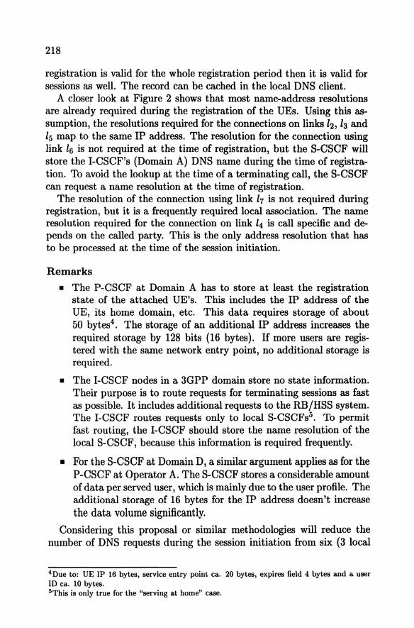
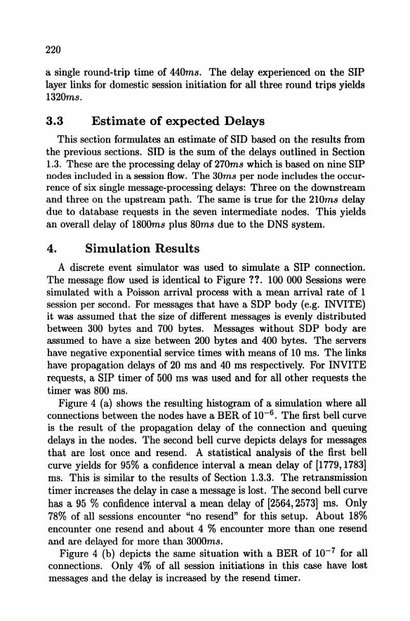
Figure 4 (a) shows the resulting histogram of a simulation where all Connections between the nodes have a BER of 10-6 • The first bell curve is the result of the propagation delay of the connection and queuing delays in the nodes. The second bell curve depicts delays for messages that are lost once and resend. A statistical analysis of the first bell curve yields for 95% a confidence interval a mean delay of [1779, 1783] ms. This is similar to the results of Section 1.3.3. The retransmission timer increases the delay in case a message is lost. The second bell curve has a 95 % confidence interval a mean delay of [2564, 2573) ms. Only 78% of all sessions encounter "no resend" for this setup. About 18% encounter one resend and about 4 % encounter more than one resend and are delayed for more than 3000ms.
Figure 4 (b) depicts the same situation with a BER of 10-7 for all connections. Only 4% of all session initiations in this case have lost messages and the delay is increased by the resend timer.

SIP Signalling Delay in 3GPP 221
Figure 4. Delay Histogram (a) BER = 10-6 and {b) BER = 10- 7
5. Conclusion For minimum delay assumptions SID yields 1880 milliseconds. This
figure is already close to the 3 seconds mean standard for ISDN calls. Long session initiation delays could cause considerable problems with the currently suggested set up of the SIP layer in 3GPP domains. Customer satisfaction is not the only concern. Problems can arise for the interoperation of 3GPP domains with existing telephone networks as already pointed out in [8] for SIP operating on the Internet. A further issue is bearer reservation. SignaHing messages trigger its set up and its tear down. Early barrier set up and delayed notification as well as delayed tear down can bind resources Ionger than they are actually required. For single connections, this may seem insignificant, but on a large scale this can result in significant utilization issues. Other implications of long delays include the actuality of state information such as user locations etc.
If 3G PP IM subsystem is to provide equivalent telephony services, SID can be compared with existing standards for ISDN signalling networks. For general real time multimedia applications no applicable standards exist. From the users' point of view, the acceptance level of delays depends on intermediate notification of progress.
For example, in typical computer applications, the GUI environment is used to display hourglasses or progress meters to indicate time to completion of a process. In classical telephone networks, the line is silent
222
between the instaut the user finishes dialling and the time a calling tone is received. The user gets no intermediate notification.
In next generation networks, such call progress notifications could be provided on a user level. Using this technique would allow the relaxation of the standards. Usersare used to waiting for today's computer applications that provide intermediate feedback about progress. This topic requires some research in the area of consumer satisfaction to support or dismiss some of the above suggestions.
6. Acknowledgements The authors would like to thank Ericsson AsiaPacificLab Australia
for their financial assistance for this work.
References [1] M. Handley, Henning Schulzrinne, E. Schooler, and Jonathan D. Rosenberg.
SIP: Session Initiation Protocol, March 1999. RFC 2543.
[2] Rosenberg, Schulzrinne, Camarillo, Johnston, Peterson, Sparks, Handley, and Schooler. SIP: Session Initiation Protocol. IETF, February 2002. Internet Draft <draft-ietf-sip-rfc2543bis-07.ps> (work in progress).
[3] Henning Schulzrinne and Jonathan D. Rosenberg. The Session Initiation Protocol: Internet-Centric Signaling. IEEE Communications Magazine, pages 134-141, October 2000.
[4] G.Camarillo, W. Marshall, and Jonathan Rosenberg. Integration of Resource Management and SIP. IETF, April 2002. Internet Draft <draft-ietf-sipmanyfolks-resource-07.ps > (work in progress).
[5] 3rd Generation Partnership Project. IP Multimedia (IM) Subsystem - Stage 2 {Release 5), July 2001. 3GPP TS 23.228 V5.1.0.
[6] Telecomunication Standardization Sector of ITU, Geneva, Switzerland. !TUT Recommendation E. 721: Network Grade of Service Parameters and Target Values for Circuit-Switched services in the evolving ISDN, 1991.
[7] AT & T. AT&T sets the Industry Standard for Network Reliability, September 2001. http:/ Jwww.att.com/network/standrd.html.
[8] Tony Eyers and Henning Schulzrinne. Predicting Internet Telephony Call Setup Delay. In IPTel 2000 (First IP Telephony Workshop), April 2000.
[9] P. Mockapetris. Domain Names - Implementation and Specification. IETF, November 1987. RFC 1035.
[10] Jaeyeon Jung Emil. DNS Performance and the Effectiveness of Caching. ACM SIGCOMM Internet Measurement Workshop 2001, 2001. http:/ /citeseer .nj.nec.com/ 44 7372.html.
[11] S. Kalidindi and M. Zekauskas. Surveyor: An Infrastructure for Internet Performance Measurements. June 1999. In INET'99.
![3G Gateway [gw-P25/M SP] - DEKOM · an IMS-ready SIP stack, supporting the up-to-date IETF and 3GPP RFCs implementations, including carrier grade SIP high availability and SIP Server](https://img.pdfslide.us/doc/110x75/5fd17c87ff8bf4158968f68d/3g-gateway-gw-p25m-sp-an-ims-ready-sip-stack-supporting-the-up-to-date-ietf.jpg)


![3GPP spec skeleton - arib.or.jp · 7 ELP Messages and Message Formats ... 7.4.26 Feature-List ... [21] 3GPP TS 25.413: "UTRAN Iu Interface RANAP signalling". [22] 3GPP2 A.S0014-D](https://img.pdfslide.us/doc/110x75/5b86778f7f8b9a8f318c9199/3gpp-spec-skeleton-ariborjp-7-elp-messages-and-message-formats-7426.jpg)