Embed Size (px)
Citation preview

Single VLANArchitecture
for Wireless LAN
Author:Alap Modi
Contributors:Colin JosephMichael WongPartha NarasimhanPeter ThornycroftShiv Mehra

January 2016 2
Copyright Information
© Copyright 2016 Hewlett Packard Enterprise Development LP
Open Source Code
This product includes code licensed under the GNU General Public License, the GNU Lesser General PublicLicense, and/or certain other open source licenses. A completemachine-readable copy of the source codecorresponding to such code is available upon request. This offer is valid to anyone in receipt of this information andshall expire three years following the date of the final distribution of this product version by Hewlett-PackardCompany. To obtain such source code, send a check or money order in the amount of US $10.00 to:
Hewlett-Packard Company
Attn: General Counsel
3000 Hanover Street
Palo Alto, CA 94304
USA
Please specify the product and version for which you are requesting source code. Youmay also request a copy ofthis source code free of charge at [email protected].

Single VLAN Architecture for WirelessLAN Contents | 3
Contents
Contents 3
Figures 6
Symbols 7
About this Guide 9
Acronyms 9
Scope 10
ReferenceMaterial 11
Introduction to Single VLAN Design 12
VLAN Pooling for WLAN 13
Use of VLANs 13
VLAN Pooling on EnterpriseWLAN 13
Key Considerations with VLAN Pooling 14
802.11 Frames do not Identify VLAN Tags 14
IPv6 SLAAC Breaks 15
Roaming Complexity 16
Inconsistent Utilization of VLANs from VLAN Pool 17
Single VLAN Design for WLAN 18
Single VLAN Design 18
Advantages of Single VLAN Design 19
Simple Design and Easy to Support 19
IPv6 SLAAC Challenges Solved 19
Roaming Becomes Simple 19
Address Efficiency 19
Key Considerations with Single VLAN Design 19
Limiting Large Amounts of Broadcast Multicast Traffic 19
Infrastructure to Support Large VLAN 20
Routers and Switches 20
DHCP Servers 20
Firewall Rules 20
Aruba's Single VLAN Design Solution 21
Optimizing ARP and DHCP Traffic 21

4 | Contents Single VLAN Architecture for WirelessLAN
Convert Broadcast ARP to Unicast 21
Suppress ARP 22
Optimize Duplicate Address Detection 23
Optimizing Broadcast andMulticast Traffic 25
Drop Broadcast andMulticast Traffic 25
AirGroup 26
IGMP Snooping and Dynamic Multicast Optimization 27
Optimizing ICMPv6 Traffic 27
Optimizing Router Advertisement and Router SolicitationMessages 27
Optimizing Duplicate Address DetectionMessages 27
Summary of Recommended Settings 28
Deployment Guidelines 29
Recommended Design 29
Guidelines 30
Deployment Steps 30
Recommendations 31
Validation 31
Configuration of Optimization Knobs 32
Convert Broadcast ARP Request to Unicast 32
CLI 32
WebUI 32
Suppress ARP 33
CLI 33
WebUI 33
Optimize Duplicate Address Detection 33
CLI 33
WebUI 33
Drop Broadcast and UnknownMulticast 33
CLI 33
WebUI 33
AirGroup 34
CLI 34
WebUI 34
IGMP Snooping and DMO 35
CLI 35

WebUI 35
Conclusion 36
Single VLAN Architecture for WirelessLAN Contents | 5

Single VLAN Architecture for WirelessLAN Figures | 6
Figures
Figure 1 VRD core technologies 10
Figure 2 WLAN design without VLAN pooling 14
Figure 3 WLAN design with VLAN pooling 14
Figure 4 Unicast and broadcast/multicast traffic onWLAN 15
Figure 5 IPv6 Stateless Address Auto-Configuration 16
Figure 6 Single VLAN design 18
Figure 7 Without converting broadcast ARP to unicast 22
Figure 8 Converting broadcast ARP to unicast 22
Figure 9 Without Suppressing ARP 23
Figure 10 With suppress ARP enabled 23
Figure 11 Without duplicate address detection 24
Figure 12 With duplicate address detection 24
Figure 13 Without Drop Broadcast andMulticast Traffic 25
Figure 14 With Drop Broadcast andMulticast Traffic 26
Figure 15 Large campus with the single VLAN design 29
Figure 16 Channel Utilization 31
Figure 17 Convert broadcast ARP request to unicast navigation 32
Figure 18 Convert broadcast ARP request to unicast checkbox 32
Figure 19 Suppress ARP navigation 33
Figure 20 Enable Suppress ARP checkbox 33
Figure 21 Drop broadcast and unknownmulticast navigation 33
Figure 22 Drop broadcast and unknownmulticast checkbox 34
Figure 23 AirGroup 34
Figure 24 IGMP navigation 35
Figure 25 Enable IGMP checkbox and Enable IGMP Snooping button 35
Figure 26 DMO checkbox and DMOThreshold field 35

Single VLAN Architecture for WirelessLAN Symbols | 7
Symbols
The table below describes the symbols used in the figures in this guide.
Description Symbol
Wireless Controller
Access Point
Layer 2 Switch
Layer 3 Switch
Router
Table 1: Symbols

8 | Symbols Single VLAN Architecture for WirelessLAN
Description Symbol
Servers/PBX
Wired Client - Desktop Computer
Wireless Client - Laptop
Wireless Client - Smart Phone
Table 1: Symbols
Single VLAN Architecture for WirelessLAN About thisGuide | 9
Chapter 1About this Guide
This chapter includes the following topics:
l Acronyms
l Scope
l ReferenceMaterial
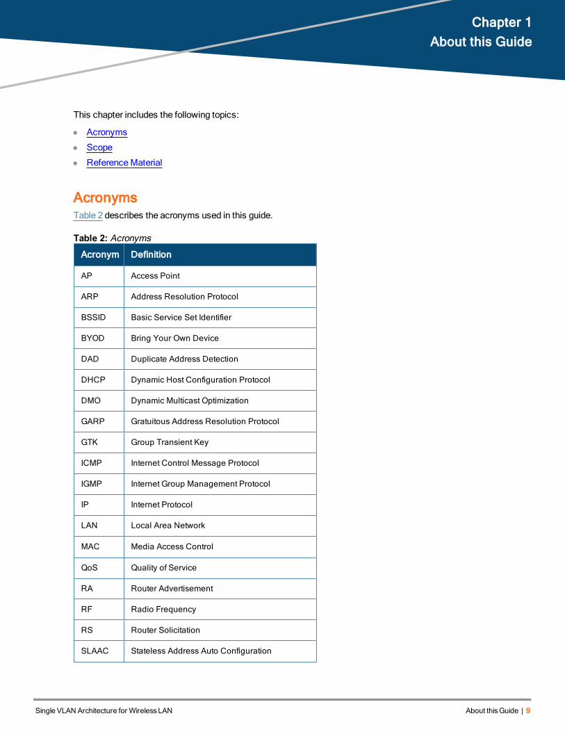
AcronymsTable 2 describes the acronyms used in this guide.
Acronym Definition
AP Access Point
ARP Address Resolution Protocol
BSSID Basic Service Set Identifier
BYOD Bring Your Own Device
DAD Duplicate Address Detection
DHCP Dynamic Host Configuration Protocol
DMO Dynamic Multicast Optimization
GARP Gratuitous Address Resolution Protocol
GTK Group Transient Key
ICMP Internet Control Message Protocol
IGMP Internet Group Management Protocol
IP Internet Protocol
LAN Local Area Network
MAC Media Access Control
QoS Quality of Service
RA Router Advertisement
RF Radio Frequency
RS Router Solicitation
SLAAC Stateless Address Auto Configuration
Table 2: Acronyms

10 | About thisGuide Single VLAN Architecture for WirelessLAN
Acronym Definition
SSID Service Set Identifier
VLAN Virtual Local Area Network
VRD Validated Reference Design
WLAN Wireless Local Area Network
Table 2: Acronyms
ScopeThe Aruba Validated Reference Design (VRD) is a series of technology deployment guides that include descriptionsof Aruba technology, recommendations for product selection, network design decisions, configuration steps, andbest practices. Together these guides comprise a referencemodel for understanding Aruba technology and designfrom common customer deployment scenarios.
The VRD series has four types of guides:
l Foundation: These guides explain the core technologies of an ArubaWLAN. The guides also describe differentaspects of planning, operation, and troubleshooting deployments.
l Base Design: These guides describe themost common deployment models, recommendations, andconfigurations.
l Application: These guides build on the base designs. These guides deliver specific information that is relevant todeploying particular applications such as voice, video or outdoor campus extension.
l Specialty deployments: These guides involve deployments in conditions that differ significantly from the commonbase design deployment models, such as high-density WLAN deployments.
Figure 1 VRD core technologies
This Single VLAN design guide is part of “Base Designs” guides within the VRD core technology series.
l It is designed for ArubaMobility Controllers running ArubaOS 6.4.3.4 and later.
l It does not cover the fundamental concepts of wireless networks. This guide assumes that the reader has aworking knowledge of ArubaWLAN architecture.
l This design guide focuses on a large campus deployment model wheremultiple buildings with contiguous radiofrequency (RF) are part of the campus.

Reference MaterialThis is a base designs guide, and therefore it will not cover the fundamental wireless concepts. Readers should havea good understanding of wireless concepts and the Aruba technology explained in the foundation-level guides.
l For information on ArubaMobility Controllers and deployment models, see the ArubaMobility Controllers andDeployment Models Validated Reference Design, available on the Aruba website athttp://www.arubanetworks.com/vrd
l The complete suite of Aruba technical documentation is available for download from the Aruba support site.These documents present complete, detailed feature and functionality explanations beyond the scope of theVRD series. The Aruba support site is located at: https://support.arubanetworks.com/
l Formore training on Aruba products, or to learn about Aruba certifications, visit the Aruba training and certificationpage on our website. This page contains links to class descriptions, calendars, and test descriptions:http://www.arubanetworks.com/support-services/training-services/
l Aruba hosts a user forum site and user meetings called Airheads. The forum contains discussions ofdeployments, products, and troubleshooting tips. Airheads Online is an invaluable resource that allows networkadministrators to interact with each other and Aruba experts. Please visit: http://community.arubanetworks.com/
Single VLAN Architecture for WirelessLAN About thisGuide | 11

Single VLAN Architecture for WirelessLAN Introduction to Single VLAN Design | 12
Chapter 2Introduction to Single VLAN Design
The growth of Wi-Fi in enterpriseWireless Local Area Network (WLAN) startedmore than a decade ago. Initially,people used wired networks as a primary medium to connect to networks, andWi-Fi was just an option. To support ahandful of devices connecting toWi-Fi, network administrators used to assign separate Virtual Local Area Network(VLAN) for wireless clients, whichmet the users’ needs.
With the launch of mobile devices in 2007, the use of Wi-Fi increased exponentially. As themobile devices did nothave Ethernet ports, Wi-Fi became the essential medium for connectivity. To support increased numbers of clientsonWLAN, network administrators started addingmore VLANs for wireless users, and VLAN pooling became apopular concept. Network administrators createdmultiple smaller subnets to reduce broadcast multicast trafficrather than increasing the size of the subnet.
Today the requirements for campus and enterpriseWLAN have changed quite a bit due to the following:
l Large number of consumer devices connecting to enterpriseWLAN.
l Increased use of IPv6 devices on enterpriseWLAN.
l Continuous roaming of mobile devices throughout the campus.
There are some challenges supporting these requirements with VLAN pooling. The challenges include: wirelessLocal Area Network (LAN) design and roaming complexity, controlling a large amount of broadcast multicast traffic,IPv6 Stateless Address Auto Configuration (SLAAC), and inconsistent use of VLANs from the VLAN Pool. Thus,network administrators need to find out a way to overcome these challenges.
At Aruba, we think using a Single VLAN design provides a great alternative to design enterpriseWireless LAN. Thisdocument discusses VLAN pooling in an enterpriseWLAN, what are the challenges related to it, and how a SingleVLAN architecture can help to address them. It also provides design and configuration guidelines to use with SingleVLAN architecture, addresses some of the concerns that network administrators may have with the single VLANdesign, and finally discusses migration strategy from VLAN Pooling to Single VLAN architecture.

Single VLAN Architecture for WirelessLAN VLAN Pooling for WLAN | 13
Chapter 3VLAN Pooling for WLAN
This chapter includes the following topics:
l Use of VLANs
l VLAN Pooling on EnterpriseWLAN
l Key Considerations with VLAN Pooling
Use of VLANsVLANs are a popular concept in the field of networking and there have beenmultiple reasons for networkadministrators to use VLANs. Here are a few common ones:
1. Limit broadcast domains by reducing the size of the subnet.
2. Segregate traffic for security - Not a very elegant way to provide security but sometimes that is the best option.
3. Quality of Service (QoS) - Really a way to segregate traffic, so that it can be queued properly even if not tagged.
4. Non-contiguous Internet Protocol (IP) space – Mostly the case where IPv4 public addresses are used for wirelessclients.
5. Simpler administration – Looking at the IPv4 address can tell you something about the user, the user’s group(employee, contractor, or guest), the location etc. However, IPv6 can be tricky.
VLAN Pooling on Enterprise WLANDue to the Bring Your OwnDevice (BYOD) trend, large numbers of consumermobile devices are connecting to theenterpriseWLAN. Network administrators need to ensure that there are enough IP addresses available to supportthese clients. On top of that clients are always roaming across the campus and as RF is contiguous throughout thecampus, clients are not going to renew their IP address.
The VLAN pooling feature allows the network administrator to assign a “pool” of VLANs to a class of users. Thisclass of users is mainly identified by the Service Set Identifier (SSID) and the location of the access points (APs).For example, as shown in Figure 3, a pool of VLANs consisting of VLANs 10, 20, and 30 can be assigned to all thewireless clients connecting to “Students” SSID in the campus. When a client connects to a network of thisconfiguration, the controller assigns a VLAN to the client from the configured pool. This VLAN derives from a hashalgorithm based on the client’s MAC address and the number of VLANs in the pool. The hash algorithm ensures thatevery time the client connects to the network via any AP to any controller, the controller assigns the same VLAN,thus maintaining the IP address of the client as it roams across the APs and controllers.

14 | VLAN Pooling for WLAN Single VLAN Architecture for WirelessLAN
Figure 2 WLAN design without VLAN pooling
Figure 3 WLAN design with VLAN pooling
Key Considerations with VLAN PoolingWhile VLAN Pooling has been a popular feature for enterpriseWLANs for many years, there are some challengeswith it:
l 802.11 Frames do not Identify VLAN Tags
l IPv6 SLAAC Breaks
l Roaming Complexity
l Inconsistent Utilization of VLANs from VLAN Pool
802.11 Frames do not Identify VLAN TagsOne of the reasons VLANs and smaller subnets are used in designing networks to reduce broadcast andmulticasttraffic. In the case of wired networks, switches and routers understand VLAN tags and thus restrict broadcast

domains to each VLAN only. However, when it comes to treating broadcast-multicast traffic for aWLAN, all theclients connected to a BSSID can hear broadcast-multicast traffic from all the VLANs being used on that SSID,irrespective of client’s actual VLAN. Thus, logically BSSID creates a broadcast domain.
Figure 4 Unicast and broadcast/multicast traffic onWLAN
Let us understand it in detail. In the example above, when a unicast packet for Client-1 in VLAN 10 comes to thecontroller, the controller forwards it to Client-1 via AP1. Over the air, when this frame is being sent to the client, it issent to the destinationMAC address, which is equal to Client-1’s MAC address. Similarly, when the unicast packetfor Client-2 in VLAN 20 comes to the controller, the controller forwards it to Client-2 via AP2 in a similar manner.
A problem occurs when themulticast or broadcast packet for Client-1 in VLAN 10 comes to the controller. Forexample, say the ARP packet for Client-1 comes to the controller. Assuming there are no optimizations done, ARPbeing a broadcast packet, by default the controller will forward it to all the APs where clients in VLAN 10 exists. TheARP packet will go to AP1 and AP2. When the packet comes to AP2, AP sends it out in the air with the destinationMAC address as the broadcast MAC (FF:FF:FF:FF:FF:FF). As Client 2 and 3 are connected to the same BSSID,Client 2 and 3 both will receive it, irrespective of which VLANs they are part of.
So why is this concerning? Because, the use of smaller subnets / VLANs:
l To restrict broadcast domain does not completely hold true forWLAN as it depends on BSSID/Channel as well.
l To segregate traffic is also not the case as we explained in the example.
IPv6 SLAAC BreaksWhen network administrators started implementing IPv6 with Stateless Address Auto Configuration (SLAAC) onWLAN, they came across a problem where clients were getting IP addresses from a different VLAN than the onethat the controller assigned.
A problem occurs when the clients on the same AP belong to different VLANs. This can occur when theWLAN usesVLAN pooling, IP Mobility, or the role-based VLAN derivation rule. (This problem will not occur if all the clients on anAP belong to same VLAN.)
Single VLAN Architecture for WirelessLAN VLAN Pooling for WLAN | 15

16 | VLAN Pooling for WLAN Single VLAN Architecture for WirelessLAN
Figure 5 IPv6 Stateless Address Auto-Configuration
A newly authenticated client is assigned to a VLAN. The network infrastructure knows about the VLAN, but theclient does not know it until it gets an IP address from the Dynamic Host Configuration Protocol (DHCP). In IPv6SLAAC there is no DHCP, so the client does not know its assigned VLAN.
To obtain an IPv6 address, the client must find its parent router and obtain a 64-bit prefix, then add its 64-bit interfaceID to form a 128-bit address. To find its router the client may send a broadcast Neighbor Discovery Protocol RouterSolicitation (RS) or wait for a periodic Router Advertisement (RA).
Where an AP serves members of more than one IPv6 VLAN, each router configured with a VLAN will advertise RAs,usingmulticast. Un-assigned clients will respond to the first RA they see since 802.11 frames do not carry anyVLAN tag information. If the first router belongs to a client’s assigned VLAN, all is well; it will receive an address inthat VLAN range. However, if the first RA is for a different VLAN, it will get the wrong address and the network willnot route its source address to other destinations, so traffic will be ‘black-holed’. On top of that, clients can havemultiple IPv6 addresses. If the client hears RAs onmultiple VLANs, it will assignmultiple IPv6 addresses, wheresome of them will be invalid.
Roaming ComplexityIn an enterprise environment, based on the size of the campus, theremight bemultiple controllers to server APs andclients across the campus. If an SSID is available throughout the campus, then the client will not attempt to get anew IP address when it roams from one controller to another. To support seamless roaming of clients throughout thecampus, network administrators need to configure VLAN (L2) or IP (L3) mobility.
In the case of VLAN Mobility, client VLANs are extended across all the controllers (as shown in Figure 3), whichrequires them to be configured across multiple switches in the path of the controllers and creates a big broadcastdomain.
In the case of IP Mobility, different controllers will have different VLANs for wireless clients. However, to avoidclients renewing an IP address, you need to configure IP Mobility, which requires the setup of an IP address or GREtunnels between all the controllers serving the campus.
Both VLAN and IP Mobility have proven to increase complexity of the design and scalability challenges for largecampus networks.
Inconsistent Utilization of VLANs from VLAN PoolMost vendors use hash algorithms to assign a VLAN from the VLAN pool to the wireless client. As this hashalgorithm is mainly based on the client’s MAC address and number of VLANs in the pool, there have beenmanysituations where some VLANs from the VLAN pool are completely exhausted due to a large number of clients inthem, while other VLANs are quite empty.
Many vendors use round robin or even algorithms to achieve equal use of all the VLANs in the VLAN Pool.Over time, these algorithms have matured to work well in large campus networks.
Looking at all of the above challenges with VLAN Pooling, here at Aruba, we think that there is an another way todesign a next generation of WLAN with just one flat large VLAN.
Single VLAN Architecture for WirelessLAN VLAN Pooling for WLAN | 17

Single VLAN Architecture for WirelessLAN Single VLAN Design for WLAN | 18
Chapter 4Single VLAN Design for WLAN
This chapter includes the following topics:
l Single VLAN Design
l Advantages of Single VLAN Design
l Key Considerations with Single VLAN Design
Single VLAN DesignThe Single VLAN design refers to one large subnet to serve all the clients connecting to an SSID in the campusenvironment with contiguous RF. Controller and tunneled APs make it possible to scale to larger subnets in therange of /22 to /16.
The Single VLAN design is simple and smart. It can greatly reduce the complexity of theWLAN design, and itaddresses the IPv6, DHCP, and roaming challenges seen with VLAN pooling. At the same time, you canmeet all ofthe requirements of the wireless LAN using the Single VLAN design. Large universities can use themaximumadvantage of this design with their thousands of wireless clients across a large campus with contiguous RF followedby large enterprises with multiple buildings at a location.
The Single VLAN design recommends to use the same VLAN throughout the campus with contiguous RF. If youhavemultiple buildings in different locations (for example, school districts or corporate branches spread acrossdifferent cities or towns), then you should use different VLANs and subnets.
The Single VLAN architecture recommends using one large subnet for all the clients connecting to an SSID.However, you can use separate VLANs for clients connecting to separate SSIDs. Ideally, in the campus WLAN, youshould use separate VLANs for employee and guest SSIDs.
Lastly, wired and wireless clients should not be sharing the same VLAN. Use separate VLANs for wired clients and,if needed, usemultiple smaller subnets to restrict broadcast domain for wired devices. The Single VLAN architectureis for wireless LAN only, as the controller has a lot of visibility and control over wireless users, but none for wireddevices. The obvious problems related to large VLANs on wired networks still apply.
Figure 6 Single VLAN design

19 | Single VLAN Design for WLAN Single VLAN Architecture for WirelessLAN
Advantages of Single VLAN DesignReasons for using a single VLAN architecture include the following.
Simple Design and Easy to SupportWith just one large subnet for all the wireless clients connecting to an SSID, the network administrator does not needto configuremultiple VLANs, DHCP scopes, extend VLANs across multiple devices, and configure redundancy fordefault gateways in each VLAN.
On top of that, the network administrator does not need to configure VLAN mobility or IP mobility for clients roamingacross different controllers. As the client VLAN is going to be the same, the client keeps using the same IP address.
As wireless LAN design becomes simple, it is very easy for network administrators to support this design. If at thesame time some issues come up, it is very easy to troubleshoot it as well. Network administrators do not need tofigure out which VLAN the client falls into, try to isolate an issue related to just that VLAN, or network wide, and soon.
IPv6 SLAAC Challenges SolvedWith the single VLAN design, there will not bemultiple RAs coming from IPv6 routers. Thus, there is no issue of theclient getting the wrong v6 address.
Roaming Becomes SimpleNomatter where the client roams, either on a different AP on the same controller or on a different controller, the clientdoes not need to change its IP address. The network administrator does not need to configure Layer 2 or Layer 3roaming on the controller. This solves the roaming complexity for the network administrator.
Address EfficiencyAs there will be just one VLAN, there is no issue of some VLANs getting completely exhausted while other VLANsstaying less utilized. In large campus environments with thousands of users, this helps to avoid the issue of clientsnot getting IP addresses due to some VLANs being completely exhausted.
Key Considerations with Single VLAN DesignMany things come to a network administrator’s mind before using a large subnet. Some of themost commonquestions that come up are:
Limiting Large Amounts of Broadcast Multicast TrafficThis is the first thing that comes to the network administrator’s mind when thinking about using the single VLANdesign. As we discussed in section 3.3.1, in the case of WLAN, there is not a very big difference between VLANPooling and the Single VLAN design in terms of the amount of broadcast andmulticast traffic.
In the case of the Aruba controller and tunneled APs, the controller is a central point who knows about all theassociated clients, their IP addresses, andMAC addresses, to which AP they are connected, what role they are in,and what type of traffic they are allowed. Thus, the controller canmake intelligent decisions on which packet needsto go to which clients to reduce unnecessary traffic in the air.
To do that ArubaOS has features and built-in intelligence that can reduce the amount of broadcast andmulticasttraffic. Chapter 5 in this document covers all the features available in ArubaOS to intelligently optimize broadcastandmulticast traffic.

Infrastructure to Support Large VLANTo support a large VLAN, other devices on the network also need to be capable. Some of themost commonconcerns are related to:
Routers and Switches
Most of the time the wireless client VLAN is configured as Layer 2 on the Aruba controller and uplink switch. Theuplink router is configured as Layer 3 interface working as default gateway for that VLAN. While using large VLANs,the ARP table on the router can be very large depending on how many clients are connected to theWLAN. Thus,network administrators should find out any limitations on the router and address them accordingly.
The same goes for switches. Although the controller uplink switch does not need to handle ARP entries, thebridge/MAC address table entries can be very large. The network administrator should consider this.
DHCP Servers
In the case of single VLAN design, the DHCP server needs to be able to support large DHCP scopes, as big as /16.Many Linux based DHCP servers are not capable of this. Thus, the network administrator needs to ensure that theDHCP server can handle a large DHCP scope.
At the same time, the DHCP server needs to be powerful enough to lease out IP addresses quickly. During a failoversituation, it becomes essential.
Firewall Rules
Formost of the enterprise networks, existing firewall rules are based on IP subnets. There aremany networkadministrators still entrenched in this way of thinking. Even inside the network, routing, access control, andQoS aredone based on the VLANs and IP subnet through routers and legacy firewalls. Obviously next generation firewallsare user and application centric and are reasonably deployed at the Internet gateway and data centers for largeenterprise customers.
With the Single VLAN Design, all the traffic of wireless clients is in one subnet only. Hence user and applicationcentric firewalls are needed to apply proper firewall rules. Onemore option is to use the Aruba Controller's built instateful firewall to manage firewall policies for wireless clients.
Single VLAN Architecture for WirelessLAN Single VLAN Design for WLAN | 20

Single VLAN Architecture for WirelessLAN Aruba'sSingle VLAN Design Solution | 21
Chapter 5Aruba's Single VLAN Design Solution
The biggest concern that network administrators may have with the single VLAN design is about how to restrictbroadcast andmulticast traffic. In the case of a large subnet with thousands of users, there will be a large amount ofbroadcast multicast traffic. This broadcast andmulticast traffic can affect client performance if not restrictedproperly by the wireless controller. At the same time, not all the broadcast andmulticast traffic should be dropped bythe wireless controller or network infrastructure, otherwise some of the basic functionalities like VRRP, IPv6,DHCP, ARP, MDNS, etc. may break. In the case of Aruba controllers, tunneled APs, and software intelligence builtinto ArubaOS, thesemake it possible to deploy the single VLAN design. In this chapter, we will look into differentknobs available in ArubaOS to limit broadcast andmulticast traffic.
This chapter includes the following topics:
l Optimizing ARP and DHCP Traffic
l Optimizing Broadcast andMulticast Traffic
l Optimizing ICMPv6 Traffic
l Summary of Recommended Settings
Optimizing ARP and DHCP TrafficWhen using large subnets ARP and DHCP traffic can significantly impact the performance of aWLAN. A singleARP packet in a VLAN will be flooded to all the AP tunnels where that VLAN exists. Thinking in a real worldscenario, if you have 1000 APs on the controller, and if an ARP packet comes to the controller (from wired side orfrom one of the wireless clients) on a wireless client VLAN, then that ARP packet will be flooded to all 1000 APtunnels and sent out in the air. This can affect the performance of wireless clients and thus the broadcast filter ARPknob should be used.
A similar behavior will be seen for DHCP packets as well.
Gratuitous ARP can also impact theWLAN performance. Whenever a client sends aGARP frame, that frame goesto all other wired and wireless clients. Each client receiving this GARP framewill update its ARP cache entry for it.In the network where there are thousands of clients sending GARP, we noticed problems with mobile devices andlaptops where they ran out of their ARP table limits as they do not support too big of a size of ARP table. Mostlyclients support ARP table entries in the range varying from 512 to 4000 entries or less. Thus after a certain point,clients started losing default-gateway entries and thus showing connectivity issues.
The Aruba controller has features that can help to reduce the amount of ARP and DHCP packets flooded to wirelessclients.
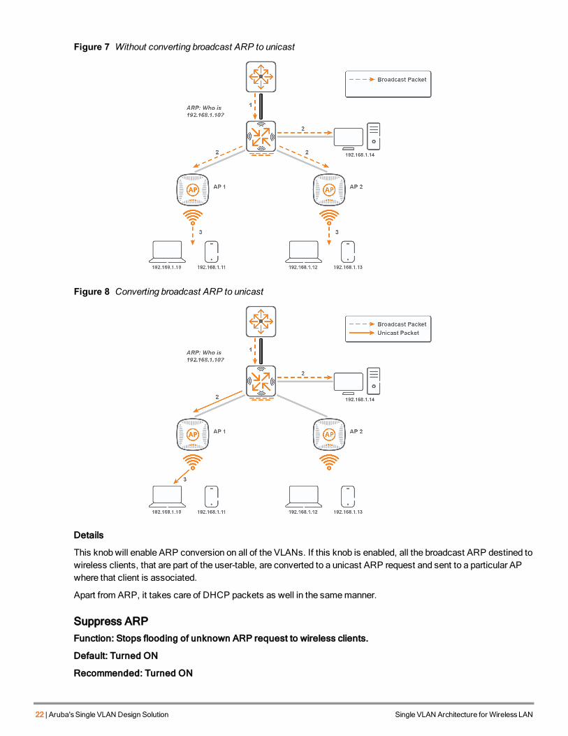
Convert Broadcast ARP to UnicastFunction: Converts broadcast ARP and DHCP packets to unicast before sending to wireless clients.
Default: Turned ON
Recommended: Turned ON
22 | Aruba'sSingle VLAN Design Solution Single VLAN Architecture for WirelessLAN
Figure 7 Without converting broadcast ARP to unicast
Figure 8 Converting broadcast ARP to unicast
Details
This knob will enable ARP conversion on all of the VLANs. If this knob is enabled, all the broadcast ARP destined towireless clients, that are part of the user-table, are converted to a unicast ARP request and sent to a particular APwhere that client is associated.
Apart from ARP, it takes care of DHCP packets as well in the samemanner.
Suppress ARPFunction: Stops flooding of unknown ARP request to wireless clients.
Default: Turned ON
Recommended: Turned ON

Figure 9 Without Suppressing ARP
Figure 10 With suppress ARP enabled
Details
This knob will stop flooding of “unknown” ARP requests to AP tunnels (tunnel and d-tunnel mode only). The unknownARP request will still be flooded out of LAN ports, wired AP ports, and split-tunnel VAPs.
Optimize Duplicate Address DetectionFunction: Controls the flooding of Gratuitous ARP and IPv6 Duplicate Address Detection frames to wirelessclients.
Default: Turned ON
Single VLAN Architecture for WirelessLAN Aruba'sSingle VLAN Design Solution | 23

24 | Aruba'sSingle VLAN Design Solution Single VLAN Architecture for WirelessLAN
Recommended: Turned ON
Figure 11 Without duplicate address detection
Figure 12 With duplicate address detection
Details
Broadcast Filter ARP and Suppress ARP features take care of known and unknown ARP frames but not GARP. The“Optimize Duplicate Address Detection” feature stops forwarding GARP and IPv6 DAD frames to wireless clients.However, there is an exception to this. If the GARP or DAD frame is coming from the router (default gateway), theywill still send it to all the wireless clients as that is very important information for clients. This especially helps whencustomers have default gateway redundancy. If the active gateway goes down, then the standby gateway will startowning the gateway IP and send out the GARP frame to update clients about the new IP toMedia Access Control(MAC) address mapping.

Optimizing Broadcast and Multicast TrafficOnce ARP and DHCP packets are converted to unicast, the next step is to restrict broadcast andmulticast thatmight be generated as a part of some applications running on the client devices. Most common applications useeither NetBIOS, MDNS or DLNA based services, which aremulticast based. The Aruba controller has features thatcan completely drop all of these broadcast multicast traffic or allow specific types of traffic by converting it tounicast.
Many companies or universities havemulticast video streams running in their network for business and educationalpurpose. Theremight be other custom applications, which run onmulticast. Tomeet these requirements, the Arubacontroller provides knobs to optimizemulticast traffic over the air.
Drop Broadcast and Multicast TrafficFunction: Stops flooding of broadcast and multicast traffic to wireless clients.
Default: Turned OFF
Recommended: Turned ON
Figure 13 Without Drop Broadcast andMulticast Traffic
Single VLAN Architecture for WirelessLAN Aruba'sSingle VLAN Design Solution | 25

26 | Aruba'sSingle VLAN Design Solution Single VLAN Architecture for WirelessLAN
Figure 14 With Drop Broadcast andMulticast Traffic
Details
ArubaOS has “Drop Broadcast andMulticast traffic” knob in Virtual-AP profile. When enabled, all of the broadcastandmulticast traffic on theWLAN will be dropped.
Drop Broadcast Multicast knob will drop broadcast ARP and DHCP packets if “Convert broadcast ARP tounicast” knob is not enabled.
Even if a multicast based application needs to work on the WLAN, it is safe to enable the “Drop broadcastMulticast” knob. The upcoming sections give instructions on how to permit the known multicast traffic evenwhen this knob is enabled.
AirGroupFunction: Allows mdns and upnp traffic by converting them to unicast.
Default: Turned Off
Recommended: Turn ON to allow mdns and universal plug and play traffic.
Details
While we drop the broadcast–multicast traffic in the air, in enterprise or campus deployments DLNA, MDNS, andother zero-configuration services are essential. To allow such services for airplay and Chromecast kind ofapplications, ArubaWLAN with AirGroup technology enables context aware access to DLNA, Apple Bonjour, andother shared devices without constrainingWLAN performance.
To understand in detail how the AirGroup feature works, please review:
l Aruba User Guide
https://support.arubanetworks.com/Documentation/tabid/77/DMXModule/512/Default.aspx?EntryId=8863
l AirGroup Deployment Guide
http://community.arubanetworks.com/aruba/attachments/aruba/unified-wired-wireless-access/15478/1/ArubaAirGroup-6136-DG.pdf

IGMP Snooping and Dynamic Multicast OptimizationFunction: Keeps track of clients subscribed to multicast stream and converts multicast packets to unicastbefore sending it to wireless clients.
Default: Disabled (both IGMP snooping and DMO)
Recommended: Enable if multicast streaming needs to be allowed on Wi-Fi
Details
Dynamic Multicast Optimization (DMO) knob converts multicast packets to unicast and transmits it at higher unicastrate over the air.
IGMP snooping or IGMP proxy needs to be enabled for DMO to work.
Multicast stream should be prioritized by configuring uplink ACL and correct WMM parameter to match DSCPvalues.
Optimizing ICMPv6 TrafficIn the case of IPv6 (Internet Control Message Protocol (ICMP)), RA, RS, and DAD are themain control messagesthat go to the IPv6multicast address. If they are not optimized properly, then it can affect client performance thesameway as IPv4multicast traffic.
Optimizing Router Advertisement and Router Solicitation MessagesIn the case of IPv6, clients can auto configure the IPv6 address either by listening to periodic RA messages or bysending out RS messages when they come up and then in turn getting RA from the IPv6 router. All these RA and RSmessages are sent to specific multicast addresses, so that all the routers and clients can hear them. However, atthe same time it can affect the wireless client performance.
In the case of the Aruba controller, if all the wireless clients fall into the same VLAN (Single VLAN design), thenperiodic RAs are sent as it is – multicast packets as impact on the client performance is not toomuch. However, ifVLAN pooling is used, then depending on the number of VLANs in the pool, periodic RAs can flood the network. Toavoid that, the controller intercepts RAs, converts them to unicast packets, and sends them to all the clients in thatVLAN.
For the RS message, even though it goes on amulticast address, the controller does not put that frame into APtunnels; thus, they do not go to wireless clients. When the response (RA) comes back from the default gateway, thecontroller just forwards that packet to that particular client that sent out the RS message.
Thus, ArubaOS is by default optimized to handle RA and RS messages without enabling any special features.
Optimizing Duplicate Address Detection MessagesThe purpose of DAD packets are the same as GARP packets in the case of IPv4. Whenever the client gets an IPaddress, either by DHCPv6 or by SLAAC, it sends out DAD packets to inform others about its IP address. As DADpackets are sent on the IPv6multicast address, all the clients on that VLAN can hear them. Especially in the case ofthe Single VLAN design, if each and every client sends out a DAD packet when it gets the IPv6 address, and if allother clients in that VLAN listen to it, then clients will need to handle a large number of ARP tables. There is alimitation to how many ARP table entries the client can handle. This depends on the type of client. It is usually in therange of 512 to 4000 entries. If you havemore than 4000 clients on your campus and if all of them send DADpackets, then a situation can occur, where the client runs out of its ARP cache entries and thus faces intermittentconnectivity issues.
Single VLAN Architecture for WirelessLAN Aruba'sSingle VLAN Design Solution | 27

28 | Aruba'sSingle VLAN Design Solution Single VLAN Architecture for WirelessLAN
To address that the Aruba controller has the “Optimize Duplicate Address Detection” feature, which works asdescribed in Optimize Duplicate Address Detection..
Summary of Recommended SettingsTable 3 summarizes the recommended settings.
Table 3: Summary of Recommended Settings
Feature / Setting DefaultSetting
RecommendedSetting
Note
Convert broadcast ARPto Unicast
ON ON Converts broadcast ARP and DHCP packets toUnicast before forwarding to wireless clients
Suppress ARP ON ON Stops flooding of unknown ARP request towireless clients
Optimize DuplicateAddress Detection
ON ON Controls the flooding of Gratuitous ARP and IPv6Duplicate Address Detection frames to wirelessclients
Drop Broadcast andMulticast traffic
OFF ON Stops flooding of broadcast and multicast traffic towireless clients
AirGroup OFF ON* * Turn it on to allow MDNS and UPnP traffic
IGMP Snooping andDynamic MulticastOptimization
OFF ON* * Turn it ON to allow multicast streaming onWLAN

Single VLAN Architecture for WirelessLAN Deployment Guidelines | 29
Chapter 6Deployment Guidelines
This chapter includes the following topics:
l Recommended Design
l Guidelines
l Deployment Steps
l Recommendations
l Validation
Recommended DesignA typical large campus with the single VLAN design will look like Figure 15 below.
Figure 15 Large campus with the single VLAN design
As shown in the diagram:

30 | Deployment Guidelines Single VLAN Architecture for WirelessLAN
l APs are connected at the access layer to the access switch. As all of the client traffic is tunneled between thecontroller and the AP, the client VLAN is not needed on the access switch.
l Local controllers are connected to the distribution switch in large campuses, as they will havemultiple controllersserving different parts of the campus.
l Themaster controller is typically located in the data center, connected to the core switch.
l The client VLAN is Layer 2 to the Aruba controller and distribution switches. The core switch or firewall will havea Layer 3 interface for the client VLAN.
Guidelines1. The single VLAN design is intended for wireless clients connecting APs in the same campus with contiguous RF.
If RF is not contiguous, then it is completely fine to use different VLANs/subnets for different RF domains.
a. If the client can roam from one building to another building in the campus without dropping off from SSID, thena single VLAN should be used in that campus.
The typical use cases using the Single VLAN design include university campuses, large enterpriseheadquarters, and hospitals with multiple buildings.
b. If the customer has multiple buildings and offices spread across different geographic locations, then RF is notgoing to be contiguous. Thus, they should use separate VLANs.
The typical use case is branch offices or home offices.
c. Customers must not use VLAN derivation by user role or server-rule. If clients connected to the same SSIDare in different VLANs, then the behavior is the same as VLAN pooling. Thus, all the concerns mentionedrelated to VLAN pooling will be applied to such a design.
2. The large subnet is for wireless clients connected to the same SSID only. Use different VLANs for differentSSIDs (for example, Employee vs. Guest SSID).
3. If customers havemultiple controllers serving a campus network with contiguous RF, then they should extendthe client VLAN all the way back to their core switch, router, or firewall where the default gateway exists.
4. Customers using the Single VLAN designmust ensure that their uplink switches, router, or firewalls are able tosupport the required number of ARP andMAC address table entries depending on the subnet size as discussedin section 4.3.
5. Ensure that the DHCP server can support DHCP scope as large as the size of the client VLAN.
Deployment StepsCustomers who are planning to use the single VLAN design for their wireless clients should follow the steps below:
1. Find out the number of wireless clients on the network (in the same campus with contiguous RF) and add 20%more to incorporate future growth. AirWave or any other network management system can help.
2. Decide the size of the subnet and find out IP space that can accommodate it.
3. Create this new VLAN on your controller, distribution switch, and core switch/router/firewall as needed.
4. Create a DHCP scope for this new VLAN on your DHCP server and configure the IP helper address on yourswitch or router as needed.
5. Enable optimization on theWLAN controller to drop unnecessary broadcast multicast traffic. Refer to Chapter 6about all of the knobs and their recommended settings.
6. Assign a new VLAN to the Virtual AP profile on the controller during themaintenance window. Usuallyuniversities do it over the summer. For enterprise customers, they need to do it during themaintenance window.
7. Monitor the network for the next few weeks and then retire the older VLAN scopes if everything is working fine.Make sure there are no performance, roaming, connectivity, DHCP, IPv6, or firewall policies related issues.Once that is assured, older VLAN scopes can retire.

Recommendations1. Use ArubaOS 6.4.3.4 or higher.
2. Size of the subnet – Typically in the range of /22 to /16.
3. Distribution Switch – Need to support a large number of MAC address table entries based on the size of thesubnet selected.
4. Core Switch or Firewall (default gateway) – Needs to support a large number of ARP table entries depending onthe size of the subnet selected.
5. DHCP server – Needs to support DHCP scope as large as the size of the subnet selected for wireless clients.
ValidationVerify the RF/Channel utilization in a Network Management System like AirWave. If there is a lot of broadcast andmulticast traffic flooding to wireless clients, then the RF utilization will be significantly high. Normally on 2.4 GHzchannel utilization will be between 20 to 40%, and on 5GHZ it will be between 10 to 30%. Of course the numbermayvary if you are in amultivalent facility or due to another source of interference.
Figure 16 below provides an example of channel utilization.
Figure 16 Channel Utilization
Single VLAN Architecture for WirelessLAN Deployment Guidelines | 31

Single VLAN Architecture for WirelessLAN Configuration of Optimization Knobs | 32
Chapter 7Configuration of Optimization Knobs
This chapter provides information about enabling optimization knobs on the Aruba controller as discussed in Chapter5.
This chapter includes the following topics:
l Convert Broadcast ARP Request to Unicast
l Suppress ARP
l Optimize Duplicate Address Detection
l Drop Broadcast and UnknownMulticast
l AirGroup
l IGMP Snooping and DMO
Convert Broadcast ARP Request to Unicast
CLI(config)# wlan virtual-ap <profile-name>(Virtual AP profile <profile-name>)# broadcast-filter ARP
WebUI
Figure 17 Convert broadcast ARP request to unicast navigation
Figure 18 Convert broadcast ARP request to unicast checkbox

33 | Configuration of Optimization Knobs Single VLAN Architecture for WirelessLAN
Suppress ARP
CLI(config)# interface vlan <id>(config-subif)#supress-arp
WebUI
Figure 19 Suppress ARP navigation
Figure 20 Enable Suppress ARP checkbox
Optimize Duplicate Address Detection
CLI(config)# firewall optimize-dad-frames
WebUINot available from theWebUI.
Drop Broadcast and Unknown Multicast
CLI(config)# wlan virtual-ap <profile-name>(Virtual AP profile <profile-name>)# broadcast-filter ALL
WebUI
Figure 21 Drop broadcast and unknownmulticast navigation

Figure 22 Drop broadcast and unknownmulticast checkbox
AirGroupRefer to the following for more details:
l AirGroup Deployment Guide
http://community.arubanetworks.com/aruba/attachments/aruba/unified-wired-wireless-access/15478/1/ArubaAirGroup-6136-DG.pdf
l Aruba User Guide
https://support.arubanetworks.com/Documentation/tabid/77/DMXModule/512/Default.aspx?EntryId=8863
CLI(Config): airgroup enable/disable
WebUI
Figure 23 AirGroup
Single VLAN Architecture for WirelessLAN Configuration of Optimization Knobs | 34

35 | Configuration of Optimization Knobs Single VLAN Architecture for WirelessLAN
IGMP Snooping and DMO
CLI(config)# interface vlan <id>(config-subif)#ip igmp snooping
(config)# wlan virtual-ap <profile-name>(Virtual AP profile <profile-name>)#dynamic-mcast-optimization(Virtual AP profile <profile-name>)#dynamic-mcast-optimization-thresh 80
WebUI
Figure 24 IGMP navigation
Figure 25 Enable IGMP checkbox and Enable IGMP Snooping button
Figure 26 DMO checkbox and DMOThreshold field

Single VLAN Architecture for WirelessLAN Conclusion | 36
Chapter 8Conclusion
As discussed in this document, there has been a traditional way of designing wired and wireless networks usingmultiple VLANs and VLAN pooling. Although VLAN pooling has been working out fine for many years, it has somedesign complexities and challenges especially with IPv6. At the same time, the Single VLAN design provides a greatalternative tomake design simple and avoidmany complexities associated with VLAN pooling as discussed in thisdocument.
We think there are going to be cases and requirements where VLAN pooling needs to be used and it should be used,but at the same time for many other requirements (especially universities, public Wi-Fi, and large enterprisecampuses) the Single VLAN design should be considered.
The Aruba controller and AP has features to control and optimize broadcast andmulticast traffic associated with alarge VLAN. AirGroup and Dynamic Multicast Optimization features make it possible to usemulticast basedapplications and streaming on wireless without affecting the performance of the wireless clients. The Arubacontroller takes care of optimizingmulticast traffic related to IPv6 as well.
Network architects should consider this simplified design and follow the guidelines and recommendations providedin this guide to implement it successfully.


![Aruba Mobility Master and VMC Installation Guidecommunity.arubanetworks.com/aruba/attachments/aruba/unified-wired...[root@localhost~]#cat/etc/sysconfig/network-scripts/ifcfg-br2 DEVICE=br2](https://img.pdfslide.us/doc/110x75/5b1ec9a17f8b9a7f2f8bebae/aruba-mobility-master-and-vmc-installation-rootlocalhostcatetcsysconfignetwork-scriptsifcfg-br2.jpg)