Embed Size (px)
Citation preview
NEW Product
1
Single-phase Overcurrent/Undercurrent Relay
K8AK-AW
Ideal for Current Monitoring for Industrial Facilities and Equipment.• Monitor for overcurrents and undercurrents simultaneously.
Separate settings and outputs supported for overcurrents and undercurrents.
• Use commercially available CTs (CT current on secondary side: 0 to 1 A or 0 to 5 A).
• Manual resetting and automatically resetting supported by one Relay.
• Startup lock and operating time can be set separately.• Two sets of SPDT output contacts, 5 A at 250 VAC (resistive
load).• Output status can be monitored using LED indicator.• Inputs are isolated from the power supply.
Ordering InformationList of Models
* The K8AK-AW3 is designed to be used in combination with an OMRON K8AC-CT200L Current Transformer (CT). (Direct input is not possible.)
Accessory (Order Separately)OMRON CT Commercially Available CTs*
* If you use a commercially available CT, do not exceed the overload capacity of the K8AK-AW2.
Refer to Safety Precautions on page 11.Refer to page 10 for commonly asked questions.
For the most recent information on models that have been certified for safety standards, refer to your OMRON website.
Setting range Power supply voltage Model
2 to 20 mA AC/DC10 to 100 mA AC/DC50 to 500 mA AC/DC
24 VAC/DC K8AK-AW1 24 VAC/DC
100 to 240 VAC K8AK-AW1 100-240 VAC
0.1 to 1 A AC/DC0.5 to 5 A AC/DC
24 VAC/DC K8AK-AW2 24 VAC/DC
100 to 240 VAC K8AK-AW2 100-240 VAC
10 to 100 A AC*20 to 200 A AC*
24 VAC/DC K8AK-AW3 24 VAC/DC
100 to 240 VAC K8AK-AW3 100-240 VAC
Appearance Input range Applicable Relay Model
10 to 100 A AC, 20 to 200 A AC K8AK-AW3 K8AC-CT200L
Appearance CT current on secondary side Applicable Relay
0 to 1 A AC,0 to 5 A AC K8AK-AW2
K8AK-AW
2
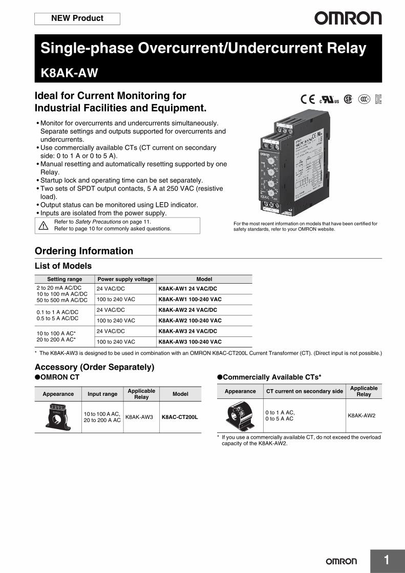
Ratings and SpecificationsInput Range
*1 The range is selected using connected terminals.*2 The K8AK-AW3 is designed to be used in combination with an OMRON K8AC-CT200L Current Transformer (CT). (Direct input is not possible.)
Model Range*1 Connection terminals Setting range Input impedance Input type Overload capacity
K8AK-AW1
0 to 20 mA AC/DC I1-COM 2 to 20 mA AC/DC10 to 100 mA AC/DC50 to 500 mA AC/DC
Approx. 5 Ω Direct input
Continuous input at 120% of maximum input.1 s at 150%
0 to 100 mA AC/DC I2-COM Approx. 1 Ω Direct input
0 to 500 mA AC/DC I3-COM Approx. 0.2 Ω Direct input
K8AK-AW20 to 1 A AC/DC I1-COM
0.1 to 1 A AC/DC0.5 to 5 A AC/DC
Approx. 0.12 Ω (Load: 0.5 VA) Direct input or
commercially available CT0 to 5 A AC/DC I2-COM Approx. 0.02 Ω
(Load: 1.5 VA)
K8AK-AW3
0 to 100 A AC I2-COM
10 to 100 A AC*2
20 to 200 A AC*2
--- OMRON CT Continuous input at 120% with an OMRON CT (K8AC-CT200L).30 s at 200%1 s at 600%* CT capacity on primary
side.
0 to 200 A AC I3-COM --- OMRON CT
K8AK-AW
3
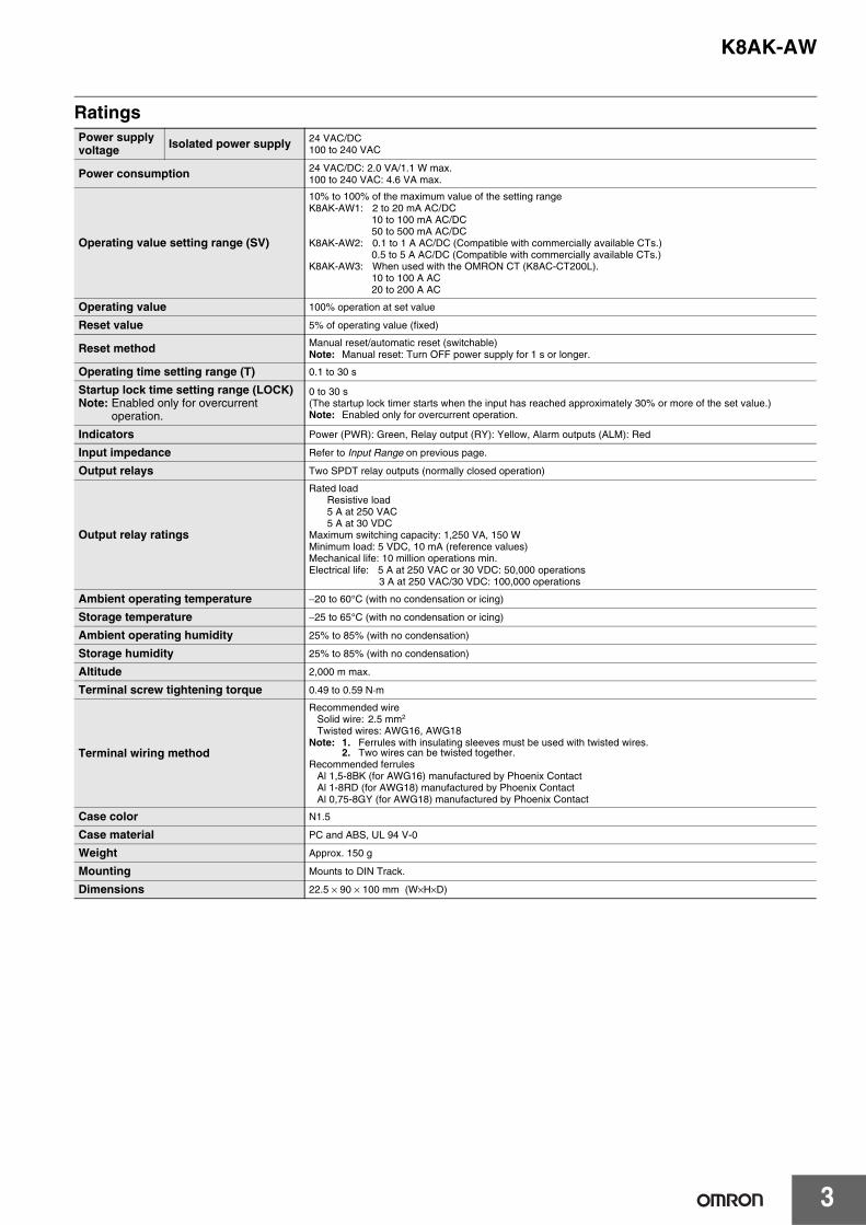
RatingsPower supply voltage Isolated power supply 24 VAC/DC
100 to 240 VAC
Power consumption 24 VAC/DC: 2.0 VA/1.1 W max.100 to 240 VAC: 4.6 VA max.
Operating value setting range (SV)
10% to 100% of the maximum value of the setting rangeK8AK-AW1: 2 to 20 mA AC/DC
10 to 100 mA AC/DC50 to 500 mA AC/DC
K8AK-AW2: 0.1 to 1 A AC/DC (Compatible with commercially available CTs.)0.5 to 5 A AC/DC (Compatible with commercially available CTs.)
K8AK-AW3: When used with the OMRON CT (K8AC-CT200L).10 to 100 A AC20 to 200 A AC
Operating value 100% operation at set value
Reset value 5% of operating value (fixed)
Reset method Manual reset/automatic reset (switchable)Note: Manual reset: Turn OFF power supply for 1 s or longer.
Operating time setting range (T) 0.1 to 30 s
Startup lock time setting range (LOCK)Note: Enabled only for overcurrent
operation.
0 to 30 s(The startup lock timer starts when the input has reached approximately 30% or more of the set value.)Note: Enabled only for overcurrent operation.
Indicators Power (PWR): Green, Relay output (RY): Yellow, Alarm outputs (ALM): Red
Input impedance Refer to Input Range on previous page.
Output relays Two SPDT relay outputs (normally closed operation)
Output relay ratings
Rated loadResistive load5 A at 250 VAC5 A at 30 VDC
Maximum switching capacity: 1,250 VA, 150 WMinimum load: 5 VDC, 10 mA (reference values)Mechanical life: 10 million operations min.Electrical life: 5 A at 250 VAC or 30 VDC: 50,000 operations
3 A at 250 VAC/30 VDC: 100,000 operations
Ambient operating temperature −20 to 60°C (with no condensation or icing)
Storage temperature −25 to 65°C (with no condensation or icing)
Ambient operating humidity 25% to 85% (with no condensation)
Storage humidity 25% to 85% (with no condensation)
Altitude 2,000 m max.
Terminal screw tightening torque 0.49 to 0.59 N·m
Terminal wiring method
Recommended wireSolid wire: 2.5 mm2
Twisted wires: AWG16, AWG18Note: 1. Ferrules with insulating sleeves must be used with twisted wires.
2. Two wires can be twisted together.Recommended ferrules
Al 1,5-8BK (for AWG16) manufactured by Phoenix ContactAl 1-8RD (for AWG18) manufactured by Phoenix ContactAl 0,75-8GY (for AWG18) manufactured by Phoenix Contact
Case color N1.5
Case material PC and ABS, UL 94 V-0
Weight Approx. 150 g
Mounting Mounts to DIN Track.
Dimensions 22.5 × 90 × 100 mm (W×H×D)
K8AK-AW
4
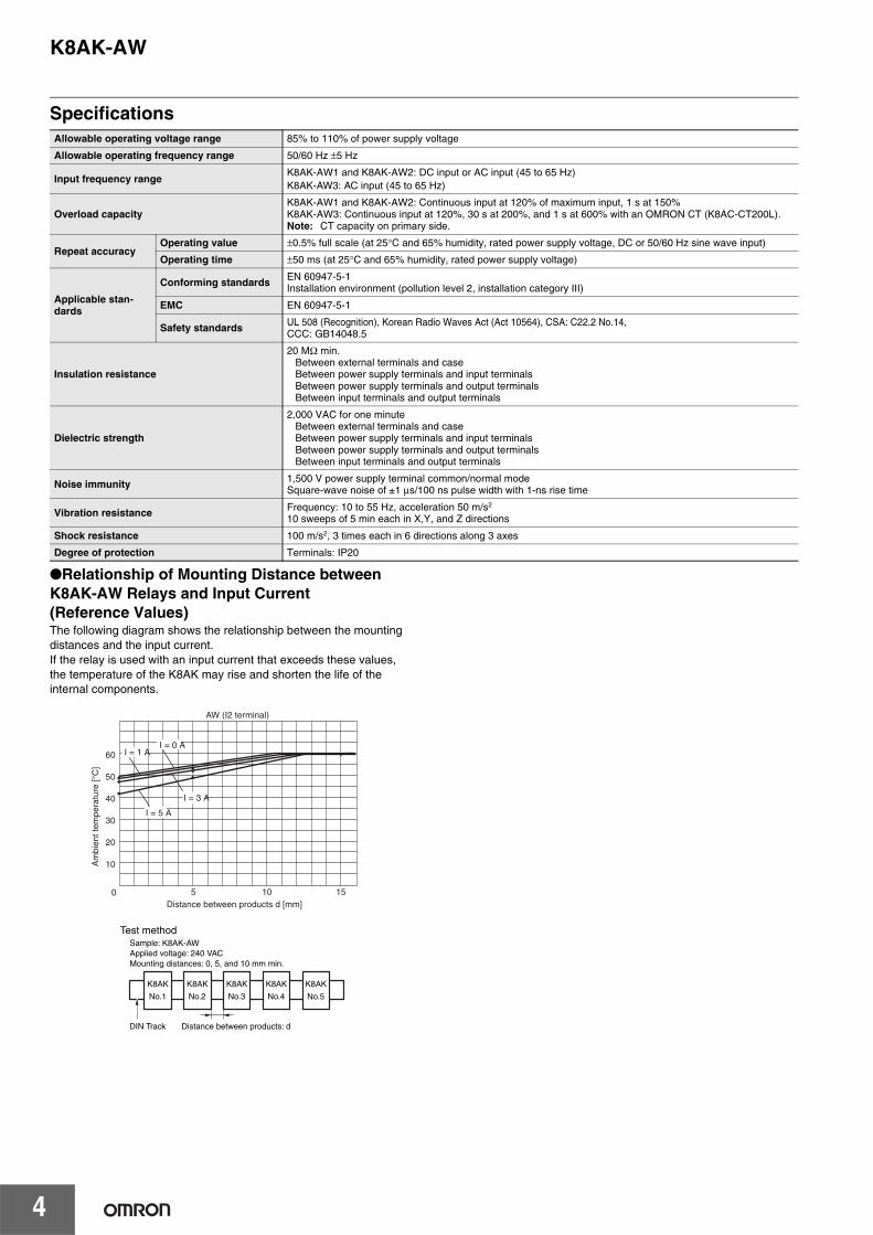
SpecificationsAllowable operating voltage range 85% to 110% of power supply voltage
Allowable operating frequency range 50/60 Hz ±5 Hz
Input frequency rangeK8AK-AW1 and K8AK-AW2: DC input or AC input (45 to 65 Hz)K8AK-AW3: AC input (45 to 65 Hz)
Overload capacityK8AK-AW1 and K8AK-AW2: Continuous input at 120% of maximum input, 1 s at 150%K8AK-AW3: Continuous input at 120%, 30 s at 200%, and 1 s at 600% with an OMRON CT (K8AC-CT200L).Note: CT capacity on primary side.
Repeat accuracyOperating value ±0.5% full scale (at 25°C and 65% humidity, rated power supply voltage, DC or 50/60 Hz sine wave input)
Operating time ±50 ms (at 25°C and 65% humidity, rated power supply voltage)
Applicable stan-dards
Conforming standards EN 60947-5-1Installation environment (pollution level 2, installation category III)
EMC EN 60947-5-1
Safety standards UL 508 (Recognition), Korean Radio Waves Act (Act 10564), CSA: C22.2 No.14, CCC: GB14048.5
Insulation resistance
20 MΩ min.Between external terminals and caseBetween power supply terminals and input terminalsBetween power supply terminals and output terminalsBetween input terminals and output terminals
Dielectric strength
2,000 VAC for one minuteBetween external terminals and caseBetween power supply terminals and input terminalsBetween power supply terminals and output terminalsBetween input terminals and output terminals
Noise immunity 1,500 V power supply terminal common/normal modeSquare-wave noise of ±1 µs/100 ns pulse width with 1-ns rise time
Vibration resistance Frequency: 10 to 55 Hz, acceleration 50 m/s2
10 sweeps of 5 min each in X,Y, and Z directions
Shock resistance 100 m/s2, 3 times each in 6 directions along 3 axes
Degree of protection Terminals: IP20
AW (I2 terminal)
0
10
60
50
40
30
20
5 10 15Distance between products d [mm]
I = 5 A
I = 3 A
I = 1 AI = 0 A
Am
bien
t tem
pera
ture
[°C
]
K8AK
No.3
K8AK
No.2
K8AK
No.1
K8AK
No.4
K8AK
No.5
DIN Track Distance between products: d
Sample: K8AK-AWApplied voltage: 240 VAC Mounting distances: 0, 5, and 10 mm min.
Test method
Relationship of Mounting Distance between K8AK-AW Relays and Input Current (Reference Values)The following diagram shows the relationship between the mounting distances and the input current.If the relay is used with an input current that exceeds these values, the temperature of the K8AK may rise and shorten the life of the internal components.
K8AK-AW
5
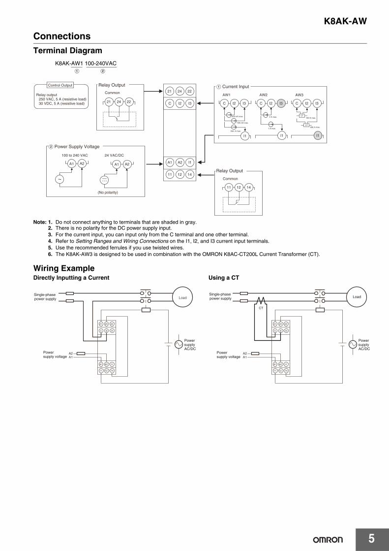
ConnectionsTerminal Diagram
Note: 1. Do not connect anything to terminals that are shaded in gray.2. There is no polarity for the DC power supply input.3. For the current input, you can input only from the C terminal and one other terminal.4. Refer to Setting Ranges and Wiring Connections on the I1, I2, and I3 current input terminals.5. Use the recommended ferrules if you use twisted wires.6. The K8AK-AW3 is designed to be used in combination with the OMRON K8AC-CT200L Current Transformer (CT).
Wiring ExampleDirectly Inputting a Current Using a CT
K8AK-AW1 100-240VACA B
Control Output
Relay output250 VAC, 5 A (resistive load)30 VDC, 5 A (resistive load)
A Current Input
AW1
Relay Output
Common
B Power Supply Voltage
100 to 240 VAC 24 VAC/DC
(No polarity)
A1 A2 I1
11 12 14
Relay Output
Common
500 mA max.
100 mA max.
20m A max.
AW2
5 A max.
1 A max.
AW3
100 A max.CT
CT200 A max.
21 24 22
C I2 I3
A1 A2 A1 A2
C I2 I3 C I2 I3C I2 I3
I1 I1 I1
21 24 22
11 12 14
21 22
C I2 I3
11 12
Load
14
A1 A2 I1
A1A2
24
Single-phase power supply
Power supply voltage
Power supply AC/DC
21 22
C I2 I3
11 12 14
A1 A2 I1
A1A2
CT
24
Single-phase power supply Load
Power supply voltage
Power supply AC/DC
K8AK-AW
6
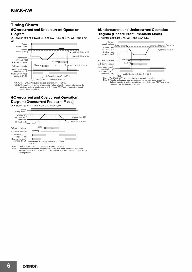
Timing ChartsOvercurrent and Undercurrent Operation DiagramDIP switch settings: SW3 ON and SW4 ON, or SW3 OFF and SW4 OFF
Overcurrent and Overcurrent Operation Diagram (Overcurrent Pre-alarm Mode)DIP switch settings: SW3 ON and SW4 OFF.
Undercurrent and Undercurrent Operation Diagram (Undercurrent Pre-alarm Mode)DIP switch settings: SW3 OFF and SW4 ON.
Input
Note 1. The K8AK-AW@ output contacts are normally operative.Note 2. The startup lock prevents unnecessary alarms from being generated during the
unstable period when the power is first turned ON. There is no contact output during timer operation.
t
Flashing LitFlashing Lit
Hysteresis: Fixed at 5%
Hysteresis: Fixed at 5%
AL1 alarm indicator
AL2 alarm indicator
Overcurrent (AL1) contacts (11-14)
Undercurrent (AL2) contacts (21-24)
Overcurrent set value (AL1)
Undercurrent set value (AL2)
Power supply voltage
t: Operating time (0.1 to 30 s)
LOCKLOCK: Startup lock time (0 to 30 s)
tt: Operating time (0.1 to 30 s)
Note 1. The K8AK-AW@ output contacts are normally operative.Note 2. The startup lock prevents unnecessary alarms from being generated during the
unstable period when the power is first turned ON. There is no contact output during timer operation.
Flashing Lit
Flashing Lit
Hysteresis: Fixed at 5%
Hysteresis: Fixed at 5%
AL1 alarm indicator
AL2 alarm indicator
Overcurrent (AL1) contacts (11-14)
Overcurrent set value (AL2)
Overcurrent (AL2) contacts (21-24)
Overcurrent set value (AL1)
Input
Power supply voltage
LOCK: Startup lock time (0 to 30 s)LOCK
Note 1. The K8AK-AW@ output contacts are normally operative.Note 2. The startup lock prevents unnecessary alarms from being generated
during the unstable period when the power is first turned ON. There is no contact output during timer operation.
Lit
Flashing Lit
Hysteresis: Fixed at 5%
Hysteresis: Fixed at 5%
AL1 alarm indicator
AL2 alarm indicator
Undercurrent (AL1) contacts (11-14)
Undercurrent set value (AL2)
Input
Undercurrent (AL2) contacts (21-24)
Undercurrent set value (AL1)
Power supply voltage
LOCK: Startup lock time (0 to 30 s)LOCK
Flashing
K8AK-AW
7
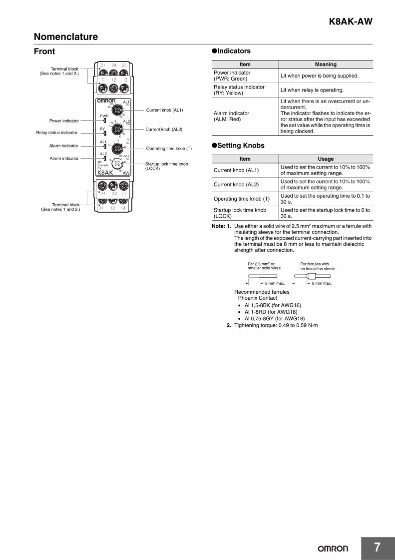
NomenclatureFront Indicators
Setting Knobs
Note: 1. Use either a solid wire of 2.5 mm2 maximum or a ferrule with insulating sleeve for the terminal connection.The length of the exposed current-carrying part inserted into the terminal must be 8 mm or less to maintain dielectric strength after connection.
Recommended ferrulesPhoenix Contact• Al 1,5-8BK (for AWG16)• Al 1-8RD (for AWG18)• Al 0,75-8GY (for AWG18)
2. Tightening torque: 0.49 to 0.59 N·m
Power indicator
Relay status indicator
Current knob (AL1)
Operating time knob (T)
Startup lock time knob(LOCK)
Alarm indicator
Terminal block (See notes 1 and 2.)
Terminal block (See notes 1 and 2.)
Alarm indicator
Current knob (AL2)
Item Meaning
Power indicator (PWR: Green) Lit when power is being supplied.
Relay status indicator (RY: Yellow) Lit when relay is operating.
Alarm indicator (ALM: Red)
Lit when there is an overcurrent or un-dercurrent. The indicator flashes to indicate the er-ror status after the input has exceeded the set value while the operating time is being clocked.
Item Usage
Current knob (AL1) Used to set the current to 10% to 100% of maximum setting range.
Current knob (AL2) Used to set the current to 10% to 100% of maximum setting range.
Operating time knob (T) Used to set the operating time to 0.1 to 30 s.
Startup lock time knob (LOCK)
Used to set the startup lock time to 0 to 30 s.
For 2.5 mm2 or smaller solid wires
For ferrules with an insulation sleeve.
8 mm max. 8 mm max.
K8AK-AW
8
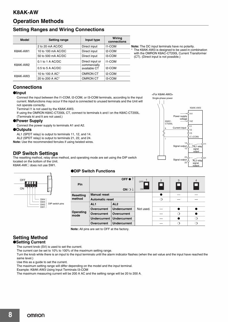
Operation MethodsSetting Ranges and Wiring Connections
ConnectionsInput
Connect the input between the I1-COM, I2-COM, or I3-COM terminals, according to the input current. Malfunctions may occur if the input is connected to unused terminals and the Unit will not operate correctly.Terminal I1 is not used by the K8AK-AW3.If using the OMRON K8AC-CT200L CT, connect to terminals k and l on the K8AC-CT200L. (Terminals kt and lt are not used.)
Power SupplyConnect the power supply to terminals A1 and A2.
OutputsAL1 (SPDT relay) is output to terminals 11, 12, and 14.AL2 (SPDT relay) is output to terminals 21, 22, and 24.
Note: Use the recommended ferrules if using twisted wires.
DIP Switch SettingsThe resetting method, relay drive method, and operating mode are set using the DIP switch located on the bottom of the Unit.K8AK-AW@ does not use SW1.
Setting MethodSetting Current
The current knob (SV) is used to set the current.The current can be set to 10% to 100% of the maximum setting range.Turn the knob while there is an input to the input terminals until the alarm indicator flashes (when the set value and the input have reached the same level.)Use this as a guide to set the current.The maximum setting range will differ depending on the model and the input terminal.Example: K8AK-AW3 Using Input Terminals I3-COMThe maximum measuring current will be 200 A AC and the setting range will be 20 to 200 A.
Model Setting range Input type Wiring connections
K8AK-AW1
2 to 20 mA AC/DC Direct input I1-COM Note: The DC input terminals have no polarity.* The K8AK-AW3 is designed to be used in combination
with the OMRON K8AC-CT200L Current Transformer (CT). (Direct input is not possible.)
10 to 100 mA AC/DC Direct input I2-COM
50 to 500 mA AC/DC Direct input I3-COM
K8AK-AW20.1 to 1 A AC/DC Direct input or
commercially available CT
I1-COM
0.5 to 5 A AC/DC I2-COM
K8AK-AW310 to 100 A AC* OMRON CT I2-COM
20 to 200 A AC* OMRON CT I3-COM
<For K8AK-AW3>
Load
Current input
Signal output AL1 relay signal output
Single-phase power
Power supplyvoltage
K8AK-AW3
K8AC-CT200L
C (COM)
A1
A2
I1
I2
I3
1114
l
k
12
2124
22Signal output AL2 relay
signal output
DIP switch pinsSW3
ON
OFF
SW2SW1
SW4
DIP Switch Functions
Note: All pins are set to OFF at the factory.
Pin
OFF ↑
ON ↓
Resetting method
Manual reset
Not used.
--- ---
Automatic reset --- ---
Operating mode
AL1 AL2
Overcurrent Undercurrent ---
Overcurrent Overcurrent ---
Undercurrent Undercurrent ---
Overcurrent Undercurrent ---
1OFF
ON
2 3 4
K8AK-AW
9
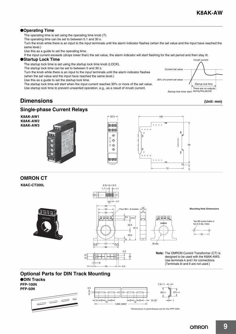
Operating TimeThe operating time is set using the operating time knob (T).The operating time can be set to between 0.1 and 30 s.Turn the knob while there is an input to the input terminals until the alarm indicator flashes (when the set value and the input have reached the same level.)Use this as a guide to set the operating time.If the input current exceeds (drops lower than) the set value, the alarm indicator will start flashing for the set period and then stay lit.
Startup Lock TimeThe startup lock time is set using the startup lock time knob (LOCK).The startup lock time can be set to between 0 and 30 s.Turn the knob while there is an input to the input terminals until the alarm indicator flashes (when the set value and the input have reached the same level.)Use this as a guide to set the startup lock time.The startup lock time will start when the input current reaches 30% or more of the set value.Use startup lock time to prevent unwanted operation, e.g., as a result of inrush current.
Dimensions (Unit: mm)
Single-phase Current Relays
OMRON CT
Optional Parts for DIN Track Mounting
Inrush current
Current set value
30% of current set value
Startup lock timer start
Startup lock time
There are no outputs during this period.
22.5
90
100
72 5
K8AK-AW1K8AK-AW2K8AK-AW3
1.8
764.1
1010
5.9
5.2
20
Two M5 screw holes or two 5.5-dia. holes
57 30 dia.14.514.5
6
8.5
50
33.5
34.581.5
13.5
86
54
6311
4.7
Four M4 × 6 screws17
20
9.3
1.71.7
9.3
76
Mounting Hole Dimensions
Note: The OMRON Current Transformer (CT) is designed to be used with the K8AK-AW3. Use terminals k and l for connections.(Terminals kt and lt are not used.)
K8AC-CT200L
*Dimensions in parentheses are for the PFP-50N.
4.5
15 25 2510 10
1,000 (500)*
25 25 15 (5)*
35±0.3
7.3±0.15
27±0.15
1
DIN TracksPFP-100NPFP-50N
K8AK-AW
10
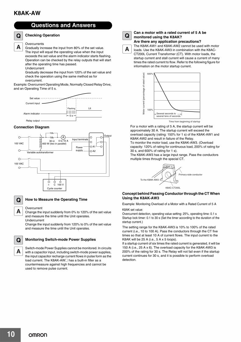
Checking Operation
OvercurrentsGradually increase the input from 80% of the set value.The input will equal the operating value when the input exceeds the set value and the alarm indicator starts flashing. Operation can be checked by the relay outputs that will start after the operating time has passed.UndercurrentGradually decrease the input from 120% of the set value and check the operation using the same method as for overcurrent.
Example: Overcurrent Operating Mode, Normally Closed Relay Drive, and an Operating Time of 5 s.
Connection Diagram
How to Measure the Operating Time
OvercurrentChange the input suddenly from 0% to 120% of the set value and measure the time until the Unit operates.UndercurrentChange the input suddenly from 120% to 0% of the set value and measure the time until the Unit operates.
Monitoring Switch-mode Power Supplies
Switch-mode Power Supplies cannot be monitored. In circuits with a capacitor input, including switch-mode power supplies, the input capacitor recharge current flows in pulse form as the load current. The K8AK-AW@ has a built-in filter as a countermeasure against high frequencies and cannot be used to remove pulse current.
Can a motor with a rated current of 5 A be monitored using the K8AK?Are there any application precautions?The K8AK-AW1 and K8AK-AW2 cannot be used with motor loads. Use the K8AK-AW3 in combination with the K8AC-CT200L Current Transformer (CT). With motor loads, the startup current and stall current will cause a current of many times the rated current to flow. Refer to the following figure for information on the motor startup current.
For a motor with a rating of 5 A, the startup current will be approximately 30 A. The startup current will exceed the overload capacity (rating: 150% for 1 s) of the K8AK-AW1 and K8AK-AW2 and result in failure of the Relay. To monitor the motor load, use the K8AK-AW3. (Overload capacity: 120% of rating for continuous load, 200% of rating for 30 s, and 600% of rating for 1 s).The K8AK-AW3 has a large input range. Pass the conductors multiple times through the special CT.
Concept behind Passing Conductor through the CT When Using the K8AK-AW3
Example: Monitoring Overload of a Motor with a Rated Current of 5 A
K8AK set value: Overcurrent detection, operating value setting: 25%, operating time: 0.1 sStartup lock timer: 0.1 to 30 s (Set the timer according to the duration of the startup current.)
The setting range for the K8AK-AW3 is 10% to 100% of the rated current (i.e., 10 to 100 A). Pass the conductors through the CT five times so that at least 10 A of current flows. The input current to the K8AK will be 25 A (i.e., 5 A x 5 loops).If a startup current of six times the rated current is generated, it will be 150 A (i.e., 25 A x 6). The overload capacity for the K8AK-AW3 is 200% of the rating for 30 s. The Relay will not fail even if the startup current continues for 30 s, and it is possible to perform overload detection.
Questions and Answers
Q
Set value
Current input
Alarm indicator
Relay output
Flashing Lit
5 s
100 VAC
100 VAC
30 Ω 0 to 10 AA
A1
A2
± C 100 V
Variable autotransformer
Input terminals
Powersupply
Output
Cycle counter
400 W (two in parallel)
Q
Q
Q
Mot
or c
urre
nt (
perc
enta
ge o
f rat
ed v
alue
)
Several seconds to several tens of seconds
Time from beginning of startup
100%
500%
K8AC-CT200L
Primary-side conductor
To the K8AK-AW3
K8AK-AW
11
Safety Precautions
Be sure to read the precautions for all models in the website at the following URL: http://www.ia.omron.com/.
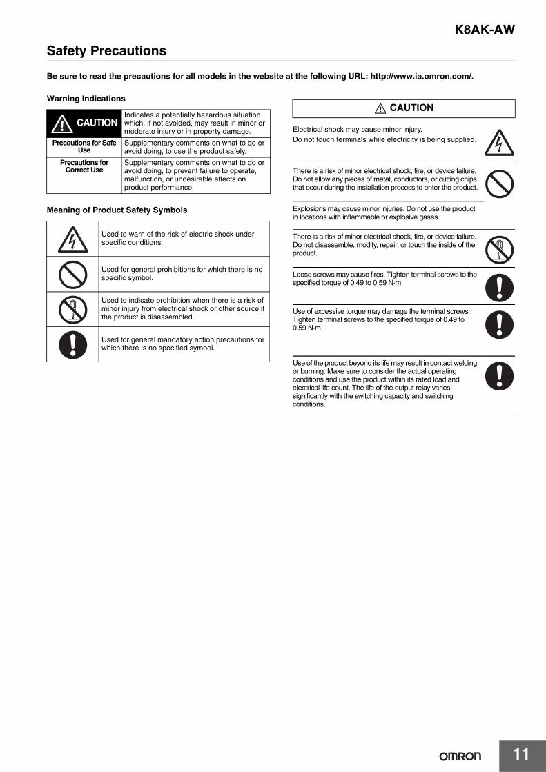
Warning Indications
Meaning of Product Safety Symbols
Electrical shock may cause minor injury.Do not touch terminals while electricity is being supplied.
There is a risk of minor electrical shock, fire, or device failure. Do not allow any pieces of metal, conductors, or cutting chips that occur during the installation process to enter the product.
Explosions may cause minor injuries. Do not use the product in locations with inflammable or explosive gases.
There is a risk of minor electrical shock, fire, or device failure. Do not disassemble, modify, repair, or touch the inside of the product.
Loose screws may cause fires. Tighten terminal screws to the specified torque of 0.49 to 0.59 N·m.
Use of excessive torque may damage the terminal screws. Tighten terminal screws to the specified torque of 0.49 to 0.59 N·m.
Use of the product beyond its life may result in contact welding or burning. Make sure to consider the actual operating conditions and use the product within its rated load and electrical life count. The life of the output relay varies significantly with the switching capacity and switching conditions.
CAUTIONIndicates a potentially hazardous situation which, if not avoided, may result in minor or moderate injury or in property damage.
Precautions for Safe Use
Supplementary comments on what to do or avoid doing, to use the product safely.
Precautions for Correct Use
Supplementary comments on what to do or avoid doing, to prevent failure to operate, malfunction, or undesirable effects on product performance.
Used to warn of the risk of electric shock under specific conditions.
Used for general prohibitions for which there is no specific symbol.
Used to indicate prohibition when there is a risk of minor injury from electrical shock or other source if the product is disassembled.
Used for general mandatory action precautions for which there is no specified symbol.
CAUTION
K8AK-AW
12
1. Do not use or store the product in the following locations.• Locations subject to water or oil
• Outdoor locations or under direct sunlight
• Locations subject to dust or corrosive gases (particularly sulfurizing gases, ammonia, etc.)
• Locations subject to rapid temperature changes
• Locations prone to icing and dew condensation
• Locations subject to excessive vibration or shock
• Locations subject to wind and rain
• Locations subject to static electricity and noise
• Habitats of insects or small animals
2. Use and store the product in a location where the ambient temperature and humidity are within the specified ranges. If applicable, provide forced cooling.
3. Mount the product in the correct direction.4. Check terminal polarity when wiring and wire all connections
correctly. The power supply terminals do not have polarity.5. Do not wire the input and output terminals incorrectly.6. Make sure the power supply voltage and loads are within the
specifications and ratings for the product.7. Make sure the crimp terminals for wiring are of the specified size.8. Do not connect anything to terminals that are not being used.9. Use a power supply that will reach the rated voltage within 1
second after the power is turned ON.10.Keep wiring separate from high voltages and power lines that
draw large currents. Do not place product wiring in parallel with or in the same path as high-voltage or high-current lines.
11.Do not install the product near equipment that generates high frequencies or surges.
12.The product may cause incoming radio wave interference. Do not use the product near radio wave receivers.
13.Install an external switch or circuit breaker and label it clearly so that the operator can quickly turn OFF the power supply.
14.Make sure the indicators operate correctly. Depending on the application environment, the indicators may deteriorate prematurely and become difficult to see.
15.Do not use the product if it is accidentally dropped. The internal components may be damaged.
16.Be sure you understand the contents of this catalog and handle the product according to the instructions provided.
17.Do not install the product in any way that would place a load on it.18.When discarding the product, properly dispose of it as industrial
waste.19.When using the product, remember that the power supply
terminals carry a high voltage.20.The product must be handled only by trained electrician.21.Prior to operation, check the wiring before you supply power to
the product.22.Do not install the product immediately next to heat sources.23.Perform periodic maintenance.
Observe the following operating methods to prevent failure and malfunction.1. Use the power supply voltage, input power, and other power
supplies and converters with suitable capacities and rated outputs.
2. Use a precision screwdriver or similar tool to adjust the setting knobs.
3. The distortion in the input waveform must be 30% max. If the input waveform is distorted beyond this level, it may cause unnecessary operation.
4. Error will be large if the product is used for thyristor or inverter control.
5. To reduce the error in the setting knob, always turn the setting knob from the minimum setting toward the maximum setting.
6. When cleaning the product, do not use thinners or solvents. Use commercial alcohol.
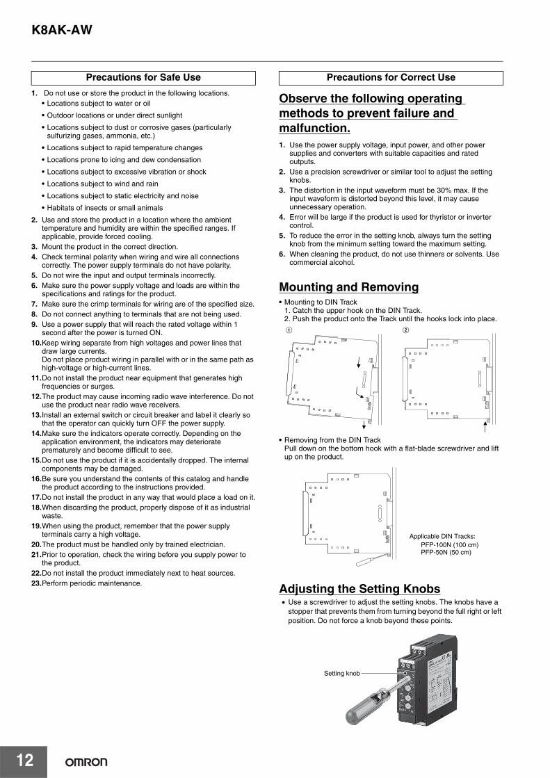
Mounting and Removing• Mounting to DIN Track
1. Catch the upper hook on the DIN Track.2. Push the product onto the Track until the hooks lock into place.
• Removing from the DIN TrackPull down on the bottom hook with a flat-blade screwdriver and lift up on the product.
Adjusting the Setting Knobs• Use a screwdriver to adjust the setting knobs. The knobs have a
stopper that prevents them from turning beyond the full right or left position. Do not force a knob beyond these points.
Precautions for Safe Use Precautions for Correct Use
A B
PFP-100N (100 cm)PFP-50N (50 cm)
Applicable DIN Tracks:
Setting knob

MEMO
13

MEMO
14
Terms and Conditions AgreementRead and understand this catalog.
Please read and understand this catalog before purchasing the products. Please consult your OMRON representative if you have any questions or comments.
Warranties.(a) Exclusive Warranty. Omron’s exclusive warranty is that the Products will be free from defects in materials and workmanship
for a period of twelve months from the date of sale by Omron (or such other period expressed in writing by Omron). Omron disclaims all other warranties, express or implied.
(b) Limitations. OMRON MAKES NO WARRANTY OR REPRESENTATION, EXPRESS OR IMPLIED, ABOUT NON-INFRINGEMENT, MERCHANTABILITY OR FITNESS FOR A PARTICULAR PURPOSE OF THE PRODUCTS. BUYER ACKNOWLEDGES THAT IT ALONE HAS DETERMINED THAT THE PRODUCTS WILL SUITABLY MEET THE REQUIREMENTS OF THEIR INTENDED USE.
Omron further disclaims all warranties and responsibility of any type for claims or expenses based on infringement by the Products or otherwise of any intellectual property right. (c) Buyer Remedy. Omron’s sole obligation hereunder shall be, at Omron’s election, to (i) replace (in the form originally shipped with Buyer responsible for labor charges for removal or replacement thereof) the non-complying Product, (ii) repair the non-complying Product, or (iii) repay or credit Buyer an amount equal to the purchase price of the non-complying Product; provided that in no event shall Omron be responsible for warranty, repair, indemnity or any other claims or expenses regarding the Products unless Omron’s analysis confirms that the Products were properly handled, stored, installed and maintained and not subject to contamination, abuse, misuse or inappropriate modification. Return of any Products by Buyer must be approved in writing by Omron before shipment. Omron Companies shall not be liable for the suitability or unsuitability or the results from the use of Products in combination with any electrical or electronic components, circuits, system assemblies or any other materials or substances or environments. Any advice, recommendations or information given orally or in writing, are not to be construed as an amendment or addition to the above warranty.
See http://www.omron.com/global/ or contact your Omron representative for published information.
Limitation on Liability; Etc.OMRON COMPANIES SHALL NOT BE LIABLE FOR SPECIAL, INDIRECT, INCIDENTAL, OR CONSEQUENTIAL DAMAGES, LOSS OF PROFITS OR PRODUCTION OR COMMERCIAL LOSS IN ANY WAY CONNECTED WITH THE PRODUCTS, WHETHER SUCH CLAIM IS BASED IN CONTRACT, WARRANTY, NEGLIGENCE OR STRICT LIABILITY.
Further, in no event shall liability of Omron Companies exceed the individual price of the Product on which liability is asserted.
Suitability of Use.Omron Companies shall not be responsible for conformity with any standards, codes or regulations which apply to the combination of the Product in the Buyer’s application or use of the Product. At Buyer’s request, Omron will provide applicable third party certification documents identifying ratings and limitations of use which apply to the Product. This information by itself is not sufficient for a complete determination of the suitability of the Product in combination with the end product, machine, system, or other application or use. Buyer shall be solely responsible for determining appropriateness of the particular Product with respect to Buyer’s application, product or system. Buyer shall take application responsibility in all cases.
NEVER USE THE PRODUCT FOR AN APPLICATION INVOLVING SERIOUS RISK TO LIFE OR PROPERTY OR IN LARGE QUANTITIES WITHOUT ENSURING THAT THE SYSTEM AS A WHOLE HAS BEEN DESIGNED TO ADDRESS THE RISKS, AND THAT THE OMRON PRODUCT(S) IS PROPERLY RATED AND INSTALLED FOR THE INTENDED USE WITHIN THE OVERALL EQUIPMENT OR SYSTEM.
Programmable Products.Omron Companies shall not be responsible for the user’s programming of a programmable Product, or any consequence thereof.
Performance Data.Data presented in Omron Company websites, catalogs and other materials is provided as a guide for the user in determining suitability and does not constitute a warranty. It may represent the result of Omron’s test conditions, and the user must correlate it to actual application requirements. Actual performance is subject to the Omron’s Warranty and Limitations of Liability.
Change in Specifications.Product specifications and accessories may be changed at any time based on improvements and other reasons. It is our practice to change part numbers when published ratings or features are changed, or when significant construction changes are made. However, some specifications of the Product may be changed without any notice. When in doubt, special part numbers may be assigned to fix or establish key specifications for your application. Please consult with your Omron’s representative at any time to confirm actual specifications of purchased Product.
Errors and Omissions.Information presented by Omron Companies has been checked and is believed to be accurate; however, no responsibility is assumed for clerical, typographical or proofreading errors or omissions.

0513
Authorized Distributor:
In the interest of product improvement, specifications are subject to change without notice.
Cat. No. N180-E1-01 0114 (0114)
© OMRON Corporation 2014 All Rights Reserved.
OMRON Corporation Industrial Automation Company
OMRON ELECTRONICS LLCOne Commerce Drive Schaumburg,IL 60173-5302 U.S.A.Tel: (1) 847-843-7900/Fax: (1) 847-843-7787
Regional HeadquartersOMRON EUROPE B.V.Wegalaan 67-69-2132 JD HoofddorpThe NetherlandsTel: (31)2356-81-300/Fax: (31)2356-81-388
Contact: www.ia.omron.comTokyo, JAPAN
OMRON ASIA PACIFIC PTE. LTD.No. 438A Alexandra Road # 05-05/08 (Lobby 2), Alexandra Technopark, Singapore 119967Tel: (65) 6835-3011/Fax: (65) 6835-2711
OMRON (CHINA) CO., LTD.Room 2211, Bank of China Tower, 200 Yin Cheng Zhong Road, PuDong New Area, Shanghai, 200120, ChinaTel: (86) 21-5037-2222/Fax: (86) 21-5037-2200