Embed Size (px)
Citation preview
Single Phase Energy meter based on STPM Metering IC and STM8L MCU
Nitin AgarwalMenka TangriIMS Systems LAB & Technical Marketing, India
Systems Lab & technical marketing
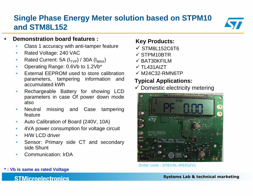
• Demonstration board features :• Class 1 accuracy with anti-tamper feature• Rated Voltage: 240 VAC• Rated Current: 5A (ITYP) / 30A (IMAX) • Operating Range: 0.6Vb to 1.2Vb*• External EEPROM used to store calibration
parameters, tampering information and accumulated kWh
• Rechargeable Battery for showing LCD parameters in case Of power down mode also
• Neutral missing and Case tampering feature
• Auto Calibration of Board (240V, 10A)• 4VA power consumption for voltage circuit• H/W LCD driver• Sensor: Primary side CT and secondary
side Shunt• Communication: IrDA
Key Products:� STM8L152C6T6� STPM10BTR� BAT30KFILM� TL431AIZT� M24C32-RMN6TP
* : Vb is same as rated Voltage
Single Phase Energy Meter solution based on STPM10 and STM8L152
Order code : STEVAL-IPE012V1
Typical Applications:� Domestic electricity metering
Systems Lab & technical marketing
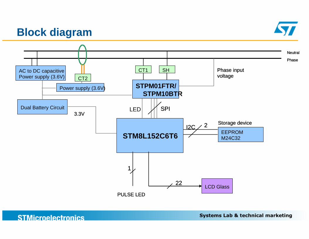
Block diagram
I2C
STM8L152C6T6
LCD Glass
EEPROM M24C32
Storage device
Neutral
Phase
SHAC to DC capacitivePower supply (3.6V)
22
2
CT1
PULSE LED
1
Phase inputvoltage
STPM01FTR/STPM10
SPIDual Battery Circuit3.3V
CT2
LED
Power supply (3.6V)
I2C
STM8L152C6T6
LCD Glass
EEPROM M24C32
Storage device
Neutral
Phase
SHAC to DC capacitivePower supply (3.6V)
22
2
CT1
PULSE LED
1
Phase inputvoltage
STPM01FTR/STPM10BTR
SPIDual Battery Circuit3.3V
CT2CT2
Power supply (3.6V)
Systems Lab & technical marketing
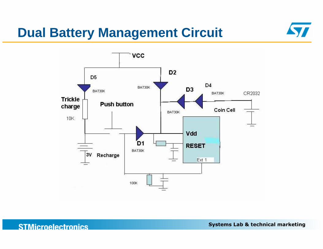
Dual Battery Management Circuit
Systems Lab & technical marketing
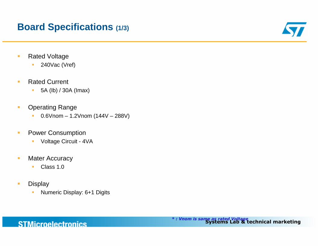
Board Specifications (1/3)
� Rated Voltage� 240Vac (Vref)
� Rated Current� 5A (Ib) / 30A (Imax)
� Operating Range� 0.6Vnom – 1.2Vnom (144V – 288V)
� Power Consumption� Voltage Circuit - 4VA
� Mater Accuracy� Class 1.0
� Display� Numeric Display: 6+1 Digits
* : Vnom is same as rated Voltage
Systems Lab & technical marketing
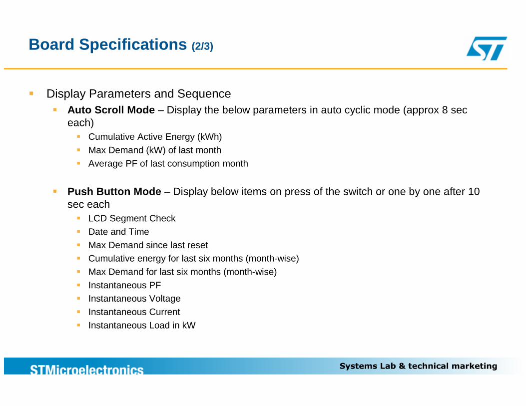
Board Specifications (2/3)
� Display Parameters and Sequence� Auto Scroll Mode – Display the below parameters in auto cyclic mode (approx 8 sec
each)� Cumulative Active Energy (kWh)� Max Demand (kW) of last month� Average PF of last consumption month
� Push Button Mode – Display below items on press of the switch or one by one after 10 sec each� LCD Segment Check� Date and Time� Max Demand since last reset� Cumulative energy for last six months (month-wise)� Max Demand for last six months (month-wise)� Instantaneous PF� Instantaneous Voltage� Instantaneous Current� Instantaneous Load in kW
Systems Lab & technical marketing
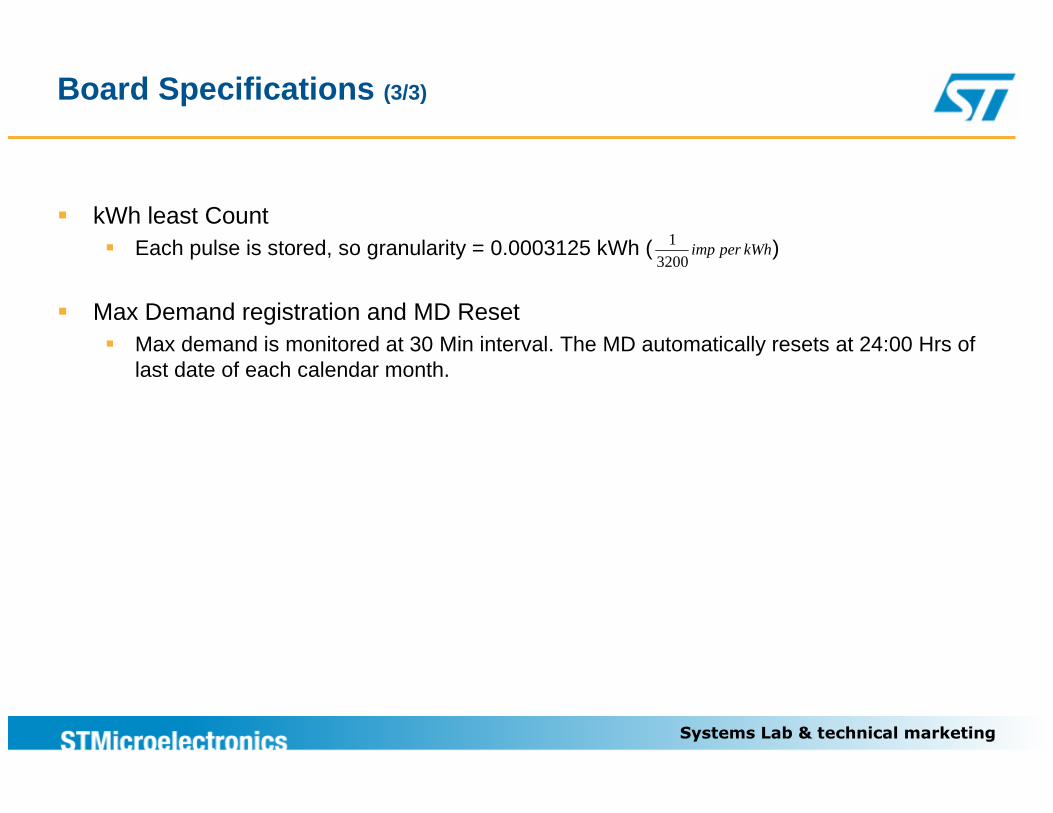
Board Specifications (3/3)
� kWh least Count� Each pulse is stored, so granularity = 0.0003125 kWh ( )
� Max Demand registration and MD Reset� Max demand is monitored at 30 Min interval. The MD automatically resets at 24:00 Hrs of
last date of each calendar month.
kWhperimp3200
1
Systems Lab & technical marketing
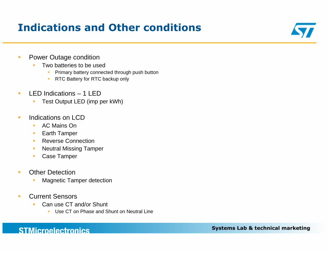
Indications and Other conditions
� Power Outage condition� Two batteries to be used
� Primary battery connected through push button� RTC Battery for RTC backup only
� LED Indications – 1 LED� Test Output LED (imp per kWh)
� Indications on LCD� AC Mains On� Earth Tamper� Reverse Connection� Neutral Missing Tamper� Case Tamper
� Other Detection� Magnetic Tamper detection
� Current Sensors� Can use CT and/or Shunt
� Use CT on Phase and Shunt on Neutral Line
Systems Lab & technical marketing
Tamper Protection Definitions
� Earth Tamper� Using Earth in place of neutral (load current is passed partially or fully through earth)
� Reverse Connection� Reversal of phase and neutral at mains
� Neutral Missing Tamper� When neutral is disconnected, the board will not be powered. During this condition (single wire
conditions), power supply is generated by a CT for powering up the board. The board detects this condition and starts recording energy when the load current is 2A or higher.
� Case Tamper� If attempt is made to open the meter body, the meter logs the date/time of meter opening tamper� The tamper information is displayed on LCD.
� Magnetic Tamper� When a magnet comes near to board, it pulls an IO low. This feature was requested by customer for
using in their customized LCD glass. This is not displayed in our LCD glass as we don’t have any segment free, but magnetic tamper feature is present in our solution.
Systems Lab & technical marketing
Communication Interface
� Optical Port / IrDA� Supported protocol IEC 62056-21 mode – C
� STM8L has inbuilt IrDA interface� IrDA can be disabled by a single bit only, so STM8L can work in SCI mode as well as IrDA mode
Systems Lab & technical marketing
� Board size = 9x7 CM2
� CT Specification� 2500T with x8 Multiplication factor in STPM01/STPM10� Connected to Primary Channel of STPM01//STPM10
� Shunt Specifications� 500 µΩ with x32 Multiplication factor in STPM01/STPM10� Connected to Secondary Channel of STPM01/STPM10
� Total IO usage� 22 LCD (LCD glass = 18x4)� 4 for STPM interface� 2 for I2C EEPROM interface � 3 for IRDA (including 1 IO for Shunt Down for IRDA module)� 1 Case tamper detection IO� 1 Magnetic tamper detection IO� 1 LED pin detection from STPM01/STPM10� 1 Pulse LED� 1 push button IO� 2 LSE� 1 - 50Hz output when neutral missing� 2 IOs are free
� 920 Bytes of EEPROM usage
Board Specs, EEPROM & IO Usage
Systems Lab & technical marketing
� Autoscroll timing = 8 Sec (Configurable)� Microcontroller CPU Frequency = 2MHz� Total Current Consumption < 7mA� Voltage Circuit Consumption < 4VA (@ Basic Voltage)� STPM read registers @25Hz� 920 Bytes of EEPROM usage� Approximately ~12% CPU loaded at no load
CPU Usage and Power Consumption
Systems Lab & technical marketing
EEPROM DATA structure
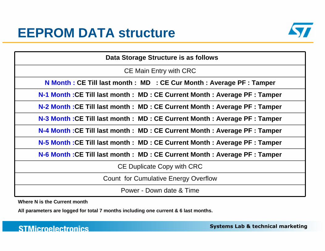
Data Storage Structure is as follows
CE Main Entry with CRC
N Month : CE Till last month : MD : CE Cur Month : Average PF : Tamper
N-1 Month : CE Till last month : MD : CE Current Month : Average PF : Tamper
N-2 Month : CE Till last month : MD : CE Current Month : Average PF : Tamper
N-3 Month : CE Till last month : MD : CE Current Month : Average PF : Tamper
N-4 Month : CE Till last month : MD : CE Current Month : Average PF : Tamper
N-5 Month : CE Till last month : MD : CE Current Month : Average PF : Tamper
N-6 Month : CE Till last month : MD : CE Current Month : Average PF : Tamper
CE Duplicate Copy with CRC
Count for Cumulative Energy Overflow
Power - Down date & Time
Where N is the Current month
All parameters are logged for total 7 months includ ing one current & 6 last months.
Systems Lab & technical marketing13
Log for seven months
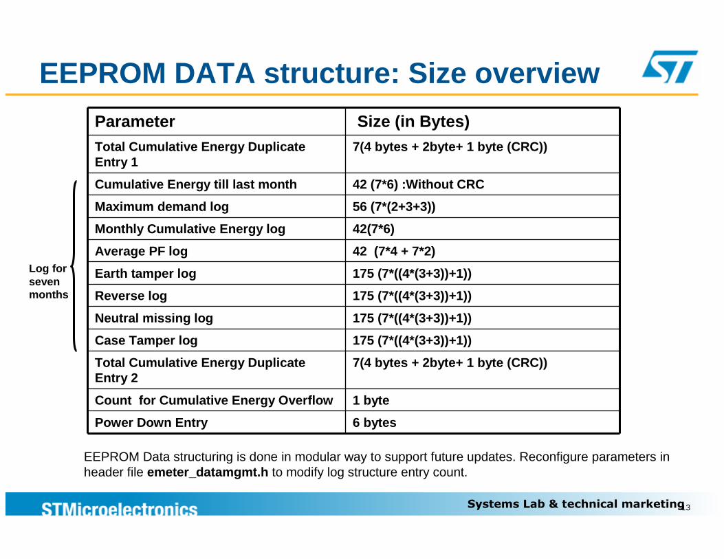
EEPROM Data structuring is done in modular way to support future updates. Reconfigure parameters in header file emeter_datamgmt.h to modify log structure entry count.
Parameter Size (in Bytes)Total Cumulative Energy Duplicate Entry 1
7(4 bytes + 2byte+ 1 byte (CRC))
Cumulative Energy till last month 42 (7*6) :Without CRC
Maximum demand log 56 (7*(2+3+3))
Monthly Cumulative Energy log 42(7*6)
Average PF log 42 (7*4 + 7*2)
Earth tamper log 175 (7*((4*(3+3))+1))
Reverse log 175 (7*((4*(3+3))+1))
Neutral missing log 175 (7*((4*(3+3))+1))
Case Tamper log 175 (7*((4*(3+3))+1))
Total Cumulative Energy Duplicate Entry 2
7(4 bytes + 2byte+ 1 byte (CRC))
Count for Cumulative Energy Overflow 1 byte
Power Down Entry 6 bytes
EEPROM DATA structure: Size overview
Systems Lab & technical marketing
STM8L152 LCD Driving
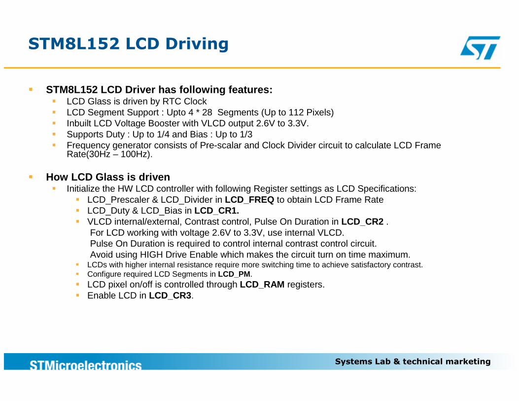
� STM8L152 LCD Driver has following features:� LCD Glass is driven by RTC Clock� LCD Segment Support : Upto 4 * 28 Segments (Up to 112 Pixels)� Inbuilt LCD Voltage Booster with VLCD output 2.6V to 3.3V. � Supports Duty : Up to 1/4 and Bias : Up to 1/3 � Frequency generator consists of Pre-scalar and Clock Divider circuit to calculate LCD Frame
Rate(30Hz – 100Hz).
� How LCD Glass is driven� Initialize the HW LCD controller with following Register settings as LCD Specifications:
� LCD_Prescaler & LCD_Divider in LCD_FREQ to obtain LCD Frame Rate� LCD_Duty & LCD_Bias in LCD_CR1.� VLCD internal/external, Contrast control, Pulse On Duration in LCD_CR2 .
For LCD working with voltage 2.6V to 3.3V, use internal VLCD.Pulse On Duration is required to control internal contrast control circuit. Avoid using HIGH Drive Enable which makes the circuit turn on time maximum.
� LCDs with higher internal resistance require more switching time to achieve satisfactory contrast.� Configure required LCD Segments in LCD_PM.� LCD pixel on/off is controlled through LCD_RAM registers.� Enable LCD in LCD_CR3.
Systems Lab & technical marketing
STM8L152 LCD Energy Meter Solution
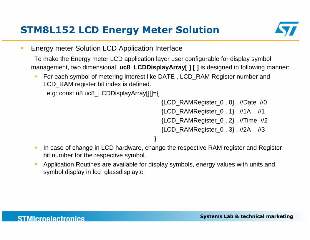
� Energy meter Solution LCD Application Interface
To make the Energy meter LCD application layer user configurable for display symbol management, two dimensional uc8_LCDDisplayArray[ ] [ ] is designed in following manner:
� For each symbol of metering interest like DATE , LCD_RAM Register number and LCD_RAM register bit index is defined.
e.g: const u8 uc8_LCDDisplayArray[][]={
{LCD_RAMRegister_0 , 0} , //Date //0
{LCD_RAMRegister_0 , 1} , //1A //1{LCD_RAMRegister_0 , 2} , //Time //2
{LCD_RAMRegister_0 , 3} , //2A //3
}
� In case of change in LCD hardware, change the respective RAM register and Register bit number for the respective symbol.
� Application Routines are available for display symbols, energy values with units and symbol display in lcd_glassdisplay.c.
Systems Lab & technical marketing
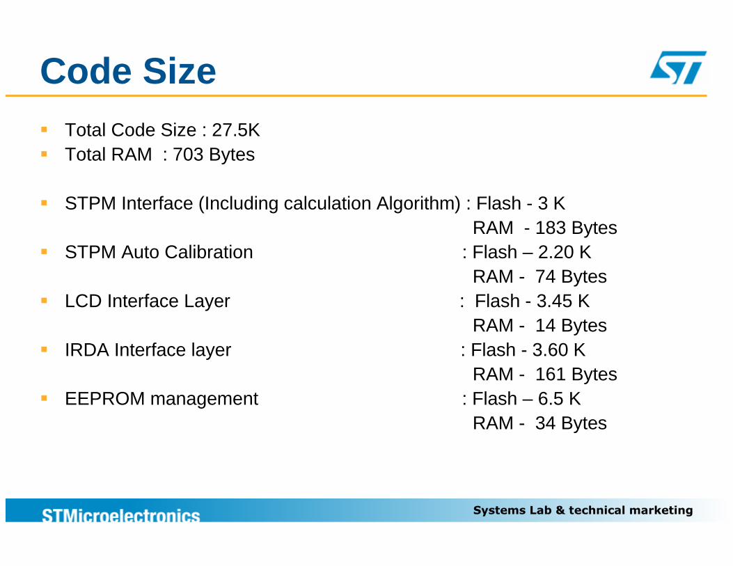
Code Size� Total Code Size : 27.5K� Total RAM : 703 Bytes
� STPM Interface (Including calculation Algorithm) : Flash - 3 K RAM - 183 Bytes
� STPM Auto Calibration : Flash – 2.20 K RAM - 74 Bytes
� LCD Interface Layer : Flash - 3.45 KRAM - 14 Bytes
� IRDA Interface layer : Flash - 3.60 K RAM - 161 Bytes
� EEPROM management : Flash – 6.5 K RAM - 34 Bytes
Systems Lab & technical marketing
STM8L (Key Features)
17
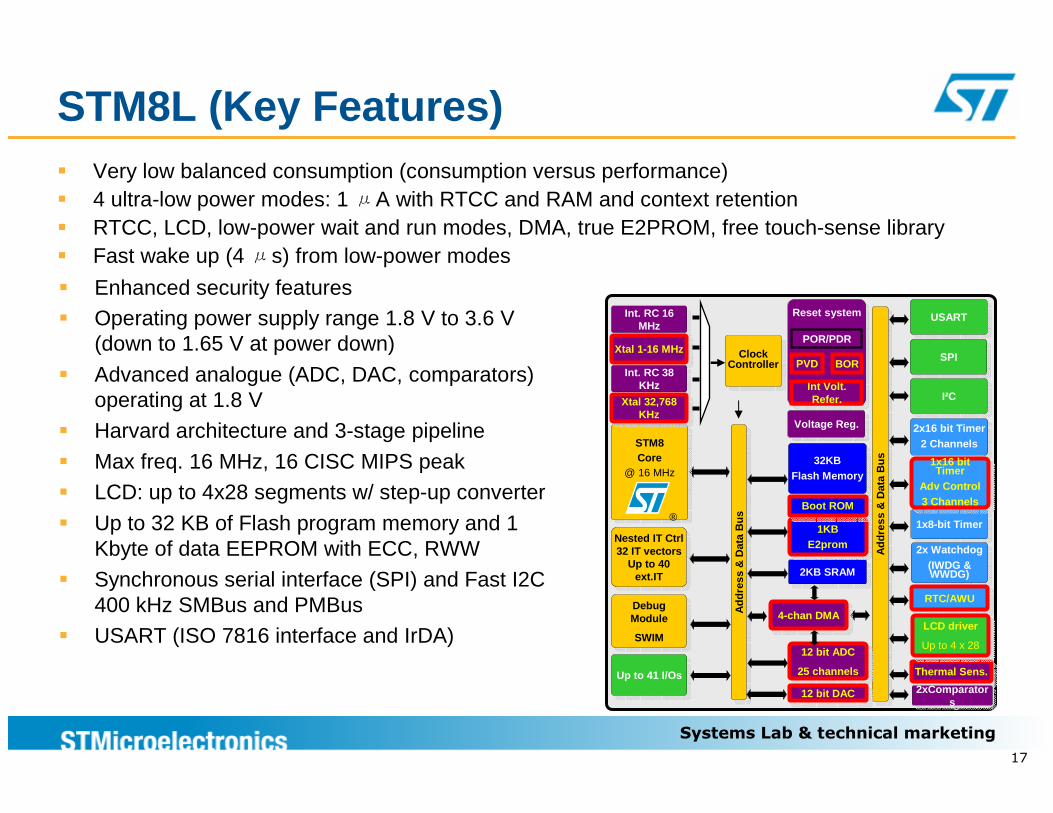
� Very low balanced consumption (consumption versus performance)� 4 ultra-low power modes: 1 μA with RTCC and RAM and context retention� RTCC, LCD, low-power wait and run modes, DMA, true E2PROM, free touch-sense library� Fast wake up (4 μs) from low-power modes
SPI SPI
USART USART
I²CI²C
2x16 bit Timer2 Channels
2x16 bit Timer2 Channels
1x8-bit Timer1x8-bit Timer
2x Watchdog(IWDG & WWDG)
2x Watchdog(IWDG & WWDG)
RTC/AWURTC/AWU
Add
ress
& D
ata
Bus
Add
ress
& D
ata
Bus
Thermal Sens.Thermal Sens.
2KB SRAM2KB SRAM
1KBE2prom
1KBE2prom
32KBFlash Memory
32KBFlash Memory
12 bit ADC
25 channels
12 bit ADC
25 channels
Reset systemReset system
Int Volt. Refer.
POR/PDR
Voltage Reg.Voltage Reg.
BOR
Add
ress
& D
ata
Bus
Add
ress
& D
ata
Bus
Nested IT Ctrl32 IT vectors
Up to 40 ext.IT
Nested IT Ctrl32 IT vectors
Up to 40 ext.IT
STM8Core
@ 16 MHz
STM8Core
@ 16 MHz
®
Int. RC 16 MHz
Int. RC 16 MHz
Xtal 1-16 MHzXtal 1-16 MHz
Int. RC 38 KHz
Int. RC 38 KHz
Clock Controller
Clock Controller
Debug Module
SWIM
Debug Module
SWIM
Up to 41 I/OsUp to 41 I/Os
PVD
Xtal 32,768 KHz
Xtal 32,768 KHz
4-chan DMA4-chan DMA
12 bit DAC12 bit DAC 2xComparators
2xComparators
Boot ROMBoot ROM
LCD driver
Up to 4 x 28
LCD driver
Up to 4 x 28
1x16 bit Timer
Adv Control3 Channels
1x16 bit Timer
Adv Control3 Channels
� Enhanced security features� Operating power supply range 1.8 V to 3.6 V
(down to 1.65 V at power down)
� Advanced analogue (ADC, DAC, comparators) operating at 1.8 V
� Harvard architecture and 3-stage pipeline
� Max freq. 16 MHz, 16 CISC MIPS peak� LCD: up to 4x28 segments w/ step-up converter
� Up to 32 KB of Flash program memory and 1 Kbyte of data EEPROM with ECC, RWW
� Synchronous serial interface (SPI) and Fast I2C 400 kHz SMBus and PMBus
� USART (ISO 7816 interface and IrDA)
Systems Lab & technical marketing
STPM
18
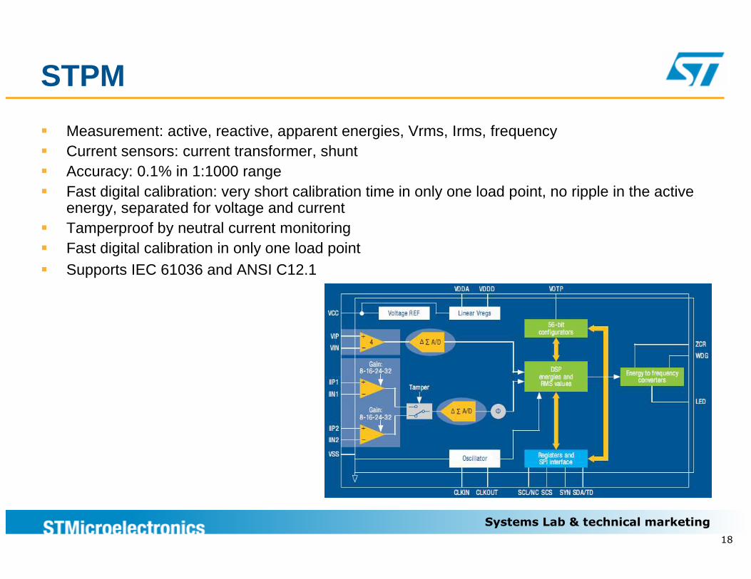
� Measurement: active, reactive, apparent energies, Vrms, Irms, frequency� Current sensors: current transformer, shunt� Accuracy: 0.1% in 1:1000 range� Fast digital calibration: very short calibration time in only one load point, no ripple in the active
energy, separated for voltage and current� Tamperproof by neutral current monitoring� Fast digital calibration in only one load point� Supports IEC 61036 and ANSI C12.1
Systems Lab & technical marketing
PC GUI
19
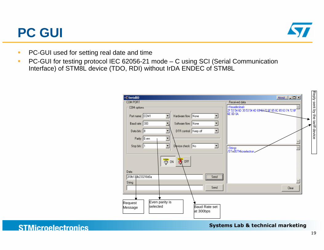
� PC-GUI used for setting real date and time� PC-GUI for testing protocol IEC 62056-21 mode – C using SCI (Serial Communication
Interface) of STM8L device (TDO, RDI) without IrDA ENDEC of STM8L
RequestMessage Baud Rate set
at 300bps
Reply sent by the tariff device
Even parity is selected
Systems Lab & technical marketing
Evaluation boards Availability
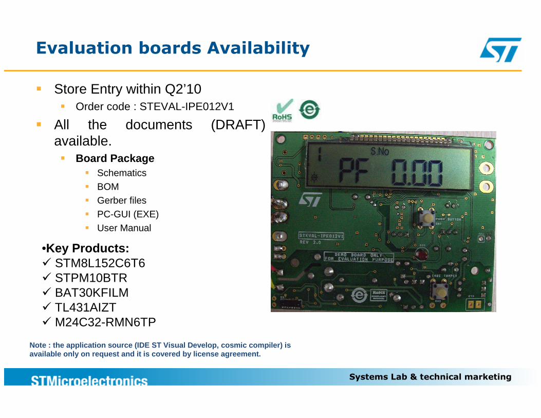
� Store Entry within Q2’10� Order code : STEVAL-IPE012V1
� All the documents (DRAFT) available.� Board Package
� Schematics� BOM� Gerber files� PC-GUI (EXE)� User Manual
•Key Products:� STM8L152C6T6� STPM10BTR� BAT30KFILM� TL431AIZT� M24C32-RMN6TP
Note : the application source (IDE ST Visual Develo p, cosmic compiler) is available only on request and it is covered by lice nse agreement.