Embed Size (px)
Citation preview

General rights Copyright and moral rights for the publications made accessible in the public portal are retained by the authors and/or other copyright owners and it is a condition of accessing publications that users recognise and abide by the legal requirements associated with these rights.
• Users may download and print one copy of any publication from the public portal for the purpose of private study or research. • You may not further distribute the material or use it for any profit-making activity or commercial gain • You may freely distribute the URL identifying the publication in the public portal
If you believe that this document breaches copyright please contact us providing details, and we will remove access to the work immediately and investigate your claim.
Downloaded from orbit.dtu.dk on: May 08, 2018
Single-mode ytterbium-doped large-mode-area photonic bandgap rod fiber amplifier
Alkeskjold, Thomas Tanggaard; Scolari, Lara; Broeng, Jes; Laurila, Marko
Published in:Optics Express
Link to article, DOI:10.1364/OE.19.007398
Publication date:2011
Document VersionPublisher's PDF, also known as Version of record
Link back to DTU Orbit
Citation (APA):Alkeskjold, T. T., Scolari, L., Broeng, J., & Laurila, M. (2011). Single-mode ytterbium-doped large-mode-areaphotonic bandgap rod fiber amplifier. Optics Express, 19(8), 7398-7409. DOI: 10.1364/OE.19.007398

Single-mode ytterbium-doped large-mode-area photonic bandgap rod fiber amplifier
Thomas Tanggaard Alkeskjold,1,*
Marko Laurila,2 Lara Scolari,
1 and Jes Broeng
1
1NKT Photonics, Blokken 84, 3460 Birkerød, Denmark 2DTU Fotonik, Department of Photonics Engineering, Technical University of Denmark, 2800 Kgs. Lyngby, Denmark
Abstract: Enabling Single-Mode (SM) operation in Large-Mode-Area (LMA) fiber amplifiers and lasers is critical, since a SM output ensures high beam quality and excellent pointing stability. In this paper, we demonstrate and test a new design approach for achieving SM LMA rod fibers by using a photonic bandgap structure. The structure allows resonant coupling of higher-order modes from the core and acts as a spatially Distributed Mode Filter (DMF). With this approach, we demonstrate passive SM performance in an only ~50cm long and straight ytterbium-doped rod fiber. The amplifier has a mode field diameter of ~59µm at 1064nm and exhibits a pump absorption of 27dB/m at 976nm.
©2011 Optical Society of America
OCIS codes: (060.2310) Fiber optics; (060.4005) Microstructured fibers; (060.3510) Lasers, fiber.
References and links
1. C. D. Brooks and F. Di Teodoro, “Multi-megawatt peak-power, single-transverse-mode operation of a 100 µm core diameter, Yb-doped rod-like photonic crystal fiber amplifier,” Appl. Phys. Lett. 89(11), 111119 (2006).
2. J. Limpert, O. Schmidt, J. Rothhardt, F. Röser, T. Schreiber, A. Tünnermann, S. Ermeneux, P. Yvernault, and F. Salin, “Extended single-mode photonic crystal fiber lasers,” Opt. Express 14(7), 2715–2720 (2006).
3. J. P. Koplow, D. A. V. Kliner, and L. Goldberg, “Single-mode operation of a coiled multimode fiber amplifier,” Opt. Lett. 25(7), 442–444 (2000).
4. C. Liu, G. Chang, N. Litchinister, D. Guertin, N. Jacobson, K. Tankala, and A. Galvanauskas, “Chirally coupled core fibers at 1550-nm and 1064-nm for effectively single-mode core size scaling,” in Conference on Lasers and Electro-Optics/Quantum Electronics and Laser Science Conference and Photonic Applications Systems Technologies, OSA Technical Digest Series (CD) (Optical Society of America, 2007), paper CTuBB3.
5. L. Dong, H. A. McKay, L. Fu, M. Ohta, A. Marcinkevicius, S. Suzuki, and M. E. Fermann, “Ytterbium-doped all glass leakage channel fibers with highly fluorine-doped silica pump cladding,” Opt. Express 17(11), 8962–8969 (2009).
6. M. E. Fermann, “Single-mode excitation of multimode fibers with ultrashort pulses,” Opt. Lett. 23(1), 52–54 (1998).
7. J. W. Nicholson, J. M. Fini, A. M. DeSantolo, E. Monberg, F. DiMarcello, J. Fleming, C. Headley, D. J. DiGiovanni, S. Ghalmi, and S. Ramachandran, “A higher-order-mode erbium-doped-fiber amplifier,” Opt. Express 18(17), 17651–17657 (2010).
8. F. Jansen, F. Stutzki, H.-J. Otto, M. Baumgartl, C. Jauregui, J. Limpert, and A. Tünnermann, “The influence of index-depressions in core-pumped Yb-doped large pitch fibers,” Opt. Express 18(26), 26834–26842 (2010).
9. N. Mortensen and J. Folkenberg, “Near-field to far-field transition of photonic crystal fibers: symmetries and interference phenomena,” Opt. Express 10(11), 475–481 (2002).
1. Introduction
The rapid development and deployment of high-peak power and high pulse energy fiber amplifier systems have been fuelled by the development of large-mode-area (LMA) fiber amplifiers, having larger and larger effective mode area. The continuous demand for larger effective area is driven by the need to mitigate nonlinear effects such as Four-Wave Mixing (FWM), Self-Phase Modulation (SPM), and Stimulated Raman Scattering (SRS), which can seriously distort pulse amplification due to spectral and/or temporal broadening. Larger effective area is also needed in order to increase the damage threshold at the fiber facets, which ultimately sets the limit of the maximum possible extractable pulse energy. In most cases, pure silica endcaps can be fused to the fiber facet, thereby enabling higher pulse
#143487 - $15.00 USD Received 1 Mar 2011; revised 21 Mar 2011; accepted 27 Mar 2011; published 1 Apr 2011(C) 2011 OSA 11 April 2011 / Vol. 19, No. 8 / OPTICS EXPRESS 7398

energies. Equally important is the need for having high beam quality and excellent pointing stability. This is required for successfully applying fiber amplifiers in for example semiconductor and solar cell scribing applications or for stable and efficient frequency conversion of NIR pulses. As the core diameter of LMA fibers is increased to beyond approx. 15µm, single-mode fibers, based on a conventional step-index design, becomes difficult to manufacture with sufficient yield due to the required index precision obtainable even with
state-of-the-art rare-earth-doped core manufacturing processes (+/1e-4). For the fabrication of larger SM cores other strategies must be applied. For example, manufacturing of low-NA SM LMA Photonic Crystal Fibers (PCFs), using an air/silica microstructured cladding, has typically higher yield than the step-index approach and have successfully been applied in amplifier systems [1,2]. Another approach is to use Multi-Mode (MM) step-index fiber cores, where the Higher-Order-Modes (HOMs) are either suppressed by utilizing differential bend loss [3], chirally coupled cores [4] or differential mode loss in so-called leaky-channel fibers [5]. SM operation in highly MM fibers can also be obtained by matching the launched beam to the FM and carefully exciting the Fundamental Mode (FM) only [6]. Finally, it is possible to excite and amplify only one specific HOM, which typically has large effective area, by using long-period gratings as mode converters at the input and output to achieve FM operation and good beam quality [7].
In this paper, we demonstrate and test a new design approach, which utilizes high-index ring-shaped DMFs. A low-NA SM ytterbium-doped fiber rod amplifier with 59µm mode field diameter is realized.
2. Fiber design
An important manufacturing advantage of air/silica PCF structures is the ability to modify the effective cladding index during the fiber draw. This is accomplished by inflating or deflating the air holes of the cladding. This unique possibility offered by PCFs allows for compensating batch to batch refractive index variations of the core material and, in this way, maintaining a uniform core NA from batch to batch. The air holes also allows the core NA to be fine-tuned with high precision and low-NA fibers can, in this way, be manufactured with acceptable yield and cost. One important aspect of a LMA PCF design is its ability to be able to compensate the total expected batch to batch variations as effectively as possible. To evaluate this aspect, we have carried out finite element simulations (JCMwave, GmbH Germany) on a 85µm core PCF rod amplifier having a hexagonal LMA structure. The core is defined by omitting 19 capillary tubes in the center of the fiber and replacing them with solid ytterbium rods. The pitch (Λ) is 14.5µm. Figure 1 shows the effective modal index of the LP11 mode of the rod (Fig. 1, inset) as function of the relative hole diameter (d/Λ) for four different core doping levels – from a slightly up-doped core having + 1e-4 refractive index to a slightly
down-doped core having 2e-4 refractive index, all relative to silica. This variation in doping
level is slightly higher than what can be expected from the manufacturing process (+/1e-4), but the variation in modal LP11 index is a good representative of the effective index variation that a cladding structure should be able to reach by modifying the hole size of the cladding structure.
#143487 - $15.00 USD Received 1 Mar 2011; revised 21 Mar 2011; accepted 27 Mar 2011; published 1 Apr 2011(C) 2011 OSA 11 April 2011 / Vol. 19, No. 8 / OPTICS EXPRESS 7399

Fig. 1. Effective mode index of the LP11 HOM mode of a 85µm core hexagonal rod amplifier as function of relative hole diameter (d/Λ) and doping level of the core elements.
A cladding structure should be able to be adjusted such that the NA of the core ensures SM operation without introducing high confinement loss to the FM. Taking typical core batch
to batch variations into account (+/1e-4), this means that the upper cladding state (often the Fundamental Space-filling Mode (FSM)) should be able to cross all four LP11 lines of Fig. 1, by adjusting the hole size only. The mode-spacing between the FM and HOM is in this case ~5e-5, and the accuracy of the effective cladding index should, therefore, be manufactured to
within approx. +/1e-5, which is difficult but feasible. Figure 2 shows the FSM as function of d/Λ of two cladding structures: 1) a hexagonal
cladding structure (Fig. 1, inset) and 2) a honeycomb-type cladding structure (Fig. 2, inset).
#143487 - $15.00 USD Received 1 Mar 2011; revised 21 Mar 2011; accepted 27 Mar 2011; published 1 Apr 2011(C) 2011 OSA 11 April 2011 / Vol. 19, No. 8 / OPTICS EXPRESS 7400

Fig. 2. Modal LP11 indices, as in Fig. 1, and FSM for the hexagonal cladding (FSMhex) and for a honeycomb-type cladding structure having pure silica elements (FSMhoney0) and + 3e-4 updoped elements(FSMhoney3).
The figure shows that it is difficult to achieve sufficient low NA with a conventional
hexagonal air/silica structure unless the core is down-doped to about 2e-4 to 3e-4 below silica or air holes are very small (d/Λ<0.05). Down-doping is feasible reduces the mode-spacing between the FM and HOM because the HOM has more field outside the down-doped core than the FM. This can make manufacturing yield low due to an increase in required index precision. Furthermore, down-doping should be used with some care since it can, in some cases, degrade beam quality through a shaping of the FM [8]. Ideally, the core index should be equal to silica or slightly above silica, but this sets some very difficult requirements to this cladding type. One way to increase the cladding index, and achieve low NA for silica matched cores, is to use a honeycomb-type cladding structure as shown in the inset of Fig. 2. The honeycomb „core‟ can either be pure silica or slightly up-doped. Figure 2 shows the FSM of the honeycomb-type cladding structure for both a pure silica (FSMhoney0) and a + 3e-4 up-doped (FSMhoney3) honeycomb structure. The up-doped honeycomb-type cladding structure is better at enabling low NA operation for silica matched and slightly up-doped cores, but cannot be used to compensate for all the LP11 modal index variations that can be expected from batch to batch index variations.
A more manufacturing „friendly‟ cladding structure should, therefore, support cladding states having an upper effective mode index that is equal to silica for small holes (d/Λ~0.1), such that a HOM is not guided for a slightly up-doped core ( + 1e-4). For a larger hole size (d/Λ~0.3), the effective cladding mode index should be somewhat lower than silica to ensure
that the FM is guided in a slightly down-doped core (2e-4) and that any HOM is not guided. The highest index cladding state should, therefore, cross all four LP11 lines of Fig. 1 in the interval 0.1<d/Λ<0.3.
One way of achieving this, is to use multiple spatially localized elements in the cladding, which exhibit waveguiding properties that are strongly affected by a change in the size of an air hole. Figure 3 shows an example of such a structure, which is a ring-shaped high-index
#143487 - $15.00 USD Received 1 Mar 2011; revised 21 Mar 2011; accepted 27 Mar 2011; published 1 Apr 2011(C) 2011 OSA 11 April 2011 / Vol. 19, No. 8 / OPTICS EXPRESS 7401

germanium element. The element contains a center element with index n1 (this case an air hole with n1 = 1), a high-index ring (this case germanium doped silica) with index n2 and an outer ring (this case pure silica) with index n3. As the air hole is inflated or deflated, the thickness of the ring changes and thereby affects the effective index of the (super) modes that this structure supports.
Fig. 3. Schematic and microscope image of a DMF element having a central air hole surrounded by a high-index germanium ring with index n2 and an outer silica shell with index n3.
This type of element can be arranged for example in a hexagonal lattice as shown in Fig. 4a, in a honeycomb-type lattice as shown in Fig. 4b, or in a different pattern than shown here. In these cases, the individually elements are optically coupled elements and they form cladding states that ensures that HOMs are not guided in the core. This is achieved by adjusting the air holes of the cladding structure such that the core NA becomes sufficiently small to only support a single-mode. The elements thereby form a Distributed Mode Filter (DMF).
Fig. 4. Schematic of rod fiber design with DMF elements arranged in a hexagonal lattice (a) and in a honeycomb-type lattice (b).
An important manufacturing parameter for the DMF structure is how sensitive the effective cladding index is to a change in hole size. This can be expressed as a dn/dD [1/] value (where n represents the effective index and D the hole diameter), which should be negative and not excessive large but not excessive small either. If dn/dD is too large, it will become difficult to adjust the hole size with sufficient precision and if too small, large hole
#143487 - $15.00 USD Received 1 Mar 2011; revised 21 Mar 2011; accepted 27 Mar 2011; published 1 Apr 2011(C) 2011 OSA 11 April 2011 / Vol. 19, No. 8 / OPTICS EXPRESS 7402

size variation is needed and it will be difficult to maintain the specified dimensions of the final rod fiber.
Figure 5 shows the FSM of the DMF element either arranged in a hexagonal lattice (Fig.
4a) and in a honeycomb-type lattice (Fig. 4b), having dn/dD values of 3.8e-3 and 2.4e-3, respectively. It can be observed that both structures supports cladding modes that crosses all four LP11 lines and that the honeycomb-type lattice has the lowest slope and is, therefore, more feasible for achieving SM performance.
Fig. 5. Modal LP11 indices as in Fig. 1a and the FSM of the DMF elements arranged in a hexagonal (FSMDMF-HEX) and in a honeycomb-type lattice (FSMDMF-HONEY).
Figure 6 shows a full modal finite element simulation of the fiber illustrated in Fig. 4b. The index of the germanium rings (n2) is + 25e-4 relative to silica. The size of the germanium ring is chosen such that the V parameter of the DMF element is V~2 when the air hole is totally collapsed (see later). The ring thickness decreases from about 4µm to 2.8µm when the air hole is inflated from d/Λ~0.1 to d/Λ~0.3. The figure shows the modal index of the FM and the first HOM/cladding mode as d/Λ is adjusted from 0.15 to 0.25 and germanium mass conservation is taken into account. For d/Λ > 0.195 the fiber is MM but for 0.175<d/Λ<0.195 the fiber only supports a single FM as the cladding modes reduces the NA such that only the FM is guided. For d/Λ<0.175, the FM couples to the DMF element and the fiber does not guide light in the core. This non-guiding regime is very useful, because it will show up as a notch in the transmission spectrum of the core light and can directly be used for identifying the lower wavelength of the SM region of the fiber.
Figure 7 shows the modal field evolution of the FM and HOM of the rod fiber as the hole diameter is decreased from d/Λ = 0.2 to d/Λ = 0.175 and illustrates how the DMF cladding states crosses the HOM index around d/Λ~0.2 and reduces the core NA and ensures SM operation of the rod.
#143487 - $15.00 USD Received 1 Mar 2011; revised 21 Mar 2011; accepted 27 Mar 2011; published 1 Apr 2011(C) 2011 OSA 11 April 2011 / Vol. 19, No. 8 / OPTICS EXPRESS 7403
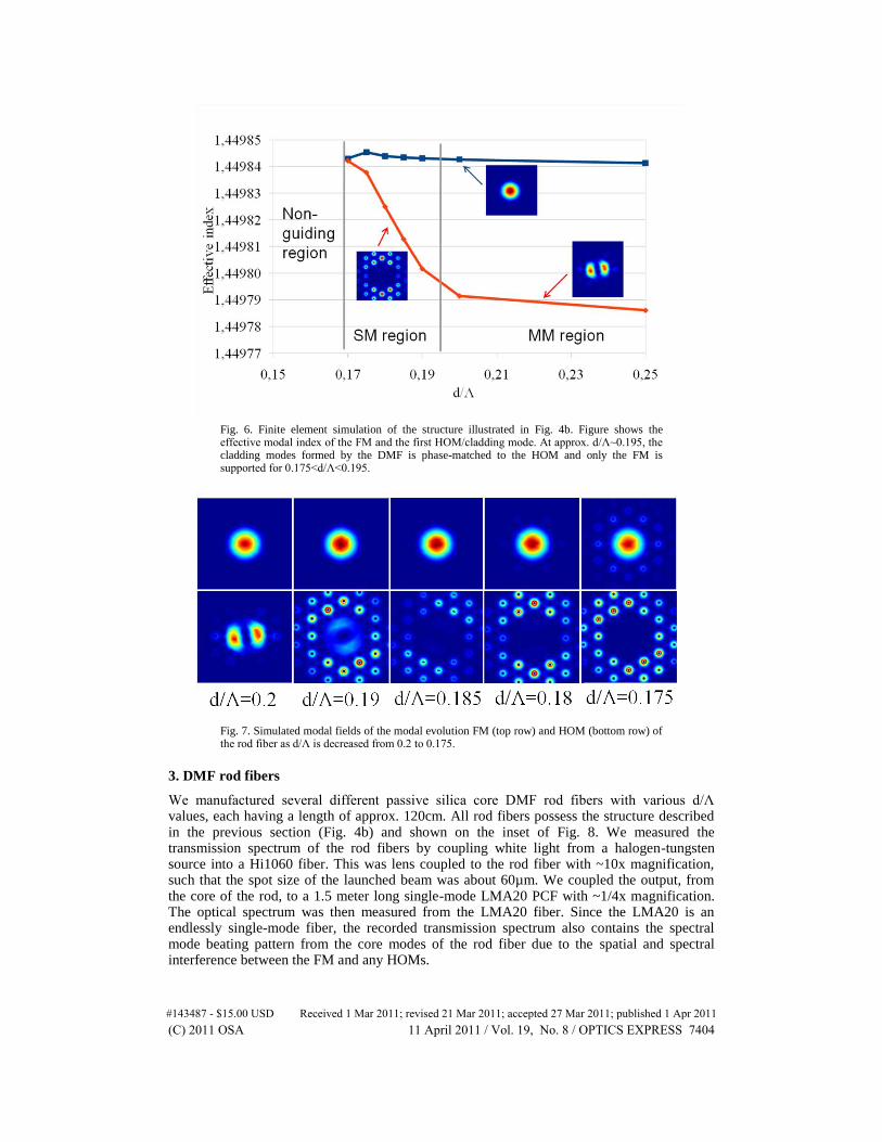
Fig. 6. Finite element simulation of the structure illustrated in Fig. 4b. Figure shows the effective modal index of the FM and the first HOM/cladding mode. At approx. d/Λ~0.195, the cladding modes formed by the DMF is phase-matched to the HOM and only the FM is supported for 0.175<d/Λ<0.195.
Fig. 7. Simulated modal fields of the modal evolution FM (top row) and HOM (bottom row) of the rod fiber as d/Λ is decreased from 0.2 to 0.175.
3. DMF rod fibers
We manufactured several different passive silica core DMF rod fibers with various d/Λ values, each having a length of approx. 120cm. All rod fibers possess the structure described in the previous section (Fig. 4b) and shown on the inset of Fig. 8. We measured the transmission spectrum of the rod fibers by coupling white light from a halogen-tungsten source into a Hi1060 fiber. This was lens coupled to the rod fiber with ~10x magnification, such that the spot size of the launched beam was about 60µm. We coupled the output, from the core of the rod, to a 1.5 meter long single-mode LMA20 PCF with ~1/4x magnification. The optical spectrum was then measured from the LMA20 fiber. Since the LMA20 is an endlessly single-mode fiber, the recorded transmission spectrum also contains the spectral mode beating pattern from the core modes of the rod fiber due to the spatial and spectral interference between the FM and any HOMs.
#143487 - $15.00 USD Received 1 Mar 2011; revised 21 Mar 2011; accepted 27 Mar 2011; published 1 Apr 2011(C) 2011 OSA 11 April 2011 / Vol. 19, No. 8 / OPTICS EXPRESS 7404

Figure 8 shows an example of such a transmission spectrum. As expected, the fiber contains a transmission notch around 1µm, corresponding to the modal crossing of the FM with the modes of the DMF elements. The spectrum does not contain any oscillations from 1050nm-1070nm, which indicate that only one mode is supported and that the fiber is SM in this region. Towards longer wavelengths a new region appears (MM1), where the spectrum contains a harmonic originating from the beating between the FM mode and the first HOM. In the MM2 region, at about 1150nm-1300nm, several harmonics enters the beating spectrum caused by a second set of HOMs which becomes guided and interferes with the FM and the first HOM. In a step-index analogy, the SM region could be compared to the V<2.4 case, MM1 region to the 2.4<V<3.8 case and the MM2 region to the V>3.8 case. Figure 9 shows the measured upper and lower limit of the SM region of the manufactured DMF rod fibers. The SM region is plotted as function of the relative air hole diameter of the hole in the DMF element. The figure shows that the SM region can be positioned from ~1064nm to ~910nm by adjusting the hole size of the cladding structure. Inset of Fig. 9 shows the near field at 1064nm. The mode field diameter (1/e
2 of intensity) was measured to 59µm. Figure 10 shows
a series of near field images at 1064nm wavelength. The input beam is translated along x and y direction with the purpose of exciting any HOMs. No HOMs could be observed by translating both a 60µm and 30µm spot size input beam in the x and y direction across the core.
The transmission notch could furthermore be utilized for suppression of Amplified Spontaneous Emission (ASE), for example for 1030nm ASE suppression in a 1064nm low rep-rate amplifier or gain-shaping for operating at longer wavelengths.
We also manufactured a 100µm core rod fiber by up-scaling the 85µm core by 117%. The SM region scales almost linearly with the thickness of the germanium rings, and we therefore expected the 100µm core rod to be SM at approx. 1240nm. The rod fiber was measured to be SM at 1224nm wavelength i.e. at slightly lower wavelength than expected. The near field at 1224nm is shown on Fig. 11. The rod exhibited a mode field diameter of ~72µm, which was measured using an InGaAs camera (Spiricon XEVA XC-130) and a super-continuum source (SuperK Extreme, NKT Photonics) combined with a dual acousto-optic filter for NIR and visible wavelength selection (SpectraK Dual, NKT Photonics), which generated an 8nm wide signal centered at 1224nm.
#143487 - $15.00 USD Received 1 Mar 2011; revised 21 Mar 2011; accepted 27 Mar 2011; published 1 Apr 2011(C) 2011 OSA 11 April 2011 / Vol. 19, No. 8 / OPTICS EXPRESS 7405

Fig. 8. Mode beating spectrum of a passive 85µm core DMF rod fiber. Inset shows a microscope image of the rod fiber.
Fig. 9. Measured SM region of the 85µm core DMF rod fiber shown in the inset of Fig. 8 as function of the relative hole diameter of the hole in the DMF element.
#143487 - $15.00 USD Received 1 Mar 2011; revised 21 Mar 2011; accepted 27 Mar 2011; published 1 Apr 2011(C) 2011 OSA 11 April 2011 / Vol. 19, No. 8 / OPTICS EXPRESS 7406

Fig. 10. Near field images of the passive DMF rod fiber at 1064nm wavelength. Images show the near field as the input beam is translated along x (top row) and y (bottom row) direction.
Fig. 11. Near field image of a passive 100µm core DMF rod at 1224nm wavelength. The mode field diameter was measured to 72.5µm at 1224nm.
We designed and manufactured an ytterbium-doped version of the DMF rod fiber described earlier. We used silica indexed-matched ytterbium as the core material. The rod fiber contained a MM pump air-clad with 267µm diameter, had 1.7mm outer diameter and a length of 120cm. We measured the pump absorption to be ~27dB/m (nominal) at 976nm using the cutback technique. A small fraction of the pump is coupled directly to the DMF elements and does not get absorbed, but is guided along the length of the rod. The total area of the DMF elements is about 2-3% of the total area of the pump cladding, but the NA of the DMF elements is only 0.085. If the rod is pumped with a standard 200µm 0.22NA MM pump, the pump light coupled to the DMF elements will only be about 0.7%. In case of a 267µm 0.6NA pump beam, it will only be 0.05% of the total pump.
The manufactured ytterbium-doped rod fiber was SM at 1064nm and the near field stability was evaluated at 1064nm by translating the input beam in both x and y direction. Figure 12 shows a series of near field images and shows that no HOMs could be excited even with a misaligned input beam. We performed cutback measurements on the 120cm rod and evaluated the modal stability on the rod having a length of 120cm, 89cm, 68cm, 53cm and 40cm. Only the FM could be excited in the 120cm, 89cm, 68cm and 53cm long rod. In the 40cm long rod, an asymmetric mode could be excited when the launched beam was misaligned in the transversal direction. This asymmetric near field is shown on Fig. 13a and is a sign of weak LP11 content. With a normal symmetric launch beam, the near field showed only signs of the FM and no HOM content (Fig. 13b).
#143487 - $15.00 USD Received 1 Mar 2011; revised 21 Mar 2011; accepted 27 Mar 2011; published 1 Apr 2011(C) 2011 OSA 11 April 2011 / Vol. 19, No. 8 / OPTICS EXPRESS 7407

Fig. 12. Near field images of the ytterbium-doped DMF rod fiber at 1064nm wavelength. Images show the near field as the input beam is translated along x (top row) and y (bottom row) direction.
Fig. 13. Near field images of the 40cm long rod when the input beam is misaligned along the transversal direction and a slightly asymmetric mode is excited (a) and with optimum aligned input beam the FM is excited (b).
In high peak power and high pulse energy rod fiber systems, it is preferred that the surface of the output end facet is of high quality to facilitate high damage threshold. This can be accomplished by fusing high-purity fused silica AR-coated end caps to the end facet or in some cases it is sufficient to polish the rod facet in either 0° angle, for achieving cavity feedback in Q-switched systems, or with an angle of few degrees to avoid feedback in amplifier configurations. In all cases, it is crucial that the last few hundreds of micrometers of the rod are collapsed such that the facet can be polished or end caps can be fused onto. In this DMF design, the DMF element is designed to have V~2 when the air holes are collapsed. For V~2 the DMF element is a SM waveguide and only supports one spatial mode having an effective modal index higher than silica. As the mode has higher effective index than silica, it cannot couple to the FM of the rod fiber since this has an effective mode index lower than silica. The FM of the rod can, therefore, propagate freely without coupling to the DMF elements in the collapsed zone of the rod. Figure 14a shows the near field of the rod when the end facet is collapsed for about 60µm. The mode is undisturbed by the collapsed DMF elements. Equally important is the far field, which can indicate if more modes are excited in the collapsed zone. Figures 14b and 14c show the field when the focus of the lens is moved away from the facet and towards the far field. The near field transforms from a Gaussian-like mode to a hexagon-shaped far field, which rotates π/6 from an intermediate distance to the far field [9]. In [9], six far field side-lopes was predicted and observed in the far field but these lopes cannot be observed here. These lopes were predicted to be two-orders of magnitude lower in intensity and might not be visible in our experiment due to the presence of cladding light guided by the pump cladding.
#143487 - $15.00 USD Received 1 Mar 2011; revised 21 Mar 2011; accepted 27 Mar 2011; published 1 Apr 2011(C) 2011 OSA 11 April 2011 / Vol. 19, No. 8 / OPTICS EXPRESS 7408

Fig. 14. Near field of the 120cm rod with a collapsed output zone of ~60µm (a), near field to far field transition of the field (b), far field of the FM (c).
4. Conclusion
We have successfully tested and demonstrated a new photonic bandgap design for achieving SM performance in an ytterbium-doped LMA rod fiber. We have manufactured both passive and active rods based on a distributed mode filter design and both types showed SM performance. The ytterbium-doped rod exhibited SM performance in lengths longer than ~50cm. The rod fibers had a mode field diameter of 59µm at 1064nm wavelength. The ytterbium-doped rod was manufactured with a MM pump cladding and the pump absorption was measured to ~27dB/m at 976nm, thereby enabling effective device lengths of about 60-70cm.
Acknowledgment
The project is supported with funding from the European Union (EU) FP7 project LIFT (CP- IP 228587-1- LIFT).
#143487 - $15.00 USD Received 1 Mar 2011; revised 21 Mar 2011; accepted 27 Mar 2011; published 1 Apr 2011(C) 2011 OSA 11 April 2011 / Vol. 19, No. 8 / OPTICS EXPRESS 7409


![Ultralow-threshold ytterbium-doped glass laser fabricated ... · The author modi ed a microtoroid laser model, developed for erbium silica microlasers by Min [21], for the ytterbium](https://img.pdfslide.us/doc/110x75/5f30f8e96723ab4524020792/ultralow-threshold-ytterbium-doped-glass-laser-fabricated-the-author-modi-ed.jpg)


![4-Lesson4-Intrinsic & Doped Semiconductor [Compatibility Mode]](https://img.pdfslide.us/doc/110x75/577d35001a28ab3a6b8f57a4/4-lesson4-intrinsic-doped-semiconductor-compatibility-mode.jpg)