Embed Size (px)
Citation preview
1A-1
1A
(800) 624-8511www.phdinc.com/crs
SOLUTIONS FORINDUSTRIAL AUTOMATION CAT-03
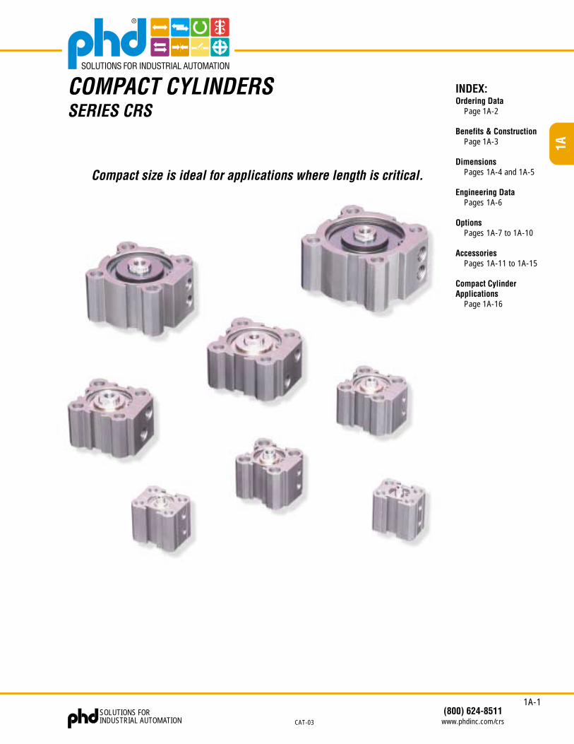
COMPACT CYLINDERSSERIES CRS
INDEX:Ordering Data
Page 1A-2
Benefits & ConstructionPage 1A-3
DimensionsPages 1A-4 and 1A-5
Engineering DataPages 1A-6
OptionsPages 1A-7 to 1A-10
AccessoriesPages 1A-11 to 1A-15
Compact CylinderApplications
Page 1A-16
Compact size is ideal for applications where length is critical.
1A-2
1A
SOLUTIONS FORINDUSTRIAL AUTOM
ATION(800) 624-8511
ww
w.phdinc.com
/crsCAT-03
ORDERING DATA: SERIES CRS COMPACT CYLINDERS
1216202532405063
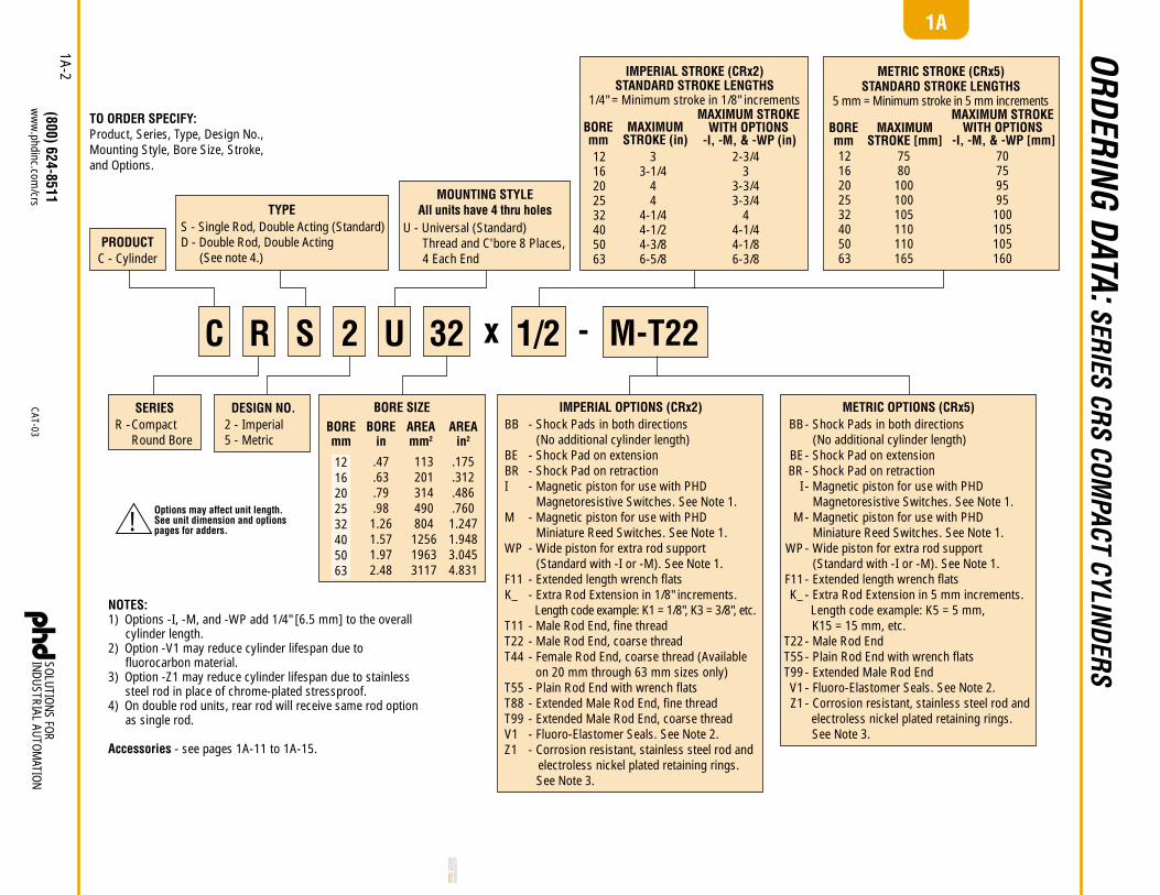
TO ORDER SPECIFY:Product, Series, Type, Design No.,Mounting Style, Bore Size, Stroke,and Options.
x -C R S 2 U 32 M-T221/2
NOTES:1) Options -I, -M, and -WP add 1/4" [6.5 mm] to the overall
cylinder length.2) Option -V1 may reduce cylinder lifespan due to
fluorocarbon material.3) Option -Z1 may reduce cylinder lifespan due to stainless
steel rod in place of chrome-plated stressproof.4) On double rod units, rear rod will receive same rod option
as single rod.
Accessories - see pages 1A-11 to 1A-15.
BB
BEBRI
M
WP
F11K_
T11T22T44
T55T88T99V1Z1
- Shock Pads in both directions (No additional cylinder length)- Shock Pad on extension- Shock Pad on retraction- Magnetic piston for use with PHD Magnetoresistive Switches. See Note 1.- Magnetic piston for use with PHD Miniature Reed Switches. See Note 1.- Wide piston for extra rod support (Standard with -I or -M). See Note 1.- Extended length wrench flats- Extra Rod Extension in 1/8" increments. Length code example: K1 = 1/8", K3 = 3/8", etc.- Male Rod End, fine thread- Male Rod End, coarse thread- Female Rod End, coarse thread (Available
on 20 mm through 63 mm sizes only)- Plain Rod End with wrench flats- Extended Male Rod End, fine thread- Extended Male Rod End, coarse thread- Fluoro-Elastomer Seals. See Note 2.- Corrosion resistant, stainless steel rod and electroless nickel plated retaining rings.
See Note 3.
IMPERIAL OPTIONS (CRx2)BB
BEBR
I
M
WP
F11K_
T22T55T99V1Z1
- Shock Pads in both directions (No additional cylinder length)- Shock Pad on extension- Shock Pad on retraction- Magnetic piston for use with PHD Magnetoresistive Switches. See Note 1.- Magnetic piston for use with PHD Miniature Reed Switches. See Note 1.- Wide piston for extra rod support (Standard with -I or -M). See Note 1.- Extended length wrench flats- Extra Rod Extension in 5 mm increments. Length code example: K5 = 5 mm,
K15 = 15 mm, etc.- Male Rod End- Plain Rod End with wrench flats- Extended Male Rod End- Fluoro-Elastomer Seals. See Note 2.- Corrosion resistant, stainless steel rod and electroless nickel plated retaining rings.
See Note 3.
METRIC OPTIONS (CRx5)SERIESCompactRound Bore
R - AREAin2
.175
.312
.486
.7601.2471.9483.0454.831
STANDARD STROKE LENGTHS5 mm = Minimum stroke in 5 mm increments
METRIC STROKE (CRx5)STANDARD STROKE LENGTHS
1/4" = Minimum stroke in 1/8" increments
BOREmm1216202532405063
MAXIMUMSTROKE (in)
33-1/4
44
4-1/44-1/24-3/86-5/8
MAXIMUM STROKEWITH OPTIONS
-I, -M, & -WP (in)2-3/4
33-3/43-3/4
44-1/44-1/86-3/8
IMPERIAL STROKE (CRx2)
MOUNTING STYLEAll units have 4 thru holes
U - Universal (Standard) Thread and C'bore 8 Places, 4 Each End
TYPES - Single Rod, Double Acting (Standard)D - Double Rod, Double Acting (See note 4.)
PRODUCTC - Cylinder
DESIGN NO.2 - Imperial5 - Metric
BOREin
.47
.63
.79
.981.261.571.972.48
BOREmm
AREAmm2
113201314490804
125619633117
BOREmm1216202532405063
MAXIMUMSTROKE [mm]
7580
100100105110110165
MAXIMUM STROKEWITH OPTIONS
-I, -M, & -WP [mm]70759595
100105105160
BORE SIZE
!Options may affect unit length.See unit dimension and optionspages for adders.
1A-3
1A
(800) 624-8511www.phdinc.com/crs
SOLUTIONS FORINDUSTRIAL AUTOMATION CAT-03
1
3
4
2
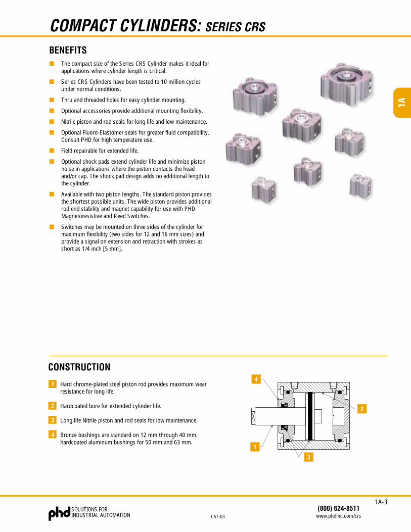
COMPACT CYLINDERS: SERIES CRS
BENEFITS■ The compact size of the Series CRS Cylinder makes it ideal for
applications where cylinder length is critical.
■ Series CRS Cylinders have been tested to 10 million cyclesunder normal conditions.
■ Thru and threaded holes for easy cylinder mounting.
■ Optional accessories provide additional mounting flexibility.
■ Nitrile piston and rod seals for long life and low maintenance.
■ Optional Fluoro-Elastomer seals for greater fluid compatibility.Consult PHD for high temperature use.
■ Field repairable for extended life.
■ Optional shock pads extend cylinder life and minimize pistonnoise in applications where the piston contacts the headand/or cap. The shock pad design adds no additional length tothe cylinder.
■ Available with two piston lengths. The standard piston providesthe shortest possible units. The wide piston provides additionalrod end stability and magnet capability for use with PHDMagnetoresistive and Reed Switches.
■ Switches may be mounted on three sides of the cylinder formaximum flexibility (two sides for 12 and 16 mm sizes) andprovide a signal on extension and retraction with strokes asshort as 1/4 inch [5 mm].
CONSTRUCTION
1 Hard chrome-plated steel piston rod provides maximum wearresistance for long life.
2 Hardcoated bore for extended cylinder life.
3 Long life Nitrile piston and rod seals for low maintenance.
4 Bronze bushings are standard on 12 mm through 40 mm,hardcoated aluminum bushings for 50 mm and 63 mm.
1A-4
1A
SOLUTIONS FORINDUSTRIAL AUTOMATION
(800) 624-8511www.phdinc.com/crs CAT-03
.157[4.0]
F + STROKE
H
.157[4.0]
+ STROKEDOUBLE ROD ONLY
2X G 2X R PORT
CL
P
8X(N)
EXTEND RETRACT
STANDARD REAR PORT LOCATION FOR32 mm AND 40 mm BORE UNITS WITHLESS THAN .500 [15.0] STROKE
3X SWITCH MTG SLOT
B A
C
B
A
D
E
J THREADØ K RODL WRENCH FLAT x .125[3.0] LONG
8X DRILL & C'BORE FOR MSOCKET HEAD CAP SCREW
N THREAD
H
2X R PORT2X G
.157[4.0]
F + STROKE .157[4.0]
+ STROKEDOUBLE ROD ONLY
CL
8X(N)
RETRACTEXTEND
AB
J THREADØ K RODL WRENCH FLAT x .125 [3.0] LONG
3X SWITCH MTG SLOT8X DRILL & C'BORE FOR MSOCKET HEAD CAP SCREW
N THREAD
D
E
CBA
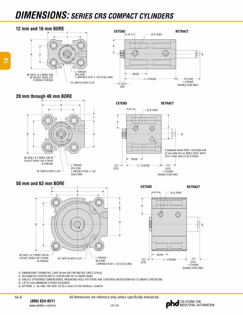
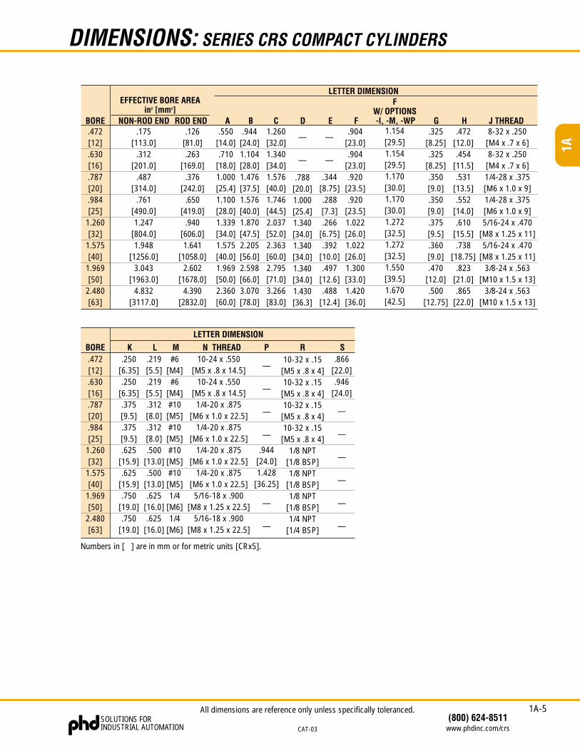
DIMENSIONS: SERIES CRS COMPACT CYLINDERS
12 mm and 16 mm BORE
50 mm and 63 mm BORE
20 mm through 40 mm BORE
C
S
AB
J THREADØ K RODL WRENCH FLAT x .125 [3.0] LONG
2X SWITCH MTG SLOT
8X DRILL & C'BORE FORM SOCKET HEAD CAP
SCREW N THREAD F + STROKE
H
2X R PORT
CL
.157 [4.0]+ STROKE
DOUBLE ROD ONLY
2X G
8X(N)
EXTEND RETRACT
.157[4.0]
1) DIMENSIONS SHOWN IN [ ] ARE IN mm OR FOR METRIC UNITS [CRx5]2) DESIGNATED CENTERLINE IS CENTERLINE OF CYLINDER BORE3) UNLESS OTHERWISE DIMENSIONED, MOUNTING HOLE PATTERNS ARE CENTERED ON DESIGNATED CYLINDER CENTERLINE4) 1/4" [5 mm] MINIMUM STROKE REQUIRED5) OPTIONS -I, -M, AND -WP ADD 1/4" [6.5 mm] TO THE OVERALL LENGTH
All dimensions are reference only unless specifically toleranced.
1A-5
1A
(800) 624-8511www.phdinc.com/crs
SOLUTIONS FORINDUSTRIAL AUTOMATION CAT-03
.472[12].630[16].787[20].984[25]
1.260[32]
1.575[40]
1.969[50]
2.480[63]
BORE A.550
[14.0].710
[18.0]1.000[25.4]1.100[28.0]1.339[34.0]1.575[40.0]1.969[50.0]2.360[60.0]
B C D E
LETTER DIMENSION
NON-ROD END ROD END
.788[20.0]1.000[25.4]1.340[34.0]1.340[34.0]1.340[34.0]1.430[36.3]
.904[23.0].904
[23.0].920
[23.5].920
[23.5]1.022[26.0]1.022[26.0]1.300[33.0]1.420[36.0]
F
#6[M4]#6
[M4]#10[M5]#10[M5]#10[M5]#10[M5]1/4
[M6]1/4
[M6]
G.325
[8.25].325
[8.25].350[9.0].350[9.0].375[9.5].360[9.0].470
[12.0].500
[12.75]
H8-32 x .250
[M4 x .7 x 6]8-32 x .250
[M4 x .7 x 6]1/4-28 x .375[M6 x 1.0 x 9]1/4-28 x .375[M6 x 1.0 x 9]5/16-24 x .470
[M8 x 1.25 x 11]5/16-24 x .470
[M8 x 1.25 x 11]3/8-24 x .563
[M10 x 1.5 x 13]3/8-24 x .563
[M10 x 1.5 x 13]
.250[6.35].250
[6.35].375[9.5].375[9.5].625
[15.9].625
[15.9].750
[19.0].750
[19.0]
K.219[5.5].219[5.5].312[8.0].312[8.0].500
[13.0].500
[13.0].625
[16.0].625
[16.0]
L
FW/ OPTIONS-I, -M, -WP
M
.175[113.0]
.312[201.0]
.487[314.0]
.761[490.0]1.247
[804.0]1.948
[1256.0]3.043
[1963.0]4.832
[3117.0]
.126[81.0].263
[169.0].376
[242.0].650
[419.0].940
[606.0]1.641
[1058.0]2.602
[1678.0]4.390
[2832.0]
.944[24.0]1.104[28.0]1.476[37.5]1.576[40.0]1.870[47.5]2.205[56.0]2.598[66.0]3.070[78.0]
1.260[32.0]1.340[34.0]1.576[40.0]1.746[44.5]2.037[52.0]2.363[60.0]2.795[71.0]3.266[83.0]
.344[8.75].288[7.3].266
[6.75].392
[10.0].497
[12.6].488
[12.4]
1.154[29.5]1.154[29.5]1.170[30.0]1.170[30.0]1.272[32.5]1.272[32.5]1.550[39.5]1.670[42.5]
.472[12.0].454
[11.5].531
[13.5].552
[14.0].610
[15.5].738
[18.75].823
[21.0].865
[22.0]
J THREAD
N THREAD10-24 x .550
[M5 x .8 x 14.5]10-24 x .550
[M5 x .8 x 14.5]1/4-20 x .875
[M6 x 1.0 x 22.5]1/4-20 x .875
[M6 x 1.0 x 22.5]1/4-20 x .875
[M6 x 1.0 x 22.5]1/4-20 x .875
[M6 x 1.0 x 22.5]5/16-18 x .900
[M8 x 1.25 x 22.5]5/16-18 x .900
[M8 x 1.25 x 22.5]
R10-32 x .15
[M5 x .8 x 4]10-32 x .15
[M5 x .8 x 4]10-32 x .15
[M5 x .8 x 4]10-32 x .15
[M5 x .8 x 4]1/8 NPT
[1/8 BSP]1/8 NPT
[1/8 BSP]1/8 NPT
[1/8 BSP]1/4 NPT
[1/4 BSP]
S.866
[22.0].946
[24.0]
.472[12].630[16].787[20].984[25]
1.260[32]
1.575[40]
1.969[50]
2.480[63]
BORE
Numbers in [ ] are in mm or for metric units [CRx5].
—
—
—
—
—
—
—
—
—
—
LETTER DIMENSION
.944[24.0]1.428
[36.25]
P
—
—
—
—
—
—
EFFECTIVE BORE AREAin2 [mm2]
DIMENSIONS: SERIES CRS COMPACT CYLINDERS
All dimensions are reference only unless specifically toleranced.
1A-6
1A
SOLUTIONS FORINDUSTRIAL AUTOMATION
(800) 624-8511www.phdinc.com/crs CAT-03
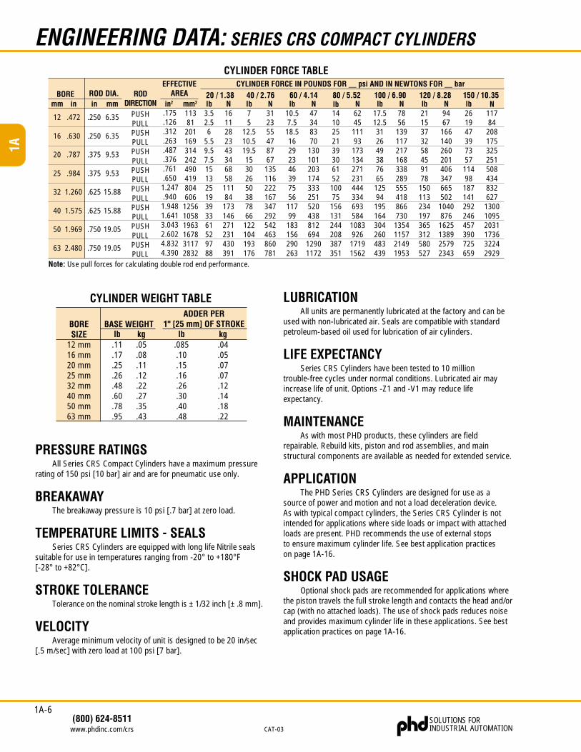
.085.10.15.16.26.30.40.48
ADDER PER1" [25 mm] OF STROKE
.05
.08
.11
.12
.22
.27
.35
.43
BASE WEIGHT
12 mm16 mm20 mm25 mm32 mm40 mm50 mm63 mm
BORESIZE kglb
.11
.17
.25
.26
.48
.60
.78
.95
kglb.04.05.07.07.12.14.18.22
CYLINDER FORCE TABLE
Note: Use pull forces for calculating double rod end performance.
PUSHPULLPUSHPULLPUSHPULLPUSHPULLPUSHPULLPUSHPULLPUSHPULLPUSHPULL
RODDIRECTION
.250
.250
.375
.375
.625
.625
.750
.750
ROD DIA.EFFECTIVE
AREA
.472
.630
.787
.984
1.260
1.575
1.969
2.480
BOREmm in
12
16
20
25
32
40
50
63
6.35
6.35
9.53
9.53
15.88
15.88
19.05
19.05
mmin
CYLINDER FORCE IN POUNDS FOR __ psi AND IN NEWTONS FOR __ bar20 / 1.38 40 / 2.76 60 / 4.14 80 / 5.52 100 / 6.90 120 / 8.28 150 / 10.35lb3.52.56
5.59.57.515132519393361529788
1611282343346858
11184
173146271231430391
N312355478767
135116222167347292542463860781
Nlb75
12.510.519.515302650387866
122104193176
N47348370
130101203174333251520438812694
12901172
10.57.5
18.516292346397556
11799
183156290263
lb N6245
11193
173134271231444334693584
1083926
17191562
1410252139306152
10075
156131244208387351
lb N7856
139117217168338289555418866730
1354115721491953
17.512.5312649387665
12594
195164304260483439
lb N9467
16614026020140634766550210408761625138925792343
2115373258459178
150113234197365312580527
lb N11784
208175325251508434832627
130010952031173632242929
261947397357
11498
187141292246457390725659
lbin2
.175
.126
.312
.263
.487
.376
.761
.6501.247.940
1.9481.6413.0432.6024.8324.390
11381
201169314242490419804606
125610581963167831172832
mm2
ENGINEERING DATA: SERIES CRS COMPACT CYLINDERS
PRESSURE RATINGSAll Series CRS Compact Cylinders have a maximum pressure
rating of 150 psi [10 bar] air and are for pneumatic use only.
BREAKAWAYThe breakaway pressure is 10 psi [.7 bar] at zero load.
TEMPERATURE LIMITS - SEALSSeries CRS Cylinders are equipped with long life Nitrile seals
suitable for use in temperatures ranging from -20° to +180°F[-28° to +82°C].
STROKE TOLERANCETolerance on the nominal stroke length is ± 1/32 inch [± .8 mm].
VELOCITYAverage minimum velocity of unit is designed to be 20 in/sec
[.5 m/sec] with zero load at 100 psi [7 bar].
LUBRICATIONAll units are permanently lubricated at the factory and can be
used with non-lubricated air. Seals are compatible with standardpetroleum-based oil used for lubrication of air cylinders.
LIFE EXPECTANCYSeries CRS Cylinders have been tested to 10 million
trouble-free cycles under normal conditions. Lubricated air mayincrease life of unit. Options -Z1 and -V1 may reduce lifeexpectancy.
MAINTENANCEAs with most PHD products, these cylinders are field
repairable. Rebuild kits, piston and rod assemblies, and mainstructural components are available as needed for extended service.
APPLICATIONThe PHD Series CRS Cylinders are designed for use as a
source of power and motion and not a load deceleration device.As with typical compact cylinders, the Series CRS Cylinder is notintended for applications where side loads or impact with attachedloads are present. PHD recommends the use of external stopsto ensure maximum cylinder life. See best application practiceson page 1A-16.
SHOCK PAD USAGEOptional shock pads are recommended for applications where
the piston travels the full stroke length and contacts the head and/orcap (with no attached loads). The use of shock pads reduces noiseand provides maximum cylinder life in these applications. See bestapplication practices on page 1A-16.
CYLINDER WEIGHT TABLE
1A-7
1A
(800) 624-8511www.phdinc.com/crs
SOLUTIONS FORINDUSTRIAL AUTOMATION CAT-03
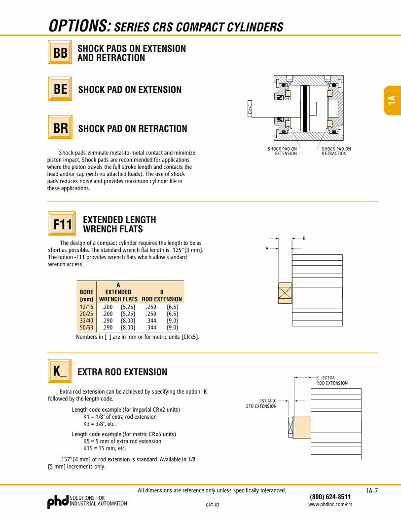
Extra rod extension can be achieved by specifying the option -Kfollowed by the length code.
Length code example (for imperial CRx2 units)K1 = 1/8" of extra rod extensionK3 = 3/8", etc.
Length code example (for metric CRx5 units)K5 = 5 mm of extra rod extensionK15 = 15 mm, etc.
.157" [4 mm] of rod extension is standard. Available in 1/8"[5 mm] increments only.
.250
.250
.344
.344
12/1620/2532/4050/63
BORE[mm]
AEXTENDED
WRENCH FLATS.200.200.290.290
BROD EXTENSION
[5.25][5.25][8.00][8.00]
[6.5][6.5][9.0][9.0]
Numbers in [ ] are in mm or for metric units [CRx5].
.157 [4.0]STD EXTENSION
K_ EXTRAROD EXTENSION
B
A
SHOCK PAD ON EXTENSION
SHOCK PAD ON RETRACTION
SHOCK PADS ON EXTENSIONAND RETRACTION
OPTIONS: SERIES CRS COMPACT CYLINDERS
BB
BE
BR
Shock pads eliminate metal-to-metal contact and minimizepiston impact. Shock pads are recommended for applicationswhere the piston travels the full stroke length and contacts thehead and/or cap (with no attached loads). The use of shockpads reduces noise and provides maximum cylinder life inthese applications.
The design of a compact cylinder requires the length to be asshort as possible. The standard wrench flat length is .125" [3 mm].The option -F11 provides wrench flats which allow standardwrench access.
EXTENDED LENGTHWRENCH FLATSF11
EXTRA ROD EXTENSIONK_
SHOCK PAD ONEXTENSION
SHOCK PAD ONRETRACTION
All dimensions are reference only unless specifically toleranced.
1A-8
1A
SOLUTIONS FORINDUSTRIAL AUTOMATION
(800) 624-8511www.phdinc.com/crs CAT-03
MINIMUM STROKE FOREXTEND OR RETRACT
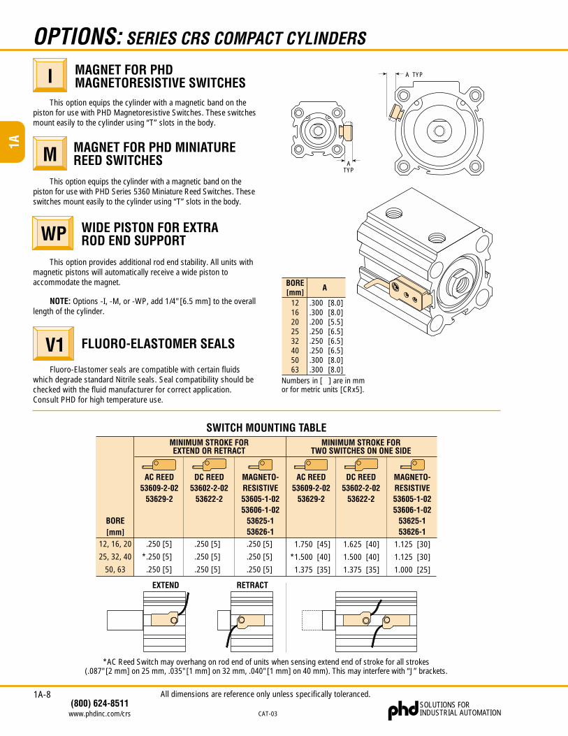
SWITCH MOUNTING TABLE
*AC Reed Switch may overhang on rod end of units when sensing extend end of stroke for all strokes(.087" [2 mm] on 25 mm, .035" [1 mm] on 32 mm, .040" [1 mm] on 40 mm). This may interfere with “J” brackets.
12, 16, 20
25, 32, 40
50, 63
BORE[mm]
MAGNETO-RESISTIVE53605-1-0253606-1-02
53625-153626-1
DC REED53602-2-02
53622-2
AC REED53609-2-02
53629-2
.250 [5]
*.250 [5]
.250 [5]
MINIMUM STROKE FORTWO SWITCHES ON ONE SIDE
MAGNETO-RESISTIVE53605-1-0253606-1-02
53625-153626-1
DC REED53602-2-02
53622-2
AC REED53609-2-02
53629-2
1.750 [45]
*1.500 [40]
1.375 [35]
1.625 [40]
1.500 [40]
1.375 [35]
1.125 [30]
1.125 [30]
1.000 [25]
.250 [5]
.250 [5]
.250 [5]
.250 [5]
.250 [5]
.250 [5]
EXTEND RETRACT
Fluoro-Elastomer seals are compatible with certain fluidswhich degrade standard Nitrile seals. Seal compatibility should bechecked with the fluid manufacturer for correct application.Consult PHD for high temperature use.
A TYP
ATYP
OPTIONS: SERIES CRS COMPACT CYLINDERS
MAGNET FOR PHDMAGNETORESISTIVE SWITCHESI
MAGNET FOR PHD MINIATUREREED SWITCHESM
WIDE PISTON FOR EXTRAROD END SUPPORTWP
NOTE: Options -I, -M, or -WP, add 1/4" [6.5 mm] to the overalllength of the cylinder.
FLUORO-ELASTOMER SEALSV1
This option equips the cylinder with a magnetic band on thepiston for use with PHD Series 5360 Miniature Reed Switches. Theseswitches mount easily to the cylinder using “T” slots in the body.
This option equips the cylinder with a magnetic band on thepiston for use with PHD Magnetoresistive Switches. These switchesmount easily to the cylinder using “T” slots in the body.
This option provides additional rod end stability. All units withmagnetic pistons will automatically receive a wide piston toaccommodate the magnet. BORE
[mm]1216202532405063
.300 [8.0]
.300 [8.0]
.200 [5.5]
.250 [6.5]
.250 [6.5]
.250 [6.5]
.300 [8.0]
.300 [8.0]
A
Numbers in [ ] are in mmor for metric units [CRx5].
All dimensions are reference only unless specifically toleranced.
1A-9
1A
(800) 624-8511www.phdinc.com/crs
SOLUTIONS FORINDUSTRIAL AUTOMATION CAT-03
OPTIONS: SERIES CRS COMPACT CYLINDERS
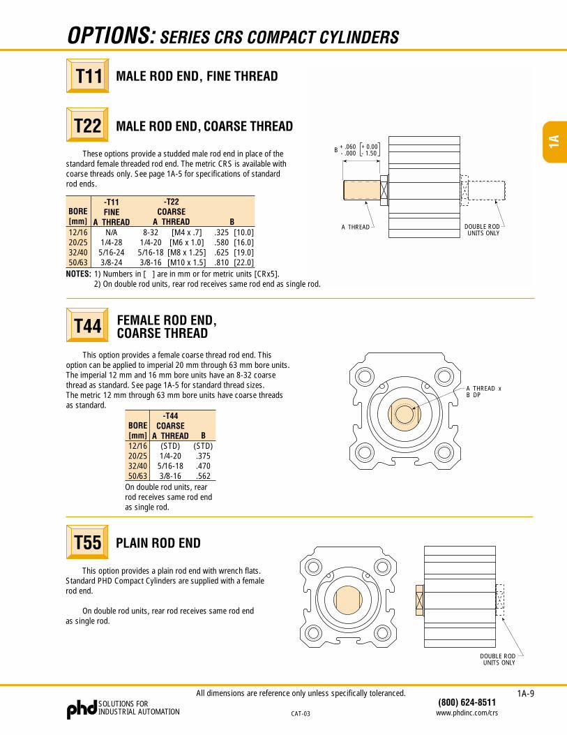
These options provide a studded male rod end in place of thestandard female threaded rod end. The metric CRS is available withcoarse threads only. See page 1A-5 for specifications of standardrod ends.
MALE ROD END, FINE THREAD
MALE ROD END, COARSE THREADT22
T11
A THREAD
B + .060- .000
+ 0.00- 1.50
DOUBLE RODUNITS ONLY
This option provides a female coarse thread rod end. Thisoption can be applied to imperial 20 mm through 63 mm bore units.The imperial 12 mm and 16 mm bore units have an 8-32 coarsethread as standard. See page 1A-5 for standard thread sizes.The metric 12 mm through 63 mm bore units have coarse threadsas standard.
FEMALE ROD END,COARSE THREADT44
BORE[mm]12/1620/2532/4050/63
-T44COARSE
A THREAD B(STD).375.470.562
(STD)1/4-205/16-183/8-16
On double rod units, rearrod receives same rod endas single rod.
A THREAD xB DP
This option provides a plain rod end with wrench flats.Standard PHD Compact Cylinders are supplied with a femalerod end.
On double rod units, rear rod receives same rod endas single rod.
PLAIN ROD ENDT55
DOUBLE RODUNITS ONLY
All dimensions are reference only unless specifically toleranced.
12/1620/2532/4050/63
-T11FINE
A THREADN/A
1/4-285/16-243/8-24
-T22COARSE
A THREAD8-32
1/4-205/16-183/8-16
B.325.580.625.810
NOTES: 1) Numbers in [ ] are in mm or for metric units [CRx5].2) On double rod units, rear rod receives same rod end as single rod.
[M4 x .7][M6 x 1.0][M8 x 1.25][M10 x 1.5]
[10.0][16.0][19.0][22.0]
BORE[mm]
1A-10
1A
SOLUTIONS FORINDUSTRIAL AUTOMATION
(800) 624-8511www.phdinc.com/crs CAT-03
OPTIONS & ACCESSORIES: SERIES CRS COMPACT CYLINDERS
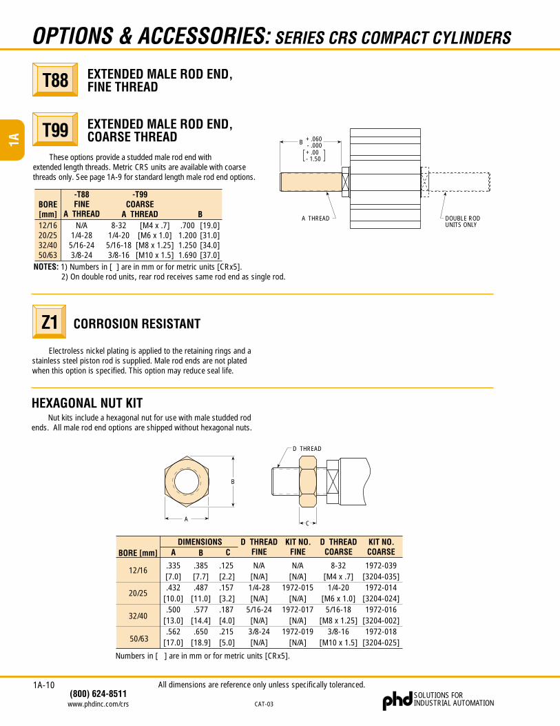
These options provide a studded male rod end withextended length threads. Metric CRS units are available with coarsethreads only. See page 1A-9 for standard length male rod end options.
EXTENDED MALE ROD END,FINE THREAD
EXTENDED MALE ROD END,COARSE THREAD
T88
T99
B.7001.2001.2501.690
12/1620/2532/4050/63
BORE[mm]
-T88FINE
A THREADN/A
1/4-285/16-243/8-24
-T99COARSE
A THREAD[19.0][31.0][34.0][37.0]
NOTES: 1) Numbers in [ ] are in mm or for metric units [CRx5].2) On double rod units, rear rod receives same rod end as single rod.
8-321/4-205/16-183/8-16
[M4 x .7][M6 x 1.0][M8 x 1.25][M10 x 1.5]
CORROSION RESISTANT
Electroless nickel plating is applied to the retaining rings and astainless steel piston rod is supplied. Male rod ends are not platedwhen this option is specified. This option may reduce seal life.
Z1
HEXAGONAL NUT KITNut kits include a hexagonal nut for use with male studded rod
ends. All male rod end options are shipped without hexagonal nuts.
A
B
C
D THREAD
12/16
20/25
32/40
50/63
BORE [mm]DIMENSIONS
Numbers in [ ] are in mm or for metric units [CRx5].
N/A[N/A]
1972-015[N/A]
1972-017[N/A]
1972-019[N/A]
KIT NO.FINE
8-32[M4 x .7]
1/4-20[M6 x 1.0]
5/16-18[M8 x 1.25]
3/8-16[M10 x 1.5]
D THREADCOARSE
1972-039[3204-035]1972-014
[3204-024]1972-016
[3204-002]1972-018
[3204-025]
KIT NO.COARSE
N/A[N/A]
1/4-28[N/A]
5/16-24[N/A]
3/8-24[N/A]
D THREADFINEC
.125[2.2].157[3.2].187[4.0].215[5.0]
B.385[7.7].487
[11.0].577
[14.4].650
[18.9]
A
.335[7.0].432
[10.0].500
[13.0].562
[17.0]
A THREAD
B + .060- .000+ .00- 1.50
DOUBLE RODUNITS ONLY
All dimensions are reference only unless specifically toleranced.
1A-11
1A
(800) 624-8511www.phdinc.com/crs
SOLUTIONS FORINDUSTRIAL AUTOMATION CAT-03
ACCESSORIES: SERIES CRS COMPACT CYLINDERS
12 - 25 mm 32-63 mm
CL CL
HOLE FORØ J mm PIN
G
B
A
F RAD
E
C
D
2X H SHCS(SUPPLIED IN KIT)
C
D
1/2 D
4X H SHCS(SUPPLIED IN
KIT)
F
ABRONZEBUSHING
G
B
HOLE FORØ J mm PIN
CL
CL
CLE
CL
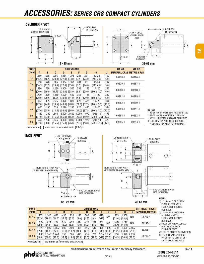
CYLINDER PIVOT
DIMENSIONSB
Numbers in [ ] are in mm or for metric units [CRx5].
12
16
20
25
32
40
50
63
BORE[mm] A
.650[16.5].650
[16.5].790
[20.0].790
[20.0]1.065[27.0]1.065[27.0]1.460[37.0]1.460[37.0]
.638[16.5].678
[17.5].750
[19.0].800
[20.5].935
[24.0]1.105[28.0]1.300[33.0]1.500[38.0]
C.905
[23.0].905
[23.0]1.250
[31.75]1.250
[31.75].526
[13.5].526
[13.5].646
[16.5].646
[16.5]
D1.064[27.0]1.064[27.0]1.500[38.0]1.500[38.0]1.870[48.0]2.210[56.0]2.600[66.0]3.000[76.0]
E1.276[33.0]1.356[35.0]1.500[38.0]1.600[41.0]1.870[48.0]2.210[56.0]2.600[66.0]3.000[76.0]
F.281[7.5].281[7.5].355[9.0].355[9.0].820
[21.0].820
[21.0]1.000[25.5]1.000[25.5]
G.931
[24.0].931
[24.0]1.145[29.0]1.145[29.0]1.475[37.5]1.475[37.5]1.970[50.0]1.970[50.0]
H10-24
[M5 x .8]10-24
[M5 x .8]1/4-20
[M6 x 1.0]1/4-20
[M6 x 1.0]1/4-20
[M6 x 1.0]1/4-20
[M6 x 1.0]5/16-18
[M8 x 1.25]5/16-18
[M8 x 1.25]
J.197[5.0].197[5.0].237[6.0].237[6.0].394
[10.0].394
[10.0].473
[12.0].473
[12.0]
KIT NO.IMPERIAL CRx2
KIT NO.METRIC CRx5
60278-1
60279-1
60280-1
60281-1
60282-1
60283-1
60284-1
60285-1
60286-1
60287-1
60288-1
60289-1
60290-1
60291-1
60292-1
60293-1
NOTES:1) 12-25 mm IS BRITE ZINC PLATED STEEL2) 32-63 mm IS ANODIZED ALUMINUM
WITH LUBRICATED BRONZE BUSHINGS3) FULCRUM PIN NOT INCLUDED (SEE
“FULCRUM PIN KITS” TO PURCHASE)
BASE PIVOT
12 - 25 mm 32-63 mm
C
A
D
HOLE FOR Ø F mm PIN(PIN SUPPLIED WITH KIT)
B
PHD CYLINDER PIVOTNOT INCLUDED**G
E*
H
LM
2X BRONZEBUSHING
2X BRONZEBUSHING
4X THRU HOLEFOR J SHCS
N K M L
H
D
A
C
HOLE FOR Ø F mm PIN(PIN SUPPLIED WITH KIT)
*EPHD CYLINDER PIVOTNOT INCLUDED
B
CL
CLCL
2X THRU HOLEFOR J SHCS
CL
CL
CLCL
CL
**G
DIMENSIONSB
Numbers in [ ] are in mm or for metric units [CRx5].
BORE[mm] A
.865[22.0]1.000[25.5]1.375[35.0]1.890[48.0]
1.145[29.0]1.355[34.5]1.800[46.0]2.365[60.0]
C.650
[16.5].790
[20.0]1.065[27.0]1.460[37.0]
D.490
[12.5].630
[16.0].600
[15.2].755
[19.2]
E.220[5.6].260[6.5].400
[10.2].505
[13.0]
F G.060[1.5].040[1.0].156[4.0].236[6.0]
H#10[M5]1/4
[M6]1/4
[M6]5/16[M8]
J
12/16
20/25
32/40
50/63
1.695[43.0]2.265[57.5]
K
N/A
N/A
L.905
[23.0]1.250
[31.75].530
[13.5].650
[16.5]
M1.300[33.0]1.730[44.0]1.490[38.0]1.970[50.0]
NKIT: CRx2x, CRx5xIMPERIAL/METRIC
2.165[55.0]2.835[72.0]
N/A
N/A
60294-1
60295-1
60296-1
60297-1
.375[9.5].435
[11.0].510
[13.0].709
[18.0]
.197[5.0].237[6.0].394
[10.0].473
[12.0]
NOTES:1) 12-25 mm IS BRITE ZINC
PLATED STEEL WITHLUBRICATED BRONZEBUSHINGS
2) 32-63 mm IS ANODIZEDALUMINUM WITHLUBRICATED BRONZEBUSHINGS
3) FULCRUM PIN INCLUDED.DOES NOT INCLUDECYLINDER PIVOT.
4) *E IS TO CENTER OF PIVOT PIN5) **G IS FROM CENTER OF
PIVOT PIN TO CENTER OFFIRST MOUNTING HOLE
All dimensions are reference only unless specifically toleranced.
1A-12
1A
SOLUTIONS FORINDUSTRIAL AUTOMATION
(800) 624-8511www.phdinc.com/crs CAT-03
ACCESSORIES: SERIES CRS COMPACT CYLINDERS
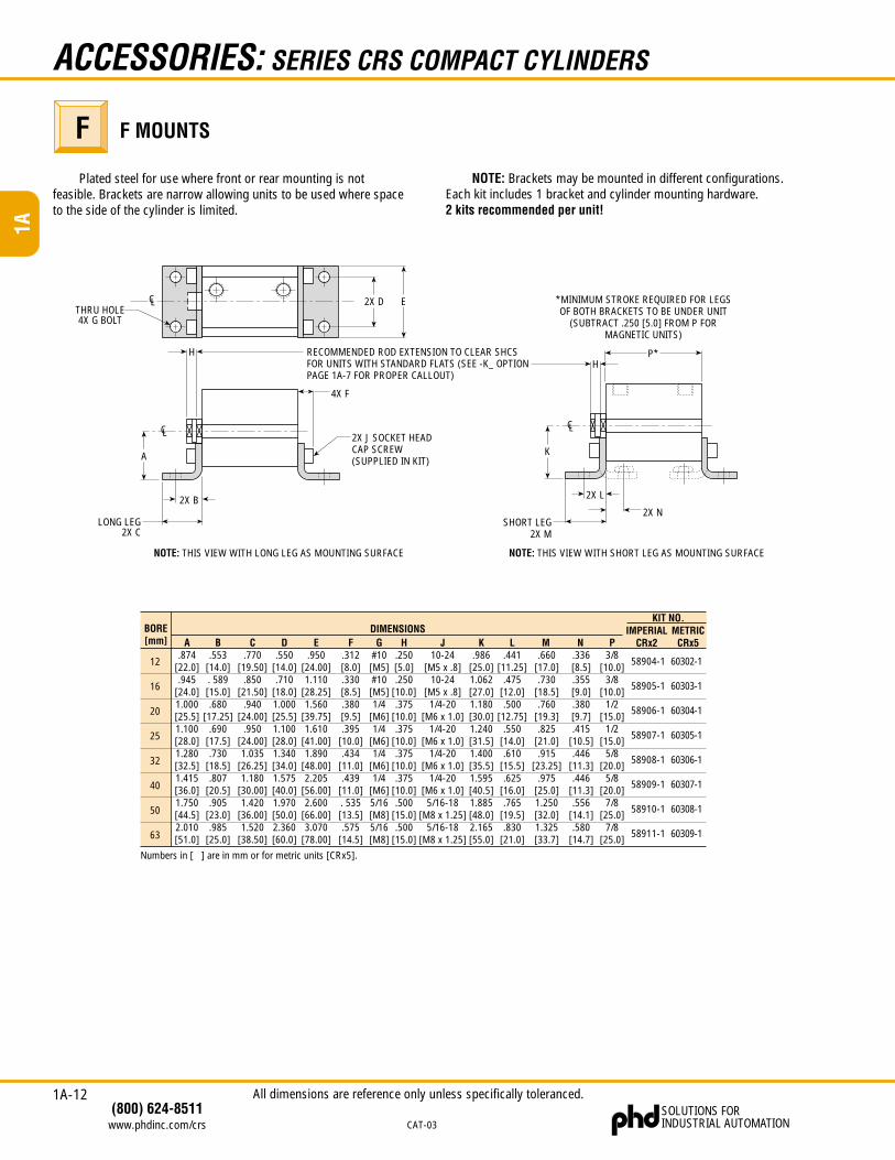
F MOUNTSFPlated steel for use where front or rear mounting is not
feasible. Brackets are narrow allowing units to be used where spaceto the side of the cylinder is limited.
NOTE: Brackets may be mounted in different configurations.Each kit includes 1 bracket and cylinder mounting hardware.2 kits recommended per unit!
K
NOTE: THIS VIEW WITH SHORT LEG AS MOUNTING SURFACE
2X L
2X NSHORT LEG
2X M
P*
*MINIMUM STROKE REQUIRED FOR LEGSOF BOTH BRACKETS TO BE UNDER UNIT
(SUBTRACT .250 [5.0] FROM P FORMAGNETIC UNITS)
2X D ETHRU HOLE4X G BOLT
A
RECOMMENDED ROD EXTENSION TO CLEAR SHCSFOR UNITS WITH STANDARD FLATS (SEE -K_ OPTIONPAGE 1A-7 FOR PROPER CALLOUT)
2X J SOCKET HEADCAP SCREW(SUPPLIED IN KIT)
2X B
LONG LEG2X C
H
4X F
NOTE: THIS VIEW WITH LONG LEG AS MOUNTING SURFACE
H
CL
CLCL
Numbers in [ ] are in mm or for metric units [CRx5].
BORE[mm]
12
16
20
25
32
40
50
63
KIT NO.
A.874
[22.0].945
[24.0]1.000[25.5]1.100[28.0]1.280[32.5]1.415[36.0]1.750[44.5]2.010[51.0]
B.553
[14.0]. 589[15.0].680
[17.25].690
[17.5].730
[18.5].807
[20.5].905
[23.0].985
[25.0]
C.770
[19.50].850
[21.50].940
[24.00].950
[24.00]1.035
[26.25]1.180
[30.00]1.420
[36.00]1.520
[38.50]
D.550
[14.0].710
[18.0]1.000[25.5]1.100[28.0]1.340[34.0]1.575[40.0]1.970[50.0]2.360[60.0]
E.950
[24.00]1.110
[28.25]1.560
[39.75]1.610
[41.00]1.890
[48.00]2.205
[56.00]2.600
[66.00]3.070
[78.00]
F.312[8.0].330[8.5].380[9.5].395
[10.0].434
[11.0].439
[11.0]. 535[13.5].575
[14.5]
G#10[M5]#10[M5]1/4
[M6]1/4
[M6]1/4
[M6]1/4
[M6]5/16[M8]5/16[M8]
H.250[5.0].250
[10.0].375
[10.0].375
[10.0].375
[10.0].375
[10.0].500
[15.0].500
[15.0]
10-24[M5 x .8]
10-24[M5 x .8]
1/4-20[M6 x 1.0]
1/4-20[M6 x 1.0]
1/4-20[M6 x 1.0]
1/4-20[M6 x 1.0]
5/16-18[M8 x 1.25]
5/16-18[M8 x 1.25]
J K.986
[25.0]1.062[27.0]1.180[30.0]1.240[31.5]1.400[35.5]1.595[40.5]1.885[48.0]2.165[55.0]
L.441
[11.25].475
[12.0].500
[12.75].550
[14.0].610
[15.5].625
[16.0].765
[19.5].830
[21.0]
M.660
[17.0].730
[18.5].760
[19.3].825
[21.0].915
[23.25].975
[25.0]1.250[32.0]1.325[33.7]
N.336[8.5].355[9.0].380[9.7].415
[10.5].446
[11.3].446
[11.3].556
[14.1].580
[14.7]
P3/8
[10.0]3/8
[10.0]1/2
[15.0]1/2
[15.0]5/8
[20.0]5/8
[20.0]7/8
[25.0]7/8
[25.0]
IMPERIALCRx2
58904-1
58905-1
58906-1
58907-1
58908-1
58909-1
58910-1
58911-1
METRICCRx5
60302-1
60303-1
60304-1
60305-1
60306-1
60307-1
60308-1
60309-1
DIMENSIONS
All dimensions are reference only unless specifically toleranced.
1A-13
1A
(800) 624-8511www.phdinc.com/crs
SOLUTIONS FORINDUSTRIAL AUTOMATION CAT-03
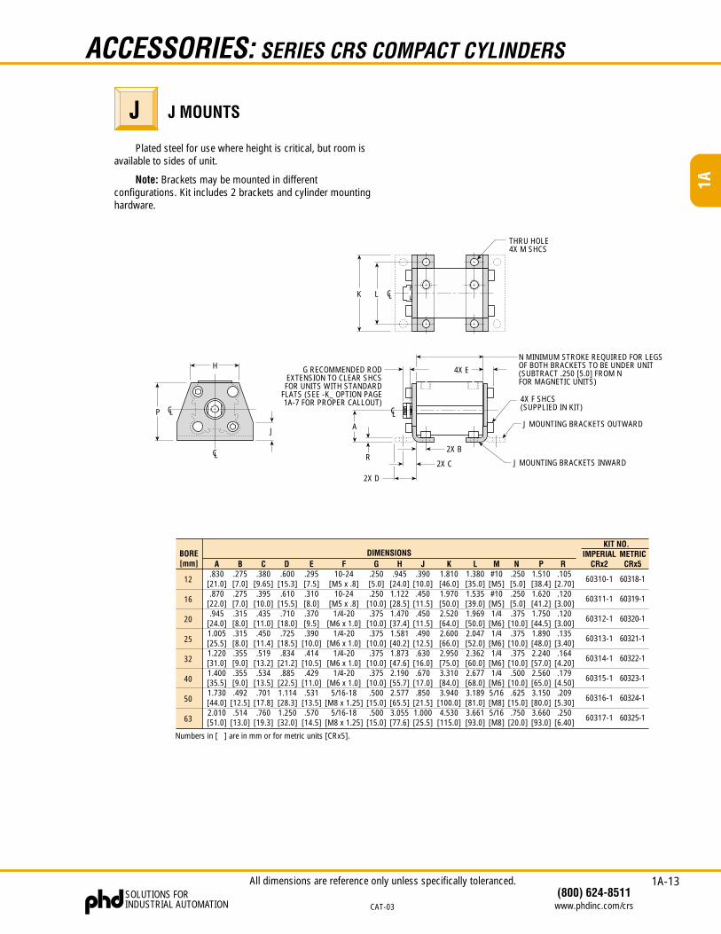
LK
THRU HOLE4X M SHCS
P
H
J A
R
2X D
2X C
2X B
G RECOMMENDED RODEXTENSION TO CLEAR SHCSFOR UNITS WITH STANDARD
FLATS (SEE -K_ OPTION PAGE1A-7 FOR PROPER CALLOUT)
4X E
N MINIMUM STROKE REQUIRED FOR LEGSOF BOTH BRACKETS TO BE UNDER UNIT(SUBTRACT .250 [5.0] FROM NFOR MAGNETIC UNITS)
4X F SHCS(SUPPLIED IN KIT)
J MOUNTING BRACKETS OUTWARD
CL
CL
CL
CL
J MOUNTING BRACKETS INWARD
ACCESSORIES: SERIES CRS COMPACT CYLINDERS
J MOUNTSJ
Note: Brackets may be mounted in differentconfigurations. Kit includes 2 brackets and cylinder mountinghardware.
Plated steel for use where height is critical, but room isavailable to sides of unit.
12
16
20
25
32
40
50
63
Numbers in [ ] are in mm or for metric units [CRx5].
A.830
[21.0].870
[22.0].945
[24.0]1.005[25.5]1.220[31.0]1.400[35.5]1.730[44.0]2.010[51.0]
B.275[7.0].275[7.0].315[8.0].315[8.0].355[9.0].355[9.0].492
[12.5].514
[13.0]
C.380
[9.65].395
[10.0].435
[11.0].450
[11.4].519
[13.2].534
[13.5].701
[17.8].760
[19.3]
D.600
[15.3].610
[15.5].710
[18.0].725
[18.5].834
[21.2].885
[22.5]1.114[28.3]1.250[32.0]
E.295[7.5].310[8.0].370[9.5].390
[10.0].414
[10.5].429
[11.0].531
[13.5].570
[14.5]
K1.810[46.0]1.970[50.0]2.520[64.0]2.600[66.0]2.950[75.0]3.310[84.0]3.940
[100.0]4.530
[115.0]
N.250[5.0].250[5.0].375
[10.0].375
[10.0].375
[10.0].500
[10.0].625
[15.0].750
[20.0]
IMPERIALCRx2
60310-1
60311-1
60312-1
60313-1
60314-1
60315-1
60316-1
60317-1
DIMENSIONSG
.250[5.0].250
[10.0].375
[10.0].375
[10.0].375
[10.0].375
[10.0].500
[15.0].500
[15.0]
L1.380[35.0]1.535[39.0]1.969[50.0]2.047[52.0]2.362[60.0]2.677[68.0]3.189[81.0]3.661[93.0]
R.105
[2.70].120
[3.00].120
[3.00].135
[3.40].164
[4.20].179
[4.50].209
[5.30].250
[6.40]
METRICCRx5
60318-1
60319-1
60320-1
60321-1
60322-1
60323-1
60324-1
60325-1
P1.510[38.4]1.620[41.2]1.750[44.5]1.890[48.0]2.240[57.0]2.560[65.0]3.150[80.0]3.660[93.0]
#10[M5]#10[M5]1/4
[M6]1/4
[M6]1/4
[M6]1/4
[M6]5/16[M8]5/16[M8]
MJ.390
[10.0].450
[11.5].450
[11.5].490
[12.5].630
[16.0].670
[17.0].850
[21.5]1.000[25.5]
H.945
[24.0]1.122[28.5]1.470[37.4]1.581[40.2]1.873[47.6]2.190[55.7]2.577[65.5]3.055[77.6]
F10-24
[M5 x .8]10-24
[M5 x .8]1/4-20
[M6 x 1.0]1/4-20
[M6 x 1.0]1/4-20
[M6 x 1.0]1/4-20
[M6 x 1.0]5/16-18
[M8 x 1.25]5/16-18
[M8 x 1.25]
KIT NO.BORE[mm]
All dimensions are reference only unless specifically toleranced.
1A-14
1A
SOLUTIONS FORINDUSTRIAL AUTOMATION
(800) 624-8511www.phdinc.com/crs CAT-03
ACCESSORIES: SERIES CRS COMPACT CYLINDERS
DIMENSIONS
Numbers in [ ] are in mm or for metric units [CRx5].
BORE[mm] A
.438[11.0].500
[12.7].625
[16.0].875
[22.2]
B.250[6.5].375[9.5].500
[12.5].625
[16.0]
C.885
[22.5]1.065[27.0]1.495[38.0]1.610[41.0]
D.215[5.5].255[6.5].355[9.0].430
[11.0]
E.219[5.5].250[6.5].313[8.0]. 438[11.0]
F G8-32
[M4 x .7]1/4-28
[M6 x 1.0]5/16-24
[M8 x 1.25]3/8-24
[M10 x 1.5]
KIT: CRx5xMETRIC
60234-1
60235-1
60236-1
60237-1
KIT: CRx2xIMPERIAL
59069-1
59070-1
59071-1
59072-1
12/16
20/25
32/40
50/63
.196[5.0].235[6.0].394
[10.0].471
[12.0]
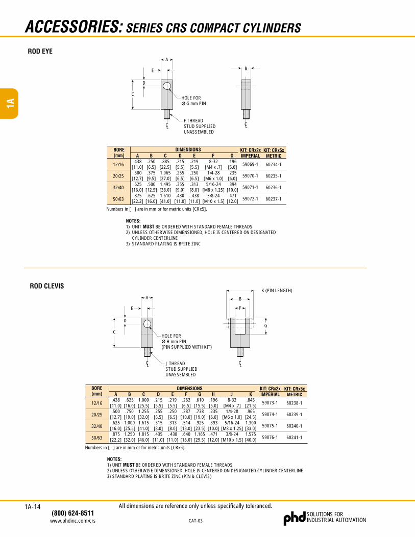
ROD EYE
NOTES:1) UNIT MUST BE ORDERED WITH STANDARD FEMALE THREADS2) UNLESS OTHERWISE DIMENSIONED, HOLE IS CENTERED ON DESIGNATED
CYLINDER CENTERLINE3) STANDARD PLATING IS BRITE ZINC
ROD CLEVISK (PIN LENGTH)
B
F
G
A
CHOLE FORØ H mm PIN(PIN SUPPLIED WITH KIT)
D
E
J THREADSTUD SUPPLIEDUNASSEMBLED
CL CL
DIMENSIONS
Numbers in [ ] are in mm or for metric units [CRx5].
HA.438
[11.0].500
[12.7].625
[16.0].875
[22.2]
B.625
[16.0].750
[19.0]1.000[25.5]1.250[32.0]
C1.000[25.5]1.255[32.0]1.615[41.0]1.815[46.0]
D.215[5.5].255[6.5].315[8.0].435
[11.0]
E.219[5.5].250[6.5].313[8.0]. 438[11.0]
F G.610
[15.5].738
[19.0].925
[23.5]1.165[29.5]
8-32[M4 x .7]
1/4-28[M6 x 1.0]
5/16-24[M8 x 1.25]
3/8-24[M10 x 1.5]
JKIT: CRx2xIMPERIAL
59073-1
59074-1
59075-1
59076-1
.262[6.5].387
[10.0].514
[13.0].640
[16.0]
K.845
[21.5].965
[24.5]1.300[33.0]1.575[40.0]
KIT: CRx5xMETRIC
60238-1
60239-1
60240-1
60241-1
12/16
20/25
32/40
50/63
.196[5.0].235[6.0].393
[10.0].471
[12.0]
BORE[mm]
NOTES:1) UNIT MUST BE ORDERED WITH STANDARD FEMALE THREADS2) UNLESS OTHERWISE DIMENSIONED, HOLE IS CENTERED ON DESIGNATED CYLINDER CENTERLINE3) STANDARD PLATING IS BRITE ZINC (PIN & CLEVIS)
A
CHOLE FORØ G mm PIN
D
E
F THREADSTUD SUPPLIEDUNASSEMBLED
B
CLCL
All dimensions are reference only unless specifically toleranced.
1A-15
1A
(800) 624-8511www.phdinc.com/crs
SOLUTIONS FORINDUSTRIAL AUTOMATION CAT-03
ACCESSORIES: SERIES CRS COMPACT CYLINDERS
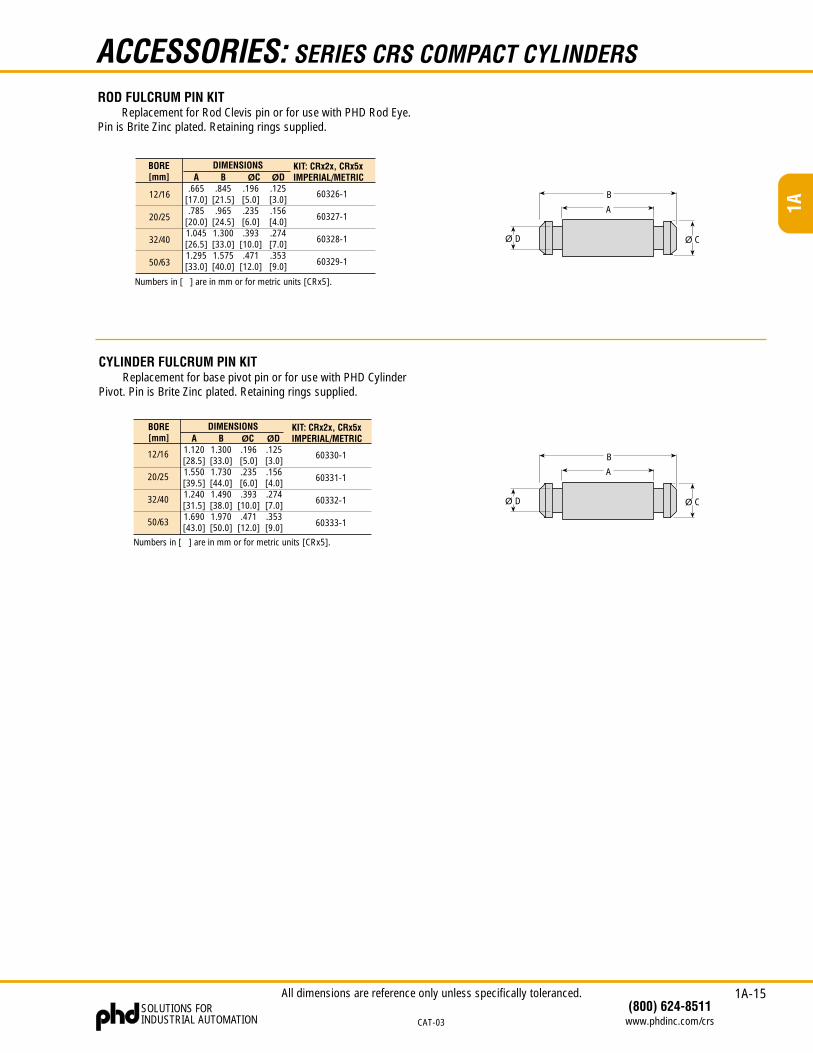
ROD FULCRUM PIN KITReplacement for Rod Clevis pin or for use with PHD Rod Eye.
Pin is Brite Zinc plated. Retaining rings supplied.
DIMENSIONS
Numbers in [ ] are in mm or for metric units [CRx5].
A.665
[17.0].785
[20.0]1.045[26.5]1.295[33.0]
B.845
[21.5].965
[24.5]1.300[33.0]1.575[40.0]
ØC.196[5.0].235[6.0].393
[10.0].471
[12.0]
KIT: CRx2x, CRx5xIMPERIAL/METRIC
60326-1
60327-1
60328-1
60329-1
12/16
20/25
32/40
50/63
BORE[mm] ØD
.125[3.0].156[4.0].274[7.0].353[9.0]
A
B
Ø CØ D
CYLINDER FULCRUM PIN KITReplacement for base pivot pin or for use with PHD Cylinder
Pivot. Pin is Brite Zinc plated. Retaining rings supplied.
DIMENSIONS
Numbers in [ ] are in mm or for metric units [CRx5].
BORE[mm] A
1.120[28.5]1.550[39.5]1.240[31.5]1.690[43.0]
B1.300[33.0]1.730[44.0]1.490[38.0]1.970[50.0]
ØC.196[5.0].235[6.0].393
[10.0].471
[12.0]
KIT: CRx2x, CRx5xIMPERIAL/METRIC
60330-1
60331-1
60332-1
60333-1
12/16
20/25
32/40
50/63
ØD.125[3.0].156[4.0].274[7.0].353[9.0]
A
B
Ø CØ D
All dimensions are reference only unless specifically toleranced.
1A-16
1A
SOLUTIONS FORINDUSTRIAL AUTOMATION
(800) 624-8511www.phdinc.com/crs CAT-03
APPLICATIONS: SERIES CRS COMPACT CYLINDERS
EXTENSION
UNATTACHEDLOAD
UNATTACHEDLOAD
RETRACTIONSHOCK PADS
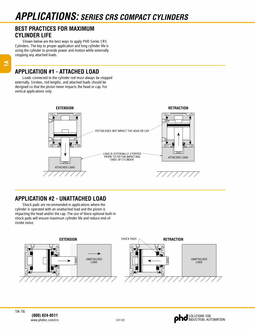
BEST PRACTICES FOR MAXIMUMCYLINDER LIFE
Shown below are the best ways to apply PHD Series CRSCylinders. The key to proper application and long cylinder life isusing the cylinder to provide power and motion while externallystopping any attached loads.
EXTENSION RETRACTION
LOAD IS EXTERNALLY STOPPEDPRIOR TO PISTON IMPACTING
ENDS OF CYLINDER
PISTON DOES NOT IMPACT THE HEAD OR CAP
ATTACHED LOAD
ATTACHED LOAD
APPLICATION #1 - ATTACHED LOADLoads connected to the cylinder rod must always be stopped
externally. Strokes, rod lengths, and attached loads should bedesigned so that the piston never impacts the head or cap. Forvertical applications only.
APPLICATION #2 - UNATTACHED LOADShock pads are recommended in applications where the
cylinder is operated with an unattached load and the piston isimpacting the head and/or the cap. The use of these optional built-inshock pads will ensure maximum cylinder life and reduce end-of-stroke noise.