Embed Size (px)
Citation preview

Single Auger Packer
Model APO
Operation and Maintenance Manual

2205 Jothi Avenue Parsons, Kansas 67357-8460
Toll Free: 888.882.9567
Phone: 620.421.5550 Fax: 620.421.5531
Web: www.magnumsystems.com Email: [email protected]
Machine Serial Number: Sales Order Number:

Revision 005 i Model APO
Single Auger Packer – Open Mouth Bag
Important Information
Conventions Safety Alert Symbols The symbol indicates that important personal safety information follows. Carefully read this text for the warnings information it contains. The signal word next to each safety alert symbol is defined as:
WARNING Indicates a potentially hazardous situation that, if not avoided, could result in death or serious injury.
CAUTION Indicates a potentially hazardous situation that, if not avoided, may result in minor or moderate injury, or damage to the equipment. This single word may also be used to identify unsafe practices.
LOCKOUT This symbol will be used anytime that a procedure requires an
electrical lockout.
Static Sensitive Symbols for Equipment Handling Instructions The and symbols indicate important handling guidelines for proper handling of electronic equipment modules and sensitive components for the prevention of potential damage that could be caused by ESD (electrostatic discharge) during routine maintenance, handling and transportation.
ESD NOTICE
To protect against ESD damage to electronic equipment, follow the Standard ESD Prevention Procedures. Failure to use protective measures could result in permanent equipment damage, either immediate or latent, when handling modules.
ESD NOTICE
To protect against ESD damage to electronic equipment containing components, follow the Standard ESD Prevention Procedures. Failure to use recommended protective measures could result in permanent equipment damage, either immediate or latent, when handling components.

Model APO
Single Auger Packer – Open Mouth Bag ii Revision 005
Standard Electro-static Discharge (ESD) Prevention Procedures The Model APO Single Auger Packer utilizes many electronic components that are susceptible to damage from Electro Static Discharge. Anytime electronic components are serviced, the following precautions should be followed:
1. Wear a commercial grounding wrist strap. 2. Remove power from the machine. 3. Leave all static sensitive components in their protective packaging until it is time to install the
component 4. Always hold static sensitive components by their metal mounting tabs, and/or by their edges
Important/Notable Information While all of the information in this manual is important, there are some pieces of information where special attention needs to be paid to avoid equipment damage, or specific information needs to be emphasized. This information will be handled as follows:
Important: Indicates an operating procedure, practice, or condition that, if not strictly followed, may cause equipment damage.
Note: Indicates additional information or emphasizes a topic related to the subject being discussed.
Personal Safety Instructions Only qualified personnel should work on or around this equipment. To ensure the highest degree of personal safety, all who use this equipment are required to become thoroughly familiar with all safety instructions contained in this document. Successful and safe operation of this equipment depends upon proper handling, operation, maintenance, and application of associated equipment. Refer to Appendix A of this manual for all safety instructions. Safety instructions are also provided where they apply within the body of this manual.
WARNING No information in this manual supersedes or replaces your employer’s operating rules. If there is a difference in instructions between this manual and the employer’s operating rules, follow the most restrictive instruction.
Deliberate misuse or abuse of electronic components may cause personal injury or death.
Revision 005 iii Model APO
Single Auger Packer – Open Mouth Bag
Warranty Information Seller warrants that the Products will operate substantially in conformance with Seller's published specifications, when subjected to normal, proper and intended usage by properly trained personnel, for a period of one (1) year from the date of shipment to Buyer (the "Warranty Period"). Seller agrees during the Warranty Period, provided it is promptly notified in writing upon the discovery of any defect and further provided that all costs of returning the defective Products to Seller are pre-paid by Buyer, to repair or replace, at Seller's option, defective Products so as to cause the same to operate in substantial conformance with said specifications. Replacement parts may be new or refurbished, at the election of Seller. All replaced parts shall become the property of Seller. Replacement Parts will be billed at list price, unless they are approved as warranty replacement item(s) by the service technician and the technical services manager.
Lamps, fuses, bulbs and other expendable items are expressly excluded from the warranty. Seller's sole liability with respect to equipment, materials, parts or software furnished to Seller by third party suppliers shall be limited to the assignment by Seller to Buyer of any such third party supplier's warranty, to the extent the same is assignable. In no event shall Seller have any obligation to make repairs, replacements or corrections required, in whole or in part, as the result of (i) normal wear and tear, (ii) accident, disaster or event of force majeure, (iii) misuse, fault or negligence of or by Buyer, (iv) use of the Products in a manner for which they were not designed, (v) causes external to the Products such as, but not limited to, power failure or electrical power surges, (vi) improper storage of the Products or (vii) use of the Products in combination with equipment or software not supplied by Seller. If Seller determines that Products for which Buyer has requested warranty services are not covered by the warranty hereunder, Buyer shall pay or reimburse Seller for all costs of investigating and responding to such request at Seller's then prevailing time and materials rates. If Seller provides repair services or replacement parts that are not covered by the warranty, the Buyer shall pay Seller therefore at Seller's then prevailing time and materials rates. ANY INSTALLATION, MAINTENANCE, REPAIR, SERVICE, RELOCATION OR ALTERATION TO OR OF, OR OTHER TAMPERING WITH, THE PRODUCTS PERFORMED BY ANY PERSON OR ENTITY OTHER THAN SELLER WITHOUT SELLER'S PRIOR WRITTEN APPROVAL, OR ANY USE OF REPLACEMENT PARTS NOT SUPPLIED BY SELLER, SHALL IMMEDIATELY VOID AND CANCEL ALL WARRANTIES WITH RESPECT TO THE AFFECTED PRODUCTS.
Field Service Magnum Systems can provide field service for start-up assistance, training, and maintenance of on new and existing equipment. Contact Magnum Systems at (888) 882-9567.
Model APO
Single Auger Packer – Open Mouth Bag iv Revision 005
This Page Intentionally Left Blank
Revision 005 v Model APO
Single Auger Packer – Open Mouth Bag
APO Single Auger Packer – Open Mouth Bag Table of Contents
Chapter Page 1 Product Description ................................................................................................... 1-1
1.1 General Description ..................................................................................................................... 1-1 1.2 Introduction .................................................................................................................................. 1-1 1.3 Manual Scope ............................................................................................................................... 1-1 1.4 Electrical Requirements ............................................................................................................... 1-1 1.5 Pneumatic Requirements .............................................................................................................. 1-1 1.6 Major Systems and Components .................................................................................................. 1-2
1.6.1 Base Frame ......................................................................................................................................... 1-2 1.6.2 Load Cell ............................................................................................................................................ 1-3 1.6.3 Weigh Mast ........................................................................................................................................ 1-3 1.6.4 Open Mouth Bag Spout ...................................................................................................................... 1-4 1.6.5 Blow Out Switch ................................................................................................................................ 1-4 1.6.6 Inflatable Neck Seal Pressure Switch ................................................................................................. 1-4 1.6.7 Drive Motor ........................................................................................................................................ 1-4 1.6.8 Rear Cover .......................................................................................................................................... 1-5 1.6.9 Flex Leaves ......................................................................................................................................... 1-5 1.6.10 Agitator ............................................................................................................................................. 1-5 1.6.11 Bag Settlers ....................................................................................................................................... 1-5 1.6.12 Auger Shaft Seals ............................................................................................................................. 1-6
1.6.12.1 Purge Seals ...............................................................................................................................................1-6 1.6.12.2 Felt Seals ..................................................................................................................................................1-7
1.6.13 Surge Hopper .................................................................................................................................... 1-7 1.6.14 Hopper .............................................................................................................................................. 1-7 1.6.15 Transition .......................................................................................................................................... 1-7 1.6.16 Dust Hood ......................................................................................................................................... 1-8 1.6.17 Machine Controls ............................................................................................................................. 1-9
1.6.17.1 Manual Controls and Indicators ................................................................................................................1-9 1.6.17.2 T4000 Controls ....................................................................................................................................... 1-10 1.6.17.3 T3000 Controls ....................................................................................................................................... 1-11 1.6.17.4 Allen-Bradley PanelView 300 ................................................................................................................ 1-13 1.6.17.5 Allen-Bradley Programmable Logic Controller (PLC) .......................................................................... 1-13
1.7 Power Control Box ..................................................................................................................... 1-14 1.8 Purge Kit .................................................................................................................................... 1-15
2 Receiving Equipment ................................................................................................. 2-1 2.1 General Description ..................................................................................................................... 2-1 2.2 Uncrating the Equipment ............................................................................................................. 2-1
3 Setup/Installation ....................................................................................................... 3-1 3.1 General Description ..................................................................................................................... 3-1 3.2 Making Electrical Connections .................................................................................................... 3-1 3.3 Making Pneumatic Connections .................................................................................................. 3-1 3.4 Mechanical Setup ......................................................................................................................... 3-1

Model APO
Single Auger Packer – Open Mouth Bag vi Revision 005
3.5 Making Network Connections ..................................................................................................... 3-2 3.5.1 DeviceNet Cabling ............................................................................................................................. 3-2 3.5.2 HardyLink Cabling ............................................................................................................................. 3-2 3.5.3 IR Port Cabling ................................................................................................................................... 3-2 3.5.4 RS-232 Simplex Serial Port Cabling .................................................................................................. 3-2 3.5.5 Remote I/O (RIO) Cabling (Optional) ................................................................................................ 3-2 3.5.6 ControlNet Cabling (Optional) ........................................................................................................... 3-2 3.5.7 Profibus I/O (Optional) ....................................................................................................................... 3-2 3.5.8 Modbus over TCP/IP (Optional) ........................................................................................................ 3-2 3.5.9 OLE Process Control (OPC) (Optional) ............................................................................................. 3-2
3.6 Establishing System Security Settings ......................................................................................... 3-3 3.6.1 T4000 Security Settings ...................................................................................................................... 3-3 3.6.2 T3000 Security Settings ...................................................................................................................... 3-6
3.7 Calibration .................................................................................................................................... 3-7 3.7.1 T4000 Control Panel ........................................................................................................................... 3-9
3.7.1.1 T4000 Pre-Calibration Procedures .............................................................................................................. 3-9 3.7.1.2 Calibrating The T4000 Control Panel ....................................................................................................... 3-10
3.7.2 Calibrating The T3000 Control Panel (Optional) ............................................................................. 3-13 4 Operation .................................................................................................................... 4-1
4.1 General Description ..................................................................................................................... 4-1 4.2 General Fill Cycle Information .................................................................................................... 4-1 4.3 Operational Controls .................................................................................................................... 4-2
4.3.1 T4000 Controls ................................................................................................................................... 4-2 4.3.1.1 Entering Numbers Using The T4000 Control Panel .................................................................................. 4-3 4.3.1.2 T4000 Single Set Point (SSP) Setup .......................................................................................................... 4-3 4.3.1.3 T4000 Dual Set Point (DSP) Setup ............................................................................................................ 4-3
4.3.2 T3000 Controls ................................................................................................................................... 4-4 4.3.3 Allen-Bradley MicroLogixTM 1000 .................................................................................................... 4-5 4.3.4 Allen-Bradley PanelView 300 ............................................................................................................ 4-6
4.3.4.1 PV300 Menus ............................................................................................................................................ 4-6 4.3.4.1.1 PV300 Menu Functions .......................................................................................................................... 4-7 4.3.4.2 Making System Adjustments With the PV300 Control Panel ................................................................. 4-10
4.4 Starting the Unit ......................................................................................................................... 4-11 4.4.1 T4000 Control Set ............................................................................................................................ 4-11 4.4.2 T3000 Control Set ............................................................................................................................ 4-12
4.5 Initial Setup ................................................................................................................................ 4-13 4.5.1 Setting Up a Single Set Point APO with T4000 Controls ................................................................ 4-13 4.5.2 Setting Up a Dual Set Point APO with T4000 Controls ................................................................... 4-15 4.5.3 Using the T3000 to Set Points and Feeder Speeds ........................................................................... 4-17
4.5.3.1 T3000 Single Set Point ............................................................................................................................ 4-17 4.5.3.2 T3000 Dual Set Point ............................................................................................................................... 4-18
5 Preventive Maintenance ............................................................................................ 5-1 5.1 General Description ..................................................................................................................... 5-1 5.2 Daily Maintenance Procedures .................................................................................................... 5-1
5.2.1 Cleaning .............................................................................................................................................. 5-1 5.2.2 Check Calibration ............................................................................................................................... 5-1 5.2.3 Drain Water From the Water Separator .............................................................................................. 5-1
5.3 Monthly Maintenance .................................................................................................................. 5-2 5.4 Purge Kit Maintenance ................................................................................................................. 5-2
Revision 005 vii Model APO
Single Auger Packer – Open Mouth Bag
6 Troubleshooting ......................................................................................................... 6-1 6.1 General Description ..................................................................................................................... 6-1 6.2 The Troubleshooting Process ....................................................................................................... 6-1 6.3 Trouble Symptoms ....................................................................................................................... 6-1
6.3.1 Machine Will Not Power On .............................................................................................................. 6-1 6.3.2 Machine Will Not Start When the Start Button is Pressed ................................................................. 6-2 6.3.3 Inflatable Neck Seal Will Not Inflate ................................................................................................. 6-2 6.3.4 Scale is Not Accurate ......................................................................................................................... 6-2 6.3.5 Scale Does Not Return to Zero ........................................................................................................... 6-3 6.3.6 The Weighments are Always Too Light ............................................................................................. 6-3
6.3.6.1 Fast Filling Products (Less Than 5 Seconds of Fill Time) .........................................................................6-3 6.3.6.2 Normal Filling Products (5 Seconds or More of Fill Time) .......................................................................6-3
6.3.7 The Weighments are Always Too Heavy ........................................................................................... 6-3 6.3.8 Load Cell Fails Frequently ................................................................................................................. 6-4 6.3.9 The Weighments Fluctuate Between Too Light and Too Heavy ....................................................... 6-4 6.3.10 APO Does Not Start After The START Button Is Pushed ............................................................... 6-4
6.4 System Alarms ............................................................................................................................. 6-5 6.4.1 T4000 Alarms ..................................................................................................................................... 6-5 6.4.2 T3000 Alarms ..................................................................................................................................... 6-6 6.4.3 PLC Error Messages ............................................................................................................................ 6-6
6.4.3.1 Status Messages ..........................................................................................................................................6-6 6.4.3.2 Reminder Messages ....................................................................................................................................6-6 6.4.3.3 Warning Messages ......................................................................................................................................6-6 6.4.3.4 Fault Messages ...........................................................................................................................................6-6
6.5 Purge Kit Troubleshooting ........................................................................................................... 6-6 7 Repair and Adjustment ............................................................................................. 7-1
7.1 General Description ..................................................................................................................... 7-1 7.2 System Adjustment Procedures ................................................................................................... 7-1
7.2.1 Air Pressure Adjustment ..................................................................................................................... 7-1 7.2.2 Purge Seal Adjustment/Calibration .................................................................................................... 7-2 7.2.3 Inflatable Neck Seal Pressure Switch Adjustment ............................................................................. 7-2 7.2.4 Blow Out Switch Adjustment ............................................................................................................. 7-3 7.2.5 Auger Shaft Seal Adjustment ............................................................................................................. 7-3 7.2.6 Timer Adjustments ............................................................................................................................. 7-3
7.3 Component Replacement Procedures .......................................................................................... 7-4 7.3.1 Spout Replacement ............................................................................................................................. 7-4
7.3.1.1 Spout Removal ...........................................................................................................................................7-4 7.3.1.2 Spout Installation ........................................................................................................................................7-5
7.3.2 Inflatable Neck Seal Replacement ...................................................................................................... 7-6 7.3.2.1 Inflatable Neck Seal Removal ....................................................................................................................7-6 7.3.2.2 Inflatable Neck Seal Installation .................................................................................................................7-8
7.3.3 Air Supply Line Replacement .......................................................................................................... 7-10 7.3.3.1 Air Supply Line Removal ......................................................................................................................... 7-10 7.3.3.2 Air Supply Line Installation ..................................................................................................................... 7-10
7.3.4 Air Fitting Replacement ................................................................................................................... 7-10 7.3.4.1 Air Fitting Removal .................................................................................................................................. 7-10 7.3.4.2 Air Fitting Installation .............................................................................................................................. 7-11
7.3.5 Air Filter/Regulator/Lubricator (FRL) Replacement ........................................................................ 7-11 7.3.5.1 FRL Assembly Removal .......................................................................................................................... 7-11 7.3.5.2 FRL Assembly Installation ....................................................................................................................... 7-11

Model APO
Single Auger Packer – Open Mouth Bag viii Revision 005
7.3.7 Flex Leaf Replacement ..................................................................................................................... 7-12 7.3.7.1 Flex Leaf Removal ................................................................................................................................... 7-12 7.3.7.2 Flex Leaf Installation ............................................................................................................................... 7-12
7.3.8 Drive Belt Replacement .................................................................................................................... 7-13 7.3.8.1 Drive Belt Removal ................................................................................................................................. 7-13 7.3.8.2 Drive Belt Installation .............................................................................................................................. 7-13
7.3.9 Purge Seal Replacement ................................................................................................................... 7-14 7.3.9.1 Purge Seal Removal ................................................................................................................................. 7-14 7.3.9.2 Purge Seal Installation ............................................................................................................................. 7-14
7.3.10 Auger Replacement (Used with Standard Auger Option) .............................................................. 7-16 7.3.10.1 Auger Removal (Standard Auger) ......................................................................................................... 7-16 7.3.10.2 Auger Installation (Standard Auger) ...................................................................................................... 7-16
7.3.11 Auger Replacement (Used with Replaceable Auger Option) ......................................................... 7-17 7.3.11.1 Auger Removal (Optional Removable Auger) ...................................................................................... 7-17 7.3.11.2 Auger Installation (Optional Removable Auger) ................................................................................... 7-17
7.3.12 Auger Shaft Bearing Replacement ................................................................................................. 7-18 7.3.12.1 Auger Shaft Bearing Removal ............................................................................................................... 7-18 7.3.12.2 Auger Shaft Bearing Installation ............................................................................................................ 7-18
7.3.13 Load Cell Replacement .................................................................................................................. 7-20 7.3.13.1 Load Cell Removal ................................................................................................................................ 7-20 7.3.13.2 Load Cell Installation ............................................................................................................................. 7-21
7.3.14 Agitator Replacement ..................................................................................................................... 7-21 7.3.14.1 Agitator Removal (Standard Belt Driven Agitator) ............................................................................... 7-21 7.3.14.2 Agitator Installation (Standard Belt Driven Agitator) ............................................................................ 7-21 7.3.14.3 Agitator Removal (Optional Electric Agitator) ...................................................................................... 7-23 7.3.14.4 Agitator Installation (Optional Electric Agitator) .................................................................................. 7-23
7.3.15 Flow Gate Replacement .................................................................................................................. 7-24 7.3.15.1 Flow Gate Removal ............................................................................................................................... 7-24 7.3.15.2 Flow Gate Installation ............................................................................................................................ 7-24
7.3.16 Flow Gate Hinge Replacement ....................................................................................................... 7-25 7.3.16.1 Flow Gate Hinge Removal ..................................................................................................................... 7-25 7.3.16.2 Flow Gate Hinge Installation ................................................................................................................. 7-25
7.3.17 Flow Gate Cylinder Replacement ................................................................................................... 7-26 7.3.17.1 Flow Gate Cylinder Removal ................................................................................................................ 7-26 7.3.17.2 Flow Gate Cylinder Installation ............................................................................................................. 7-26
7.3.18 Transition Replacement .................................................................................................................. 7-26 7.3.18.1 Transition Removal ................................................................................................................................ 7-26 7.3.18.2 Transition Installation ............................................................................................................................ 7-27
7.3.19 Dust Hood Replacement ................................................................................................................. 7-27 7.3.19.1 Dust Hood Removal ............................................................................................................................... 7-27 7.3.19.2 Dust Hood Installation ........................................................................................................................... 7-28
7.3.20 Blow Out Switch Replacement ....................................................................................................... 7-29 7.3.20.1 Blow Out Switch Removal .................................................................................................................... 7-29 7.3.20.2 Blow Out Switch Installation ................................................................................................................. 7-29
7.3.21 Vacuum Probe Replacement .......................................................................................................... 7-30 7.3.21.1 Vacuum Probe Removal ........................................................................................................................ 7-30 7.3.21.2 Vacuum Probe Installation ..................................................................................................................... 7-31
7.3.23 MAC Valve Replacement ............................................................................................................... 7-32 7.3.23.1 MAC Valve Removal ............................................................................................................................ 7-32 7.3.23.2 MAC Valve Installation ......................................................................................................................... 7-32
7.3.24 Auger Shaft Seal Replacement ....................................................................................................... 7-33 7.3.24.1 Auger Shaft Seal Removal ..................................................................................................................... 7-33 7.3.24.2 Auger Shaft Seal Installation ................................................................................................................. 7-33
Revision 005 ix Model APO
Single Auger Packer – Open Mouth Bag
Glossary .............................................................................................................. Glossary-1 Index ......................................................................................................................... Index-1 Appendix A Safety Procedures ..................................................................................... A-1 Appendix B Spare Parts ................................................................................................ B-1 Appendix C Mechanical Drawings ............................................................................... C-1 Appendix D Electrical Drawings .................................................................................. D-1 Appendix E T3000 Control Panel User Guide ............................................................ E-1 Appendix F Custom Features ....................................................................................... F-1

Model APO
Single Auger Packer – Open Mouth Bag x Revision 005
This Page Intentionally Left Blank
Revision 005 xi Model APO
Single Auger Packer – Open Mouth Bag
List of Figures
Figure Page Figure 1-1. Major Components (Left-Front View) ................................................................................. 1-2 Figure 1-2. Load Cell .............................................................................................................................. 1-3 Figure 1-3. Weigh Mast .......................................................................................................................... 1-3 Figure 1-4. Open mouth bag spout ......................................................................................................... 1-4 Figure 1-5. Blow Out Switch .................................................................................................................. 1-4 Figure 1-6. Upper Flex Leaf (Top Left Shown) ..................................................................................... 1-5 Figure 1-7. Lower Flex Leaves ............................................................................................................... 1-5 Figure 1-8. Purge Seal Cross Section ..................................................................................................... 1-6 Figure 1-9. Purge Seal............................................................................................................................. 1-6 Figure 1-10. Felt Auger Shaft Seal, Exploded View .............................................................................. 1-7 Figure 1-11. Transition and Dust Hood .................................................................................................. 1-8 Figure 1-12. T4000 Control Panel ........................................................................................................ 1-10 Figure 1-13. T3000 Control Panel ........................................................................................................ 1-11 Figure 1-14. Sample T3000 Control Box ............................................................................................. 1-12 Figure 1-15. Allen-Bradley PanelView 300 ......................................................................................... 1-13 Figure 1-16. Allen-Bradley MicroLogixTM 1000 Programmable Logic Controller ............................... 1-13 Figure 1-17. Power Control Box ........................................................................................................... 1-14 Figure 1-18. Purge Kit .......................................................................................................................... 1-15 Figure 2-1. Typical Shell Crate ............................................................................................................... 2-1 Figure 2-2. Shipping Bracket (1 of 4 shown) ......................................................................................... 2-2 Figure 3-1. Placing The Cursor In Front Of Security ............................................................................. 3-3 Figure 3-2. Placing The Cursor In Front Of Set Password ..................................................................... 3-3 Figure 3-3. Set Password Menu .............................................................................................................. 3-4 Figure 3-4. Password Set To 123 ............................................................................................................ 3-4 Figure 3-5. Verify Password ................................................................................................................... 3-4 Figure 3-6. SECUR Menu Item Shown Above Function Key................................................................ 3-5 Figure 3-7. Parameter Shown Locked .................................................................................................... 3-5 Figure 3-8. Hanging a Certified Test Weight ......................................................................................... 3-8 Figure 3-9. Load Passing Through Load Cell ......................................................................................... 3-9 Figure 3-10. Placing the Cursor In Front Of Calibration ...................................................................... 3-10 Figure 3-11. Placing The Cursor In Front Of Trad Cal ........................................................................ 3-11 Figure 3-12. Placing The Cursor In Front Of Zero Value .................................................................... 3-11 Figure 3-13. Span Value Displayed ...................................................................................................... 3-12 Figure 3-14. Calibration Type Screen (TRAD selected) ...................................................................... 3-14 Figure 3-15. Do Trad. Cal (Zero) .......................................................................................................... 3-14 Figure 3-16. Do Trad. Cal (Span) ......................................................................................................... 3-14 Figure 4-1. Bulk Rate vs. Dribble Rate ................................................................................................... 4-1 Figure 4-2. T4000 Features ..................................................................................................................... 4-2 Figure 4-3. T3000 Control Panel ............................................................................................................ 4-4 Figure 4-4. Allen-Bradley MicroLogixTM 1000 Programmable Logic Controller ................................... 4-5 Figure 4-5. Allen-Bradley PanelView 300 ............................................................................................. 4-6 Figure 4-6. Turning an APO with T4000 Control Set On .................................................................... 4-11
Model APO
Single Auger Packer – Open Mouth Bag xii Revision 005
Figure 4-7. Turning an APO with T3000 Control Set On .................................................................... 4-12 Figure 4-8. APO ON/OFF Switch ........................................................................................................ 4-13 Figure 4-9. Initial Setup – Single Set Point APO ................................................................................. 4-14 Figure 4-10. SP1 Adjustment Screen .................................................................................................... 4-14 Figure 4-11. APO ON/OFF Switch ...................................................................................................... 4-15 Figure 4-12. Setting the Dribble Weight (SP1) .................................................................................... 4-15 Figure 4-13. SP1 Adjustment Screen .................................................................................................... 4-16 Figure 4-14. Setting the Target Weight (SP2) ...................................................................................... 4-16 Figure 4-15. SP2 Adjustment Screen .................................................................................................... 4-16 Figure 5-1. Air Supply Line Water Separator ......................................................................................... 5-2 Figure 7-1. Air Filter/Regulator/Lubricator ............................................................................................ 7-1 Figure 7-2. Inflatable Neck Seal Pressure Switch Adjustment ............................................................... 7-2 Figure 7-3. Open Mouth Bag Spout Mount ............................................................................................ 7-4 Figure 7-4. APO Spout and Associated Components, Exploded View .................................................. 7-5 Figure 7-5. Sectional View of Spout and Inflatable Bladder .................................................................. 7-6 Figure 7-6. Applying Pressure to Compression Ring Tabs, Using C-Clamp Locking Pliers ................. 7-7 Figure 7-7. Creating the Flap .................................................................................................................. 7-8 Figure 7-8. Creating the Upper Flap ....................................................................................................... 7-9 Figure 7-9. Air Supply Fitting .............................................................................................................. 7-11 Figure 7-10. Flex Leaves – Exploded View ......................................................................................... 7-12 Figure 7-11. Belt Tension Adjustment.................................................................................................. 7-13 Figure 7-12. Sliding the Purge Seal on the Shaft .................................................................................. 7-14 Figure 7-13. Setting the Purge Pressure ................................................................................................ 7-15 Figure 7-14. Checking the Seal for Square ........................................................................................... 7-15 Figure 7-15. Bearing Mounting Position .............................................................................................. 7-18 Figure 7-16. Bearing Setscrews, 180° Out-Of-Phase ........................................................................... 7-19 Figure 7-17. Load Cell Mounting ......................................................................................................... 7-20 Figure 7-18. Standard Belt Driven Agitator, Exploded View .............................................................. 7-22 Figure 7-19. Optional Electric Agitator Assembly, Exploded View .................................................... 7-23 Figure 7-20. Flow Gate Components, Exploded View ......................................................................... 7-24 Figure 7-21. Flow Gate Hinge .............................................................................................................. 7-25 Figure 7-22. Transition Mounting......................................................................................................... 7-27 Figure 7-23. Mounting The Dust Hood On The Transition .................................................................. 7-28 Figure 7-24. Blow Out Switch Mounting ............................................................................................. 7-29 Figure 7-25. MAC Valve (Solenoid Removed) .................................................................................... 7-32 Figure 7-26. Auger Shaft Seal, Exploded View ................................................................................... 7-33
Revision 005 xiii Model APO
Single Auger Packer – Open Mouth Bag
List of Tables
Table Page Table 1-1. Allen-Bradley MicroLogixTM PLC LED Definitions ............................................................. 4-5 Table 4-2. PV300 Main Menu ................................................................................................................ 4-7 Table 4-3. PV300 Set BD Timers Menu ................................................................................................. 4-8 Table 4-4. PV300 Counters Menu .......................................................................................................... 4-8 Table 4-5. PV300 Settler Menu .............................................................................................................. 4-8 Table 4-6. PV300 Probe Purge Menu ..................................................................................................... 4-9 Table 4-7. PV300 Thumper Menu .......................................................................................................... 4-9 Table 4-8. System Adjustments Example ............................................................................................. 4-10 Table 4-9. Example – Adjusting the Variable ...................................................................................... 4-10 Table B-1. APO Spare Parts List ........................................................................................................... B-1 Table C-1. APO Mechanical Drawing List ............................................................................................ C-1 Table D-1. APO Electrical Drawing List ............................................................................................... D-1

Model APO
Single Auger Packer – Open Mouth Bag xiv Revision 005
This Page Intentionally Left Blank

General Description
Revision 005 1-1 Model APO
Single Auger Packer – Open Mouth Bag
Chapter 1 Product Description
1.1 General Description This chapter will provide a high-level product description of the APO Single Auger Packer.
1.2 Introduction The Magnum Systems Model APO is an electronic auger packer. The APO may be equipped with either a T4000 control panel or a T3000 control panel. The APO is configured to fill open mouth bags.
1.3 Manual Scope This manual will provide information on installation, operation, preventive maintenance, troubleshooting, adjustment, and repair of the Model APO.
The appendices will include safety information, spare parts list, mechanical drawings, electrical drawings, the T4000/T4000A Operation and Maintenance Manual or the T3000 Quick Reference Guide (if equipped), and the Pressurization/Purging System Installation & Operation Manual (if equipped).
1.4 Electrical Requirements The APO requires two distinctly different voltages for proper operation. The control circuits operate on 115 VAC/60 Hz./20 Amp circuit. The feed and drive circuits operate on 230 or 460 VAC 3 phase/60 Hz. power.
Depending on the configuration, there may be one or two electrical connections. The standard configuration uses separate electrical connections for the control circuits and the feed/drive circuits.
1.5 Pneumatic Requirements The Model APO uses approximately 3-15 CFM (57-85 liters) @ 80-100 PSI (.55-.69 MPa) of compressed air. Magnum Systems recommends that the air supply line be equipped with a refrigerated air dryer, or at the very least a water separator.

General Description
Model APO
Single Auger Packer – Open Mouth Bag 1-2 Revision 005
1.6 Major Systems and Components When working with the Model APO, it is important to understand the major systems and components of the unit. The breakdown is as follows:
Figure 1-1. Major Components (Left-Front View)
1.6.1 Base Frame The base frame is the backbone of the APO. It provides a support structure for the all of the other components that make up the APO.
Spout
Rear cover
Inflatable neck seal
Surge hopper
Drive motor
Base frame
Vacuum probe (optional)
Weigh mast
Hopper
Rear electrical enclosure
Adjustable platform
Transition
Vacuum pump (optional)
Dust hood
Blow out switch
Load cell
General Description
Revision 005 1-3 Model APO
Single Auger Packer – Open Mouth Bag
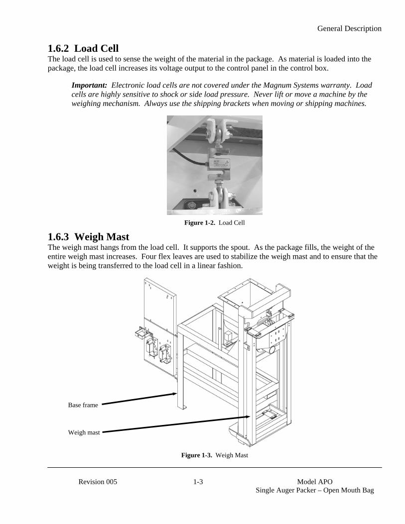
1.6.2 Load Cell The load cell is used to sense the weight of the material in the package. As material is loaded into the package, the load cell increases its voltage output to the control panel in the control box.
Important: Electronic load cells are not covered under the Magnum Systems warranty. Load cells are highly sensitive to shock or side load pressure. Never lift or move a machine by the weighing mechanism. Always use the shipping brackets when moving or shipping machines.
Figure 1-2. Load Cell
1.6.3 Weigh Mast The weigh mast hangs from the load cell. It supports the spout. As the package fills, the weight of the entire weigh mast increases. Four flex leaves are used to stabilize the weigh mast and to ensure that the weight is being transferred to the load cell in a linear fashion.
Figure 1-3. Weigh Mast
Base frame
Weigh mast

General Description
Model APO
Single Auger Packer – Open Mouth Bag 1-4 Revision 005
1.6.4 Open Mouth Bag Spout An open mouth bag spout with an inflatable neck seal is used on the APO. The neck seal prevents leakage of the product and any dust from exiting through the gap between the spout and package.
Figure 1-4. Open mouth bag spout
1.6.5 Blow Out Switch A blow out switch, mounted on the rear of the spout, prevents the neck seal from being over inflated. The switch is equipped with a wire bale that is attached to a rotary switch mechanism.
Figure 1-5. Blow Out Switch
1.6.6 Inflatable Neck Seal Pressure Switch The pressure switch for the inflatable neck seal is used to determine when sufficient pressure has been reached in the neck seal and the MAC valve can be closed to shut off the supply air to the neck seal.
1.6.7 Drive Motor A 230 or 460 VAC drive motor is used to drive the auger. The motor uses a dual v-belt drive system. The motor is mounted in the center of the base frame on a hinged mounting plate.
General Description
Revision 005 1-5 Model APO
Single Auger Packer – Open Mouth Bag
1.6.8 Rear Cover A sheet metal cover is used to enclose the drive belt system, the auger drive shaft, and the agitator drive system. The rear cover has a sheet metal panel that can be removed to access the components inside.
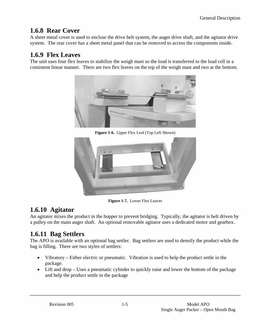
1.6.9 Flex Leaves The unit uses four flex leaves to stabilize the weigh mast so the load is transferred to the load cell in a consistent linear manner. There are two flex leaves on the top of the weigh mast and two at the bottom.
Figure 1-6. Upper Flex Leaf (Top Left Shown)
Figure 1-7. Lower Flex Leaves
1.6.10 Agitator An agitator mixes the product in the hopper to prevent bridging. Typically, the agitator is belt driven by a pulley on the main auger shaft. An optional removable agitator uses a dedicated motor and gearbox.
1.6.11 Bag Settlers The APO is available with an optional bag settler. Bag settlers are used to densify the product while the bag is filling. There are two styles of settlers:
• Vibratory – Either electric or pneumatic. Vibration is used to help the product settle in the package.
• Lift and drop – Uses a pneumatic cylinder to quickly raise and lower the bottom of the package and help the product settle in the package

General Description
Model APO
Single Auger Packer – Open Mouth Bag 1-6 Revision 005
1.6.12 Auger Shaft Seals The APO uses seals on the auger shafts to prevent product from leaking out of the hopper. The APO is available with two different types of auger shaft seals:
• Purge seals • Felt seals
1.6.12.1 Purge Seals The purge seals operate differently from most mechanical seals. They seal between two faces running perpendicular to the shaft. A rubber boot held in place with a hose clamp rotates with the shaft and drives two rotors against a stator plate. The purge seal is made up of the following components:
Rotating Elements A. Boot (Elastomer Gland) B. Hose Clamp C. Rotor Cup
Stationary Elements D. Spacer Block E. Stainless Plate
Figure 1-8. Purge Seal Cross Section
Figure 1-9. Purge Seal
General Description
Revision 005 1-7 Model APO
Single Auger Packer – Open Mouth Bag
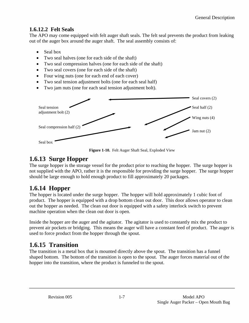
1.6.12.2 Felt Seals The APO may come equipped with felt auger shaft seals. The felt seal prevents the product from leaking out of the auger box around the auger shaft. The seal assembly consists of:
• Seal box • Two seal halves (one for each side of the shaft) • Two seal compression halves (one for each side of the shaft) • Two seal covers (one for each side of the shaft) • Four wing nuts (one for each end of each cover) • Two seal tension adjustment bolts (one for each seal half) • Two jam nuts (one for each seal tension adjustment bolt).
Figure 1-10. Felt Auger Shaft Seal, Exploded View
1.6.13 Surge Hopper The surge hopper is the storage vessel for the product prior to reaching the hopper. The surge hopper is not supplied with the APO, rather it is the responsible for providing the surge hopper. The surge hopper should be large enough to hold enough product to fill approximately 20 packages.
1.6.14 Hopper The hopper is located under the surge hopper. The hopper will hold approximately 1 cubic foot of product. The hopper is equipped with a drop bottom clean out door. This door allows operator to clean out the hopper as needed. The clean out door is equipped with a safety interlock switch to prevent machine operation when the clean out door is open.
Inside the hopper are the auger and the agitator. The agitator is used to constantly mix the product to prevent air pockets or bridging. This means the auger will have a constant feed of product. The auger is used to force product from the hopper through the spout.
1.6.15 Transition The transition is a metal box that is mounted directly above the spout. The transition has a funnel shaped bottom. The bottom of the transition is open to the spout. The auger forces material out of the hopper into the transition, where the product is funneled to the spout.
Seal box
Seal compression half (2)
Wing nuts (4)
Seal half (2)
Seal covers (2)
Seal tension adjustment bolt (2)
Jam nut (2)

General Description
Model APO
Single Auger Packer – Open Mouth Bag 1-8 Revision 005
1.6.16 Dust Hood The dust hood is mounted on top of the transition. The purpose of the hood is to contain product dust that is stirred up inside the transition. There is a dust port on top of the dust hood where a dust collection hose can be connected.
Figure 1-11. Transition and Dust Hood
Dust hood
Transition
General Description
Revision 005 1-9 Model APO
Single Auger Packer – Open Mouth Bag
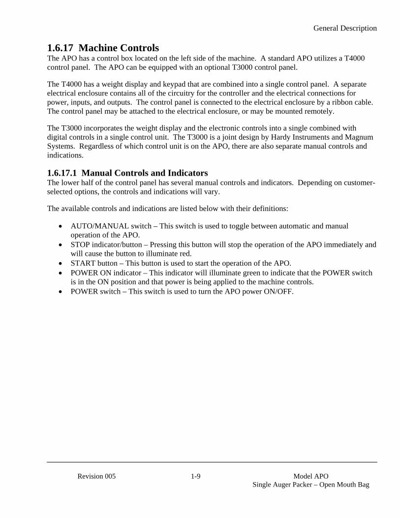
1.6.17 Machine Controls The APO has a control box located on the left side of the machine. A standard APO utilizes a T4000 control panel. The APO can be equipped with an optional T3000 control panel.
The T4000 has a weight display and keypad that are combined into a single control panel. A separate electrical enclosure contains all of the circuitry for the controller and the electrical connections for power, inputs, and outputs. The control panel is connected to the electrical enclosure by a ribbon cable. The control panel may be attached to the electrical enclosure, or may be mounted remotely.
The T3000 incorporates the weight display and the electronic controls into a single combined with digital controls in a single control unit. The T3000 is a joint design by Hardy Instruments and Magnum Systems. Regardless of which control unit is on the APO, there are also separate manual controls and indications.
1.6.17.1 Manual Controls and Indicators The lower half of the control panel has several manual controls and indicators. Depending on customer-selected options, the controls and indications will vary.
The available controls and indications are listed below with their definitions:
• AUTO/MANUAL switch – This switch is used to toggle between automatic and manual operation of the APO.
• STOP indicator/button – Pressing this button will stop the operation of the APO immediately and will cause the button to illuminate red.
• START button – This button is used to start the operation of the APO. • POWER ON indicator – This indicator will illuminate green to indicate that the POWER switch
is in the ON position and that power is being applied to the machine controls. • POWER switch – This switch is used to turn the APO power ON/OFF.

General Description
Model APO
Single Auger Packer – Open Mouth Bag 1-10 Revision 005
1.6.17.2 T4000 Controls A standard APO is equipped with a T4000 control panel. The T4000 control set uses different levels of voltage to monitor and control the weighments. The T4000 units are available in either single set point or dual set point models.
Item # Description Item # Description
1 Control Panel 5 Down arrow key2 Up arrow key 6 Left arrow key3 Enter key 7 Function keys4 Right arrow key 8 LCD screen
Figure 1-12. T4000 Control Panel

General Description
Revision 005 1-11 Model APO
Single Auger Packer – Open Mouth Bag
1.6.17.3 T3000 Controls The APO is available with an optional Taylor T3000 control set. This T3000 is a digital control panel that has been jointly designed by Magnum Systems and Hardy Instruments. The T3000 has the ability for total monitoring and instrument control. This control set allows the operator to monitor and control the APO. The T3000 features the following functions:
• Weight display • Alphanumeric keypad • Function keys • Enter/Exit keys • Arrow keys • Infrared (IR) Port (not used)
Figure 1-13. T3000 Control Panel
The front of the T3000 is equipped with a weight display, an alphanumeric keypad, directional arrow keys, function keys, an infrared PDA port (not used), an Enter key, and an Exit key.
The display has one line of large fonts (5.5 alphanumeric characters), and four lines of smaller fonts (20 alphanumeric characters). The top line displays the currently selected package weight. The remaining four lines are used for monitoring system statuses, historical data, and configuration settings of the APO.
Alphanumeric keypad
Enter/Exit keys
Weight display
Function keys
Infra Red PDA port (not used) Arrow keys
General Description
Model APO
Single Auger Packer – Open Mouth Bag 1-12 Revision 005
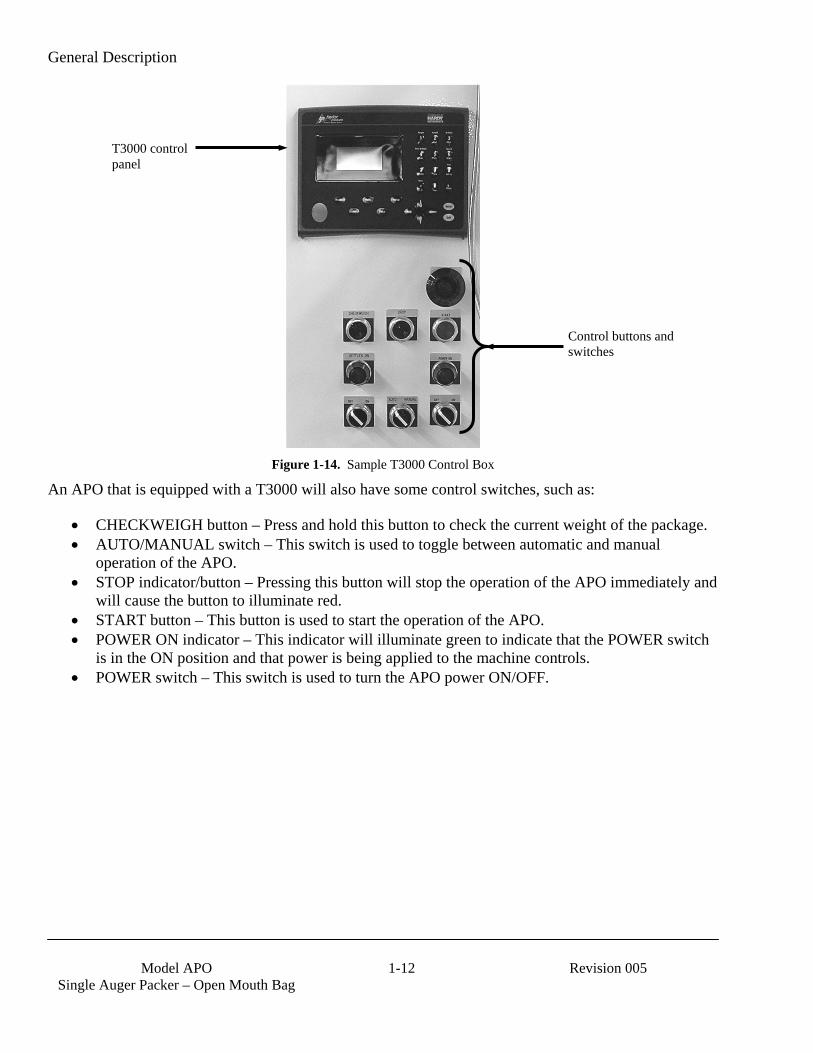
Figure 1-14. Sample T3000 Control Box
An APO that is equipped with a T3000 will also have some control switches, such as:
• CHECKWEIGH button – Press and hold this button to check the current weight of the package. • AUTO/MANUAL switch – This switch is used to toggle between automatic and manual
operation of the APO. • STOP indicator/button – Pressing this button will stop the operation of the APO immediately and
will cause the button to illuminate red. • START button – This button is used to start the operation of the APO. • POWER ON indicator – This indicator will illuminate green to indicate that the POWER switch
is in the ON position and that power is being applied to the machine controls. • POWER switch – This switch is used to turn the APO power ON/OFF.
T3000 control panel
Control buttons and switches
General Description
Revision 005 1-13 Model APO
Single Auger Packer – Open Mouth Bag
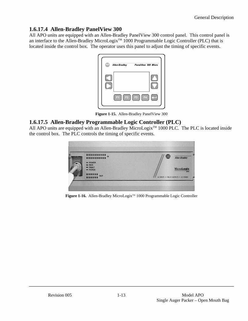
1.6.17.4 Allen-Bradley PanelView 300 All APO units are equipped with an Allen-Bradley PanelView 300 control panel. This control panel is an interface to the Allen-Bradley MicroLogixTM 1000 Programmable Logic Controller (PLC) that is located inside the control box. The operator uses this panel to adjust the timing of specific events.
Figure 1-15. Allen-Bradley PanelView 300
1.6.17.5 Allen-Bradley Programmable Logic Controller (PLC) All APO units are equipped with an Allen-Bradley MicroLogixTM 1000 PLC. The PLC is located inside the control box. The PLC controls the timing of specific events.
Figure 1-16. Allen-Bradley MicroLogixTM 1000 Programmable Logic Controller

General Description
Model APO
Single Auger Packer – Open Mouth Bag 1-14 Revision 005
1.7 Power Control Box The power control box is located on the rear of the APO. Inside this box are the following components:
• Allen-Bradley PowerFlex controller (optional) – Used for auger speed control and to start and stop the auger motor on APO units that are equipped as dual set point (DSP) machines.
• Fuses – Always check the electrical schematics for the specific machine that is being worked on. • Drive motor contactor – Driven by the power switch, this contactor is used to enable the
PowerFlex controller.
Figure 1-17. Power Control Box
AB PowerFlex controller – auger speed controller
Drive motor contactor
Fuses
General Description
Revision 005 1-15 Model APO
Single Auger Packer – Open Mouth Bag
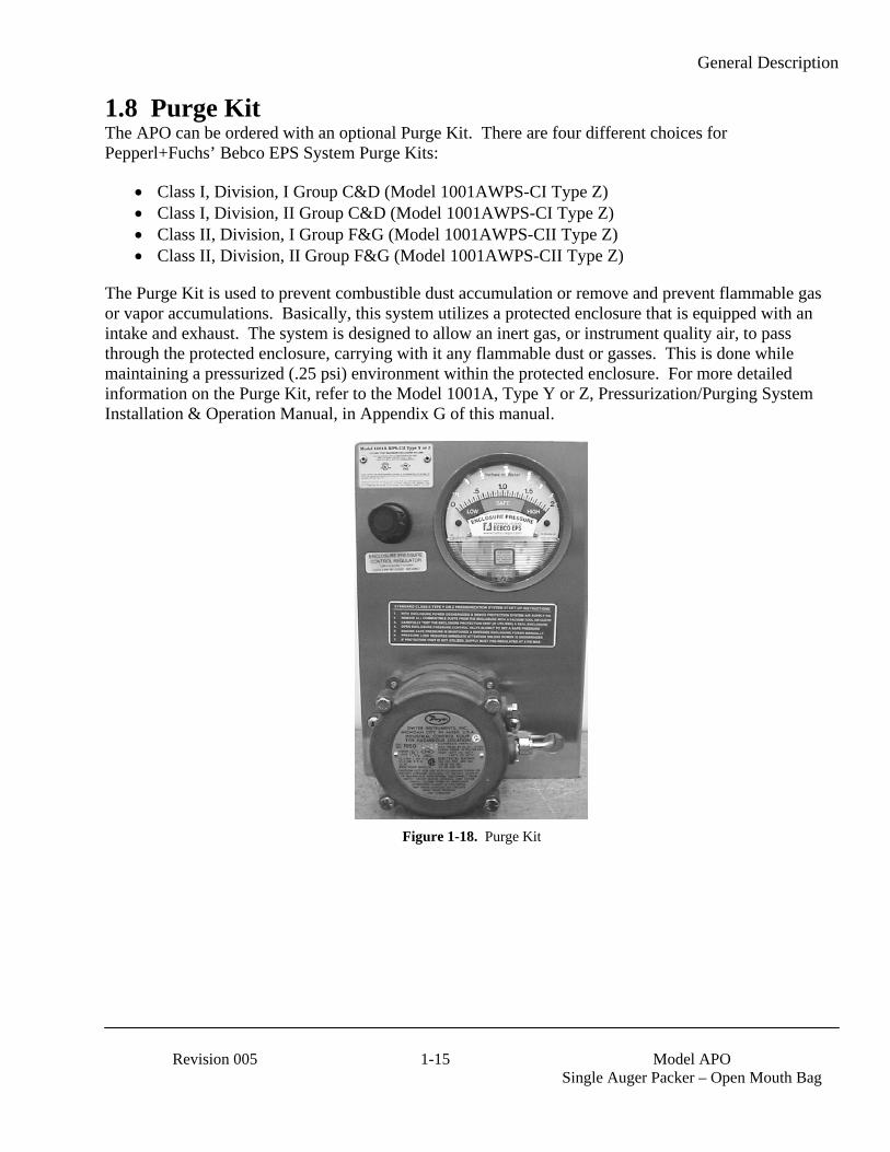
1.8 Purge Kit The APO can be ordered with an optional Purge Kit. There are four different choices for Pepperl+Fuchs’ Bebco EPS System Purge Kits:
• Class I, Division, I Group C&D (Model 1001AWPS-CI Type Z) • Class I, Division, II Group C&D (Model 1001AWPS-CI Type Z) • Class II, Division, I Group F&G (Model 1001AWPS-CII Type Z) • Class II, Division, II Group F&G (Model 1001AWPS-CII Type Z)
The Purge Kit is used to prevent combustible dust accumulation or remove and prevent flammable gas or vapor accumulations. Basically, this system utilizes a protected enclosure that is equipped with an intake and exhaust. The system is designed to allow an inert gas, or instrument quality air, to pass through the protected enclosure, carrying with it any flammable dust or gasses. This is done while maintaining a pressurized (.25 psi) environment within the protected enclosure. For more detailed information on the Purge Kit, refer to the Model 1001A, Type Y or Z, Pressurization/Purging System Installation & Operation Manual, in Appendix G of this manual.
Figure 1-18. Purge Kit

General Description
Model APO
Single Auger Packer – Open Mouth Bag 1-16 Revision 005
This Page Intentionally Left Blank
Receiving Equipment
Revision 005 2-1 Model APO
Single Auger Packer – Open Mouth Bag
Chapter 2 Receiving Equipment
2.1 General Description The APO and all of its components are thoroughly inspected before shipment. Upon receipt of the equipment, it is important that the machine be carefully inspected for shipping damage. In the event that damage is found, contact the shipping company and follow their process for reporting shipping damage.
2.2 Uncrating the Equipment Follow the procedure below to unpack the equipment and prepare it for installation.
1. The APO is a floor mount unit. Clear an area large enough for the machine and for a forklift to maneuver the machine into position. Make sure floor is level. It is recommended that the APO be located directly under the supply hopper. Complete any nearby construction before installing the APO.
2. Before opening the shell crate and removing APO from the shipping pallet, inspect the shell crate, pallet, and the APO for visible damage. Inspect for damaged or missing parts. If there is damage, notify the shipper and Magnum Systems immediately. If the unit is not damaged, proceed to the next step.
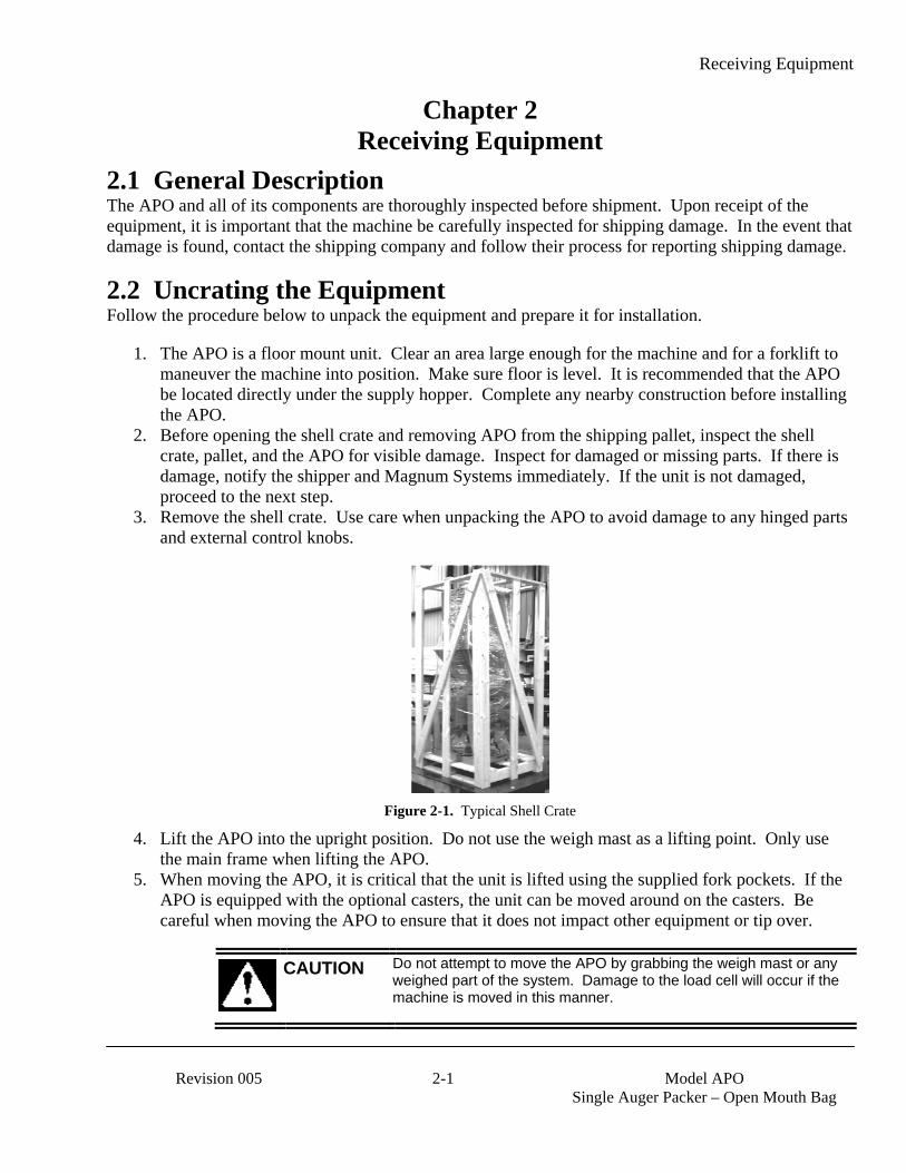
3. Remove the shell crate. Use care when unpacking the APO to avoid damage to any hinged parts and external control knobs.
Figure 2-1. Typical Shell Crate
4. Lift the APO into the upright position. Do not use the weigh mast as a lifting point. Only use the main frame when lifting the APO.
5. When moving the APO, it is critical that the unit is lifted using the supplied fork pockets. If the APO is equipped with the optional casters, the unit can be moved around on the casters. Be careful when moving the APO to ensure that it does not impact other equipment or tip over.
CAUTION Do not attempt to move the APO by grabbing the weigh mast or any weighed part of the system. Damage to the load cell will occur if the machine is moved in this manner.

Receiving Equipment
Model APO
Single Auger Packer – Open Mouth Bag 2-2 Revision 005
6. Once the APO is in its final position, remove the shipping brackets.
Figure 2-2. Shipping Bracket (1 of 4 shown)

Setup/Installation
Revision 005 3-1 Model APO
Single Auger Packer – Open Mouth Bag
Chapter 3 Setup/Installation
3.1 General Description Only persons who have been properly trained and hold the appropriate qualifications should attempt to install, operate, or maintain this equipment.
WARNING Before installing, adjusting, or servicing any electrical component, be sure to become familiar with the electrical schematic for the machine.
WARNING Before installing, adjusting, or servicing any pneumatic component, be sure to become familiar with the pneumatic schematic for the machine.
3.2 Making Electrical Connections Before connecting the APO to the electrical supply, it is vital that the unit be properly grounded. The recommended method is to plug the power cords into earth grounded receptacles.
The APO requires two separate power sources, one for the control circuits and one for the feed and drive circuits. The control circuits operate on a 115 VAC/60 Hz./20 Amp circuit. The drive and feed circuits can be configured to operate on either 230, or 460 VAC. The APO unit should be placed within 6 feet of the electrical outlets that it will be connected to.
3.3 Making Pneumatic Connections The APO requires a compressed air supply line that is capable of delivering approximately 3-15 CFM (57-85 liters) @ 80-100 PSI (.55-.69 MPa) of compressed air. Magnum Systems recommends that the air supply line be equipped with a refrigerated air dryer, or at the very least a water separator. After making pneumatic connections, check all connectors for leaks using a soapy water mixture. Bubbles will appear at the site of any leaks. Eliminating or reducing air leaks will reduce wear on the air supply equipment.
3.4 Mechanical Setup Once the APO has been moved into the position where it will operate, follow the steps below to setup the mechanical components for operation.
1. Use shims under the legs of the APO to ensure that the APO frame is level. If the frame is not level, the performance of the APO will be adversely affected.
2. Make sure the weigh mast is plumb and level. 3. Make sure the flex leaves are level. The flex leaves must not be angled downward or upward.
This would lead to inaccurate weighments. Adjust the angle of the flex leaves by adjusting how high or low the load cell allows the weigh mast to hang.
Setup/Installation
Model APO
Single Auger Packer – Open Mouth Bag 3-2 Revision 005
3.5 Making Network Connections APO units that are equipped with the optional digital control set have the ability for total monitoring and instrument control via the built in communication connectivity of the T3000. The T3000 has the following network capabilities:
• DeviceNet • HardyLink Ethernet • IR Port • RS-232 Simplex Serial Port • Remote I/O (RIO) (optional) • ControlNet (optional) • Profibus I/O (optional) • Modbus over TCP/IP (optional) • OLE Process Control (OPC) (optional)
3.5.1 DeviceNet Cabling DeviceNet utilizes special DeviceNet cable. This cable is a shielded 4-conductor cable.
3.5.2 HardyLink Cabling HardyLink utilizes standard Ethernet cable.
3.5.3 IR Port Cabling The IR Port does not require any cabling. Rather, it uses Infra Red technology for the transmission of data.
3.5.4 RS-232 Simplex Serial Port Cabling The RS-232 communications utilizes standard RS-232 serial cable.
3.5.5 Remote I/O (RIO) Cabling (Optional) The Remote I/O (RIO) communication functionality requires the use of Rockwell’s (Allen-Bradley) Blue Hose cable. This cable is a shielded 2-conductor cable.
3.5.6 ControlNet Cabling (Optional) ControlNet utilizes Rockwell’s (Allen-Bradley) ControlNet Cable.
3.5.7 Profibus I/O (Optional) Profibus I/O utilizes a 2-conductor cable with a 9-pin DIN connector.
3.5.8 Modbus over TCP/IP (Optional) Modbus over TCP/IP utilizes standard Ethernet cable.
3.5.9 OLE Process Control (OPC) (Optional) OLE Process Control utilizes standard Ethernet cable.
Setup/Installation
Revision 005 3-3 Model APO
Single Auger Packer – Open Mouth Bag
3.6 Establishing System Security Settings The manager has the ability to control who does and who does not have the ability to change system and calibration settings on all APO units.
3.6.1 T4000 Security Settings The Security parameters allow management to place security on the instrument and any menu or sub-menu requiring a password before enabling any changes. The Change Security parameter enables all persons to see the security status for a given menu, and selected persons to change that security status for any menu.
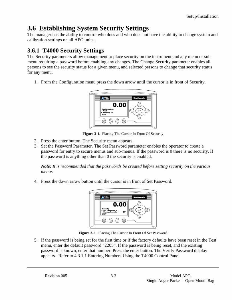
1. From the Configuration menu press the down arrow until the cursor is in front of Security.
Figure 3-1. Placing The Cursor In Front Of Security
2. Press the enter button. The Security menu appears. 3. Set the Password Parameter. The Set Password parameter enables the operator to create a
password for entry to secure menus and sub-menus. If the password is 0 there is no security. If the password is anything other than 0 the security is enabled.
Note: It is recommended that the passwords be created before setting security on the various menus.
4. Press the down arrow button until the cursor is in front of Set Password.
Figure 3-2. Placing The Cursor In Front Of Set Password
5. If the password is being set for the first time or if the factory defaults have been reset in the Test menu, enter the default password “2205”. If the password is being reset, and the existing password is known, enter that number. Press the enter button. The Verify Password display appears. Refer to 4.3.1.1 Entering Numbers Using the T4000 Control Panel.

Setup/Installation
Model APO
Single Auger Packer – Open Mouth Bag 3-4 Revision 005
6. Press the enter button. If the password is correct a brief message “Entry Accepted” appears and the Set Password display with the current password appears.
Figure 3-3. Set Password Menu
7. Press the function button located directly below the CLR item on the display to clear the entry. Use the left or right arrow buttons to move the cursor left and right. Use the up or down arrow buttons to enter the password number. To delete a single entry, press the left arrow button. In the example below, “123” was entered.
Figure 3-4. Password Set To 123
8. Press the right or left arrow buttons to toggle Change Security On. The Verify Password display appears.
Figure 3-5. Verify Password
9. Use the left or right arrow buttons to move the cursor left and right. Use the up or down arrow buttons to enter the password number. Important: When entering the password, the last digit is entered first, then the next digit to the left and so on. For example, if the password is set to 123, then 3 is entered first, then the 2, and the 1 is entered last.
Press this button to clear the current entry.
Press this button to save the entry.
Setup/Installation
Revision 005 3-5 Model APO
Single Auger Packer – Open Mouth Bag
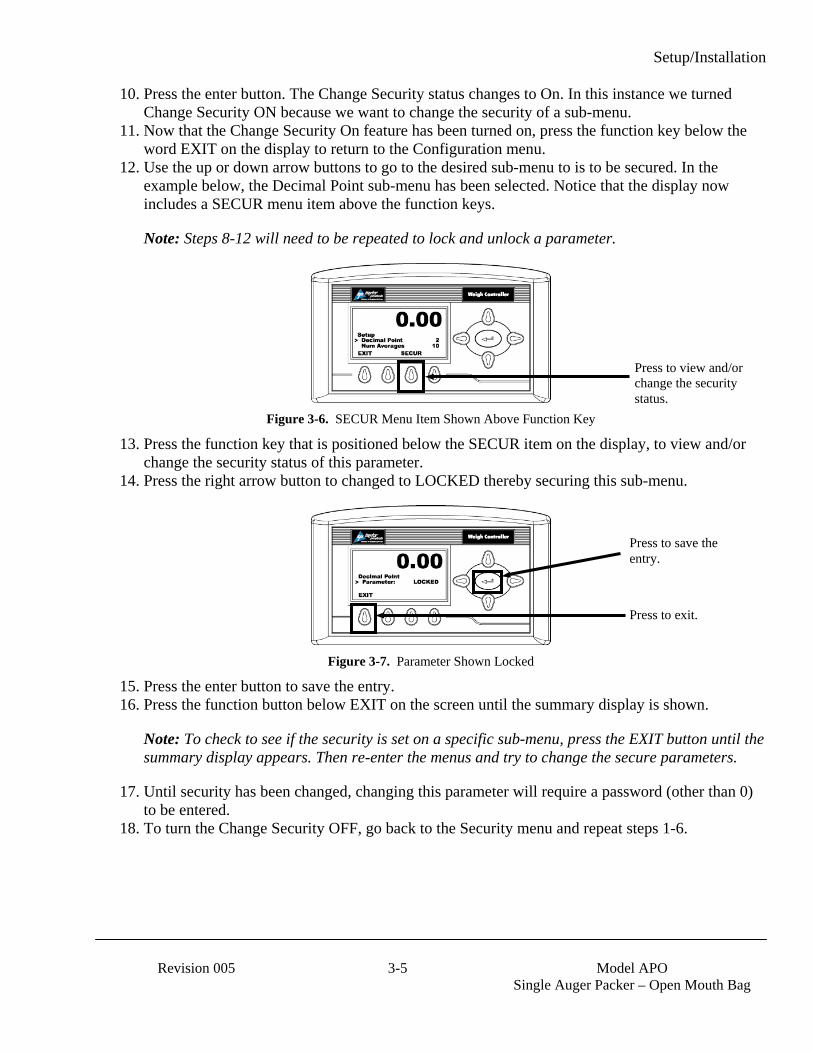
10. Press the enter button. The Change Security status changes to On. In this instance we turned Change Security ON because we want to change the security of a sub-menu.
11. Now that the Change Security On feature has been turned on, press the function key below the word EXIT on the display to return to the Configuration menu.
12. Use the up or down arrow buttons to go to the desired sub-menu to is to be secured. In the example below, the Decimal Point sub-menu has been selected. Notice that the display now includes a SECUR menu item above the function keys.
Note: Steps 8-12 will need to be repeated to lock and unlock a parameter.
Figure 3-6. SECUR Menu Item Shown Above Function Key
13. Press the function key that is positioned below the SECUR item on the display, to view and/or change the security status of this parameter.
14. Press the right arrow button to changed to LOCKED thereby securing this sub-menu.
Figure 3-7. Parameter Shown Locked
15. Press the enter button to save the entry. 16. Press the function button below EXIT on the screen until the summary display is shown.
Note: To check to see if the security is set on a specific sub-menu, press the EXIT button until the summary display appears. Then re-enter the menus and try to change the secure parameters.
17. Until security has been changed, changing this parameter will require a password (other than 0) to be entered.
18. To turn the Change Security OFF, go back to the Security menu and repeat steps 1-6.
Press to view and/or change the security status.
Press to save the entry.
Press to exit.
Setup/Installation
Model APO
Single Auger Packer – Open Mouth Bag 3-6 Revision 005
3.6.2 T3000 Security Settings There are three levels of system security on the T3000 control panel:
• Low – No password required. • Medium – A password is required to access some, but not all of the top level menus. The factory
preset password for this level of security is 7878. • High – A password is required to access all top-level menus. The factory preset password for
this level of security is 1232.
CAUTION DO NOT change the default passwords. If the default passwords are changed, and the new passwords are lost or forgotten, they cannot be recovered. A backdoor into the system does not exist. If this happens, the memory of the unit will have to be erased and a new program will have to be installed. All stored information, such as product definitions, will be lost.
Additionally, the manager also has the ability to assign different levels of security to individual menus. The menus where this applies are:
• Adjust Ingredient • Setup • Calibration • Options • I/O Mapping
If a menu has a Non-Low Security Level, when a user presses the Enter key to access the menu, the system display a !SECURITY VIOLATION! message. The user will need to backup to the Standby Display, and then press the User key to log in to the controller. If the user enters an invalid password or no password the user is given read access only to all sub-menus.
The T3000 will accept any 3-digit alphanumeric Operator ID that is entered. The T3000 will ask for a password after the user has signed in. The password is what determines the level of access. It is recommended that the manager create a list of individual Operator IDs. For the greatest level of control and for historical tracking purposes, Magnum Systems recommends that each person that has access to the menu systems be assigned their own unique ID. When changes are made to the configuration of the machine, or when a calibration occurs, the T3000 will log the time and date of those changes and the operator ID that was used when making the changes.
The manager should assign each operator ID either a High, Medium, or Low security clearance. Those operator IDs with High security level would be provided the High-level password. They can access all levels of the menu system. Those IDs with Medium security level would be provided the Medium-level password. They can access menus that have been assigned a Medium or Low security level. Those IDs with Low security level will not be assigned a password and can only access menus that have been assigned a Low security level.

Setup/Installation
Revision 005 3-7 Model APO
Single Auger Packer – Open Mouth Bag
Use the procedure below to assign security levels to the Top-Level menus.
Important: Only personnel who have been assigned the High-Level password have the ability to change the security level of a given menu.
1. Press the User shortcut key. 2. Use the keypad to enter the User ID. Press the Enter key to accept. 3. Use the keypad to enter the high-level password. Press the Enter key to accept. 4. The display will show a confirmation message indicating the security level that has been granted.
Make sure the security level displayed is the high-level. 5. From the Standby Display, press the Setup key. The CONFIGURATION MENU will appear. 6. Use the up or down arrow keys to move the cursor until it is positioned in front of the
SECURITY line. 7. Press the Enter key. The SECURITY MENU will appear. 8. Use the up or down arrow keys to move the cursor until it is positioned in front of the SET
SECURITY MENU line. 9. Press the Enter key. The SET SECURITY MENU will appear. All menus will be listed with
their current security level. The default level for most of the menus is Low. The exceptions are the Security Menu, the Application Type Menu, and the Factory Default Menu. These menus have a default security setting of High.
10. Use the up or down arrow keys to move the cursor until it is positioned in front of the menu that is going to be selected to have its security level changed.
11. Press the Left or Right arrow key to change the security level of the selected menu. 12. When the desired level of security is displayed for that menu, press the Enter key to store the
change. 13. Repeat steps 4 through 8 as needed until all Top-Level menus have the desired security settings. 14. Press the Exit key to return to the Standby Display.
3.7 Calibration Each APO is calibrated prior to leaving the factory. However, the unit should be reassessed before first use of the unit. It is recommended that the calibration of the unit should be checked every week or anytime that a new load cell or PC board is installed, a weight display conversion performed, or any other changes made that affect the weigh system. A certified test weight must be used to check the calibration of the APO.
Note: Make sure that the shipping brackets have been removed before beginning the calibration process.
During the calibration process, regardless of the type of control panel used, the operator will be asked to hang a certified test weight from the spout of the machine. Magnum Systems recommends that the certified test weight weigh approximately 80-100% of the intended package weight. Also, the test weight should be hung so it hangs under the center of the spout, as shown in the following graphic.
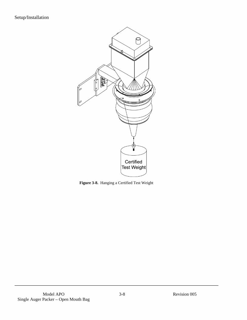
Setup/Installation
Model APO
Single Auger Packer – Open Mouth Bag 3-8 Revision 005
Figure 3-8. Hanging a Certified Test Weight
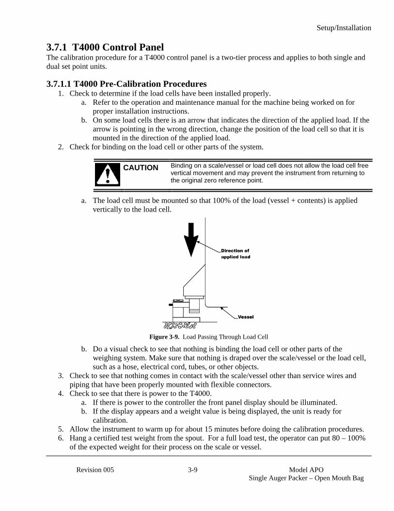
Setup/Installation
Revision 005 3-9 Model APO
Single Auger Packer – Open Mouth Bag
3.7.1 T4000 Control Panel The calibration procedure for a T4000 control panel is a two-tier process and applies to both single and dual set point units.
3.7.1.1 T4000 Pre-Calibration Procedures 1. Check to determine if the load cells have been installed properly.
a. Refer to the operation and maintenance manual for the machine being worked on for proper installation instructions.
b. On some load cells there is an arrow that indicates the direction of the applied load. If the arrow is pointing in the wrong direction, change the position of the load cell so that it is mounted in the direction of the applied load.
2. Check for binding on the load cell or other parts of the system.
CAUTION Binding on a scale/vessel or load cell does not allow the load cell free vertical movement and may prevent the instrument from returning to the original zero reference point.
a. The load cell must be mounted so that 100% of the load (vessel + contents) is applied vertically to the load cell.
Figure 3-9. Load Passing Through Load Cell
b. Do a visual check to see that nothing is binding the load cell or other parts of the weighing system. Make sure that nothing is draped over the scale/vessel or the load cell, such as a hose, electrical cord, tubes, or other objects.
3. Check to see that nothing comes in contact with the scale/vessel other than service wires and piping that have been properly mounted with flexible connectors.
4. Check to see that there is power to the T4000. a. If there is power to the controller the front panel display should be illuminated. b. If the display appears and a weight value is being displayed, the unit is ready for
calibration. 5. Allow the instrument to warm up for about 15 minutes before doing the calibration procedures. 6. Hang a certified test weight from the spout. For a full load test, the operator can put 80 – 100%
of the expected weight for their process on the scale or vessel.
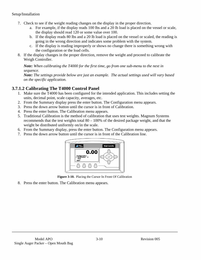
Setup/Installation
Model APO
Single Auger Packer – Open Mouth Bag 3-10 Revision 005
7. Check to see if the weight reading changes on the display in the proper direction. a. For example, if the display reads 100 lbs and a 20 lb load is placed on the vessel or scale,
the display should read 120 or some value over 100. b. If the display reads 80 lbs and a 20 lb load is placed on the vessel or scaled, the reading is
going in the wrong direction and indicates some problem with the system. c. If the display is reading improperly or shows no change there is something wrong with
the configuration or the load cells. 8. If the display changes in the proper direction, remove the weight and proceed to calibrate the
Weigh Controller. Note: When calibrating the T4000 for the first time, go from one sub-menu to the next in sequence. Note: The settings provide below are just an example. The actual settings used will vary based on the specific application.
3.7.1.2 Calibrating The T4000 Control Panel 1. Make sure the T4000 has been configured for the intended application. This includes setting the
units, decimal point, scale capacity, averages, etc. 2. From the Summary display press the enter button. The Configuration menu appears. 3. Press the down arrow button until the cursor is in front of Calibration. 4. Press the enter button. The Calibration menu appears. 5. Traditional Calibration is the method of calibration that uses test weights. Magnum Systems
recommends that the test weights total 80 – 100% of the desired package weight, and that the weight be distributed uniformly on/in the scale.
6. From the Summary display, press the enter button. The Configuration menu appears. 7. Press the down arrow button until the cursor is in front of the Calibration line.
Figure 3-10. Placing the Cursor In Front Of Calibration
8. Press the enter button. The Calibration menu appears.
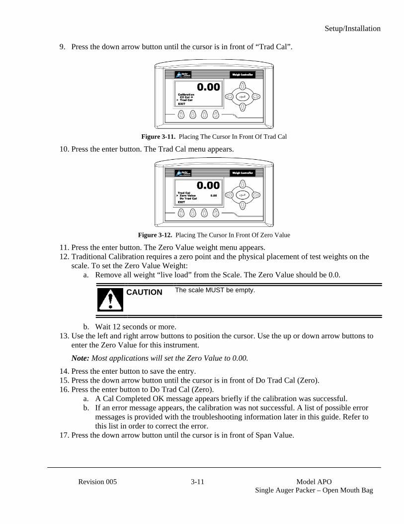
Setup/Installation
Revision 005 3-11 Model APO
Single Auger Packer – Open Mouth Bag
9. Press the down arrow button until the cursor is in front of “Trad Cal”.
Figure 3-11. Placing The Cursor In Front Of Trad Cal
10. Press the enter button. The Trad Cal menu appears.
Figure 3-12. Placing The Cursor In Front Of Zero Value
11. Press the enter button. The Zero Value weight menu appears. 12. Traditional Calibration requires a zero point and the physical placement of test weights on the
scale. To set the Zero Value Weight: a. Remove all weight “live load” from the Scale. The Zero Value should be 0.0.
CAUTION The scale MUST be empty.
b. Wait 12 seconds or more. 13. Use the left and right arrow buttons to position the cursor. Use the up or down arrow buttons to
enter the Zero Value for this instrument. Note: Most applications will set the Zero Value to 0.00.
14. Press the enter button to save the entry. 15. Press the down arrow button until the cursor is in front of Do Trad Cal (Zero). 16. Press the enter button to Do Trad Cal (Zero).
a. A Cal Completed OK message appears briefly if the calibration was successful. b. If an error message appears, the calibration was not successful. A list of possible error
messages is provided with the troubleshooting information later in this guide. Refer to this list in order to correct the error.
17. Press the down arrow button until the cursor is in front of Span Value.
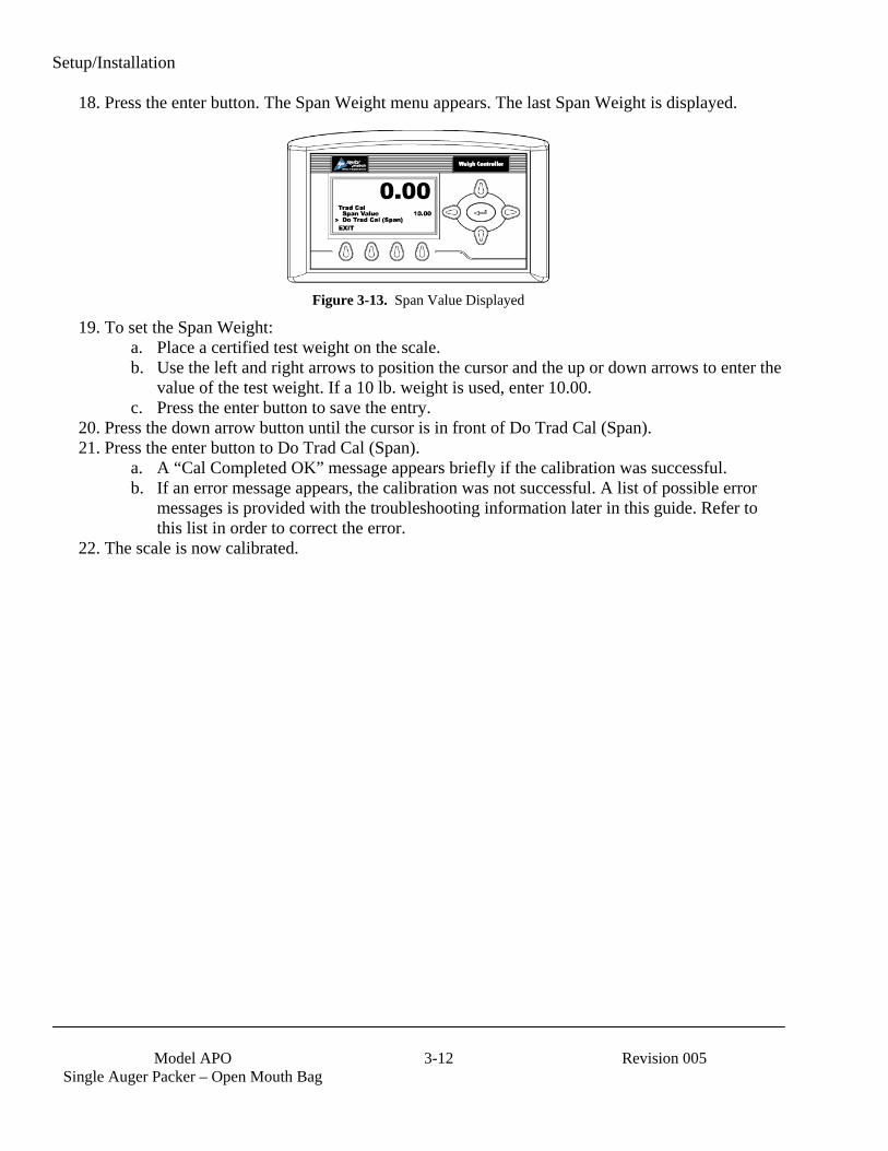
Setup/Installation
Model APO
Single Auger Packer – Open Mouth Bag 3-12 Revision 005
18. Press the enter button. The Span Weight menu appears. The last Span Weight is displayed.
Figure 3-13. Span Value Displayed
19. To set the Span Weight: a. Place a certified test weight on the scale. b. Use the left and right arrows to position the cursor and the up or down arrows to enter the
value of the test weight. If a 10 lb. weight is used, enter 10.00. c. Press the enter button to save the entry.
20. Press the down arrow button until the cursor is in front of Do Trad Cal (Span). 21. Press the enter button to Do Trad Cal (Span).
a. A “Cal Completed OK” message appears briefly if the calibration was successful. b. If an error message appears, the calibration was not successful. A list of possible error
messages is provided with the troubleshooting information later in this guide. Refer to this list in order to correct the error.
22. The scale is now calibrated.
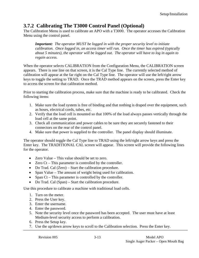
Setup/Installation
Revision 005 3-13 Model APO
Single Auger Packer – Open Mouth Bag
3.7.2 Calibrating The T3000 Control Panel (Optional) The Calibration Menu is used to calibrate an APO with a T3000. The operator accesses the Calibration Menu using the control panel.
Important: The operator MUST be logged in with the proper security level to initiate calibration. Once logged in, an access timer will run. Once the timer has expired (typically about 5 minutes), the operator will be logged out. The operator will have to log in again to regain access.
When the operator selects CALIBRATION from the Configuration Menu, the CALIBRATION screen appears. There is one line on that screen, it is the Cal Type line. The currently selected method of calibration will appear at the far right on the Cal Type line. The operator will use the left/right arrow keys to toggle the setting to TRAD. Once the TRAD method appears on the screen, press the Enter key to access the screen for that calibration method.
Prior to starting the calibration process, make sure that the machine is ready to be calibrated. Check the following items:
1. Make sure the load system is free of binding and that nothing is draped over the equipment, such as hoses, electrical cords, tubes, etc.
2. Verify that the load cell is mounted so that 100% of the load always passes vertically through the load cell at the same point.
3. Check all communication and power cables to be sure they are securely fastened to their connectors on the rear of the control panel.
4. Make sure that power is supplied to the controller. The panel display should illuminate.
The operator should toggle the Cal Type line to TRAD using the left/right arrow keys and press the Enter key. The TRADITIONAL CAL screen will appear. This screen will provide the following lines for the operator.
• Zero Value – This value should be set to zero. • Zero Ct – This parameter is controlled by the controller. • Do Trad. Cal (Zero) – Start the calibration procedure. • Span Value – The amount of weight being used for calibration. • Span Ct – This parameter is controlled by the controller. • Do Trad. Cal (Span) – Start the calibration procedure.
Use this procedure to calibrate a machine with traditional load cells. 1. Turn on the meter. 2. Press the User key. 3. Enter the username. 4. Enter the password. 5. Note the security level once the password has been accepted. The user must have at least
Medium-level security access to perform a calibration. 6. Press the Setup key. 7. Use the up/down arrow keys to scroll to the Calibration selection. Press the Enter key.
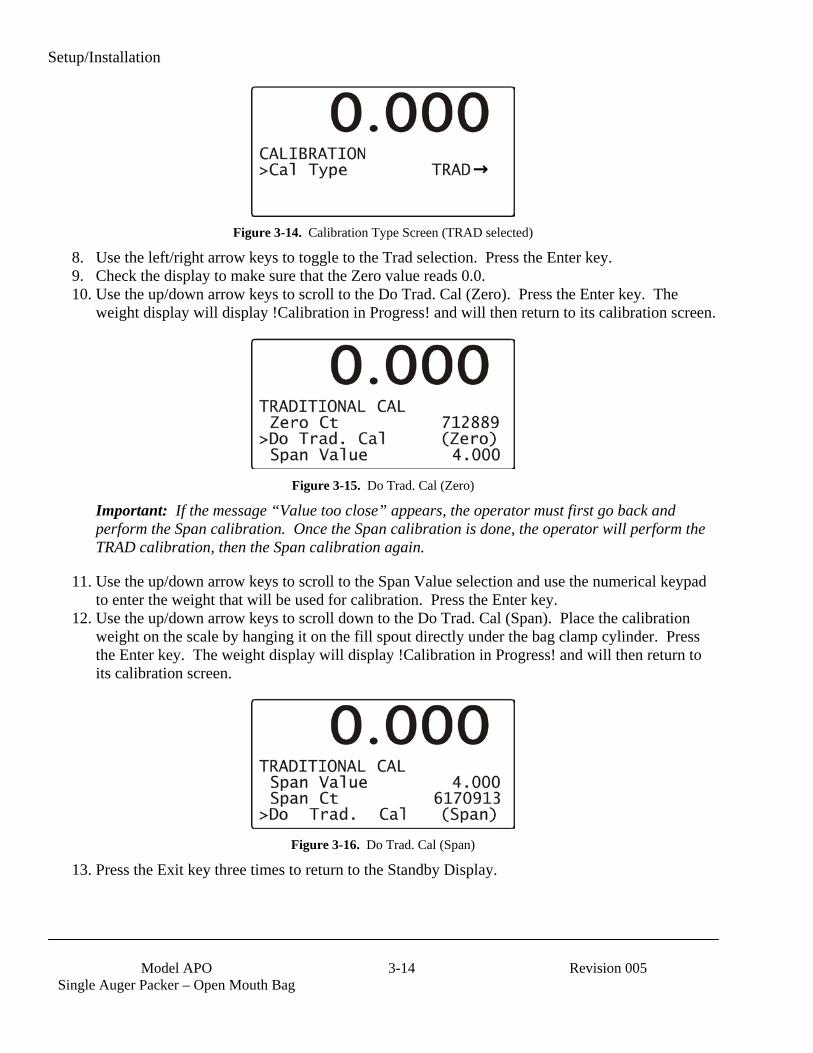
Setup/Installation
Model APO
Single Auger Packer – Open Mouth Bag 3-14 Revision 005
Figure 3-14. Calibration Type Screen (TRAD selected)
8. Use the left/right arrow keys to toggle to the Trad selection. Press the Enter key. 9. Check the display to make sure that the Zero value reads 0.0. 10. Use the up/down arrow keys to scroll to the Do Trad. Cal (Zero). Press the Enter key. The
weight display will display !Calibration in Progress! and will then return to its calibration screen.
Figure 3-15. Do Trad. Cal (Zero)
Important: If the message “Value too close” appears, the operator must first go back and perform the Span calibration. Once the Span calibration is done, the operator will perform the TRAD calibration, then the Span calibration again.
11. Use the up/down arrow keys to scroll to the Span Value selection and use the numerical keypad to enter the weight that will be used for calibration. Press the Enter key.
12. Use the up/down arrow keys to scroll down to the Do Trad. Cal (Span). Place the calibration weight on the scale by hanging it on the fill spout directly under the bag clamp cylinder. Press the Enter key. The weight display will display !Calibration in Progress! and will then return to its calibration screen.
Figure 3-16. Do Trad. Cal (Span)
13. Press the Exit key three times to return to the Standby Display.

Operation
Revision 005 4-1 Model APO
Single Auger Packer – Open Mouth Bag
Chapter 4 Operation
4.1 General Description This chapter will provide detailed descriptions of the operational controls of the APO.
4.2 General Fill Cycle Information A single set point unit has one fill rate. The package is filled using one fill rate (bulk rate) until the SP1 weight is reached, then the auger will stop and reverse momentarily to draw product away from the spout opening. Once the product that is in free fall settles into the package, the package weight should match the target weight.
A dual set point unit has two fill rates, bulk rate and dribble rate. Bulk rate is a faster rate that is used to fill the package quickly, once the package achieves the SP1 weight, the fill rate will slow to the dribble rate. Once the package achieves the SP2 weight, the auger will stop and reverse momentarily to draw product away from the spout opening, to prevent product from spilling out of the spout while the auger is stopped. Once the product that is in free fall settles into the package, the package weight should match the target weight.
Figure 4-1. Bulk Rate vs. Dribble Rate

Operation
Model APO
Single Auger Packer – Open Mouth Bag 4-2 Revision 005
4.3 Operational Controls The standard APO is equipped with T4000 controls. Optionally, the APO can be ordered with a T3000 controls. The setup procedure varies, based on the controls used. Use the following instructions to setup each type of controls.
Typically, the APO will be configured as a dual set point machine. However, some applications may use a single set point configuration. The following pages contain information on how to configure the machine for either configuration.
4.3.1 T4000 Controls The APO comes standard with T4000 controls and configured as a single set point unit. An option is available with the T4000 controls that will allow dual set points to increase operational efficiency.
The front of the T4000 is equipped with a weight display, directional arrow keys, function keys, and an Enter key.
Item # Description Item # Description
1 T4000 control panel 5 Down key2 Up key 6 Left key3 Right key 7 Function keys4 Enter key 8 LCD screen
Figure 4-2. T4000 Features
The 5-line display has one line of large fonts (5.5 alphanumeric characters), and four lines of smaller fonts (20 alphanumeric characters). The top line displays the currently selected package weight. The remaining four lines are used for monitoring system statuses, historical data, and configuration settings of the APO. The T4000 will show alarms. If alarms are present, refer to the Magnum Systems Model T4000/T4000A Weigh Controller, Operation and Maintenance Manual, for more information.
Operation
Revision 005 4-3 Model APO
Single Auger Packer – Open Mouth Bag
4.3.1.1 Entering Numbers Using The T4000 Control Panel Before using the control panel, it is important to understand the process for entering a number into a field. When accessing a numbered field, the cursor will be placed in the default position, which is under the digit to the far right. To position the cursor at the desired position, use the left/right arrow keys to move the cursor. Once the cursor is placed in the desired position, use the up arrow key to increase the number, or use the down arrow key to decrease the number. Each press of the key will result in a change increment of one digit. For example, if 0 is displayed, pressing the up arrow key once will change the number to 1. After the desired number has been entered, press the enter key to save the entry.
4.3.1.2 T4000 Single Set Point (SSP) Setup A single set point configuration uses only one fill rate. The machine will fill the package at the bulk rate until Set Point 2 (SP2) weight is achieved. SP2 is set just below the target weight. Once SP2 achieved, the auger will reverse momentarily to draw product away from the spout opening. This is done to reduce spillage when the package is removed from the spout. The reverse rate is the same rate as the forward speed. When SP2 is reached, there is still a small amount of product that is in free fall. This means that the product is falling from the spout into the package, so its weight has not yet registered. Once the free fall product settles in the package, the total weight of the package should match the target weight. Speed controls are not used on single set point APO units.
4.3.1.3 T4000 Dual Set Point (DSP) Setup A dual set point configuration uses two fill rates. The machine will fill the package at the Fast A rate until SP1 weight is achieved. SP1 is set at approximately 90% of the target weight. Once SP1 achieved, the auger speed will slow to the Slow A rate. SP2 is set just below the target weight. Once the SP2 weight is achieved, the auger will reverse momentarily to draw product away from the spout opening. This is done to reduce spillage when the package is removed from the spout. The reverse rate is the same rate as the forward Slow A speed. There is still a small amount of product that is in free fall. This means that the product is falling from the spout into the package, so its weight has not yet registered. Once the product in free fall settles in the package, the total weight of the package should match the target weight.

Operation
Model APO
Single Auger Packer – Open Mouth Bag 4-4 Revision 005
4.3.2 T3000 Controls This option utilizes a T3000 control panel that was jointly designed by Magnum Systems and Hardy Instruments.
Figure 4-3. T3000 Control Panel
The front of the T3000 is equipped with a weight display, a numeric keypad, directional arrow keys, function keys, an Infra Red PDA port (not used), an Enter key, and an Exit key.
The 5-line display has one line of large fonts (5.5 alphanumeric characters), and four lines of smaller fonts (20 alphanumeric characters). The top line displays the currently selected package weight. The remaining four lines are used for monitoring system statuses, historical data, and configuration settings of the APO. The T3000 will show alarms. If alarms are present, refer to the Magnum Systems Filler/Dispenser/IBC T3000 User Guide, for more information.
Alphanumeric keypad
Enter/Exit keys
Weight display
Function keys
Infra Red PDA port (not used) Arrow keys

Operation
Revision 005 4-5 Model APO
Single Auger Packer – Open Mouth Bag
4.3.3 Allen-Bradley MicroLogixTM 1000 All APO units are equipped with an Allen-Bradley MicroLogixTM 1000 Programmable Logic Controller (PLC). The PLC is located inside the control box. The PLC is loaded at the factory with a software program that includes adjustable timers for specific functions.
The PLC is equipped with several LEDs to provide status information to the user/operator.
Table 1-1. Allen-Bradley MicroLogixTM PLC LED Definitions
LED Definition POWER Illuminates (green) when power is being applied to the PLC. When power is not present the LED will be off. RUN This LED will illuminate to indicate that the PLC is operating and is not experiencing any fault conditions. FAULT This LED will illuminate to indicate the presence of a fault condition. When no faults are present, this LED
will be off. FORCE This LED will illuminate, along with a specific input or output LED, to indicate that the input or output has
been manually energized using an external programming tool. This is done to test individual inputs and outputs. To be able to perform this function, a properly equipped computer or handheld device must be connected to the PLC.
IN The PLC is equipped with 20 input LEDs, one for each AC input. If an input is energized (the PLC is receiving voltage on that channel), the LED will illuminate (green). If the input is not energized, the LED will be off.
OUT The PLC is equipped with 10 output LEDs, one for each relay output. If an output is energized (the PLC is supplying voltage to an external component through that channel), the LED will be illuminated (green). If the output is not energized, the corresponding LED will be off.
Figure 4-4. Allen-Bradley MicroLogixTM 1000 Programmable Logic Controller
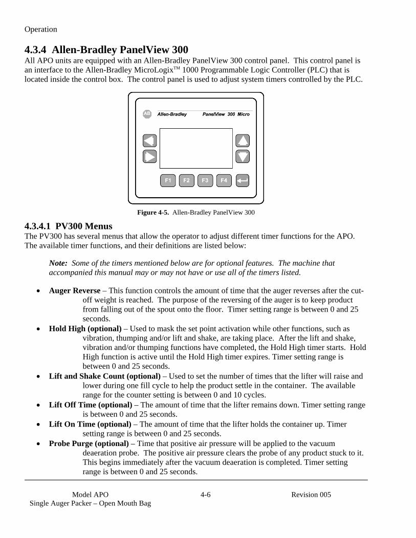
Operation
Model APO
Single Auger Packer – Open Mouth Bag 4-6 Revision 005
4.3.4 Allen-Bradley PanelView 300 All APO units are equipped with an Allen-Bradley PanelView 300 control panel. This control panel is an interface to the Allen-Bradley MicroLogixTM 1000 Programmable Logic Controller (PLC) that is located inside the control box. The control panel is used to adjust system timers controlled by the PLC.
Figure 4-5. Allen-Bradley PanelView 300
4.3.4.1 PV300 Menus The PV300 has several menus that allow the operator to adjust different timer functions for the APO. The available timer functions, and their definitions are listed below:
Note: Some of the timers mentioned below are for optional features. The machine that accompanied this manual may or may not have or use all of the timers listed.
• Auger Reverse – This function controls the amount of time that the auger reverses after the cut-off weight is reached. The purpose of the reversing of the auger is to keep product from falling out of the spout onto the floor. Timer setting range is between 0 and 25 seconds.
• Hold High (optional) – Used to mask the set point activation while other functions, such as vibration, thumping and/or lift and shake, are taking place. After the lift and shake, vibration and/or thumping functions have completed, the Hold High timer starts. Hold High function is active until the Hold High timer expires. Timer setting range is between 0 and 25 seconds.
• Lift and Shake Count (optional) – Used to set the number of times that the lifter will raise and lower during one fill cycle to help the product settle in the container. The available range for the counter setting is between 0 and 10 cycles.
• Lift Off Time (optional) – The amount of time that the lifter remains down. Timer setting range is between 0 and 25 seconds.
• Lift On Time (optional) – The amount of time that the lifter holds the container up. Timer setting range is between 0 and 25 seconds.
• Probe Purge (optional) – Time that positive air pressure will be applied to the vacuum deaeration probe. The positive air pressure clears the probe of any product stuck to it. This begins immediately after the vacuum deaeration is completed. Timer setting range is between 0 and 25 seconds.

Operation
Revision 005 4-7 Model APO
Single Auger Packer – Open Mouth Bag
• Settler Start Delay (optional) – Controls the amount of delay after the fill is started before the settler function begins. This delay allows functions that take place at the beginning of the fill to operate properly (i.e. Auto-Tare, Motion, etc.). Timer setting range is between 0 and 25 seconds.
• Settler Time (optional) – The amount of time that the settler function will remain active once initiated. The settler will run until either the settler timer has expired, or until SP1 is reached.
• Thumper Counter (optional) – Used to set the number of times that the thumper will activate to settle the product in the container during a fill cycle. The available range for the counter setting is between 0 and 10 cycles.
• Thumper Off Time (optional) – The amount of time that the thumper retracts and remains open between thumps. Timer setting range is between 0 and 25 seconds.
• Thumper On Time (optional) – The amount of time that the thumper will remain pushing in on the container. Timer setting range is between 0 and 25 seconds.
The tables on the following pages provide some examples of possible menu screens. The menu screens used on individual machines will vary. This manual does not show all of the available menu screens, as some customers may order custom menus.
4.3.4.1.1 PV300 Menu Functions The operator can access the PV300 menus and view/update system settings, using the F-keys and the up/down arrow keys. The tables below will illustrate the menus and describe the function of each applicable keystroke.
Table 4-2. PV300 Main Menu
Key Function
Pressing F1 will allow the operator to access the Set BD Timers menu.
Pressing F2 will allow the operator to access the Set Settler Timers menu.

Operation
Model APO
Single Auger Packer – Open Mouth Bag 4-8 Revision 005
Table 4-3. PV300 Set BD Timers Menu
Key Function
Pressing F1 will result in the system placing the cursor in the field where the Auger Reverse timer can be adjusted.
Pressing F2 will result in the system placing the cursor in the field where the Hold High timer can be adjusted.
Pressing F3 will result in the system advancing to the next menu screen.
Pressing F4 will result in the system returning to the Main Menu screen.
Table 4-4. PV300 Counters Menu
Key Function
Pressing F1 will result in the system placing the cursor in the field where the Lift & Shake Counter can be reset.
Pressing F3 will result in the system returning to the previous screen.
Pressing F4 will result in the system returning to the Main Menu.
Table 4-5. PV300 Settler Menu
Key Function
Pressing F1 will result in the system placing the cursor in the field where the timer for Lift On Time can be adjusted.
Pressing F2 will result in the system placing the cursor in the field where the timer for Lift Off Time can be adjusted.
Pressing F3 will result in the system proceeding to the next screen.
Pressing F4 will result in the system returning to the Main Menu.
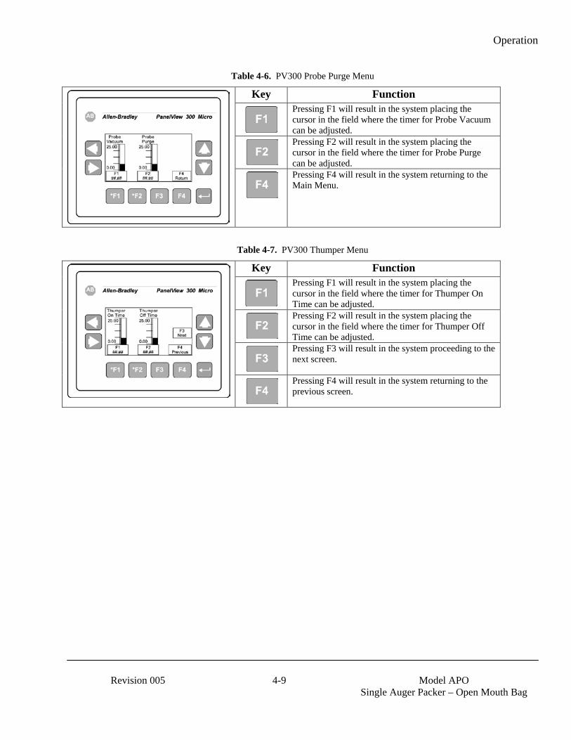
Operation
Revision 005 4-9 Model APO
Single Auger Packer – Open Mouth Bag
Table 4-6. PV300 Probe Purge Menu
Key Function
Pressing F1 will result in the system placing the cursor in the field where the timer for Probe Vacuum can be adjusted.
Pressing F2 will result in the system placing the cursor in the field where the timer for Probe Purge can be adjusted.
Pressing F4 will result in the system returning to the Main Menu.
Table 4-7. PV300 Thumper Menu
Key Function
Pressing F1 will result in the system placing the cursor in the field where the timer for Thumper On Time can be adjusted.
Pressing F2 will result in the system placing the cursor in the field where the timer for Thumper Off Time can be adjusted.
Pressing F3 will result in the system proceeding to the next screen.
Pressing F4 will result in the system returning to the previous screen.
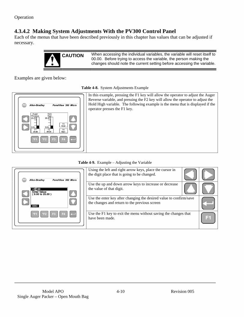
Operation
Model APO
Single Auger Packer – Open Mouth Bag 4-10 Revision 005
4.3.4.2 Making System Adjustments With the PV300 Control Panel Each of the menus that have been described previously in this chapter has values that can be adjusted if necessary.
CAUTION When accessing the individual variables, the variable will reset itself to 00.00. Before trying to access the variable, the person making the changes should note the current setting before accessing the variable.
Examples are given below:
Table 4-8. System Adjustments Example
In this example, pressing the F1 key will allow the operator to adjust the Auger Reverse variable, and pressing the F2 key will allow the operator to adjust the Hold High variable. The following example is the menu that is displayed if the operator presses the F1 key.
Table 4-9. Example – Adjusting the Variable
Using the left and right arrow keys, place the cursor in the digit place that is going to be changed.
Use the up and down arrow keys to increase or decrease the value of that digit.
Use the enter key after changing the desired value to confirm/save the changes and return to the previous screen
Use the F1 key to exit the menu without saving the changes that have been made.
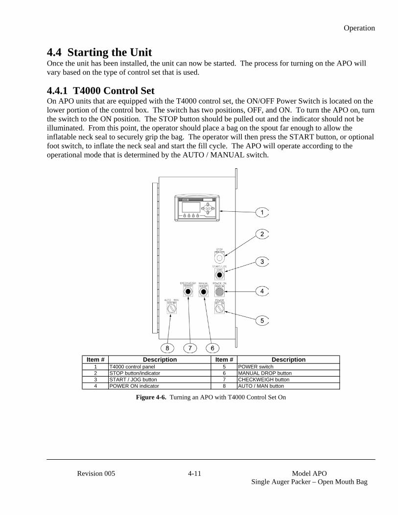
Operation
Revision 005 4-11 Model APO
Single Auger Packer – Open Mouth Bag
4.4 Starting the Unit Once the unit has been installed, the unit can now be started. The process for turning on the APO will vary based on the type of control set that is used.
4.4.1 T4000 Control Set On APO units that are equipped with the T4000 control set, the ON/OFF Power Switch is located on the lower portion of the control box. The switch has two positions, OFF, and ON. To turn the APO on, turn the switch to the ON position. The STOP button should be pulled out and the indicator should not be illuminated. From this point, the operator should place a bag on the spout far enough to allow the inflatable neck seal to securely grip the bag. The operator will then press the START button, or optional foot switch, to inflate the neck seal and start the fill cycle. The APO will operate according to the operational mode that is determined by the AUTO / MANUAL switch.
Item # Description Item # Description
1 T4000 control panel 5 POWER switch2 STOP button/indicator 6 MANUAL DROP button3 START / JOG button 7 CHECKWEIGH button4 POWER ON indicator 8 AUTO / MAN button
Figure 4-6. Turning an APO with T4000 Control Set On

Operation
Model APO
Single Auger Packer – Open Mouth Bag 4-12 Revision 005
4.4.2 T3000 Control Set On APO units that are equipped with the T3000 control set, the power switch is located on the lower portion of the control box. The switch has two positions, OFF and ON. To turn the APO on, turn the switch to the ON position. The POWER ON indicator should illuminate green. The STOP button should be pulled out and the indicator should not be illuminated. From this point, the operator should place a bag on the spout far enough to allow the inflatable neck seal to securely grip the bag. The operator will then press the START button, or optional foot switch, to inflate the neck seal and start the fill cycle. The APO will operate according to the operational mode that is determined by the AUTO / MANUAL switch.
Figure 4-7. Turning an APO with T3000 Control Set On
CAUTION When the power switch is in the ON position, the machine can start operating automatically, or someone could accidentally start the machine.
POWER switch
POWER ON indicator
STOP button/indicator
START button
AUTO / MANUAL switch
VIBRATOR knob
CHECKWEIGH button
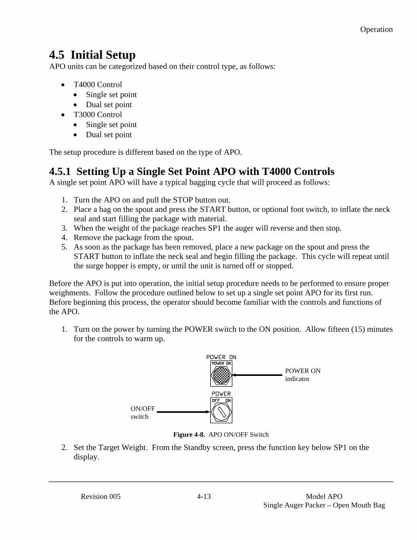
Operation
Revision 005 4-13 Model APO
Single Auger Packer – Open Mouth Bag
4.5 Initial Setup APO units can be categorized based on their control type, as follows:
• T4000 Control • Single set point • Dual set point
• T3000 Control • Single set point • Dual set point
The setup procedure is different based on the type of APO.
4.5.1 Setting Up a Single Set Point APO with T4000 Controls A single set point APO will have a typical bagging cycle that will proceed as follows:
1. Turn the APO on and pull the STOP button out. 2. Place a bag on the spout and press the START button, or optional foot switch, to inflate the neck
seal and start filling the package with material. 3. When the weight of the package reaches SP1 the auger will reverse and then stop. 4. Remove the package from the spout. 5. As soon as the package has been removed, place a new package on the spout and press the
START button to inflate the neck seal and begin filling the package. This cycle will repeat until the surge hopper is empty, or until the unit is turned off or stopped.
Before the APO is put into operation, the initial setup procedure needs to be performed to ensure proper weighments. Follow the procedure outlined below to set up a single set point APO for its first run. Before beginning this process, the operator should become familiar with the controls and functions of the APO.
1. Turn on the power by turning the POWER switch to the ON position. Allow fifteen (15) minutes for the controls to warm up.
Figure 4-8. APO ON/OFF Switch
2. Set the Target Weight. From the Standby screen, press the function key below SP1 on the display.
ON/OFF switch
POWER ON indicator

Operation
Model APO
Single Auger Packer – Open Mouth Bag 4-14 Revision 005
Figure 4-9. Initial Setup – Single Set Point APO
3. When the SP1 adjustment screen appears, use the up, down, left, and right arrows to adjust the SP1 setting.
Figure 4-10. SP1 Adjustment Screen
4. When the adjustment to the SP1 setting is complete, press the function key below the EXIT on the display.
Note: Due to the weight of product in free fall, SP1 is typically set .3 to .7 lbs below the desired target weight. How much below the desired package weight will depend on the flow characteristics of the product.
5. Place a bag on the spout. 6. Press the START button, or optional foot switch. The APO will inflate the neck seal and will
begin filling the package with material. After SP1 has been reached, and the auger has stopped. BEFORE removing the package, check the weight display to see how close the actual package weight is to the target weight. If the actual package weight is more than or less than the target weight go back and adjust SP1 up or down by an amount equal to the difference between the target weight and actual weight.
7. Remove the package. 8. Install a new package on the spout and press the START button, or optional foot switch, to
inflate the neck seal. Once again, the APO will begin filling the package with material. After SP1 has been reached, and the auger has stopped, check the weight display to make sure that actual weight matches the target weight. If the actual weight is on target, remove the package and install a new package on the spout and press the START button to inflate the neck seal. There will be a short delay before the auger begins filling the new package. It is important to make any SP1 correction before the package is removed. It may take several cycles before to get the machine properly set up for that specific product.
Press this function key
Press this function key once the desired SP1 point has been set
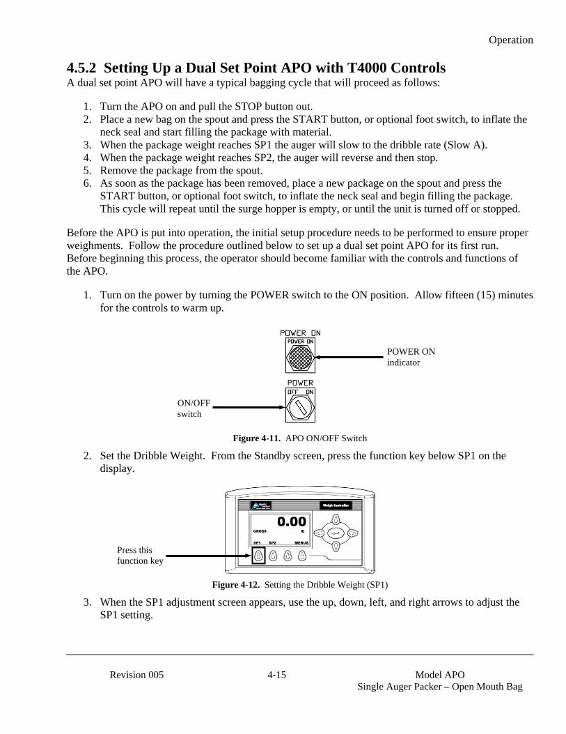
Operation
Revision 005 4-15 Model APO
Single Auger Packer – Open Mouth Bag
4.5.2 Setting Up a Dual Set Point APO with T4000 Controls A dual set point APO will have a typical bagging cycle that will proceed as follows:
1. Turn the APO on and pull the STOP button out. 2. Place a new bag on the spout and press the START button, or optional foot switch, to inflate the
neck seal and start filling the package with material. 3. When the package weight reaches SP1 the auger will slow to the dribble rate (Slow A). 4. When the package weight reaches SP2, the auger will reverse and then stop. 5. Remove the package from the spout. 6. As soon as the package has been removed, place a new package on the spout and press the
START button, or optional foot switch, to inflate the neck seal and begin filling the package. This cycle will repeat until the surge hopper is empty, or until the unit is turned off or stopped.
Before the APO is put into operation, the initial setup procedure needs to be performed to ensure proper weighments. Follow the procedure outlined below to set up a dual set point APO for its first run. Before beginning this process, the operator should become familiar with the controls and functions of the APO.
1. Turn on the power by turning the POWER switch to the ON position. Allow fifteen (15) minutes for the controls to warm up.
Figure 4-11. APO ON/OFF Switch
2. Set the Dribble Weight. From the Standby screen, press the function key below SP1 on the display.
Figure 4-12. Setting the Dribble Weight (SP1)
3. When the SP1 adjustment screen appears, use the up, down, left, and right arrows to adjust the SP1 setting.
ON/OFF switch
POWER ON indicator
Press this function key
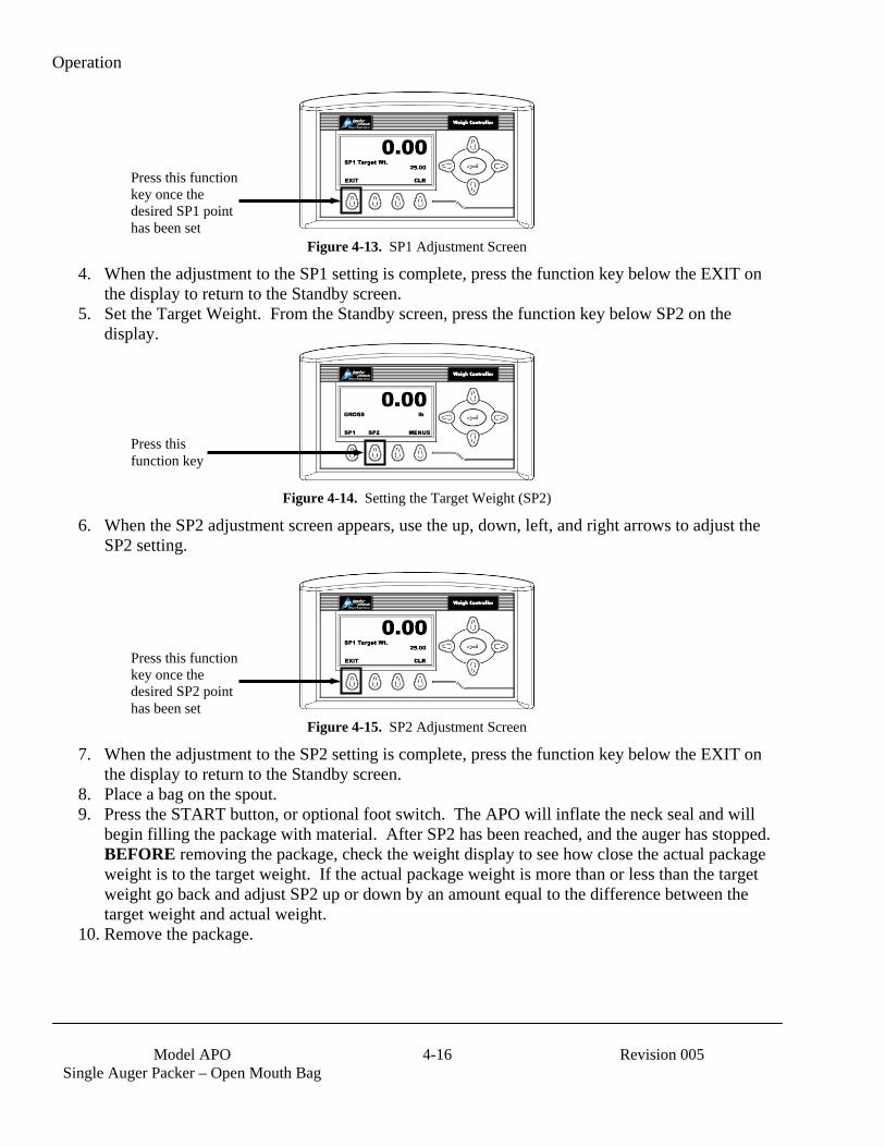
Operation
Model APO
Single Auger Packer – Open Mouth Bag 4-16 Revision 005
Figure 4-13. SP1 Adjustment Screen
4. When the adjustment to the SP1 setting is complete, press the function key below the EXIT on the display to return to the Standby screen.
5. Set the Target Weight. From the Standby screen, press the function key below SP2 on the display.
Figure 4-14. Setting the Target Weight (SP2)
6. When the SP2 adjustment screen appears, use the up, down, left, and right arrows to adjust the SP2 setting.
Figure 4-15. SP2 Adjustment Screen
7. When the adjustment to the SP2 setting is complete, press the function key below the EXIT on the display to return to the Standby screen.
8. Place a bag on the spout. 9. Press the START button, or optional foot switch. The APO will inflate the neck seal and will
begin filling the package with material. After SP2 has been reached, and the auger has stopped. BEFORE removing the package, check the weight display to see how close the actual package weight is to the target weight. If the actual package weight is more than or less than the target weight go back and adjust SP2 up or down by an amount equal to the difference between the target weight and actual weight.
10. Remove the package.
Press this function key once the desired SP1 point has been set
Press this function key
Press this function key once the desired SP2 point has been set
Operation
Revision 005 4-17 Model APO
Single Auger Packer – Open Mouth Bag
11. Install a new package on the spout and press the START button, or optional foot switch, to inflate the neck seal. Once again, the APO will begin filling the package with material. After SP2 has been reached, and the auger has stopped, check the weight display to make sure that actual weight matches the target weight. If the actual weight is on target, remove the package and install a new package on the spout and press the START button to inflate the neck seal. There will be a short delay before the auger begins filling the new package. It is important to make any SP1 correction before the package is removed. It may take several cycles before to get the machine properly set up for that specific product.
Note: Also keep in mind that every time the auger speed is changed, SP2 will most likely need to be adjusted. This adjustment alters the amount of product moving through the spout, thus changing the amount of material in free fall.
4.5.3 Using the T3000 to Set Points and Feeder Speeds APO units equipped with the T3000 can be configured as a single set point or a dual set point unit. Regardless of how the T3000 is going to be used, the Pre-Fill procedures are the same as are covered in the T3000 single set point setup procedures below. Units that use multiple fill speeds have additional steps that need to be taken to program those fill speeds.
4.5.3.1 T3000 Single Set Point An APO with the T3000 that is going to be used as a single set point unit utilizes a single fill speed (bulk rate). The Pre-Fill procedure for a single set point unit is listed below:
Important: If the wrong number is entered accidentally, the user can press the clear key to erase the entry, or they can press the Exit key to back up to the previous menu.
1. Position the first container for filling. 2. Check the T3000 to make sure the Filler is configured for the specific product that is being used. 3. Make sure the T3000 is in Standby Mode. 4. Press the User key to pull up the User Menu. 5. Press the Clear key to erase the current entry. 6. Enter the user ID. 7. Press the Enter key. 8. If the product shown on the display is the product that is going to be packaged, the setup is
complete. If not, continue to step 9. 9. If the product shown on the Standby Menu is not the product being packaged, do the following:
a. Press the Product key once. A list of products that have been programmed into the control panel will appear. The currently selected product will be displayed.
b. The operator can change the product using the up or down arrow keys to scroll through the available list of products. When the desired product is found, position the cursor next to it and press the Enter key. The menu for that product will appear, with the cursor adjacent to the Accept Settings line. Press Enter again to accept the settings, or use the up/down arrows to scroll through the available parameters for that product. To change a specific parameter, place the cursor next to that line and key in the new value for that parameter, followed by pressing the Enter key. When finished, scroll back to the Accept Settings line and press the Enter key to accept the changes.

Operation
Model APO
Single Auger Packer – Open Mouth Bag 4-18 Revision 005
4.5.3.2 T3000 Dual Set Point In addition to the steps shown under the T3000 single set point procedures, a dual set point APO needs a secondary fill speed (dribble rate). A dual set point unit can typically utilize a higher bulk rate than a single set point unit. This makes for a more efficient operation.
Setting the feed rates is accomplished using the Speed menu. Select the Speed/6 key, then use the arrow keys to adjust the bulk and dribble rates. The bulk fill rate will appear as Fast A in the menu system, while the dribble rate will appear as Slow A.

Preventive Maintenance
Revision 005 5-1 Model APO
Single Auger Packer – Open Mouth Bag
Chapter 5 Preventive Maintenance
5.1 General Description To minimize downtime, preventive maintenance should be made a priority. Proper preventive maintenance practices will also extend the life of the equipment. Developing a preventive maintenance schedule will ensure that critical maintenance procedures are not missed.
5.2 Daily Maintenance Procedures At the start of each working day, the following maintenance tasks should be performed before starting the machine:
1. Thoroughly clean the machine. 2. Check the calibration, using a known weight. 3. Drain any water that may have accumulated in the water separator in the air supply line.
5.2.1 Cleaning Keeping the APO clean is an important part of the daily maintenance tasks. Remove any dust and/or dirt that may have accumulated on a daily basis. Keeping the unit clean will keep debris from entering the control mechanisms, which could cause the performance of the APO to suffer. Also, by taking the time to clean the APO on a daily basis, the operator will be able to give the APO a thorough inspection. Take the time to inspect all wiring, air supply lines and connections, and components for possible damage.
5.2.2 Check Calibration On a daily basis, check the calibration of the machine using a known weight. If calibration is required, refer to 3.7 Calibration.
5.2.3 Drain Water From the Water Separator It is very important to remove unwanted moisture from the incoming air to ensure proper operating of the pneumatic components. At the beginning of each day, the operator should empty the water from the water separator. Follow the process below to drain the water.
1. Disconnect the air supply line. 2. Place a container under the drain valve. 3. There are two types of drain valves, follow the appropriate step below to open and close the
drain valve: a. If the water separator has a pin-type drain valve, press the pin upward and hold it in to
drain the water. Release the pin once all water has drained. b. If the water separator has a screw-type drain valve, turn the screw cap counter-clockwise
to completely loosen the cap. After the water has completely drained, lightly push the cap upward to engage the threads and turn the cap clockwise until snug.
4. Discard the water from the container. 5. Reconnect the air supply line.
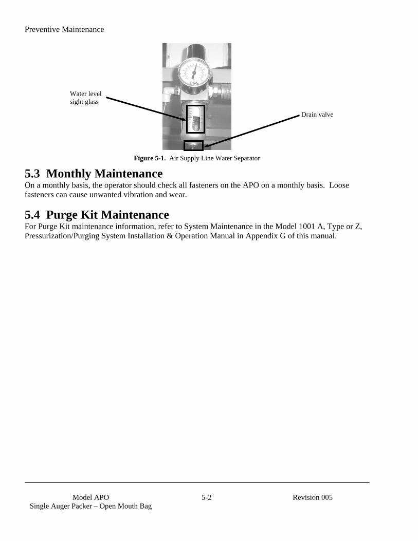
Preventive Maintenance
Model APO
Single Auger Packer – Open Mouth Bag 5-2 Revision 005
Figure 5-1. Air Supply Line Water Separator
5.3 Monthly Maintenance On a monthly basis, the operator should check all fasteners on the APO on a monthly basis. Loose fasteners can cause unwanted vibration and wear.
5.4 Purge Kit Maintenance For Purge Kit maintenance information, refer to System Maintenance in the Model 1001 A, Type or Z, Pressurization/Purging System Installation & Operation Manual in Appendix G of this manual.
Water level sight glass
Drain valve
Troubleshooting
Revision 005 6-1 Model APO
Single Auger Packer – Open Mouth Bag
Chapter 6 Troubleshooting
6.1 General Description When a problem occurs, proper troubleshooting techniques will allow maintenance personnel to quickly identify the problem.
6.2 The Troubleshooting Process The actual troubleshooting process is just as important as the repair process. Use the following troubleshooting keys to assist with the troubleshooting process:
• Identify the trouble symptom o What is the problem? o What were the circumstances when the problem occurred? o Could weather be a factor? o Are there any other contributing factors?
• Sectionalize the problem o Look at the problem. o What area of the machine is the problem occurring in? o Has anything changed recently?
• Isolate the problem o Try simple things first. o Observe indication and trouble codes. o Check test points. o Avoid complicating the problem.
6.3 Trouble Symptoms Use the following information to assist in troubleshooting.
6.3.1 Machine Will Not Power On If the turns the POWER switch to the ON position and the APO does not power up, follow the steps below to determine the cause.
1. Check for the availability of power (115 VAC for control circuits, 230 or 460 VAC for the feed and drive circuits) to the machine from the power outlets. Refer to the electrical schematics in Appendix D for exact current and voltage specifications.
2. Check the main fuse inside the cabinet to see if it has blown and needs replaced. If the fuse is blown, replace it with a fuse of the same type and rating as outlined in the electrical schematics for that specific machine.
3. Check to for 110 VAC on the input side of the power switch when it is turned off. If power is not available at the input, check for an open circuit in the wiring between the fuse and the switch.
4. Turn the switch to the ON position and check for voltage on the output of the switch. If power is not available at the output, replace the contacts.

Troubleshooting
Model APO
Single Auger Packer – Open Mouth Bag 6-2 Revision 005
6.3.2 Machine Will Not Start When the Start Button is Pressed If the machine will not begin the fill cycle when the start button is pressed, even though the power is turned on, and the STOP button has been pulled out, use the steps below to troubleshoot the problem.
1. Check the LEDs on the PLC. The green power light and a green run light should be illuminated. If a fault LED is illuminated, refer to 6.4.3 PLC Error Messages.
2. Push the STOP button in. Turn the AUTO/MANUAL switch to MANUAL. Pull the STOP button out. Switch the AUTO/MANUAL switch to AUTO. Push the START button to see if the machine will start.
6.3.3 Inflatable Neck Seal Will Not Inflate If the inflatable neck seal does not inflate when the start button is pressed, follow the steps below to troubleshoot the problem.
1. Check the gum rubber seal for holes or tears. Replace if needed. Refer to 7.3.2 Inflatable Neck Seal Replacement.
2. Check for compressed air to the seal by removing the air supply line from the quick connect fitting. If air is not present, go to the next step.
3. Check the neck seal pressure switch, located on the upper left hand side of the machine, for proper operation. Adjust the pressure switch as required. Refer to 7.2.3 Inflatable Neck Seal Pressure Switch Adjustment.
4. Check the MAC valve on the rear of the machine for proper operation. The valve is driven by an output from the PLC. When energized, the coil opens the valve to inflate seal. If the PLC output is energized, 110 VAC should be present at the coil of the valve. Check for air going to valve. Check the valve to see if it changes position. If power is present, but valve does not change, replace the valve. Refer to 7.3.23 MAC Valve Replacement.
6.3.4 Scale is Not Accurate If the load cell is providing inaccurate readings, check the following:
1. Check for proper calibration. Refer to 3.7 Calibration. 2. Check the hopper to make sure an adequate supply of material is available in the product hopper
to ensure a consistent head pressure. 3. Check to make sure there is nothing restricting material flow from the hopper. 4. Check that hoses or other components are not coming into contact with the spout or weigh mast. 5. Check the flex leaves to make sure they are not bent or broken. 6. On dual set point machines, check the settings of the set points. Adequate time between set
points is critical. After SP1 is reached, a minimum of two seconds should pass before SP2 is reached.
7. Check the load cell for damage. 8. Check the zero of the machine. Make sure it stays on zero and doesn’t jump around. If the
display does not remain steady at zero, a faulty load cell may be the culprit.
Troubleshooting
Revision 005 6-3 Model APO
Single Auger Packer – Open Mouth Bag
6.3.5 Scale Does Not Return to Zero If the scale reading does not return to zero after package has been removed from the spout, check the following items:
1. Check the flex leaves to make sure that they are not missing or damaged. If one or more of the flex leaves shows signs of damage or is missing, replace them. Refer to 7.3.7 Flex Leaf Replacement.
2. Check the calibration of the APO. Refer to 3.7 Calibration. 3. Check for anything that might interfere with the natural motion of the weigh mast. Any items,
such as cords, hoses, etc., that would impede or change the movement of the weigh mast must be removed.
4. Check the auger to make sure it is not touching the spout, or any weighed portion of the unit. If the auger is touching the weighed portion of the machine, the auto-tare feature may need to be turned on.
5. Check to see if product is building up in the transition or any other weighed portion of the machine. If product buildup is occurring, the auto-tare feature may need to be turned on.
6.3.6 The Weighments are Always Too Light Troubleshooting for weighments that are consistently coming up too light varies depending on the amount of time required to fill the package.
6.3.6.1 Fast Filling Products (Less Than 5 Seconds of Fill Time) 1. Try lowering the dribble value. The scale must have time to react. If the product is flowing into
the package on the bulk rate too fast, the flow can cause a spike that will shut flow off too early. 2. Try lowering the bulk feed rate. 3. Increase the cutoff to a higher weight setting. 4. Check the unit to make sure that the displayed weight equals the actual package weight. If it
does not, calibrate the machine. Refer to 3.7 Calibration.
6.3.6.2 Normal Filling Products (5 Seconds or More of Fill Time) 1. Increase the cutoff to a higher weight setting 2. Ensure consistent product flow from the hopper above the unit 3. Ensure that the dribble setting is a lower weight than the cutoff setting. 4. Ensure that the displayed weight, on the packer, equals the actual weight of the package. If it
does not, calibrate the machine. Refer to 3.7 Calibration.
6.3.7 The Weighments are Always Too Heavy If the APO is consistently filling the package and stopping above the target weight, follow the steps below:
1. Adjust the cutoff setting to a lighter weight. 2. If operating a dual set point unit, ensure that there is a noticeable dribble period. After SP1 is
reached, a minimum of two seconds should pass before SP2 is reached. 3. Validate that the weight shown on the weight display equals the actual weight of the package. If
it does not, calibrate the machine. Refer to 3.7 Calibration. 4. Slow the fill time of the package. It is possible to feed product too fast.

Troubleshooting
Model APO
Single Auger Packer – Open Mouth Bag 6-4 Revision 005
6.3.8 Load Cell Fails Frequently If the load cells on an APO are failing frequently, check the following items:
1. Check the operating conditions to make sure that the load cell is not jarred, jerked, or being loaded with a sudden excessive force.
2. Check the load cell to make sure that it is not being over loaded. Consider the package size being weighed, plus the dead load of the weighing mechanism.
3. Check the scale output to verify that the proper excitation voltage is being applied to the load cell.
6.3.9 The Weighments Fluctuate Between Too Light and Too Heavy If the APO is inconsistent in delivering package weights, and the weights are always either too heavy, or too light, follow the steps below:
1. Verify that the product flow is consistent and stable. 2. Check for consistent head pressure of product above the machine. Head pressure is the amount
of product that is always in the hopper immediately above the packer. It is very important to keep the packer from running out of material. As the packer runs out of product the weighment accuracy will vary widely. Magnum Systems recommends that a low level sensor be installed on the product hopper. If the low level condition is met, the fill routine should pause until more product is put in the hopper. A good rule of thumb is to have enough product in the hopper to fill approximately 20 packages at all times. This amount may vary slightly depending upon product characteristics.
3. Verify a stable zero reading. The zero reading should not fluctuate more than a tenth. If the reading fluctuates more than a tenth there is a possible load cell or weight indicator problem. Refer to 6.3.5 Scale Does Not Return to Zero.
4. Verify that the weight display is displaying a stable weight reading. Hang a calibration weight or a known weight on the spout. If the weight display reading fluctuates more than a tenth or two it indicates a possible load cell or weight indicator problem. Refer to 6.3.5 Scale Does Not Return to Zero.
5. Check the load cell connection points to ensure a good electrical connection tighten as needed. 6. Check the response of the solenoids. The solenoids should respond immediately when voltage is
applied.
6.3.10 APO Does Not Start After The START Button Is Pushed If the APO will not start when the START button is pressed, use the steps below find the cause.
1. Check the start switch to see if the contacts are working properly. 2. Check the voltage to and from the start switch should be 110 volts. 3. Check the MAC valve to see if it is getting voltage and the valve is functioning properly. 4. Check to see if the timer for delay of start is getting voltage and see if the valve on it is changing
states. 5. Check to make sure the motor is receiving power.

Troubleshooting
Revision 005 6-5 Model APO
Single Auger Packer – Open Mouth Bag
6.4 System Alarms During the filling process, conditions may occur that result in an alarm from the APO. Depending on the type of controller used, the alarms will vary.
6.4.1 T4000 Alarms During the filling process, conditions may occur that result in one of the following T4000 alarms:
• A/D Failure Error! – An internal electronics error has occurred. Retry the operation. If the failure error re-occurs, power the machine down, then restart the machine and try the operation again. If the operation still fails, contact Magnum Systems technical assistance.
• A/D Convert Error! – The input from the load cell is outside of the acceptable range. Check the load cell for damage. If a new load cell has been installed, check the rating of the load cell to make sure that the correct load cell has been installed.
• Motion Error! – The controller has detected that the vessel or product is in motion and the controller cannot finalize the weighment. Check the machine settings and retry.
• Trad Cal Error! – An error occurred during the calibration process. Try to calibrate the machine again. If the error occurs again, contact Magnum Systems technical assistance.
• C2 Cal Error! – This error should not occur, as Magnum Systems does not use C2 type load cells. If this error does occur, contact Magnum Systems technical assistance.
• Too Lo Error! – Verify that the load cell signal level is 0-15 mV. Verify that there is enough weight on the scale. Perform Span then go back and Zero.
• Too Hi Error! – Verify that the load cell signal level is 0-15mV. Verify that there is not too much weight on the scale. Perform Span then go back and Zero.
• No C2 Sensor! – Instrument did not detect a C2 Load Sensor. This error should appear if C2 Cal is selected, as Magnum Systems does not use C2 type load cells. If this error does occur, contact Magnum Systems technical assistance.
• CAL Failed! – There are too few counts between Zero and Span. Reset either of the values, so that the counts are more than 1,000 counts of each other.
• C2 Caps Unequal! – This error should not occur, as Magnum Systems does not use C2 type load cells. If this error does occur, contact Magnum Systems technical assistance.
• HI/LO Too Close! – The Zero and Span values are not more than 1,000 counts from each other or there is no change, or there is a negative change. Reset either of the values, so that the counts are more than 1,000 counts of each other.
• Function Error! – The operator has pressed a function button and the function did not work. Try the function again. If it does not work, cycle the power off and on. If it still doesn’t work, contact Magnum Systems technical assistance.
• Not Allowed! – The value entered by the operator is outside of the range that is allowed. The operator should try another value that is within the acceptable range.
• Security Violation! – User signed in with a password that does not allow performance of a certain function or entry to certain menus. Security level of the user identified in the User ID, too low for the menu or function.
• Overrange – The final package weight has exceeded the set point target. • Gross ADC Error – The controller has detected a load cell error. Check all load cell connections.
Repair connections as necessary. Check the load cell for damage. Replace the load cell if necessary. Refer to 7.3.13 Load Cell Replacement.
Troubleshooting
Model APO
Single Auger Packer – Open Mouth Bag 6-6 Revision 005
6.4.2 T3000 Alarms There are three different categories of alarms:
• Fill Alarms • Jog Alarms • Filler Discharge Alarms
For a full description of these alarms, refer to Chapter 3: Operating Procedures/Filler, of the Magnum Systems Filler/Dispenser/IBC T3000 User Guide, that is included in Appendix E of this manual.
6.4.3 PLC Error Messages The Allen-Bradley PanelView Display provides the user with several types of messages:
• Status Messages • Reminder Messages • Warning Messages • Fault Messages
To be able to access these messages, a properly equipped computer or handheld device must be connected to the PLC.
6.4.3.1 Status Messages Status messages are used to indicate to the operator that the control panel is performing an operation that may limit access to the terminal. Examples are application downloads or communication problems. The message disappears when the control panel completes the operation or when the condition is satisfied.
6.4.3.2 Reminder Messages Reminder messages are used to indicate a minor fault or mistake. Reminder messages appear when an invalid operation is attempted, such as entering an out-of-range value. Pressing any key removes the message.
6.4.3.3 Warning Messages Indicates the operation may produce undesirable results. The operator must respond to warning messages as indicated in the message.
6.4.3.4 Fault Messages Indicates the terminal has detected a condition, which will prevent further operation. The current application will stop. The operator must reset the terminal (power cycle) to recover from this type of error.
6.5 Purge Kit Troubleshooting For Purge Kit troubleshooting information, refer to Trouble – Shooting Procedures in the Model 1001 A, Type or Z, Pressurization/Purging System Installation & Operation Manual in Appendix G of this manual.
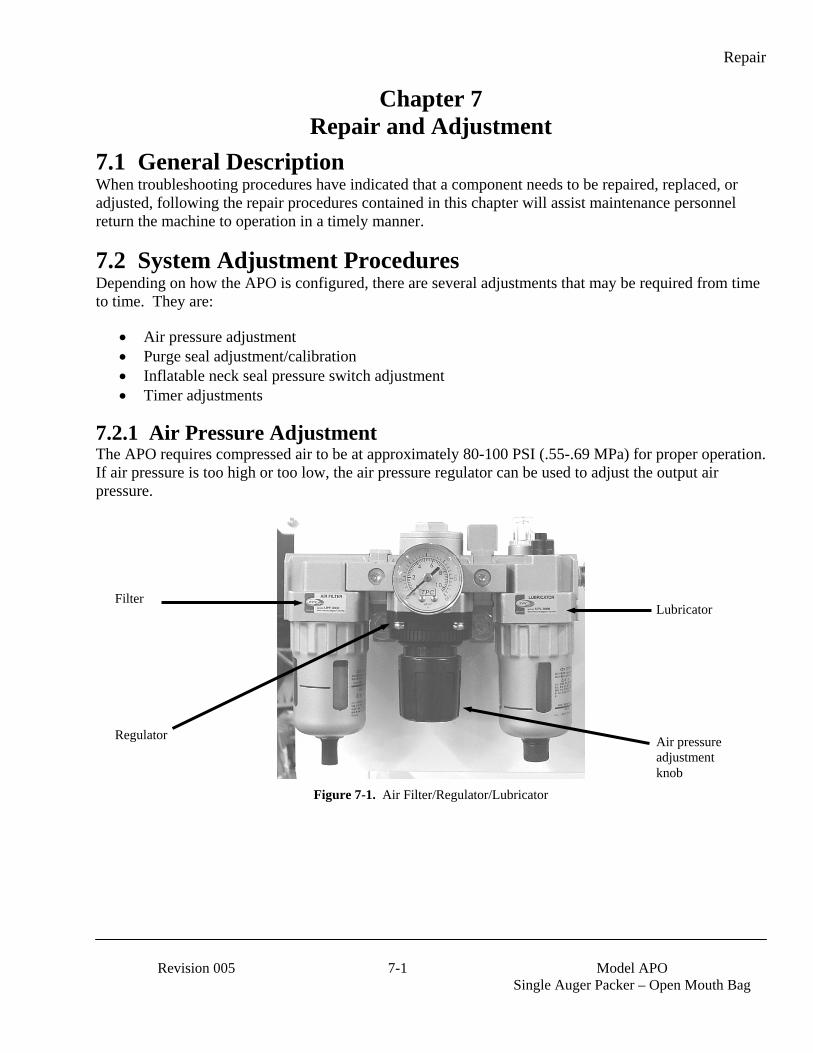
Repair
Revision 005 7-1 Model APO
Single Auger Packer – Open Mouth Bag
Chapter 7 Repair and Adjustment
7.1 General Description When troubleshooting procedures have indicated that a component needs to be repaired, replaced, or adjusted, following the repair procedures contained in this chapter will assist maintenance personnel return the machine to operation in a timely manner.
7.2 System Adjustment Procedures Depending on how the APO is configured, there are several adjustments that may be required from time to time. They are:
• Air pressure adjustment • Purge seal adjustment/calibration • Inflatable neck seal pressure switch adjustment • Timer adjustments
7.2.1 Air Pressure Adjustment The APO requires compressed air to be at approximately 80-100 PSI (.55-.69 MPa) for proper operation. If air pressure is too high or too low, the air pressure regulator can be used to adjust the output air pressure.
Figure 7-1. Air Filter/Regulator/Lubricator
Air pressure adjustment knob
Lubricator
Regulator
Filter
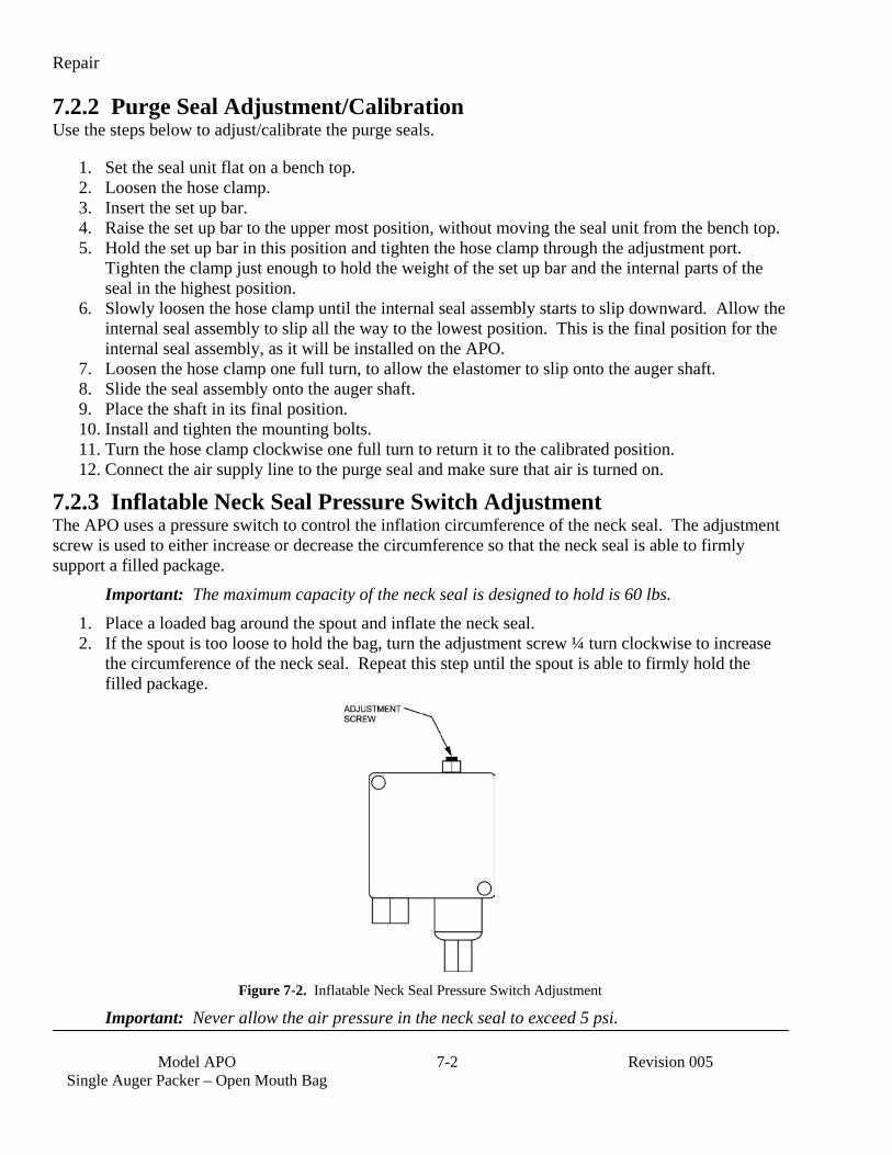
Repair
Model APO
Single Auger Packer – Open Mouth Bag 7-2 Revision 005
7.2.2 Purge Seal Adjustment/Calibration Use the steps below to adjust/calibrate the purge seals.
1. Set the seal unit flat on a bench top. 2. Loosen the hose clamp. 3. Insert the set up bar. 4. Raise the set up bar to the upper most position, without moving the seal unit from the bench top. 5. Hold the set up bar in this position and tighten the hose clamp through the adjustment port.
Tighten the clamp just enough to hold the weight of the set up bar and the internal parts of the seal in the highest position.
6. Slowly loosen the hose clamp until the internal seal assembly starts to slip downward. Allow the internal seal assembly to slip all the way to the lowest position. This is the final position for the internal seal assembly, as it will be installed on the APO.
7. Loosen the hose clamp one full turn, to allow the elastomer to slip onto the auger shaft. 8. Slide the seal assembly onto the auger shaft. 9. Place the shaft in its final position. 10. Install and tighten the mounting bolts. 11. Turn the hose clamp clockwise one full turn to return it to the calibrated position. 12. Connect the air supply line to the purge seal and make sure that air is turned on.
7.2.3 Inflatable Neck Seal Pressure Switch Adjustment The APO uses a pressure switch to control the inflation circumference of the neck seal. The adjustment screw is used to either increase or decrease the circumference so that the neck seal is able to firmly support a filled package.
Important: The maximum capacity of the neck seal is designed to hold is 60 lbs. 1. Place a loaded bag around the spout and inflate the neck seal. 2. If the spout is too loose to hold the bag, turn the adjustment screw ¼ turn clockwise to increase
the circumference of the neck seal. Repeat this step until the spout is able to firmly hold the filled package.
Figure 7-2. Inflatable Neck Seal Pressure Switch Adjustment
Important: Never allow the air pressure in the neck seal to exceed 5 psi.

Repair
Revision 005 7-3 Model APO
Single Auger Packer – Open Mouth Bag
3. If the spout is too tight and tears the back of the package, turn the adjustment screw ¼ turn counter-clockwise to decrease the circumference of the neck seal. Repeat this step until the spout is able to firmly hold the filled packaged without tearing the package.
7.2.4 Blow Out Switch Adjustment The blow out switch must be properly adjusted for the APO to function properly. The inflatable neck seal must be allowed to inflate enough to hold the heaviest bag used. If the neck seal is allowed to over-inflate, the result may be a ripped bag or ruptured neck seal.
Important: Ensure that the hopper is empty before beginning the adjustment procedure. Failure to do so will result in the product spilling onto the floor.
Important: During the blow out switch adjustment procedure, the operator should be prepared to press the STOP button to prevent rupturing the neck seal.
Important: The maximum capacity of the neck seal is designed to hold is 60 lbs.
1. Empty the hopper. 2. Place an empty bag on the spout. 3. Adjust the pressure switch until the neck seal is able to hold the bag in place. 4. Grab the edges of the bag and pull down with enough force to fill the heaviest bag used. The bag
should not slide off the inflatable spout before this weight is reached. If it does, increase the pressure on the inflatable seal slightly and pull on the bag again. Repeat until the bag will stay on the spout while filling the heaviest bag used.
5. Before removing the bag, adjust the blow out switch so it is approx 1/8” away from the bag. Ensure the blowout switch does not activate with the bag on the inflated neck.
6. Now remove the bag from the spout and press the start button to inflate the neck seal. 7. With the bag missing from the spout, the neck seal should depress the blow out switch enough to
shut off the fill cycle and deflate the neck seal. Adjust as required.
7.2.5 Auger Shaft Seal Adjustment The auger shaft seals should be adjusted any time they are replaced or if product begins leaking around the seals. When adjusting the tension on the seals, put just enough tension on the seals to prevent the product from leaking out. Too much tension will result in excess heat and will adversely affect the performance of the machine. Follow the procedure below to adjust the auger shaft seals:
1. Loosen the jam nuts on the seal tension adjustment bolts. 2. Adjust seal tension using the seal tension adjustment bolts.
a. To increase the tension on the seal, turn the seal tension bolts clockwise b. To decrease the tension on the seal, turn the seal tension bolts counter-clockwise.
3. Once the adjustment is complete, tighten the jam nuts to prevent the seal tension bolts from backing out.
7.2.6 Timer Adjustments The APO has several operational features that are controlled via logical timers that are programmed into the PLC. Access to the timers and adjustment of the timers is accomplished using the PV300 control panel. Refer to 4.3.4.1 PV300 Menus for more information on using the PV300.

Repair
Model APO
Single Auger Packer – Open Mouth Bag 7-4 Revision 005
7.3 Component Replacement Procedures Over time, components on the APO may become worn or damaged. If this occurs, follow the procedures in this section to repair or replace individual components.
WARNING When replacing parts, it is critical that only parts approved by Magnum Systems are used.
7.3.1 Spout Replacement Due to the abrasiveness of some products, the spout will require periodic replacement. Use the procedures below to replace the spout.
7.3.1.1 Spout Removal 1. Disconnect the power from the APO. 2. Disconnect the compressed air supply line from the APO at the Filter/Regulator/Lubricator. 3. Label and disconnect the air supply lines from the spout at the quick connect fittings. 4. Remove the vacuum probe. Refer to 7.3.21 Vacuum Probe Replacement. 5. Remove the dust hood. Refer to 7.3.19 Dust Hood Replacement. 6. Remove the transition. Refer to 7.3.18 Transition Replacement. 7. Remove the blow out switch. Refer to 7.3.20 Blow Out Switch Replacement. 8. Remove the two spout mounting bolts. 9. Support the spout with one hand and remove the alignment pin. 10. Remove the spout by sliding it up and out of the mounting bracket.
Figure 7-3. Open Mouth Bag Spout Mount
Spout mounting bolts Retaining pin
Slide bracket
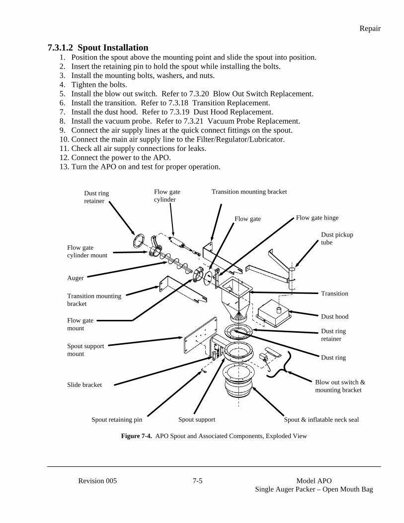
Repair
Revision 005 7-5 Model APO
Single Auger Packer – Open Mouth Bag
7.3.1.2 Spout Installation 1. Position the spout above the mounting point and slide the spout into position. 2. Insert the retaining pin to hold the spout while installing the bolts. 3. Install the mounting bolts, washers, and nuts. 4. Tighten the bolts. 5. Install the blow out switch. Refer to 7.3.20 Blow Out Switch Replacement. 6. Install the transition. Refer to 7.3.18 Transition Replacement. 7. Install the dust hood. Refer to 7.3.19 Dust Hood Replacement. 8. Install the vacuum probe. Refer to 7.3.21 Vacuum Probe Replacement. 9. Connect the air supply lines at the quick connect fittings on the spout. 10. Connect the main air supply line to the Filter/Regulator/Lubricator. 11. Check all air supply connections for leaks. 12. Connect the power to the APO. 13. Turn the APO on and test for proper operation.
Figure 7-4. APO Spout and Associated Components, Exploded View
Flow gate cylinder
Dust ring retainer
Auger
Flow gate cylinder mount
Transition mounting bracket
Flow gate
Dust pickup tube
Flow gate hinge
Transition Transition mounting bracket
Spout support mount
Dust hood
Dust ring retainer
Blow out switch & mounting bracket
Spout & inflatable neck seal Spout support Spout retaining pin
Slide bracket
Flow gate mount
Dust ring

Repair
Model APO
Single Auger Packer – Open Mouth Bag 7-6 Revision 005
7.3.2 Inflatable Neck Seal Replacement The APO utilizes a large spout that has an inflatable bladder that is used to hold the bag on the spout and to keep prevent product from spilling out of the bag. In the event that the inflatable neck seal fails or becomes damaged, use the procedures below to replace it.
7.3.2.1 Inflatable Neck Seal Removal 1. Turn the APO off. 2. Disconnect the input power and compressed air supply line. 3. Label and disconnect the air supply line from the quick connect fitting on the spout. 4. Fold the flap up to expose the tabs and setscrews on the top compression ring.
Figure 7-5. Sectional View of Spout and Inflatable Bladder

Repair
Revision 005 7-7 Model APO
Single Auger Packer – Open Mouth Bag
5. Using C-clamp style locking pliers, apply pressure to the tabs of the top compression ring.
Figure 7-6. Applying Pressure to Compression Ring Tabs, Using C-Clamp Locking Pliers
6. Remove the setscrews from the top compression ring. 7. Remove the C-clamp style locking pliers. 8. Slide the top compression ring off of the spout 9. Pull the bladder straight down to expose the second compression ring. 10. Using C-clamp style locking pliers, apply pressure to the tabs on the bottom compression ring. 11. Remove the setscrews from the bottom compression ring. 12. Remove the C-clamp style locking pliers. 13. Slide the bottom compression ring off of the spout.
Note: The two compression rings are different sizes and cannot be interchanged.
Note: Make note of how the bladder is positioned. The new bladder will need to be positioned in the same manner as the one that is being removed.
14. Remove the bladder. 15. Inspect the compression rings for damage or wear. If they are damaged or worn, discard them
and install new ones with the new bladder.

Repair
Model APO
Single Auger Packer – Open Mouth Bag 7-8 Revision 005
7.3.2.2 Inflatable Neck Seal Installation 1. Turn the new bladder inside out. 2. Slide the new inflatable bladder on to the spout. Position it on the spout in the same position as
the old bladder.
Note: The two compression rings are different sizes and cannot be interchanged.
3. Position the bottom compression ring. 4. Using C-clamp style locking pliers, apply pressure to the tabs on the bottom compression ring. 5. Install and tighten the setscrews for the bottom compression ring. 6. Remove the C-clamp style locking pliers. 7. Grasp the edge of the bladder at the bottom. Roll the edge outward and upward, creating a flap.
This motion will begin the process of turning the bladder right side out.
Figure 7-7. Creating the Flap
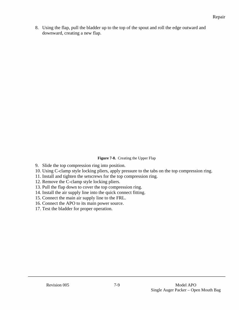
Repair
Revision 005 7-9 Model APO
Single Auger Packer – Open Mouth Bag
8. Using the flap, pull the bladder up to the top of the spout and roll the edge outward and downward, creating a new flap.
Figure 7-8. Creating the Upper Flap
9. Slide the top compression ring into position. 10. Using C-clamp style locking pliers, apply pressure to the tabs on the top compression ring. 11. Install and tighten the setscrews for the top compression ring. 12. Remove the C-clamp style locking pliers. 13. Pull the flap down to cover the top compression ring. 14. Install the air supply line into the quick connect fitting. 15. Connect the main air supply line to the FRL. 16. Connect the APO to its main power source. 17. Test the bladder for proper operation.

Repair
Model APO
Single Auger Packer – Open Mouth Bag 7-10 Revision 005
7.3.3 Air Supply Line Replacement In the event that an air supply line becomes damaged and requires replacement, follow the steps below to remove and replace the air supply line.
7.3.3.1 Air Supply Line Removal 1. Disconnect the main power cord. 2. Disconnect the main air supply line from the APO. 3. Disconnect the ends of the air supply line that is being replaced from the components that it is
connected to. Press in on the fitting collar and hold it in while pulling the air supply line free. 4. Remove any clips and/or retainers that hold the air supply lines in place. 5. Remove the air supply line, making note of how the line is routed.
7.3.3.2 Air Supply Line Installation 1. Measure the air supply line that was just removed. 2. Cut a new length of air supply line, making sure that the ends of the line are cut square. Cut the
new line to the same length of the one that was removed. 3. Route the new air supply line in the same manner as the one that was removed. 4. Insert each end of the new line into their fittings. 5. Reattach any clips and/or retainers to secure the air supply line. 6. Reconnect the main air supply line and check for any leaks. If a leak is found, disconnect the
main air supply line and then disconnect/reconnect the air connections, then reconnect the main air supply line. Repeat as necessary, until no leaks are present.
7. Reconnect the main power cord.
7.3.4 Air Fitting Replacement In the event that an air fitting becomes damaged and requires replacement, follow the steps below to remove and replace the air supply line:
7.3.4.1 Air Fitting Removal 1. Disconnect the main power cord. 2. Disconnect the main air supply line from the APO. 3. Disconnect the air supply line from the fitting by pressing in on the collar while pulling out on
the air supply line. 4. Using a wrench, unscrew the fitting.

Repair
Revision 005 7-11 Model APO
Single Auger Packer – Open Mouth Bag
7.3.4.2 Air Fitting Installation 1. Using Teflon® tape, wrap the threads of the new fitting, starting at the bottom of the thread
working toward the hex head in the same direction as the threads. 2. Screw the new fitting into the threads and use a wrench to carefully tighten the fitting.
CAUTION Over tightening the fitting can damage the fitting, or the component that it is being threaded into.
Figure 7-9. Air Supply Fitting
3. Reconnect the air supply line to the fitting. 4. Reconnect the main air supply line and check for any leaks. If a leak is found, disconnect the
main air supply line and then disconnect/reconnect the air connections, then reconnect the main air supply line. Repeat as necessary, until no leaks are present.
5. Reconnect the main power cord.
7.3.5 Air Filter/Regulator/Lubricator (FRL) Replacement In the event that the filter, the regulator, or the lubricator experiences a malfunction or becomes damaged, use the procedures below to replace the entire assembly.
7.3.5.1 FRL Assembly Removal 1. Disconnect the power from the APO. 2. Disconnect the compressed air supply line from the APO at the filter. 3. Disconnect the output compressed air line from the lubricator. 4. Remove the FRL mounting bolts and remove the FRL. 5. Drain the oil from the lubricator and discard it in accordance to local laws.
7.3.5.2 FRL Assembly Installation 1. Position the new FRL in the mounting location. Install and tighten the mounting bolts. 2. Connect the compressed air output line to the lubricator. 3. Fill the lubricator with the appropriate oil. 4. Connect the compressed air supply line to the filter. 5. Check for air leaks. 6. Connect the power to the APO.
Threads Hex head
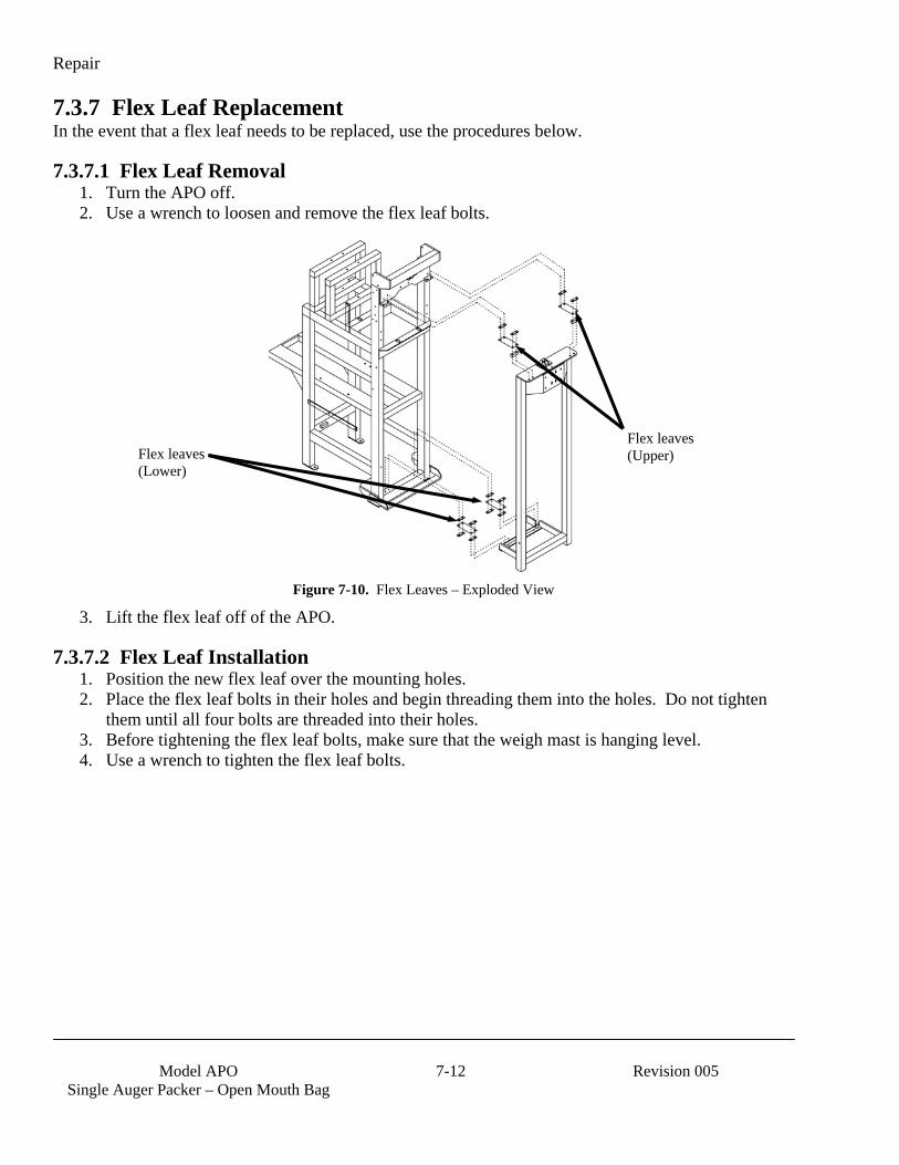
Repair
Model APO
Single Auger Packer – Open Mouth Bag 7-12 Revision 005
7.3.7 Flex Leaf Replacement In the event that a flex leaf needs to be replaced, use the procedures below.
7.3.7.1 Flex Leaf Removal 1. Turn the APO off. 2. Use a wrench to loosen and remove the flex leaf bolts.
Figure 7-10. Flex Leaves – Exploded View
3. Lift the flex leaf off of the APO.
7.3.7.2 Flex Leaf Installation 1. Position the new flex leaf over the mounting holes. 2. Place the flex leaf bolts in their holes and begin threading them into the holes. Do not tighten
them until all four bolts are threaded into their holes. 3. Before tightening the flex leaf bolts, make sure that the weigh mast is hanging level. 4. Use a wrench to tighten the flex leaf bolts.
Flex leaves (Upper) Flex leaves
(Lower)
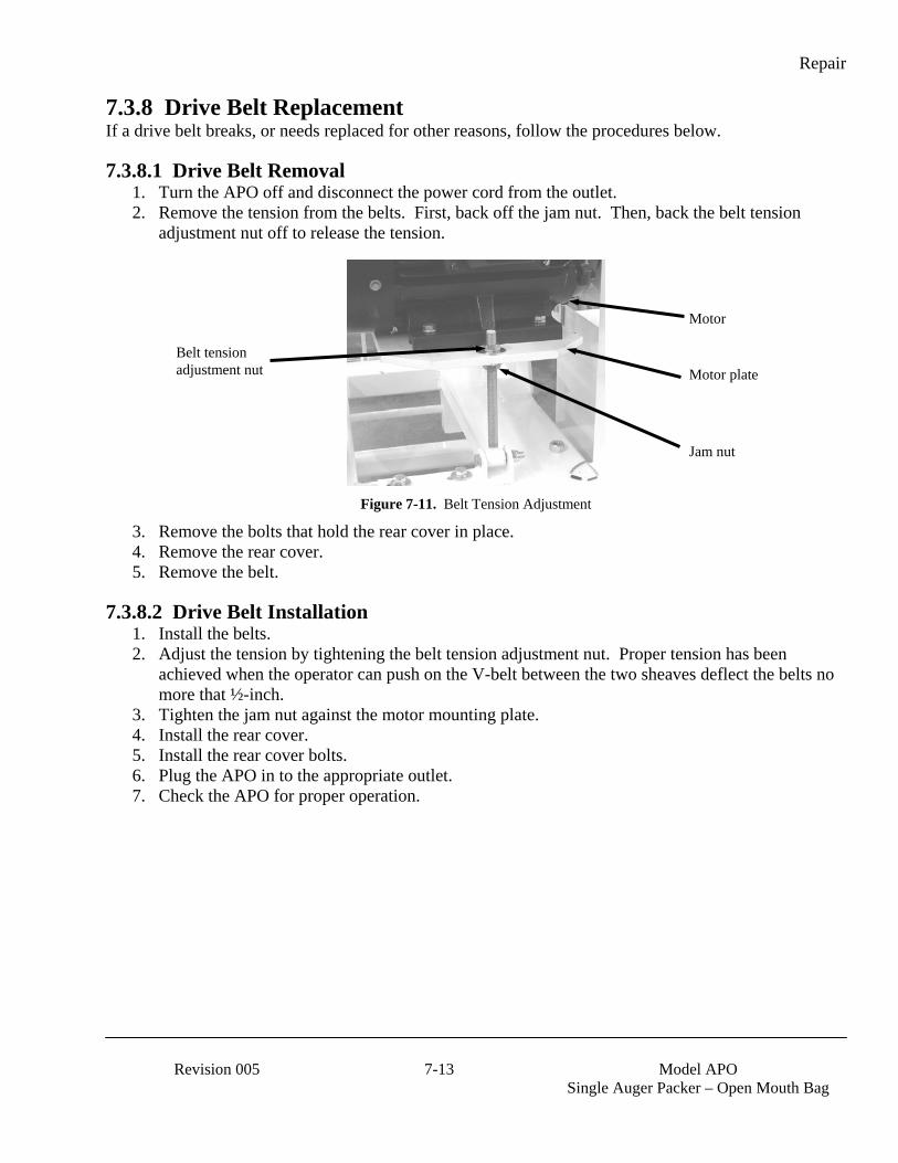
Repair
Revision 005 7-13 Model APO
Single Auger Packer – Open Mouth Bag
7.3.8 Drive Belt Replacement If a drive belt breaks, or needs replaced for other reasons, follow the procedures below.
7.3.8.1 Drive Belt Removal 1. Turn the APO off and disconnect the power cord from the outlet. 2. Remove the tension from the belts. First, back off the jam nut. Then, back the belt tension
adjustment nut off to release the tension.
Figure 7-11. Belt Tension Adjustment
3. Remove the bolts that hold the rear cover in place. 4. Remove the rear cover. 5. Remove the belt.
7.3.8.2 Drive Belt Installation 1. Install the belts. 2. Adjust the tension by tightening the belt tension adjustment nut. Proper tension has been
achieved when the operator can push on the V-belt between the two sheaves deflect the belts no more that ½-inch.
3. Tighten the jam nut against the motor mounting plate. 4. Install the rear cover. 5. Install the rear cover bolts. 6. Plug the APO in to the appropriate outlet. 7. Check the APO for proper operation.
Jam nut
Belt tension adjustment nut
Motor
Motor plate
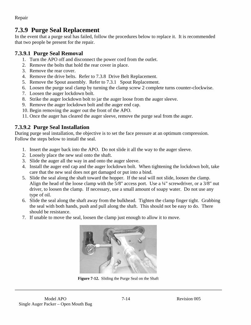
Repair
Model APO
Single Auger Packer – Open Mouth Bag 7-14 Revision 005
7.3.9 Purge Seal Replacement In the event that a purge seal has failed, follow the procedures below to replace it. It is recommended that two people be present for the repair.
7.3.9.1 Purge Seal Removal 1. Turn the APO off and disconnect the power cord from the outlet. 2. Remove the bolts that hold the rear cover in place. 3. Remove the rear cover. 4. Remove the drive belts. Refer to 7.3.8 Drive Belt Replacement. 5. Remove the Spout assembly. Refer to 7.3.1 Spout Replacement. 6. Loosen the purge seal clamp by turning the clamp screw 2 complete turns counter-clockwise. 7. Loosen the auger lockdown bolt. 8. Strike the auger lockdown bolt to jar the auger loose from the auger sleeve. 9. Remove the auger lockdown bolt and the auger end cap. 10. Begin removing the auger out the front of the APO. 11. Once the auger has cleared the auger sleeve, remove the purge seal from the auger.
7.3.9.2 Purge Seal Installation During purge seal installation, the objective is to set the face pressure at an optimum compression. Follow the steps below to install the seal.
1. Insert the auger back into the APO. Do not slide it all the way to the auger sleeve. 2. Loosely place the new seal onto the shaft. 3. Slide the auger all the way in and onto the auger sleeve. 4. Install the auger end cap and the auger lockdown bolt. When tightening the lockdown bolt, take
care that the new seal does not get damaged or put into a bind. 5. Slide the seal along the shaft toward the hopper. If the seal will not slide, loosen the clamp.
Align the head of the loose clamp with the 5/8" access port. Use a ¼" screwdriver, or a 3/8" nut driver, to loosen the clamp. If necessary, use a small amount of soapy water. Do not use any type of oil.
6. Slide the seal along the shaft away from the bulkhead. Tighten the clamp finger tight. Grabbing the seal with both hands, push and pull along the shaft. This should not be easy to do. There should be resistance.
7. If unable to move the seal, loosen the clamp just enough to allow it to move.
Figure 7-12. Sliding the Purge Seal on the Shaft
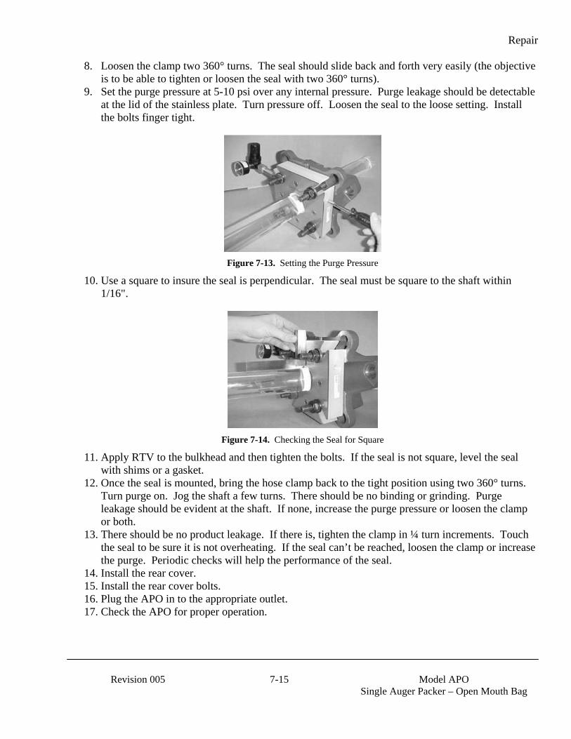
Repair
Revision 005 7-15 Model APO
Single Auger Packer – Open Mouth Bag
8. Loosen the clamp two 360° turns. The seal should slide back and forth very easily (the objective is to be able to tighten or loosen the seal with two 360° turns).
9. Set the purge pressure at 5-10 psi over any internal pressure. Purge leakage should be detectable at the lid of the stainless plate. Turn pressure off. Loosen the seal to the loose setting. Install the bolts finger tight.
Figure 7-13. Setting the Purge Pressure
10. Use a square to insure the seal is perpendicular. The seal must be square to the shaft within 1/16".
Figure 7-14. Checking the Seal for Square
11. Apply RTV to the bulkhead and then tighten the bolts. If the seal is not square, level the seal with shims or a gasket.
12. Once the seal is mounted, bring the hose clamp back to the tight position using two 360° turns. Turn purge on. Jog the shaft a few turns. There should be no binding or grinding. Purge leakage should be evident at the shaft. If none, increase the purge pressure or loosen the clamp or both.
13. There should be no product leakage. If there is, tighten the clamp in ¼ turn increments. Touch the seal to be sure it is not overheating. If the seal can’t be reached, loosen the clamp or increase the purge. Periodic checks will help the performance of the seal.
14. Install the rear cover. 15. Install the rear cover bolts. 16. Plug the APO in to the appropriate outlet. 17. Check the APO for proper operation.
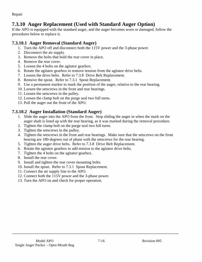
Repair
Model APO
Single Auger Packer – Open Mouth Bag 7-16 Revision 005
7.3.10 Auger Replacement (Used with Standard Auger Option) If the APO is equipped with the standard auger, and the auger becomes worn or damaged, follow the procedures below to replace it.
7.3.10.1 Auger Removal (Standard Auger) 1. Turn the APO off and disconnect both the 115V power and the 3-phase power. 2. Disconnect the air supply. 3. Remove the bolts that hold the rear cover in place. 4. Remove the rear cover. 5. Loosen the 4 bolts on the agitator gearbox. 6. Rotate the agitator gearbox to remove tension from the agitator drive belts. 7. Loosen the drive belts. Refer to 7.3.8 Drive Belt Replacement. 8. Remove the spout. Refer to 7.3.1 Spout Replacement. 9. Use a permanent marker to mark the position of the auger, relative to the rear bearing. 10. Loosen the setscrews in the front and rear bearings. 11. Loosen the setscrews in the pulley. 12. Loosen the clamp bolt on the purge seal two full turns. 13. Pull the auger out the front of the APO.
7.3.10.2 Auger Installation (Standard Auger) 1. Slide the auger into the APO from the front. Stop sliding the auger in when the mark on the
auger shaft is lined up with the rear bearing, as it was marked during the removal procedure. 2. Tighten the clamp bolt on the purge seal two full turns. 3. Tighten the setscrews in the pulley. 4. Tighten the setscrews in the front and rear bearings. Make sure that the setscrews on the front
bearing are 180-degrees out of phase with the setscrews for the rear bearing. 5. Tighten the auger drive belts. Refer to 7.3.8 Drive Belt Replacement. 6. Rotate the agitator gearbox to add tension to the agitator drive belts. 7. Tighten the 4 bolts on the agitator gearbox. 8. Install the rear cover. 9. Install and tighten the rear cover mounting bolts. 10. Install the spout. Refer to 7.3.1 Spout Replacement. 11. Connect the air supply line to the APO. 12. Connect both the 115V power and the 3-phase power. 13. Turn the APO on and check for proper operation.
Repair
Revision 005 7-17 Model APO
Single Auger Packer – Open Mouth Bag
7.3.11 Auger Replacement (Used with Replaceable Auger Option) If the APO is equipped with the Replaceable Auger Option, and the auger becomes worn or damaged, follow the procedures below to replace it.
7.3.11.1 Auger Removal (Optional Removable Auger) 1. Turn the APO off and disconnect both the 115V power and the 3-phase power 2. Disconnect the air supply. 3. Remove bolts that hold the rear cover in place. 4. Remove the rear cover. 5. Remove the spout. Refer to 7.3.1 Spout Replacement. 6. Loosen the large nut that holds the auger in the sleeve. 7. Remove the large auger nut. 8. Remove the circular cover on the front of the transition. 9. Remove the auger shieve cap on the rear of the auger shieve. 10. Push the auger shaft forward until the threaded end is flush with the end of the auger shieve. 11. From the front of the machine, pull the auger out.
7.3.11.2 Auger Installation (Optional Removable Auger) 1. From the front of machine, slide the threaded end of the auger through the front of the transition
until the pins on the auger are lined up with the slots on the auger shieve. 2. Push the pins into the slots on the shieve. 3. From the rear of the machine, slide the shieve cap onto the threaded end of the auger. 4. While holding onto the threaded part of the auger, push the shieve cap into the shieve. 5. Thread the nut on to the threaded part of the auger. 6. Place the spanner wrench on the key way on the shieve. 7. While holding the spanner wrench, tighten the large auger nut. 8. Position the rear cover back onto the machine. 9. Install the rear cover mounting bolts and tighten them. 10. Install the spout. Refer to 7.3.1 Spout Replacement. 11. Install the front circular transition cover. 12. Connect the 115V and 3-phase power to the APO. 13. Connect APO to the air supply. 14. Turn the APO on and check for proper operation.
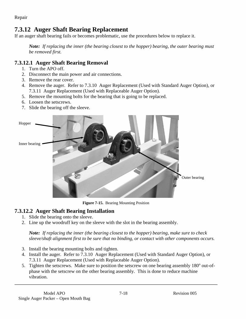
Repair
Model APO
Single Auger Packer – Open Mouth Bag 7-18 Revision 005
7.3.12 Auger Shaft Bearing Replacement If an auger shaft bearing fails or becomes problematic, use the procedures below to replace it.
Note: If replacing the inner (the bearing closest to the hopper) bearing, the outer bearing must be removed first.
7.3.12.1 Auger Shaft Bearing Removal 1. Turn the APO off. 2. Disconnect the main power and air connections. 3. Remove the rear cover. 4. Remove the auger. Refer to 7.3.10 Auger Replacement (Used with Standard Auger Option), or
7.3.11 Auger Replacement (Used with Replaceable Auger Option). 5. Remove the mounting bolts for the bearing that is going to be replaced. 6. Loosen the setscrews. 7. Slide the bearing off the sleeve.
Figure 7-15. Bearing Mounting Position
7.3.12.2 Auger Shaft Bearing Installation 1. Slide the bearing onto the sleeve. 2. Line up the woodruff key on the sleeve with the slot in the bearing assembly.
Note: If replacing the inner (the bearing closest to the hopper) bearing, make sure to check sleeve/shaft alignment first to be sure that no binding, or contact with other components occurs.
3. Install the bearing mounting bolts and tighten. 4. Install the auger. Refer to 7.3.10 Auger Replacement (Used with Standard Auger Option), or
7.3.11 Auger Replacement (Used with Replaceable Auger Option). 5. Tighten the setscrews. Make sure to position the setscrew on one bearing assembly 180 out-of-
phase with the setscrew on the other bearing assembly. This is done to reduce machine vibration.
Hopper
Inner bearing
Outer bearing

Repair
Revision 005 7-19 Model APO
Single Auger Packer – Open Mouth Bag
Figure 7-16. Bearing Setscrews, 180° Out-Of-Phase
6. Install the rear cover. 7. Connect the APO main power and air connections. 8. Check the APO for proper operation.
Mounting rails
Bearing assemblies
Setscrew
Setscrew
Grease zerk fitting
Grease zerk fitting
Auger shaft
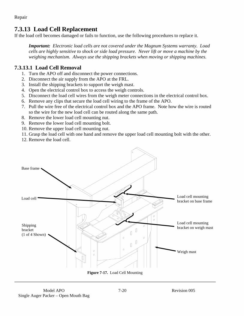
Repair
Model APO
Single Auger Packer – Open Mouth Bag 7-20 Revision 005
7.3.13 Load Cell Replacement If the load cell becomes damaged or fails to function, use the following procedures to replace it.
Important: Electronic load cells are not covered under the Magnum Systems warranty. Load cells are highly sensitive to shock or side load pressure. Never lift or move a machine by the weighing mechanism. Always use the shipping brackets when moving or shipping machines.
7.3.13.1 Load Cell Removal 1. Turn the APO off and disconnect the power connections. 2. Disconnect the air supply from the APO at the FRL. 3. Install the shipping brackets to support the weigh mast. 4. Open the electrical control box to access the weigh controls. 5. Disconnect the load cell wires from the weigh meter connections in the electrical control box. 6. Remove any clips that secure the load cell wiring to the frame of the APO. 7. Pull the wire free of the electrical control box and the APO frame. Note how the wire is routed
so the wire for the new load cell can be routed along the same path. 8. Remove the lower load cell mounting nut. 9. Remove the lower load cell mounting bolt. 10. Remove the upper load cell mounting nut. 11. Grasp the load cell with one hand and remove the upper load cell mounting bolt with the other. 12. Remove the load cell.
Figure 7-17. Load Cell Mounting
Shipping bracket (1 of 4 Shown)
Base frame
Load cell mounting bracket on base frame
Load cell mounting bracket on weigh mast
Weigh mast
Load cell
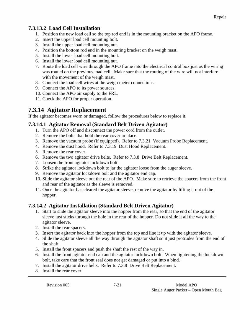
Repair
Revision 005 7-21 Model APO
Single Auger Packer – Open Mouth Bag
7.3.13.2 Load Cell Installation 1. Position the new load cell so the top rod end is in the mounting bracket on the APO frame. 2. Insert the upper load cell mounting bolt. 3. Install the upper load cell mounting nut. 4. Position the bottom rod end in the mounting bracket on the weigh mast. 5. Install the lower load cell mounting bolt. 6. Install the lower load cell mounting nut. 7. Route the load cell wire through the APO frame into the electrical control box just as the wiring
was routed on the previous load cell. Make sure that the routing of the wire will not interfere with the movement of the weigh mast.
8. Connect the load cell wires at the weigh meter connections. 9. Connect the APO to its power sources. 10. Connect the APO air supply to the FRL. 11. Check the APO for proper operation.
7.3.14 Agitator Replacement If the agitator becomes worn or damaged, follow the procedures below to replace it.
7.3.14.1 Agitator Removal (Standard Belt Driven Agitator) 1. Turn the APO off and disconnect the power cord from the outlet. 2. Remove the bolts that hold the rear cover in place. 3. Remove the vacuum probe (if equipped). Refer to 7.3.21 Vacuum Probe Replacement. 4. Remove the dust hood. Refer to 7.3.19 Dust Hood Replacement. 5. Remove the rear cover. 6. Remove the two agitator drive belts. Refer to 7.3.8 Drive Belt Replacement. 7. Loosen the front agitator lockdown bolt. 8. Strike the agitator lockdown bolt to jar the agitator loose from the auger sleeve. 9. Remove the agitator lockdown bolt and the agitator end cap. 10. Slide the agitator sleeve out the rear of the APO. Make sure to retrieve the spacers from the front
and rear of the agitator as the sleeve is removed. 11. Once the agitator has cleared the agitator sleeve, remove the agitator by lifting it out of the
hopper.
7.3.14.2 Agitator Installation (Standard Belt Driven Agitator) 1. Start to slide the agitator sleeve into the hopper from the rear, so that the end of the agitator
sleeve just sticks through the hole in the rear of the hopper. Do not slide it all the way to the agitator sleeve.
2. Install the rear spacers. 3. Insert the agitator back into the hopper from the top and line it up with the agitator sleeve. 4. Slide the agitator sleeve all the way through the agitator shaft so it just protrudes from the end of
the shaft. 5. Install the front spacers and push the shaft the rest of the way in. 6. Install the front agitator end cap and the agitator lockdown bolt. When tightening the lockdown
bolt, take care that the front seal does not get damaged or put into a bind. 7. Install the agitator drive belts. Refer to 7.3.8 Drive Belt Replacement. 8. Install the rear cover.
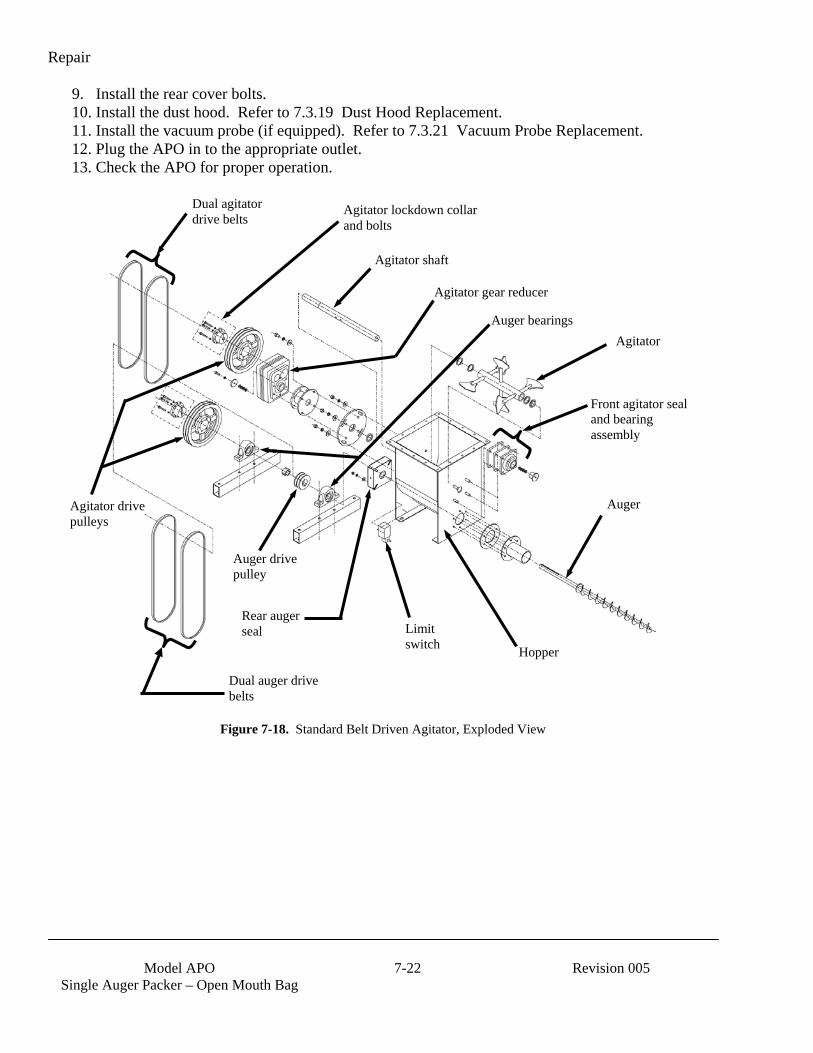
Repair
Model APO
Single Auger Packer – Open Mouth Bag 7-22 Revision 005
9. Install the rear cover bolts. 10. Install the dust hood. Refer to 7.3.19 Dust Hood Replacement. 11. Install the vacuum probe (if equipped). Refer to 7.3.21 Vacuum Probe Replacement. 12. Plug the APO in to the appropriate outlet. 13. Check the APO for proper operation.
Figure 7-18. Standard Belt Driven Agitator, Exploded View
Agitator lockdown collar and bolts
Agitator shaft
Agitator
Front agitator seal and bearing assembly
Agitator drive pulleys
Dual agitator drive belts
Rear auger seal
Hopper
Auger
Dual auger drive belts
Auger drive pulley
Auger bearings
Agitator gear reducer
Limit switch

Repair
Revision 005 7-23 Model APO
Single Auger Packer – Open Mouth Bag
7.3.14.3 Agitator Removal (Optional Electric Agitator) 1. Turn the APO off and disconnect the power cord from the outlet. 2. Remove the bolts that hold the rear cover in place. 3. Remove the rear cover. 4. Loosen the purge seal clamp by turning the clamp screw 2 complete turns counter-clockwise. 5. Loosen the agitator lockdown bolt. 6. Strike the agitator lockdown bolt to jar the auger loose from the auger sleeve. 7. Remove the agitator lockdown bolt and the auger end cap. 8. Slide the agitator toward the front of the APO. 9. Once the agitator has cleared the agitator sleeve, remove the purge seal from the agitator. 10. Pull the agitator out of the top of the APO.
7.3.14.4 Agitator Installation (Optional Electric Agitator) 1. Insert the agitator back into the APO from the top. 2. Slide the agitator toward the back of the APO, so that the end of the agitator shaft just sticks
through the hole in the rear of the hopper. Do not slide it all the way to the agitator sleeve. 3. Install the Purge Seal. Refer to 7.3.9 Purge Seal Replacement. 4. Slide the agitator all the way in and onto the agitator sleeve. 5. Install the agitator end cap and the agitator lockdown bolt. When tightening the lockdown bolt,
take care that the new seal does not get damaged or put into a bind. 6. Install the purge seal. Refer to 7.3.9 Purge Seal Replacement. 7. Install the rear cover. 8. Install the rear cover bolts. 9. Plug the APO in to the appropriate outlet. 10. Check the APO for proper operation.
Figure 7-19. Optional Electric Agitator Assembly, Exploded View
Agitator lockdown bolt
Agitator sleeve
Agitator
Upper hopper
Agitator drive motor

Repair
Model APO
Single Auger Packer – Open Mouth Bag 7-24 Revision 005
7.3.15 Flow Gate Replacement If the flow gate becomes worn or damaged, follow the procedures below to replace it.
7.3.15.1 Flow Gate Removal 1. Shut the APO off and disconnect the two main power connections. 2. Disconnect the main air supply at the FRL. 3. Remove the vacuum probe (if equipped). Refer to 7.3.21 Vacuum Probe Replacement. 4. Remove the dust hood. Refer to 7.3.19 Dust Hood Replacement. 5. Remove the flow gate to flow gate hinge nuts and washers. 6. Open the hinge and remove the flow gate.
Figure 7-20. Flow Gate Components, Exploded View
7.3.15.2 Flow Gate Installation 1. Open the flow gate hinge and position the flow gate so the two mounting studs protrude through
the bolt holes in the hinge. 2. Install the washers and flow gate mounting nuts. 3. Install the dust hood. Refer to 7.3.19 Dust Hood Replacement. 4. Install the vacuum probe (if equipped). Refer to 7.3.21 Vacuum Probe Replacement. 5. Connect the main air supply to the APO at the FRL. 6. Connect the two main power connections. 7. Turn the APO on and test for proper operation.
Dust ring retainer
Flow gate cylinder mount
Flow gate mount
Flow gate cylinder
Flow gate
Flow gate hinge
Auger
Repair
Revision 005 7-25 Model APO
Single Auger Packer – Open Mouth Bag
7.3.16 Flow Gate Hinge Replacement If the flow gate hinge becomes worn or damaged, follow the procedures below to replace it.
7.3.16.1 Flow Gate Hinge Removal 1. Shut the APO off and disconnect the two main power connections. 2. Disconnect the main air supply at the FRL. 3. Remove the vacuum probe (if equipped). Refer to 7.3.21 Vacuum Probe Replacement. 4. Remove the dust hood. Refer to 7.3.19 Dust Hood Replacement. 5. Disconnect the flow gate cylinder from the flow gate hinge. Refer to 7.3.17 Flow Gate Cylinder
Replacement. 6. Remove the flow gate. Refer to 7.3.15 Flow Gate Replacement. 7. Remove the flow gate hinge to flow gate mount nut and bolt. 8. Remove the flow gate hinge.
Figure 7-21. Flow Gate Hinge
7.3.16.2 Flow Gate Hinge Installation 1. Position the flow gate hinge in the flow gate mount so the bolt holes are lined up. 2. Install the flow gate hinge bolt and nut. 3. Install the flow gate. Refer to 7.3.15 Flow Gate Replacement. 4. Connect the flow gate cylinder to the flow gate hinge. Refer to 7.3.17 Flow Gate Cylinder
Replacement. 5. Install the dust hood. Refer to 7.3.19 Dust Hood Replacement. 6. Install the vacuum probe (if equipped). Refer to 7.3.21 Vacuum Probe Replacement. 7. Connect the main air supply line to the FRL. 8. Connect the two main power connections. 9. Turn the APO on and test for proper operation.
Flow gate mount
Flow gate
Flow gate hinge

Repair
Model APO
Single Auger Packer – Open Mouth Bag 7-26 Revision 005
7.3.17 Flow Gate Cylinder Replacement If the flow gate cylinder becomes damaged or develops a leak, follow the procedures below to replace it.
7.3.17.1 Flow Gate Cylinder Removal 1. Shut the APO off and disconnect the two main power connections. 2. Disconnect the main air supply at the FRL. 3. Remove the vacuum probe (if equipped). Refer to 7.3.21 Vacuum Probe Replacement. 4. Remove the dust hood. Refer to 7.3.19 Dust Hood Replacement. 5. Disconnect the air line at the flow gate cylinder. Press in on the quick connect fitting ring and
hold it in. Pull on the air line while holding the ring in. 6. Remove the flow gate cylinder to flow gate hinge nut and bolt. 7. Remove the flow gate cylinder to flow gate cylinder mount nut and bolt. 8. Remove the flow gate cylinder.
7.3.17.2 Flow Gate Cylinder Installation 1. Position the flow gate cylinder so that the mount on the cylinder end is in the flow gate cylinder
mount, and the rod end on the end of the shaft is in the flow gate hinge mount. 2. Install the flow gate cylinder to flow gate cylinder mount bolt and nut. 3. Install the flow gate cylinder to flow gate hinge bolt and nut. 4. Connect the flow gate cylinder air line. Make sure the end of the line is cut square. Press in on
the ring on the quick connect fitting and hold it in. Insert the end of the air line into the fitting and push it in as far as it will go. Release the ring.
5. Connect the main air supply line and check for leaks at the flow gate cylinder air fitting. If leaks are found, disconnect the main air supply. Disconnect the air line at the flow gate cylinder. Trim the end of the air line, making sure to make a square cut. Reconnect the line and check for leaks again. Repeat until no leak is present.
6. Install the dust hood. Refer to 7.3.19 Dust Hood Replacement. 7. Install the vacuum probe (if equipped). Refer to 7.3.21 Vacuum Probe Replacement. 8. Connect the two main power connections. 9. Turn the APO on and test for proper operation.
7.3.18 Transition Replacement If the transition becomes damaged, or needs to be removed to facilitate the removal of other components, follow these procedures for removal and installation.
7.3.18.1 Transition Removal 1. Shut the APO off and disconnect the two main power connections. 2. Disconnect the main air supply at the FRL. 3. Remove the vacuum probe (if equipped). Refer to 7.3.21 Vacuum Probe Replacement. 4. Remove the dust hood. Refer to 7.3.19 Dust Hood Replacement. 5. Remove the flow gate cylinder. Refer to 7.3.17 Flow Gate Cylinder Replacement. 6. Remove the flow gate. Refer to 7.3.15 Flow Gate Replacement. 7. Remove the nuts, washers, and bolts that secure the transition to the spout. 8. Remove the four transition mounting nuts and washers.
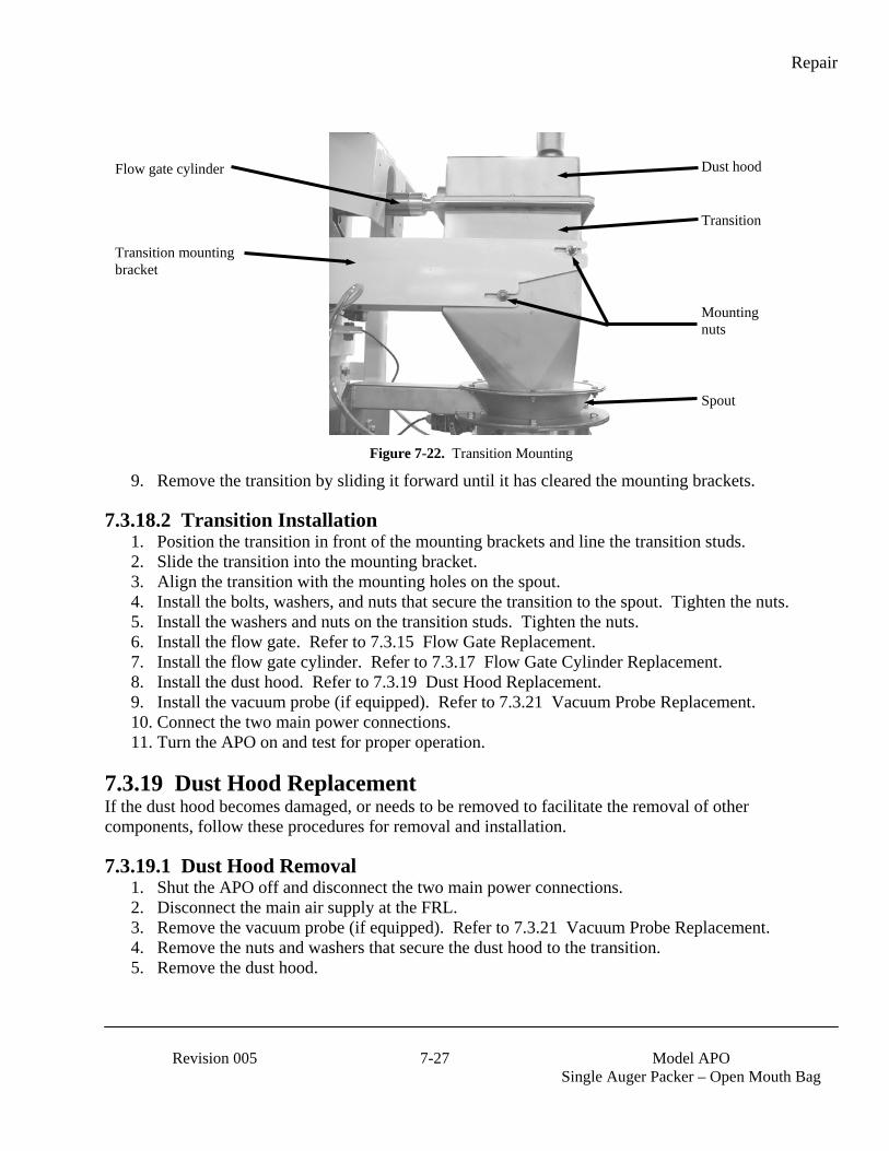
Repair
Revision 005 7-27 Model APO
Single Auger Packer – Open Mouth Bag
Figure 7-22. Transition Mounting
9. Remove the transition by sliding it forward until it has cleared the mounting brackets.
7.3.18.2 Transition Installation 1. Position the transition in front of the mounting brackets and line the transition studs. 2. Slide the transition into the mounting bracket. 3. Align the transition with the mounting holes on the spout. 4. Install the bolts, washers, and nuts that secure the transition to the spout. Tighten the nuts. 5. Install the washers and nuts on the transition studs. Tighten the nuts. 6. Install the flow gate. Refer to 7.3.15 Flow Gate Replacement. 7. Install the flow gate cylinder. Refer to 7.3.17 Flow Gate Cylinder Replacement. 8. Install the dust hood. Refer to 7.3.19 Dust Hood Replacement. 9. Install the vacuum probe (if equipped). Refer to 7.3.21 Vacuum Probe Replacement. 10. Connect the two main power connections. 11. Turn the APO on and test for proper operation.
7.3.19 Dust Hood Replacement If the dust hood becomes damaged, or needs to be removed to facilitate the removal of other components, follow these procedures for removal and installation.
7.3.19.1 Dust Hood Removal 1. Shut the APO off and disconnect the two main power connections. 2. Disconnect the main air supply at the FRL. 3. Remove the vacuum probe (if equipped). Refer to 7.3.21 Vacuum Probe Replacement. 4. Remove the nuts and washers that secure the dust hood to the transition. 5. Remove the dust hood.
Transition mounting bracket
Spout
Flow gate cylinder Dust hood
Mounting nuts
Transition

Repair
Model APO
Single Auger Packer – Open Mouth Bag 7-28 Revision 005
Figure 7-23. Mounting The Dust Hood On The Transition
7.3.19.2 Dust Hood Installation 1. Position the dust hood above the transition and line up the holes in the dust hood with the studs
on the transition. 2. Lower the dust hood onto the transition so the mounting studs protrude through the holes in the
dust hood. 3. Install the washers and nuts on the studs. 4. Adjust the dust hood on the transition so that the edges are flush with the edges of the transition. 5. Tighten the dust hood mounting nuts. 6. Install the vacuum probe (if equipped). Refer to 7.3.21 Vacuum Probe Replacement. 7. Connect the two main power connections. 8. Turn the APO on and test for proper operation.
Transition
Dust hood
Dust hood mounting studs
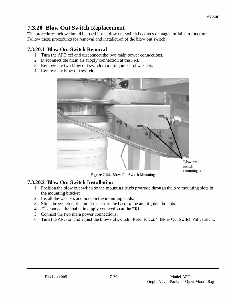
Repair
Revision 005 7-29 Model APO
Single Auger Packer – Open Mouth Bag
7.3.20 Blow Out Switch Replacement The procedures below should be used if the blow out switch becomes damaged or fails to function. Follow these procedures for removal and installation of the blow out switch.
7.3.20.1 Blow Out Switch Removal 1. Turn the APO off and disconnect the two main power connections. 2. Disconnect the main air supply connection at the FRL. 3. Remove the two blow out switch mounting nuts and washers. 4. Remove the blow out switch.
Figure 7-24. Blow Out Switch Mounting
7.3.20.2 Blow Out Switch Installation 1. Position the blow out switch so the mounting studs protrude through the two mounting slots in
the mounting bracket. 2. Install the washers and nuts on the mounting studs. 3. Slide the switch to the point closest to the base frame and tighten the nuts. 4. Disconnect the main air supply connection at the FRL. 5. Connect the two main power connections. 6. Turn the APO on and adjust the blow out switch. Refer to 7.2.4 Blow Out Switch Adjustment.
Blow out switch mounting nuts
Repair
Model APO
Single Auger Packer – Open Mouth Bag 7-30 Revision 005
7.3.21 Vacuum Probe Replacement If the vacuum probe becomes damaged, or needs to be removed to facilitate the removal of other components, follow these procedures for removal and installation.
7.3.21.1 Vacuum Probe Removal 1. Remove the gauge from the front of the vacuum pump. 2. Remove the plug from the front hole on the left side of the vacuum pump. 3. Remove the top 3/8” blue hose from the pilot on the 56C-57-RA solenoid. 4. Disconnect a 3/8” blue hose on both bottom and top fittings. 5. Remove the 3/8” brass tee from the top and bottom 3/8” fittings. 6. Remove the brass tee from the vacuum pump screw, at the rear port on the left side. 7. Remove the 3/8” npt plug from the #3 port on the 55B-11-RA solenoid. 8. Disconnect the ½” blue hose from the ½” straight fitting. 9. On the solenoid 55B-11-RA, remove the from the 3/8” red hose that connects the #1 port to the
B port on the solenoid valve stack on the rear of the machine labeled probe. 10. Disconnect the 3/8” red air hose from the pilot on the 55B-11-RA solenoid and the 3/8” running
tee hose fitting in #1 port on the 55B-11-RA solenoid. 11. Remove the 3/8” x 1/8” hose running tee from the #1 port of 55B-11-RA solenoid. 12. Remove the 3/8” x 1/8” tee from the #2 port on the left side of 55B-11-RA solenoid. 13. Remove the ½” straight hose fitting from the bottom of the tee. 14. Remove the ½” brass running tee from the nipple in the #1 port on the 56C solenoid valve. 15. Remove the ½” galvanized NPT nipple from the reducer in the #1 port on the 56C solenoid
valve. 16. Remove the ¾” x 1/8” reducer from the #1 port on the 56C solenoid valve. 17. Remove the 2”x ½” galvanized nipple from the reducer in the #2 port of the 56C solenoid valve. 18. Remove the ¾” x ½” galvanized reducer from the #2 port of the 56C solenoid valve. 19. Remove the solenoid valve. 20. Remove the roller switch lever to the up and down switches. 21. Remove the t-handle in tapped hole on the rear side of the stop bracket. 22. Dismount the probe stop back bracket back plate from rear of stop bracket. 23. Remove the probe tips from the probes until they are tight and the sheath is compressed slightly. 24. Remove the sheath from the probe ends. 25. Dismount the switch stop bracket on band cylinder probe bracket. 26. Dismount the shock absorber and screw from the threaded probe stop bracket. 27. Dismount the limit switch from the switch bracket. 28. Remove the part probe stop bracket from the band cylinder flat bar. 29. Remove the probe switch bracket from the band cylinder flat bar. 30. Remove the probe bracket from the band cylinder. 31. Remove the band cylinder from the band cylinder flat bar bracket. 32. Remove the band cylinder flat bar bracket from the probe mast. 33. Remove the probe mast angle bracket from the probe mast on top. 34. Remove the probe mast from APO frame.
Repair
Revision 005 7-31 Model APO
Single Auger Packer – Open Mouth Bag
7.3.21.2 Vacuum Probe Installation 1. Bolt the probe mast to APO frame. 2. Bolt the probe mast angle bracket to the probe mast on top. 3. Bolt the band cylinder flat bar bracket to the probe mast. 4. Bolt the band cylinder to the band cylinder flat bar bracket. 5. Bolt the probe bracket to the band cylinder. 6. Bolt the probe switch bracket to the band cylinder flat bar. 7. Slide the part probe stop bracket onto the band cylinder flat bar. 8. Mount the limit switch on the switch bracket. 9. Mount the shock absorber and screw in threaded probe stop bracket. 10. Mount switch stop bracket on band cylinder probe bracket. 11. Slide the sheath on the probe ends. 12. Screw the probe tips on the probes until they are tight and the sheath is compressed slightly. 13. Mount the probe stop back bracket back plate to rear of stop bracket. 14. Screw t- handle in tapped hole on the rear side of the stop bracket. 15. Mount roller switch lever to the up and down switches. 16. Install the solenoid valve. 17. Install the ¾” x ½” galvanized reducer in the #2 port of the 56C solenoid valve. Make sure the
reducer is tight. 18. Install the 2”x ½” galvanized nipple into the reducer in the #2 port of the 56C solenoid valve.
Make sure the nipple is tight. 19. Install the ¾” x 1/8” reducer into the #1 port on the 56C solenoid valve. Make sure the reducer
is tight. 20. Install the ½” galvanized NPT nipple into the reducer in the #1 port on the 56C solenoid valve.
Make sure the nipple is tight. 21. Install the ½” brass running tee into the nipple in the #1 port on the 56C solenoid valve. 22. Install the ½” straight hose fitting on the bottom of the tee. 23. Install the 3/8” x 1/8” tee into the #2 port on the left side of 55B-11-RA solenoid. 24. Install the 3/8” x 1/8” hose running tee into the #1 port of 55B-11-RA solenoid. 25. Connect a 3/8” red air hose from the pilot on the 55B-11-RA solenoid to the 3/8” running tee
hose fitting in #1 port on the 55B-11-RA solenoid. 26. On the solenoid 55B-11-RA, from the #1 port, run a 3/8” red hose to the B port on the solenoid
valve stack on the rear of the machine labeled probe. 27. Connect ½” blue hose to the ½” straight fitting. 28. Install a 3/8” NPT plug into the #3 port on the 55B-11-RA solenoid. 29. Install a brass tee in the vacuum pump screw, in the rear port on the left side. 30. Install a 3/8” brass tee in the top and bottom 3/8” fittings. 31. Connect a 3/8” blue hose on both bottom and top fittings. 32. Run the bottom 3/8 blue hose to the valve. 33. Run the top 3/8” blue hose to the pilot on the 56C-57-RA solenoid. 34. Plug the front hole on the left side of the vacuum pump. 35. Install the gauge that comes with the vacuum pump in the front of the pump.
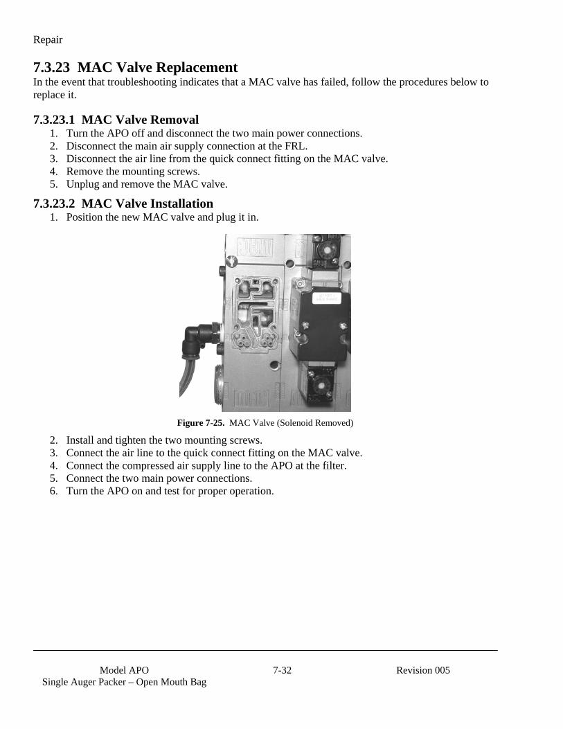
Repair
Model APO
Single Auger Packer – Open Mouth Bag 7-32 Revision 005
7.3.23 MAC Valve Replacement In the event that troubleshooting indicates that a MAC valve has failed, follow the procedures below to replace it.
7.3.23.1 MAC Valve Removal 1. Turn the APO off and disconnect the two main power connections. 2. Disconnect the main air supply connection at the FRL. 3. Disconnect the air line from the quick connect fitting on the MAC valve. 4. Remove the mounting screws. 5. Unplug and remove the MAC valve.
7.3.23.2 MAC Valve Installation 1. Position the new MAC valve and plug it in.
Figure 7-25. MAC Valve (Solenoid Removed)
2. Install and tighten the two mounting screws. 3. Connect the air line to the quick connect fitting on the MAC valve. 4. Connect the compressed air supply line to the APO at the filter. 5. Connect the two main power connections. 6. Turn the APO on and test for proper operation.
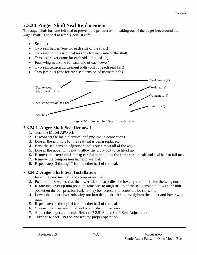
Repair
Revision 005 7-33 Model APO
Single Auger Packer – Open Mouth Bag
7.3.24 Auger Shaft Seal Replacement The auger shaft has one felt seal to prevent the product from leaking out of the auger box around the auger shaft. The seal assembly consists of:
• Seal box • Two seal halves (one for each side of the shaft) • Two seal compression halves (one for each side of the shaft) • Two seal covers (one for each side of the shaft) • Four wing nuts (one for each end of each cover) • Two seal tension adjustment bolts (one for each seal half) • Two jam nuts (one for each seal tension adjustment bolt).
Figure 7-26. Auger Shaft Seal, Exploded View
7.3.24.1 Auger Shaft Seal Removal 1. Turn the Model APO off. 2. Disconnect the main electrical and pneumatic connections. 3. Loosen the jam nuts for the seal that is being replaced. 4. Back the seal tension adjustment bolts out almost all of the way. 5. Loosen the upper wing nut to allow the pivot bolt to be tilted up. 6. Remove the cover while being careful to not allow the compression half and seal half to fall out. 7. Remove the compression half and seal half. 8. Repeat steps 3 through 7 for the other half of the seal.
7.3.24.2 Auger Shaft Seal Installation 1. Insert the new seal half and compression half. 2. Position the cover so that the lower tab slot straddles the lower pivot bolt inside the wing nut. 3. Rotate the cover up into position, take care to align the tip of the seal tension bolt with the bolt
pocket on the compression half. It may be necessary to screw the bolt in some. 4. Lower the upper pivot bolt/wing nut into the upper tab slot and tighten the upper and lower wing
nuts. 5. Repeat steps 1 through 4 for the other half of the seal. 6. Connect the main electrical and pneumatic connections. 7. Adjust the auger shaft seal. Refer to 7.2.5 Auger Shaft Seal Adjustment. 8. Turn the Model APO on and test for proper operation.
Seal box
Seal compression half (2)
Wing nuts (4)
Seal half (2)
Seal covers (2)
Seal tension adjustment bolt (2)
Jam nut (2)
Repair
Model APO
Single Auger Packer – Open Mouth Bag 7-34 Revision 005
This Page Intentionally Left Blank

Glossary
Revision 005 Glossary-1 Model APO
Single Auger Packer – Open Mouth Bag
Glossary TERM DEFINITION AC Alternating Current Agitator A type of mixer that is used inside the hopper to help prevent product bridging. The agitator can be
belt driven or can be driven by an electric motor. Audible alarm The sounding of a bell, buzzer, beeper, or other acoustic device to draw the attention of the operator
to a system fault. Auger A screw-type device that is used to feed the product from the supply hopper to the discharge spout. Bag settler A device that is used to help the product to settle in the bottom of the bag. Settlers can be either
vibratory or lift and drop type. Bag tilt A pneumatic device that is used to tilt the filled bag forward off of the spout to allow the operator to
tuck the sleeve. Bagging cycle A series of functions that describe the packaging process, from beginning to end, for one package of
product. Base frame The portion of the machine that provides the support structure for all other components that make up
the machine. Bridging A condition where an air pocket develops inside the hopper under the product and interrupts the
flow of the product to the feed device. Bulk rate The fill speed used to package the largest portion of the product. It is a fast fill speed. Also referred
to as Fast A. Component An item of hardware as commonly supplied complete by manufacturers. Contact A conducting part that co-acts with another conducting part to open or close an electrical circuit. Counter A device that counts the occurrence of some event. Cubic Feet/Minute (CFM)
A unit of measure that is used to describe the amount of compressed air that is used by a machine.
DC Direct Current De-energize To deprive an electro-receptive device of its operating current. Dribble rate The fill speed used to package the smallest portion of the product. It is a slow fill speed, as
compared to the bulk rate. Also referred to as Slow A. Dual set point (DSP) Refers to a machine that has the capability of delivering the product at two different fill speeds. ESD Electrostatic Discharge Failure The event, or inoperable state, in which any item or part of an item does not, or would not, perform
as specified. Fast A Setting that controls the auger speed during the bulk fill operation. Fault Violation of an operating system rule. Faults are minor or major; many major faults are not usually
recoverable, even with fault routines. Fill rate A general term used to describe the speed at which the product is being fed. Filter/Regulator/ Lubricator (FRL)
A combination device that filters the incoming compressed air to remove contaminants and moisture. This device also provides the operator with the ability to regulate how much air pressure is available at the outlet. A lubricator is also included. The lubricator provides a reservoir that is filled with a special oil to help lubricate the internal components of the downstream pneumatic devices.
Fine dribble rate On some units, a third feed rate is available. This speed is slower than the dribble rate and is used to create very precise weighments.
Glossary
Model APO
Single Auger Packer – Open Mouth Bag Glossary-2 Revision 005
TERM DEFINITION Ground/GND A conducting connection, whether intentional or accidental, between an electrical circuit or
equipment and the earth, or some other conducting body at a reference potential. I/O Input/Output IN, in. inch or inches kg Kilogram lb or lbs Pound or pounds LCD Liquid crystal display. This is the type of screen used on the T4000 and T3000 control panels. LED Light emitting diode. Used as status indicator for many types of equipment (processors, power
supplies, I/O modules, modems, etc). Load cell An electronic device that is used to monitor the weight of the product that is being packaged. MAC valve A pneumatic valve that is used for controlling various pneumatic cylinders. The valves apply air
pressure to the cylinders causing them to either open or close. Module Assembly of components, which function as a unit and can be replaced as a unit. OPC OLE for Process Control PLC Programmable Logic Controller. Used to monitor inputs from specific devices, analyze those inputs
using built in software, and to control output devices based on the results of the software analysis. Pounds per Square Inch (PSI)
Unit of measured used to describe air pressure.
POWER ON indicator
A lamp that will illuminate when power has been turned on.
Power supply A device that converts available power to a form that a system can use — usually converts AC power to DC power.
Processor The decision-making and data storage sections of a programmable controller or computer. Product Refers to the material that is being packaged by the machine. Purge kit Optional device that is used to prevent combustible dust accumulation or to prevent or remove
flammable gas/vapor build up. Reaction time The time used by equipment, operator, or both, that elapses between the moments an action is called
for and when the desired result occurs. Refrigerated air dryer
A device that is uses a refrigeration unit to remove moisture from a compressed air supply. This is done to reduce corrosion and contamination of the pneumatic equipment.
Relay An electromagnetic device that is operated by a variation in the conditions of one electric circuit, to effect the operation of other devices in the same or another electric circuit.
RS–232 An EIA standard that specifies electrical, mechanical, and functional characteristics for serial binary communication circuits. A single–ended serial communication interface.
Safety-critical Any condition, event, operation, process, component, assembly, subsystem, or system, the failure or malfunction of which can result in severe injury, severe occupational illness, or major damage.
Set point A control setting that is used to define a transition point in the fill process. It can be a point when a change in fill rate occurs, or when the machine stops filling all together.
Set point 1 (SP1) The control setting that defines where the bulk feed rate is to stop. Set point 2 (SP2) The control setting that defines where the dribble rate stops. Is typically slightly lower than target
weight. Shipping bracket A piece of metal that is used to secure the weighing apparatus to the base frame during shipping to
prevent damage to the weighing apparatus. Single set point (SSP)
Refers to a machine that has the capability of delivering the product at a single fill speeds.

Glossary
Revision 005 Glossary-3 Model APO
Single Auger Packer – Open Mouth Bag
TERM DEFINITION Slow A Setting that controls the auger speed during the dribble fill operation. STOP button/indicator
Used by the operator to immediately stop the machine. Is a large red button that will illuminate when the stop button has been pressed. The machine will not start again until the button has pulled out.
Surge A sudden rise of current or voltage. Surge hopper A reservoir where product is stored for packaging. T4000 An electronic control panel that was jointly developed by Magnum Systems and Hardy Instruments.
This control panel is standard control panel on the APO. T3000 An electronic control device that was jointly developed by Magnum Systems and Hardy
Instruments. This control panel is available as an option on the APO. Target weight The desired package weight. VAC Volt, alternating current VDC Volt, direct current Water separator A device that is installed in a compressed air supply line to remove excess moisture from the air
supply. This is done to reduce corrosion and contamination of the pneumatic equipment. Weighment One charge or fill of a packaging machine. VOM Volt-Ohm Meter Weight display An electronic device that is used to display package weights and to set package parameters.
Glossary
Model APO
Single Auger Packer – Open Mouth Bag Glossary-4 Revision 005
This Page Intentionally Left Blank
Index
Revision 005 Index-1 Model APO
Single Auger Packer – Open Mouth Bag
Index Agitator, ........................................................ 1-5 Agitator Replacement, ................................ 7-21 Air Filter/Regulator/Lubricator (FRL)
Replacement, ........................................... 7-11 Air Fitting Replacement, ............................. 7-10 Air Pressure Adjustment, .............................. 7-1 Air Supply Line Replacement, .................... 7-10 Allen-Bradley MicroLogixTM 1000, ............. 4-5 Allen-Bradley PanelView 300, ............ 1-13, 4-6 Allen-Bradley Programmable Logic Controller (PLC), .................................... 1-13 Auger Replacement (Used with Replaceable Auger Option), .................... 7-17 Auger Replacement (Used with Standard Auger Option), ......................... 7-16 Auger Shaft Bearing Replacement, ............. 7-18 Auger Shaft Seal Adjustment, ....................... 7-3 Auger Shaft Seal Replacement, .................. 7-33 Auger Shaft Seals, ......................................... 1-6 Bag Settlers, .................................................. 1-5 Base Frame, ................................................... 1-2 Blow Out Switch, .......................................... 1-4 Blow Out Switch Adjustment, ...................... 7-3 Blow Out Switch Replacement, .................. 7-29 Calibrating The T3000 Control Panel
(Optional), ............................................... 3-13 Calibrating The T4000 Control Panel, ........ 3-10 Calibration, .................................................... 3-7 Check All Fasteners, ..................................... 5-2 Check Calibration, ........................................ 5-1 Cleaning, ....................................................... 5-1 Component Replacement Procedures, .......... 7-4 Daily Maintenance Procedures, .................... 5-1 Drain Water From the Water Separator, ....... 5-1 Drive Belt Replacement, ............................. 7-13 Drive Motor, ................................................. 1-4 Dust Hood, .................................................... 1-8 Dust Hood Replacement, ............................ 7-27 Electrical Connections, ................................. 3-1 Electrical Requirements, ............................... 1-1 Electro Static Discharge, .................................. ii Electro-static Discharge (ESD) Prevention Procedures, ................................ ii Entering Numbers Using The T4000 Control Panel, ........................................... 4-3
Establishing System Security Settings, ......... 3-3 Felt Seals, ...................................................... 1-7 Field Service, .................................................. iii Flex Leaf Replacement, .............................. 7-12 Flex Leaves, .................................................. 1-5 Flow Gate Cylinder Replacement, .............. 7-26 Flow Gate Hinge Replacement, .................. 7-25 Flow Gate Replacement, ............................. 7-24 General Fill Cycle Information, .................... 4-1 Glossary, ....................................................... 7-1 Hopper, .......................................................... 1-7 Important/Notable Information, ....................... ii Inflatable Neck Seal Pressure Switch, .......... 1-4 Inflatable Neck Seal Pressure Switch
Adjustment, ............................................... 7-2 Inflatable Neck Seal Replacement, ............... 7-6 Initial Setup, ................................................ 4-13 Load Cell, ...................................................... 1-3 Load Cell Replacement, .............................. 7-20 MAC Valve Replacement, .......................... 7-32 Machine Controls, ......................................... 1-9 Major Systems and Components, ................. 1-2 Making System Adjustments With the PV300 Control Panel, ....................... 4-10 Manual Controls and Indications, ................. 1-9 Manual Scope, ............................................... 1-1 Mechanical Setup, ......................................... 3-1 Monthly Maintenance, .................................. 5-2 Network Connections, ................................... 3-2 Open Mouth Bag Spout, ............................... 1-4 Operation, ...................................................... 4-1 Operational Controls, .................................... 4-2 Personal Safety Instructions, ............................ ii PLC Error Messages, .................................... 6-6 Pneumatic Connections, ................................ 3-1 Pneumatic Requirements, ............................. 1-1 Power Control Box, .................................... 1-14 Preventive Maintenance, ............................... 5-1 Product Description, ..................................... 1-1 Purge Kit, .................................................... 1-15 Purge Kit Maintenance, ................................ 5-2 Purge Kit Troubleshooting, ........................... 6-6 Purge Seal Adjustment/Calibration, .............. 7-2 Purge Seal Replacement, ............................ 7-14 Purge Seals, ................................................... 1-6

Index
Model APO
Single Auger Packer – Open Mouth Bag Index - 2 Revision 005
PV300 Menus, ............................................... 4-6 Rear Cover, ................................................... 1-5 Receiving Equipment, ................................... 2-1 Repair and Adjustment, ................................ 7-1 Setting Up a Dual Set Point APO with T4000 Controls, .............................. 4-15 Setting Up a Single Set Point APO with T4000 Controls, .............................. 4-13 Setup/Installation, ......................................... 3-1 Spout Replacement, ...................................... 7-4 Starting the Unit, ......................................... 4-11 Surge Hopper, ............................................... 1-7 System Adjustment Procedures, ................... 7-1 System Alarms, .............................................. 6-5 T3000, ........................................................... 3-2 T3000 Alarms, .............................................. 6-6 T3000 Controls, ................................... 1-11, 4-4 T3000 Security Settings, ............................... 3-6 T4000 Alarms, .............................................. 6-5
T4000 Control Panel, .................................... 3-9 T4000 Controls, ................................... 1-10, 4-2 T4000 Dual Set Point (DSP) Setup, .............. 4-3 T4000 Pre-Calibration Procedures, ............... 3-9 T4000 Security Settings, ............................... 3-3 T4000 Single Set Point (SSP) Setup, ............ 4-3 Timer Adjustments, ....................................... 7-3 Transition, ..................................................... 1-7 Transition Replacement, ............................. 7-26 Trouble Symptoms, ....................................... 6-1 Troubleshooting, ........................................... 6-1 Troubleshooting Process, .............................. 6-1 Uncrating the Equipment, ............................. 2-1 Using the T3000 to Set Points and Feeder
Speeds, .................................................... 4-17 Vacuum Probe Replacement, ...................... 7-30 Warranty Information, .................................... iii Weigh Mast, .................................................. 1-3
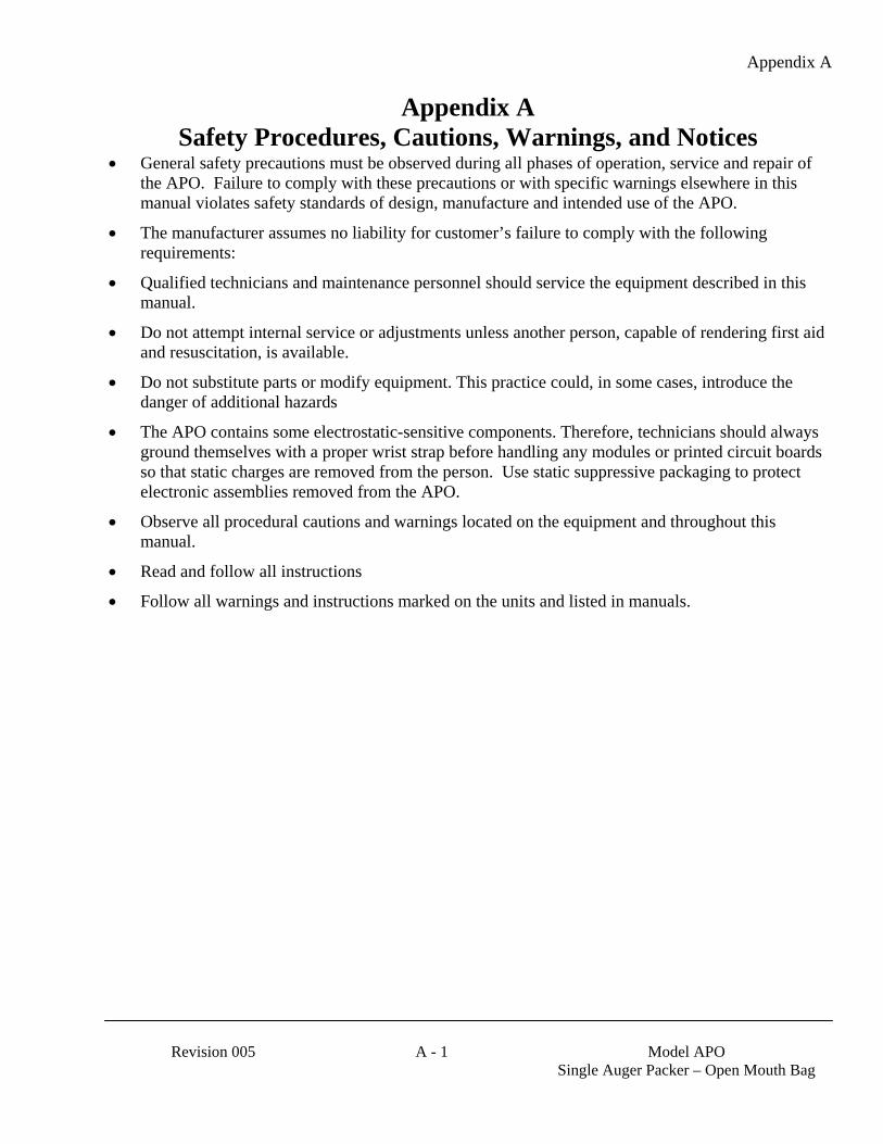
Appendix A
Revision 005 A - 1 Model APO
Single Auger Packer – Open Mouth Bag
Appendix A Safety Procedures, Cautions, Warnings, and Notices
• General safety precautions must be observed during all phases of operation, service and repair of the APO. Failure to comply with these precautions or with specific warnings elsewhere in this manual violates safety standards of design, manufacture and intended use of the APO.
• The manufacturer assumes no liability for customer’s failure to comply with the following requirements:
• Qualified technicians and maintenance personnel should service the equipment described in this manual.
• Do not attempt internal service or adjustments unless another person, capable of rendering first aid and resuscitation, is available.
• Do not substitute parts or modify equipment. This practice could, in some cases, introduce the danger of additional hazards
• The APO contains some electrostatic-sensitive components. Therefore, technicians should always ground themselves with a proper wrist strap before handling any modules or printed circuit boards so that static charges are removed from the person. Use static suppressive packaging to protect electronic assemblies removed from the APO.
• Observe all procedural cautions and warnings located on the equipment and throughout this manual.
• Read and follow all instructions
• Follow all warnings and instructions marked on the units and listed in manuals.

Appendix A
Model APO
Single Auger Packer – Open Mouth Bag A - 2 Revision 005
This Page Intentionally Left Blank
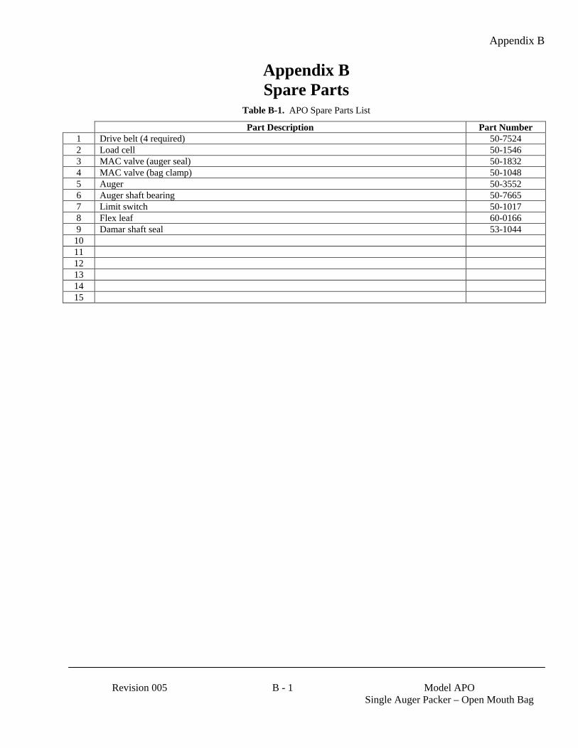
Appendix B
Revision 005 B - 1 Model APO
Single Auger Packer – Open Mouth Bag
Appendix B Spare Parts
Table B-1. APO Spare Parts List
Part Description Part Number 1 Drive belt (4 required) 50-7524 2 Load cell 50-1546 3 MAC valve (auger seal) 50-1832 4 MAC valve (bag clamp) 50-1048 5 Auger 50-3552 6 Auger shaft bearing 50-7665 7 Limit switch 50-1017 8 Flex leaf 60-0166 9 Damar shaft seal 53-1044
10 11 12 13 14 15

Appendix B
Model APO
Single Auger Packer – Open Mouth Bag B - 2 Revision 005
This Page Intentionally Left Blank
Appendix C
Revision 005 C - 1 Model APO
Single Auger Packer – Open Mouth Bag
Appendix C Mechanical Drawings
Table C-1. APO Mechanical Drawing List
Drawing Title Drawing Number 1 Model APO – Exploded View BDAPOM-ISO-00.dwg 2 Model APO – Exploded View BDAPOM-ISO-01.dwg 3 Model APO – Exploded View BDAPOM-ISO-02.dwg 4 5 6 7 8 9
10 11 12 13 14 15

Appendix C
Model APO
Single Auger Packer – Open Mouth Bag C - 2 Revision 005
This Page Intentionally Left Blank
Appendix D
Revision 005 D - 1 Model APO
Single Auger Packer – Open Mouth Bag
Appendix D Electrical Drawings
Table D-1. APO Electrical Drawing List
Drawing Title Drawing Number 1 2 3 4 5 6 7 8 9
10 11 12 13 14 15

Appendix D
Model APO
Single Auger Packer – Open Mouth Bag D - 2 Revision 005
This Page Intentionally Left Blank
Appendix E
Revision 005 E - 1 Model APO
Single Auger Packer – Open Mouth Bag
Appendix E Control Panel User Guide

Appendix E
Model APO
Single Auger Packer – Open Mouth Bag E - 2 Revision 005
This Page Intentionally Left Blank
Appendix F
Revision 005 F - 1 Model APO
Single Auger Packer – Open Mouth Bag
Appendix F Custom Features
The documents included in Appendix F will provide information regarding any custom features that were ordered and included in the equipment purchase.
Appendix F
Model APO
Single Auger Packer – Open Mouth Bag F - 2 Revision 005
This Page Intentionally Left Blank

Appendix F
Revision 005 F - 3 Model APO
Single Auger Packer – Open Mouth Bag
The equipment that accompanies this manual was not ordered with any custom features, thus no custom documentation is included.

Appendix F
Model APO
Single Auger Packer – Open Mouth Bag F - 4 Revision 005
This Page Intentionally Left Blank