Embed Size (px)
Citation preview
Simultaneous Linear and DeformableRegistration Through a Higher Order MRF
Model
Vivien Fecamp1,2, Aristeidis Sotiras3, and Nikos Paragios1,2
1 CVC, Ecole CentraleSupelec, France2 GALEN Team, INRIA Saclay vivien.fecamp,[email protected]
3 Section of Biomedical Image Analysis University of [email protected]
Abstract. In this paper, we present a new approach to tackle simul-taneously linear and deformable registration between a pair of images.Our combined formulation avoids the bias created when linear registra-tion is performed independently before a deformable registration. Ourregistration problem is formulated as a discrete Markov Random Fieldemploying a higher order objective function. To cope with both linearand deformable registration, we introduce two graphical models, one foreach subproblem. The two graphical models consist of identical node sys-tems. The nodes of the first graph encode the local translations of theglobal linear registration component, while the nodes of the second graphencode the local translations of the deformable registration component.A higher-order edge system (third and fourth order interactions) thatimposes the linearity of the transformation is introduced for the firstgraph, while a simple pairwise edge system that promotes the smooth-ness of the deformation field is employed for the second graph. The twographs are coupled by additional edges that connect homologous nodesand encode the data term, while unary potentials are used only for thedeformable part and penalize large deformations. The resulting formu-lation is modular with respect to the image metric used to evaluate thecorrectness of mapping as well as with respect to the nature of the lineartransformation (rigid, similarity, affine). Inference on this graph is per-formed efficiently through Alternating Direction Method of Multipliers.Promising results on medical 3D images demonstrate the potentials ofour approach.
Keywords: Registration, Markov Random Fields, Higher Order Potentials,Alternating Direction Method of Multipliers
1 Introduction
Linear [9] and deformable registration [7, 19] are among the computational pil-lars of medical image analysis. Linear methods aim to establish approximate
correspondences using global models (rigid, similarity, affine, etc.), whereas de-formable methods seek a one-to-one mapping between the images.
Linear registration is either geometric or iconic. On the one hand geometricmethods seek a global transformation that corresponds to the lowest potentialof the Euclidean distance between corresponding points. These methods arenot within the scope of the paper and therefore will not be reviewed. On theother hand, iconic methods aim to determine the set of parameters of a givenlinear transformation that minimizes an image-based objective function. Globalmethods adopt often standard similarity metrics like Sum of Absolute Differences(SAD), Normalized Cross Correlation (NCC), Sum of Squared Differences (SSD),Mutual information (MI) and determine the optimal transformation through agradient-driven optimization method. In order to cope with local minima andreduce the dependency on the initial conditions, optimization approaches likesimplex methods [17], cutting planes methods [11] or more recently discreteoptimization ones [22], have been investigated. Jenkinson et al. [9] uses a hybridscheme that combines both local and global search.
Once linear mapping has been addressed, deformable registration is used toprovide dense correspondences. These methods are in most of the cases image-based and one can refer to an important number of successful developments inthe recent years [19]. Without attempting to give a full overview of this richfield, let us note that most methods can be classified based on the optimiza-tion technique they employ. The first class of methods regroups registration ap-proaches that solve the problem by means of continuous optimization techniques.Typical examples of this class include the Demons algorithm [20] that iteratesbetween estimating correspondences and smoothing, Free-Form Deformations(FFD) registration [16] using gradient descent, and Advanced NormalizationTools (ANTS) [2]. The algorithm used in ELASTIX [10] is based on a B-splinedeformation model and is a good compromise between complexity and perfor-mance. The second class of registration methods consists of approaches thatquantize the solution space and use discrete optimization techniques. DROP[6] is a modular, metric free, computationally efficient approach to deformableregistration. DRAMMS [15] use MRF solvers while [3] uses random walker ap-proaches.
Linear and deformable registration have been considered separately up tonow. Deformable registration is usually built upon the result of the linear one.Therefore, one can expect that a bias is introduced in the deformable regis-tration by the linear transformation. Moreover, the performance of deformableregistration depends heavily on the input of the linear one and might fail to pro-vide appropriate correspondences. Coupling the two problems would remove thebias and by allowing them to share information better results may be achieved.To the best of our knowledge, only three previous works exist. Haber et al. [8]use continuous optimization which causes problems with the similarity criterion.Kwon et al. [14] introduce a curvature regularisation as a soft constraint andsolve the problem on the factor graph with the tree-reweighted algorithm butthere is no possible reconstruction of the rigid part of the transform. Their regu-
2
larisation is seen as a penalty to get a soft deformation field, and not to have anexact mathematical decomposition. Finally Ferrante et al. [5] presented a sim-ilar decomposition to perform 2D-3D registration, but with a soft higher orderconstraint again. In this paper, we solve the problem in the discrete case whichallows us to be modular with the metric space and the regularization constraint.
In this paper, we introduce a novel graphical model that consists of twointerconnected components and estimates simultaneously the two registrationcomponents by considering a local deformation approach. The first graph con-sists of a regular grid where higher order constraints between nodes impose theexpected nature of linearity of the transformation as defined in our previouswork [4]. The second graph - inspired by the one proposed in [6] - adopts anidentical grid endowed with singleton terms that penalize the magnitude of dis-placements and pairwise constraints imposing deformation smoothness. The twographs are interconnected and in these edges the exact data term is modeledthrough the composition of the two transformations. The resulting formulationcan deal with arbitrary types of linear mapping, arbitrary similarity criteriaand various regularization terms. The optimization of this graphical model isperformed through a master-slave framework that is based on the dual decom-position with the Alternating Direction Method of Multipliers (DD-ADMM)approach [1].
The remainder of the paper is organized as follows: Sect. 2 presents thegraphical model formulation for the linear mapping, that is endowed with thedeformable component. The optimization of the complete framework and theassociated implementation details are presented in Sect. 2.3. Sec 3 presents im-plementation details and experimental validation. The last section concludes thepaper and provides future directions.
2 Method
The registration problem consists in finding a transformation T that aligns animage J (typically referred to as source) to a reference image I (typically re-ferred to as target). A common approach for modeling this problem is by energyminimization:
T = arg minT
ξ (I, J ◦ T ) , (1)
where T is the optimal transformation and ξ is a similarity measure. Our pur-pose is to model the image transformation through the displacements of a smallset of control points. More specifically, we consider two grid-based deformationsystems that model the affine and the deformable components of the registra-tion, respectively. The two grids of nodes are isomorphic. A control point is apoint in the image whose displacement we are looking for. A control point isnot a node, but the control points also form a grid superimposed on the image.The displacement of a control point is encoded into two nodes, one for the linearpart, the other for the deformable part. The nodes, edges, and hyperedges form
3
the graph. We aim to find the optimal displacements of the control points, bymaking use of Markov Random Fields (MRF) theory on the graph.
Therefore, we will formulate (1) as a discrete label assignment problem withthe use of Markov Random Fields theory.
We model the simultaneous linear and deformable registration problem througha hypergraph G = (V,E,C), where V denotes the set of nodes, E the set of edges,and C the set of higher order cliques. Let L = {l1, . . . ln} be the set of labels thatcorresponds to a quantized version of the solution space, which means a label isassociated to a displacement vector, and lp denotes the label assigned to node p.The goal of the proposed model is to assign a label lp to each node p such thatthe two images get aligned. The energy of the MRF can be written as:
EMRF =∑p∈V
Up(lp) +∑
(p,q)∈E
Vp,q(lp, lq) +∑c∈C
Hc(lc) , (2)
where Up(lp) denotes the unary potentials, Vp,q(lp, lq) denotes the binary poten-tials, lc = {lp, p ∈ c}, is the set of labels assigned to the nodes in the clique cand Hc(lc) denotes the higher order potentials.
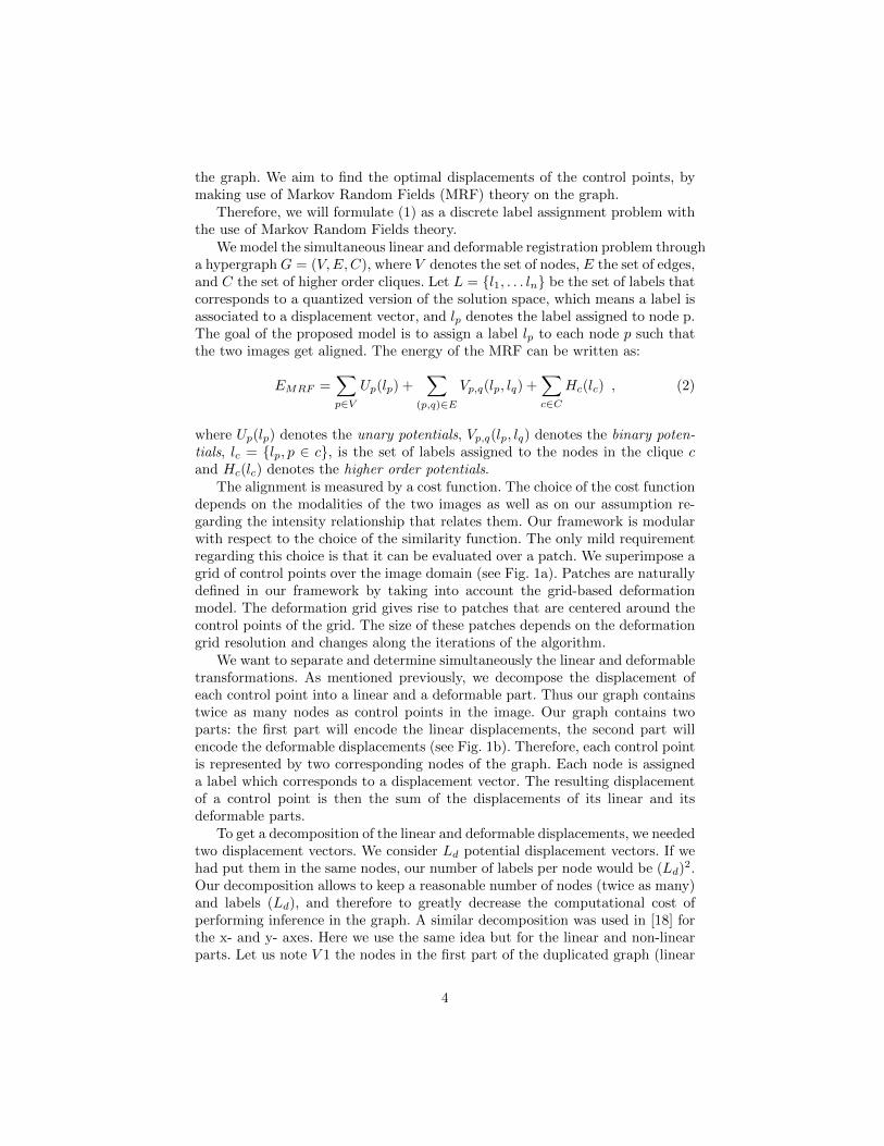
The alignment is measured by a cost function. The choice of the cost functiondepends on the modalities of the two images as well as on our assumption re-garding the intensity relationship that relates them. Our framework is modularwith respect to the choice of the similarity function. The only mild requirementregarding this choice is that it can be evaluated over a patch. We superimpose agrid of control points over the image domain (see Fig. 1a). Patches are naturallydefined in our framework by taking into account the grid-based deformationmodel. The deformation grid gives rise to patches that are centered around thecontrol points of the grid. The size of these patches depends on the deformationgrid resolution and changes along the iterations of the algorithm.
We want to separate and determine simultaneously the linear and deformabletransformations. As mentioned previously, we decompose the displacement ofeach control point into a linear and a deformable part. Thus our graph containstwice as many nodes as control points in the image. Our graph contains twoparts: the first part will encode the linear displacements, the second part willencode the deformable displacements (see Fig. 1b). Therefore, each control pointis represented by two corresponding nodes of the graph. Each node is assigneda label which corresponds to a displacement vector. The resulting displacementof a control point is then the sum of the displacements of its linear and itsdeformable parts.
To get a decomposition of the linear and deformable displacements, we neededtwo displacement vectors. We consider Ld potential displacement vectors. If wehad put them in the same nodes, our number of labels per node would be (Ld)2.Our decomposition allows to keep a reasonable number of nodes (twice as many)and labels (Ld), and therefore to greatly decrease the computational cost ofperforming inference in the graph. A similar decomposition was used in [18] forthe x- and y- axes. Here we use the same idea but for the linear and non-linearparts. Let us note V 1 the nodes in the first part of the duplicated graph (linear
4
(a) (b)
Fig. 1: a) An example of the grid of control points that is superimposed ontothe image. The control points are the intersections of the red grid. b) The graphcontains two parts, each point of the grid of control points is duplicated into twonodes, one in each part. We show here a 2D example for ease of visualization.
part), and V 2 those in the second part (deformable part):
V = V 1 ∪ V 2. (3)
The displacement of each control point is the sum of the two displacementsvectors, or labels, associated to the two nodes, one in V 1 and one in V 2 as-sociated to the control point. The labels of all the nodes in V 1 give the affinetransformation, those in V 2 the deformable field and the sum corresponds to thewhole registration.
2.1 Graph Construction
Let us now define C, the set of cliques. In our framework, the cliques havevery different goals. Edges connecting nodes in V 2 ensure the smoothness ofthe deformable displacements. So there is an edge between between each pair ofneighbouring nodes, which form a grid that is similar to the one in [16], thatwas used to compute deformable deformations. The cliques in V 1 are higherorder edges, and they ensure that the linear displacements of all the points forma coherent linear transformation of the image. Finally, the data term shouldcapture the interactions between pairs of linear and deformable displacementsso each pair of duplicated nodes (one in V 1, one in V 2) will be linked by anedge.
Unary Potentials. To ensure the algorithm prefers large linear displacementsinstead of large deformable ones, we employ a unary potential penalizing the
5
norm of the vector of the displacement vector for nodes in the deformable partV 2.
Up(lp) = ‖lp‖ ∀p ∈ V 2. (4)
This potential is defined for every node in V 2, where lp corresponds to a de-formable displacement. There are no unary potentials for the nodes in V 1.
Binary Potentials.
Smoothing Term. A regularization term operating between nodes in V 2 is nec-essary in order to ensure the deformable registration is smooth. This can beachieved by penalizing the vector differences between neighbouring nodes:
Vp,q(lp, lq) =‖(q + lq)− (p+ lp)‖
‖q − p‖∀(p, q) ∈ V 22, (5)
where p and q represent two neighbouring nodes, both in V 2.
Data Term. In order to quantify the alignment of the two images, we employ apatch-based similarity criterion, i.e. we compare a patch from the source imageBp,q with a patch in the target domain Blp+lq . This patch is centered at onecontrol point but its displacement is defined by two nodes, p ∈ V 1, q ∈ V 2. Theserepresent the concatenation of the affine and deformable part of the deformation.The data term is defined as:
Vp,q(lp, lq) = ρ(Bp,qBlp+lq ) ∀(p, q) ∈ V 1× V 2. (6)
There is no constraint imposed on the choice of the matching criterion ρ.The proposed model can encompass a wide choice of intensity-based similaritymeasures, from the sum of absolute difference (SAD) to statistical measures formultimodal registration like mutual information [21]. There are no pairwise edgesbetween nodes in V 1. Instead, nodes in V 1 are connected through hyperedges(see next paragraph).
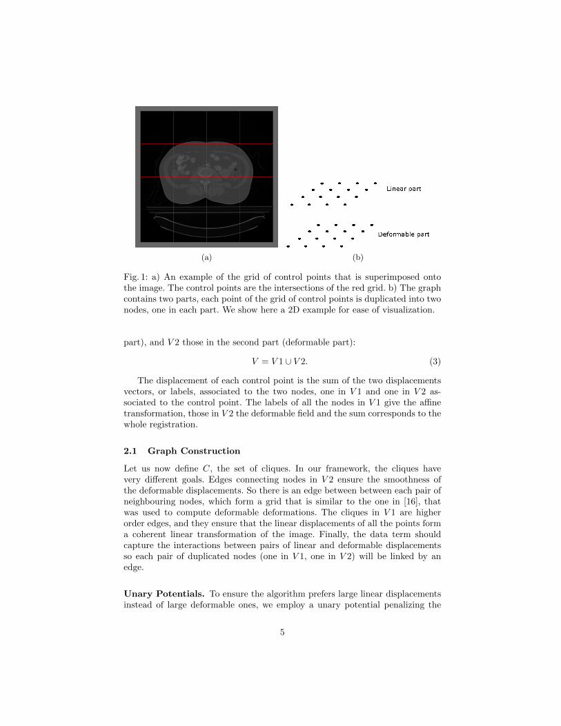
Higher Order Terms. The higher order potentials are defined as in [4]. Tripletsand a special clique called λ-clique ensure the linearity of the transformation. V 1is a grid of points with the shape of a cube in 3D (or a square in 2D). A tripletregroups any set of three neighbouring nodes in V1 which form a line parallel toone of the axes of the cube (x, y, z). A λ-clique is an hyperedge containing fournodes in the shape of a λ. There is one λ-clique on each face of the cube in 3D,so six in total (and only one in 2D). An example of those cliques for a 2D gridused for a 2D registration is shown in Fig. 2a. For a triplet c = p, q, r and theirrespective labels lp, lq, lr, the higher order potential is defined as:
Hc(lc) =
{0 if (lp + lr − 2lq = 0)
∞ otherwise .(7)
6
(a) (b)
Fig. 2: a) The complete graphical model for simultaneous linear and deformableregistration in 2D. (some triplets are omitted for clarity). Binary potentials arerepresented by black links connecting graph nodes; graph nodes that are relatedby triplets are grouped by ellipses, while the λ-clique is shown in green. b) Thedecomposition of the original problem in slave subproblems for the 2D case:there is one subproblem for every line in V 1 (vertical rectangles here), for everyλ-clique, and one (denoted by the bigger orange square) that encompasses everynode and binary edge of the graph.
The λ-clique contains four points p,q,r, and s. The points p, q, r satisfy the samecondition as the previously mentioned triplet. They are not part of the formerset because they are aligned along a diagonal, not an axis of the cube. If weare searching for a rigid transformation, or for a similarity, an additional con-straint is imposed in the λ-clique. It is detailed in [4]. If we are looking for anaffine transformation, we do not have to add anything else. These higher orderpotentials alone ensure the global transformation estimated by the linear partof the graph V 1 lies within the requested set of transformations (affine, rigid,similarity).
2.2 Optimization algorithm
To solve the MRF, we use DD-ADMM [1]. Dual Decomposition [12] consists indecomposing a global difficult problem into smaller solvable subproblems (re-ferred to as slaves) and then extracting a solution by cleverly combining thesolutions from these subproblems. The only requirement for the choice of thesubproblems is that they cover (at least once) every node, edge, and hyperedgeof the graph that models the problem. DD-ADMM improves Dual Decomposi-tion by accelerating its convergence. In our experiments, Dual Decompositionneeded too many iterations (more than 10000 iterations) and sometimes it neveragreed to a consensus while DD-ADMM reached a consensus generally between100 and 1000 iterations. Other optimisation algorithms performed badly in ourexperiments, mainly because of the hard constraint on the higher order terms.The time required for the optimisation was more than one day. In our case,the difficulty of the inference of the optimization displacements lies in the pres-ence of the higher order cliques. Here, the graph is decomposed into a grid andinto trees that constitute the set of subproblems. The slave problems can be
7
solved independently from one another, thus allowing for the parallelization ofthe computation.
In our case, in the affine part of the graph, a slave problem is defined for eachline parallel to a coordinate axis in the first part of the grid, and a slave for eachλ-clique. An example of the different slaves in 2D is illustrated in Fig. 2b. Oneof the slave contains all the nodes of the graph but only the edges correspondingto the smoothing term and the edges encoding the data term. In this slave, thenodes in V 1 only belong to one edge. Thus we can send a message from thisnode to the other end of the edge, like in Message-Passing algorithm, to put allneeded information into the unary of the node in V 2. Then we have a simpleslave and we optimize it using the Fast-PD algorithm [13].
3 Experimental Validation
3.1 Implementation Details
The algorithm uses an iterative coarse-to-fine refinement process. The resolu-tion of the image is reduced at the first steps to accelerate the computation. Thelabel space is successively refined to explore a large number of displacementswhile keeping a reasonable execution time. The label space corresponds to a dis-cretization of potential displacement vectors that are densely sampled followinga regular grid pattern around each node. The maximal length of the displace-ment vectors is 0.4 times the deformation grid spacing. The length is iterativelyreduced along the iterations. We used up to 7 iterations in our experiments. Thesuccessive label space refinement allows to keep the number of labels quite small,33 or 53, while reaching sub-millimeter registration accuracy. The grid contains33 control points at the first iterations and is increased to 93.
The algorithm is implemented in C++. The tests were performed on a 64bits machine with a Intel Xeon W3670 processor and 16 Go of RAM. The meanrunning time for 3D volumes was about 160 seconds when using SAD as thesimilarity criterion.
3.2 Synthetic Data
We use a database of abdomen 3D CT images, containing 6 images of the samepatient at different time points. Two organs have been manually segmented bymedical doctors, the sigmoid and the bladder. The image dimension is about512*512*121 with a physical spacing of 0.92*0.92*4 mm, with small variationson the images. We apply 22 simulated affine transformations on one image. Wethen applied a small deformation field (see Fig. 4a) to the transformed image.This deformation field is small in the sense it should not contain any global lin-ear transformation. We then try to register these deformed images (see Fig. 4b)to the original one. Simulated rotations lie between 0˚and 5˚and translationsreach 20mm. Mean initial error was about 10mm. We used the Sum of Abso-lute Differences (SAD). We want to compare the affine transformation we find
8
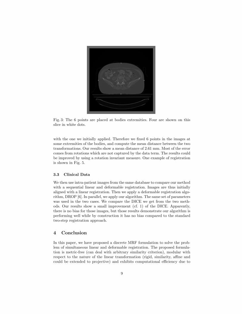
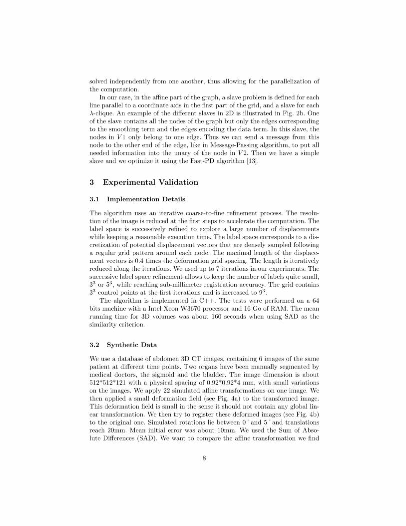
Fig. 3: The 6 points are placed at bodies extremities. Four are shown on thisslice in white dots.
with the one we initially applied. Therefore we fixed 6 points in the images atsome extremities of the bodies, and compute the mean distance between the twotransformations. Our results show a mean distance of 2.61 mm. Most of the errorcomes from rotations which are not captured by the data term. The results couldbe improved by using a rotation invariant measure. One example of registrationis shown in Fig. 5.
3.3 Clinical Data
We then use intra-patient images from the same database to compare our methodwith a sequential linear and deformable registration. Images are thus initiallyaligned with a linear registration. Then we apply a deformable registration algo-rithm, DROP [6]. In parallel, we apply our algorithm. The same set of parameterswas used in the two cases. We compare the DICE we get from the two meth-ods. Our results show a small improvement (cf. 1) of the DICE. Apparently,there is no bias for those images, but those results demonstrate our algorithm isperforming well while by construction it has no bias compared to the standardtwo-step registration approach.
4 Conclusion
In this paper, we have proposed a discrete MRF formulation to solve the prob-lem of simultaneous linear and deformable registration. The proposed formula-tion is metric-free (can deal with arbitrary similarity criterion), modular withrespect to the nature of the linear transformation (rigid, similarity, affine andcould be extended to projective) and exhibits computational efficiency due to
9
(a) (b)
Fig. 4: a) A slice of the deformation field applied to the image. b) One exampleof an image transformed by the composition of simulated affine and deformabledeformations.
DICE Bladder Sigmoid
Before registration 45.61 39.383Consecutive registration 78.15 68.55
Our registration 78.47 68.64
Table 1: DICE overlap ratio obtained for two organs. Results before and afterregistration using the proposed framework and a standard two-step registrationpipeline are shown.
its relative local nature and the designed search space. The performance of themethod on 3D multi-modal medical data demonstrate its potential for applica-tions. Contrary to the commonly used sequential linear/deformable registration,our scheme is based on a mathematical framework without any decoupling as-sumption which prevents from a potential bias. Despite the fact that it does notshow significant improvement in our experiments, it performs as well as usualmethods and would be able to tackle a potential bias where it appears. Moreoverthis approach is fast compared to state of the art methods.
Furthermore, mapping from 2D to 3D is a great problem of important interesteither in vision or in medical imaging towards image-based navigation/guidance.The same concept that was proposed here to decompose 2D-2D or 3D-3D defor-mations in linear and non-linear components can be also applied to 2D-3D. Theclinical impact of such a component in computer assisted surgery is currentlyunder investigation.
10
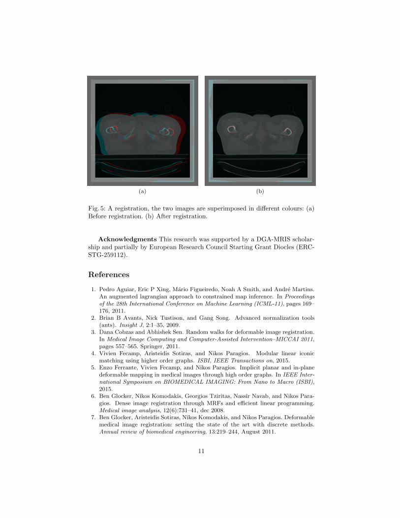
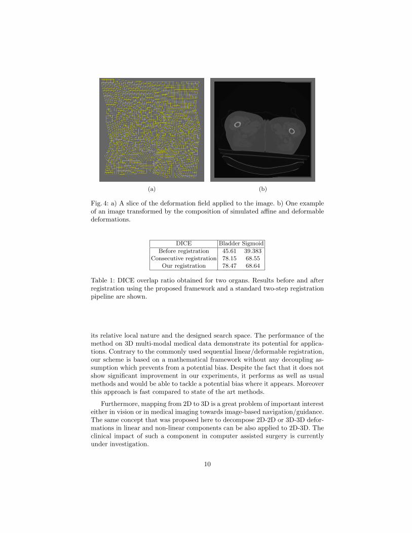
(a) (b)
Fig. 5: A registration, the two images are superimposed in different colours: (a)Before registration. (b) After registration.
Acknowledgments This research was supported by a DGA-MRIS scholar-ship and partially by European Research Council Starting Grant Diocles (ERC-STG-259112).
References
1. Pedro Aguiar, Eric P Xing, Mario Figueiredo, Noah A Smith, and Andre Martins.An augmented lagrangian approach to constrained map inference. In Proceedingsof the 28th International Conference on Machine Learning (ICML-11), pages 169–176, 2011.
2. Brian B Avants, Nick Tustison, and Gang Song. Advanced normalization tools(ants). Insight J, 2:1–35, 2009.
3. Dana Cobzas and Abhishek Sen. Random walks for deformable image registration.In Medical Image Computing and Computer-Assisted Intervention–MICCAI 2011,pages 557–565. Springer, 2011.
4. Vivien Fecamp, Aristeidis Sotiras, and Nikos Paragios. Modular linear iconicmatching using higher order graphs. ISBI, IEEE Transactions on, 2015.
5. Enzo Ferrante, Vivien Fecamp, and Nikos Paragios. Implicit planar and in-planedeformable mapping in medical images through high order graphs. In IEEE Inter-national Symposium on BIOMEDICAL IMAGING: From Nano to Macro (ISBI),2015.
6. Ben Glocker, Nikos Komodakis, Georgios Tziritas, Nassir Navab, and Nikos Para-gios. Dense image registration through MRFs and efficient linear programming.Medical image analysis, 12(6):731–41, dec 2008.
7. Ben Glocker, Aristeidis Sotiras, Nikos Komodakis, and Nikos Paragios. Deformablemedical image registration: setting the state of the art with discrete methods.Annual review of biomedical engineering, 13:219–244, August 2011.
11
8. Eldad Haber and Jan Modersitzki. Cofir: Coarse and fine image registration. SIAMReal-Time PDE-Constrained Optimization, pages 37–49, 2007.
9. Mark Jenkinson, Peter Bannister, Michael Brady, and Stephen Smith. ImprovedOptimization for the Robust and Accurate Linear Registration and Motion Cor-rection of Brain Images. NeuroImage, 17(2):825–841, oct 2002.
10. S. Klein, M. Staring, K. Murphy, M.A. Viergever, and J. Pluim. elastix: A toolboxfor intensity-based medical image registration. Medical Imaging, IEEE Transac-tions on, 29(1):196 –205, jan. 2010.
11. E. Kokiopoulou and P. Frossard. Minimum distance between pattern transfor-mation manifolds: Algorithm and applications. Pattern Analysis and MachineIntelligence, IEEE Transactions on, 31(7):1225 –1238, july 2009.
12. Nikos Komodakis, Nikos Paragios, and Georgios Tziritas. MRF energy minimiza-tion and beyond via dual decomposition. PAMI, 33(3):531–52, March 2011.
13. Nikos Komodakis, Georgios Tziritas, and Nikos Paragios. Fast, ApproximatelyOptimal Solutions for Single and Dynamic MRFs. IEEE Conference on ComputerVision and Pattern Recognition, D(2):1–8, 2007.
14. Dongjin Kwon, Kyong Joon Lee, Il Dong Yun, and Sang Uk Lee. Nonrigid imageregistration using dynamic higher-order mrf model. In Computer Vision ECCV2008, volume 5302 of Lecture Notes in Computer Science, pages 373–386. SpringerBerlin Heidelberg, 2008.
15. Yangming Ou, Aristeidis Sotiras, Nikos Paragios, and Christos Davatzikos.Dramms: Deformable registration via attribute matching and mutual-saliencyweighting. Medical image analysis, 15(4):622–639, 2011.
16. D Rueckert, L I Sonoda, C Hayes, D L Hill, M O Leach, and D J Hawkes. Nonrigidregistration using free-form deformations: application to breast MR images. IEEEtransactions on medical imaging, 18(8):712–21, August 1999.
17. R. Shekhar and V. Zagrodsky. Mutual information-based rigid and nonrigid reg-istration of ultrasound volumes. Medical Imaging, IEEE Transactions on, 21(1):9–22, jan. 2002.
18. Alexander Shekhovtsov and Ivan Kovtun. Efficient MRF Deformation Model forNon-Rigid Image Matching. CVPR, pages 0–5, 2007.
19. Aristeidis Sotiras, Christos Davatzikos, and Nikos Paragios. Deformable medicalimage registration: A survey. Medical Imaging, IEEE Transactions on, 32(7):1153–1190, 2013.
20. Tom Vercauteren, Xavier Pennec, Aymeric Perchant, and Nicholas Ayache. Diffeo-morphic demons: Efficient non-parametric image registration. NeuroImage, 45(1,Supplement 1):S61 – S72, 2009.
21. Paul Viola and William M. Wells. Alignment by maximization of mutual informa-tion. International Journal of Computer Vision, 24(2):137–154, 1997.
22. Darko Zikic, Ben Glocker, Oliver Kutter, Martin Groher, Nikos Komodakis, AliKamen, Nikos Paragios, and Nassir Navab. Linear intensity-based image registra-tion by Markov random fields and discrete optimization. Medical Image Analysis,14(4):550–562, 2010.
12