Embed Size (px)
Citation preview

ALITY
AMET ACADEMY OF MARITIME EDUCATION AND TRAINING
DEEMED TO BE UNIVERSITY (Under Section 3 of UGC Act 1956)
Title of the Project: Modellio and simulorhon.
ynagtieg Bicycte orm Permanent
projer Home Internship Report LiCynognt Se oot
Submitted by: P. Authy leim AaRs o A)
V. Signature of Mentor

AMET oUALIT
ACADEMY OF MARITIME EDUCATION AND TRAINING DEEMED TO BE UNIVERSITY (Under Sectlon 3 of UGC Act 1956)
ANAL
BONAFIDE CERTIFICATE
This is to certify that the home based internship entitled
".. e A0d..imairhon..AzmnatiA...BA.. . n..peK.cKarenk..magnat.9je bmam4.ve.cenc .
...submitted
by....P0sT l0rw... ...!V..
Reg.No:....FARA.Lepo..... ..... semester during year eeeo***sso*o********
for the degree of . a... gin . bonafide record of technical work carried out by him under my
of is a
supervision.
Signature. Mentor Signature of Dean/HoD

QUALIT
AMET ACADEMY OF MARITIME EDUCATION AND TRAINING
DEEMED TO BE UNIVERSITY (Under Section 3 of UGC Act 1956)
INTERNSHIP ALLOCATION REPORT 2019-20 Name of the Department: Electrical and Electronics Engineering (in the view of advisory from the AICTE, Intermships for the year 2019-20 are offered by the Department of itself to facilitate the students to take up required work from their home itself during the lockdown period due to COVID19 outbreak)
Name of the Programme :Electrical and Electronics Engineering
Year of study and Batch/group:
Name of the Mentor Vleayn eeyan Title of the assigned internship:
Nature of Intemship : Individual/ Group
Reg no of the students who are assigned with this internship:
Total No of hours Required to complete the intermship: IS dayy
Signature of Mentor Signature of Internal Examinerignature of HoD/Dean

LITY
AMET ACADEMY OF MARITIME EDUCATION AND TRAINING
DEEMED TO BE UNIVERSITY (Under Section 3 of UGC Act 1956)
INTERNSHIP ALLOCATION REPORT 2019-20
Name the Department: Electrical and Electronics Engineering in the view of advisory from the AICTE, Internships for the year 2019-20 are offered by the
Department of itself to facilitate the students to take up required work from their home itself
during the lockdown period due to COVID19 outbreak)
Name of the student Register No. and Roll No
Programme of study Year and Batch/Group
Semester Title of Internship/po-Mo detiq epd muloim 3 Gma hs Dig
Duration of Internship Mentor of the student
Evaluation of the Department:
P.MusulewnA Arps L8po
upe - IV Dem
Pns
S.no Criteria Max Marks Marks allotted 10 Regularity in the maintenance of
daily Adequacy and quality of Information
recorded Drawings, sketches, and data
recorded Thought process and data recording
techniques used Organization of information Originality of information report Adequacy and purposeful write-up
of the internship report Organization, format, drawing, sketched, style, language etc of
internship Report Practical application, re lationshipwith basic theory and concepts
10 Presentation skills
10
10
20
10
10
10 t P 10
Total 100
Signature of InternalExaminer
Signature of HoD/Dean Signature of Mentor
1
Modelling and Simulation of Gymnastics Bicycle with Permanent
Magnet Synchronous Generator
A THESIS
Submitted by
P MUTHUKUMAR (AMPS18007)
In partial fulfillment for the award of the degree of
MASTER OF ENGINEERING IN
POWER SYSTEMS
AMET DEEMED TO BE UNIVERSITY ::CHENNAI 603112
JUN 2020

2
ACKNOWLEDGEMENT
We wish to express our sincere and humble thanks to our chancellor
Dr. J. RAMACHANDRAN for providing the necessary facilities in the college
premises to carry out the project
We would like to express our sincere thanks towards our beloved Vice –
Chancellor, Col.Dr.G.THIRUVASAGAM for providing us with an
environment to complete the project successfully.
We wish to express our heartiest thanks to Dr.T. SASILATHA, Dean and
Professor, Department of EEE for her advice and motivation, which helped us to
accomplish this project work.
We are grateful to our guide, Dr.V. Karthikeyan, M.E, Ph.D., Professor,
and Department of EEE for his valuable and precious guidance to our project.
We would like to thank our parents and friends for moral financial support.
Finally, we thank Almighty for making us capable and giving us the dedication
and determination to complete the project on time.
P MUTHUKUMAR
3
Abstract
This paper presents the modelling and simulation of Manual Pedalling with
permanent magnet synchronous generator. In this paper, the modelling and
simulations of a variable-speed Manual Pedalling along with permanent magnet
synchronous generator is presented. Now a day, the energy production by wind
generators and solar energy generation has recently been increasing, because its
creation is green; therefore, this proposal also based on the green creation by the
Re-Creating the Human Movement in the routine lifecycle and the technology
designed for the establishment of energy through Manual Pedalling brings great
challenges in the exploration. A mathematical model of Manual Pedalling is
necessary to understand the behavior of the Manual Pedalling over its area of
operation since it allows for the evolution of inclusive control algorithms that aid
in ideal operation of a Manual Pedalling system. Modelling gives us an overview
of the proposed system and also allow control of Manual Pedalling system’s
performance. Outcome results show that the speed regulation was very good. In
long lasting system, the imbalance of rotor speed was almost inconsiderable in
spite of the uninterrupted imbalance of the Pedalling speed within the interval of
120 to 1000ms.
Keywords— Manual Pedalling, rotor speed, PMSG.
TABLE OF CONTENTS

4
Chapter
No
TITLE Page
No
ACKNOWLEDGEMENT 3
ABSTRACT 4
TABLE OF CONTENTS 5
LIST OF FIGURES 6
1 INTRODUCTION 7
2 CONSTRUCTION
2.1 Construction of PMSG 8
2.1.1 Hall sensors 9
2.2 Working Principle & Operations of PMSG 10
3 PMSG Drive 11
4 SYSTEM CONFIGURATION
4.1. Block Diagram 12
4.2. Description 12
4.3. Mathematical Modeling of PMSG 13
5 Alternative Flux Linkage Parameterization
5.1. Three-Phase Sinusoidal Modeling 21
5.2. Three-Phase Trapezoidal Modeling 22
5.3. Mechanical Systems 23
6 Mathematical Modelling
6.1 Modelling of Pedaling Gymnastics Bicycle 25
6.2 Modelling of PMSG 26
6.2.1 Flow Equation 27
6.2.2 Voltage Equation 27
7 Control Strategy 28
8 MATLAB Simulation
8.1 Simulation 29
9 Characteristic Simulation Output Waveform 30
10 Conclusion 31
11 Reference Papers 32

5
LIST OF FIGURES
Figure
No
TITLE
Page
No
1 Cross Sectional View of PMSG 8
2 Rotor Core 9
3 Proposed System Block Diagram 12
4 Phase –Phase Inductance 21
5 Trapezoidal Waveform 22
6 Mechanical Block Diagram 24
7 Torque Developed by Pedal 26
8 Control Strategy 28
9 MATLAB Simulation 29
10 Simulation Output Waveform 30
CHAPTER-1
6
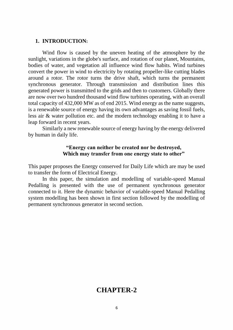
1. INTRODUCTION:
Wind flow is caused by the uneven heating of the atmosphere by the
sunlight, variations in the globe's surface, and rotation of our planet, Mountains,
bodies of water, and vegetation all influence wind flow habits. Wind turbines
convert the power in wind to electricity by rotating propeller-like cutting blades
around a rotor. The rotor turns the drive shaft, which turns the permanent
synchronous generator. Through transmission and distribution lines this
generated power is transmitted to the grids and then to customers. Globally there
are now over two hundred thousand wind flow turbines operating, with an overall
total capacity of 432,000 MW as of end 2015. Wind energy as the name suggests,
is a renewable source of energy having its own advantages as saving fossil fuels,
less air & water pollution etc. and the modern technology enabling it to have a
leap forward in recent years.
Similarly a new renewable source of energy having by the energy delivered
by human in daily life.
“Energy can neither be created nor be destroyed,
Which may transfer from one energy state to other”
This paper proposes the Energy conserved for Daily Life which are may be used
to transfer the form of Electrical Energy.
In this paper, the simulation and modelling of variable-speed Manual
Pedalling is presented with the use of permanent synchronous generator
connected to it. Here the dynamic behavior of variable-speed Manual Pedalling
system modelling has been shown in first section followed by the modelling of
permanent synchronous generator in second section.
CHAPTER-2
7
2. Construction & Working of PMSG:
2.1. Construction of PMSG:
The basic construction of PMSG is same as that of synchronous motor. The
only difference lies with the rotor. Unlike synchronous motor, there is no filed
winding on the rotor of PMSG. Field poles are created by using permanent
magnet. These Permanent magnets are made up of high permeability and high
coercivity materials like Samarium-Cobalt and Neodium-Iron-Boron. Neodium-
Iron-Boron is mostly used due to its ease of availability and cost effectiveness.
Theses permanent magnets are mounted on the rotor core.Based on the mounting
arrangement of magnet on rotor core, Permanent Magnet Synchronous Motor
(PMSG) can be categorized into two types: Surface Mounted PMSGs and Buried
or interior PMSGs
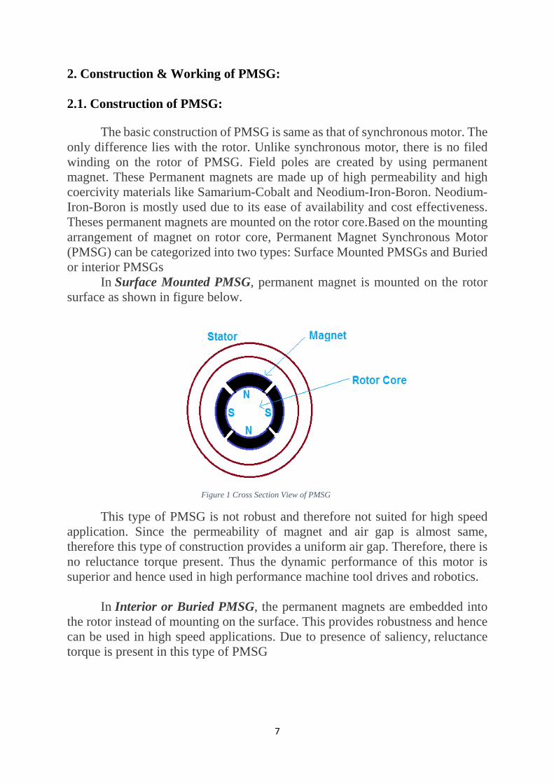
In Surface Mounted PMSG, permanent magnet is mounted on the rotor
surface as shown in figure below.
Figure 1 Cross Section View of PMSG
This type of PMSG is not robust and therefore not suited for high speed
application. Since the permeability of magnet and air gap is almost same,
therefore this type of construction provides a uniform air gap. Therefore, there is
no reluctance torque present. Thus the dynamic performance of this motor is
superior and hence used in high performance machine tool drives and robotics.
In Interior or Buried PMSG, the permanent magnets are embedded into
the rotor instead of mounting on the surface. This provides robustness and hence
can be used in high speed applications. Due to presence of saliency, reluctance
torque is present in this type of PMSG
8
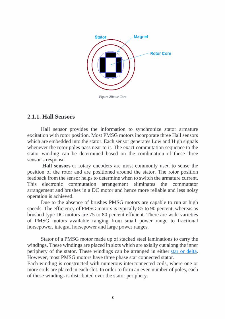
Figure 2Rotor Core
2.1.1. Hall Sensors
Hall sensor provides the information to synchronize stator armature
excitation with rotor position. Most PMSG motors incorporate three Hall sensors
which are embedded into the stator. Each sensor generates Low and High signals
whenever the rotor poles pass near to it. The exact commutation sequence to the
stator winding can be determined based on the combination of these three
sensor’s response.
Hall sensors or rotary encoders are most commonly used to sense the
position of the rotor and are positioned around the stator. The rotor position
feedback from the sensor helps to determine when to switch the armature current.
This electronic commutation arrangement eliminates the commutator
arrangement and brushes in a DC motor and hence more reliable and less noisy
operation is achieved.
Due to the absence of brushes PMSG motors are capable to run at high
speeds. The efficiency of PMSG motors is typically 85 to 90 percent, whereas as
brushed type DC motors are 75 to 80 percent efficient. There are wide varieties
of PMSG motors available ranging from small power range to fractional
horsepower, integral horsepower and large power ranges.
Stator of a PMSG motor made up of stacked steel laminations to carry the
windings. These windings are placed in slots which are axially cut along the inner
periphery of the stator. These windings can be arranged in either star or delta.
However, most PMSG motors have three phase star connected stator.
Each winding is constructed with numerous interconnected coils, where one or
more coils are placed in each slot. In order to form an even number of poles, each
of these windings is distributed over the stator periphery.

9
The stator must be chosen with the correct rating of the voltage depending
on the power supply capability. For robotics, automotive and small actuating
applications, 48 V or less voltage PMSG motors are preferred. For industrial
applications and automation systems, 100 V or higher rating motors are used.
2.2 Working Principle of PMSG:
The working principle of permanent magnet synchronous motor is same as
that of synchronous motor. When three phase winding of stator is energized from
3 phase supply, rotating magnetic field is set up in the air gap. At synchronous
speed, the rotor field poles locks with the rotating magnetic field to produce
torque and hence rotor continues to rotate.
As we know that synchronous motors are not self-starting, PMSG needs to
be started somehow. Since there is no winding on the rotor, induction windings
for starting is not applicable for such motors and therefore variable frequency
power supply for this purpose.
PMSM motor works on the principle similar to that of a conventional DC
motor, i.e., the Lorentz force law which states that whenever a current carrying
conductor placed in a magnetic field it experiences a force. As a consequence of
reaction force, the magnet will experience an equal and opposite force. In case
PMSM motor, the current carrying conductor is stationary while the permanent
magnet moves
When the stator coils are electrically switched by a supply source, it
becomes electromagnet and starts producing the uniform field in the air gap.
Though the source of supply is DC, switching makes to generate an AC voltage
waveform with trapezoidal shape. Due to the force of interaction between
electromagnet stator and permanent magnet rotor, the rotor continues to rotate.
Consider the figure below in which motor stator is excited based on
different switching states. With the switching of windings as High and Low
signals, corresponding winding energized as North and South poles. The
permanent magnet rotor with North and South poles align with stator poles
causing motor to rotate.
Observe that motor produces torque because of the development of
attraction forces (when North-South or South-North alignment) and repulsion
forces (when North-North or South-South alignment). By this way motor moves
in a clockwise direction. As it act as Generator Reverse the process vice versa.

10
CHAPTER-3
3. PMSG Drive:
As described above that the electronic controller circuit energizes
appropriate motor winding by turning transistor or other solid state switches to
rotate the motor continuously.
The figure below shows the simple PMSG motor drive circuit which
consists of MOSFET Bridge (also called as Inverter Bridge), electronic
controller, Hall Effect sensor and PMSG motor. Here, Hall-effect sensors are
used for position and speed feedback.
The electronic controller can be a microcontroller unit or microprocessor
or DSP processor or FPGA unit or any other controller. This controller receives
these signals, processes them and sends the control signals to the MOSFET driver
circuit.
In addition to the switching for a rated speed of the motor, additional
electronic circuitry changes the motor speed based on required application.
These speed control units are generally implemented with PID
controllers to have precise control. It is also possible to produce four-quadrant
operation from the motor whilst maintaining good efficiency throughout the
speed variations using modern drives.

11
CHAPTER-4
4. SYSTEM CONFIGURATION
In the present scenario, the world is shifting toward the renewable energy
sources as like wind energy, solar energy, etc. To suppress electricity shortage
and to control the fast end of fossil fuels. Being a part of this a variable-speed
Manual Pedalling generation system modelling is presented with its simulation
by using PMSG [4]. The purpose of this paper is to analyze the dynamics of the
variable-speed Manual Pedalling. In the following section, an overview of the
model is presented by utilizing the mathematical modelling equations of variable-
speed Manual Pedalling system and PMSG respectively.
Fig.1 shows the block diagram of the system as variable-speed Manual
Pedalling connected to gear drive train block followed by PMSG and load.
MATLAB/simulation is used for modelling and analysis.
Figure 3 Proposed system Block Diagram
12
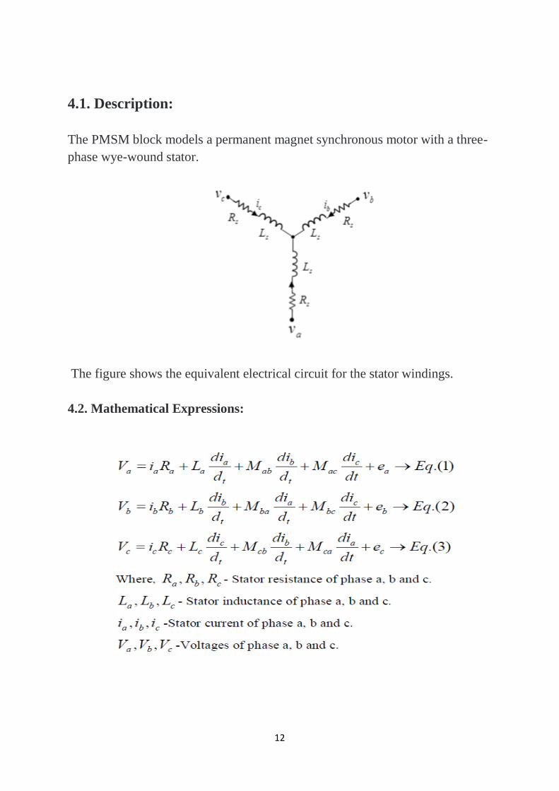
4.1. Description:
The PMSM block models a permanent magnet synchronous motor with a three-
phase wye-wound stator.
The figure shows the equivalent electrical circuit for the stator windings.
4.2. Mathematical Expressions:
13
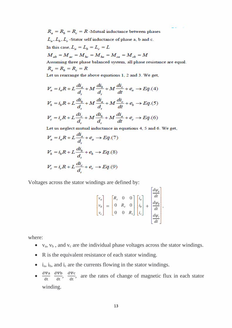
Voltages across the stator windings are defined by:
where:
va, vb , and vc are the individual phase voltages across the stator windings.
R is the equivalent resistance of each stator winding.
ia, ib, and ic are the currents flowing in the stator windings.
ⅆΨa
ⅆt ⅆΨb
ⅆt,
ⅆΨc
ⅆt, are the rates of change of magnetic flux in each stator
winding.

14
The permanent magnet and the three windings contribute to the total flux
linking each winding.
The total flux is defined by:
where:
ψ a, ψ b, and ψc care the total fluxes linking each stator winding.
La , Lb , and Lc are the self-inductances of the stator windings.
L aa, Lbb , Lcc , and so on, are the mutual inductances of the stator windings.
ψ , ψ , and ψ are the permanent magnet fluxes linking the stator windings.
The inductances in the stator windings are functions of rotor electrical angle,
defined by:

15
16

17
where
L = L + M + 3/2 L . L is the stator d-axis inductance.
L = L + M − 3/2 L . L is the stator q-axis inductance.
L = L – 2M . L is the stator zero-sequence inductance.
ω is the rotor mechanical rotational speed.
N is the number of rotor permanent magnet pole pairs.
T is the rotor torque. Torque flows from the motor case (block physical port C)
to the motor rotor (block physical port R).
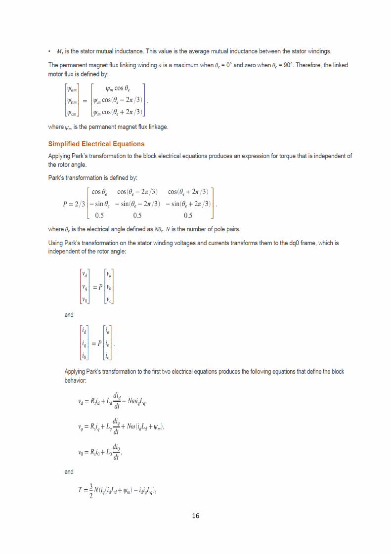
The PMSM block uses the original, non-orthogonal implementation of the Park
transform. If you try to apply the alternative implementation, you get different
results for the dq0 voltage and currents.

18
Chapter-5
5. Alternative Flux Linkage Parameterization
You can parameterize the motor using the back EMF or torque constants
which are more commonly given on motor datasheets by using the Permanent
magnet flux linkage option.
The back EMF constant is defined as the peak voltage induced by the
permanent magnet in each of the phases per unit rotational speed.
It is related to peak permanent magnet flux linkage by:
ke = Nψm.
From this definition, it follows that the back EMF eph for one phase is
given by:
eph = keω.
The torque constant is defined as the peak torque induced by each of the
phases per unit current.
It is numerically identical in value to the back EMF constant when both
are expressed in SI units:
kt = Nψm
When Ld=Lq, and when the currents in all three phases are balanced, it
follows that the combined torque T is given by:

19
5.1. Three-Phase Sinusoidal Model Electrical System

20
Figure 4Phase-Phase Inductance
21
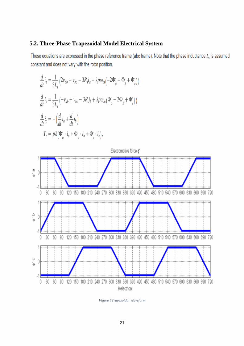
5.2. Three-Phase Trapezoidal Model Electrical System
Figure 5Trapezoidal Waveform

22
5.3. Mechanical System (for all models):

23
Figure 6Mechanical Block Diagram
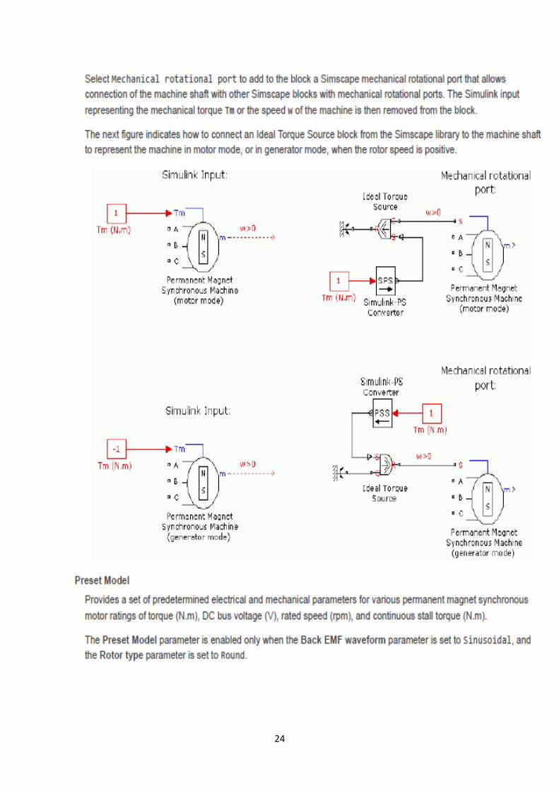
24

25
CHAPTER-6
6. MATHEMATICAL MODELLING:
6.1. Modelling of Pedalling Gymnastics Bicycle:
Mechanical torque developed by Pedal,
Figure 7Torque developed by pedal
The length of a bicycle pedal arm is r =0.152m, and a downward force of
F = 111N is applied by the foot.
= r F sin Where, r = length of bicycle pedal arm
F = Applied Force
= angle between arm and vertical line
i) When = 90 degree, sin = 1 at the time only the Force
completely appeared to Pedal.
ii) But, When = 180 degree, sin = 0 so the force exerts no torque
on the pedal. This is the situation when the pedal is at the bottom;
no amount of pushing down at this point can produce any torque on
the pedal.
6.2 Modelling of PMSG:
The permanent magnet synchronous machine (PMSG) is interesting for a
generator coupled to any system; despite the high cost which is its major
drawback, PMSG presents many advantages compared to other types of electric
machines(performance, robustness ... etc.).The PMSG transforms the mechanical
energy applied to the shaft by the pedal-based emulator to electrical power; it is
sent to the network via the DC bus or battery storage.
A model in the d-q reference (using Park transformation) of this machine
will be used. The d-q reference is a two-phase marker, equivalent phase marker,
easier to handle because electrical quantities evolve as continuous variables.
26
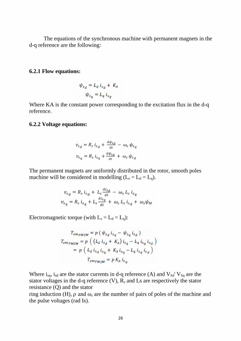
The equations of the synchronous machine with permanent magnets in the
d-q reference are the following:
6.2.1 Flow equations:
Where KA is the constant power corresponding to the excitation flux in the d-q
reference.
6.2.2 Voltage equations:
The permanent magnets are uniformly distributed in the rotor, smooth poles
machine will be considered in modelling (Ls = Ld = Lq).
Electromagnetic torque (with Ls = Ld = Lq):
Where isq, isd are the stator currents in d-q reference (A) and VSd' VSq are the
stator voltages in the d-q reference (V), Rs and Ls are respectively the stator
resistance (Q) and the stator
ring induction (H), and ωs are the number of pairs of poles of the machine and
the pulse voltages (rad Is).
27
CHAPTER-7
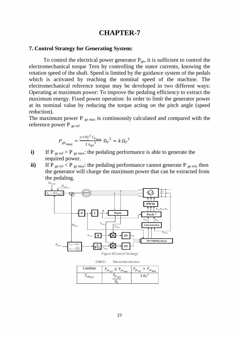
7. Control Strategy for Generating System:
To control the electrical power generator Pge, it is sufficient to control the
electromechanical torque Tern by controlling the stator currents, knowing the
rotation speed of the shaft. Speed is limited by the guidance system of the pedals
which is activated by reaching the nominal speed of the machine. The
electromechanical reference torque may be developed in two different ways:
Operating at maximum power: To improve the pedaling efficiency to extract the
maximum energy. Fixed power operation: In order to limit the generator power
at its nominal value by reducing the torque acting on the pitch angle (speed
reduction).
The maximum power P ge max is continuously calculated and compared with the
reference power P ge ref
i) If P ge ref > P ge max: the pedaling performance is able to generate the
required power.
ii) If P ge ref < P ge max: the pedaling performance cannot generate P ge ref, then
the generator will charge the maximum power that can be extracted from
the pedaling.
Figure 8Control Strategy

28
CHAPTER-8
8. MATLAB Simulations: A Simulink model of a Bicycle Pedaling with permanent magnet
synchronous generator (PMSG) built up using MATLAB /SIMULINK software. In this model,
Bicycle Pedaling shaft is mechanically connected with permanent magnet synchronous (drive
Train PMSG) which is connected to grid through three phase series RLC branch .Waveform of
voltage and current is sinusoidal and the simulation waveform for output mechanical power
and torque (Te & Tm) is also shown which are showing normal behavior after attaining a good
value for system.
a) Main Simulation:
Figure 9MATLAB Simulation
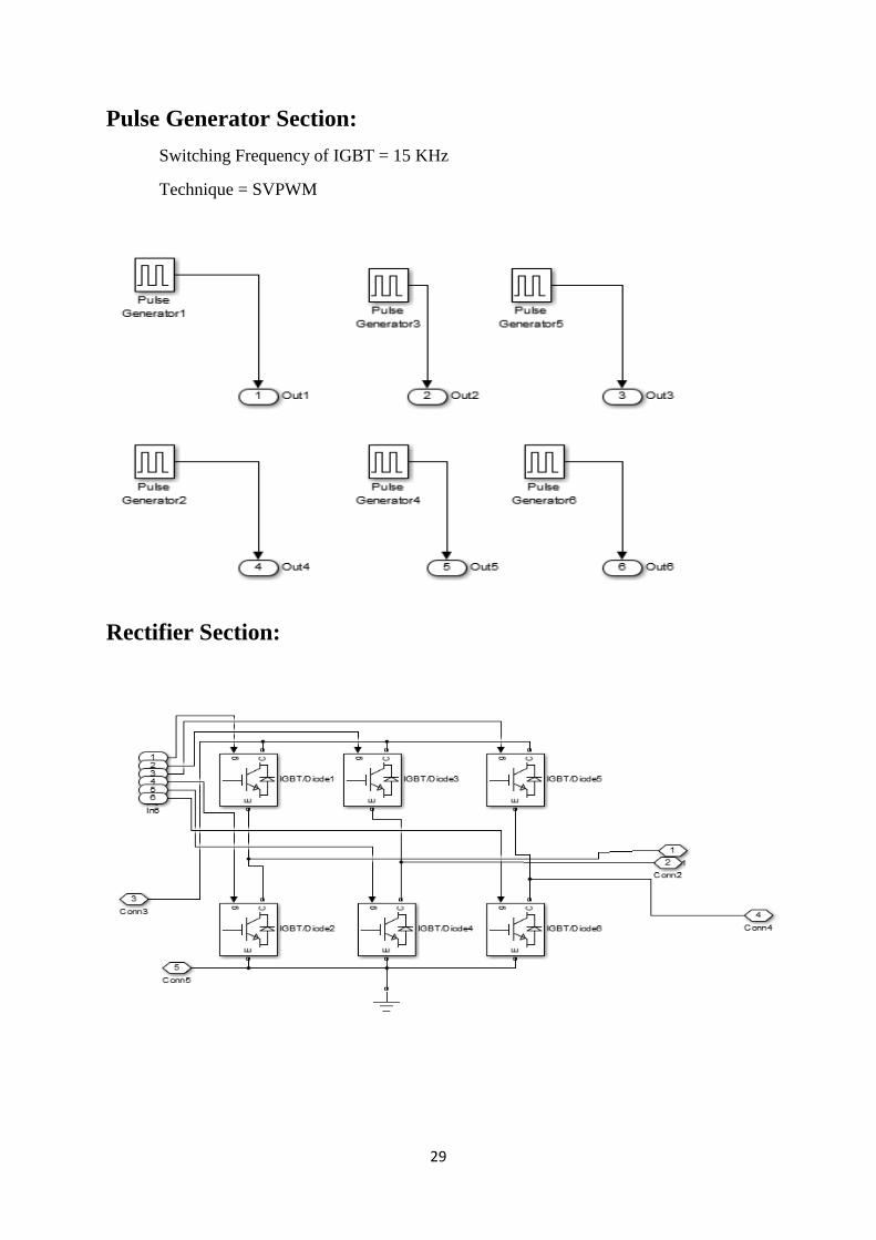
29
Pulse Generator Section:
Switching Frequency of IGBT = 15 KHz
Technique = SVPWM
Rectifier Section:

30
PMSG Specification:
In MATLAB Model
Number of Poles: 3
Back EMF waveform: Sinusoidal
Rotor Type: Round
Mechanical Input: Torque, Tm
Present Model:
Tm = 1.0 Nm;
Vdc=250 Volt;
Speed =1000 RPM;
Stator Phase resistance Rs (Ohm) =18.7 Ohm
Armature inductance (H) = 0.02682 H
Machine constant:
Specify: Flux linkage established by magnets (V.s)
Flux linkage: 0.1717
If Apply Torque = 0.5 Nm ,Will Get Speed = 500 RPM with 250 Vdc.
31
CHAPTER-9
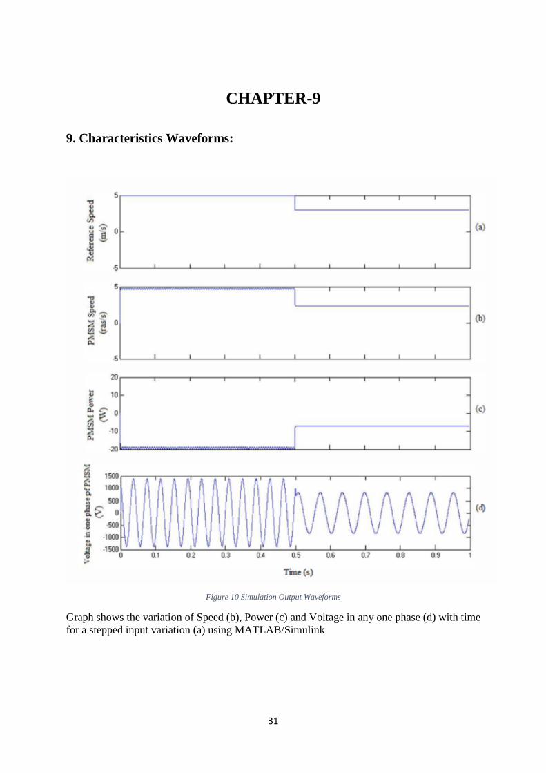
9. Characteristics Waveforms:
Figure 10 Simulation Output Waveforms
Graph shows the variation of Speed (b), Power (c) and Voltage in any one phase (d) with time
for a stepped input variation (a) using MATLAB/Simulink

32
CHAPTER-10
10. Conclusion:
The modelling of a variable speed Bicycle Pedaling with a permanent
magnet synchronous generator has been treated. The model has been
implemented in MATLAB/Simulink in order to validate the theoretical study.
The generator has been modelled in the d-q synchronous rotating reference frame,
taking into account different simplifications. There is therefore a real interest to
be able to generalize the use of the bond graph tool in electrical networks. So, in
future work, we will model the global production chain by using the bond graph
energetic approach, make the simulations in MATLAB software and draw a
comparison between the different methods.
33
REFERENCE
1. Samanvoraktj, Kumkratug, "Modelling and Simulation PMSG based on Wind Energy
Conversion System in MATLAB/SIMULlNK", The Second IntI. Conf. on Advances in
Electronics and Electrical Engineering -AEEE 2013.
2. Abdulhamed Hwas, Reza Katebi, "Wind Turbine Control Using PI Pitch Angle Controller",
IFAC Conference on Advances in PID Control PID'12 Brescia (Italy), March 28-30, 2012.
3. Vijayalakshmi, "Modelling and control of a Wind Turbine using Permanent Magnet
Synchronous Generator", International Journal of Engineering Science and Technology
(IJEST), Vol. 3 NO. 3 March 2011.
4. [1] J. S. Thongam, M. Tarbouchi, e tal.: An Optimium Speed MPPT Controller for Variable
Speed PMSG
5. Wind Energy Conversion Systems, 38th Annual Conference on IEEE Industrial Electronic
Society
6. (IECON), pp 4293-4297, (25-28 Oct. 2012).
7. Lakhdar Belhadji, Seddik Bacha, e tal.: Modeling and control of variable speed Micro-
Hydropower plant based on Axial-flow Turbine and Permanent Magnet Synchronous Generator
(MHPP-PMSG),37th International Conference on IEEE Industrial Electronic Society
(IECON), 2011, pp 896-901, (7-10
Nov; 2011).
8. Youssef. Errami, Mohamed Maaroufi e tal.: Maximum Power Point Tracking Strategy and
Direct Torque Control of Permanent Magnet Synchronous Generator Wind Farm, 2012
International Conference on Complex System (ICCS), pp 1-6, (5-6Nov 2012).
9. Zhipeng QIU, Keliang ZHOU, Yingtao LI.: Modelling and Control of Diode Rectifier Fed
PMSG Based Wind Turbine,” 4th International Conference on Electric Utility Deregulation
and Restructuring and Power Technologies (DRPT), 2011, pp 1384-1388, (6-9 July, 2011)
10. Youssef Errami, Mohamed Benchagra e tal.: Control Strategy for PMSG Wind Farm Based on
MPPT and Direct Power Control, IEEE International Conference on Multimedia Computing
and Systems (ICMCS), pp 1125-1130, (10-12 May, 2012).
11. Dr Jun Liang, Ben Whitby.: Field Oriented Control of a Permanent Magnet Generator for use
in Variable Speed Tidal Stream Turbine, UPEC 2011-46th International Universities Power
Engineering Conference (5th-8th September, 2011), Soest-Germany.
12. H. Kanaan e tal.: Modelling and Control of Three-Phase/Switch/Level Fixed Frequency PWM
Rectifier: State Space Averaged Model, IEE Proc.- Electr, Power Appl. Vol 152 No3, May
2005.
13. Rixin Lai, Fred Wang e tal.: Average modelling and control for three-phase level Non-
regenearate rectifier with unbalanced DC loads, 25th Annual IEEE Conference and Exposition
on Applied power Electronics (APEC), pp 355-360, (21-25 Feb. 2010).
14. M. Davari, A.R. Pourshoghi, I. Salabeigi: A New Nonlinear Controller Design Using Average
State Space Model of the Inverter-Based Distributed Generation to Mitigate Power Quality
Problems, International Conference on Electrical Machines and System (ICEMS), pp 1-5, (15-
18 Nov. 2009)
15. Runxin Wang, Tianhao Tang, Jinjun Liu: Development and Validation of a Modularized
Average Model for Three-Phase VSIs, IEEE International Symposium on Industrial Electronics
(ISIE), pp 315- 319, (28-31 May 2012)
16. Song Xianjin, Guoqiang Liu: Three Phase Voltage-Source PWM Inverter Modeling Using
Status Space Method, IEEE, Spring Congress on Engineering and Technology (S-CET), pp 1-
4, (27-30 May 2012)
17. Zhao Lin, Hao Ma: Modeling and Analysis of Three-phase Inverter based on Generalized State
Space Averaging Method, 39th Annual Conference of the IEEE on Industrial Electronic Society
(IECON), pp 1007-1012)

34
18. H. Ouquelle, L. A. Dessaint, S. Casoria: An Average Value Mode-Based Design of a Deadbeat
Controller for VSC-HVDC Transmission Link, IEEE Power & Energy Society General
Meeting (PES'09), pp. 1-6, ( 26-30 July 2009).
19. K. Niraimathy, S. Krithiga: A New Adjustable-Speed Drives (ASD) System based on
highperformance Z-source inverter, 1st International Conference on Electrical Energy Systems
(IICEES), pp. 62-66, (3-5 Jan. 2011).
20. B. Hoff, W. Sulkowski: Comprehensive modelling and practical verification of Grid connected
VSI with LCL filter, 15th International Power Electronics and Motion Conference (EPE/PEMC
2012), pp.DS3f.7-1 - DS3f.7-7 (4-6 September 2012).
21. Sanjeet Dwivedi, Bhim Singh: Vector Control Vs Direct Torque Control Comparative
Evaluation for PMSG Drive, 2010 Joint International Conference on Power Electronics, Drives
and Energy Systems (PEDES), pp 1-8, (20-23 Dec. 2010)
AMET ACADEMY OF MARITIME EDUCATiON AND TRAINING
DEEMED TO BE UNIVERSITY (Under Section 3 of UGC Act 1956)
Title of the Project:Ener managemant Ssem
Bald an dc - Dc Cantsseter tuMC ma. ener usi pok Home Internship Report brnd
Submitted by:
A RAmya. Ara Ps 18vo
Signature of Mentor

aALITY
AMET ACADEMY OF MARITIME EDUCATION AND TRAINING
DEEMED TO BE UNIVERSITY ANLL (Under Section 3 of UGC Act 1956)
BONAFIDE CERTIFICATE
This is to certify that the home based internship entitled
9..manaqemta.s...Syacm.. Bali.d..9m.. .. Pe...aaeesdtto..ha...iCa..Aria...tbp.brd..
..SRNSF. by. "
..submitted °°*°
..Reg.No:..P1PS.L.ee..... in
. semester during year A.mke.. A:.E.0R....
for the degree of ..ASA... 1..n.. bonafide record of technical work carried out by him under my
.. of is a
supervision.
Signature Mentor Signature of Dean/HoD

ALTY
AMET ACADEMY OF MARITIME EDUCATION AND TRAINING
ML DEEMED TO BE UNIVERSITY (Under Section 3 of UGC Act 1956)
Projeut INTERNSHIP ALLOCATION REPORT 2019-20 Name of the Department: Electrical and Electronics Engineering (in the view of advisory from the AICTE, Internships for the year 2019-20 are offered by the
Department of itself to facilitate the students to take up required work from their home itself during the lockdown period due to COVID19 outbreak)
Name of the Programme :Electrical and Electronics Engineering
Year of study and Batch/group: I yeo
:VlCahi n Name of the Mentor
Title of the assigned internship:
Nature of Internship : Individual/ Group
Reg no of the students who are assigned with this internship:
Total No of hours Required to complete the internship:
Signature of Mentor Signature of Internal Examiner Signature of HoD/Dean

QUALIT
AMET ACADEMY OF MARITIME EDUCATION AND TRAINING
DEEMED TO BE UNIVERSITY (Under Section 3 of UGC Act 1956)
PoseLk INTERNSHIP ALLOCATION REPORT 2019-20 Name of the Department: Electrical and Electronics Engineering (in the view of advisory from the AICTE, Internships for the year 2019-20 are offered by the
Department of itself to facilitate the students to take up required work from their home itself during the lockdown period due to COVID19 outbreak)
Name of the student ARamYa Register No. and Roll No Programme of study
Year and Batch/Group Semester
Title of Internship P Ene manaqonent YSem_ C R to Duration of InternshipMentor of the student
Evaluation of the Department:
AMpUSDO8 201
2o-2 A PAays
miC
S.noCriteria Max Marks Marks allotted 10 Regularity in the maintenance of
daily Adequacy and quality of Information
recorded Drawings, sketches, and data
recorded Thought process and data recording
techniques used Organization of information Originality of information report Adequacy and purposeful write-up
of the internship report Organization, format, drawing. sketched, style, language etc of
internship Report Practical application, relationshipP with basic theory and concepts Presentation skills
2 10
3 10
20 10
10 8
10
10 10
Total 100
Signature of HoD/Dean Signature of Internal
Examiner Signature of Mentor
c
ENERGY MANAGEMENT SYSTEM BASED ON DC-DC
CONVERTER FOR MICRO GRID USING HYBRID
ENERGY SOURCES
PROJECT REPORT
Submitted by
A. RAMYA (AMPS18008)
In partial fulfillment for the award of the degree
Of
MASTER OF ENGINEERING
IN
POWER SYSTEMS
AMET DEEMED TO BE UNIVERSITY :: CHENNAI 603112
JUNE 2020

ACKNOWLEDGEMENT
We wish to express our sincere thanks to our chancellor Dr. J.
RAMACHANDRAN for providing the necessary facilities in the
college premises to carry out the project
We would like to express our sincere thanks towards our beloved
Vice – Chancellor, Col.Dr.G.THIRUVASAGAM for providing us with
an environment to complete the project successfully.
We wish to express our heartiest thanks to Dr.T.SASILATHA,
Dean and Professor, Department of EEE for her advice and motivation,
which helped us to accomplish this project work.
We are grateful to our guide, R.K.PADMASHINI, Assistant
Professor, Department of EEE for his valuable and precious guidance to
our project.
We would like to thank our parents and friends for moral financial
support.
Finally, we thank Almighty for making us capable and giving us the
dedication and determination to complete the project on time.
ABSTRACT
This project presents a control of a micro-grid at an isolated location
fed from wind and solar based hybrid energy sources. The machine used for
wind energy conversion is doubly fed induction generator (DFIG) and a
battery bank is connected to a common DC bus of them. A solar photovoltaic
(PV) array is used to convert solar power, which is evacuated at the common
DC bus of DFIG using a DC-DC Luo converter in a cost effective way. The
voltage and frequency are controlled through an indirect vector control of the
line side converter, which is incorporated with droop characteristics. It alters
the frequency set point based on the energy level of the battery, which slows
down over charging or discharging of the battery. The system is also able to
work when wind power source is unavailable. Both wind and solar energy
blocks, have maximum power point tracking (MPPT) in their control
algorithm. The system is designed for complete automatic operation taking
consideration of all the practical conditions. The system is also provided with
a provision of external power support for the battery charging without any
additional requirement. Neuro Fuzzy logic algorithm is used to track the
power from PV system. A simulation model of system is developed in Matlab
environment and simulation results are presented for various conditions e.g.
unviability of wind or solar energies, unbalanced and nonlinear loads, low
state of charge of the battery.
CHAPTER-1
INTRODUCTION
1.1 INTRODUCTION
As electric distribution technology steps into the next century, many
trends are becoming noticeable that will change the requirements of energy
delivery. These modifications are being driven from both the demand side
where higher energy availability and efficiency are desired and from the
supply side where the integration of distributed generation and peaks having
technologies must be accommodated. Power systems currently undergo
considerable change in operating requirements mainly as a result of
deregulation and due to an increasing amount of distributed energy resources
(DER). In many cases DERs include different technologies that allow
generation in small scale (micro source) and some of them take advantage of
renewable energy resources (RES) such as solar, wind or hydro energy.
Having micro sources close to the load has the advantage of reducing
transmission losses as well as preventing network congestions. Moreover, the
possibility of having a power supply interruption of end-customers connected
to a low voltage (LV) distribution grid (in Europe 230 V and in the USA 110
V) is diminished since adjacent micro sources, controllable loads and energy
storage systems can operate in the islanded mode in case of severe system
disturbances. This is identified nowadays as a microgrid. Figure1.1 depicts a
typical microgrid. The distinctive microgrid has the similar size as a low
voltage distribution feeder and will rare exceed a capacity of 1 MVA and a
geographic span of 1 km. Generally more than 90% of low voltage domestic
customers are supplied by underground cable when the rest is supplied by
overhead lines. The microgrid often supplies both electricity and heat to the
customers by means of combined heat and power plants (CHP), gas turbines,
fuel cells, photovoltaic (PV) systems, wind turbines, etc. The energy storage
systems usually include batteries and flywheels. The storing device in the
microgrid is equivalent to the rotating reserve of large generators in the
conventional grid which ensures the balance between energy generation and
consumption especially during rapid changes in load or generation . From the
customer point of view, microgrids deliver both thermal and electricity
requirements and in addition improve local reliability, reduce emissions,
improve power excellence by supportive voltage and reducing voltage dips
and potentially lower costs of energy supply. From the utility viewpoint,
application of distributed energy sources can potentially reduce the demand
for distribution and transmission facilities. Clearly, distributed generation
located close to loads will reduce flows in transmission and distribution
circuits with two important effects: loss reduction and ability to potentially
substitute for network assets. In addition, the presence of generation close to
demand could increase service quality seen by end customers. Microgrids can
offer network support during the time of stress by relieving congestions and
aiding restoration after faults. The development of microgrids can contribute
to the reduction of emissions and the mitigation of climate changes. This is
due to the availability and developing technologies for distributed generation
units are based on renewable sources and micro sources that are characterized
by very low emissions. There are various advantages offered by microgrids to
end-consumers, utilities and society, such as: improved energy efficiency,
minimized overall energy consumption, reduced greenhouse gases and
pollutant emissions, improved service quality and reliability, cost efficient
electricity infrastructure replacement. Technical challenges linked with the
operation and controls of microgrids are immense. Ensuring stable operation
during network disturbances, maintaining stability and power quality in the
islanding mode of operation necessitates the improvement of sophisticated
control strategies for microgrids inverters in order to provide stable frequency
and voltage in the presence of arbitrarily varying loads. In light of these, the
microgrid concept has stimulated many researchers and attracted the attention
of governmental organizations in Europe, USA and Japan. Nevertheless, there
are various technical issues associated with the integration and operation of
microgrids. Protection system is one of the major challenges for microgrid
which must react to both main grid and microgrid faults. The protection
system should cut off the microgrid from the main grid as rapidly as necessary
to protect the microgrid loads for the first case and for the second case the
protection system should isolate the smallest part of the microgrid when clears
the fault. A segmentation of microgrid, i.e. a design of multiple islands or sub
microgrids must be supported by micro source and load controllers. In these
conditions problems related to selectivity (false, unnecessary tripping) and
sensitivity (undetected faults or delayed tripping) of protection system may
arise. Mainly, there are two main issues concerning the protection of
microgrids, first is related to a number of installed DER units in the microgrid
and second is related to an availability of a sufficient level of short-circuit
current in the islanded operating mode of microgrid since this level may
substantially drop down after a disconnection from a stiff main grid. In the
authors have made short-circuit current calculations for radial feeders with
DER and studied that short-circuit currents which are used in over-current
(OC) protection relays depend on a connection point of and a feed-in power
from DER. The directions and amplitudes of short circuit currents will vary
because of these conditions. In reality the operating conditions of microgrid
are persistently varying because of the intermittent micro sources (wind and
solar) and periodic load variation. Also the network topology can be changed
frequently which aims to minimize loss or to achieve other economic or
operational targets. In addition controllable islands of different size and
content can be formed as a result of faults in the main grid or inside
microgrid. In such 4 situations a loss of relay coordination may happen and
generic OC protection with a single setting group may become insufficient,
i.e. it will not guarantee a selective operation for all possible faults. Hence, it
is vital to ensure that settings chosen for OC protection relays take into
account a grid topology and changes in location, type and amount of
generation. Otherwise, unwanted operation or failure may occur during
necessary condition. To deal with bi-directional power flows and low short-
circuit current levels in microgrids dominated by micro sources with power
electronic interfaces a new protection philosophy is essential, where setting
parameters of relays must be checked/updated periodically to make sure that
they are still appropriate.
1.2 MOTIVATION
The microgrid concept acts as a solution to the conundrum of
integrating large amounts of micro generation without disrupting the
operation of the utility network. With intelligent coordination of loads and
micro-generation, the distribution network subsystem (or 'microgrid') would
be less trouble some to the utility network, than conventional micro
generation. The net microgrid could even provide ancillary services such as
local voltage control. In case of disturbances on the main network, microgrids
could potentially disconnect and continue to operate separately. This
operation improves power quality to the customer. From the grid’s perception,
the benefit of a microgrid is that can be considered as a controlled entity
within the power system that can be functioned as a single aggregated load.
Customers can get benefits from a microgrid because it is designed and
operated to meet their local needs for heat and power as well as provide
uninterruptible power, enhance local reliability, reduce feeder losses, and
support local voltages/correct voltage sag. In addition to generating
technologies, microgrid also includes storage, load control and heat recovery
equipment. The ability of the microgrid to operate when connected to the grid
as well as smooth transition to and from the island mode is another important
function.
1.3 OBJECTIVE
• To implement hybrid energy system based three phase micro grid.
• To maintain constant voltage to the DC grid using Modified LUO
converter with Neuro fuzzy logic based MPPT algorithm.
• To achieve grid synchronization using hysteresis current controller.

CHAPTER-2
LITERATURE SURVEY
The popularity of distributed generation systems is growing faster from
last few years because of their higher operating efficiency and low emission
levels. Distributed generators make use of several microsources for their
operation like photovoltaic cells, batteries, micro turbines and fuel cells.
During peak load hours DGs provide peak generation when the energy cost is
high and stand by generation during system outages. Microgrid is built up by
combining cluster of loads and parallel distributed generation systems in a
certain local area. Microgrids have large power capacity and more control
flexibility which accomplishes the reliability of the system as well as the
requirement of power quality. Operation of microgrid needs implementation
of high performance power control and voltage regulation algorithm [1]-[5].
To realize the emerging potential of distributed generation, a system
approach i.e. microgrid is proposed which considers generation and associated
loads as a subsystem. This approach involves local control of distributed
generation and hence reduces the need for central dispatch. During
disturbances by islanding generation and loads, local reliability can be higher
in microgrid than the whole power system. This application makes the system
efficiency double. The current implementation of microgrid incorporates
sources with loads, permits for intentional islanding and use available waste
heat of power generation systems [6].
Microgrid operates as a single controllable system which offers both
power and heat to its local area. This concept offers a new prototype for the
operation of distributed generation. To the utility microgrid can be regarded as
a controllable cell of power system. In case of faults in microgrid, the main
utility should be isolated from the distribution section as fast as necessary to
protect loads. The isolation depends on customer’s load on the microgrid. Sag
compensation can be used in some cases with isolation from the distribution
system to protect the critical loads [2].

The microgrid concept lowers the cost and improves the reliability of
small scale distributed generators. The main purpose of this concept is to
accelerate the recognition of the advantage offered by small scale distributed
generators like ability to supply waste heat during the time of need. From a
grid point of view, microgrid is an attractive option as it recognizes that the
nation’s distribution system is extensive, old and will change very slowly.
This concept permits high penetration of distribution generation without
requiring redesign of the distribution system itself [7].
The microgrid concept acts as solution to the problem of integrating
large amount of micro generation without interrupting the utility network’s
operation. The microgrid or distribution network subsystem will create less
trouble to the utility network than the conventional micro generation if there is
proper and intelligent coordination of micro generation and loads. In case of
disturbances on the main network, microgrid could potentially disconnect and
continue to operate individually, which helps in improving power quality to
the consumer [8].
With advancement in DGs and microgrids there is development of
various essential power conditioning interfaces and their associated control
for tying multiple micro sources to the microgrid, and then tying the
microgrids to the traditional power systems. Microgrid operation becomes
highly flexible, with such interconnection and can be operated freely in the
grid connected or islanded mode of operation. Each micro source can be
operated like a current source with maximum power transferred to the grid for
the former case. The islanded mode of operation with more balancing
requirements of supply-demand would be triggered when the main grid is not
comparatively larger or is simply disconnected due to the occurrence of a
fault. Without a strong grid and a firm system voltage, each micro source
must now regulate its own terminal voltage within an allowed range,
determined by its internally generated reference. The microsource thus
appears as a controlled voltage source, whose output should rightfully share
the load demand with the other sources. The sharing should preferably be in
proportion to their power ratings, so as not to overstress any individual entity
[9].
The installation of distributed generators involves technical studies of
two major fields. First one is the dealing with the influences induced by
distributed generators without making large modifications to the control
strategy of conventional distribution system and the other one is generating a
new concept for utilization of distributed generators. The concept of the
microgrid follows the later approach. There includes several advantages with
the installation of microgrid. Efficiently microgrid can integrate distributed
energy resources with loads.Microgrid considered as a ‘grid friendly entity”
and does not give undesirable influence to the connecting distribution network
i.e. operation policy of distribution grid does not have to be modified. It can
also operate independently in the occurrence of any fault. In case of large
disturbances there is possibility of imbalance of supply and demand as
microgrid does not have large central generator. Also microgrid involves
different DERs. Even if energy balance is being maintained there continues
undesirable oscillation [10].
For each component of the microgrid, a peer-to-peer and plug-and-play
model is used to improve the reliability of the system. The concept of peer-to-
peer guarantees that with loss of any component or generator, microgrid can
continue its operation. Plug-and-play feature implies that without re-
engineering the controls a unit can be placed at any point on the electrical
system thereby helps to reduce the possibilities of engineering errors [11].
The economy of a country mainly depends upon its electric energy
supply which should be secure and with high quality. The necessity of
customer’s for power quality and energy supply is fulfilled by distributed
energy supply. The distribution system mainly includes renewable energy
resources, storage systems small size power generating systems and these are
normally installed close to the customer’s premises. The benefits of the DERs
include power quality with better supply, higher reliability and high efficiency
of energy by utilization of waste heat. It is an attractive option from the
environmental considerations as there is generation of little pollution. Also it
helps the electric utility by reducing congestion on the grid, reducing need for
new generation and transmission and services like voltage support and
demand response. Microgrid is an integrated system. The integration of the
DERs connected to microgrid is critical. Also there is additional problem
regarding the control and grouping and control of DERs in an efficient and
reliable manner [12].
Integration of wind turbines and photovoltaic systems with grid leads
to grid instability. One of the solutions to this problem can be achieved by the
implementation of microgrid. Even though there are several advantages
associated with microgrid operation, there are high transmission line losses. In
a microgrid there are several units which can be utilized in a house or
country. In a house renewable energy resources and storage devices are
connected to DC bus with different converter topology from which DC loads
can get power supply. Inverters are implemented for power transfer between
AC and DC buses. Common and sensitive loads are connected to AC bus
having different coupling points. During fault in the utility grid microgrid
operates in islanded mode. If in any case renewable source can’t supply
enough power and state of charge of storage devices are low microgrid
disconnects common loads and supply power to the sensitive loads [13].
Renewable energy resources are integrated with microgrid to reduce
the emission of CO2 and consumption of fuel. The renewable resources are
very fluctuant in nature, and also the production and consumption of these
sources are very difficult. Therefore new renewable energy generators should
be designed having more flexibility and controllability [14].
In conventional AC power systems AC voltage source is converted into
DC power using an AC/DC inverter to supply DC loads. AC/DC/AC
converters are also used in industrial drives to control motor speed. Because
of the environmental issues associated with conventional power plant
renewable resources are connected as distributed generators or ac microgrids.
Also more and more DC loads like light emitting diode lights and electric

vehicles are connected to AC power systems to save energy and reduce
carbon dioxide (CO)emission. Long distance high voltage transmission is no
longer necessary when power can be supplied by local renewable power
sources. AC sources in a DC grid have to be converted into DC and AC loads
connected into DC grid using DC/AC inverters [15].
DC systems use power electronic based converters to convert AC
sources to DC and distribute the power using DC lines. DC distribution
becomes attractive for an industrial park with heavy motor controlled loads
and sensitive electronic loads. The fast response capability of these power
electronic converters help in providing highly reliable power supply and also
facilitate effective filtering against disturbances. The employment of power
electronic based converters help to suppress two main challenges associated
with DC systems as reliable conversion from AC/DC/AC and interruption of
DC current under normal as well as fault condition [16].
CHAPTER-3
MICRO GRID COMPONENTS & EXISTING SYSTEM
3.1 INTRODUCTION
In 1839, a French physicist Edmund Becquerel proposed that few
materials have the ability to produce electricity when exposed to sunlight. But
Albert Einstein explained the photoelectric effect and the nature of light in
1905. Photoelectric effect state that when photons or sunlight strikes to a
metal surface flow of electrons will take place. Later photoelectric effect
became the basic principle for the technology of photovoltaic power
generation. The first PV module was manufactured by Bell laboratories in
1954.
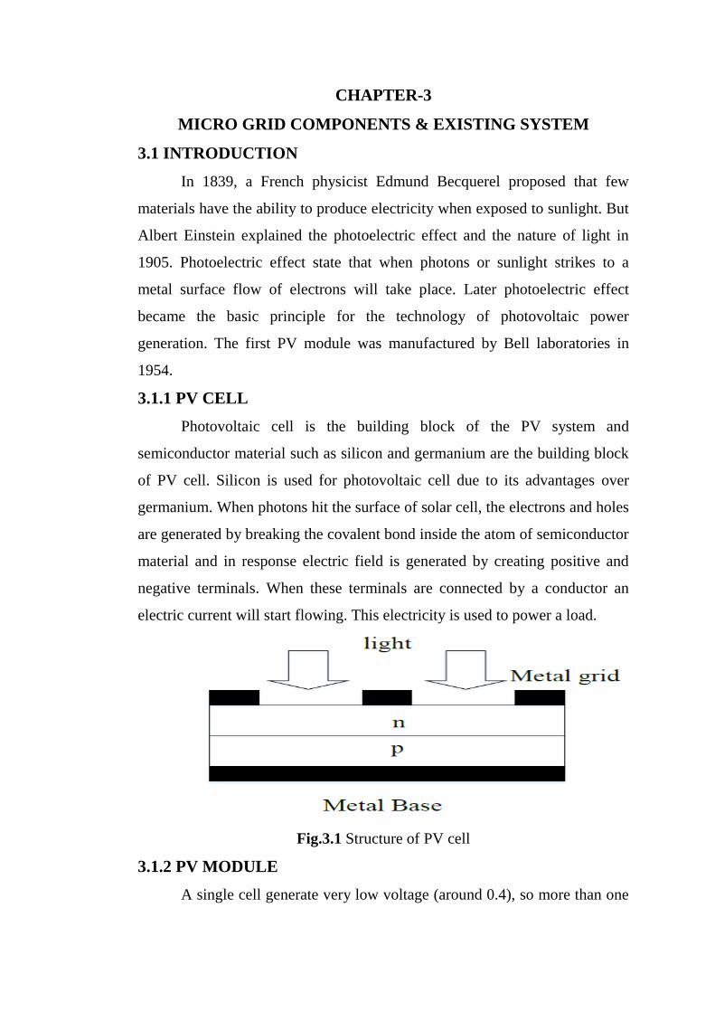
3.1.1 PV CELL
Photovoltaic cell is the building block of the PV system and
semiconductor material such as silicon and germanium are the building block
of PV cell. Silicon is used for photovoltaic cell due to its advantages over
germanium. When photons hit the surface of solar cell, the electrons and holes
are generated by breaking the covalent bond inside the atom of semiconductor
material and in response electric field is generated by creating positive and
negative terminals. When these terminals are connected by a conductor an
electric current will start flowing. This electricity is used to power a load.
Fig.3.1 Structure of PV cell
3.1.2 PV MODULE
A single cell generate very low voltage (around 0.4), so more than one

PV cells can be connected either in serial or in parallel or as a grid (both serial
and parallel) to form a PV module as shown in fig.3.3. When we need higher
voltage, we connect PV cell in series and if load demand is high current then
we connect PV cell in parallel. Usually there are 36 or 76 cells in general PV
modules. Module we are using having 54 cells. The front side of the module is
transparent usually buildup of low-iron and transparent glass material, and the
PV cell is encapsulated. The efficiency of a module is not as good as PV cell,
because the glass cover and frame reflects some amount of the incoming
radiation.
3.1.2 PV ARRAY
A photovoltaic array is simply an interconnection of several PV
modules in serial and/or parallel. The power generated by individual modules
may not be sufficient to meet the requirement of trading applications, so the
modules are secured in a grid form or as an array to gratify the load demand.
In an array, the modules are connected like as that of cells connected in a
module. While making a PV array, generally the modules are initially
connected in serial manner to obtain the desired voltage, and then strings so
obtained are connected in parallel in order to produce more current based on
the requirement.
Fig.3.2 Photovoltaic system
3.3 WORKING OF PV CELL
The basic theory involved in working of an individual PV cell is the
Photoelectric effect according to which, when a photon particle hits a PV cell,
after receiving energy from sunbeam the electrons of the semiconductor get
excited and hop to the conduction band from the valence band and become

free to move. Movement of electrons create positive and negative terminal
and also create potential difference across these two terminals. When an
external circuit is connected between these terminals an electric current start
flowing through the circuit.
Fig 3.3 Working of PV cell
3.4 MODELING OF PV CELL
The photovoltaic system converts sunlight directly to electricity
without having any disastrous effect on our environment. The basic segment
of PV array is PV cell, which is just a simple p-n junction device. The fig.3.4
manifests the equivalent circuit of PV cell . Equivalent circuit has a current
source (photocurrent), a diode parallel to it, a resistor in series describing an
internal resistance to the flow of current and a shunt resistance which
expresses a leakage current. The current supplied to the load can be given as.
Where
IPV–Photocurrent current,
IO–diode’s Reverse saturation current,
V–Voltage across the diode,
a– Ideality factor
VT –Thermal voltage
Rs– Series resistance
Rp–Shunt resistance
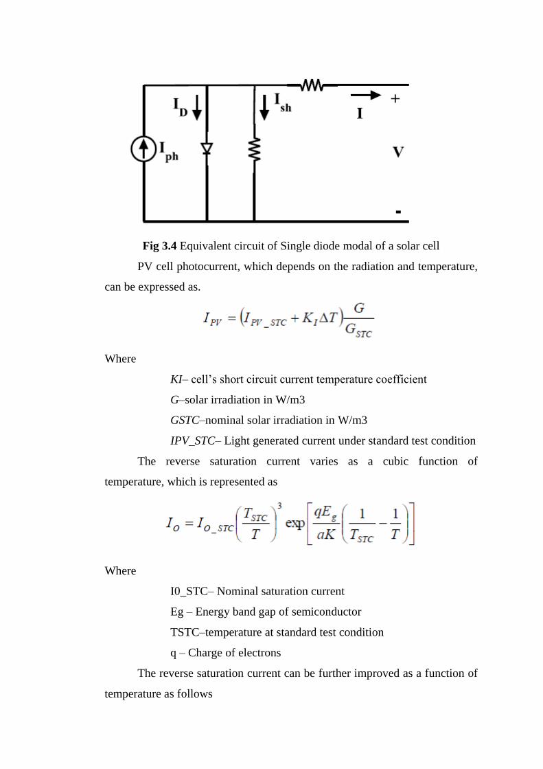
Fig 3.4 Equivalent circuit of Single diode modal of a solar cell
PV cell photocurrent, which depends on the radiation and temperature,
can be expressed as.
Where
KI– cell’s short circuit current temperature coefficient
G–solar irradiation in W/m3
GSTC–nominal solar irradiation in W/m3
IPV_STC– Light generated current under standard test condition
The reverse saturation current varies as a cubic function of
temperature, which is represented as
Where
I0_STC– Nominal saturation current
Eg – Energy band gap of semiconductor
TSTC–temperature at standard test condition
q – Charge of electrons
The reverse saturation current can be further improved as a function of
temperature as follows
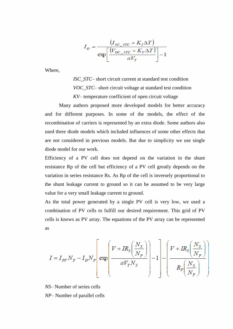
Where,
ISC_STC– short circuit current at standard test condition
VOC_STC– short circuit voltage at standard test condition
KV– temperature coefficient of open circuit voltage
Many authors proposed more developed models for better accuracy
and for different purposes. In some of the models, the effect of the
recombination of carriers is represented by an extra diode. Some authors also
used three diode models which included influences of some other effects that
are not considered in previous models. But due to simplicity we use single
diode model for our work.
Efficiency of a PV cell does not depend on the variation in the shunt
resistance Rp of the cell but efficiency of a PV cell greatly depends on the
variation in series resistance Rs. As Rp of the cell is inversely proportional to
the shunt leakage current to ground so it can be assumed to be very large
value for a very small leakage current to ground.
As the total power generated by a single PV cell is very low, we used a
combination of PV cells to fulfill our desired requirement. This grid of PV
cells is knows as PV array. The equations of the PV array can be represented
as
NS– Number of series cells
NP– Number of parallel cells
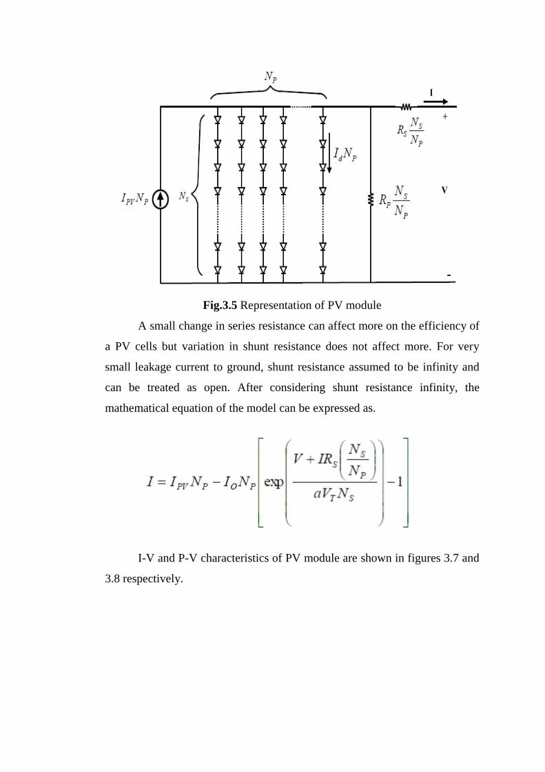
Fig.3.5 Representation of PV module
A small change in series resistance can affect more on the efficiency of
a PV cells but variation in shunt resistance does not affect more. For very
small leakage current to ground, shunt resistance assumed to be infinity and
can be treated as open. After considering shunt resistance infinity, the
mathematical equation of the model can be expressed as.
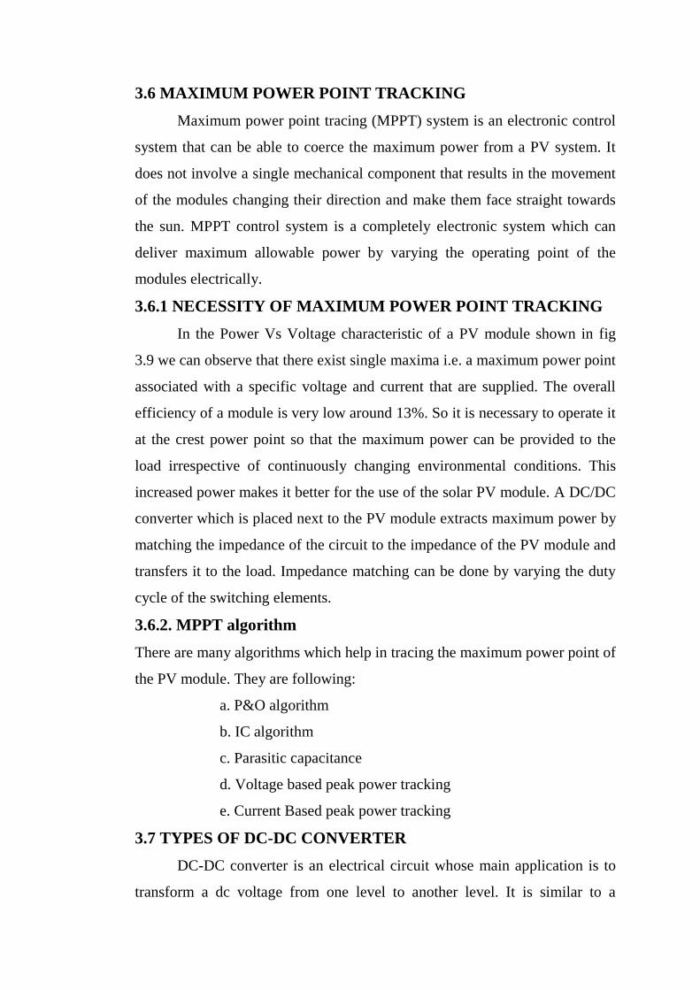
I-V and P-V characteristics of PV module are shown in figures 3.7 and
3.8 respectively.
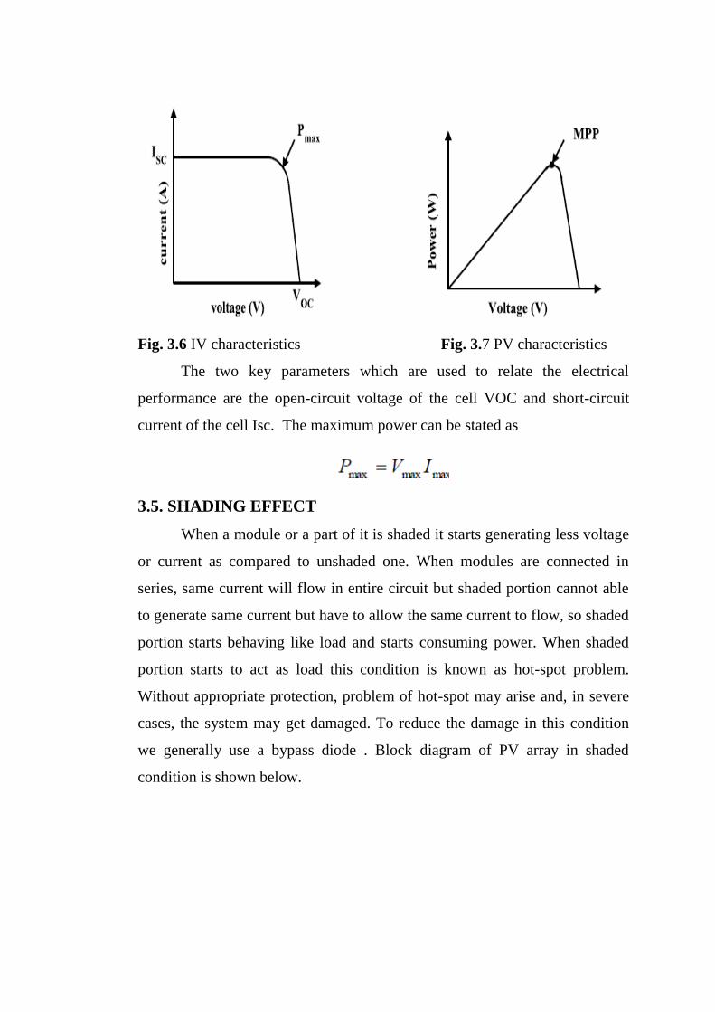
Fig. 3.6 IV characteristics Fig. 3.7 PV characteristics
The two key parameters which are used to relate the electrical
performance are the open-circuit voltage of the cell VOC and short-circuit
current of the cell Isc. The maximum power can be stated as
3.5. SHADING EFFECT
When a module or a part of it is shaded it starts generating less voltage
or current as compared to unshaded one. When modules are connected in
series, same current will flow in entire circuit but shaded portion cannot able
to generate same current but have to allow the same current to flow, so shaded
portion starts behaving like load and starts consuming power. When shaded
portion starts to act as load this condition is known as hot-spot problem.
Without appropriate protection, problem of hot-spot may arise and, in severe
cases, the system may get damaged. To reduce the damage in this condition
we generally use a bypass diode . Block diagram of PV array in shaded
condition is shown below.

Fig 3.8 PV Array in Shaded condition
Due to partial shading or total shading PV characteristic become more
non-linear, having more than one maximum power point. So for this condition
tracking of the maximum power point become very tedious. We can easily see
the effect of shading on PV characteristics in the fig shown below.
Fig. 3.9 Effect of partial shading on I-V & P-V characteristics
There is wastage of power due to the loss contributed by reverse current
which results in overheating of shaded cell.
3.6 MAXIMUM POWER POINT TRACKING
Maximum power point tracing (MPPT) system is an electronic control
system that can be able to coerce the maximum power from a PV system. It
does not involve a single mechanical component that results in the movement
of the modules changing their direction and make them face straight towards
the sun. MPPT control system is a completely electronic system which can
deliver maximum allowable power by varying the operating point of the
modules electrically.
3.6.1 NECESSITY OF MAXIMUM POWER POINT TRACKING
In the Power Vs Voltage characteristic of a PV module shown in fig
3.9 we can observe that there exist single maxima i.e. a maximum power point
associated with a specific voltage and current that are supplied. The overall
efficiency of a module is very low around 13%. So it is necessary to operate it
at the crest power point so that the maximum power can be provided to the
load irrespective of continuously changing environmental conditions. This
increased power makes it better for the use of the solar PV module. A DC/DC
converter which is placed next to the PV module extracts maximum power by
matching the impedance of the circuit to the impedance of the PV module and
transfers it to the load. Impedance matching can be done by varying the duty
cycle of the switching elements.
3.6.2. MPPT algorithm
There are many algorithms which help in tracing the maximum power point of
the PV module. They are following:
a. P&O algorithm
b. IC algorithm
c. Parasitic capacitance
d. Voltage based peak power tracking
e. Current Based peak power tracking
3.7 TYPES OF DC-DC CONVERTER
DC-DC converter is an electrical circuit whose main application is to
transform a dc voltage from one level to another level. It is similar to a
transformer in AC source, it can able to step the voltage level up or down. The
variable dc voltage level can be regulated by controlling the duty ratio (on-off
time of a switch) of the converter.
There are various types of dc-dc converters that can be used to
transform the level of the voltage as per the supply availability and load
requirement. Some of them are discussed below.
1. Buck converter
3. Boost converter
3. Buck-Boost converter
Each of them is explained below.
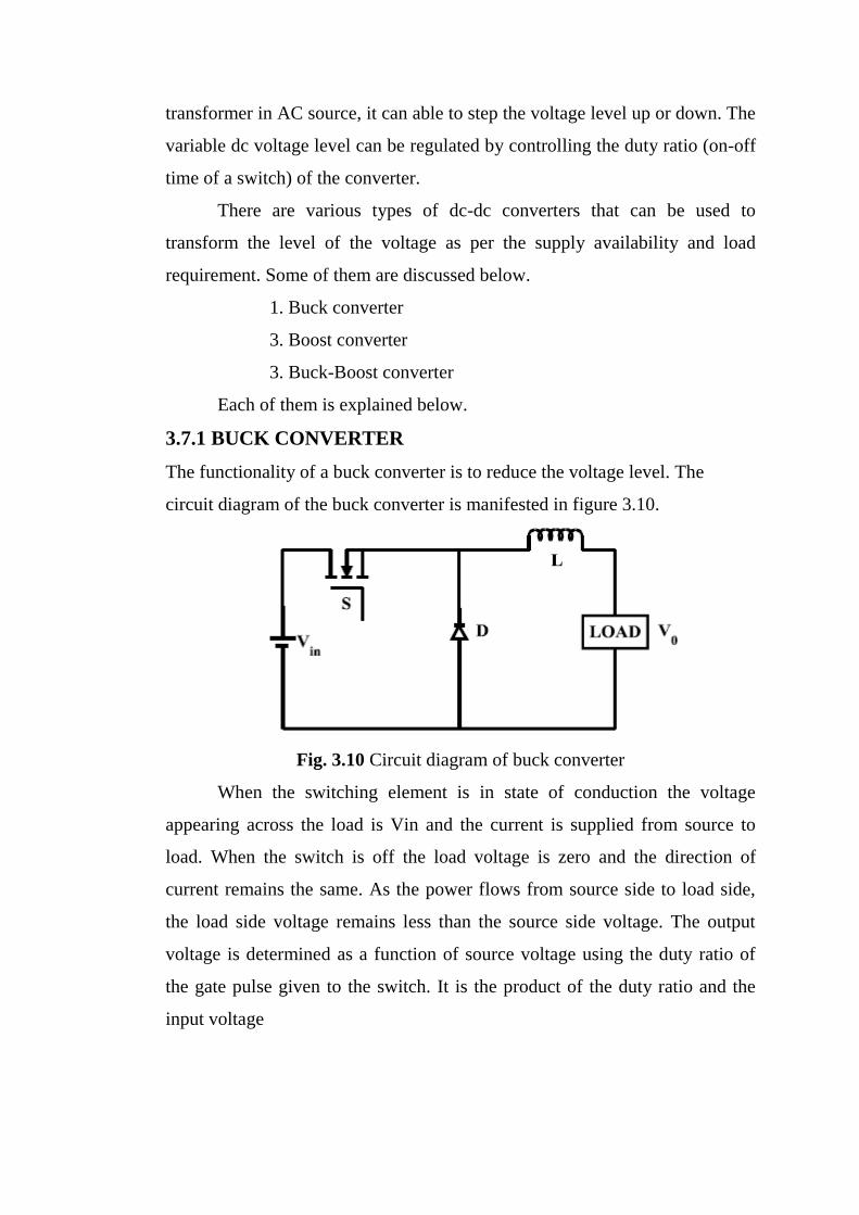
3.7.1 BUCK CONVERTER
The functionality of a buck converter is to reduce the voltage level. The
circuit diagram of the buck converter is manifested in figure 3.10.
Fig. 3.10 Circuit diagram of buck converter
When the switching element is in state of conduction the voltage
appearing across the load is Vin and the current is supplied from source to
load. When the switch is off the load voltage is zero and the direction of
current remains the same. As the power flows from source side to load side,
the load side voltage remains less than the source side voltage. The output
voltage is determined as a function of source voltage using the duty ratio of
the gate pulse given to the switch. It is the product of the duty ratio and the
input voltage
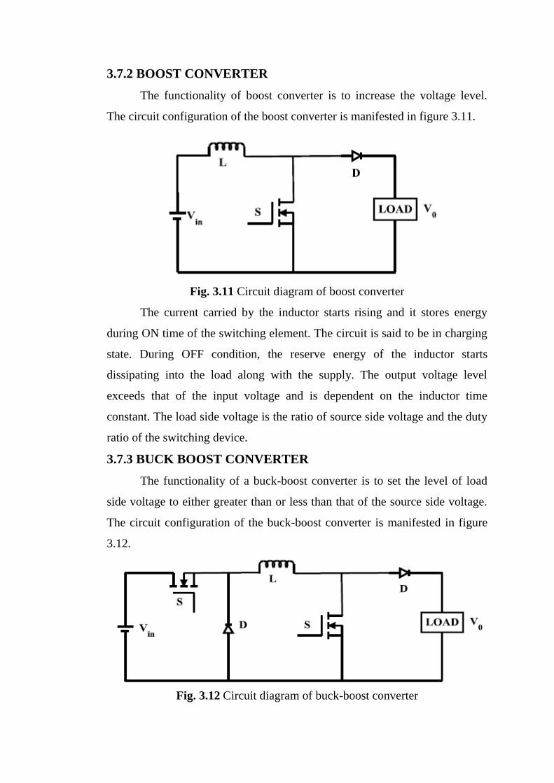
3.7.2 BOOST CONVERTER
The functionality of boost converter is to increase the voltage level.
The circuit configuration of the boost converter is manifested in figure 3.11.
Fig. 3.11 Circuit diagram of boost converter
The current carried by the inductor starts rising and it stores energy
during ON time of the switching element. The circuit is said to be in charging
state. During OFF condition, the reserve energy of the inductor starts
dissipating into the load along with the supply. The output voltage level
exceeds that of the input voltage and is dependent on the inductor time
constant. The load side voltage is the ratio of source side voltage and the duty
ratio of the switching device.
3.7.3 BUCK BOOST CONVERTER
The functionality of a buck-boost converter is to set the level of load
side voltage to either greater than or less than that of the source side voltage.
The circuit configuration of the buck-boost converter is manifested in figure
3.12.
Fig. 3.12 Circuit diagram of buck-boost converter

When the switches are in the state of conduction, the current carried by
the inductor starts rising and it stores energy. The circuit is said to be in
charging state. While the switches are in the OFF state, this stored energy of
the inductor is dissipated to the load through the diodes. The output voltage
can be varied based on the On-time of the switches.
The buck-boost converter acts as both buck and boost converters
depending on the duty cycle of the switches. For the duty ratio less than 50%
it acts as a buck converter and for the duty ratio exceeds than 50% it acts as
boost converter.
3.8 WIND ENERGY CONVERSION SYSTEMS
Wind energy conversion systems (WECS) convert the kinetic
energy of the wind into electricity or other forms of energy. Wind power
generation has experienced a tremendous growth in the past decade, and has
been recognized as an environmentally friendly and economically competitive
means of electric power generation. The availability of renewable energy
sources has strong daily and seasonal patterns and the power demand by the
consumers could have a very different characteristic. Therefore, it is difficult
to operate a power system installed with only renewable generation units due
to the characteristic differences and the high uncertainty in the availability of
the renewable energy sources. Modern wind turbines have lot of
commercially available topologies, among that the variable speed wind
turbines are more attractive, as they can extract maximum power at different
wind velocities, and thus, reduce the mechanical stress on WECS by
absorbing the wind power fluctuations. For a variable-speed wind turbine the
generator is controlled by power electronic equipment.
The advantages of Wind Energy over other Non-Conventional Sources are:
It is available throughout the day unlike solar energy.
After solar energy it is the second largest source of non-
conventional source of energy
In India during the mid summer due to the lack of hydel power
generation there is desperate need for energy. This can be met to
some extent by wind energy as there are very high winds during
this period.
By using photo voltaic, the power generated is DC .So it must be
converted to AC to feed it to grid. But by using wind energy we can
directly produce AC.
In coastal areas, the cost of power generation from wind has
become lower than diesel power and compared to thermal power.
From the study of wind distribution, it is estimated that about 27%
of the land surface is exposed to an annual wind speed higher than
18.36kmph at 10m above the surface.
3.1 WIND TURBINES
A wind turbine is a rotating machine which converts the kinetic
energy of wind into mechanical energy. The mechanical energy is then
converted into electricity by using wind generator. Wind turbines can be
separated into two types based by the axis in which the turbine rotates.
Turbines that rotate around a horizontal axis are more common. Vertical-axis
turbines are less frequently used.
3.1.1 Modelling of Wind Turbine
The aerodynamic power of wind is converted into mechanical
energy by wind turbine i.e. the blades obtain kinetic energy from the wind
which is transformed to mechanical torque at the rotor shaft of the wind
turbine. The wind power can be calculated by the following equation
Pt= 1/2ρCpAV3 (3.1)
Where
Ptis the rotor mechanical power (W)
V the wind speed (m/s)
Α= π R2
the rotor surface (m2
)
R is the rotor radius (m)
ρ the air density (kg/m3
)
Cp is the power coefficient.

The rotor aerodynamic power coefficient, Cp, is the function of blade pitch
angle (β) and tip speed ration (λ)
λ= Tip speed/Wind speed
λ =ωrR/V (3.2)
Sub eqn (3.2) in (3.1) we get
Pt = 1\2 Cp (λ)ρA(R/λ)3ω3 (3.3)
The output torque of the wind turbine Tt is calculated by the following
equation
Tt = 1/2 ρCpA(V/λ) (3.4)
Variable speed turbines are made to capture the maximum energy
of the wind by operating them at a blade speed that gives the optimum tip
speed ratio. This may be done by changing the speed of the turbine in
proportion to the change in wind speed. Figure 3.1 shows how variable speed
operation will allow a wind turbine to capture more energy from the wind.
Fig 3.1 Power speed characteristics
3.1.2 Horizontal Axis Wind Turbines
Horizontal-axis wind turbines (HAWT) have the main rotor shaft
and electrical generator at the top of a tower, and must be pointed into the
wind. Most have a gearbox, which turns the slow rotation of the blades into a
quicker rotation that is more suitable to drive an electrical generator. Since a
tower produces turbulence behind it, the turbine is usually pointed upwind of
the tower. Turbine blades are made stiff to prevent the blades from being
pushed into the tower by high winds. Additionally, the blades are placed a
considerable distance in front of the tower and are sometimes tilted up a small
amount. Downwind machines have been built, despite the problem of
turbulence, because they don't need an additional mechanism for keeping
them in line with the wind, and because in high winds the 3 blades can be
allowed to bend which reduces their swept area and thus their wind resistance.
Since cyclic (that is repetitive) turbulence may lead to fatigue failures most
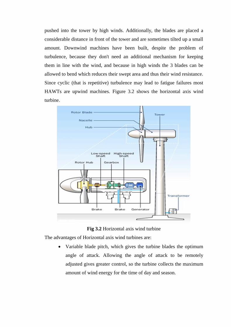
HAWTs are upwind machines. Figure 3.2 shows the horizontal axis wind
turbine.
Fig 3.2 Horizontal axis wind turbine
The advantages of Horizontal axis wind turbines are:
Variable blade pitch, which gives the turbine blades the optimum
angle of attack. Allowing the angle of attack to be remotely
adjusted gives greater control, so the turbine collects the maximum
amount of wind energy for the time of day and season.
The tall tower base allows access to stronger wind in sites with
wind shear. In some wind shear sites, every ten meters up, the wind
speed can increase by 20% and the power output by 34%.
High efficiency, since the blades always moves perpendicularly to
the wind, receiving power through the whole rotation. In contrast,
all vertical axis wind turbines, and most proposed airborne wind
turbine designs, involve various types of reciprocating actions,
requiring airfoil surfaces to backtrack against the wind for part of
the cycle. Backtracking against the wind leads to inherently lower
efficiency.
The disadvantages of Horizontal axis wind turbines are:
The tall towers and blades up to 90 meters long are difficult to
transport. Transportation can now cost 20% of equipment costs.
Tall HAWTs are difficult to install, needing very tall and expensive
cranes and skilled operators.
Massive tower construction is required to support the heavy blades,
gearbox, and generator.
Reflections from tall HAWTs may affect side lobes of radar
installations creating signal clutter, although filtering can suppress
it.
Downwind variants suffer from fatigue and structural failure caused
by turbulence when a blade passes through the tower's wind shadow
(for this reason, the majority of HAWTs use an upwind design,
with the rotor facing the wind in front of the tower).
HAWTs require an additional yaw control mechanism to turn the
blades toward the wind.
3.1.3 Vertical Axis Wind Turbines
Vertical-axis wind turbines (or VAWTs) have the main rotor shaft
arranged vertically. Key advantages of this arrangement are that the turbine
does not need to be pointed into the wind to be effective. This is an advantage
on sites where the wind direction is highly variable. VAWTs can utilize winds
from varying directions. With a vertical axis, the generator and gearbox can
be placed near the ground, so the tower doesn't need to support it, and it is
more accessible for maintenance. Drawbacks are that some designs produce
pulsating torque. Drag may be created when the blade rotates into the wind.
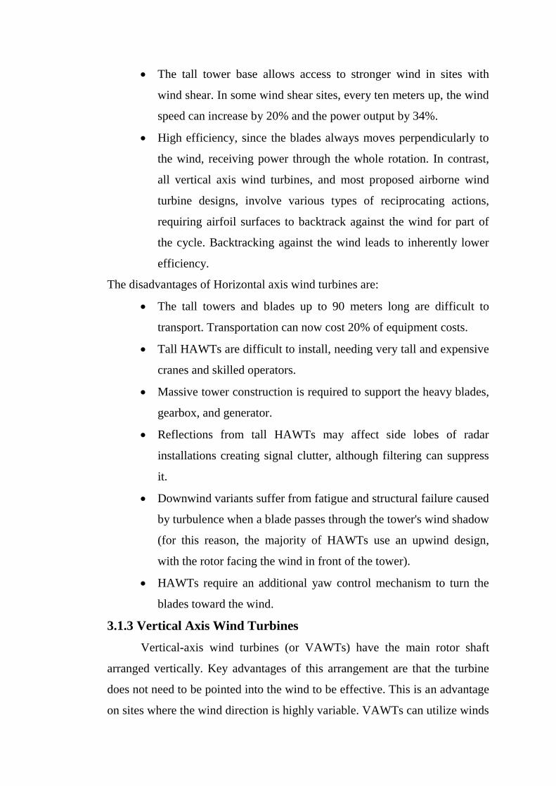
Figure 3.3 shows the vertical axis wind turbines.
Fig 3.3 Vertical axis wind turbine
The advantages of Vertical-axis wind turbines are:
A massive tower structure is less frequently used, as VAWTs are more
frequently mounted with the lower bearing mounted near the ground.
Designs without yaw mechanisms are possible with fixed pitch
rotor designs.
A VAWT can be located nearer the ground, making it easier to
maintain the moving parts.
VAWTs have lower wind startup speeds than HAWTs. Typically,
they start creating electricity at 6 M.P.H. (10 km/h).
VAWTs may have a lower noise signature.
The disadvantages of Vertical-axis wind turbines are:
Most VAWTs produce energy at only 50% of the efficiency of
HAWTs in large part because of the additional drag that they have
as their blades rotate into the wind.

While VAWTs' parts are located on the ground, they are also
located under the weight of the structure above it, which can make
changing out parts nearly impossible without dismantling the
structure if not designed properly.
Having rotors located close to the ground where wind speeds are
lower due to wind shear, VAWTs may not produce as much energy
at a given site as a HAWT with the same footprint or height.
3.1.4 Wind Turbine Glossary
The Figure 3.4 shows the parts present in a wind turbine. The
details of the parts are showed and explained.
Figure 3.4 Parts of wind turbine
Anemometer: Measures the wind speed and transmits wind speed data to
the controller.
Blades: Most turbines have either two or three blades. Wind blowing over
the blades causes the blades to "lift" and rotate.
Brake: A disc brake which can be applied mechanically, electrically, or
hydraulically to stop the rotor in emergencies.
Controller: The controller starts up the machine at wind speeds of about 8 to
16 miles per hour (mph) and shuts off the machine at about 65 mph. Turbines
cannot operate at wind speeds above about 65 mph because their generators
could overheat.
Gear box:Gears connect the low-speed shaft to the high-speed shaft and
increase the rotational speeds from about 30 to 60 rotations per minute (rpm)
to about 1200 to 1500 rpm, the rotational speed required by most generators to
produce electricity. The gear box is a costly (and heavy) part of the wind
turbine and engineers are exploring "direct-drive" generators that operate at
lower rotational speeds and don't need gear boxes.
Generator:Usually an off-the-shelf induction generator that produces 60-
cycle AC electricity.
High-speed shaft: It is used to Drives the generator.
Low-speed shaft:The rotor turns the low-speed shaft at about 30 to 60
rotations per minute.
Nacelle:The rotor attaches to the nacelle, which sits atop the tower and
includes the gear box, low- and high-speed shafts, generator, controller, and
brake. A cover protects the components inside the nacelle. Some nacelles are
large enough for a technician to stand inside while working.
Pitch: Blades are turned, or pitched, out of the wind to keep the rotor from
turning in winds that are too high or too low to produce electricity.
Rotor: The blades and the hub together are called the rotor.
Tower: Towers are made from tubular steel or steel lattice. Because wind
speed increases with height, taller towers enable turbines to capture more
energy and generate more electricity.
Wind direction: This is an "upwind" turbine, so-called because it operates
facing into the wind. Other turbines are designed to run "downwind", facing
away from the wind.
Wind vane: Measures wind direction and communicates with the yaw drive
to orient the turbine properly with respect to the wind.
Yaw drive: Upwind turbines face into the wind, the yaw drive is used to
keep the rotor facing into the wind as the wind direction changes. Downwind
turbines don't require a yaw drive.
Wind turbines typically have two degrees of freedom to optimize
power generation.
1. The ability to change their yaw or compass orientation by turning
the entire nacelle unit so the rotor is pointed directly into the wind.
This process is controlled by wind direction information from
nearby wind vanes which are located to minimize the effect due to
wake turbulence from the wind turbines.
2. The pitch of the blades which can be changed to keep a near-
constant rotation rate under varying wind speeds, where the rotation
rate is chosen to optimize the power-generation efficiency of the
turbine. Another purpose of both the blade pitch control and yaw
Mechanisms is to act as a brake under extremely strong wind
condition. Cut- in speed: The lowest wind speed at which a wind
turbine begins producing usable power is called cut-in speed. It is
about 3m/s Cut-out speed: The highest wind speed at which a wind
turbine stops producing power is called cut-out speed. It is about
30m/s.
3.2 WIND SPEED CONTROL
3.2.1 Power Control
A wind turbine is designed to produce a maximum of power at wide
spectrum of wind speeds.
The wind turbines have three modes of operation:
• Below rated wind speed operation
• Around rated wind speed operation
• Above rated wind speed operation
If the rated wind speed is exceeded the power has to be limited.
There are various ways to achieve this.
3.2.2 Stall Control
Stalling works by increasing the angle at which the relative wind
strikes the blades (angle of attack), and it reduces the induced drag (drag
associated with lift). Stalling is simple because it can be made to happen
passively (it increases automatically when the winds speed up), but it
increases the cross-section of the blade face-on to the wind, and thus the
ordinary drag. A fully stalled turbine blade, when stopped, has the flat side of
the blade facing directly into the wind. A fixed-speed HAWT inherently
increases its angle of attack at higher wind speed as the blades speed up. A
natural strategy, then, is to allow the blade to stall when the wind speed
increases. This technique was successfully used on many early HAWTs.
However, on some of these blade sets, it was observed that the degree of blade
pitch tended to increase audible noise levels.
3.2.3 Pitch Control
Furling works by decreasing the angle of attack, which reduces the
induced drag from the lift of the rotor, as well as the cross-section. One major
problem in designing wind turbines is getting the blades to stall or furl quickly
enough should a gust of wind cause sudden acceleration. A fully furled
turbine blade, when stopped, has the edge of the blade facing into the wind.
Standard modern turbines all pitch the blades in high winds. Since pitching
requires acting against the torque on the blade, it requires some form of pitch
angle control. Many turbines use hydraulic systems. These systems are
usually spring loaded, so that if hydraulic power fails, the blades
automatically furl. Other turbines use an electric servomotor for every rotor
blade. They have a small battery-reserve in case of an electric-grid
breakdown. Small wind turbines (fewer than 50 kW) with variable-pitching
generally use systems operated by centrifugal force, either by flyweights or
geometric design, and employ no electric or hydraulic controls.
3.3 GENERATOR
The working principle of a wind turbine encompasses two
conversion processes, which are carried out by its components, the rotor that
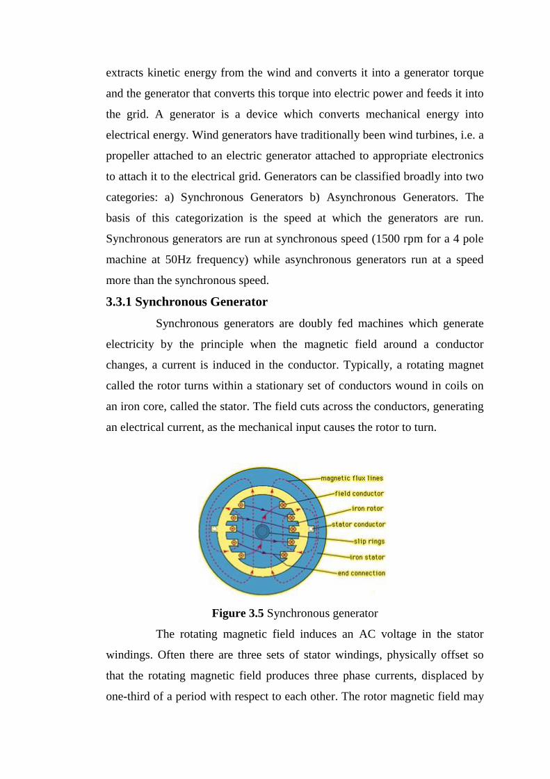
extracts kinetic energy from the wind and converts it into a generator torque
and the generator that converts this torque into electric power and feeds it into
the grid. A generator is a device which converts mechanical energy into
electrical energy. Wind generators have traditionally been wind turbines, i.e. a
propeller attached to an electric generator attached to appropriate electronics
to attach it to the electrical grid. Generators can be classified broadly into two
categories: a) Synchronous Generators b) Asynchronous Generators. The
basis of this categorization is the speed at which the generators are run.
Synchronous generators are run at synchronous speed (1500 rpm for a 4 pole
machine at 50Hz frequency) while asynchronous generators run at a speed
more than the synchronous speed.
3.3.1 Synchronous Generator
Synchronous generators are doubly fed machines which generate
electricity by the principle when the magnetic field around a conductor
changes, a current is induced in the conductor. Typically, a rotating magnet
called the rotor turns within a stationary set of conductors wound in coils on
an iron core, called the stator. The field cuts across the conductors, generating
an electrical current, as the mechanical input causes the rotor to turn.
Figure 3.5 Synchronous generator
The rotating magnetic field induces an AC voltage in the stator
windings. Often there are three sets of stator windings, physically offset so
that the rotating magnetic field produces three phase currents, displaced by
one-third of a period with respect to each other. The rotor magnetic field may
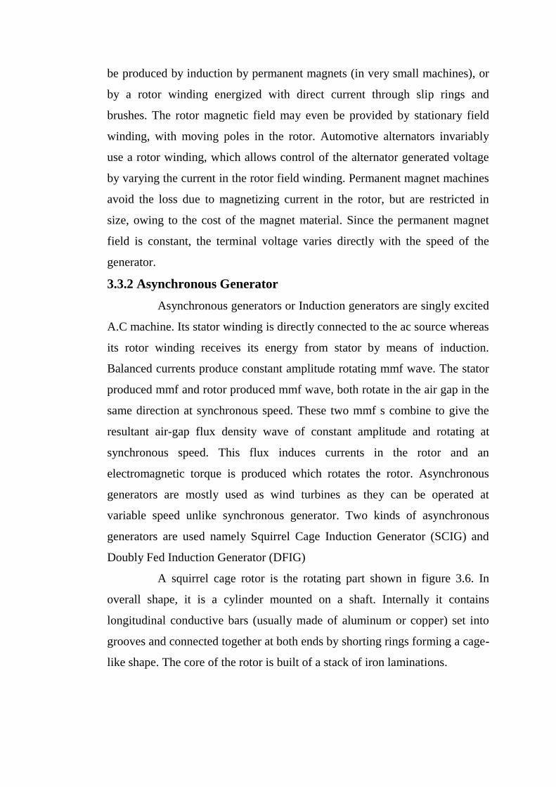
be produced by induction by permanent magnets (in very small machines), or
by a rotor winding energized with direct current through slip rings and
brushes. The rotor magnetic field may even be provided by stationary field
winding, with moving poles in the rotor. Automotive alternators invariably
use a rotor winding, which allows control of the alternator generated voltage
by varying the current in the rotor field winding. Permanent magnet machines
avoid the loss due to magnetizing current in the rotor, but are restricted in
size, owing to the cost of the magnet material. Since the permanent magnet
field is constant, the terminal voltage varies directly with the speed of the
generator.
3.3.2 Asynchronous Generator
Asynchronous generators or Induction generators are singly excited
A.C machine. Its stator winding is directly connected to the ac source whereas
its rotor winding receives its energy from stator by means of induction.
Balanced currents produce constant amplitude rotating mmf wave. The stator
produced mmf and rotor produced mmf wave, both rotate in the air gap in the
same direction at synchronous speed. These two mmf s combine to give the
resultant air-gap flux density wave of constant amplitude and rotating at
synchronous speed. This flux induces currents in the rotor and an
electromagnetic torque is produced which rotates the rotor. Asynchronous
generators are mostly used as wind turbines as they can be operated at
variable speed unlike synchronous generator. Two kinds of asynchronous
generators are used namely Squirrel Cage Induction Generator (SCIG) and
Doubly Fed Induction Generator (DFIG)
A squirrel cage rotor is the rotating part shown in figure 3.6. In
overall shape, it is a cylinder mounted on a shaft. Internally it contains
longitudinal conductive bars (usually made of aluminum or copper) set into
grooves and connected together at both ends by shorting rings forming a cage-
like shape. The core of the rotor is built of a stack of iron laminations.
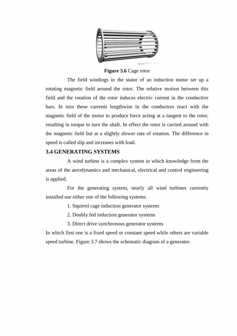
Figure 3.6 Cage rotor
The field windings in the stator of an induction motor set up a
rotating magnetic field around the rotor. The relative motion between this
field and the rotation of the rotor induces electric current in the conductive
bars. In turn these currents lengthwise in the conductors react with the
magnetic field of the motor to produce force acting at a tangent to the rotor,
resulting in torque to turn the shaft. In effect the rotor is carried around with
the magnetic field but at a slightly slower rate of rotation. The difference in
speed is called slip and increases with load.
3.4 GENERATING SYSTEMS
A wind turbine is a complex system in which knowledge from the
areas of the aerodynamics and mechanical, electrical and control engineering
is applied.
For the generating system, nearly all wind turbines currently
installed use either one of the following systems.
1. Squirrel cage induction generator systems
2. Doubly fed induction generator systems
3. Direct drive synchronous generator systems
In which first one is a fixed speed or constant speed while others are variable
speed turbine. Figure 3.7 shows the schematic diagram of a generator.
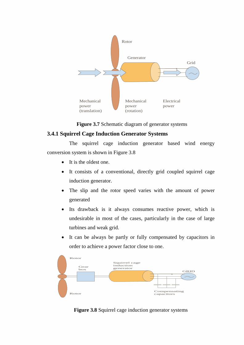
Figure 3.7 Schematic diagram of generator systems
3.4.1 Squirrel Cage Induction Generator Systems
The squirrel cage induction generator based wind energy
conversion system is shown in Figure 3.8
It is the oldest one.
It consists of a conventional, directly grid coupled squirrel cage
induction generator.
The slip and the rotor speed varies with the amount of power
generated
Its drawback is it always consumes reactive power, which is
undesirable in most of the cases, particularly in the case of large
turbines and weak grid.
It can be always be partly or fully compensated by capacitors in
order to achieve a power factor close to one.
GRID
Compensating
capacitors
Squirrel cage
induction
generatorGear
box
Rotor
Rotor
Figure 3.8 Squirrel cage induction generator systems
Rotor
Generator
Grid
Mechanical
power
(translation)
Mechanical
power
(rotation)
Electrical
power

3.4.2 Doubly Fed Induction Generator Systems
The doubly fed induction generator based wind energy conversion
system is shown in Figure 3.9.
It is a variable speed turbine
In this case a back-to-back voltage source converter feeds the three-
phase rotor winding. So the mechanical and electrical rotor
frequencies are decoupled and the electrical stator and rotor
frequency can match, independently of the mechanical rotor speed.
GRID
Doubly fed
induction
generatorGear
box
Rotor
Rotor
converter
Figure 3.9 Doubly fed induction generator system
3.4.2.1 Operating principle of DFIG
Power flow diagram of DFIG is shown in figure 3.10. The stator is
directly connected to the AC mains, whilst the wound rotor is fed from the
Power Electronics Converter via slip rings to allow DIFG to operate at a
variety of speeds in response to changing wind speed. Indeed, the basic
concept is to interpose a frequency converter between the variable frequency
induction generator and fixed frequency grid. The DC capacitor linking stator-
and rotor-side converters allows the storage of power from induction
generator for further generation. To achieve full control of grid current, the
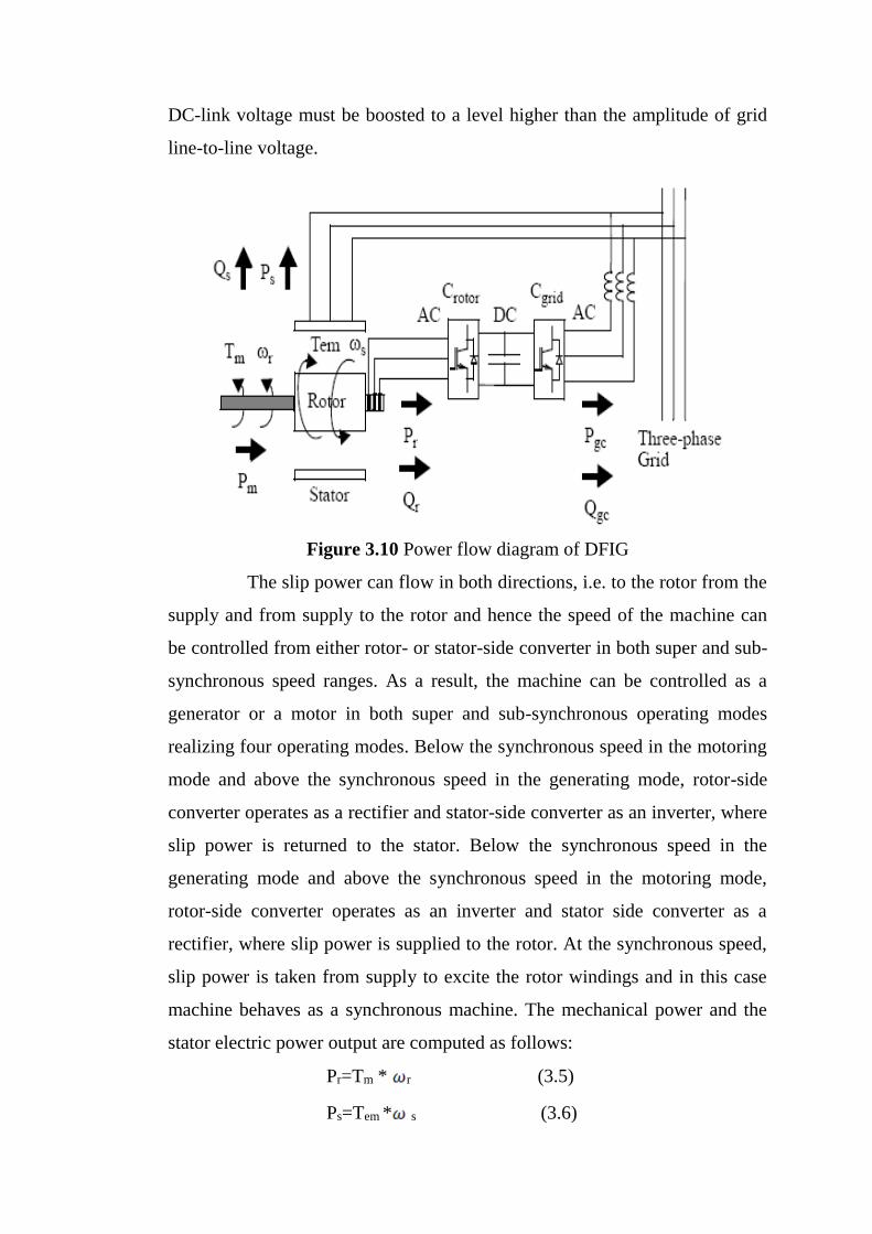
DC-link voltage must be boosted to a level higher than the amplitude of grid
line-to-line voltage.
Figure 3.10 Power flow diagram of DFIG
The slip power can flow in both directions, i.e. to the rotor from the
supply and from supply to the rotor and hence the speed of the machine can
be controlled from either rotor- or stator-side converter in both super and sub-
synchronous speed ranges. As a result, the machine can be controlled as a
generator or a motor in both super and sub-synchronous operating modes
realizing four operating modes. Below the synchronous speed in the motoring
mode and above the synchronous speed in the generating mode, rotor-side
converter operates as a rectifier and stator-side converter as an inverter, where
slip power is returned to the stator. Below the synchronous speed in the
generating mode and above the synchronous speed in the motoring mode,
rotor-side converter operates as an inverter and stator side converter as a
rectifier, where slip power is supplied to the rotor. At the synchronous speed,
slip power is taken from supply to excite the rotor windings and in this case
machine behaves as a synchronous machine. The mechanical power and the
stator electric power output are computed as follows:
Pr=Tm * r (3.5)
Ps=Tem * s (3.6)
For a loss less generator the mechanical equation is:
J =Tm - Tem (3.7)
In steady-state at fixed speed for a loss less generator
Tm =Tem and Pm= Ps+Pr (3.8)
and it follows that:
Pr=Pm - Ps = Tm - r - Tem s = -sPs (3.9)
s = ( s - r)/ s is defined as the slip of the generator
Generally the absolute value of slip is much lower than 1 and,
consequently, Pr is only a fraction of Ps. Since Tm is positive for power
generation and since ωs is positive and constant for a constant frequency grid
voltage, the sign of Pr is a function of the slip sign. Pr is positive for negative
slip (speed greater than synchronous speed) and it is negative for positive slip
(speed lower than synchronous speed). For super synchronous speed
operation, Pr is transmitted to DC bus capacitor and tends to raise the DC
voltage. For sub-synchronous speed operation, Pr is taken out of DC bus
capacitor and tends to decrease the DC voltage. Cgrid is used to generate or
absorb the power Pgc in order to keep the DC voltage constant. In steady-state
for a lossless AC/DC/AC converter Pgc is equal to Pr and the speed of the
wind turbine is determined by the power Pr absorbed or generated by Crotor.
The phase-sequence of the AC voltage generated by Crotor is positive for sub-
synchronous speed and negative for super synchronous speed. The frequency
of this voltage is equal to the product of the grid frequency and the absolute
value of the slip. Crotor and Cgrid have the capability for generating or
absorbing reactive power and could be used to control the reactive power or
the voltage at the grid terminals.
3.4.3 Direct Drive Synchronous Generator Systems
Figure 3.11 shows the direct drive synchronous generator systems
In this case, generator is completely decoupled from the grid by a
power electronics converter connected to the stator winding.
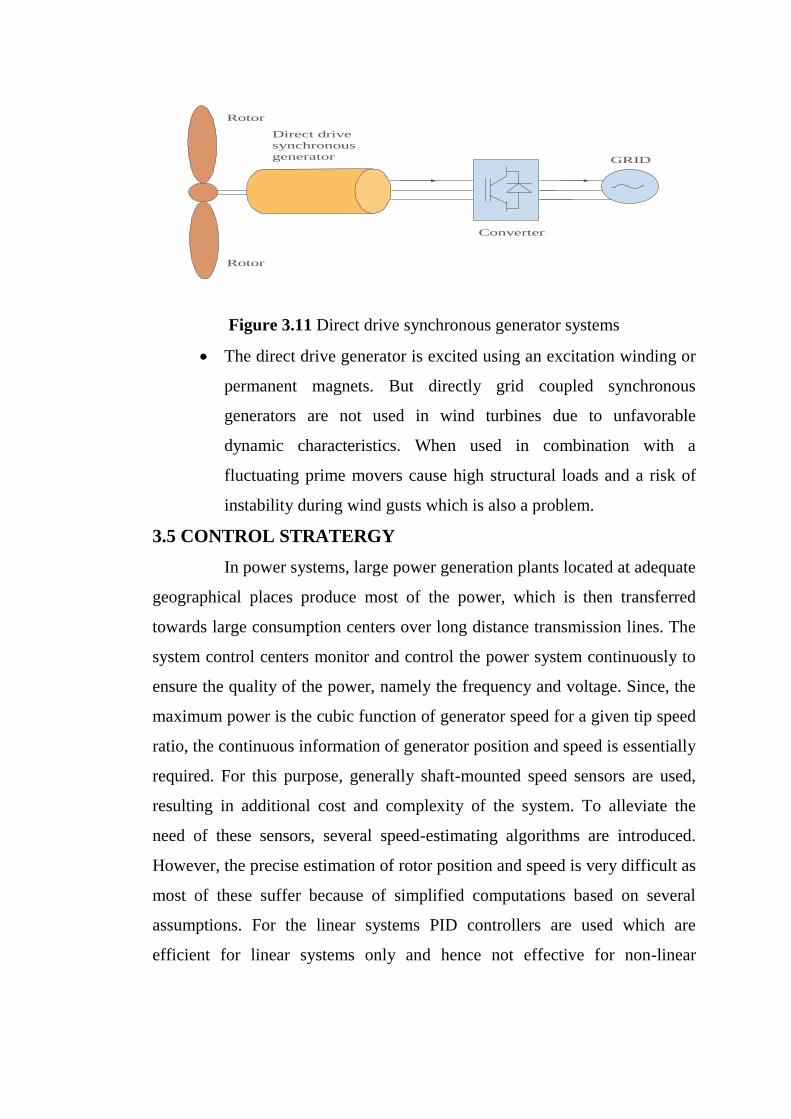
GRID
Direct drive
synchronous
generator
Rotor
Rotor
Converter
Figure 3.11 Direct drive synchronous generator systems
The direct drive generator is excited using an excitation winding or
permanent magnets. But directly grid coupled synchronous
generators are not used in wind turbines due to unfavorable
dynamic characteristics. When used in combination with a
fluctuating prime movers cause high structural loads and a risk of
instability during wind gusts which is also a problem.
3.5 CONTROL STRATERGY
In power systems, large power generation plants located at adequate
geographical places produce most of the power, which is then transferred
towards large consumption centers over long distance transmission lines. The
system control centers monitor and control the power system continuously to
ensure the quality of the power, namely the frequency and voltage. Since, the
maximum power is the cubic function of generator speed for a given tip speed
ratio, the continuous information of generator position and speed is essentially
required. For this purpose, generally shaft-mounted speed sensors are used,
resulting in additional cost and complexity of the system. To alleviate the
need of these sensors, several speed-estimating algorithms are introduced.
However, the precise estimation of rotor position and speed is very difficult as
most of these suffer because of simplified computations based on several
assumptions. For the linear systems PID controllers are used which are
efficient for linear systems only and hence not effective for non-linear

systems. Hence for non-linear systems Neuro fuzzy Logic System (FLS) is
used, it has the disadvantage of non adaptiveness.
Neuro and Neuro- Neuro fuzzy (NF) system based position and
speed estimator of DFIG has been proposed for wide range of speed operation
during variable speed condition. The NF architecture has well-known
advantages of modeling a highly non-linear system, as it combines the
capability of Neuro fuzzy reasoning in handling uncertainties and capability
of Artificial Neural Network (ANN) in learning from process. Neuro fuzzy
Logic allows making definite decisions based on ambiguous data. ANN tries
to incorporate human thinking process to solve problems without
mathematically modeling. Both of these methods can be used to solve
nonlinear problems. In contrast to Neuro fuzzy logic, ANN tries to apply the
thinking process in the human brain to solve problems. Hybrid intelligent
systems developed using these two methods called Neuro fuzzy Neural
Network (FNN) or Neuro-Neuro fuzzy System (NFS)) the disadvantages
found in both methods can be avoided and thus an efficient output can be
obtained.
3.5.1 Power Converter Control System
A device that converts dc power into ac power at desired output
voltage and frequency is called an Inverter. Voltage Source Inverter is one in
which the dc source has small or negligible impedance. In other words, a
voltage source inverter has a stiff voltage source at its input terminals. AC
loads may require constant or adjustable voltage at their input terminals.
When such loads are fed by inverters, it is essential that output voltage of the
inverters is so controlled as to fulfill the requirements of the ac loads. PWM
control is a method to control the output voltage that is widely in application.
In this method, a fixed dc input voltage is given to the inverter and a
controlled ac output voltage is obtained by adjusting the on and off periods of
the inverter components. The advantages possessed by PWM technique are as
under,
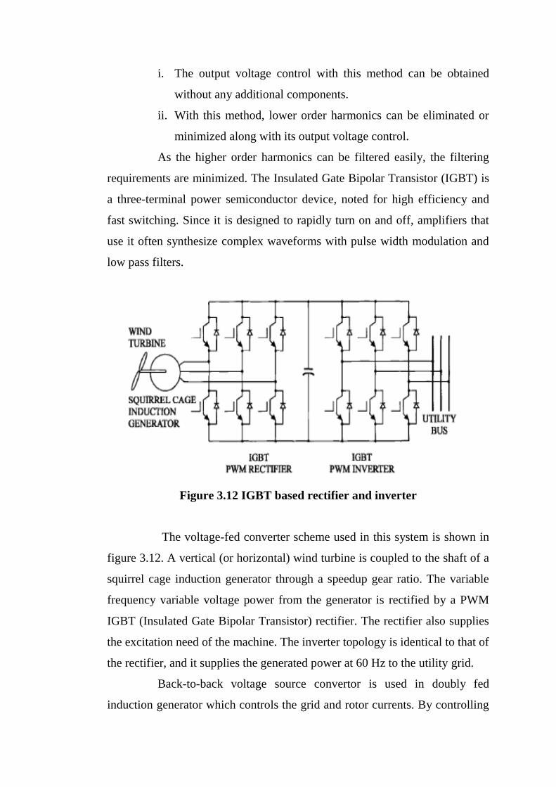
i. The output voltage control with this method can be obtained
without any additional components.
ii. With this method, lower order harmonics can be eliminated or
minimized along with its output voltage control.
As the higher order harmonics can be filtered easily, the filtering
requirements are minimized. The Insulated Gate Bipolar Transistor (IGBT) is
a three-terminal power semiconductor device, noted for high efficiency and
fast switching. Since it is designed to rapidly turn on and off, amplifiers that
use it often synthesize complex waveforms with pulse width modulation and
low pass filters.
Figure 3.12 IGBT based rectifier and inverter
The voltage-fed converter scheme used in this system is shown in
figure 3.12. A vertical (or horizontal) wind turbine is coupled to the shaft of a
squirrel cage induction generator through a speedup gear ratio. The variable
frequency variable voltage power from the generator is rectified by a PWM
IGBT (Insulated Gate Bipolar Transistor) rectifier. The rectifier also supplies
the excitation need of the machine. The inverter topology is identical to that of
the rectifier, and it supplies the generated power at 60 Hz to the utility grid.
Back-to-back voltage source convertor is used in doubly fed
induction generator which controls the grid and rotor currents. By controlling
the rotor currents by the converter it is possible to adjust the active and
reactive power fed to the grid from the stator independently of the generators
turning speed. Rotor circuit is controlled by a power electronics converter, the
induction generator is able to both import and export reactive power.
A salient advantage of the converter system includes the following:
Line side power factor is unity with no harmonic current injection
(satisfies IEEE 519).
The cage type induction machine is extremely rugged, reliable,
economical, and universally popular.
Machine current is sinusoidal—no harmonic copper loss.
Rectifier can generate programmable excitation for the machine.
Continuous power generation from zero to highest turbine speed is
possible.
Power can flow in either direction permitting the generator to run as
a motor for start-up (required for vertical turbine). Similarly,
regenerative braking can quickly stop the turbine.
Autonomous operation of the system is possible with either a start-
up capacitor or with a battery on the dc link.
Extremely fast transient response is possible.
Multiple generators or multiple systems can be operated in parallel.
The inverter can be operated as a VAR/harmonic compensator
when spare capacity is available.
Considering all the above advantages, and with the present trend of
decreasing converter and control cost, this type of conversion system has the
potential to be universally accepted in the future. Of course, in recent years,
soft-switched resonant link and resonant pole topologies have been proposed,
but additional research and development are needed to bring them to the
marketplace.
The back to back PWM converter has two converters, one is
connected to rotor side and another is connected to grid side.
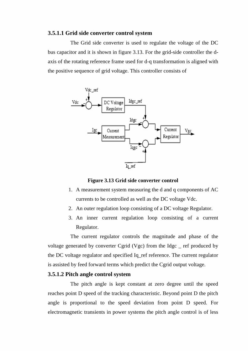
3.5.1.1 Grid side converter control system
The Grid side converter is used to regulate the voltage of the DC
bus capacitor and it is shown in figure 3.13. For the grid-side controller the d-
axis of the rotating reference frame used for d-q transformation is aligned with
the positive sequence of grid voltage. This controller consists of
Figure 3.13 Grid side converter control
1. A measurement system measuring the d and q components of AC
currents to be controlled as well as the DC voltage Vdc.
2. An outer regulation loop consisting of a DC voltage Regulator.
3. An inner current regulation loop consisting of a current
Regulator.
The current regulator controls the magnitude and phase of the
voltage generated by converter Cgrid (Vgc) from the Idgc _ ref produced by
the DC voltage regulator and specified Iq_ref reference. The current regulator
is assisted by feed forward terms which predict the Cgrid output voltage.
3.5.1.2 Pitch angle control system
The pitch angle is kept constant at zero degree until the speed
reaches point D speed of the tracking characteristic. Beyond point D the pitch
angle is proportional to the speed deviation from point D speed. For
electromagnetic transients in power systems the pitch angle control is of less
interest. The wind speed should be selected such that the rotational speed is
less than the speed at point D.
3.6 POWER QUALITY
Power quality is a concept used to characteristics an essential set of
parameters that determine the impact of wind turbines on the voltage quality
of an electric power network. It applies in principle both to transmission and
distribution networks, but is far more essential for the medium voltage
networks. The relevant parameters are active and reactive power, including
maximum value, voltage fluctuations (flicker), number of switching
operations (and resulting voltage variations), harmonic currents and related
quantities.
3.7 IMPACTS
Impacts can be classified mainly into two types.
1. Local impacts
2. Systems impacts.
3.7.1 Local Impacts
Local impacts of wind power are impacts that occur in the
(electrical) vicinity of a wind turbine or wind farm and can be attributed to a
specific turbine or farm. Local impacts occur at each turbine are largely
independent of the overall wind power penetration level in the system as a
whole.
Local impacts are
1. Branch flows and node voltages.
2. Protection schemes, fault currents and switch gear ratings.
3. Harmonic distortion.
4. Flicker
3.7.1.1 Branch flows and node voltages
The way in which wind turbines locally affect the node voltages
depends on speed of the turbine used .The squirrel cage induction generator in
constant speed cannot affect node voltages by adopting the reactive power
exchange with the grid. For this additional equipment for generating
controllable amounts of reactive power would be necessary. On the other hand
variable speed turbines have, at least theoretically, the capability of varying
reactive power to affect their terminal voltage, but this depends on the rating
of the controllers of the power electronic converter.
3.7.1.2 Protection schemes, faults currents and switch gear ratings
Protection schemes and switchgear ratings must be checked when
connecting new generation capacity. These are independent of the prime
mover of the generator. The contribution of wind turbines to the fault currents
also differs between the three main wind turbine types. Constant speed
turbines are based on a directly grid coupled squirrel cage induction generator.
They therefore contribute to the fault current and relay on conventional
protection schemes. Turbines based on the doubly fed induction generator
also contribute to the fault current.
However, the control system of power electronic converter that
controls the rotor current measures faults currents very quickly. Due to the
sensitivity of power electronics to over currents, this wind turbine type is
currently quickly disconnected when a fault is detected. Wind turbines with a
direct drive generator hardly contribute to the fault current because the power
electronic converter through which the generator is connected to the grid is
not capable of supplying a fault current.
3.7.1.3 Harmonic distortion
It is mainly an issue in the case of variable speed turbines because
this contains power electronic devices, which are sources of harmonics.
Harmonics cause over heating of transformer and generators. This also cause
increase in currents through shunt capacitors and thus leading to the failure
of such capacitors.
A practical solution would be to provide shunt filters at the PCC of
non-linear loads and reduce the harmonic currents flowing all over the
network. This would result in lower voltage distortion. In the case of modern
power electronic converters with their high switching frequencies and
advanced algorithms and filtering techniques, harmonic distortion should not

be a principal problem. Well-designed, directly coupled synchronous and
asynchronous generators hardly emit harmonics.
3.7.1.4 Flicker
Flicker is a specific property of wind turbines. Wind is a quite
rapidly fluctuating prime mover. In constant speed turbines, prime mover
fluctuations are directly translated into output power fluctuation, because
there is no buffer between mechanical input and electrical output. Depending
on the strength of the grid connection, the resulting power fluctuations can
result in grid voltage fluctuations, which can cause unwanted and annoying
fluctuations in bulb brightness. This problem is referred to as flicker.
In general, no flicker problem occurs with variable speed turbines,
because in these turbines wind speed fluctuations are not directly translated
into output power fluctuations. The rotor inertia acts as an energy buffer.
3.7.1.5 Harmonic reduction
The proliferation of power electronics devices have resulted in
distortion of the steady state ac current and voltage waveforms. Equipments
realized through these devices pose as non-linear loads and draw reactive and
harmonic currents in addition to the active load current. The reactive and
harmonic currents lead to poor power factor, low efficiency, electromagnetic
interference with neighboring electronic appliances and overheating of
transformers. In most of the distribution systems, power is distributed through
three-phase four-wire network. The non-linear loads, present in the system,
result in excessive neutral current due to triple harmonics, which are
potentially damaging to both neutral conductor and distribution transformer.
Hence the above problems are prevented effectively mainly the
harmonics is reduced by the control scheme implemented.
3.7.2 System Impacts
System-impacts are the impacts that affect the behavior of the
system as whole. They are an inherent consequence from the application of
wind power but cannot be attributed to individual turbines or farms. They are

strongly related to the wind power penetration level in the system that is the
contribution of wind power to actual load.
System impacts are
1. Power system dynamics and stability
2. Reactive power and voltage control.
3. Frequency control and load dispatching of conventional unit.
3.7.2.1 Power system dynamics and stability
In order to investigate the impact of wind power on power system
dynamics and stability, adequate wind turbine models are essential. Squirrel
cage induction generator used with constant speed turbine can lead to voltage
and rotor speed instability. During a fault, they accelerate due to the
unbalance between mechanical power extracted from the wind and electrical
power supplied to grid.
When the voltage restores, they consume much reactive power,
impeding voltage restoration. When the voltage returns to normal value
quickly, the wind turbines continue to accelerate and to consume large
amounts of reactive power. This eventually leads to voltage and rotor speed
instability. With variable speed turbines, the sensitivity of the power
electronics to over currents caused by voltage drops can have serious
consequences for the stability of power systems.
To prevent this, some grid companies and transmission system
operators prescribe that wind turbines must able to withstand voltage drops of
certain magnitudes and duration, in order to prevent the disconnection of a
large amount of wind power during fault .In order to meet this requirements,
manufactures of variables speed wind turbines are implementing solutions to
reduce the sensitivity of variable speed wind turbines with grid voltage drops.
3.7.2.2 Reactive power and voltage control
The impact of wind power on reactive power generation and
voltage control originates first from the fact that not all wind turbines are
capable of varying their reactive power output.
First of all wind power cannot be very flexibly located when
compared to conventional generation. Secondly wind turbines are relatively
weakly coupled to the system because their output voltage is rather low and
are often erected at the distinct locations. This further reduces their
contribution towards voltage control. When wind turbines at remote locations
on a large scale replace the output of conventional synchronous generator, the
voltage control aspect must therefore be taken into account explicitly.
3.7.2.3 Frequency control and load dispatching of conventional units
The impact of wind power on frequency control and load
dispatching is caused by the fact that the prime mover of wind power is
uncontrollable. Therefore, wind power hardly ever contributes to primary
frequency regulation. Further, the variability of the wind on the longer term
tends to complicate the load dispatching with the conventional units that
remain in the system, as the demand curve to be matched by these units is far
less smooth than would be the case without wind power. This heavily affects
the dispatch of power from the conventional generators.
Note that the aggregate short term output power fluctuations of a
large number of wind turbines are very smooth and are generally not
considered as problem. The impact of wind power on frequency control and
load dispatching becomes more severe. The higher the wind power
penetration level is. The higher the wind power penetration, the larger the
impact of wind power on the demand curve faced by remaining conventional
units. It is however, impossible to quantify the wind power penetration level
at which system wide effects start to occur because of the differences in
demand curve and network topology between various power systems.
The above impacts are solved to some extent. But there is no
proper solution to the problems caused by high-speed winds. During high-
speed winds, the turbine speed exceeds its limit. This will cause
1. Very high fluctuations in voltage
2. Very high fluctuations in frequencies
3. It may damage the rotor

These problems to some extent can be solved by
1. By using some governing mechanism to operate gear mechanism to
control the speed of the rotor of the wind turbine.
2. By using computer techniques we may control the speed of the
turbine or disconnecting the turbine from generator during high-
speed winds.
3. By connecting parachutes to the rotor for blades emergency
stopping of the rotor.
3.8 REQUIREMENTS OF GRID CONNECTION
Interconnection of the doubly fed induction generator to the grid is
shown in figure 3.14. If wind farms would be installed solely to maximize
energy output, they would have major limitations in terms of
1. Power Control and Frequency Range.
2. Power Factor and Voltage Control
3. Transient Fault Behavior, Voltage Operating Range
Figure 3.14 Interconnection of the doubly fed induction generator to the grid
These are the three main issues that new grid codes must address
for wind farm connection. The most worrying problem that wind farms must
face is a voltage dip in the grid. The effects of transient faults may propagate
over very large geographical areas and the disconnection of wind farms under
fault conditions could pose a serious threat to network security and security of
supply because a great amount of wind power could be disconnected
simultaneously.
3.8.1 Reactive Power Control
Voltage and current are typically measured 128 times per
alternating current cycle, (i.e. 50 x 128 times per second or 60 x 128 times per
second, depending on the electrical grid frequency). On this basis, a so called
DSP processor calculates the stability of the grid frequency and the active 25
and reactive power of the turbine. (The reactive power component is basically
a question of whether the voltage and the current are in phase or not). The
term "power quality" refers to the voltage stability, frequency stability, and
the absence of various forms of electrical noise (e.g. flicker or harmonic
distortion) on the electrical grid. More broadly speaking, power companies
(and their customers) prefer an alternating current with a nice sinusoidal
shape.
3.8.2 Power Control and Frequency Range
It must be possible to limit the active power output from every
operating point as a percentage of the nominal power. For power reduction a
ramp rate of at least 10% of nominal power per minute must be possible. If
power is ramped down, this must not imply disconnection of single turbines
from the grid. In the wake of loss of grid voltage, power has to be ramped up
with a gradient of not more than 10% of nominal power per minute. This
ramp can be realized in steps (reconnection of single wind turbines), if the
step size does not exceed 10% of nominal power per minute. The frequency
range wind turbines have to tolerate is about 47.5-51.5 Hz. According to the
requirements of German transmission grid operators, large wind farms have to
be treated in the future like conventional power plants.

3.8.3 Power Factor and Voltage Control
It has to be possible to operate wind farms with nominal power of
less than 100 MW with power factor between 0.95 lagging and 0.95 leading.
The required power factor values are always applied at the grid connection
point. Wind farms rated 100 MW or more have to be able to operate at power
factor between 0.925 lagging and 0.95 leading. The power factor range is
however limited depending on the grid voltage to avoid leading power.
3.8.4 Generating Alternating Current (AC) at Variable Frequency
Most wind turbines run at almost constant speed with direct grid
connection. With indirect grid connection, however, the wind turbine
generator runs in its own, separate mini AC-grid, as illustrated in the graphic.
This grid is controlled electronically (using an inverter), so that the frequency
of the alternating current in the stator of the generator may be varied. In this
way it is possible to run the turbine at variable rotational speed. Thus the
turbine will generate alternating current at exactly the variable frequency
applied to the stator. The generator may be either a synchronous generator or
an asynchronous generator, and the turbine may have a gearbox, as in the
image above, or run without a gearbox if the generator has many poles.
3.8.5 Conversion to Direct Current (DC)
AC current with a variable frequency cannot be handled by the
public electrical grid. We therefore start by rectifying it. The conversion from
variable frequency AC to DC can be done using thyristors or large power
transistors.
3.8.6 Conversion to Fixed Frequency AC
The (fluctuating) direct current is converted in to an alternating
current (using an inverter) with exactly the same frequency as the public
electrical grid. This conversion to AC in the inverter can also be done using
either thyristors or transistors.
3.8.7 Filtering the AC
The rectangular shaped waves can be smoothed out, however, using
appropriate inductances and capacitors, in a so-called AC filter mechanism.

The somewhat jagged appearance of the voltage does not disappear
completely.
3.8.8 Advantages of Indirect Grid Connection
The advantage of indirect grid connection is that it is possible to run
the wind turbine at variable speed. The primary advantage is that gusts of
wind can be allowed to make the rotor turn faster, thus storing part of the
excess energy as rotational energy until the gust is over. Obviously, this
requires an intelligent control strategy, since we have to be able to
differentiate between gusts and higher wind speed in general. Thus it is
possible to reduce the peak torque (reducing wear on the gearbox and
generator), and we may also reduce the fatigue loads on the tower and rotor
blades. The secondary advantage is that with power electronics one may
control reactive power (i.e. the phase shifting of current relative to voltage in
the AC grid), so as to improve the power quality in the electrical grid. This
may be useful, particularly if a turbine is running on a weak electrical grid.
Theoretically, variable speed may also give a slight advantage in terms of
annual production, since it is possible to run the machine at an optimal
rotational speed, depending on the wind speed. From an economic point of
view that advantage is so small, however, that it is hardly worth mentioning.
3.8.9 Disadvantages of Indirect Grid Connection
The basic disadvantage of indirect grid connection is cost. As we
just learned, the turbine will need a rectifier and two inverters, one to control
the stator current, and another to generate the output current. Presently, it
seems that the cost of power electronics exceeds the gains to be made in
building lighter turbines, but that may change as the cost of power electronics
decreases. Looking at operating statistics from wind turbines using power
electronics, it also seems that availability rates for these machines tend to be
somewhat lower than conventional machines, due to failures in the power
electronics. Other disadvantages are the energy lost in the AC-DC-AC
conversion process, and the fact that power electronics may introduce
harmonic distortion of the alternating current in the electrical grid, thus
reducing power quality. Although the size and direction of the wind is
stochastic and the output power of the wind turbine varies with the starting
and ceasing of the system, the induction generator has many merits, such as
low cost, high credibility and easy servicing. The modes of induction
generator connected to grid are adopted in large wind farms. There’re two
types of wind turbine connected to grid. One is the direct grid-connection
mode; the other is connected to grid though a power electronics
Doubly fed induction generator with cascaded converter slip power
recovery;
Doubly fed induction generator with cycloconverter slip power
recovery
Synchronous generator with line-commutated and load commutated
thyristor Converters
In addition to the above schemes, squirrel cage generators with
shunt passive or active VAR (volt ampere reactive) generators have been
proposed which generate constant voltage constant frequency power through a
diode rectifier and line-commutated thyristor inverter. Recently, a variable
reluctance machine and doubly stator-fed induction machine have also been
proposed in wind generation systems. Very recently, a double sided pulse
width modulated (PWM) converter system has been proposed to overcome
some of the above problems. This describes a VSWT system with a squirrel
cage induction generator and a double-sided PWM converter where Neuro
fuzzy logic control has been used extensively to maximize the power output
and enhance system performance.
3.9 EXISTING SYSTEM
This paper proposes a hybrid ac/dc micro grid to reduce the processes
of multiple dc–ac–dc or ac–dc–ac conversions in an individual ac or dc grid.
The hybrid grid consists of both ac and dc networks connected together by
multi-bidirectional converters. AC sources and loads are connected to the ac
network whereas dc sources and loads are tied to the dc network. Energy
storage systems can be connected to dc or ac links. The proposed hybrid grid
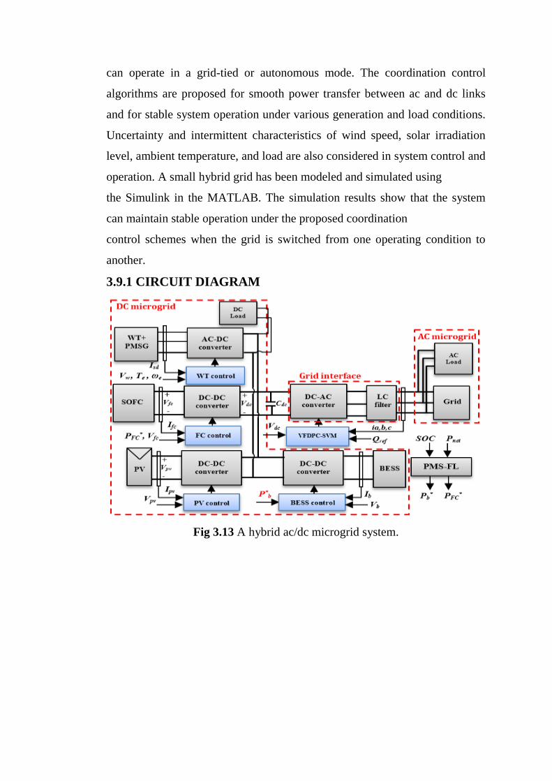
can operate in a grid-tied or autonomous mode. The coordination control
algorithms are proposed for smooth power transfer between ac and dc links
and for stable system operation under various generation and load conditions.
Uncertainty and intermittent characteristics of wind speed, solar irradiation
level, ambient temperature, and load are also considered in system control and
operation. A small hybrid grid has been modeled and simulated using
the Simulink in the MATLAB. The simulation results show that the system
can maintain stable operation under the proposed coordination
control schemes when the grid is switched from one operating condition to
another.
3.9.1 CIRCUIT DIAGRAM
Fig 3.13 A hybrid ac/dc microgrid system.
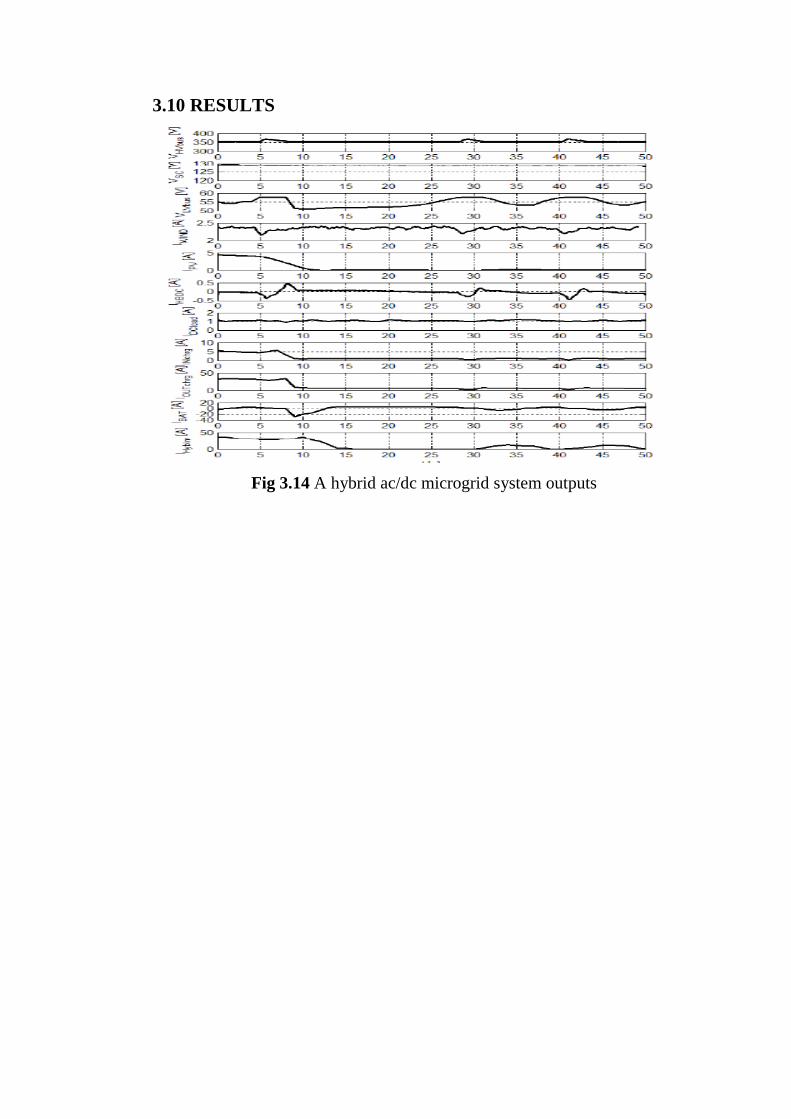
3.10 RESULTS
Fig 3.14 A hybrid ac/dc microgrid system outputs
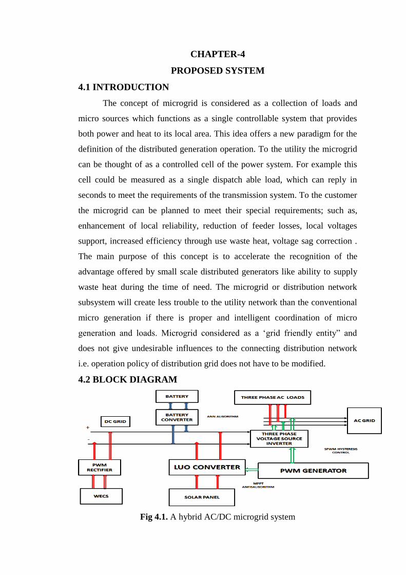
CHAPTER-4
PROPOSED SYSTEM
4.1 INTRODUCTION
The concept of microgrid is considered as a collection of loads and
micro sources which functions as a single controllable system that provides
both power and heat to its local area. This idea offers a new paradigm for the
definition of the distributed generation operation. To the utility the microgrid
can be thought of as a controlled cell of the power system. For example this
cell could be measured as a single dispatch able load, which can reply in
seconds to meet the requirements of the transmission system. To the customer
the microgrid can be planned to meet their special requirements; such as,
enhancement of local reliability, reduction of feeder losses, local voltages
support, increased efficiency through use waste heat, voltage sag correction .
The main purpose of this concept is to accelerate the recognition of the
advantage offered by small scale distributed generators like ability to supply
waste heat during the time of need. The microgrid or distribution network
subsystem will create less trouble to the utility network than the conventional
micro generation if there is proper and intelligent coordination of micro
generation and loads. Microgrid considered as a ‘grid friendly entity” and
does not give undesirable influences to the connecting distribution network
i.e. operation policy of distribution grid does not have to be modified.
4.2 BLOCK DIAGRAM
Fig 4.1. A hybrid AC/DC microgrid system

4.3 CIRCUIT DIAGRAM
Fig 4.2. A hybrid AC/DC microgrid system Circuit diagram
The configuration of the hybrid system is shown in Figure 4.1 where
various AC and DC sources and loads are connected to the corresponding AC
and DC networks. The AC and DC links are linked together through two
transformers and two four quadrant operating three phase converters. The AC
bus of the hybrid grid is tied to the utility grid. Figure 4.2 describes the hybrid
system configuration which consists of AC and DC grid. The AC and DC
grids have their corresponding sources, loads and energy storage elements,
and are interconnected by a three phase converter. The AC bus is connected to
the utility grid through a transformer and circuit breaker. In the proposed
system, PV arrays are connected to the DC bus through boost converter to
simulate DC sources. A PMSG wind generation system is connected to AC
bus to simulate AC sources. A battery with bidirectional DC/DC converter is
connected to DC bus as energy storage. A variable DC and AC load are
connected to their DC and AC buses to simulate various loads. PV modules
are connected in series and parallel. As solar radiation level and ambient
temperature changes the output power of the solar panel alters. A capacitor C
is added to the PV terminal in order to suppress high frequency ripples of the
PV output voltage. The bidirectional DC/DC converter is designed to
maintain the stable DC bus voltage through charging or discharging the
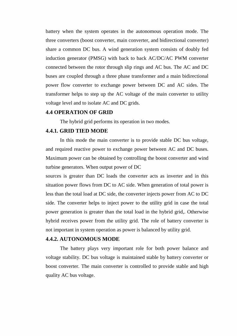
battery when the system operates in the autonomous operation mode. The
three converters (boost converter, main converter, and bidirectional converter)
share a common DC bus. A wind generation system consists of doubly fed
induction generator (PMSG) with back to back AC/DC/AC PWM converter
connected between the rotor through slip rings and AC bus. The AC and DC
buses are coupled through a three phase transformer and a main bidirectional
power flow converter to exchange power between DC and AC sides. The
transformer helps to step up the AC voltage of the main converter to utility
voltage level and to isolate AC and DC grids.
4.4 OPERATION OF GRID
The hybrid grid performs its operation in two modes.
4.4.1. GRID TIED MODE
In this mode the main converter is to provide stable DC bus voltage,
and required reactive power to exchange power between AC and DC buses.
Maximum power can be obtained by controlling the boost converter and wind
turbine generators. When output power of DC
sources is greater than DC loads the converter acts as inverter and in this
situation power flows from DC to AC side. When generation of total power is
less than the total load at DC side, the converter injects power from AC to DC
side. The converter helps to inject power to the utility grid in case the total
power generation is greater than the total load in the hybrid grid,. Otherwise
hybrid receives power from the utility grid. The role of battery converter is
not important in system operation as power is balanced by utility grid.
4.4.2. AUTONOMOUS MODE
The battery plays very important role for both power balance and
voltage stability. DC bus voltage is maintained stable by battery converter or
boost converter. The main converter is controlled to provide stable and high
quality AC bus voltage.
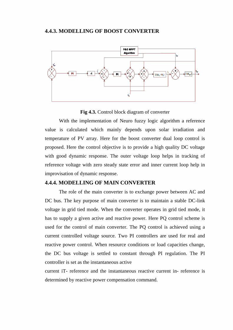
4.4.3. MODELLING OF BOOST CONVERTER
Fig 4.3. Control block diagram of converter
With the implementation of Neuro fuzzy logic algorithm a reference
value is calculated which mainly depends upon solar irradiation and
temperature of PV array. Here for the boost converter dual loop control is
proposed. Here the control objective is to provide a high quality DC voltage
with good dynamic response. The outer voltage loop helps in tracking of
reference voltage with zero steady state error and inner current loop help in
improvisation of dynamic response.
4.4.4. MODELLING OF MAIN CONVERTER
The role of the main converter is to exchange power between AC and
DC bus. The key purpose of main converter is to maintain a stable DC-link
voltage in grid tied mode. When the converter operates in grid tied mode, it
has to supply a given active and reactive power. Here PQ control scheme is
used for the control of main converter. The PQ control is achieved using a
current controlled voltage source. Two PI controllers are used for real and
reactive power control. When resource conditions or load capacities change,
the DC bus voltage is settled to constant through PI regulation. The PI
controller is set as the instantaneous active
current iT- reference and the instantaneous reactive current in- reference is
determined by reactive power compensation command.

Fig 4.4. Control block diagram of main converter
In case of sudden DC load drop, there is power surplus at DC side and
the main converter is controlled to transfer power from DC to AC side. The
active power absorbed by the capacitor CT leads to rising of DC-link voltage
VT. The negative error caused by the increase of VT produces a higher active
current reference iT through PI control. A higher positive reference iT will
force active current reference iT- to increase through the inner current control
loop. Therefore the power surplus of the DC grid can be transferred to the AC
side. Also a sudden increase of DC load causes the power shortage and VT
drop at the DC grid. The main converter is controlled to supply power from
the AC to DC side. The positive voltage error caused by VT drop makes the
magnitude of iT- increase through the PI control. Since iT- and iT are both
negative, the magnitude of iT- is increased through the inner current control
loop. Hence power is transferred from AC grid to the DC side.
4.5 INTRODUCTION TO NFLC
Neuro fuzzy logic has rapidly become one of the most successful
of today’s technology for developing sophisticated control system. With it
aid complex requirement so may be implemented in amazingly simple,
easily minted and inexpensive controllers. The past few years have
witnessed a rapid growth in number and variety of application of Neuro
fuzzy logic. The application range from consumer products such as

cameras ,camcorder ,washing machines and microwave ovens to industrial
process control ,medical instrumentation ,and decision- support system
.many decision-making and problem solving tasks are too complex to be
understand quantitatively however ,people succeed by using knowledge that
is imprecise rather than precise .
Neuro fuzzy logic is all about the relative importance of precision.
Neuro fuzzy logic has two different meanings .in a narrow senses, Neuro
fuzzy logic is a logical system which is an extension of multi valued logic
.but in wider sense Neuro fuzzy logic is synonymous with the theory of
Neuro fuzzy sets . Neuro fuzzy set theory is originally introduced by
Lotfi Zadeh in the 1960, resembles approximate reasoning in it use of
approximate information and uncertainty to generate decisions.
Several studies show, both in simulations and experimental results,
that Neuro fuzzy Logic control yields superior results with respect to those
obtained by conventional control algorithms thus, in industrial electronics
the FLC control has become an attractive solution in controlling the
electrical motor drives with large parameter variations like machine tools
and robots. However, the FL Controllers design and tuning process is often
complex because several quantities, such as membership functions, control
rules, input and output gains, etc must be adjusted. The design process of a
FLC can be simplified if some of the mentioned quantities are obtained
from the parameters of a given Proportional-Integral controller (PIC) for the
same application.
4.5.1 MOTIVATIONS FOR CHOOSING NEURO FUZZY LOGIC
CONTROLLER
Neuro fuzzy logic controller can model nonlinear system
The design of conventional control system essential is normally
based on the mathematical model of plant .if an accurate mathematical
model is available with known parameters it can be analyzed., for
example by bode plots or nyquist plot , and controller can be designed
for specific performances .such procedure is time consuming.
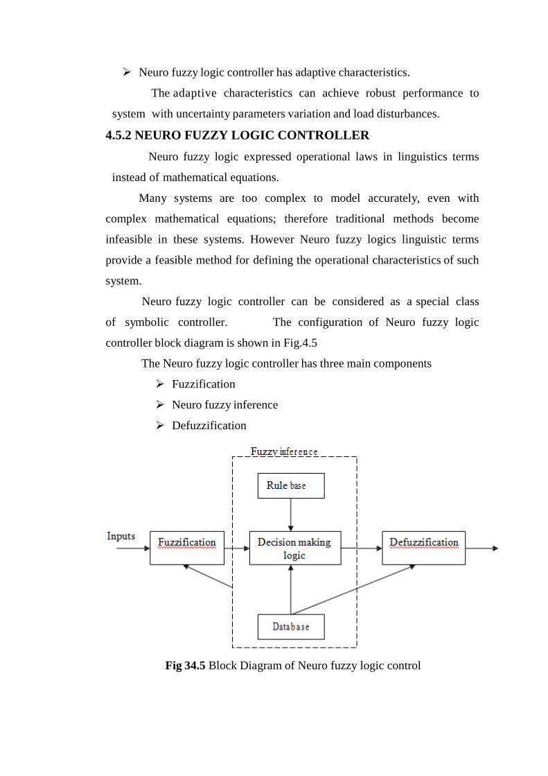
Neuro fuzzy logic controller has adaptive characteristics.
The adaptive characteristics can achieve robust performance to
system with uncertainty parameters variation and load disturbances.
4.5.2 NEURO FUZZY LOGIC CONTROLLER
Neuro fuzzy logic expressed operational laws in linguistics terms
instead of mathematical equations.
Many systems are too complex to model accurately, even with
complex mathematical equations; therefore traditional methods become
infeasible in these systems. However Neuro fuzzy logics linguistic terms
provide a feasible method for defining the operational characteristics of such
system.
Neuro fuzzy logic controller can be considered as a special class
of symbolic controller. The configuration of Neuro fuzzy logic
controller block diagram is shown in Fig.4.5
The Neuro fuzzy logic controller has three main components
Fuzzification
Neuro fuzzy inference
Defuzzification
Fig 34.5 Block Diagram of Neuro fuzzy logic control
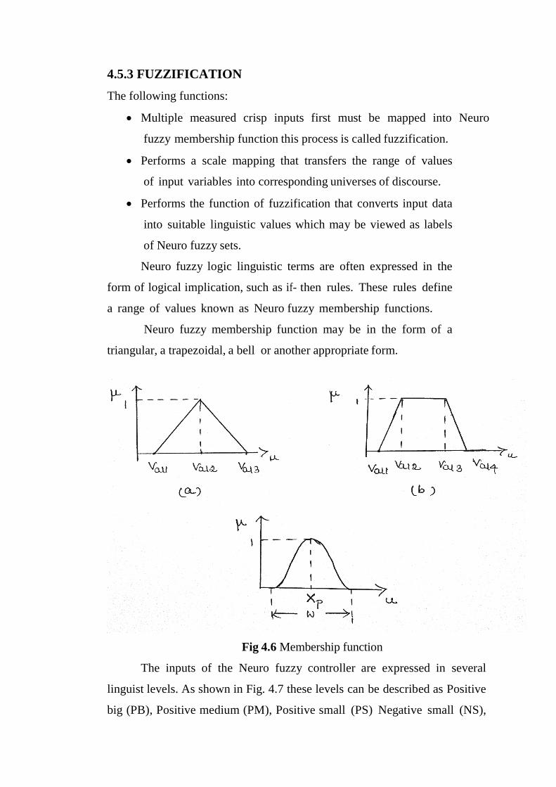
4.5.3 FUZZIFICATION
The following functions:
Multiple measured crisp inputs first must be mapped into Neuro
fuzzy membership function this process is called fuzzification.
Performs a scale mapping that transfers the range of values
of input variables into corresponding universes of discourse.
Performs the function of fuzzification that converts input data
into suitable linguistic values which may be viewed as labels
of Neuro fuzzy sets.
Neuro fuzzy logic linguistic terms are often expressed in the
form of logical implication, such as if- then rules. These rules define
a range of values known as Neuro fuzzy membership functions.
Neuro fuzzy membership function may be in the form of a
triangular, a trapezoidal, a bell or another appropriate form.
Fig 4.6 Membership function
The inputs of the Neuro fuzzy controller are expressed in several
linguist levels. As shown in Fig. 4.7 these levels can be described as Positive
big (PB), Positive medium (PM), Positive small (PS) Negative small (NS),
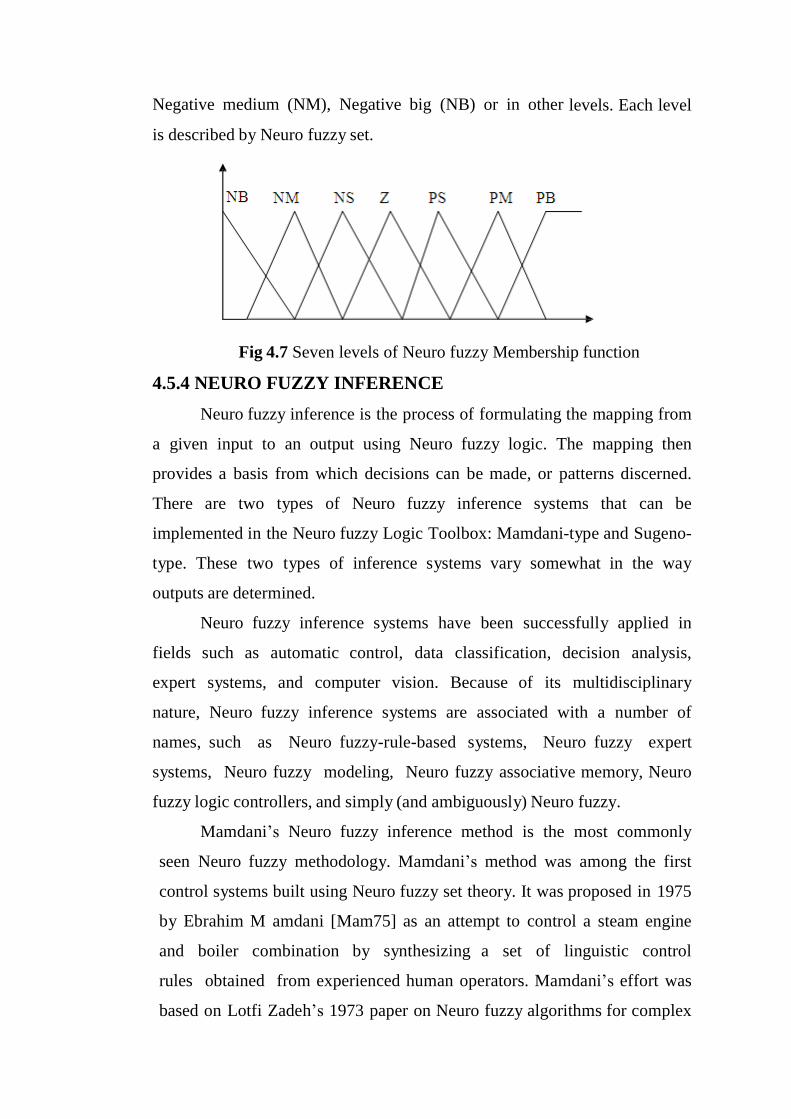
Negative medium (NM), Negative big (NB) or in other levels. Each level
is described by Neuro fuzzy set.
Fig 4.7 Seven levels of Neuro fuzzy Membership function
4.5.4 NEURO FUZZY INFERENCE
Neuro fuzzy inference is the process of formulating the mapping from
a given input to an output using Neuro fuzzy logic. The mapping then
provides a basis from which decisions can be made, or patterns discerned.
There are two types of Neuro fuzzy inference systems that can be
implemented in the Neuro fuzzy Logic Toolbox: Mamdani-type and Sugeno-
type. These two types of inference systems vary somewhat in the way
outputs are determined.
Neuro fuzzy inference systems have been successfully applied in
fields such as automatic control, data classification, decision analysis,
expert systems, and computer vision. Because of its multidisciplinary
nature, Neuro fuzzy inference systems are associated with a number of
names, such as Neuro fuzzy-rule-based systems, Neuro fuzzy expert
systems, Neuro fuzzy modeling, Neuro fuzzy associative memory, Neuro
fuzzy logic controllers, and simply (and ambiguously) Neuro fuzzy.
Mamdani’s Neuro fuzzy inference method is the most commonly
seen Neuro fuzzy methodology. Mamdani’s method was among the first
control systems built using Neuro fuzzy set theory. It was proposed in 1975
by Ebrahim M amdani [Mam75] as an attempt to control a steam engine
and boiler combination by synthesizing a set of linguistic control
rules obtained from experienced human operators. Mamdani’s effort was
based on Lotfi Zadeh’s 1973 paper on Neuro fuzzy algorithms for complex

systems and decision processes [Zad73].
The second phase of the Neuro fuzzy logic controller is its
Neuro fuzzy inference where the knowledge base and decision making
logic reside .The rule base and data base from the knowledge base. The
data base contains the description of the input and output variables. The
decision making logic evaluates the control rules .the control-rule base can
be developed to relate the output action of the controller to the obtained
inputs.
4.5.5 DEFUZZIFICATION
The output of the inference mechanism is Neuro fuzzy output variables.
The Neuro fuzzy logic controller must convert its internal Neuro fuzzy
output variables into crisp values so that the actual system can use these
variables. This conversion is called Defuzzification. One may perform this
operation in several ways. The commonly used control Defuzzification
strategies are
(a).The max criterion method (MAX)
The max criterion produces the point at which the membership
function of Neuro fuzzy control action reaches a maximum value.
(b)The height method
The centroid of each membership function for each rule is first
evaluated. The final output U 0 is then calculated as the average of the
individual centroids, weighted by their heights as follows:
(c) The centroid method or center of area method (COA)
The widely used centroid strategy generates the center of gravity of area
bounded by the Membership function are
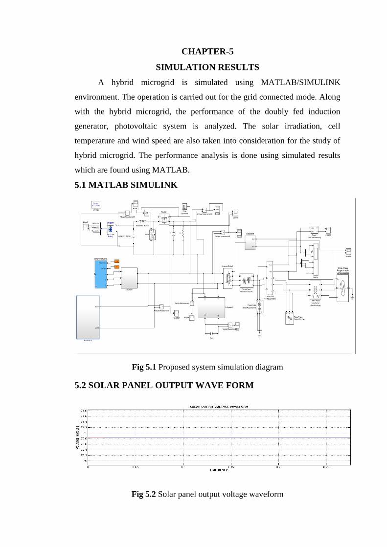
CHAPTER-5
SIMULATION RESULTS
A hybrid microgrid is simulated using MATLAB/SIMULINK
environment. The operation is carried out for the grid connected mode. Along
with the hybrid microgrid, the performance of the doubly fed induction
generator, photovoltaic system is analyzed. The solar irradiation, cell
temperature and wind speed are also taken into consideration for the study of
hybrid microgrid. The performance analysis is done using simulated results
which are found using MATLAB.
5.1 MATLAB SIMULINK
Fig 5.1 Proposed system simulation diagram
5.2 SOLAR PANEL OUTPUT WAVE FORM
Fig 5.2 Solar panel output voltage waveform
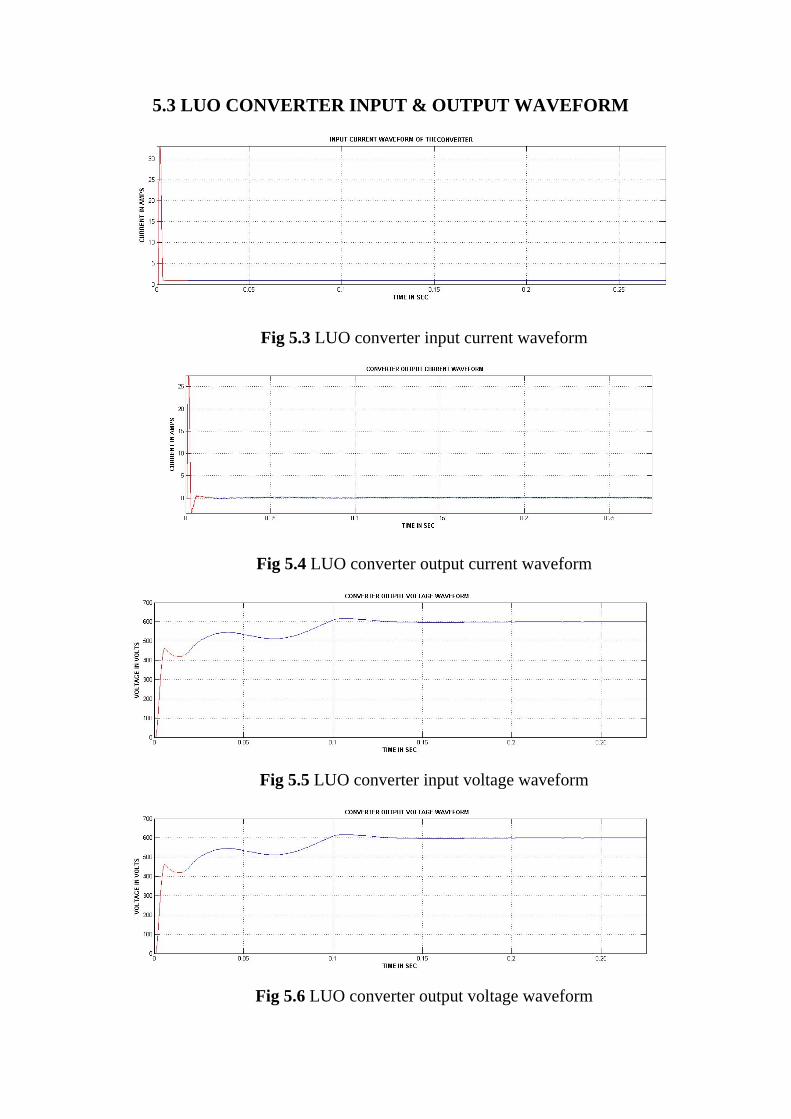
5.3 LUO CONVERTER INPUT & OUTPUT WAVEFORM
Fig 5.3 LUO converter input current waveform
Fig 5.4 LUO converter output current waveform
Fig 5.5 LUO converter input voltage waveform
Fig 5.6 LUO converter output voltage waveform
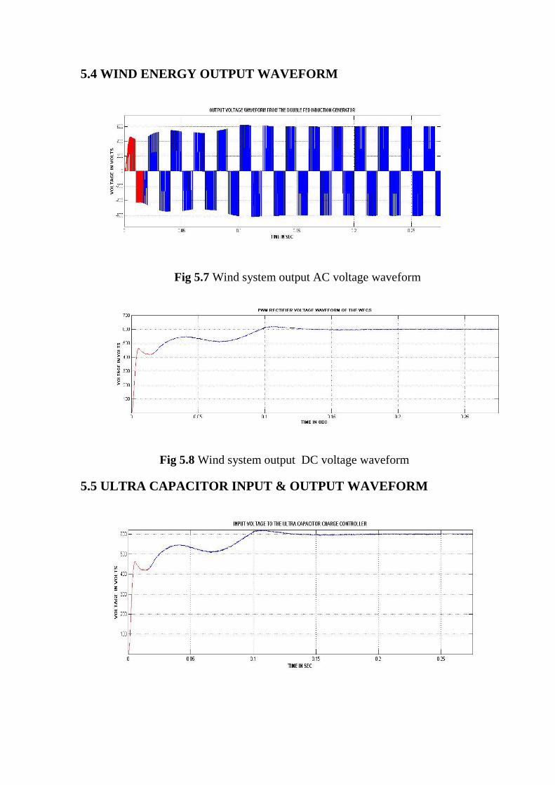
5.4 WIND ENERGY OUTPUT WAVEFORM
Fig 5.7 Wind system output AC voltage waveform
Fig 5.8 Wind system output DC voltage waveform
5.5 ULTRA CAPACITOR INPUT & OUTPUT WAVEFORM
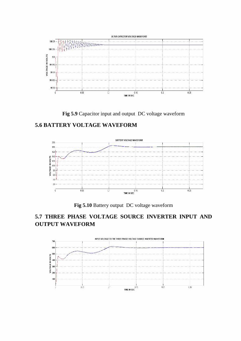
Fig 5.9 Capacitor input and output DC voltage waveform
5.6 BATTERY VOLTAGE WAVEFORM
Fig 5.10 Battery output DC voltage waveform
5.7 THREE PHASE VOLTAGE SOURCE INVERTER INPUT AND
OUTPUT WAVEFORM
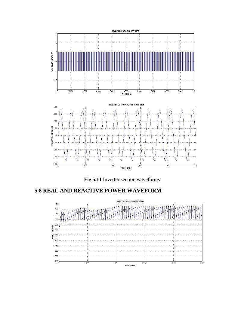
Fig 5.11 Inverter section waveforms
5.8 REAL AND REACTIVE POWER WAVEFORM
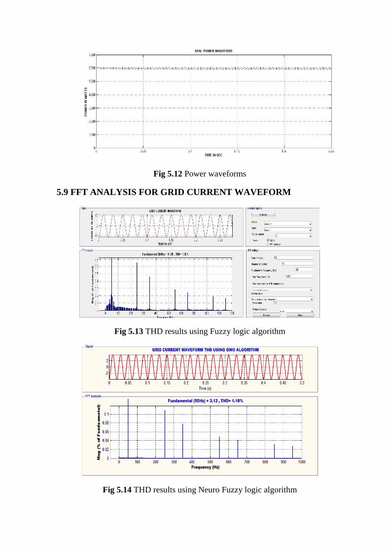
Fig 5.12 Power waveforms
5.9 FFT ANALYSIS FOR GRID CURRENT WAVEFORM
Fig 5.13 THD results using Fuzzy logic algorithm
Fig 5.14 THD results using Neuro Fuzzy logic algorithm

TABLE 5.1 COMPARISON BETWEEN EXISTING AND
PROPOSED WORK
SI NO PARAMETERS EXISTING LUO
CONVERTER
MODIFIED LUO
CONVERTER
1 THD 1.98 1.18
2 MPPT Efficiency 92% 96%
CHAPTER-6
CONCLUSION
6.1 CONCLUSION
The modelling of hybrid microgrid for power system configuration is
done in MATLAB/SIMULINK environment. The present work mainly
includes the grid tied mode of operation of hybrid grid. The models are
developed for all the converters to maintain stable
system under various loads and resource conditions and also the control
mechanism are studied. MPPT Neuro fuzzy algorithm is used to harness
maximum power from DC sources and to coordinate the power exchange
between DC and AC grid. Although the hybrid grid can diminish the
processes of DC/AC and AC/DC conversions in an individual AC or DC grid,
there are many practical problems for the implementation of the hybrid grid
based on the current AC dominated infrastructure. The efficiency of the total
system depends on the diminution of conversion losses and the increase for an
extra DC link. The hybrid grid can provide a reliable, high quality and more
efficient power to consumer. The hybrid grid may be feasible for small
isolated industrial plants with both PV systems and wind turbine generator as
the major power supply.

REFERENCES
[1] S. Bose, Y. Liu, K. Bahei-Eldin, J.de Bedout, and M. Adamiak, “Tie line
Controls in Microgrid Applications,” in iREP Symposium Bulk Power System
Dynamics and Control VII, Revitalizing Operational Reliability, pp. 1-9, Aug.
2007.
[2] R. H. Lasseter, “MicroGrids,” in Proc. IEEE-PES’02, pp. 305-308, 2002.
[3] Michael Angelo Pedrasa and Ted Spooner, “A Survey of Techniques Used
to Control Microgrid Generation and Storage during Island Operation,” in
AUPEC, 2006.
[4] F. D. Kanellos, A. I. Tsouchnikas, and N. D. Hatziargyriou, “Microgrid
Simulation during Grid-Connected and Islanded Mode of Operation,” in Int.
Conf. Power Systems Transients (IPST’05), June. 2005.
[5] Y. W. Li, D. M. Vilathgamuwa, and P. C. Loh, Design, analysis, and real-
time testing of a controller for multi bus microgrid system, IEEE Trans.
Power Electron., vol. 19, pp. 1195-1204, Sep. 2004.
[6] R. H. Lasseter and P. Paigi, “Microgrid: A conceptual solution,” in Proc.
IEEEPESC’ 04, pp. 4285-4290, 2004.
[7] F. Katiraei and M. R. Iravani, “Power Management Strategies for a
Microgrid with Multiple Distributed Generation Units,” IEEE trans. Power
System, vol. 21, no. 4, Nov. 2006.
[8] P. Piagi and R. H. Lasseter, “Autonomous control of microgrids,” in Proc.
IEEE-PES’06, 2006, IEEE, 2006.
[9] M. Barnes, J. Kondoh, H. Asano, and J. Oyarzabal, “Real-World
MicroGrids- an Overview,” in IEEE Int. Conf. Systems of Systems
Engineering, pp.1-8, 2007.
[10]Chi Jin, Poh Chiang Loh, Peng Wang, Yang Mi, and Frede Blaabjerg,
“Autonomous Operation of Hybrid AC-DC Microgrids,” in IEEE Int. Conf.
Sustainable Energy Technologies, pp. 1-7, 2010.
[11]Y. Zoka, H. Sasaki, N.Yomo, K. Kawahara, C. C. Liu, “An Interaction
Problem of Distributed Generators Installed in a MicroGrid,” in Proc. IEEE

Elect. Utility Deregulation, Restructuring and Power Technologies, pp. 795-
799, Apr. 2004.
[12]H. Nikkhajoei, R. H. Lasseter, “Microgrid Protection,” in IEEE Power
Engineering Society General Meeting, pp. 1-6, 2007.
[13]Zhenhua Jiang, and Xunwei Yu, “Hybrid DC- and AC-Linked
Microgrids: Towards Integration of Distributed Energy Resources,” in IEEE
Energy2030 Conf., pp.1-8, 2008.
[14]Bo Dong, Yongdong Li, ZhixueZheng, Lie Xu “Control Strategies of
Microgrid with Hybrid DC and AC Buses,” in Power Electronics and
Applications, EPE'11, 14thEuropean Conf., pp. 1-8, 2011.
[15]Dong Bo, Yongdong Li , and Zedong Zheng, “Energy Management of
Hybrid DC and AC Bus Linked Microgrid,” in IEEE Int. Symposium Power
Electronics for Distributed Generation System, pp. 713-716, 2010.
[16]Xiong Liu, Peng Wang, and Poh Chiang Loh, “A Hybrid AC/DC
Microgrid and Its Coordination Control,” IEEE Trans. Smart Grid, vol. 2, no.
2, pp. 278-286 June. 2011.
[17]Mesut E. Baran, and Nikhil R. Mahajan, “DC Distribution for Industrial
Systems: Opportunities and Challenges,” IEEE Trans. Industry Applications,
vol. 39, no. 6, pp. 1596-1601, Nov/Dec. 2003.
[18]Y. Ito, Z. Yang, and H. Akagi, “DC Microgrid Based Distribution Power
Generation System,” in Proc. IEEE Int. Power Electron. Motion Control
Conf., vol. 3, pp. 1740- 1745, Aug. 2004.
[19]A. Arulampalam, N. Mithulananthan, R.C. Bansal, and T.K. Saba,
“Microgrid Control of PV -Wind-Diesel Hybrid System with Islanded and
Grid Connected Operations,” in Proc. IEEE Int. Conf. Sustainable Energy
Technologies, pp. 1-5, 2010.
[20]Poh Chiang Loh, Ding Li, and FredeBlaabjerg, “Autonomous Control of
Interlinking Converters in Hybrid AC-DC Microgrid with Energy Storages,”
in IEEE Energy Conversion Congress and Exposition (ECCE), pp. 652-658,
2011.


![[OOT] All-Commons Sealed Decklists](https://img.pdfslide.us/doc/110x75/55cf8f22550346703b994342/oot-all-commons-sealed-decklists.jpg)