Embed Size (px)
DESCRIPTION
Generic Simulator
Citation preview

OPERATING MANUAL
670 MW Coal Fired Power Plant Training Simulator
Steag Power Plant Learning Centre Steag Energy Services India Pvt. Ltd.
A-30, Sector -16, Noida, (U.P.) - 201301


GENERIC TPP SIMULATOR STARTUP PROCEDURE
INITIAL CONDITION
This exercise begins with the unit ordered to startup following an extended unit outage. The student performs preliminary checks and lineups; if necessary, fills the hotwell, deaerator, and boiler; starts the boiler; warms, rolls and synchronizes the turbine, and increases load.
The exercise is normally initialized at a condition representing deaerator, hotwell and boiler drained and no power to the unit buses.
• LP01A Cold SU: Vessels Empty / No Plant Power However, if desired, the simulator can be initialized with vessels filled to their normal operating levels and /or unit buses energized.
• LP01B Cold SU: Vessels Empty / Plant Power • LP01C Cold SU: Vessels Filled / No Plant Power • LP01D Cold SU: Vessels Filled / Plant Power The exercise is complete when the unit is stable in Coordinated Control Mode (the Boiler Master in auto and the Turbine Master in auto) at a load of ~300 GMW with boiler firing on coal and fuel oil shutdown.
STARTUP PROCEDURE SUMMARY
Following are the major steps involved in this exercise: 1. Line up the plant electrical system and provide power through the Startup Transformer to all switchgear, load centers
and motor control centers required for a startup to full load. 2. Place the Compressed Air System in service and line up the Instrument Air and Compressed Air Systems. 3. Line up and place in service the Closed Cooling Water system with one closed cooling water pump in service and
establish closed cooling water flow through various equipment coolers. 4. Line up and place the Vacuum Priming System and Circulating Water System in service with three circulating water
pumps in operation and establish flow through the main condenser and to the closed cooling water heat exchangers. 5. Line up the Condensate Storage System and fill the Condenser Hotwell to 65% (±5%). 6. Line up and place the Condensate System in service and fill the Deaerator:
- Place Condensate Pump A in operation and establish condensate recirculation flow through the GSC back to the condenser
- Place Condensate Pumps B and C in Standby - Fill the Deaerator to 65% (±5%) and begin Condensate circulation from Condenser to Deaerator and back - Line up and start ammonia injection to the Condensate Water at the Drain Coolers Inlet - Maintain Condensate circulation and ammonia injection until the Condensate water quality is satisfied (~9.3 pH)
7. Lineup the Feedwater System. Line up valving to fill the boiler through the Boiler Fill Valve and fill the boiler until the drum level is 200mm (±50mm).
8. Line up and fill the Seawater Scrubber Absorbers and FGD Emergency Cooling Water Tank. 9. Line up and place in operation the Main Turbine Lube Oil and EHC Systems. 10. Line up and place in service the lube oil systems for BFPT A and BFPT B. Place both BFPT's on turning gear. 11. Place the Main Turbine Turning Gear system in service. 12. Lineup and place the Stator Cooling Water system in service. 13. Lineup and place the Fuel Oil System in service with one Fuel Oil Pump running and the other two in auto. 14. Fill the boiler and lineup and start the Boiler Circulating Water Pumps with two pumps in operation. 15. Lineup and place the Bottom Ash Handling system and Bottom Ash Seal Water System in service. Lineup and place
the Combustion Air and Gas System in service and establish 35% airflow while maintaining a furnace pressure of -0.13kPag with two Induced Draft (ID) and two Forced Draft (FD) fans in service.
16. Conduct the specified Draft Plant Interlock Tests to insure the MFT interlocks function correctly. 17. Complete final checks in preparation for light off. 18. Place Elevation AB Oil Guns in service and control the boiler firing rate to limit the rate of saturation temperature
change to 222°C/hr and the furnace exit gas temperature to < 538°C. Place the Air Heater Sootblowers in service. Place Deaerator pegging steam in service with a setpoint of 40kPag.
19. After the drum pressure > 1000kPag, place the Seal Steam System in service using either Main or Auxiliary Steam
Jharsuguda Generic Startup Procedure
Rev. 04 1-1

GENERIC TPP SIMULATOR STARTUP PROCEDURE
with a Seal Steam Header Pressure of 0.3barg (±0.05bar). 20. Lineup and place the Condenser Vacuum System in service and evacuate the condenser. After evacuating the
Condenser, configure the Condenser Vacuum System for normal operation. 21. Before the drum pressure increases above 3000kPag, start the MDBFP. Use the MDBFP to control drum level during
boiler pressurization and place in auto when steam flow from the drum is sufficiently high and stable. 22. Lineup and start the Turbine Bypass System. Increase firing and Main Steam Pressure to ~130bar to allow for boiler
silica boil out. Once boiler silica requirements are satisfied reduce firing and shutdown the Turbine Bypass System. 23. Reset the Main Turbine. Lineup the LP Feedwater Heaters for operation. 24. Lineup and initiate Main Turbine Rotor Warming. Warm the turbine rotor above the specified temperature limits and
then stop the rotor warming. 25. Lineup and reset BFPT A and BFPT B in order to initiate warming of the BFPT CV Casings. 26. Lineup and place in service PA Fans A and B. Start the Flyash Handling System. 27. Lineup and initiate warming for Pulverizer B. 28. Start BFPT A and place in service in auto providing feedwater to the drum. Stop the MDBFP. 29. Lineup and initiate Main Turbine Chest Warming. Warm the Control Valve Chest until the CV Inner to Outer Metal
Temperature Differential and the Main Steam to Control Valve Outer Metal Temperature Differential are within the allowed limits. Stop Chest Warming.
30. Prepare for and roll the Main Steam Turbine to 3000 rpm using either Automatic or Semi-Auto modes. As the turbine accelerates monitor turbine stress and other critical parameters.
31. Synchronize the unit to the grid and load up to the initial load ~20 GMW. 32. Ramp the Unit Load to the Minimum Load point of ~80 GMW. Match the following conditions at this load:
- Main Steam Pressure 100bar (±5barg) - Main Steam Temperature 380°C (±50°C) - Pulverizer B in service - Feedwater controls in Auto - Boiler Master in Manual Mode - Turbine Master in Manual Mode
33. At ~70 GMW, initiate Coal Firing on Pulverizer B. Adjust Pulverizer B Feeder demand and Warmup Oil Header Pressure to control Main Steam Pressure. Start Warming Pulverizer C. Startup Electrostatic Precipitators.
34. At ~80 GMW, lineup and begin warming the HP Feedwater Heaters and Deaerator Extraction Lines. After sufficiently warmed, open the extraction steam valves to place the HP Feedwater Heaters and Deaerator extraction in service.
35. Ramp the Unit Load to ~300 GMW. Match the following conditions at this load: - Main Steam Pressure 115-130barg - Main Steam Temperature 425°C (±25°C) - Pulverizers B, C and D in service - Oil Guns out of service - Feedwater controls in Auto - Turbine Master in Auto - Boiler Master in Auto - Unit in Coordinated Control Mode
36. At ~120 GMW, transfer House Load Supply from the Startup Transformer to the Auxiliary Transformer. 37. At ~130 GMW, lineup and place Superheater and Reheater Desuperheaters in service. 38. At ~130 GMW, start BFPT B and place in service in auto in parallel operation with BFPT A. 39. At ~150 GMW, initiate Coal Firing on Pulverizer C. Adjust Pulverizers B and C Feeder demands and Warmup Oil
Header Pressure to control Main Steam Pressure. Start warming Pulverizers D. 40. At ~200 GMW, start a second Condensate Pump. 41. At ~250 GMW, initiate Coal Firing on Pulverizer D. Adjust Pulverizers B, C and D Feeder demands and Warmup Oil
Header Pressure to control Main Steam Pressure. 42. At ~300 GMW, shutdown Oil Gun Elevations AB and CD. Maintain stable control of Main Steam Pressure. 43. Ramp the unit from 300 GMW to full load (685 GMW) at a high and steady loading rate within the maximum
allowable rate determined using operating procedures and maintain the following critical system parameters with the specified limits:
Jharsuguda Generic Startup Procedure
Rev. 04 1-2

GENERIC TPP SIMULATOR STARTUP PROCEDURE
- Main steam pressure 110 ~ 166bar - Main steam temperature 380 ~ 538oC - Reheat steam temperature 360 ~ 538oC - Steam drum water level -100 ~ +100mm - Furnace pressure -0.15kPag (±0.1kPag)
44. Given the unit operating during a load increase from ~300 GMW to full load, start auxiliary equipment as follows: - Warm and start additional pulverizers at appropriate time to insure smooth loading and operation of "in service"
feeders at >50%. 45. Given the load ramp complete with the unit at full load, stabilize the unit at the following conditions:
- Main steam pressure at 166bar (±1bar) - Main steam temperature at 538oC (±5oC) - Reheat steam temperature at 538oC (±5oC) - Steam drum water level at 0mm (± 100mm) - Five pulverizers in service without warm-up guns - Boiler O2 at 3.5% (±0.5%)
Jharsuguda Generic Startup Procedure
Rev. 04 1-3

GENERIC TPP SIMULATOR STARTUP PROCEDURE
LOCAL OPERATIONS
This exercise includes some local operations performed outside of the control room by the local equipment Auxiliary Operator (AO). The local operations are integrated into the exercise because they are critical to unit operations and they motivate the student by creating an environment that closely resembles actual unit operation.
When requested, the instructor will play the AO role and perform local operations from either the Instructor Station Local Operation Screens (LOS) or the Command Window.
Local operations that are NOT modeled and DO NOT affect control room indications should be verbally simulated by the instructor. In other words, upon completion of each action, make the appropriate verbal report to the student on the status of actions taken.
It is the student's responsibility to ensure the readiness of a system by verifying that all local operations have been performed and the system components are ready for operation.
At a minimum, the student must perform the following for all local operations:
• Dispatch the AO to perform the applicable lineups, system starts, etc. • Verify that all local operations have been completed before starting any equipment Option: If the student fails to verify the completion of local operations, the instructor may wish to close
[] manually operated local valves, dampers etc. This would cause operational problems once a system is placed in service. For example, close the suction valve of the pump to be started.
OVERVIEW
Initial Plant Condition
Describe the initial conditions of the unit:
Boiler, turbine, and auxiliaries at ambient conditions Hotwell, deaerator, and boiler drained or filled (depending upon the initial condition) All motor control centers and electrical busses energized or not (depending upon the initial condition) All "Permits to Work" released and cleared All Pre-Start Check Sheets completed Compressed Air System out of service Generator Seal Oil System out of service with generator hydrogen pressure low All coal silos are full Fuel oil tanks are full Condensate storage tanks are full Unit 2 at full load All transmitters in service from DCS
Exercise Description Describe the startup exercise:
The student is to return the unit to service following an extended outage: Energize various buses and MCC's Fill the hotwell, start the Condensate System Fill the deaerator Fill the boiler and start the BCWP's Start the Combustion Air and Gas System, purge and light off the boiler
Jharsuguda Generic Startup Procedure
Rev. 04 1-4

GENERIC TPP SIMULATOR STARTUP PROCEDURE
• Warm the boiler without exceeding the maximum temperature ramp rate (222oC/hr or 56oC/15 minutes saturation temperature change)
• Warm the turbine rotor and valve steam chest • Roll and load the turbine according to GE Starting and Loading Instructions • Increase the unit load to ~300 GMW with all conditions normal:
- Main steam pressure 11500-13000kPag - Main steam temperature 425oC (±25oC) - All controls in auto
COLD UNIT STARTUP CONCERNS
Discuss the following concerns during cold unit startup:
• Maintaining furnace exit gas temperature < 538oC • Limiting the boiler saturation temperature ramp rate to <222oC/hr (56 oC/15 minutes) • Controlling steam drum level swell • Limiting drum pressure until silica is <10 ppb • Ensuring adequate flow through the superheater and reheater • Obtaining at least 50oC of superheat prior to turbine roll • Minimizing turbine thermal stress
- For a cold startup the steam temperature will be hotter than turbine metal temperature - Follow the GE Starting and Loading Instructions to roll and load the turbine
• Minimizing turbine vibration through critical speeds • Maintaining turbine lube oil temperature at 32oC while on the turning gear and at >40oC at speeds > 2500rpm (the
temperature setpoint is automatically calculated based on turbine speed) • Firing with Pulverizers and maintaining stable combustion • Manually controlling oil flow, feeder demand and turbine demand while increasing load
Jharsuguda Generic Startup Procedure
Rev. 04 1-5

GENERIC TPP SIMULATOR STARTUP PROCEDURE
LOAD PLANT CONDITION 1. Select and load one of the following conditions:
- LP01A Cold SU, Vessels Empty / No Plant Power - LP01B Cold SU, Vessels Empty / Plant Power - LP01C Cold SU, Vessels Filled / No Plant Power - LP01D Cold SU, Vessels Filled / Plant Power
SHIFT TURNOVER
Conduct a shift turnover.
Discuss the following plant status:
Note: The plant status is dependent upon the initial condition that was loaded. All initial conditions are identical except where noted.
• Conditions that apply to all initial conditions: - Returning the unit to service following an outage - All clearances released and cleared - Boiler, turbine, and auxiliaries shutdown and at ambient conditions - Miscellaneous locally operated valves isolated - All coal silos are full - Fuel oil tanks are full - Condensate storage tanks are full - Compressed Air System in service with one air compressor supply Unit 2 - Generator Seal Oil System out of service with generator casing CO2 gas pressure low - All transmitters in service from DCS
• Conditions that apply to the LP01A Cold SU: Vessels Empty / No Plant Power initial condition only: - Hotwell, deaerator, and boiler empty - Electrical Buses and MCC's not energized.
• Conditions that apply to the LP01B Cold SU: Vessels Empty / Plant Power initial condition only: - Hotwell, deaerator, and boiler empty - Electrical Buses and MCC's energized
• Conditions that apply to the LP01C Cold SU: Vessels Filled / No Plant Power initial condition only: - Hotwell level at 55% - Deaerator level at 65% - Steam drum level at +200mm - Electrical Buses and MCC's not energized
• Conditions that apply to the LP01D Cold SU: Vessels Filled / Plant Power initial condition only: - Hotwell level at 55% - Deaerator level at 65% - Steam drum level at +200mm - Electrical Buses and MCC's energized
Inform the student that he has responsibility as the Control Room Operator (CRO) position from this point forward.
DETERMINE THE TYPE OF STARTUP
Discuss the criteria for Hot, Warm and Cold Startups:
• For this unit, a turbine is considered Hot if: - the unit has been shutdown for no more than 2 continuous hours with the boiler unfired and not drained, or - the unit has been shutdown for more than 2 but less than 8 continuous hours with the boiler continuously fired at
Jharsuguda Generic Startup Procedure
Rev. 04 1-6

GENERIC TPP SIMULATOR STARTUP PROCEDURE
15% MCR - Startup Time Limitation: from startup to synchronous speed in 1 hour
• For this unit, a turbine is considered Warm if: - the unit has been shutdown for more than 8 but less than 32 continuous hours with the boiler unfired and not
drained, or - the unit has been shutdown for more than 32 but less than 150 continuous hours with the boiler continuously fired
at 15% MCR - Startup Time Limitation: from startup to synchronous speed in 2 hours
• For this unit, a turbine is considered Cold if: - the unit has been shutdown for more than 32 continuous hours with the boiler unfired and not drained, or - the unit has been shutdown for more than 150 continuous hours with the boiler continuously fired at 15% MCR - Startup Time Limitation: from startup to synchronous speed in 7 hours
Jharsuguda Generic Startup Procedure
Rev. 04 1-7

GENERIC TPP SIMULATOR STARTUP PROCEDURE
BEGIN SIMULATOR TRAINING 1. Have the student take his station at the simulator. 2. Assign roles. 3. RUN the simulator.
Jharsuguda Generic Startup Procedure
Rev. 04 1-8

GENERIC TPP SIMULATOR STARTUP PROCEDURE
CS01: STATION POWER SUPPLY
Instructor Activity / Operating Procedure Student Response
Screen or LOS Reference
Instructor Information Discuss:
Notes: 1. When energizing station power, the below guidelines should be
followed: a. Verify the PT and bus protection is in service before the bus feed
breaker is closed. b. Parallel supply to a bus is not permitted. Thus two bus feed
breakers and tiebreakers may not be closed at the same time. c. Verify all load breakers are in the open position before closing the
bus feed breaker when energize electrical system. 2. To use the Synchronization Check Switch (SCS) key on the emulated
Electrical Control Panel: a. The key must be available and appear in the lower left-hand corner
of the ECP screen. If it is not available, this means the key is in an SCS somewhere on the ECP.
b. If the key is available, click on SCS where you want to place the key. The key will disappear from the lower left-hand corner of the ECP screen and reappear in the SCS.
c. To turn the key to the On position, clock on the "ON" text on the SCS. The key will turn to the On position.
d. To turn the key to the Off position, clock on the "OFF" text on the SCS. The key will turn to the Off position.
e. The key can be removed from the SCS and made available by clicking on the key. The key will then disappear from the SCS and reappear in the lower left-hand corner of the ECP screen.
3. Prior to closing the Startup Transformer Breaker (CS-52SUT7) place all 13.8kV breakers in the Pull-to-Lock position.
^ Questions: •
1. Lineup 150kV Power Supply:
a. Place 13.8kV SWGR A MAIN BKR 1AM (CS-1AM) in PULL TO LOCK position
ECP05
b. Place 13.8kV SWGR A STARTUP BKR 1AT (CS-1AT) in PULL TO LOCK position
ECP05
c. Place UNITS 1&2 13.8kV BUS TIE BKR 1AT8A (CS-1AT8A) in PULL TO LOCK position
ECP05
d. Place 13.8kV SWGR B MAIN BKR 1BM (CS-1BM) in PULL TO LOCK position
ECP08
e. Place 13.8kV SWGR B STARTUP BKR 1BT (CS-1BT) in PULL TO LOCK position
ECP11
Jharsuguda Generic Startup Procedure
Rev. 04 1-9

GENERIC TPP SIMULATOR STARTUP PROCEDURE
CS01: STATION POWER SUPPLY
Instructor Activity / Operating Procedure Student Response
Screen or LOS Reference
f. Place UNITS 1&2 13.8kV BUS TIE BKR 1BT8B (CS-1BT8B) in PULL TO LOCK position
ECP11
g. Place 13.8kV SWGR C MAIN BKR 1CM (CS-1CM) in PULL TO LOCK position
ECP14
h. Place 13.8kV SWGR C STARTUP BKR 1CT (CS-1CT) in PULL TO LOCK position
ECP14
i. Place UNITS 1&2 13.8kV BUS TIE BKR 1CT8C (CS-1CT8C) in PULL TO LOCK position
ECP14
j. Close START-UP XFMR BKR (CS-52SU1) ECP16
k. Place the Startup Transformer Tap Changer SU LTC AUTO/MAN SELECTOR SWITCH in auto
ECP17
2. Lineup 13.8kV Bus A:
a. Put BKR 1AT SYNC CHECK SWITCH (SCS-1AT) in the ON position by using SCS key
ECP05
b. Close 13.8kV SWGR A STARTUP BKR (CS-1AT) ECP05
c. Place TRANSFER SELECTOR SWITCH (43-1A) in the 1AT-1AT8A position
ECP05
d. Place the TRANSFER ENABLE/DISABLE SWITCH 1AM (69-1AM) in the ENABLE position
ECP05
e. Place the TRANSFER ENABLE/DISABLE SWITCH 1AT (69-1AT) in the ENABLE position
ECP05
f. Place the TRANSFER ENABLE/DISABLE SWITCH 1AT8A (69-1AT8A) in the ENABLE position
ECP08
3. Lineup 13.8kV Bus B:
a. Put BKR 1BT SYNC CHECK SWITCH (SCS-1BT) in the ON position by using SCS key
ECP11
b. Close 13.8kV SWGR B STARTUP BKR (CS-1BT) ECP11
c. Place TRANSFER SELECTOR SWITCH (43-1B) in the 1BT-1BT8B position
ECP08
d. Place the TRANSFER ENABLE/DISABLE SWITCH 1BM (69-1BM) in the ENABLE position
ECP11
e. Place the TRANSFER ENABLE/DISABLE SWITCH 1BT (69-1BT) in the ENABLE position
ECP11
f. Place the TRANSFER ENABLE/DISABLE SWITCH 1BT8B (69-1BT8B) in the ENABLE position
ECP11
Jharsuguda Generic Startup Procedure
Rev. 04 1-10

GENERIC TPP SIMULATOR STARTUP PROCEDURE
CS01: STATION POWER SUPPLY
Instructor Activity / Operating Procedure Student Response
Screen or LOS Reference
4. Lineup 13.8kV Bus C:
a. Put BKR 1CT SYNC CHECK SWITCH (SCS-1CT) in the ON position by using SCS key
ECP14
b. Close 13.8kV SWGR C STARTUP BKR (CS-1CT) ECP14
c. Place TRANSFER SELECTOR SWITCH (43-1C) in the 1CT-1CT8C position
ECP14
d. Place the TRANSFER ENABLE/DISABLE SWITCH 1CM (69-1CM) in the ENABLE position
ECP14
e. Place the TRANSFER ENABLE/DISABLE SWITCH 1CT (69-1CT) in the ENABLE position
ECP14
f. Place the TRANSFER ENABLE/DISABLE SWITCH 1CT8C (69-1CT8C) in the ENABLE position
ECP17
5. Lineup 13.8kV to 6.9kV and 416V Bus A:
a. Close 13.8kV FEEDER BKR (CS-1A2) ECP05
b. Close 13.8kV FEEDER BKR (CS-1A3) ECP05
c. Close 13.8kV FEEDER BKR (CS-1A4) ECP05
d. Close 13.8kV FEEDER BKR (CS-1A5) ECP08
e. Close 13.8kV FEEDER BKR (CS-1A6) ECP08
f. Close 13.8kV FEEDER BKR (CS-1A1) ECP05
6. Lineup 13.8kV to 6.9kV and 416V Bus B:
a. Close 13.8kV FEEDER BKR (CS-1B2) ECP11
b. Close 13.8kV FEEDER BKR (CS-1B3) ECP11
c. Close 13.8kV FEEDER BKR (CS-1B4) ECP11
d. Close 13.8kV FEEDER BKR (CS-1B5) ECP11
e. Close 13.8kV FEEDER BKR (CS-1B6) ECP11
f. Close 13.8kV FEEDER BKR (CS-1B1) ECP08
7. Lineup 13.8kV to 6.9kV Bus C:
a. Close 13.8kV FEEDER BKR (CS-1C1) ECP14
b. Put BKR 1C1M SYNC CHECK SWITCH (SCS-1C1M) in the ON position by using SCS key
ECP15
c. Close 6.9kV SWGR C1 MAIN BKR (CS-1C1M) ECP15
Jharsuguda Generic Startup Procedure
Rev. 04 1-11

GENERIC TPP SIMULATOR STARTUP PROCEDURE
CS01: STATION POWER SUPPLY
Instructor Activity / Operating Procedure Student Response
Screen or LOS Reference
d. Place the TRANSFER ENABLE/DISABLE SWITCH-1C1M (69-1C1M) in the ENABLE position
ECP15
e. Place the TRANSFER SELECTOR SWITCH-1C1 (43-1C1) in the 1C1-1A1 position
ECP15
8. Lineup 6.9kV Bus A1:
a. Put BKR 1A1M SYNC CHECK SWITCH (SCS-1A1M) in the ON position by using SCS key
ECP06
b. Close 6.9kV SWGR A1 MAIN BKR (CS-1A1M) ECP06
c. Place the TRANSFER ENABLE/DISABLE switch (69-1A1M) in the ENABLE position
ECP06
d. Close 6.9kV FEEDER BKR (CS-1A1A) ECP06
9. Lineup 6.9kV Bus B1:
a. Put BKR 1B1M SYNC CHECK SWITCH (SCS-1B1M) in the ON position by using SCS key
ECP09
b. Close 6.9kV SWGR B1 MAIN BKR (CS-1B1M) ECP09
c. Place the TRANSFER ENABLE/DISABLE switch (69-1B1M) in the ENABLE position
ECP09
d. Close 6.9kV FEEDER BKR (CS-1B1A) ECP09
e. Close 6.9kV FEEDER BKR PRECIPITATOR LC (CS-1B11) ECP09
10. Lineup 6.9kV Bus C1:
a. Close 6.9kV FEEDER BKR PRECIPITATOR LC (CS-1C11) ECP15
b. Close 6.9kV FEEDER BKR SODIUM HYPO SYST (CS-1CSH) ECP15
11. Lineup 416 V Bus A2:
a. Close TURBINE LC A2 MAIN BKR (CS-1A2M) ECP06
b. Request AO to close 416V MCC FEED from LC A2 (A21) LOS13
c. Request AO to close 416V MCC FEED from LC A2 (A22) LOS13
d. Request AO to close 416V MCC FEED from LC A2 (A23) LOS13
e. Request AO to close 416V MCC FEED from LC A2 (A24) LOS13
12. Lineup 416V Bus B2:
a. Close TURBINE LC B2 MAIN BKR (CS-1B2M) ECP12
b. Request AO to close 416V MCC FEED from LC B2 (B21) LOS14
Jharsuguda Generic Startup Procedure
Rev. 04 1-12

GENERIC TPP SIMULATOR STARTUP PROCEDURE
CS01: STATION POWER SUPPLY
Instructor Activity / Operating Procedure Student Response
Screen or LOS Reference
c. Request AO to close 416V MCC FEED from LC B2 (B22) LOS14
d. Request AO to close 416V MCC FEED from LC B2 (B24) LOS14
13. Lineup 416 V Bus A3:
a. Close TURBINE LC A3 MAIN BKR (CS-1A3M) ECP06
b. Request AO to close 416V MCC FEED from LC A3 (A31) LOS13
c. Request AO to close 416V MCC FEED from LC A3 (A32) LOS13
d. Request AO to close 416V MCC FEED from LC A3 (A33) LOS13
14. Lineup 416V Bus B3:
a. Close TURBINE LC B3 MAIN BKR (CS-1B3M) ECP12
b. Request AO to close 416V MCC FEED from LC B3 (B31) LOS14
c. Request AO to close 416V MCC FEED from LC B3 (B32) LOS14
d. Request AO to close 416V MCC FEED from LC B3 (B33) LOS14
e. Request AO to close 416V MCC A23 ALT FEED from LC B3 (B35) LOS14
15. Lineup 416 V Bus A4:
a. Close WTR TREATMENT/SEAWTR R.O. LC A4 MAIN BKR (CS-1A4M)
ECP06
b. Request AO to close 416V MCC FEED from LC A4 (A41) LOS13
16. Lineup 416V Bus B4:
a. Close WARE HOUSE LC B4 MAIN BKR (CS-CB4M) ECP12
b. Request AO to close 416V MCC FEED from LC B4 (B41) LOS14
c. Request AO to close 416V MCC FEED from LC B4 (B42) LOS14
d. Request AO to close 416V MCC FEED from LC B4 (B43) LOS14
17. Lineup 416 V Bus A5:
a. Close ADMIN. BLDG LC A5 MAIN BKR (CS-1A5M) ECP09
b. Request AO to close 416V MCC FEED from LC A5 (A51) LOS13
c. Request AO to close 416V MCC FEED from LC A5 (A52) LOS13
d. Request AO to close 416V MCC FEED from LC A5 (A53) LOS13
18. Lineup 416V Bus A6:
Jharsuguda Generic Startup Procedure
Rev. 04 1-13

GENERIC TPP SIMULATOR STARTUP PROCEDURE
CS01: STATION POWER SUPPLY
Instructor Activity / Operating Procedure Student Response
Screen or LOS Reference
a. Close PRECIPITATOR LC A6 MAIN BKR (CS-1A6M) ECP09
b. Request AO to close 416V MCC FEED from LC A6 (A61) LOS13
c. Request AO to close 416V MCC FEED from LC A6 (AB61) LOS13
d. Request AO to close 416V MCC FEED from LC A6 (AB62) LOS13
19. Lineup 416V Bus B6:
a. Close PRECIPITATOR LC B6 MAIN BKR (CS-1B6M) ECP12
b. Request AO to close 416V MCC FEED from LC B6 (B61) LOS14
c. Request AO to verify open 416V MCC FEED from LC B6 (AB61B) to prevent parallel power supply to one bus
LOS14
d. Request AO to verify open 416V MCC FEED from LC B6 (AB62B) to prevent parallel power supply to one bus
LOS14
20. Lineup 416 V Misc. Area
a. Request AO to close Main Break ESP Load Center B11(EP_LC_B11)
LOS13
b. Request AO to close Main Break ESP Load Center C11(EPLCC11)
LOS13
c. Request AO to close CH Area Bus A1A1 Feed From 1A1A/or 2A 1A(EP_LC_A 1A1)
LOS13
d. Request AO to close SB Area Bus B1A1 Feed From 2B1A/or 2B1A(EP_LC_B1A 1)
LOS13
21. Lineup Diesel Generator supply:
a. Put DIESEL GEN MODE SELECTOR SWITCH in AUTO ECP17
22. Lineup Continuous 250V DC supply:
a. Request AO to close breaker to bus 250VDC (EB-BYC-250) LOS14
CS01 FINISHED
Jharsuguda Generic Startup Procedure
Rev. 04 1-14

GENERIC TPP SIMULATOR STARTUP PROCEDURE
CS02: COMPRESSED AIR SYSTEM STARTUP
Instructor Activity / Operating Procedure Student Response
Screen or LOS Reference
Instructor Information Discuss: 1. The power supply distribution for each of the Air Compressors A
through E: a. Air Compressor A (CCA-CMP-100A) power supply taken from
(Unit 2) 2EN-SWGR-A1. b. Air Compressor B (CCA-CMP-100B) power supply taken from
(Unit 2) 2EN-SWGR-B1. c. Air Compressor C (CCA-CMP-100C) power supply taken from
(Unit 1) 1EN-SWGR-A1. d. Air Compressor D (CCA-CMP-100D) power supply taken from
(Unit 1) 1EN-SWGR-B1. e. Air Compressor E (CCA-CMP-100E) power supply taken from
(Unit 1) 1EN-SWGR-C1.
Notes: 1. Air Compressor A supplied from Unit 2 and supplying compressed air
to Unit 2 should already be in service. Valve CCA-PY-110 should be open to allow air from Air Compressor A to flow to Unit 2 Compressed Air System.
7 • Questions:
1. Complete the Compressed Air System pre-start check sheet
2. Request AO to place air compressors A ON (CCA-CMP-100A) LOS12
3. Verify Air Compressor A (CCA-CMP-100A) is in service in manual CAOV
4. Request AO to place other air compressors B through E in auto:
a. Place Air Compressor B (CCA-CMP-100B) in auto LOS12
b. Place Air Compressor C (CCA-CMP-100C) in auto LOS12
c. Place Air Compressor D (CCA-CMP-100D) in auto LOS12
d. Place Air Compressor E (CCA-CMP-100E) in auto LOS12
5. Request AO to open AIR COMP C DISCH VALVE TO UNIT 1 (CCA-ISV-100)
LOS12
6. Open Service Air Supply Valve to Unit 1 (1CA-PY-110) CAOV
CS02 FINISHED
Jharsuguda Generic Startup Procedure
Rev. 04 1-15

GENERIC TPP SIMULATOR STARTUP PROCEDURE
CS03: CLOSED COOLING WATER (CCW) SYSTEM STARTUP
Instructor Activity / Operating Procedure Student Response
Screen or LOS Reference
Instructor Information Discuss: 1. Closed Cooling System makeup can be taken from different sources:
a. During normal operation (Condensate System in service) makeup is taken from the Condensate System.
b. If makeup cannot be taken from the Condensate System, makeup can be taken from the Condensate Storage System for either Unit 1 or 2 via Emergency Pump (CC-P-500)
Notes:
1. The CCW pumps will trip if CCW expansion tank level < 25%.
^ Questions: • 1. Why should the discharge valve be throttled open before starting
the first Closed Cooling Water Pump? Answer: to allow sufficient flow to avoid damaging the pump while still limiting the flow to avoid water hammer effects in the closed cooling system lines.
1. Complete the CCW System Pre-Start Check Sheet
2. Request AO to lineup the CCW system and report the status of the local operations when complete.
a. Open CCW Heat Exchanger A Inlet Valve (CC-ISV-107A) LOS10
b. Open CCW from SCW Clr A Outlet Valve (CC-ISV-238A) LOS10
c. Open CCW to STG LO Cooler A Inlet Valve (CC-ISV-153A) LOS10
d. Open 75% CCW from BCWP A Cooler Out Valve (CC-ISV-766A) LOS10
e. Open 75% CCW from BCWP B Cooler Out Valve (CC-ISV-766B) LOS10
f. Open 75%CCW from BCWP C Cooler Out Valve (CC-ISV-766C) LOS10
g. Open STG LO TCVIsolation Valve (CC-ISV-156) LOS10
h. Open STG LO After TCV Isolation Valve (CC-ISV-157) LOS11
i. Select STG LO Cooler Inlet 3-Way Valve to Cooler A (LT-V-105) LOS11
j. Select BFPTA LO Filter Inlet 3-Way Valve to Filter A (LT-FV-510A)
LOS11
k. Select BFPTB LO Filter Inlet 3-Way Valve to Filter A (LT-FV-510B)
LOS11
l. Open Gen Stator Cooler A Inlet Valve (SC-ISV-104A) LOS11
Jharsuguda Generic Startup Procedure
Rev. 04 1-16

GENERIC TPP SIMULATOR STARTUP PROCEDURE
CS03: CLOSED COOLING WATER (CCW) SYSTEM STARTUP
Instructor Activity / Operating Procedure Student Response
Screen or LOS Reference
3. Ask Chemist Technician if the CCW water quality is satisfactory (Nitride content > 600 ppm)
Not Modeled
4. Verify CCW expansion tank level (CCLIC800) is OK (80-85%) for the filling the CCW system piping, if the level is not high enough:
CCWOV
a. Open unit 1 CST discharge valve (CS-MOV-402) CONDSTG
b. Request AO to open CC Emer Makeup Pump discharge valve (CC-ISV-502)
LOS09
c. Request AO open CC Exp Tank Makeup Bypass Valve (CC-ISV-120)
LOS10
d. Request AO start CC Emergency Makeup Pump (CC-P-500) LOS09
e. When the level close to 65%, request AO to close CC Exp Tank Makeup Bypass Valve (CC-ISV-120)
LOS10
f. Verify CCW expansion level control valve (CCLIC800) setpoint at 65%
CCWOV
g. Put CCW expansion level control valve (CCLIC800) in AUTO CCWOV
h. Request AO to stop CC Emergency Makeup Pump (CC-P-500) LOS09
i. Request AO to close CC Emer Makeup Pump discharge valve (CC-ISV-502)
LOS09
5. Request AO to throttle open CCW pump discharge valve (CC-ISV-102A/B)
LOS10
6. Request AO to open CCW pump venting to release air Not Modeled
7. For initial start up, request AO to open venting valve of CCW line at high level location (air heater guide bearing)
Not Modeled
8. Request AO to full open CCW pump suction valve (CCISV100A/B) Not Modeled
9. Request AO to open minimum flow bypass valve (CC-ISV-106) to 50% LOS10
10. Before startup CCW pump, to verify that BCWP emergency cooling lineup is correct and will not allow CCW to drain to BCWP Emergency Cooling System:
BCWPEC
a. Close the BCWP Emergency Cooling Supply Valve (CC-FY-327) BCWPEC
b. Close the BCWP Emergency Cooling Return Valve (CC-FY-202) BCWPEC
c. Open the BCWP Normal Cooling Return Valve (CC-FY-201) BCWPEC
11. Verify the CCW Pump Minimum Flow Control station (CCPDIC804) is tracking in manual and setpoint is 400kPa
CCWOV
12. Start CCW Pump A (CC-P-100A) CCWOV
Jharsuguda Generic Startup Procedure
Rev. 04 1-17

GENERIC TPP SIMULATOR STARTUP PROCEDURE
CS03: CLOSED COOLING WATER (CCW) SYSTEM STARTUP
Instructor Activity / Operating Procedure Student Response
Screen or LOS Reference
13. Verify the CCW Pump Minimum Flow Control station (CCPDIC804) changed to Auto with current dP as setpoint
CCWOV
14. Request AO to fully open CCW Pump Discharge Valves (CC-ISV-102A/B)
LOS10
15. Request AO to close Min Flow Bypass Valve (CC-ISV-106) LOS10
16. Prepare the standby CCW Pump for auto operation: CCWOV
a. Request AO to verify CCW Pump Discharge valves (CC-ISV-102A/B) are fully open
LOS10
b. Place standby CCW Pump B (CC-P-100B) in auto CCWOV
17. Put the Generator Hydrogen Temperature Control station (GHTIC152) in auto:
CCWOV
a. Set Generator Hydrogen Temperature Control station (GHTIC152) setpoint to 38oC
CCWOV
b. Place Generator Hydrogen Temperature Control station (GHTIC152) in Auto
CCWOV
18. Put BFPT A Lube Oil Temperature Control station (CCTIC838) in auto:
CCWOV
a. Set BFPT A Lube Oil Temperature Control station (CCTIC838) setpoint to 42oC
CCWOV
b. Place BFPT A Lube Oil Temperature Control station (CCTIC838) in Auto
CCWOV
19. Put BFPT B Lube Oil Temperature Control station (CCTIC822) in auto: CCWOV
a. Set BFPT B Lube Oil Temperature Control station (CCTIC822) setpoint to 42oC
CCWOV
b. Place BFPT B Lube Oil Temperature Control station (CCTIC822) in Auto
CCWOV
20. Put the Main Turbine Lube Oil Temperature Control station (LTTIC106B) in auto:
CCWOV
a. Verify Lube Oil Temperature Control station (LTTIC106B) setpoint is 32oC. Note: this setpoint value is calculated by the controls.
CCWOV
b. Place Lube Oil Temperature Control station (LTTIC106B) in Auto CCWOV
CS03 FINISHED
Jharsuguda Generic Startup Procedure
Rev. 04 1-18

GENERIC TPP SIMULATOR STARTUP PROCEDURE
CS04: CIRCULATING WATER (CW) SYSTEM STARTUP
Instructor Activity / Operating Procedure Student Response
Screen or LOS Reference
Instructor Information Discuss: 1. The condenser should be filled with water and any air pockets in the
circulating water pump discharge piping minimized, or if possible, eliminated prior to starting a pump. If a circulating water pump is started with air pockets in the system, pressure pulsations will occur that can cause rupture and serious damage to the condenser and entire circulating water piping system.
2. Use of only two Circulating Water Pumps (CWP) will reduce plant efficiency at any load. In addition, the life of the pump motors and the discharge valve gear boxes will be reduced if they are to be started too frequently. Therefore, three pumps should be in service at all loads provided that they are available. In the case where only two pumps are available, the unit will still be able to produce 100% load but with lower efficiency.
Notes: 1. Before startup of the CW system, the Closed Cooling Water, CW Intake
canal system, and at least one condenser loop should be in service. 2. CW Pump discharge valve will open to 37% if only one pump is in
service and will open 100% if two or three pumps are in service. 3. Condenser Fill status will automatically change to inactive if condenser
water box B level > 85% and will automatically open CW-ISV-170A/B and close CW-VTV-157A/B.
7 a
Questions: 1. Why is it important to vent air from the condenser water box?
Answer: Air left in the water box can create an insulating blanket of air in the condenser tubes and result in a reduction of heat transfer to the circulating water.
1. Complete the Circulating Water System Pre-start Check Sheet
2. Request AO to place the Drum Screens in service LOS12
3. Request AO to open the CCW Heat Exchanger A inlet valve (CW-ISV-200A)
LOS09
4. Open the LP Condenser Inlet Isolation Valves (CW-ISV-120A/B) CWOV
5. Line up the condenser waterboxes for venting and filling CWOV
a. Put Condenser Waterbox Vent Valves (CW-VTV-157A/B) in auto CWOV
b. Set Condenser Fill to active CWOV
c. Verify Condenser Waterbox Vent Valves (CW-VTV- 157A/B) open CWOV
Jharsuguda Generic Startup Procedure
Rev. 04 1-19

GENERIC TPP SIMULATOR STARTUP PROCEDURE
CS04: CIRCULATING WATER (CW) SYSTEM STARTUP
Instructor Activity / Operating Procedure Student Response
Screen or LOS Reference
d. Open the HP Condenser Outlet Isolation Valves (CWISV170A/B) and verify it open and stop at a intermediate position.
CWOV
6. Request AO to start Waterbox Priming Pumps (CP-P-400A/B) LOS09
7. Start Circulating Water Pump A (CW-P-100A):
a. Use the CWP Sequence Start to start Circulating Water Pump A (CW-P-100A)
CWOV
b. For one CW pump in operation, verify the Circ Water Pump Discharge Valve (CW-MOV-703A) is forced to auto and opens to 16%, and opens to 36% after two minutes of CWP operation
CWOV
8. Start Circulating Water Pump B (CW-P-100B):
a. Use the CWP Sequence Start to start Circulating Water Pump B (CW-P-100B)
CWOV
b. Verify the Circ Water Pump Discharge Valve (CW-MOV-703B) is forced to auto and opens to 16%
CWOV
c. With two CWP running, verify the Circ Water Pump Discharge Valves (CW-MOV-703A/B) of the running pumps travel to 100% open after at least two minutes of pump operation
CWOV
9. When condenser waterbox level (CWLI732A) > 85%, Condenser fill is completed:
CWOV
a. Request AO to verify that condenser water box fill is sufficient (water comes out from vent valve)
Not Modeled
b. Verify vent valve (CW-VTV-157A/B) auto close CWOV
c. Verify HP Condenser Outlet Isolation Valves (CWISV170A/B) automatically travel to full open
CWOV
d. Verify Condenser Fill status automatically returns to INACTIVE CWOV
10. Start Circulating Water Pump C (CW-P-100C):
a. Use the CWP Sequence Start to start Circulating Water Pump C (CW-P-100C)
CWOV
b. Verify the Circ Water Pump Discharge Valve (CW-MOV-703C) is forced to auto and opens to 16%
CWOV
c. Verify the Circ Water Pump Discharge Valves (CW-MOV-703C) travels to 100% open after two minutes of pump operation
CWOV
11. Ask Chemist Technician if chlorine injection to intake area is required; coordinate with chemist for chlorine injection flow rate.
Not Modeled
12. Request AO to start Sodium Hypochlorite Generator A (CCL-RECT-100A)
LOS12
Jharsuguda Generic Startup Procedure
Rev. 04 1-20

GENERIC TPP SIMULATOR STARTUP PROCEDURE
CS04: CIRCULATING WATER (CW) SYSTEM STARTUP
Instructor Activity / Operating Procedure Student Response
Screen or LOS Reference
13. Open Sodium Hypochlorite Supply Valve to Unit 1 Intake Structure (CL-MOV-218)
SODHYPO
14. Make the Dilution Water Pumps ready for service:
a. Place the Dilution Water Pump Discharge Valves (ID-MOV-792A/B) in auto
IDSYSOV
b. Close Pump A/B Bubbler (SA-FSV-516A/B), 5 mins later, Dilution water Pumps are ready to run.
IDSYSOV
CS04 FINISHED
Jharsuguda Generic Startup Procedure
Rev. 04 1-21

GENERIC TPP SIMULATOR STARTUP PROCEDURE
CS05: CONDENSATE STORAGE SYSTEM STARTUP AND CONDENSER FILLING
Instructor Activity / Operating Procedure Student Response
Screen or LOS Reference
Instructor Information Discuss:
Notes: 1. The Condensate Storage Tank level may be controlled at a constant
level by the CST Level Setpoint on LOS02.
^ Questions: M
1. Complete Condensate Storage System Pre-start Check Sheet
2. If Condensate Storage Tank level is low, request AO to open Makeup Demin to Unit 1 CST Valve (CS-ISV-516)
LOS09
3. Request AO to open Condensate Makeup Bypass Valve (CS-HV-481) in order to fill condenser faster
LOS09
4. Start Condensate Transfer Pump (CS-P-100) CONDSTG
5. Put the Hotwell Level Control station (CMLIC481) in manual and increase output to 100%:
a. Set Hotwell Level Control station (CMLIC481) setpoint to 65% COND1
b. Increase Hotwell Level Control station (CMLIC481) output to 100%
COND1
6. Request AO to close Condensate Makeup Bypass Valve (CS-HV-481) as the condenser level approaches 65%
LOS09
7. Decrease the Hotwell Level Control station (CMLIC481) output to 0% and place in auto:
a. Decrease Hotwell Level Control station (CMLIC481) output to 0% after the condenser level has reached 65%
COND1
b. Place the Hotwell Level Control station (CMLIC481) in Auto COND1
CS05 FINISHED
Jharsuguda Generic Startup Procedure
Rev. 04 1-22

GENERIC TPP SIMULATOR STARTUP PROCEDURE
CS06: CONDENSATE SYSTEM STARTUP AND DEAERATOR FILLING
Instructor Activity / Operating Procedure Student Response
Screen or LOS Reference
Instructor Information Discuss:
Notes: 1. Before starting the Condensate System, the Closed Cooling Water
System should be in service and the Condensate Drain Pumps should be available.
2. The lineup of the Condensate System requires the opening of the low pressure (LP) feedwater heater motor operated valves (MOV's) and manual operated valves used in heater isolation. Observe that the student completes the opening of the valves either on the OIS or through the local equipment AO.
3. The Condensate Pumps will trip if the hotwell level < 10%. 4. The Condensate Drain Tank Level limit switch settings:
a. High-High Level = 70% b. High Level = 50% c. Low Level = 25% d. Low-Low Level = 10%
0 Questions:
1. What is the purpose of the Condensate Minimum Flow Control Valve? Answer: The re-circulation valve maintains minimum flow through the condensate pump to prevent over-heating during low load conditions.
2. Why is the condensate Minimum Flow Control Valve located downstream of the gland steam condenser? Answer: The location ensures that sufficient cooling flow is maintained through the gland steam condenser during startup.
1. Complete Condensate System Pre-start Check Sheets
a. Prepare Main Condenser A & B for start up
b. Prepare Condensate Pump A for startup
c. Prepare Condensate Pump B for startup
d. Prepare Condensate Pump C for startup
e. Prepare Condensate System for startup - From Extraction Pumps Discharge to Inlet of Feedwater Heaters 1A & 1B
f. Prepare Condensate System for startup-Feedwater Heaters 1A & 1B Outlet to Outlet of Feedwater Heater 4
2. Line up the condensate flow path to the Deaerator:
a. Open Condensate Polisher Bypass Valve (CM-MOV-417)
b. Open FWH 1A/B Inlet Valve (CM-MOV-427)
COND1
LPFWHOV Jharsuguda Generic Startup Procedure
Rev. 04 1-23

GENERIC TPP SIMULATOR STARTUP PROCEDURE
CS06: CONDENSATE SYSTEM STARTUP AND DEAERATOR FILLING
Instructor Activity / Operating Procedure Student Response
Screen or LOS Reference
c. Open FWH 1A/B Outlet Valve (CM-MOV-437) LPFWHOV
d. Close FWH 1A/B Bypass Valve (CM-MOV-438) LPFWHOV
e. Request AO to open Feedwater Heater 2 Inlet Valve (CM-ISV-340) LOS08
f. Request AO to open Feedwater Heater 2 Outlet Valve (CM-ISV-345)
LOS08
g. Request AO to close Feedwater Heater 2 Bypass Valve (CM-ISV-343)
LOS08
h. Request AO to open Feedwater Heater 3 Inlet Valve (CM-ISV-350) LOS08
i. Request AO to open Feedwater Heater 3 Outlet Valve (CM-ISV-355)
LOS08
j. Request AO to close Feedwater Heater 3 Bypass Valve (CM-ISV-353)
LOS08
k. Request AO to open Feedwater Heater 4 Inlet Valve (CM-ISV-360) LOS08
l. Request AO to open Feedwater Heater 4 Outlet Valve (CM-ISV-365)
LOS08
m. Request AO to close Feedwater Heater 4 Bypass Valve (CM-ISV-363)
LOS08
n. Close Condensate Polisher Inlet Valve (CM-MOV-414) COND1
o. Close Condensate Polisher Outlet Valve (CM-MOV-416) COND1
3. Verify the Deaerator Level Control Valve (CMLIC455) is in manual and closed
COND1
4. Verify the DA Makeup Valve (CM-MOV-455) is in manual and closed COND1
5. Set the Condensate Minimum Flow Valve control station (CMFIC426) to auto. Note: the setpoint is automatically generated in the controls.
COND1
6. Request AO to verify Deaerator Venting Valve (HV-VTV-500) is open GSPROC!BOP
7. Request AO to verify Condensate Chemical Dosing equipment is available and the solution tank level is normal
Not Modeled
8. Setup and Start Condensate Pump A (CM-P-100A):
a. Request AO to full open Condensate Pump A Inlet Valve (CM-ISV-100A)
LOS07
b. Request AO to throttle open (10%) Condensate Pump A Outlet Valve (CM-ISV-110A)
LOS07
c. Start Condensate Pump A (CM-P-100A) COND1
Jharsuguda Generic Startup Procedure
Rev. 04 1-24

GENERIC TPP SIMULATOR STARTUP PROCEDURE
CS06: CONDENSATE SYSTEM STARTUP AND DEAERATOR FILLING
Instructor Activity / Operating Procedure Student Response
Screen or LOS Reference
d. Request AO to gradually open to full open Condensate Pump A Outlet Valve (CM-ISV-110A)
LOS07
9. Verify Condensate Minimum Flow Control Valve (CM-FV-426) opens and controls condensate flow to setpoint
COND1
10. Setup Condensate Pump B (CM-P-100B) for standby operation:
a. Request AO to open Condensate Pump B Inlet Valve (CM-ISV-100B)
LOS07
b. Request AO to open Condensate Pump B Outlet Valve (CM-ISV-110B)
LOS07
c. Place Condensate Pump B (CM-P-100B) in auto COND1
11. Setup Condensate Pump C (CM-P-100C) for standby operation:
a. Request AO to open Condensate Pump C Inlet Valve (CM-ISV-100C)
LOS07
b. Request AO to open Condensate Pump C Outlet Valve (CM-ISV-110C)
LOS07
c. Place Condensate Pump C (CM-P-100C) in auto COND1
12. Line up Condensate Drain Pumps and Condensate Drain Tank Discharge Flow control valve:
a. Set the Cond Drain Tank Discharge Flow control station (CMFIC500) setpoint to 19.0 T/h
CDRAIN
b. Place the Cond Drain Tank Discharge Flow control station (CMFIC500) in Auto
CDRAIN
c. Place Condensate Drain Pump A (CMP300A) in Auto CDRAIN
d. Place Condensate Drain Pump B (CMP300B) in Auto CDRAIN
13. Request Chemist Technician to check condenser water quality: condensate water quality should be: pH (9.2~9.6), Conductivity (< 0.3 is/cm), TSS (< 100). If TSS is above the acceptable limit, dump and fill if necessary in co-ordination with Chemist Technician until water quality is within acceptable limits.
Not Modeled
14. Place the DA Normal Level Controller (CMLIC455) in manual and gradually open to establish condensate flow and fill the Deaerator:
a. Place DA Normal Level Controller (CMLIC455)in Manual COND1
b. Gradually open DA Normal Level Controller (CMLIC455) to 10% COND1
c. Fill the Deaerator until the level is 55% COND1
Jharsuguda Generic Startup Procedure
Rev. 04 1-25

GENERIC TPP SIMULATOR STARTUP PROCEDURE
CS06: CONDENSATE SYSTEM STARTUP AND DEAERATOR FILLING
Instructor Activity / Operating Procedure Student Response
Screen or LOS Reference
15. Open DA Emergency Level Controller (HDLIC680) to 50% ~ 75% and continue filling Deaerator to a level of ~65%
DEAOV
16. Line up Chemical Treatment System for ammonia injection to the Drain Cooler Inlet:
a. Open Ammonia to Condenser Block Valve (CT-FY-719) to dose ammonia to the Drain Cooler Inlet
CTOV
b. Request AO to verify flow path for ammonia injection to the drain cooler inlet is available
Not Modeled
c. Start Ammonia Feed Pump A (CT-P-400A) CTOV
d. Discuss with Chemist Technician and Set the Ammonia Feed Pump A Control station (CTFZ400A) output to 20%
CTFP1
17. Once the Deaerator level has reached 65% and water has begun draining from the DA Emergency Level Control Valve balance Condensate and DA Emergency Drain flows and continue circulation until water quality is satisfied:
DEAOV
a. Adjust Condensate Flow in order to maintain the Deaerator level at ~65% by adjusting the output of the DA Normal Level Controller (CMLIC455)
COND1
b. Verify Deaerator and Condenser level are stable COND1
c. Continue injecting ammonia and maintain condensate circulation until the condensate water quality is satisfied (pH ~ 9.3)
CTOV COND1
d. When condensate water quality is satisfied, reduce ammonia dosing (ammonia dosing can later be increased when filling the boiler and additional water is being made up to the Condenser)
CTOV
18. Stop the Unit 1 Condensate Transfer Pump (CSP100) until additional makeup is required for the Condenser
COND1
CS06 FINISHED
Jharsuguda Generic Startup Procedure
Rev. 04 1-26

GENERIC TPP SIMULATOR STARTUP PROCEDURE
CS07: FEEDWATER SYSTEM LINE UP AND INITIAL BOILER FILLING
Instructor Activity / Operating Procedure Student Response
Screen or LOS Reference
Instructor Information Discuss:
1. Boiler water volume and expected time required for filling.
Notes: 1. While waiting for Boiler filling to be completed proceed to steps CS08
through CS12: - CS08: Main Turbine Lube Oil and EHC Startup - CS09: BFPT Lube Oil System Startup - CS10: Main Turbine Turning Gear Startup - CS11: Stator Cooling Water System Startup - CS12: Fuel Oil System Startup
^ Questions: M
1. Line-up HP feed water system (open normal flow path):
a. Open FWH 6A Inlet Valve (FW-MOV-342A) HPFWHA
b. Open FWH 6A Outlet Valve (FW-MOV-347A) HPFWHA
c. Open FWH 6B Inlet Valve (FW-MOV-342B) HPFWHB
d. Open FWH 6B Outlet Valve (FW-MOV-347B) HPFWHB
e. Close FWH 6A/6B Bypass Valve (FW-MOV-341) and place in Auto
HPFWHB
f. Open FWH 7A Inlet Valve (FW-MOV-350A) HPFWHA
g. Open FWH 7A Outlet Valve (FW-MOV-354A) HPFWHA
h. Open FWH 7B Inlet Valve (FW-MOV-350B) HPFWHB
i. Open FWH 7B Outlet Valve (FW-MOV-354B) HPFWHB
j. Close FWH 7A/7B Bypass Valve (FW-MOV-348) and place in Auto
HPFWHB
k. Open FWH 8A Inlet Valve (FW-MOV-357A) HPFWHA
l. Open FWH 8A Outlet Valve (FW-MOV-362A) HPFWHA
m. Open FWH 8B Inlet Valve (FW-MOV-357B) HPFWHB
n. Open FWH 8B Outlet Valve (FW-MOV-362B) HPFWHB
o. Close FWH 8A/8B Bypass Valve (FW-MOV-355) and place in Auto
HPFWHB
Jharsuguda Generic Startup Procedure
Rev. 04 1-27

GENERIC TPP SIMULATOR STARTUP PROCEDURE
CS07: FEEDWATER SYSTEM LINE UP AND INITIAL BOILER FILLING
Instructor Activity / Operating Procedure Student Response
Screen or LOS Reference
p. Request AO to Open Economizer Inlet Valve (FW-SHV-100) LOS06
2. Verify various boiler drains are closed:
a. Verify Lower Drum Drain Valve (FW-MOV-118) is closed BLRCIRC
b. Verify Economizer Drain Valve (FW-MOV-110) is closed BLRCIRC
3. Open Boiler Drum Vent Valves:
a. Boiler Drum Vent Valve #1 (BS-MOV-200B) DRUMBD
b. Boiler Drum Vent Valve #2 (BS-MOV-201B) DRUMBD
c. Boiler Drum Vent Valve #3 (BS-MOV-205) DRUMBD
d. Boiler Drum Vent Valve #4 (BS-MOV-210) DRUMBD
4. Open Superheater Vent Valves:
a. Intermediate SH Desuperheater A Vent Valve (BS-MOV-230A) SHVENTS
b. Intermediate SH Desuperheater B Vent Valve (BS-MOV-230B) SHVENTS
c. SH Crossover Vent Valve #1 (BS-MOV-240) SHVENTS
d. SH Crossover Vent Valve #2 (BS-MOV-276) SHVENTS
e. Final SH Desuperheater A Vent Valve (BS-MOV-250A) SHVENTS
f. Final SH Desuperheater B Vent Valve (BS-MOV-250B) SHVENTS
g. Final SH Vent Valve #1 (BS-MOV-104A) SHVENTS
h. Final SH Vent Valve #2 (BS-MOV-104B) SHVENTS
5. Open Reheater Vent Valves:
a. RH Outlet A Vent Valve (BS-MOV-146A) RHVENTS
b. RH Outlet B Vent Valve (BS-MOV-146B) RHVENTS
c. Reheater Vent Valve (BS-MOV-300) RHVENTS
6. Request Chemist Technician to verify Condensate water quality: pH at 9.2~9.6, conductivity < 0.3js/cm, TSS < 100ppb
Not Modeled
7. Verify Feedwater to Boiler differential temperature < 111°C BLRCIRC
8. Open Economizer Recirculate Valve (FW-MOV-114) BLRCIRC
9. Line up the Boiler Blowdown System:
a. When Int. Blowdown Tank level higher than 35%, Place Blowdown Recovery Pump A (BBP200A) in Auto
BBOV
Jharsuguda Generic Startup Procedure
Rev. 04 1-28

GENERIC TPP SIMULATOR STARTUP PROCEDURE
CS07: FEEDWATER SYSTEM LINE UP AND INITIAL BOILER FILLING
Instructor Activity / Operating Procedure Student Response
Screen or LOS Reference
b. When Int. Blowdown Tank level higher than 35%, Place Blowdown Recovery Pump B (BBP200B) in Auto
BBOV
c. Set Blowdown Tank Level Control (BBLIC300) setpoint to 50% BBOV
d. Place Blowdown Tank Level Control (BBLIC300) in Auto BBOV
10. Request AO to close the following valves:
a. Boiler Intermittent Blowdown Valve (FW-BDV-120) LOS06
b. Boiler Continuous Blowdown Valve (BB-HV-100) LOS06
c. Continuous Blowdown Tank Bleed Valve (BB-ISV-100) LOS06
11. Request AO to throttle open Condensate to Boiler Fill Valve (FW-CKV-561) to provide ~100T/H offeedwater flow
LOS06
12. Verify Feedwater Flow (FWFI364) ~ 100T/H BLRCIRC
CS07 FINISHED
Jharsuguda Generic Startup Procedure
Rev. 04 1-29

GENERIC TPP SIMULATOR STARTUP PROCEDURE
CS08: FILL FGD SYSTEM
Instructor Activity / Operating Procedure Student Response
Screen or LOS Reference
Instructor Information Discuss:
Notes: 1. Do not operate the Absorber Pumps with the discharge vents closed. 2. Do not operate the Absorber Pumps without flooded suction or motor
cooling. 3. Do not operate Absorber Pump at the shutoff head for an extended
period. 4. Do not start Absorber Pump with the discharge valve fully open
^ Questions:
1. Complete FGD System Pre-start Check Sheet
2. Open Absorber FGD Sea Water Supply Valves, and set to auto :
a. FGD A Seawater Supply Valve (FCMOV104) FCEC
b. FGD B Seawater Supply Valve (FCMOV204) FCEC
3. Place ECW Pump Discharge Valve (CFCISV300) in auto FCEC
4. Place Emergency Cooling Water Pump A (CFCP301A) in auto FCEC
5. Verify that Emergency Cooling Water Pump A (CFCP301A) auto starts FCEC
6. Verify that ECW Pump Discharge Valve (CFCISV300) auto opens FCEC
7. Place Emergency Cooling Water Pump B (CFCP301B) in auto FCEC
8. Verify that Emergency Cooling Water Pump B (CFCP301B) auto starts FCEC
9. The Emergency Cooling Water Pumps will continue in operation until the Emergency Cooling Water Tank level (FCLI301) > 75.6%
FCEC
CS08 FINISHED
Jharsuguda Generic Startup Procedure
Rev. 04 1-30

GENERIC TPP SIMULATOR STARTUP PROCEDURE
CS09: MAIN TURBINE LUBE OIL AND EHC STARTUP
Instructor Activity / Operating Procedure Student Response
Screen or LOS Reference
Instructor Information Discuss: 1. The main turbine lube oil system supplies oil to the following:
a. Turbine bearings b. Generator bearings c. Thrust bearing wear detector d. Hydrogen seal oil system backup
Notes: 1. Before starting the Turbine Lube Oil System, the Closed Cooling Water
System should be in service and the Generator Casing Pressure should be at minimum 5 psig.
2. Turbine will trip when the bearing lube oil header pressure < 0.41bar 3. EHC System will alarm when the EHC pump header pressure < 91bar,
the Turbine will trip when the EHC pump header pressure < 77. 4bar 4. EHC cooling pump will auto start when EHC oil temperature > 49oC
and auto stop when the temperature < 43oC
^ Questions: • 1. If the Lube Oil System normal operating temperature is between
110 ~ 115°F (43.3 ~ 46.1°C), why is the temperature maintained at 90°F (32.2oC) during startup? Answer: During turning gear or low speed operation the turbine journal can climb the walls off of the bearing then suddenly drop, causing vibration in the low pressure turbine blades. With the oil temperature at a lower temperature, the oil is more viscous, thus supporting the weight of the journal better.
Turbine Lube Oil System Startup
1. Complete Lube Oil System Pre-start Check Sheet
2. Verify that the Main Oil Tank level (LTLI100) is within the normal range (~72%)
LUBEOIL
3. Request AO to line up the Lube Oil System:
a. Open STG Lube Oil TCV Isolation Valve (CC-ISV-156) LOS10
b. Close STG Lube Oil TCV Bypass Valve (CC-ISV-158) LOS10
c. Open CCW to STG Lube Oil Cooler A Inlet Valve (CC-ISV-153A) LOS10
d. Open STG Lube Oil Cooler Inlet 3-way Valve (LT-V-105) to use Cooler A
LOS11
e. Open CCW STG after TCV Isolation Valve (CC-ISV-157) LOS11
Jharsuguda Generic Startup Procedure
Rev. 04 1-31

GENERIC TPP SIMULATOR STARTUP PROCEDURE
CS09: MAIN TURBINE LUBE OIL AND EHC STARTUP
Instructor Activity / Operating Procedure Student Response
Screen or LOS Reference
4. Start Main Oil Tank Vapor Extractor (LT-VX-100) LUBEOIL
5. Start Turbine Lube Oil Pump A (LT-P-100A) LUBEOIL
6. Verify the following conditions are satisfied:
a. Lube oil pressure increases to ~ 3 bar LUBEOIL
b. Seal oil differential pressure increases to ~0.8 bar LUBEOIL
c. Lube Oil System Status indication changes to "In Service" LUBEOIL
7. Place Turbine Lube Oil Pump B (LT-P-100B) in auto LUBEOIL
8. Place Turbine Emergency Bearing Oil Pump (LT-P-300) in auto LUBEOIL
9. Place Turbine Emergency Seal Oil Pump (GS-P-200) in auto LUBEOIL
10. Verify Lube Oil Temperature Control station (LTTIC106B) is in auto LUBEOIL
11. Request AO to closely check and verify adequate lube oil flow to all Turbine and Generator bearings
Not Modeled
12. Perform routine Turbine Lube Oil test according to RPT-LT-01 and RPT-LT-02
Not Modeled
Charge Generator with Hydrogen
13. Request AO to lineup generator gas system and charge with Hydrogen (AP-H2), Until Hydrogen casing pressure ~4.5bar, Purity about 96%.
LOS12 GENOV
EHC System Startup
14. Complete EHC System Pre-start Check Sheet
15. Verify that the EHC Tank level (LTLI201) is within the normal range (~ 80%)
HPU
16. Request AO to open EHC Bypass Valve (LT-FV-400) LOS11
17. Request AO to pen EHC Cooler Inlet 3-way Valve (LT-V-200) to use Cooler A
LOS11
18. Start EHC Pump A (LT-P-400A) HPU
19. Request AO to close bypass valve (LT-FV-400) LOS11
20. Verify that EHC oil pressure increases to normal pressure ~105kg/cm2
and EHC Pump current is ~35A HPU
21. Place EHC Pump B (LT-P-400B) in auto HPU
22. Place EHC Cooling Pump in auto (LT-P-430) HPU
Jharsuguda Generic Startup Procedure
Rev. 04 1-32

GENERIC TPP SIMULATOR STARTUP PROCEDURE
CS09: MAIN TURBINE LUBE OIL AND EHC STARTUP
Instructor Activity / Operating Procedure Student Response
Screen or LOS Reference
23. Set EHC oil tank cooler fan A (LTFAN200A) on AUTO HPU
24. Perform EHC routine test according to RPT-LT-03 Not Modeled
CS09 FINISHED
Jharsuguda Generic Startup Procedure
Rev. 04 1-33

GENERIC TPP SIMULATOR STARTUP PROCEDURE
CS10: BFPT LUBE OIL SYSTEM STARTUP
Instructor Activity / Operating Procedure Student Response
Screen or LOS Reference
Instructor Information Discuss:
Notes: 1. While on turning gear, BFPT Lube Oil Temperature control setpoint
should be 42°C. This should be changed to 52°C after startup.
^ Questions: •
BFPT A Lube Oil System Startup
1. Start BFPT A Lube Oil Tank Vapor Extractor A (LT-VX-500A) FWPALO
2. Start BFPT A Lube Oil Pump A (LT-P-200A) FWPALO
3. Verify that the BFPT A bearing lube oil pressure increases to about 1.41 ~ 1.55kg/cm2
TDBFWPAD
4. Request AO to verify control oil pressure about 12.7 ~ 14.8kg/cm2 Not Modeled
5. Place BFPT A Lube Oil Pump B (LT-P-210A) in auto FWPALO
6. Put BFPT A Emergency Lube Oil Pump (LT-P-250A) in auto FWPALO
7. Verify BFPT A Lube Oil Temperature Control station (CCTIC838) is in auto with a setpoint of 42oC
FWPALO FWPA
8. Request AO to start BFPT A Turning Gear (FW-TGR-100A) LOS07
9. Verify BFPT A Turning Gear status indicates "running" FWPA
10. Perform BFPT Lube Oil routine test according to RPT-LT-04 Not Modeled
BFPT B Lube Oil System Startup
11. Start BFPT B Lube Oil Tank Vapor Extractor A (LT-VX-500B) FWPBLO
12. Start BFPT B Lube Oil Pump A (LT-P-200B) FWPBLO
13. Verify that the BFPT B bearing lube oil pressure increases to about 1.41 ~ 1.55kg/cm2
TDBFWPBD
14. Request AO to verify control oil pressure about 12.7 ~ 14.8kg/cm2 Not Modeled
15. Place BFPT B Lube Oil Pump B (LT-P-210B) in auto FWPBLO
16. Put BFPT B Emergency Lube Oil Pump (LT-P-250B) in auto FWPBLO
17. Verify BFPT B Lube Oil Temperature Control station (CCTIC838) is in auto with a setpoint of 42oC
FWPBLO FWPB
Jharsuguda Generic Startup Procedure
Rev. 04 1-34

GENERIC TPP SIMULATOR STARTUP PROCEDURE
CS10: BFPT LUBE OIL SYSTEM STARTUP
Instructor Activity / Operating Procedure Student Response
Screen or LOS Reference
18. Request AO to start BFPT B Turning Gear (FW-TGR-100B) LOS07
19. Verify BFPT B Turning Gear status indicates "running" FWPB
20. Perform BFPT Lube Oil routine test according to RPT-LT-04 Not Modeled
CS10 FINISHED
Jharsuguda Generic Startup Procedure
Rev. 04 1-35

GENERIC TPP SIMULATOR STARTUP PROCEDURE
CS11: MAIN TURBINE TURNING GEAR STARTUP
Instructor Activity / Operating Procedure Student Response
Screen or LOS Reference
Instructor Information Discuss: 1. The primary function of the Main Turbine Turning Gear is to rotate the
turbine generator shaft slowly and continuously, when the turbine is shutdown and the shaft is still warm, to prevent bowing of the turbine rotors.
2. Time requirements for having the turbine on turning gear. 3. The Main Turbine Turning Gear will engage and disengage
automatically when in AUTO. 4. Eccentricity should be < 0.03mm prior to a turbine roll.
Notes: 1. Before starting the turning gear, the following systems should be in
service: Closed Cooling Water, Circulating Water, and Main Turbine Lube Oil.
2. For Cold Start conditions the Main Turbine Turning Gear should be put in service at least 4 hours prior to rolling the turbine.
3. For Hot and Warm Start conditions, the turbine should continue on turning gear following turbine shut down.
4. During Unit Shutdown, the turning gear can be stopped if absolutely necessary after all shell metal temperature drop below 260oC.
^ Questions:
1. Complete Main Turbine Pre-start Check Sheet
2. Request AO to verify that lube oil flow and pressure are normal for all turbine and generator bearings
Not Modeled
3. Request AO to check Main Turbine Turning Gear is engaged Not Modeled
4. Start Main Turbine Turning Gear (TG-TGR-200PB) TGEAR
5. Verify the following conditions are satisfied: TGEAR
a. The Piggy Back Turning Gear Motor starts TGEAR
b. After a 5 seconds the Main Turning Gear Motor should start and the Piggy Back Motor will stop
TGEAR
c. Check Main Turbine speed increases to ~4 rpm TGEAR
6. Place Main Turbine Turning Gear in auto TGEAR
7. Verify that Main Turbine Eccentricity decreases to within the normal range (0 ~ 0.3 mm)
TDATA1 RTRWARM
CS11 FINISHED
Jharsuguda Generic Startup Procedure
Rev. 04 1-36

GENERIC TPP SIMULATOR STARTUP PROCEDURE
CS12: STATOR COOLING WATER SYSTEM STARTUP
Instructor Activity / Operating Procedure Student Response
Screen or LOS Reference
Instructor Information Discuss:
Notes: 1. Before the Stator Cooling System startup, the Closed Cooling Water
System should be in service. 2. The Generator Hydrogen should be charged prior to placing the Stator
Cooling Water System in service. When the Generator Hydrogen is not charged, the Stator Cooling Water System should be shutdown.
3. Stator Cooling Water System Runback/Trip setpoints are: a. Stator inlet water flow < 1098Lpm b. Stator inlet water pressure < 211kPag c. Stator discharge water temperature > 83.4°C
^ Questions: M
1. Complete Stator Cooling Water System Pre-start Check Sheet
2. Request AO to verify Stator Cooling Water Tank level is normal (above the marking on the level gauge)
Not Modeled
3. Request AO to Open Stator Cooler A Inlet Valve (SC-ISV-104A) LOS11
4. Verify Stator Cooling Pressure Control Valve (SCPIC370) is in Auto with a setpoint of 530 kPa
SWCOOL
5. Put Stator Cooling Temperature Control Valve (SCTIC355) in Auto:
a. Set control station (SCTIC355) setpoint to 42°C SWCOOL
b. Place control station (SCTIC355) in Auto SWCOOL
6. Start Stator Cooling Water Pump A (SC-P-100A) SWCOOL
7. Place Stator Cooling Water Pump B (SC-P-100B) in Auto SWCOOL
8. Verify Stator Cooling Water System operating parameters (Pressure, Temperature and conductivity) are within normal operating ranges
SWCOOL SCTRENDS STATSLOT
CS12 FINISHED
Jharsuguda Generic Startup Procedure
Rev. 04 1-37

GENERIC TPP SIMULATOR STARTUP PROCEDURE
CS13: FUEL OIL SYSTEM STARTUP
Instructor Activity / Operating Procedure Student Response
Screen or LOS Reference
Instructor Information Discuss:
Notes: 1. The Fuel Oil Main Storage Tank level may be controlled at a constant
level by the Fuel Oil Storage Tank Level Setpoint on LOS02.
^ Questions: M
1. Complete Fuel Oil System Pre-start Check Sheet
2. Verify Ignition Oil Storage Tank level (FOLI407) is adequate (> 70%). If not, take the following actions to fill the tank:
FUELOIL
a. Verify Fuel Oil Storage Tank level (CFO-LI-407) is adequate (> 70%)
FUELOIL
b. Request AO Start Fuel Oil Transfer Pump A (CFO-P-610A) LOS02
3. Verify that the Fire Fighting System is available Not Modeled
4. Request AO to confirm that all oil guns are in the off position (FO-OGN-800A~L)
LOS03
5. Place Ignitor Fuel Oil Header Pressure Control (FOPIC412)in auto:
a. Set Ignitor Fuel Oil Header Pressure Control station (FOPIC412) setpoint to 1500kPa
FUELOIL
b. Place Ignitor Fuel Oil Header Pressure Control station (FOPIC412) in auto
FUELOIL
6. Start Fuel Oil Pump A (FO-P-700A) FUELOIL
7. Verify the Ignitor Fuel Oil Header Pressure Control (FOPIC412) is controlling the header pressure at the setpoint
FUELOIL
8. Using Fuel Oil Pump Standby Selector (FOHS410E) select Fuel Oil Pump B as the standby pump
FUELOIL
9. Place Fuel Oil Pump C (FO-P-700C) in auto FUELOIL
10. Alternatively, the Fuel Oil Pump Sequence Control (FOHS410D) may be used:
a. Place all three fuel oil pumps in auto FUELOIL
b. Using Fuel Oil Pump Standby Selector (FOHS410E) select Fuel Oil Pump B as the standby pump
FUELOIL
Jharsuguda Generic Startup Procedure
Rev. 04 1-38

GENERIC TPP SIMULATOR STARTUP PROCEDURE
CS13: FUEL OIL SYSTEM STARTUP
Instructor Activity / Operating Procedure Student Response
Screen or LOS Reference
c. Select ON from the Fuel Oil Pump Sequence Control (FOHS410D) FUELOIL
d. Verify that Fuel Oil Pumps C and A auto start FUELOIL
e. After the Fuel Oil Header Pressure has stabilized at the setpoint (~1500kPa), shutdown Fuel Oil Pump C and place in Auto
FUELOIL
11. Request AO to Stop Fuel Oil Transfer Pump A (CFO-P-610A) when Fuel Oil Tank level is sufficient
LOS02
12. Request AO to check locally to make sure there are no fuel oil leaks Not Modeled
CS13 FINISHED
Jharsuguda Generic Startup Procedure
Rev. 04 1-39

GENERIC TPP SIMULATOR STARTUP PROCEDURE
CS14: BOILER FILL AND CLEAN UP
Instructor Activity / Operating Procedure Student Response
Screen or LOS Reference
Instructor Information
Discuss: 1. Boiler water volume:
a. Boiler Drum (to NWL) = 25.946 tons b. Furnace Water Walls = 190.673 tons c. Economizer = 136 tons
Notes: 1. Before starting the Boiler Circulating Water Pumps, Condensate and
Feedwater Systems should be available and the Closed Cooling Water should be in service.
2. All BCW Pumps must be filled and purged completely prior to filling the boiler. Never open the BCWP motor drain valve while filling the boiler.
3. Fill and drain the boiler until the boiler water quality is satisfactory: TSS < 200ppb and pH is 9.0~9.5. If boiler water TSS is too high (> 500ppb), completely drain boiler water and refill.
4. After the boiler water quality is acceptable, put one Condensate polisher in service.
5. Close water side Drum Vents (BS-MOV-200B and BS-MOV-201B) prior to starting the first BCWP.
6. Verify that no Drum Level transmitters are bypassed (DLSELECT.) 7. Verify that no Drum Pressure transmitters are bypassed (DLSELECT.) 8. Verify that no Economizer Outlet Temperature transmitters are
bypassed (ECONBFPS.)
^ Questions: •
BCWP A Startup
1. Complete Pre-start Check Sheets:
a. To Prepare the BCP Pump A for Service
b. To Prepare the BCP Pump B for Service
c. To Prepare the BCP Pump C for Service
2. Request AO to complete BCWP Fill and Purge Sequence following Plant Operating Instruction
3. After drum level reaches 200-250 mm above normal water level, request AO to close the Condensate to Boiler Fill Valve (FW-CKV-561)
DRUMLVL LOS06
4. Close water side drum vent valves:
a. Boiler Drum Vent Valve #1 (BS-MOV-200B) DRUMBD
Jharsuguda Generic Startup Procedure
Rev. 04 1-40

GENERIC TPP SIMULATOR STARTUP PROCEDURE
CS14: BOILER FILL AND CLEAN UP
Instructor Activity / Operating Procedure Student Response
Screen or LOS Reference
b. Boiler Drum Vent Valve #2 (BS-MOV-201B) DRUMBD
c. Economizer Vent Valve (FW-MOV-113) DRUMBD
5. Request AO to open BCWP discharge valves:
a. BCWPump A Discharge Valve 1 (FW-CKV-700A) LOS06
b. BCW Pump A Discharge Valve 2 (FW-CKV-701A) LOS06
c. BCW Pump B Discharge Valve 1 (FW-CKV-700B) LOS06
d. BCW Pump B Discharge Valve 2 (FW-CKV-701B) LOS06
e. BCW Pump C Discharge Valve 1 (FW-CKV-700C) LOS06
f. BCW Pump C Discharge Valve 2 (FW-CKV-701C) LOS06
6. Start BCWP A (FW-P-300A) and maintain operation to establish water circulation
BLRCIRC
7. The drum level will decrease, fill the drum again if necessary:
a. Request AO to throttle open the Condensate to Boiler Fill Valve (FW-CKV-561) to ~ 20%
LOS06
b. After drum level reaches 150mm above normal water level, request AO to close the Condensate to Boiler Fill Valve (FW-CKV-561)
DRUMLVL LOS06
8. Ask Chemist Technician to check boiler water quality after 1/2 hour of circulation
Not Modeled
9. If boiler water TSS > 200ppb, drain and fill the boiler until TSS is < 200ppb
Not Modeled
CS14 FINISHED
Jharsuguda Generic Startup Procedure
Rev. 04 1-41

GENERIC TPP SIMULATOR STARTUP PROCEDURE
CS15: DRAFT PLANT STARTUP
Instructor Activity / Operating Procedure Student Response
Screen or LOS Reference
Instructor Information
Discuss: 1. The danger of fire in the AH during startup 2. Why the air AH sootblowers are operated continuously during startup
when fuel oil is used as the startup fuel 3. The required permissives to initiate a boiler purge:
a. No Boiler Trip Command b. Air Heaters Running c. Both Primary Air Fans Off d. No Flames Detected e. Furnace Air Flow > 30% f. Nozzle Tilts Horizontal g. Furnace Air Flow < 40% h. All Auxiliary Air Dampers Modulating i. All SOFA Dampers Closed j. Drum Level Satisfactory k. All Warm Up Nozzle Valves Closed l. All Pulverizers Off m. All Hot Air Gates Closed n. All Feeders Off
Notes: 1. In preparation for ESP start up, verify that:
a. Hopper Heaters and Insulator Heaters shall be turned on at least 6 hours prior to starting ESP.
b. Flue gas temperature from air heaters outlet shall be greater than 100°C for at least one hour prior to starting ESP.
2. ESP does not need to be running during fuel oil only firing in the Boiler.
3. For FD Fan Startup, the meaning of "ID Fan in Service": a. ID Fan is running b. The running ID Fan's inlet damper is open c. The running ID Fan's blade pitch control is in auto
4. In order to put ID Fan blade pitch control in auto, the Furnace Pressure transmitters must be in service (FPCNTL)
5. For the FGD Hydraulic skids the A-pump is always the duty pump, the B-pump is a "fail safe" pump and will only be in service when there is a system malfunction.
6. If the ID Fan Inlet Damper does not open within 20 seconds of the fan start, the fan will trip
Questions: 1. Before a fan starts, why must the inlet or outlet dampers and
blade pitch be closed? Answer: With the dampers open, large furnace pressure surges are possible and motor starting current can be excessive
Jharsuguda Generic Startup Procedure
Rev. 04 1-42

GENERIC TPP SIMULATOR STARTUP PROCEDURE
CS15: DRAFT PLANT STARTUP
Instructor Activity / Operating Procedure Student Response
Screen or LOS Reference
Pulverizer Lube Oil Startup
1. Start Pulverizer Lube Oil Heaters:
a. Pulverizer A Lube Oil Heater (BF-HTR-700A) PULVA
b. Pulverizer B Lube Oil Heater (BF-HTR-700B) PULVB
c. Pulverizer C Lube Oil Heater (BF-HTR-700C) PULVC
d. Pulverizer D Lube Oil Heater (BF-HTR-700D) PULVD
e. Pulverizer E Lube Oil Heater (BF-HTR-700E) PULVE
f. Pulverizer F Lube Oil Heater (BF-HTR-700F) PULVF
2. After Pulverizer Lube Oil Temperature > 32°C, start Pulverizer Lube Oil Pumps:
a. Start Pulverizer A Lube Oil Pump (BF-P-700A) PULVA
b. Start Pulverizer B Lube Oil Pump (BF-P-700B) PULVB
c. Start Pulverizer C Lube Oil Pump (BF-P-700C) PULVC
d. Start Pulverizer D Lube Oil Pump (BF-P-700D) PULVD
e. Start Pulverizer E Lube Oil Pump (BF-P-700E) PULVE
f. Start Pulverizer F Lube Oil Pump (BF-P-700F) PULVF
Draft Start Preparation
3. Complete all fan group Pre-start Check Sheets:
a. To Prepare the Secondary Air Heater A for service
b. To Prepare the Secondary Air Heater B for service
c. To Prepare the Primary Air Heater for service
d. To Prepare the Forced Draft Fan A for service
e. To Prepare the Forced Draft Fan B for service
f. To Prepare the Induced Draft Fan A for service
g. To Prepare the Induced Draft Fan B for service
h. To Prepare the Primary Air Fan A for service
i. To Prepare the Primary Air Fan B for service
Jharsuguda Generic Startup Procedure
Rev. 04 1-43
GENERIC TPP SIMULATOR STARTUP PROCEDURE
CS15: DRAFT PLANT STARTUP
Instructor Activity / Operating Procedure Student Response
Screen or LOS Reference
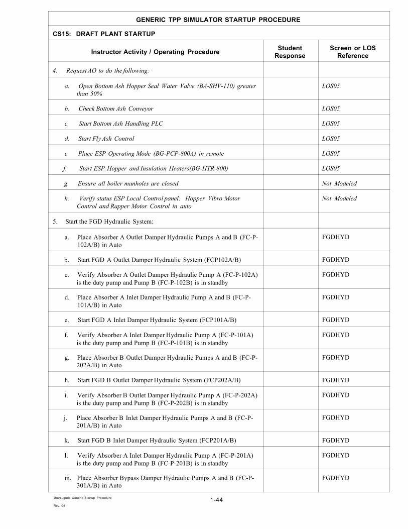
4. Request AO to do the following:
a. Open Bottom Ash Hopper Seal Water Valve (BA-SHV-110) greater than 50%
LOS05
b. Check Bottom Ash Conveyor LOS05
c. Start Bottom Ash Handling PLC LOS05
d. Start Fly Ash Control LOS05
e. Place ESP Operating Mode (BG-PCP-800A) in remote LOS05
f. Start ESP Hopper and Insulation Heaters(BG-HTR-800) LOS05
g. Ensure all boiler manholes are closed Not Modeled
h. Verify status ESP Local Control panel: Hopper Vibro Motor Control and Rapper Motor Control in auto
Not Modeled
5. Start the FGD Hydraulic System:
a. Place Absorber A Outlet Damper Hydraulic Pumps A and B (FC-P-102A/B) in Auto
FGDHYD
b. Start FGD A Outlet Damper Hydraulic System (FCP102A/B) FGDHYD
c. Verify Absorber A Outlet Damper Hydraulic Pump A (FC-P-102A) is the duty pump and Pump B (FC-P-102B) is in standby
FGDHYD
d. Place Absorber A Inlet Damper Hydraulic Pump A and B (FC-P-101A/B) in Auto
FGDHYD
e. Start FGD A Inlet Damper Hydraulic System (FCP101A/B) FGDHYD
f. Verify Absorber A Inlet Damper Hydraulic Pump A (FC-P-101A) is the duty pump and Pump B (FC-P-101B) is in standby
FGDHYD
g. Place Absorber B Outlet Damper Hydraulic Pumps A and B (FC-P-202A/B) in Auto
FGDHYD
h. Start FGD B Outlet Damper Hydraulic System (FCP202A/B) FGDHYD
i. Verify Absorber B Outlet Damper Hydraulic Pump A (FC-P-202A) is the duty pump and Pump B (FC-P-202B) is in standby
FGDHYD
j. Place Absorber B Inlet Damper Hydraulic Pumps A and B (FC-P-201A/B) in Auto
FGDHYD
k. Start FGD B Inlet Damper Hydraulic System (FCP201A/B) FGDHYD
l. Verify Absorber A Inlet Damper Hydraulic Pump A (FC-P-201A) is the duty pump and Pump B (FC-P-201B) is in standby
FGDHYD
m. Place Absorber Bypass Damper Hydraulic Pumps A and B (FC-P-301A/B) in Auto
FGDHYD
Jharsuguda Generic Startup Procedure
Rev. 04 1-44

GENERIC TPP SIMULATOR STARTUP PROCEDURE
CS15: DRAFT PLANT STARTUP
Instructor Activity / Operating Procedure Student Response
Screen or LOS Reference
n. Start Bypass Damper Hydraulic System (FCP301A/B) FGDHYD
o. Verify Absorber Bypass Damper Hydraulic Pump A (FC-P-301A) is the duty pump and Pump B (FC-P-301B) is in standby
FGDHYD
6. Open the FGD Bypass Damper (FC-GSV-301) and the FGD Bypass Damper Lower Section (FC-GSV-302)
IDFANS FCOV1
7. Verify closed all FGD inlet and outlet damper:
a. FGD A Inlet Damper (FC-GSV-101) IDFANS
b. FGD A Outlet Damper (FC-GSV-102) IDFANS
c. FGD B Inlet Damper (FC-GSV-201) IDFANS
d. FGD B Outlet Damper (FC-GSV-202) IDFANS
8. Open ID Fan A and B Inlet Dampers (BG-ISD-811A/B) IDFANS
9. Open FD Fan A and B Outlet Dampers (BG-DMP-513A/B) FDFANS
10. Close PA Fan A and B Inlet and Outlet Dampers:
a. Close PA Fan A Inlet Damper (BF-FAN-600A) PAFANS
b. Close PA Fan B Inlet Damper (BF-FAN-600B) PAFANS
c. Close PA Fan A Outlet Damper (BF-PY-602A) PAFANS
d. Close PA Fan B Outlet Damper (BF-PY-602B) PAFANS
11. Request AO to put Primary Air Heater Guide Bearing Oil Pump (BF-HS-210) in auto
LOS05
12. Request AO to put Primary Air Heater Support Bearing Oil Pump (BF-HS-230) in auto
LOS05
13. Request AO to put Secondary Air Heater A and B Guide Bearing Oil Pumps (BG-HS-310A/B) in auto
LOS05
14. Request AO to put Secondary Air Heater A and B Support Bearing Oil Pump (BG-HS-330A/B) in auto
LOS05
15. Start PA Fan A Lube Oil System:
a. Start PA Fan A Lube Oil Pump # 1 (BF-P-100A) PAFANA
b. Place PA Fan A Lube Oil Pump #2 (BF-P-101A) in auto PAFANA
c. Start PA Fan A Lube Oil Fan #1 (BF-FAN-110A) PAFANA
d. Place PA Fan A Lube Oil Fan #2 (BF-FAN-111A) in auto PAFANA
e. Perform PA Fan A Lube Oil Pump Auto Standby Start Test PAFANA
Jharsuguda Generic Startup Procedure
Rev. 04 1-45
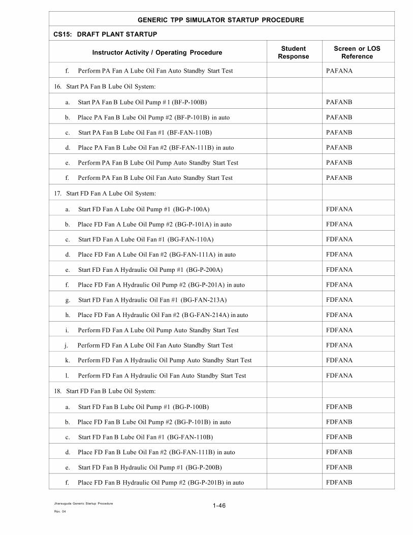
GENERIC TPP SIMULATOR STARTUP PROCEDURE
CS15: DRAFT PLANT STARTUP
Instructor Activity / Operating Procedure Student Response
Screen or LOS Reference
f. Perform PA Fan A Lube Oil Fan Auto Standby Start Test PAFANA
16. Start PA Fan B Lube Oil System:
a. Start PA Fan B Lube Oil Pump # 1 (BF-P-100B) PAFANB
b. Place PA Fan B Lube Oil Pump #2 (BF-P-101B) in auto PAFANB
c. Start PA Fan B Lube Oil Fan #1 (BF-FAN-110B) PAFANB
d. Place PA Fan B Lube Oil Fan #2 (BF-FAN-111B) in auto PAFANB
e. Perform PA Fan B Lube Oil Pump Auto Standby Start Test PAFANB
f. Perform PA Fan B Lube Oil Fan Auto Standby Start Test PAFANB
17. Start FD Fan A Lube Oil System:
a. Start FD Fan A Lube Oil Pump #1 (BG-P-100A) FDFANA
b. Place FD Fan A Lube Oil Pump #2 (BG-P-101A) in auto FDFANA
c. Start FD Fan A Lube Oil Fan #1 (BG-FAN-110A) FDFANA
d. Place FD Fan A Lube Oil Fan #2 (BG-FAN-111A) in auto FDFANA
e. Start FD Fan A Hydraulic Oil Pump #1 (BG-P-200A) FDFANA
f. Place FD Fan A Hydraulic Oil Pump #2 (BG-P-201A) in auto FDFANA
g. Start FD Fan A Hydraulic Oil Fan #1 (BG-FAN-213A) FDFANA
h. Place FD Fan A Hydraulic Oil Fan #2 (B G-FAN-214A) in auto FDFANA
i. Perform FD Fan A Lube Oil Pump Auto Standby Start Test FDFANA
j. Perform FD Fan A Lube Oil Fan Auto Standby Start Test FDFANA
k. Perform FD Fan A Hydraulic Oil Pump Auto Standby Start Test FDFANA
l. Perform FD Fan A Hydraulic Oil Fan Auto Standby Start Test FDFANA
18. Start FD Fan B Lube Oil System:
a. Start FD Fan B Lube Oil Pump #1 (BG-P-100B) FDFANB
b. Place FD Fan B Lube Oil Pump #2 (BG-P-101B) in auto FDFANB
c. Start FD Fan B Lube Oil Fan #1 (BG-FAN-110B) FDFANB
d. Place FD Fan B Lube Oil Fan #2 (BG-FAN-111B) in auto FDFANB
e. Start FD Fan B Hydraulic Oil Pump #1 (BG-P-200B) FDFANB
f. Place FD Fan B Hydraulic Oil Pump #2 (BG-P-201B) in auto FDFANB
Jharsuguda Generic Startup Procedure
Rev. 04 1-46

GENERIC TPP SIMULATOR STARTUP PROCEDURE
CS15: DRAFT PLANT STARTUP
Instructor Activity / Operating Procedure Student Response
Screen or LOS Reference
g. Start FD Fan B Hydraulic Oil Fan #1 (BG-FAN-213B) FDFANB
h. Place FD Fan B Hydraulic Oil Fan #2 (B G-FAN-214B) in auto FDFANB
i. Perform FD Fan B Lube Oil Pump Auto Standby Start Test FDFANB
j. Perform FD Fan B Lube Oil Fan Auto Standby Start Test FDFANB
k. Perform FD Fan B Hydraulic Oil Pump Auto Standby Start Test FDFANB
l. Perform FD Fan B Hydraulic Oil Fan Auto Standby Start Test FDFANB
19. Start ID Fan A Lube Oil/Hydraulic Oil System:
a. Start ID Fan A LO/HO Pump #1 (BG-P-850A) IDFANA
b. Place ID Fan A LO/HO Pump #2 (BG-P-851A) in auto IDFANA
c. Start ID Fan A LO/HO Fan #1 (BG-FAN-860A) IDFANA
d. Place ID Fan A LO/HO Fan #2 (BG-FAN-861A) in auto IDFANA
e. Start ID Fan A Seal Air Fan #1 (BG-FAN-907A) IDFANA
f. Place ID Fan A Seal Air Fan #2 (BG-FAN-908A)in auto IDFANA
g. Place ID Fan A LO/HO Heater (BG-HTR-850A) in auto IDFANA
h. Perform ID Fan A LO/HO Pump Auto Standby Start Test IDFANA
i. Perform ID Fan A LO/HO Fan Auto Standby Start Test IDFANA
20. Start ID Fan B Lube Oil/Hydraulic Oil System:
a. Start ID Fan B LO/HO Pump #1 (BG-P-850B) IDFANB
b. Place ID Fan B LO/HO Pump #2 (BG-P-851B) in auto IDFANB
c. Start ID Fan B LO/HO Fan #1 (BG-FAN-860B) IDFANB
d. Place ID Fan B LO/HO Fan #2 (BG-FAN-861B) in auto IDFANB
e. Start ID Fan B Seal Air Fan #1 (BG-FAN-907B) IDFANB
f. Place ID Fan B Seal Air Fan #2 (BG-FAN-908B)in auto IDFANB
g. Place ID Fan B LO/HO Heater (BG-HTR-850B) in auto IDFANB
h. Perform ID Fan B LO/HO Pump Auto Standby Start Test IDFANB
i. Perform ID Fan B LO/HO Fan Auto Standby Start Test IDFANB
21. Open the Primary Air Heater Gas Outlet Temperature Control Damper (BGTIC609)
PAHTR
Jharsuguda Generic Startup Procedure
Rev. 04 1-47

GENERIC TPP SIMULATOR STARTUP PROCEDURE
CS15: DRAFT PLANT STARTUP
Instructor Activity / Operating Procedure Student Response
Screen or LOS Reference
22. Fully open the Secondary Air Heater A Gas Outlet Temperature Control Damper (BGTIC507A)
SAHTR
23. Fully open the Secondary Air Heater B Gas Outlet Temperature Control Damper (BGTIC507B)
SAHTR
24. Open the Cold Secondary Air Cross Over Damper (BF-PY-605) PAFANS
25. Open the Hot Secondary Air Cross Over Damper (BF-PY-606) PAFANS
26. Start the Primary Air Heater:
a. Request AO to put Primary Air Heater Air Drive (BF-HS-600) in auto
LOS05
b. After the Primary Air Heater indicates "turning" on the OIS screen, start the Primary Air Heater electric motor (BF-HTR-600)
PAHTR
27. Start Secondary Air Heater A:
a. Request AO to put Secondary Air Heater A Air Drive (BG-HS-510A) in auto
LOS05
b. After the Secondary Air Heater A indicates "turning" on the OIS screen, start the Secondary Air Heater A electric motor (BG-HTR-510A)
SAHTR
28. Start Secondary Air Heater B:
a. Request AO to put Secondary Air Heater B Air Drive (BG-HS-510B) in auto
LOS05
b. After the Secondary Air Heater A indicates "turning" on the OIS screen, start the Secondary Air Heater A electric motor (BG-HTR-510B)
SAHTR
29. Verify that no Primary Air Heater Temperature transmitters (BGHS609, BGHS610, BGHS611) are bypassed
PASAHTRS
30. Verify that no Secondary Air Heater A Gas Outlet Temperature transmitters (BGHS586A, BGHS587A, BGHS588A) are bypassed
PASAHTRS
31. Verify that no Secondary Air Heater A Gas Outlet Temperature transmitters (BGHS586B, BGHS587B, BGHS588B) are bypassed
PASAHTRS
32. Verify all Auxiliary Air Dampers are full open WBOXOV
33. Verify the Windbox Nozzle Tilt Control (BFTIC729A) is in manual and the position is horizontal (50%)
WBOXOV
34. Verify that the SOFA Nozzle Tilt Control (BFHS730) is in manual and the position is horizontal (38%)
WBOXOV
35. Verify at least one BCW pump in service BLRCIRC
Jharsuguda Generic Startup Procedure
Rev. 04 1-48

GENERIC TPP SIMULATOR STARTUP PROCEDURE
CS15: DRAFT PLANT STARTUP
Instructor Activity / Operating Procedure Student Response
Screen or LOS Reference
36. Verify that no Furnace Pressure Transmitters (BGHS548/697/699) are bypassed
FPCNTL
Manual Draft Startup
37. Set Furnace Pressure Set Point (BGFPSETPT) to -0.15 kPag FPCNTL
38. Close ID Fan A Inlet Damper (BG-ISD-811A) IDFANS
39. Close FD Fan A Outlet Damper (BG-DMP-513A) FDFANS
40. Ensure FD Fan B Outlet Damper is open in order to get ID Fan A Start permissive (BG-DMP-513B)
FDFANS
41. Start ID Fan A (BG-FAN-500A), the ID Fan A Inlet Damper (BG-ISD-811A) will automatically open after 5 seconds.
IDFANA
42. Place ID Fan A Blade Pitch Demand (BGIDFANA) in auto IDFANA
43. Start FD Fan A (BG-FAN-510A) FDFANA
44. Open FD Fan A Outlet Damper (B G-DMP-513 A) FDFANA
45. Place FD Fan A Blade Pitch Demand (BGFDFANA) in auto FDFANA
46. Close ID Fan B Inlet Damper (BG-ISD-811B) IDFANS
47. Close FD Fan B Outlet Damper (BG-DMP-513B) FDFANS
48. Wait for the air flow to increase above 20% and for the furnace pressure to stabilize
FDFANS
49. Start ID Fan B (BG-FAN-500B), the ID Fan B Inlet Damper (BG-ISD-811B) will automatically open after 5 seconds
IDFANB
50. Place ID Fan B Blade Pitch Demand (BGIDFANB) in auto IDFANB
51. Start FD Fan B (BG-FAN-510B) FDFANB
52. Open FD Fan B Outlet Damper (BG-DMP-513B) FDFANB
53. Place FD Fan B Blade Pitch Demand (BGFDFANB) in auto FDFANB
54. Adjust the balance between ID Fans A and B by adjusting the bias of the ID Fan Blade Pitch Demand stations (BGIDFANA/B) appropriately
AIRMSTR
55. Adjust the balance between FD Fans A and B by adjusting the bias of the ID Fan Blade Pitch Demand stations (BGFDFANA/B) appropriately
AIRMSTR
56. Verify that the initial airflow is automatically established at 35% FPCNTL
57. Place the Auxiliary Air Damper Demand station (BGPDIC546/7) in auto.
WBOXOV
Jharsuguda Generic Startup Procedure
Rev. 04 1-49

GENERIC TPP SIMULATOR STARTUP PROCEDURE
CS15: DRAFT PLANT STARTUP
Instructor Activity / Operating Procedure Student Response
Screen or LOS Reference
Automatic Sequence Draft Startup
58. Verify ID Fan A Inlet Damper (BG-ISD-811A) is closed IDFANA
59. Verify FD Fan A Outlet Damper (BG-DMP-513A) is closed FDFANA
60. Verify FD Fan B Outlet Damper (BG-DMP-513B) is open FDFANS
61. Verify ID Fan A Start Permissives are satisfied HIDA
62. Start ID Fan A Start Sequence (BGIDASEQSTART), verify the following sequence occurs:
IDFANSSA
a. ID Fan A (BG-FAN-500A) starts IDFANSSA
b. ID Fan A Inlet Damper (BG-ISD-811A) opens IDFANSSA
c. ID Fan A Blade Pitch Demand (BGIDFANA) goes to its minimum and then to auto
IDFANSSA
63. Start FD fan A Start Sequence (BGFDASEQSTART), verify the following sequence occurs:
FDFANSSA
a. FD Fan A Blade Pitch Demand (BGFDFANA) goes to minimum FDFANSSA
b. FD Fan A (BG-FAN-510A) starts FDFANSSA
c. FD Fan A Outlet Damper (BG-DMP-513A) opens FDFANSSA
d. FD Fan A Blade Pitch Demand (BGFDFANA) goes to auto FDFANSSA
64. Close FD Fan B Outlet Damper (BG-DMP-513B) FDFANS
65. Verify that the air flow is automatically increasing. Wait for the air flow to increase above 20% and for the furnace pressure to stabilize
FDFANS
66. Start ID Fan B Start Sequence (BGIDBSEQSTART), verify the following sequence occurs:
IDFANSSB
a. ID Fan B (BG-FAN-500B) starts IDFANSSB
b. ID Fan B Inlet Damper (BG-ISD-811B) opens IDFANSSB
c. ID Fan B Blade Pitch Demand (BGIDFANB) goes to minimum and then to auto
IDFANSSB
67. Start FD fan B Start Sequence (BGFDBSEQSTART), verify the following sequence occurs:
FDFANSSB
a. FD Fan B Blade Pitch Demand (BGFDFANB) goes to minimum FDFANSSB
b. FD Fan B (BG-FAN-510B) starts FDFANSSB
c. FD Fan B Outlet Damper (BG-DMP-513B) opens FDFANSSB
Jharsuguda Generic Startup Procedure
Rev. 04 1-50

GENERIC TPP SIMULATOR STARTUP PROCEDURE
CS15: DRAFT PLANT STARTUP
Instructor Activity / Operating Procedure Student Response
Screen or LOS Reference
d. FD Fan B Blade Pitch Demand (BGFDFANB) goes to auto FDFANSSB
68. Adjust the balance between ID Fans A and B by adjusting the bias of the ID Fan Blade Pitch Demand stations (BGIDFANA/B) appropriately
AIRMSTR
69. Adjust the balance between FD Fans A and B by adjusting the bias of the FD Fan Blade Pitch Demand stations (BGFDFANA/B) appropriately
AIRMSTR
70. Verify that the initial airflow is automatically established at 35% FPCNTL
71. Set the Windbox/Furnace dP Bias (BGPDIC546-BIAS) to 0 WBOXOV
72. Place the Auxiliary Air Damper Demand station (BGPDIC546/7) in auto.
WBOXOV
73. After MFT be cleared, usually after Purge, Place SOFA Dampers in Auto:
a. Set SOFA A Dampers Demand station (BFFIC713) Bias to 0% WBOXOV
b. Place SOFA A Dampers Demand station (BFFIC713) in Auto WBOXOV
c. Set SOFA B Dampers Demand station (BFFIC712) Bias to 0% WBOXOV
d. Place SOFA B Dampers Demand station (BFFIC712) in Auto WBOXOV
e. Set SOFA C Dampers Demand station (BFFIC711) Bias to 0% WBOXOV
f. Place SOFA C Dampers Demand station (BFFIC711) in Auto WBOXOV
g. Set SOFA D Dampers Demand station (BFFIC710) Bias to 0% WBOXOV
h. Place SOFA D Dampers Demand station (BFFIC710) in Auto WBOXOV
CS15 FINISHED
Jharsuguda Generic Startup Procedure
Rev. 04 1-51

GENERIC TPP SIMULATOR STARTUP PROCEDURE
CS16: DRAFT PLANT INTERLOCK TEST
Instructor Activity / Operating Procedure Student Response
Screen or LOS Reference
Instructor Information: Discuss: 1. During tests avoid excessive maximum or minimum values and do not
hold at high furnace pressure or draft. 2. Make sure all boiler air/gas path inspection doors are closed. 3. Be sure to inform operations staff and personnel at boiler that draft
plant test will be performed.
Notes: 1. Normal Furnace Pressure Block Increase occurs at a furnace pressure of
+1.3kPa. Normal Furnace Draft Block Increase occurs at a furnace pressure of -1.5kPa.
2. In order to perform "I&C Temporary Modification" on the simulator, place BG-FURN-REL switch (LOS05) in the following positions: a. DRAFT to force High Draft Block b. POSITIVE to force High Furnace Pressure Block c. NO to release the force logic
3. Tests should be conducted at an air flow of 35% MCR 4. Test should be conducted with a furnace pressure setpoint -0.15kPag 5. Boiler alarm/trip condition:
a. Boiler Low Air Flow Alarm will occur when air flow < 30% b. Boiler Low Air Flow Trip MFT will occur when air flow < 25% c. Furnace Pressure Low Alarm will occur when < -1.0kPag d. Furnace Pressure Low Trip MFT will occur when < -1.75kPag e. Furnace Pressure High Alarm will occur when > +0.75kPag f. Furnace Pressure High Trip MFT and fan trip will occur when >
+1.5kPag 6. Save a temporary AV (Boiler Purge Complete) after the boiler purge is
completed to use as the basis for the Draft Plant Interlock Tests. 7. Reload the Boiler Purge Complete AV prior to successive interlock
tests in place of the last two steps of each test. 8. Verify that the Bottom Ash Seal Water Valve is open > 50% to avoid
air in leakage into the boiler (LOS05.)
7 • Questions:
Draft Test Preparation
1. Verify that Auxiliary Air Dampers are modulating and that the Auxiliary Air Damper Demand control station (BGPDIC546/7) is in AUTO mode
AUXAIR
2. Verify ID Fan Blade Pitch Demand control (BGIDFANA/B) and FD Fan Blade Pitch Demand control (BGFDFANA/B) are in auto
IDFANS FDFANS
3. Verify that the Purge Permissive "Purge Ready" has been established PURGE
Jharsuguda Generic Startup Procedure
Rev. 04 1-52

GENERIC TPP SIMULATOR STARTUP PROCEDURE
CS16: DRAFT PLANT INTERLOCK TEST
Instructor Activity / Operating Procedure Student Response
Screen or LOS Reference
4. Place Secondary Air Heater A Gas Outlet Damper control station (BGTIC507A) in auto
SAHTR
5. Place Secondary Air Heater B Gas Outlet Damper control station (BGTIC507B) in auto
SAHTR
6. Place Primary Air Heater Gas Outlet Damper control station (BGTIC609) in auto
PAHTR
7. Initiate Boiler Purge (BF-BLR-PURGE) PURGE
8. Verify that the MFT is reset when the purge is completed PURGE
Test 1: DCS MFT Push Button
9. Initiate a Boiler Emergency Trip (BF-BLR-TRIP) from the OIS PURGE
10. Verify that an MFT occurs and the boiler trips PURGE
11. Acknowledge and clear any alarms ALARMS
12. Re-initiate Boiler Purge (BF-BLR-PURGE) PURGE
13. Verify that the MFT is reset when the purge is completed PURGE
Test 2: DCS MFT Push Button
14. Initiate a Boiler Emergency Trip (BOILER TRIP) from the HPE DRUMLVL
15. Verify that an MFT occurs and the boiler trips PURGE
16. Acknowledge and clear any alarms ALARMS
17. Re-initiate Boiler Purge (BF-BLR-PURGE) PURGE
18. Verify that the MFT is reset when the purge is completed PURGE
Test 3: Low Air Flow MFT
19. Place both ID Fan Blade Pitch Demand control stations (BGIDFANA/B) in auto
IDFANS
20. Place both FD Fan Blade Pitch Demand control stations (BGFDFANA/B) in manual
FDFANS
21. Gradually decrease the FD Fan Blade Pitch Demand (BGFDFANA/B) to reduce the air flow
FDFANS
22. Verify the occurrence of the "Low Air Flow" alarm when air flow decreases below 30% MCR
ALARMS
23. Verify that an MFT occurs and the boiler trips when air flow decreases below 25%
PURGE
Jharsuguda Generic Startup Procedure
Rev. 04 1-53

GENERIC TPP SIMULATOR STARTUP PROCEDURE
CS16: DRAFT PLANT INTERLOCK TEST
Instructor Activity / Operating Procedure Student Response
Screen or LOS Reference
24. Verify MFT/First Out indicates the "Air Flow < 25%" trip PURGE
25. Return both FD Fan Blade Pitch Demand control stations (BGFDFANA/B)to auto
FDFANS
26. Acknowledge and clear any alarms ALARMS
27. Re-initiate Boiler Purge (BF-BLR-PURGE) PURGE
28. Verify that the MFT is reset when the purge is completed PURGE
Test 4: Furnace Draft High Alarms and MFT
29. Place both ID Fan Blade Pitch Demand control stations (BGIDFANA/B) in manual
IDFANS
30. Gradually increase the ID Fan Blade Pitch Demand (BGIDFANA/B) to reduce the furnace pressure
IDFANS
31. Verify the occurrence of the "Low Furnace Pressure" alarm when the furnace pressure decreases below -1.0kPag
ALARMS
32. Verify that a Furnace Pressure Low Block occurs when the furnace pressure drops below -1.55 kPag
ALARMS
33. Request I&C personnel to conduct "I&C Temporary Modification " to control logic to disable High Draft (DRAFT) block
LOS05
34. Verify that an MFT occurs and the boiler trips when the furnace pressure decreases below -1.75kPag
PURGE
35. Verify that the fan groups trip when the furnace pressure decreases below -2.25kPa
IDFANS FDFANS
36. Verify MFT/First Out indicates the "High Furnace Draft" trip PURGE
37. Acknowledge and clear any alarms ALARMS
38. Restart the ID and FD Fans
39. Re-initiate Boiler Purge (BF-BLR-PURGE) PURGE
40. Verify that the MFT is reset when the purge is completed PURGE
Test 5: Furnace Pressure High Alarms and MFT
41. Place both ID Fan Blade Pitch Demand control stations (BGIDFANA/B) in manual
IDFANS
42. Verify both FD Fan Blade Pitch Demand control stations (BGFDFANA/B) have automatically switched to manual
FDFANS
43. Gradually decrease the ID Fan Blade Pitch Demand (BGIDFANA/B) to increase the furnace pressure
IDFANS
Jharsuguda Generic Startup Procedure
Rev. 04 1-54

GENERIC TPP SIMULATOR STARTUP PROCEDURE
CS16: DRAFT PLANT INTERLOCK TEST
Instructor Activity / Operating Procedure Student Response
Screen or LOS Reference
44. Maintain airflow at 35% by increasing FD Fan Blade Pitch Demand FDFANS
45. Verify the occurrence of the "High Furnace Pressure" alarm when the furnace pressure increases above +0.75kPag
ALARMS
46. Verify that a Furnace Pressure High Block occurs when the furnace pressure drops below +1.3 kPag
ALARMS
47. Request I&C personnel to conduct "I&C Temporary Modification " to control logic to disable High Pressure (POSITIVE) block
LOS05
48. Verify that an MFT occurs and the boiler trips when the furnace pressure increases above +1.5kPag
PURGE
49. Verify that the fan groups trip when the furnace pressure increases above +1.5kPag
IDFANS FDFANS
50. Verify MFT/First Out indicates the "High Furnace Pressure" trip PURGE
51. Acknowledge and clear any alarms ALARMS
52. Restart the ID and FD Fans
Test Completion
53. Request AO to verify Bottom Ash Water Seal still established. LOS05
54. Verify ID Fan Blade Pitch Demand control stations (BGIDFANA/B) have been returned to auto
IDFANS
55. Verify FD Fan Blade Pitch Demand control stations (BGFDFANA/B) have been returned to auto
FDFANS
56. Verify furnace pressure is stable at -0.15kPag IDFANS
57. Verify air flow is stable at ~35% MCR FDFANS
CS16 FINISHED
Jharsuguda Generic Startup Procedure
Rev. 04 1-55

GENERIC TPP SIMULATOR STARTUP PROCEDURE
CS17: FINAL CHECKS FOR LIGHT OFF
Instructor Activity / Operating Procedure Student Response
Screen or LOS Reference
Instructor Information Discuss: 1. Before startup, remind CRO to verify that various transmitters have
been placed in service: a. Furnace Press Transmitters (FPCNTL) b. Drum Level Transmitters (DLSELECT) c. Drum Pressure Transmitters (DLSELECT) d. Air and Gas Temperature Transmitters (PASAHTRS) e. Main Steam Press Transmitters (MSPRESS) f. Economizer Outlet Temperature Transmitters (ECONBFPS)
Notes:
^ Questions: •
Boiler Side Checks
1. Verify that the Purge Permissive "Purge Ready" has been established. If Drum Level Satisfactory not OK, maybe it's because of Drum level Transmitter in Bypass, Place the level transmitter include please.
PURGE DLSELECT
2. Initiate Boiler Purge (BF-BLR-PURGE) PURGE
3. Verify that the MFT is reset when the purge is completed PURGE
4. Verify Fuel Oil Pump A (FO-P-700A) is in service FUELOIL
5. Verify drum level is approximately -200mm to allow for drum swell on firing
DRUMLVL
6. Verify the Windbox Nozzle Tilt Control (BFTIC729A) is in manual and the position is horizontal (50%)
WBOXOV
7. Verify that the SOFA Nozzle Tilt Control (BFHS730) is auto tracking WBOXOV
8. Ask Chemist Technician to verify boiler water quality is satisfactory (TSS < 150ppb, pH= 9.0 ~ 9.6)
Not Modeled
9. Request AO to select Air Heater Soot Blower Media as air LOS12
10. Request AO to set Air Heater Soot Blower Drain Temperature Setpoint (BS-TC-720) to 0°F when using air as the blowing media
LOS12
11. Request AO to set air heater soot blower drain temperature (BS-TC-730) at 0°F when using air as the blowing media
LOS12
12. Verify Air Heater Soot Blowers are ready to operate GSSBS-22
13. Open Economizer Recirculation Valve (FW-MOV-114) BLRCIRC
Jharsuguda Generic Startup Procedure
Rev. 04 1-56

GENERIC TPP SIMULATOR STARTUP PROCEDURE
CS17: FINAL CHECKS FOR LIGHT OFF
Instructor Activity / Operating Procedure Student Response
Screen or LOS Reference
14. Start Scanner Air Fan A (BF-SAFA) SAFANS
15. Place Scanner Air Fan B (BF-SAFB) in auto SAFANS
16. Put Furnace Thermal Probes in service and fully extended into furnace GSSBS-07
17. Verify Primary Air Heater Temperature Transmitters (BGHS609/610/611) are in service
PASAHTRS
18. Verify Secondary Air Heater A Gas Outlet Temperature Transmitters (BGHS586A/587A/588A) are in service
PASAHTRS
19. Verify Secondary Air Heater B Gas Outlet Temperature Transmitters (BGHS586B/587B/588B) are in service
PASAHTRS
20. Place Secondary Air Heater A Gas Outlet Temperature Control Damper (BGTIC507A) in auto
SAHTR
21. Place Secondary Air Heater B Gas Outlet Temperature Control Damper (BGTIC507B) in auto
SAHTR
22. Place Primary Air Heater Gas Outlet Temperature Control Damper (BGTIC609) in auto
PAHTR
23. Verify Auxiliary Air Damper Demand station (BGPDIC546/7) is in auto
WBOXOV
24. Place SOFA Dampers in auto: WBOXOV
a. SOFA D Dampers (BFFIC710) WBOXOV
b. SOFA C Dampers (BFFIC711) WBOXOV
c. SOFA B Dampers (BFFIC712) WBOXOV
d. SOFA A Dampers (BFFIC713) WBOXOV
25. Put CCOFA Dampers in auto WBOXOV
a. CCOFA B Dampers (BFFIC714) WBOXOV
b. CCOFA A Dampers (BFFIC715) WBOXOV
26. Verify that there is sufficient coal in the coal silos PULVA-F
27. Request AO to open Coal Silo Gates for Silos A-F LOS03
28. Request AO to start Coal Silo Vibrators for Silos A-F LOS03
29. Ensure all Longstroke Sootblowers and Wall sootblowers are retracted GSSBS
30. Verify the following transmitters are in service:
a. Furnace Pressure Transmitters FPCNTL
Jharsuguda Generic Startup Procedure
Rev. 04 1-57

GENERIC TPP SIMULATOR STARTUP PROCEDURE
CS17: FINAL CHECKS FOR LIGHT OFF
Instructor Activity / Operating Procedure Student Response
Screen or LOS Reference
b. Drum Level Transmitters DLSELECT
c. Air and Gas Temperature Transmitters PASAHTRS
d. Main Steam Press Transmitters MSPRESST
e. Economizer Outlet Temperature Transmitters ECONBFPS
Turbine Side Checks
31. Verify Main Turbine Lube Oil is in service LUBEOIL
32. Verify Main Turbine Hydraulic Oil Systems is in service HPU
33. Verify Stator Cooling Water System is in service SWCOOL
34. Verify Generator Core Monitor and Digital Fault Recorder are in service
Not Modeled
35. Verify Main Turbine is on Turning Gear TGEAR
36. Verify that the generator is charged with hydrogen with a pressure of ~4.5 bar and a minimum hydrogen purity of 96% If not, request AO to lineup generator gas system and charge with
Hydrogen(AP-H2), Until Hydrogen casing pressure ~4.5bar, Purity about 96%
GENOV
LOS12
37. Verify Group A Turbine Drains are open
a. HP Turbine Stop Valve 1 Inlet Drain (BS-MOV-120A) BSDRAINS
b. HP Turbine Stop Valve 2 Inlet Drain (BS-MOV-120B) BSDRAINS
c. Stop Valve 1 Above Seat Drain (TG-FY-310A) RTRWRMV1
d. Stop Valve 2 Above Seat Drain (TG-FY-310B) RTRWRMV1
e. Stop Valve 1 Below Seat Drain (TG-FY-311A) RTRWRMV1
f. Stop Valve 2 Below Seat Drain (TG-FY-311B) RTRWRMV1
g. Combined Reheat Valve 1 After Seat Drain (TG-FY-400A) RTRWRMV2
h. Combined Reheat Valve 2 After Seat Drain (TG-FY-400B) RTRWRMV2
38. Verify Group B Turbine Drains are open
a. Cold Reheat A Drain Pot 1 (BS-MOV-134A) RTRWRMV1
b. Cold Reheat B Drain Pot 1 (BS-MOV-134B) RTRWRMV1
c. Cold Reheat A Drain Pot 2 (BS-MOV-135A) RTRWRMV1
d. Cold Reheat B Drain Pot 2 (BS-MOV-135B) RTRWRMV1
Jharsuguda Generic Startup Procedure
Rev. 04 1-58

GENERIC TPP SIMULATOR STARTUP PROCEDURE
CS17: FINAL CHECKS FOR LIGHT OFF
Instructor Activity / Operating Procedure Student Response
Screen or LOS Reference
e. Hot Reheat A Drain Valve (BS-MOV-154A) RTRWRMV2
f. Hot Reheat B Drain Valve (BS-MOV-154B) RTRWRMV2
g. HP Shell Drain Valve 1 (TG-FY-200) RTRWRMV1
h. HP Shell Drain Valve 2 (TG-FY-210) RTRWRMV1
i. HP Shell Drain Valve 3 (TG-FY-220) RTRWRMV1
j. HP Shell Drain Valve 4 (TG-FY-230) RTRWRMV1
k. CV Common Drain Valve (TG-MOV-340) RTRWRMV1
39. Verify Main Turbine Valves are closed: STMVALVE
a. HP Main Stop Valve 1 (MSV1) STMVALVE
b. HP Main Stop Valve 2 (MSV2) STMVALVE
c. HP Control Valve 1 (CV1) STMVALVE
d. HP Control Valve 2 (CV2) STMVALVE
e. HP Control Valve 3 (CV3) STMVALVE
f. HP Control Valve 4 (CV4) STMVALVE
g. Reheat Intercept Valve 1 (IV1) STMVALVE
h. Reheat Intercept Valve 2 (IV2) STMVALVE
i. Reheat Stop Valve 1 (RSV1) STMVALVE
j. Reheat Stop Valve 2 (RSV2) STMVALVE
40. Place MKV to DCS Control Selection (TG-MKV-DCS) on DCS HPBYPASS
41. Verify Backpass Superheater header drains are open:
a. Backpass Roof Drain Valve (BS-MOV-220) SHDRAINS
b. Backpass Front Header Drain Valve (BS-MOV-221) SHDRAINS
c. Backpass Rear Header Drain Valve #1 (BSMOV222) SHDRAINS
d. Backpass Rear Header Drain Valve #2 (BSMOV223) SHDRAINS
e. Backpass Rear Header Drain Valve #3 (BSMOV224) SHDRAINS
42. Verify all drum and superheater vents are open until steam is flow established and indicated by increasing temperatures during boiler light-off
SHVENTS
a. Boiler Drum Vent Valve #3 (BS-MOV-205) SHVENTS
Jharsuguda Generic Startup Procedure
Rev. 04 1-59

GENERIC TPP SIMULATOR STARTUP PROCEDURE
CS17: FINAL CHECKS FOR LIGHT OFF
Instructor Activity / Operating Procedure Student Response
Screen or LOS Reference
b. Boiler Drum Vent Valve #4 (BS-MOV-210) SHVENTS
c. Intermediate SH Desuperheater A Vent Valve (BS-MOV-230A) SHVENTS
d. Intermediate SH Desuperheater B Vent Valve (BS-MOV-230B) SHVENTS
e. SH Crossover Vent Valve #1 (BS-MOV-240) SHVENTS
f. SH Crossover Vent Valve #2 (BS-MOV-276) SHVENTS
g. Final SH Desuperheater A Vent Valve (BS-MOV-250A) SHVENTS
h. Final SH Desuperheater B Vent Valve (BS-MOV-250B) SHVENTS
i. Final SH Vent Valve #1 (BS-MOV-104A) SHVENTS
j. Final SH Vent Valve #2 (BS-MOV-104B) SHVENTS
43. Request AO to verify superheater and reheater attemperator spray isolation valves are closed
a. RH Desuperheater Isolation Valve (FWISV325A) LOS07
b. RH Desuperheater Isolation Valve (FWISV325B) LOS07
c. Final SH Desuperheater Isolation Valve (FW-ISV-338B) LOS07
d. Final SH Desuperheater Isolation Valve (FW-ISV-338D) LOS07
44. Request AO to verify Auxiliary Steam to Deaerator Isolation Valve is open (AS-ISV-150)
LOS06
45. Verify Deaerator Auxiliary Steam Pressure Control station (ASPIC110) is in manual and closed
AUXSTM
46. Verify Gland Steam Blower A or B (TL-BLO-550A/B) in service STMSEAL
47. Open Unit 1/2 SH Division Panel Cross Tie (AS-MOV-104) to allow use of Unit 2 steam supply to auxiliary steam during startup
AUXSTM
48. Prepare the Auxiliary Steam line from Unit2 by flushing for at least one hour
Not Modeled
49. Request AO to place all Oil Gun Local switches in REMOTE LOS03
50. Request AO to open Main Steam to BFPT Isolating Valve (BS-SHV-105)
LOS07
51. Request AO to open IP Steam to BFPT A Isolating Valve (TG-ISV-260A)
LOS07
52. Request AO to open IP Steam to BFPT B Isolating Valve (TG-ISV-260B)
LOS07
CS17 FINISHED
Jharsuguda Generic Startup Procedure
Rev. 04 1-60

GENERIC TPP SIMULATOR STARTUP PROCEDURE
CS18: LIGHT OFF AND INCREASING PRESSURE
Instructor Activity / Operating Procedure Student Response
Screen or LOS Reference
Instructor Information Discuss:
Notes: 1. Before light off, ensure BP.4 Final Check for Light off has been
completed. 2. Boiler Light off Notes:
a. For a cold start put AB elevation oil guns in first. b. Boiler temperature ramp rate should be < 222°C/hr
(56°C/15minutes) c. Furnace exit gas temperature should be < 538°C d. For a cold start, the startup from light off to synchronous speed
shall require < 7.0 hours e. Ensure 2-4 Superheater Back Pass Drains, all Superheater Drains
and Vents, and all Reheater Vents are open. f. Place only one BCWP in service while boiler water temperature
(suction manifold temperature) is between 93-121°C. g. Perform change over of BCWP' s during rising boiler temperature
and pressure in order to keep BCWP differential temperature (between suction manifold and casing) <55°C and thus maintain the start permissive.
3. BCWP Trip Conditions: a. Motor Cavity Temperature > 60°C b. Pump Differential Pressure < 41.37kPag for > 5 sec (when three
BCW pumps are in service) c. Cooling Water Flow < 242.3 l/min
4. Keep one or tow backpass drains open until the turbine is rolling. Do not close all backpass drains before the turbine begins rolling.
1 ^ 1 Questions: 1 • 1 1. Why are the drum vents closed at 200kPag?
Answer: The drum vents are used to vent oxygen and dissolved gases from the boiler so they do not react with the boiler tubes to cause corrosion. At 200kPag, the drum is considered free of air and the venting process in complete.
1. Complete the Deaerator Pre-start Check Sheet
2. Verify Atomizing Air Pressure status indicates "ready" on OIS screen and Atomizing Air Pressure (FOPI910) is OK
ELEVAB
3. Verify Fuel Oil Pressure status indicates "ready" on OIS screen and Fuel Oil Pressure (FOPI825) is OK
ELEVAB
4. Verify Thermal Probes are in service and fully extended GSSBS-07
5. Open Warm Up Oil Trip Valve (BF-WUOTV) FUELOIL
6. Put Warm Up Oil Control station (FOFIC800) in service: FUELOIL
Jharsuguda Generic Startup Procedure
Rev. 04 1-61

GENERIC TPP SIMULATOR STARTUP PROCEDURE
CS18: LIGHT OFF AND INCREASING PRESSURE
Instructor Activity / Operating Procedure Student Response
Screen or LOS Reference
a. Set Warm Up Oil Control (FOFIC800) pressure setpoint to 900kPag
FUELOIL
b. In manual, gradually open Warm Up Oil Control Valve (FOFIC800) until Lockout status is released
FUELOIL
c. Place Warm Up Oil Control (FOFIC800) in auto FUELOIL
7. Request AO to verify Elevation AB Oil Guns are in Remote position at the local panel
LOS03
8. Start Elevation AB Oil (BF-ELEV-AB), wait for elevation start sequence to complete (all corners fired)
ELEVAB
9. Reset and Restart if any oil nozzle (corner) is not proven ELEVAB
10. Adjust Warm Up Oil Control (FOFIC800) pressure setpoint as required to maintain desired warmup rate
ELEVAB
11. Request AO to verify selected Sootblower Media is Air/MS and Sootblower Drain Temperature Setpoints (BS-TC-720/730) are set to 0°F
LOS12
12. Start Air Heater Soot Blowers in Continuous Mode using Service Air. GSSBS-07
13. When Steam Flow > 10% request AO to change Sootblower Drain Temperature Setpoints (BS-TC-720/730) to 204 °C
LOS12
14. Verify that Air Heater Sootblower automatically changeover to Main Steam when Steam Flow > 10%
GSSBS-07
15. Verify Unit 1/2 SH Division Panel Cross Tie (AS-MOV-104) is open AUXSTM
16. After Auxiliary Steam line from Unit 2 is ready, place Deaerator Auxiliary Steam Pressure Control in service:
a. Gradually warm the Deaerator by manual opening the Deaerator Auxiliary Steam Pressure Control Valve (ASPIC110)
AUXSTM
b. When the Deaerator is warmed and pressurized to ~35kPag, set the Deaerator Auxiliary Steam Pressure Control (ASPIC110) setpoint to 40kPag
AUXSTM
c. Place the Deaerator Auxiliary Steam Pressure Control (ASPIC110) in auto
AUXSTM
17. Waiting for the Main Steam Pressure and Temperature to increase STMTEMP
18. Closely monitor drum level and economizer temperature, prevent economizer from steaming, verify maximum feed water to boiler temperature differential < 111°C (feedwater temp - steam drum temp)
FWOV
19. If the Drum Level increases above +150mm, lower drum level:
a. Request AO to open Intermittent Blow Down Valve (FW-DRV-120) LOS06 Jharsuguda Generic Startup Procedure
Rev. 04 1-62

GENERIC TPP SIMULATOR STARTUP PROCEDURE
CS18: LIGHT OFF AND INCREASING PRESSURE
Instructor Activity / Operating Procedure Student Response
Screen or LOS Reference
b. Open Lower Drum Drain Valve (FW-MOV-118) BLRCIRC
20. If the Drum Level drops, request AO to open the Condensate to Boiler Fill Valve (FW-CKV-561)
LOS06
21. Closely monitor B CWP's difference between the Casing Temperature (FW-TI-762A/B/C) and the Suction Manifold Differential Temperature (FW-TI-763A/B/C) for the standby pumps
BCWPA/B/C
a. Make sure the differential temperature does not exceed 55°C BCWPA/B/C
b. Change over the pumps if the differential temperature reaches ~25°C
BLRCIRC
c. Start the second BCWP (two in service) after the drum water temperature > 121°C
H2OMENU
22. After the Main Steam Pressure > 150kPa or Steam Temperature > 120°C (whichever comes first), close the drum vents:
a. Boiler Drum Vent Valve #3 (BS-MOV-205) DRUMBD
b. Boiler Drum Vent Valve #4 (BS-MOV-210) DRUMBD
23. After the Main Steam Pressure > 150kPa, close the superheater vents:
a. Intermediate SH Desuperheater A Vent Valve (BS-MOV-230A) SHVENTS
b. Intermediate SH Desuperheater B Vent Valve (BS-MOV-230B) SHVENTS
c. SH Crossover Vent Valve #1 (BS-MOV-240) SHVENTS
d. SH Crossover Vent Valve #2 (BS-MOV-276) SHVENTS
e. Final SH Desuperheater A Vent Valve (BS-MOV-250A) SHVENTS
f. Final SH Desuperheater B Vent Valve (BS-MOV-250B) SHVENTS
g. Final SH Vent Valve #1 (BS-MOV-104A) SHVENTS
h. Final SH Vent Valve #2 (BS-MOV-104B) SHVENTS
24. The Reheater Vents (BSMOV146A/B and BSMOV300) can be closed at the same time as the superheater vents, however, they must be closed prior to starting the Condenser Vacuum System
RHVENTS
25. Keep all Main Steam Drains and Reheat Drains Open MSDRAIN RHDRAINS
26. Coordinating with Chemist Technician to check Boiler water quality. Not Modeled
CS18 FINISHED
Jharsuguda Generic Startup Procedure
Rev. 04 1-63

GENERIC TPP SIMULATOR STARTUP PROCEDURE
CS19: STEAM SEAL SYSTEM START UP
Instructor Activity / Operating Procedure Student Response
Screen or LOS Reference
Instructor Information Discuss: 1. Steam Seal can be put in service using steam from the Main Steam
System or the Auxiliary Steam System a. Using Main Steam: when the Main Steam Pressure is > 1000kPag
and the Main Steam Temperature is > 200°C. b. Using Auxiliary Steam: When Unit 2 must has sufficient steam
quality and Unit 1/2 SH Division Panel Cross Tie (AS-MOV-104) is open.
Notes: 1. Steam Seal Temperature must be maintained above 150°C and below
399°C.
^ Questions:
Steam Seal System Preparation
1. Start Gland Steam Condenser Blower A (TL-BLO-550A) STMSEAL
2. Verify GSC Blower Suction Pressure is negative (about -10inH2O). STMSEAL
3. Set Steam Seal Header Pressure setpoint (AP_SSH_CMD) to 0.30barg STMSEAL
4. Verify MKV to DCS Control Select (TG-MKV-DCS) is set to DCS STMSEAL
5. Request AO to put Steam Seal Mode to A UTO at Mark V <I> LOS06
Steam Seal System Startup Using Auxiliary Steam
6. Manually open the Auxiliary Steam Seal Header Drain Valve (TL-LY-291)
STMSEAL
7. Put the Auxiliary Steam Temperature Control station (TLTIC290) in service
a. Place the Steam Seal Desuperheater Block Valve (CM-FY-192) in auto
STMSEAL
b. Set Auxiliary Steam Temperature Control station (TLTIC290) setpoint to 310°C
STMSEAL
c. Place the Auxiliary Steam Temperature Control station (TLTIC290) in auto
STMSEAL
8. Put the Auxiliary Steam Pressure Control station (TLPIC290) in auto
a. Set Auxiliary Steam Pressure Control station (TLPIC290) setpoint to 600kPag
STMSEAL
Jharsuguda Generic Startup Procedure
Rev. 04 1-64

GENERIC TPP SIMULATOR STARTUP PROCEDURE
CS19: STEAM SEAL SYSTEM START UP
Instructor Activity / Operating Procedure Student Response
Screen or LOS Reference
b. Place the Auxiliary Steam Pressure Control station (TLPIC290) in auto
STMSEAL
c. Allow the Auxiliary Steam Header Pressure to stabilize at the setpoint
STMSEAL
d. Place the Auxiliary Steam Seal Header Drain Valve (TL-LY-291) in Auto
STMSEAL
9. Start the Steam Seal System Control (LSSON_CMD) STMSEAL
10. Gradually open Auxiliary Steam Seal Block Valve (TL-MOV-295) STMSEAL
11. Verify the Steam Seal Header Pressure (AP SSH) stabilizes between 0.30 ~ 0.32barg
STMSEAL
12. From the Steam Seal Header Divert (SSHDR-AD) select yes. The Auto Dump Enable will indicate "Active."
STMSEAL
Steam Seal System Startup Using Main Steam
13. Request AO to open Main Steam to Seal Steam Isolation Valve (BS-ISV-108)
Not Modeled
14. Verify the Steam Seal System Control (LSSON_CMD) is ON STMSEAL
15. Gradually open Steam Seal Admission Block Valve (TL-MOV-250) until full open
STMSEAL
16. Verify that Steam Seal Pressure Control Valve (TLFV270) is controlling and that the Steam Seal Header Pressure (AP_SSH) increases and stabilizes at 0.3~0.32 barg
STMSEAL
17. From the Steam Seal Header Divert (SSHDR-AD) select yes. The Auto Dump Enable will indicate "Active."
STMSEAL
Condensate Polisher A Startup
18. After the boiler water quality becomes acceptable, confirm with Chemist Technician and place Condensate Polisher A in service:
a. Open Condensate Polisher Inlet Valve (CM-MOV-414) COND1
b. Open Condensate Polisher Outlet Valve (CM-MOV-416) COND1
c. Close Condensate Polisher Bypass Valve (CM-MOV-417) COND1
CS19 FINISHED
Jharsuguda Generic Startup Procedure
Rev. 04 1-65

GENERIC TPP SIMULATOR STARTUP PROCEDURE
CS20: CONDENSER VACUUM SYSTEM STARTUP
Instructor Activity / Operating Procedure Student Response
Screen or LOS Reference
Instructor Information Discuss:
Notes: 1. During start up put all three Vacuum Pumps in service: Vacuum Pump
A to Condenser A, Vacuum Pump to Condenser B, and Vacuum Pump C to Both Condensers A and B.
2. After the unit has reached the load target and the condenser vacuum is normal, shutdown Vacuum Pump C and close both inlet valves.
3. Condenser A and B Vacuum Breaker Seal Water Valves (CM-FV-525A/B) on LOS08 should be opened > 50%.
| ? | Questions:
1. Complete all vacuum pump groups Pre Start Check Sheet
a. Prepare Condenser Vacuum Pump A for start up
b. Prepare Condenser Vacuum Pump B for start up
c. Prepare Condenser Vacuum Pump C for start up
2. Close the Reheater Vent Valves:
a. RH Outlet A Vent Valve (BS-MOV-146A) RHVENTS
b. RH Outlet A Vent Valve (BS-MOV-146B) RHVENTS
c. Reheater Vent Valve (BS-MOV-300) RHVENTS
3. Request AO to open Condenser A to Vacuum Pump A Isolation Valve (CV-ISV-200)
LOS08
4. Request AO to open Condenser A to Vacuum Pump C Isolation Valve (CV-ISV-220)
LOS08
5. Request AO to open Condenser B to Vacuum Pump B Isolation Valve (CV-ISV-215)
LOS08
6. Request AO to open Condenser B to Vacuum Pump C Isolation Valve (CV-ISV-225)
LOS08
7. Close Condenser A Vacuum Breaker (CMMOV525A) CONDVAC
8. Close Condenser B Vacuum Breaker (CMMOV525B) CONDVAC
9. Request AO to open Condenser A Vacuum Breaker Seal Water Valve (CM-FV-525A)
LOS08
Jharsuguda Generic Startup Procedure
Rev. 04 1-66

GENERIC TPP SIMULATOR STARTUP PROCEDURE
CS20: CONDENSER VACUUM SYSTEM STARTUP
Instructor Activity / Operating Procedure Student Response
Screen or LOS Reference
10. Request AO to open Condenser B Vacuum Breaker Seal Water Valve (CM-FV-525B)
LOS08
11. Start three Condenser Vacuum Pumps (CV-P-100A/B/C) one by one CONDVAC
12. Monitor the Condenser Pressure as it decreases. The Condenser evacuation process will take ~2 hours.
CONDVAC
13. After the load target is reached and the Condenser Pressure drops below 60mmHg, stop Vacuum Pump C:
CONDVAC
a. Stop Condenser Vacuum Pump C (CVP100C) CONDVAC
b. Request AO to close Condenser A to Vacuum Pump C Isolation Valve (CV-ISV-220)
LOS08
c. Request AO to close Condenser B to Vacuum Pump C Isolation Valve (CV-ISV-225)
LOS08
14. Two Vacuum Pumps will remain in service CONDVAC
CS20 FINISHED
Jharsuguda Generic Startup Procedure
Rev. 04 1-67

GENERIC TPP SIMULATOR STARTUP PROCEDURE
CS21: MOTOR DRIVEN BFP STARTUP
Instructor Activity / Operating Procedure Student Response
Screen or LOS Reference
Instructor Information Discuss: 1. At low steam flow, drum level control in auto is usually unstable. Drum
level control may placed in auto after higher and more stable steam flow has been established.
Notes: 1. MDBFP Trip Conditions:
a.
b.
Lubrication Oil Trip Set Points: - Bearing Oil Header Pressure < 50kPag - Bearing Oil Header Temperature > 60°C - Working Oil After Cooler Temperature > 120°C Fluid Coupling Side Trip Set Points:
c.
d.
2.
- Bearing Temperature > 90°C - Input & Intermediate Vibration > 150^m - Output Vibration > 120^m Motor Side Trip Set Points: - Outboard & Inboard Bearing Vibration > 70^m Pump Side Trip Set Points: - CP & A.CP Bearing Temperature > 85°C - CP & A.CP Side Mechanical Flushing Temperature > 100°C - Thrust Bearing Temperature > 75°C - Outboard & Inboard Bearing Vibration > 100^m
The Condensate Pumps are only capable of providing feedwater to the boiler for drum pressures up to 4000kPag.
[21 Questions:
1. Complete MDBFP Pump Pre-start Check Sheet
2. Request AO to open MDBFP Minimum Flow Isolating Valve (FW-ISV-210)
LOS07
3. Start MDBFP Auxiliary Lube Oil Pump (FW-P-252) MDFWP
4. Place MDBFP Suction Flow control station (FWFIC309C) in auto MDFWP
5. Verify all MDBFP Start Permissive indicate Ready HMDFWP
6. Before Drum Pressure increases above 3000kPag, start the MDBFP (FW-P-200.) Observe the following
MDFWP
a. The MDBFP starts and speed increases to 500rpm
b. The MDBFP Suction Flow Control Valve (FWFIC309C) remains full open to allow minimum flow through the pump
MDFWP
MDFWP
Jharsuguda Generic Startup Procedure
Rev. 04 1-68

GENERIC TPP SIMULATOR STARTUP PROCEDURE
CS21: MOTOR DRIVEN BFP STARTUP
Instructor Activity / Operating Procedure Student Response
Screen or LOS Reference
c. The MDBFP Discharge Check Valve (FW-FY-318C) auto opens MDFWP
7. When ready, open MDBFP Discharge Valve (FW-MOV-318F) to feed drum
MDFWP
8. Gradually increase MDBFP Demand (FWSIC242) to increase pump speed and pump discharge pressure to match with boiler pressure
MDFWP
9. Adjust feed water flow to maintain normal drum level (FWSIC242) MDFWP
10. Once steam flow (and thus feedwater demand) have stabilized at a sufficient level place the Drum Level Control (FWLIC370) in auto:
a. Set Drum Level Control (FWLIC370) setpoint to -50mm MDFWP
b. Place MDBFP Demand (FWSIC242) in auto MDFWP
c. Place Drum Level Control (FWLIC370) in auto MDFWP
d. Verify Drum Level control is stable, if not place Drum Level Control (FWLIC370) in manual and control manually
MDFWP
CS21 FINISHED
Jharsuguda Generic Startup Procedure
Rev. 04 1-69

GENERIC TPP SIMULATOR STARTUP PROCEDURE
CS22: TURBINE BYPASS SYSTEM STARTUP
Instructor Activity / Operating Procedure Student Response
Screen or LOS Reference
Instructor Information Discuss: 1. After a unit outage, boiler steam silica needs to be boiled out before
sending steam to the turbine. This is done by firing the boiler and establishing steam flow through the Turbine Bypass System. The bypass will be controlled at a target condition of 130 bar until the Chemist Technician confirms the silica boil out is complete. After boiler steam silica requirements are satisfied, the Turbine Bypass System can be shutdown.
Notes: 1. The HP Bypass if one of the following conditions occurs:
a. Condenser vacuum > 259mmHg b. HP Bypass line temperature < 121°C c. Feedwater to Reheater differential pressure < 10bar
2. When steam flow > 20%, the "Loss of Reheat Protection" will be armed. The protection will only be disarmed when an MFT occurs. Thus, in order to prevent arming, the steam flow should be maintained below 20% during operation of the Turbine Bypass System.
a Questions:
1. Verify conditions are satisfactory for starting the Turbine Bypass System:
a. Firing the Boiler with one Oil Gun Elevation in service FLMDMP
b. Main Steam Pressure ~6000kPag
c. Condenser Vacuum is established (vacuum < 90 mmHg)
HPBYPASS
COND1
d. One TDBFP or MDBFP is in service FWOV
2. Reset the Turbine Bypass System (L43BYP_TRP) HPBYPASS
3. Setup and verify the following conditions for the Turbine Bypass System:
a. HP Bypass Steam Control Mode (L83HPSV_MNPS) is in auto
b. HP Bypass Water Control Mode (L83HPW_MNPS) is in auto
HPBYPASS
HPBYPASS
c. HP Bypass Control Mode (L83HPW_AU) is in auto
d. LP Bypass Steam Control Mode (L83LPS_MNPS) is in auto
HPBYPASS
HPBYPASS
e. LP Bypass Water Control Mode (L83LPW_MNPS) is in auto HPBYPASS
f. LP Bypass Control Mode (L83HPS_AU) is in auto HPBYPASS
Jharsuguda Generic Startup Procedure
Rev. 04 1-70

GENERIC TPP SIMULATOR STARTUP PROCEDURE
CS22: TURBINE BYPASS SYSTEM STARTUP
Instructor Activity / Operating Procedure Student Response
Screen or LOS Reference
g. Set the HP Bypass Pressure Setpoint (HPSV_PR_CMD) to 5 bar above the current pressure
HPBYPASS
h. Set the LP Bypass Pressure Setpoint (LPS_SP) to 12 bar HPBYPASS
4. Start the Bypass System (L43M_BYPR) by selecting ON HPBYPASS
5. Gradually reduce the HP Bypass Pressure Setpoint (HPSV_PR_CMD) in 2 bar increments until the HP Bypass Valves start opening and the LP Bypass Pressure starts increasing
HPBYPASS
6. Increase the firing rate to increase Main Steam Pressure and steam flow by increasing the Warm Up Oil Control (FOFIC800) setpoint
WUHDR
7. Close all Backpass Drain Valves:
a. Backpass Roof Drain Valve (BSMOV220) SHDRAINS
b. Backpass Front Header Drain Valve (BSMOV221) SHDRAINS
c. Backpass Rear Header Drain Valve #1 (BSMOV222) SHDRAINS
d. Backpass Rear Header Drain Valve #2 (BSMOV223) SHDRAINS
8. Increase the HP Bypass Pressure Setpoint (HPSV_PR_CMD) as the firing rate increases
HPBYPASS
9. Continue adjusting the firing rate and the HP Bypass pressure setpoint until the Main Steam Pressure is ~130 bar and the steam flow > 10%
HPBYPASS WUHDR
10. Hold this condition until the Chemist Technician confirms that the boiler silica condition is satisfied
Not Modeled
11. Once the boiler silica condition is satisfied, shutdown the Turbine Bypass System:
a. Decrease the firing rate by decreasing the Warm Up Oil Control (FOFIC800) setpoint
WUHDR
b. As the firing rate decreases decrease the HP Bypass Pressure Setpoint (HPSV_PR_CMD) until the setpoint is 100 bar
HPBYPASS
c. Continue decreasing the firing rate until the HP Bypass Valves are closed
WUHDR HPBYPASS
d. Stop the Bypass System (L43M_BYPC) by selecting OFF HPBYPASS
CS22 FINISHED
Jharsuguda Generic Startup Procedure
Rev. 04 1-71

GENERIC TPP SIMULATOR STARTUP PROCEDURE
CS23: RESET THE MAIN TURBINE
Instructor Activity / Operating Procedure Student Response
Screen or LOS Reference
Instructor Information
Discuss:
Notes:
? Questions:
1. Check all extraction steam valves and clear any "Command Disagree" (CMDDSG) alarm indications on the valve faceplates
LPFWHOV HPFWHOV
2. Verify that the Turbine Valves are in the appropriate "tripped" position
a. Main Stop Valve 1 (MSV1) is closed STMVALVE
b. Main Stop Valve 2 (MSV2) is closed STMVALVE
c. Control Valve 1 (CV1) is closed STMVALVE
d. Control Valve 2 (CV2) is closed STMVALVE
e. Control Valve 3 (CV3) is closed STMVALVE
f. Control Valve 4 (CV4) is closed STMVALVE
g. Intercept Valve 1 (IV1) is closed STMVALVE
h. Intercept Valve 2 (IV2) is closed STMVALVE
i. Reheat Stop Valve 1 (RSV1) is closed STMVALVE
j. Reheat Stop Valve 2 (RSV2) is closed STMVALVE
k. Ventilator Valve (VV) is open STMVALVE
3. Verify all Lock Out Relays are reset LORELAY
4. Reset the Main Turbine (L86MR1_CPB) MKVMRST
5. Verify that the Master Reset button text turns to green and there are no Active Turbine Trips
MKVMRST
6. Verify that the LP Feedwater Heater Extraction Isolation Valves open:
a. FWH 2 A Steam Isolation Valve (HB-MOV-295A) LPFWHOV
b. FWH 2 B Steam Isolation Valve (HB-MOV-295B) LPFWHOV
c. FWH 3 Steam Isolation Valve (HB-MOV-283) LPFWHOV
d. FWH 4 Steam Isolation Valve (HB-MOV-271) LPFWHOV
Jharsuguda Generic Startup Procedure
Rev. 04 1-72

GENERIC TPP SIMULATOR STARTUP PROCEDURE
CS23: RESET THE MAIN TURBINE
Instructor Activity / Operating Procedure Student Response
Screen or LOS Reference
7. Verify that the LP Feedwater Heater Extraction Check Valves faceplates indicate an OPEN command, but the valve position feedback indicates closed:
a. FWH 2 Extraction Check Valve A (HB-SY-296A) LPFWHOV
b. FWH 2 Extraction Check Valve B (HB-SY-296B) LPFWHOV
c. FWH 3 Extraction Check Valve (HB-SY-284) LPFWHOV
d. FWH 4 Extraction Check Valve (HB-SY-272) LPFWHOV
e. Deaerator Extraction Check Valve #1 (HB-SY-245) DEAOV
f. Deaerator Extraction Check Valve #2 (HB-SY-249) DEAOV
8. Verify HP Feedwater Heater Extraction Steam Check Valves are open:
a. FWH 6A Extraction Steam Check Valve (HB-SY-232A) HPFWHA
b. FWH 7A Extraction Steam Check Valve (HB-SY-219A) HPFWHA
c. FWH 8A Extraction Steam Check Valve (HB-SY-206A) HPFWHA
d. FWH 6B Extraction Steam Check Valve (HB-SY-232B) HPFWHB
e. FWH 7B Extraction Steam Check Valve (HB-SY-219B) HPFWHB
f. FWH 8B Extraction Steam Check Valve (HB-SY-206B) HPFWHB
9. Place the LP Feedwater Heater Level Control stations in auto:
a. FWH 2 Normal Level Control (HDLIC644) LPFWHOV
b. FWH 2 Emergency Level Control (HDLIC645) LPFWHOV
c. FWH 3 Normal Level Control (HDLIC636) LPFWHOV
d. FWH 3 Emergency Level Control (HDLIC637) LPFWHOV
e. FWH 4 Normal Level Control (HDLIC628) LPFWHOV
f. FWH 4 Emergency Level Control (HDLIC629) LPFWHOV
CS23 FINISHED
Jharsuguda Generic Startup Procedure
Rev. 04 1-73

GENERIC TPP SIMULATOR STARTUP PROCEDURE
CS24: MAIN TURBINE ROTOR WARMING
Instructor Activity / Operating Procedure Student Response
Screen or LOS Reference
Instructor Information Discuss: 1.
2.
Rotor Warming should take 4-6 hours depending on the starting rotor temperatures and the warming rate. During turbine rotor warming the CRO should proceed to warm the BFPT's, prepare the PA Fans for startup and lineup and fill the FGD sea water system.
Notes: 1. Main Turbine Rotor Pre-Warming Requirements:
a. HP Rotor Bore Temperature > 176°C b. RHT Inlet Rotor Bore Temperature > 54.4°C c. RHT Exhaust Rotor Bore Temperature > 54.4°C
2. Main Turbine Rotor Warming Operating Parameter Limits: a. Maximum Turbine Speed = 23rpm. b. Maximum Warming Rate = 38°C/hr c. Maximum MSV2 opening = 2.95% d. Chest pressure = ~12bar
3. Main Turbine Rotor Warming Operating Parameter Limits:
^ Questions: ' 1. List the Main Turbine Wanning valves and give the purpose of each? Answer:
- Main Stop Valve Bypass Valve - The MSV Bypass valve provides main steam flow to the control valve chest during rotor warming and chest warming.
- Reverse Flow Valve (RFV) - The Reverse Flow Valve provides warming flow through the HP turbine from the reheater during operation in Reverse Flow.
- Heating Steam Feed Valve (HSFV) - This valve admits packing steam from the steam seal header to the midspan of the double flow reheat turbine section to pre-warm the intermediate pressure
Jharsuguda Generic Startup Procedure
Rev. 04 1-74

GENERIC TPP SIMULATOR STARTUP PROCEDURE
CS24: MAIN TURBINE ROTOR WARMING
Instructor Activity / Operating Procedure Student Response
Screen or LOS Reference
rotor. - Heating Steam Block Valve (HSBV) - This valve will admit steam
leak-off from the HP Turbine to the Deaerator. The valve will open when the IV's open > 20%.
1. Verify that the Main Steam temperature is within the recommended range for rotor warming
LOADCR
2. Close the following Drain and Vent Valves between the CV's and the IV's by first placing the valve in manual and then closing the valve:
a. Stop Valve 1 Below Seat Drain (TG-FY-311A) RTRWRMV1
b. Stop Valve 2 Below Seat Drain (TG-FY-311B) RTRWRMV1
c. Cold Reheat A Drain Pot 1 (BS-MOV-134A) RTRWRMV1
d. Cold Reheat B Drain Pot 1 (BS-MOV-134B) RTRWRMV1
e. Cold Reheat A Drain Pot 2 (BS-MOV-135A) RTRWRMV1
f. Cold Reheat B Drain Pot 2 (BS-MOV-135B) RTRWRMV1
g. HP Shell Drain Valve 1 (TG-FY-200) RTRWRMV1
h. HP Shell Drain Valve 2 (TG-FY-210) RTRWRMV1
i. HP Shell Drain Valve 3 (TG-FY-220) RTRWRMV1
j. HP Shell Drain Valve 4 (TG-FY-230) RTRWRMV1
k. CV Common Drain Valve (TG-MOV-340) RTRWRMV1
l. HP Bypass A Outlet Drain Valve (BS-MOV- 116A) RTRWRMV1
m. HP Bypass B Outlet Drain Valve (BS-MOV-116B) RTRWRMV1
n. Reheat Desuperheater A Outlet Valve (BS-MOV-290A) RTRWRMV2
o. Reheat Desuperheater B Outlet Valve (BS-MOV-290B) RTRWRMV2
p. Hot Reheat A Drain Valve (BS-MOV-154A) RTRWRMV2
q. Hot Reheat B Drain Valve (BS-MOV-154B) RTRWRMV2
r. Combined Reheat Valve 1 After Seat Drain (TG-FY-400A) RTRWRMV2
s. Combined Reheat Valve 2 After Seat Drain (TG-FY-400B) RTRWRMV2
t. RH Outlet A Vent Valve (BS-MOV-146A) RTRWRMV2
u. RH Outlet B Vent Valve (BS-MOV-146B) RTRWRMV2
v. Reheater Vent Valve (BS-MOV-300) RTRWRMV2
Jharsuguda Generic Startup Procedure
Rev. 04 1-75

GENERIC TPP SIMULATOR STARTUP PROCEDURE
CS24: MAIN TURBINE ROTOR WARMING
Instructor Activity / Operating Procedure Student Response
Screen or LOS Reference
3. Confirm with the Chemist Technician that steam quality is satisfactory for turbine rotor warming: Silica: <10ppb, Sodium: < 3ppb, cation conductivity: < 0.2ps/cm
Not Modeled
4. Verify the Main Turbine is Reset (L86MR1_CPB) MKVMRST
5. Initiate the Rotor Warming Request command (L43RWR) RTRWARM
6. Verify that all Main Turbine CV's fully open STMVALVE
7. Verify that the HSFV is open STMVALVE
8. Close FWH 8A/8B Before Isolation Drain Valves (HB-FY-204A/B) by placing in manual and then closing the valves
RTRWRMV1
9. Gradually open Main Stop Valve #2 Bypass Valve (SVR_BS2) in 0.2% increments
RTRWARM
10. As the Main Stop Valve #2 Bypass valve is opened, the chest pressure (CP_CHST) and HP Exhaust Pressure (TP_HPE_DPY) will increase and the turbine may lift off the turning gear. The MSV2 Bypass valve should be positioned:
RTRWARM
a. Limit Main Turbine Speed to ~20 rpm RTRWARM
b. Limit Chest Pressure to ~12 barg RTRWARM
11. Record first stage shell metal temperature before rotor warming and determine rotor warming hold time based the curve in note 3, above.
12. After the HP turbine shell is pressurized, open the HP Shell Drain Valves one-by-one for a few second to release any condensation inside the turbine:
RTRWRMV1
a. HP Shell Drain Valve 1 (TG-FY-200) RTRWRMV1
b. HP Shell Drain Valve 2 (TG-FY-210) RTRWRMV1
c. HP Shell Drain Valve 3 (TG-FY-220) RTRWRMV1
d. HP Shell Drain Valve 4 (TG-FY-230) RTRWRMV1
13. Rotor Warming is complete when the Rotor Bore Temperatures are above the target values and when the Rotor Warming Required status indicates "NO"
RTRWARM
14. After Rotor Warming is complete, initiate the Rotor Warming Cancel command (L43RWC)
RTRWARM
15. Verify that all Main Turbine CV's close STMVALVE
16. Verify that the HSFV closes STMVALVE
17. Put the following Drain and Vent Valves between the CV's and the IV's in auto:
Jharsuguda Generic Startup Procedure
Rev. 04 1-76

GENERIC TPP SIMULATOR STARTUP PROCEDURE
CS24: MAIN TURBINE ROTOR WARMING
Instructor Activity / Operating Procedure Student Response
Screen or LOS Reference
a. Cold Reheat A Drain Pot 1 (BS-MOV-134A) RTRWRMV1
b. Cold Reheat B Drain Pot 1 (BS-MOV-134B) RTRWRMV1
c. Cold Reheat A Drain Pot 2 (BS-MOV-135A) RTRWRMV1
d. Cold Reheat B Drain Pot 2 (BS-MOV-135B) RTRWRMV1
e. HP Shell Drain Valve 1 (TG-ISV-200) RTRWRMV1
f. HP Shell Drain Valve 2 (TG-ISV-210) RTRWRMV1
g. HP Shell Drain Valve 3 (TG-ISV-220) RTRWRMV1
h. HP Shell Drain Valve 4 (TG-ISV-230) RTRWRMV1
i. CV Common Drain Valve (TG-MOV-340) RTRWRMV1
j. HP Bypass A Outlet Drain Valve (BS-MOV- 116A) RTRWRMV1
k. HP Bypass B Outlet Drain Valve (BS-MOV-116B) RTRWRMV1
l. FWH 8A Before Isolation Drain Valves (HB-FY-204A) RTRWRMV1
m. FWH 8B Before Isolation Drain Valves (HB-FY-204B) RTRWRMV1
n. Reheat Desuperheater A Outlet Valve (BS-MOV-290A) RTRWRMV2
o. Reheat Desuperheater B Outlet Valve (BS-MOV-290B) RTRWRMV2
p. Hot Reheat A Drain Valve (BS-MOV-154A) RTRWRMV2
q. Hot Reheat B Drain Valve (BS-MOV-154B) RTRWRMV2
r. Combined Reheat Valve 1 After Seat Drain (TG-ISV-400A) RTRWRMV2
s. Combined Reheat Valve 2 After Seat Drain (TG-ISV-400B) RTRWRMV2
t. RH Outlet A Vent Valve (BS-MOV-146A), and Close RTRWRMV2
u. RH Outlet A Vent Valve (BS-MOV-146A) , and Close RTRWRMV2
v. Reheater Vent Valve (BS-MOV-300) , and Close RTRWRMV2
18. Verify that the Main Turbine coasts back on turning gear TGEAR
CS24 FINISHED
Jharsuguda Generic Startup Procedure
Rev. 04 1-77

GENERIC TPP SIMULATOR STARTUP PROCEDURE
CS25: BFPT WARMING
Instructor Activity / Operating Procedure Student Response
Screen or LOS Reference
Instructor Information Discuss: 1. In order to save time during the startup, the first BFPT may be warmed
during the rotor warming period.
Notes:
Questions:
BFPT A Warming
1. Complete TDBFP A Pre-start Check Sheet
2. Request AO to open TDBFP A Min Flow Isolation Valve (FW-ISV-150) LOS07
3. Request AO to verify Main Steam to BFPT Isolation Valve (BS-SHV-105) is open
LOS07
4. Request AO to verify IP Steam to BFPT A Isolation valve (TG-ISV-260A) is open
LOS07
5. Request AO to place BFPT A Turning Gear (FW-TGR-100A) in auto LOS07
6. Request AO to open BFPT A Exhaust Valve (HB-FY-266A) LOS07
7. Open the following BFPT A Steam Drains and place in auto:
a. BFPT A Steam Supply Drain Valve (BS-MOV-114A) FWPA
b. BFPT A HP Stop Valve Drain #1 (TG-MOV-113A) FWPA
c. BFPT A HP Stop Valve Drain #2 (TG-MOV-114A) FWPA
d. BFPT A LP Stop Valve Drain #1 (TG-MOV-111A) FWPA
e. BFPT A LP Stop Valve Drain #2 (TG-MOV-112A) FWPA
f. BFPT A First Stage Drain (TG-MOV-115A) FWPA
8. Check Turbine Driven Feed Pump A Start Permissives display and verify BFPT A is ready
HFWPA
9. Reset TD BFP A (TGTRB100A) and verify the following events occur FWPA
a. Verify that the TD BFP A (TGTRB100A) faceplate display indicates Reset
FWPA
b. Verify that the BFPT A HP and LP Stop Valves open FWPA
c. Verify that BFPT A Control Valves remain closed FWPA
Jharsuguda Generic Startup Procedure
Rev. 04 1-78

GENERIC TPP SIMULATOR STARTUP PROCEDURE
CS25: BFPT WARMING
Instructor Activity / Operating Procedure Student Response
Screen or LOS Reference
10. Warming will be complete when the temperature difference between the Inlet Steam Temperature and the BFPT A CV Casing Metal Temperature is less than 80°C (Casing Metal Temperature Not Low indicates Ready)
HFWPA
BFPT B Warming
11. Complete TDBFP B Pre-start Check Sheet
12. Request AO to open TDBFP A Min Flow Isolation Valve (FW-ISV-160) LOS07
13. Request AO to verify IP Steam to BFPT B Isolation valve (TG-ISV-260B) is open
LOS07
14. Request AO to place BFPT B Turning Gear (FW-TGR-100B) in auto LOS07
15. Request AO to open BFPT B Exhaust Valve (HB-FY-266B) LOS07
16. Open the following BFPT B Steam Drains and place in auto:
a. BFPT B Steam Supply Drain Valve (BS-MOV-114B) FWPB
b. BFPT B HP Stop Valve Drain #1 (TG-MOV-113B) FWPB
c. BFPT B HP Stop Valve Drain #2 (TG-MOV-114B) FWPB
d. BFPT B LP Stop Valve Drain #1 (TG-MOV- 111B) FWPB
e. BFPT B LP Stop Valve Drain #2 (TG-MOV-112B) FWPB
f. BFPT B First Stage Drain (TG-MOV-115B) FWPB
17. Check Turbine Driven Feed Pump B Start Permissives display and verify BFPT B is ready
HFWPB
18. Reset TD BFP B (TGTRB100B) and verify the following events occur: FWPB
a. Verify that the TD BFP B (TGTRB100A) faceplate display indicates Reset
FWPB
b. Verify that the BFPT B HP and LP Stop Valves open FWPB
c. Verify that BFPT B Control Valves remain closed FWPB
19. Warming will be complete when the temperature difference between the Inlet Steam Temperature and the BFPT B CV Casing Metal Temperature is less than 80°C (Casing Metal Temperature Not Low indicates Ready)
HFWPB
CS25 FINISHED
Jharsuguda Generic Startup Procedure
Rev. 04 1-79

GENERIC TPP SIMULATOR STARTUP PROCEDURE
CS26: PRIMARY AIR FAN STARTUP
Instructor Activity / Operating Procedure Student Response
Screen or LOS Reference
Instructor Information Discuss:
Notes: 1. The Primary Air Fans can be prepared during turbine rotor warming and
started after rotor warming is complete. 2. Before placing PA Fan Bias Station in auto, confirm bias is < 50%. If >
50%, manually increase the output to reduce below 50%.
" t | Questions:
PA Fan Preparation
1 Verify the PA Fan Lube Oil Systems are in service: PAFANA
a. PA Fan A Lube Oil Pump #1 (BF-P-100A) is running PAFANA
b. PA Fan A Lube Oil Pump #2 (BF-P-101A) is in auto PAFANA
c. PA Fan A Lube Oil Fan # 1 (BF-FAN-110A) is running PAFANA
d. PA Fan A Lube Oil Fan #2 (BF-FAN-111A) is in auto PAFANA
e. PA Fan B Lube Oil Pump #1 (BF-P-100B) is running PAFANB
f. PA Fan B Lube Oil Pump #2 (BF-P-101B) is in auto PAFANB
g. PA Fan B Lube Oil Fan # 1 (BF-FAN-110B) is running PAFANB
h. PA Fan B Lube Oil Fan #2 (BF-FAN-111B) is in auto PAFANB
2 Verify PA Fan Start Permissives are satisfied HPA
3 Verify Hot and Cold Secondary Air Crossover Dampers (BF-PY-605A/606A) are open
PAFANS
4 Issue a PA Fan Request to Start (BF PA FAN RTS) and verify the following events:
PAFANS
a. All Pulverizer Cold Air Dampers (BFFIC666A through F) are closed to 5%
PAFANA/B/C/D/E/F
PA Fan Manual Start
5 Verify PA Fan A Bias Station is in manual and the PA Fan A Inlet Dampers (BF-FCD-600A/601A) are closed
PAFANA
6 Verify PA Fan A Outlet Damper (BF-PY-602A) is closed PAFANA
7 Start PA Fan A (BF-FAN-600A) PAFANA
Jharsuguda Generic Startup Procedure
Rev. 04 1-80

GENERIC TPP SIMULATOR STARTUP PROCEDURE
CS26: PRIMARY AIR FAN STARTUP
Instructor Activity / Operating Procedure Student Response
Screen or LOS Reference
8. Verify Seal Air Booster Fan A (BF-SABFA) auto starts SAFANS
9. Open the Cold Air Gate for at least one pulverizer: Pulverizer A (BFPY664A)
PULVA
10. Open PA Fan A Outlet Damper (BF-PY-602A) PAFANS
11. Verify Cold Secondary Air Crossover Damper (BF-PY-605A) automatically closes
PAFANS
12. Verify Hot Secondary Air Crossover Damper (BF-PY-606A) automatically closes
PAFANS
13. Increase PA Fan A Bias Station demand until PA Fan to Furnace DP (BF-PDI-683/4) is ~7.5kPag
PAFANS
14. Place PA Fan A Bias Station in auto PAFANA
15. Open remaining Pulverizer Cold Air Gates (if any):
a. Pulverizer A Cold Air Gate (BF-PY-664A) PULVA
b. Pulverizer B Cold Air Gate (BF-PY-664B) PULVB
c. Pulverizer C Cold Air Gate (BF-PY-664C) PULVC
d. Pulverizer D Cold Air Gate (BF-PY-664D) PULVD
e. Pulverizer E Cold Air Gate (BF-PY-664E) PULVE
f. Pulverizer F Cold Air Gate (BF-PY-664F) PULVF
16. Verify PA Fan B Bias Station is in manual and the PA Fan B Inlet Dampers (BF-FCD-600B/601B) are closed
PAFANB
17. Verify PA Fan B Outlet Damper (BF-PY-602B) is closed PAFANB
18. Start PA Fan B (BF-FAN-600B) PAFANB
19. Open PA Fan B Outlet Damper (BF-PY-602B) PAFANB
20. Place PA Fan B Bias Station in auto PAFANB
21. Adjust the balance between PA Fans A and B by adjusting the bias of the PA Fan B Bias Stations appropriately
AIRMSTR
PA Fan Automatic Sequence Startup
22. Verify PA Fan A Start Permissives are satisfied HPA
23. Verify PA Fan A Outlet Damper (BF-PY-602A) is closed PAFANA
24. Start PA Fan A Start Sequence (BGPAASEQSTART), verify the following sequence occurs:
PAFANSSA
Jharsuguda Generic Startup Procedure
Rev. 04 1-81

GENERIC TPP SIMULATOR STARTUP PROCEDURE
CS26: PRIMARY AIR FAN STARTUP
Instructor Activity / Operating Procedure Student Response
Screen or LOS Reference
a. PA Fan A (BF-FAN-600A) starts PAFANSSA
b. PA Fan A Outlet Damper (BF-PY-602A) open PAFANSSA
c. PA Fan A Bias Station lock is released and Inlet Dampers remain closed
PAFANSSA
25. Place PA Fan A Bias Station in auto, the Inlet Dampers will automatically open to control PA to Furnace dP to the setpoint
PAFANS
26. Verify Seal Air Booster Fan A (BF-SABFA) auto starts SAFANS
27. Verify Cold Secondary Air Crossover Damper (BF-PY-605A) automatically closes
PAFANS
28. Verify Hot Secondary Air Crossover Damper (BF-PY-606A) automatically closes
PAFANS
29. Open Pulverizer Cold Air Gates:
a. Pulverizer A Cold Air Gate (BF-PY-664A) PULVA
b. Pulverizer B Cold Air Gate (BF-PY-664B) PULVB
c. Pulverizer C Cold Air Gate (BF-PY-664C) PULVC
d. Pulverizer D Cold Air Gate (BF-PY-664D) PULVD
e. Pulverizer E Cold Air Gate (BF-PY-664E) PULVE
f. Pulverizer F Cold Air Gate (BF-PY-664F) PULVF
30. Verify PA Fan B Outlet Damper (BF-PY-602B) is in auto PAFANB
31. Start PA Fan B Start Sequence (BGPABSEQSTART), verify the following sequence occurs:
PAFANSSB
a. PA Fan B (BF-FAN-600B) starts PAFANSSB
b. PA Fan B Outlet Damper (BF-PY-602B) opens PAFANSSB
c. PA Fan B Bias Station goes to manual and PA Fan Inlet Dampers close
PAFANSSB
32. Place PA Fan B Bias Station in auto PAFANS
33. Adjust the balance between PA Fans A and B by adjusting the bias of the PA Fan B Bias Stations appropriately
AIRMSTR
Flyash Handling Startup
34. Request AO to Start Flyash Handling System LOS05
CS26 FINISHED
Jharsuguda Generic Startup Procedure
Rev. 04 1-82

GENERIC TPP SIMULATOR STARTUP PROCEDURE
CS27: PULVERIZER WARMING
Instructor Activity / Operating Procedure Student Response
Screen or LOS Reference
Instructor Information Discuss: 1. Each pulverizer needs to be warmed before coal is fed into the
pulverizer. Adequate warming requires that the outlet temperature of the pulverizer be maintained at >60°C for at least 15 minutes.
2. At low loads (low Hot Primary Air Temperature) only one pulverizer can be warmed at a time. Warming for the next pulverizer can be initiated once the first pulverizer is placed in service with a feeder demand > 30%. After two pulverizers are in service, it is possible to warm two pulverizers at a time.
3. Pulverizers should be warmed in the sequence in which they will be put in service. The typical sequence for placing Pulverizers in operation during a Cold Start is as follows: a. Pulverizer B b. Pulverizer C c. Pulverizer D d. Pulverizer A e. Pulverizer E
Notes: 1—| | • | Questions:
1. Complete Pulverizers Pre-start Check Sheets:
a. To prepare Pulverizer A for service
b. To prepare Pulverizer B for service
c. To prepare Pulverizer C for service
d. To prepare Pulverizer D for service
e. To prepare Pulverizer E for service
f. To prepare Pulverizer F for service
Pulverizer B Warming
2. Verify Pulverizer B Lube Oil System is in service and Lube Oil Temperature > 35°C
HPULVBR1
3. Request AO to open Seal Air to Coal Feeder Valve (BF-ISV-515B) LOS04
4. Verify Pulverizer B Seal Air Valve (BF-PULVB-SAV) faceplate command indicates Open
PULVB
5. Request AO to Put Coal Feeder B OP Mode to REMOTE(BF-FDR-500B)
LOS04
Jharsuguda Generic Startup Procedure
Rev. 04 1-83

GENERIC TPP SIMULATOR STARTUP PROCEDURE
CS27: PULVERIZER WARMING
Instructor Activity / Operating Procedure Student Response
Screen or LOS Reference
6. Request AO to Open Inerting steam Block Valve B(BS-FV-210B) LOS06
7. Open Pulverizer B Discharge Valves (BFFY509B) PULVB
8. Verify Pulverizer B Start permissive is satisfied HPULVBR1
9. Start Pulverizer B (BF-PVR-500B) PULVB
10. Verify Pulverizer B Seal Air Valve (BF-PULVB-SAV) auto opens PULVB
11. Verify Pulverizer B PA Flow Control station (BFFIC666B) opens and wait for air flow to increase to the setpoint
PULVB
12. Open Pulverizer B Hot Air Gate (BF-PY-662B) PULVB
13. Place Pulverizer B PA Flow Control station (BFTIC666B) in auto PULVB
14. Place Pulverizer B Temperature Control station (BFTIC586B) in auto:
a. Set Pulverizer B Temperature Control station (BFTIC586B) setpoint to 72°C
PULVB
b. Place Pulverizer B Temperature Control station (BFTIC586B) in auto
PULVB
15. Pulverizer Warming will be complete when the Pulverizer Outlet Temperature (BFTIC586B) has been maintained at >66°C for at least 15 minutes
PULVB
CS27 FINISHED
Jharsuguda Generic Startup Procedure
Rev. 04 1-84

GENERIC TPP SIMULATOR STARTUP PROCEDURE
CS28: BFPT A STARTUP
Instructor Activity / Operating Procedure Student Response
Screen or LOS Reference
Instructor Information Discuss:
Notes: 1. BFPT startup notes:
a. Do not attempt to start or operate the turbine under any circumstances without the Emergency Oil Pump in the "ready" position. Serious equipment damage and consequential personal injury may result due to loss of oil pressure.
b. Do not operate the turbine boiler feed pump with oil reservoir temperature below 37.8°C to assure proper suction condition for the emergency oil pump.
c. At low steam flow, AUTO drum level control usually not controlling properly. Drum level control may put on AUTO later after higher and more stable steam flow
d. Prior to put BFPT in service, warming is required to reduce differential temperature between BFPT steam inlet and BFPT casing metal. The differential temperature shall less than 80°C.
2. BFP Pump-side trip setpoints: a. Outboard & inboard bearing high vibration > 120^m b. CP & A.CP bearing high temp > 85°C c. Thrust bearing high temp > 75°C d. CP & A.CP side mechanical flushing high temp > 100°C
3. BFP Turbine-side trip setpoints: a. HP bearing high vibration > 152^m b. LP bearing high vibration > 152^m c. Rotor Axial position > +0.81 or < -0.81 d. Exhaust Steam press > 295 ~ 320mmHg e. Exhaust steam high temp > 204.4°C
4. The BFPT Speed Pickups do not work correctly at speeds less than 500rpm. Prior to reaching that speed the speed indication on the OIS screen will indicate 0.
[7] Questions:
1. Verify BFPT A Warming is complete FWPA
2. Check Turbine Driven Feed Pump A Start Permissives display and verify BFPT A is ready to start
HFWPA
3. Verify BFPT A Lube Oil Temperature Control (CCTIC838) is in auto and Lube Oil Temperature is above 37.8°C
FWPA
4. Place TD BFP A Suction Flow Control station (FWFIC309A) in auto FWPA
5. Place BFPT A Discharge Check Valve (FWFY318A) in auto (FW-FY-318A)
FWPA
Jharsuguda Generic Startup Procedure
Rev. 04 1-85

GENERIC TPP SIMULATOR STARTUP PROCEDURE
CS28: BFPT A STARTUP
Instructor Activity / Operating Procedure Student Response
Screen or LOS Reference
6. Verify BFPT A Emergency Lube Oil Pump (LT-P-250A) is on standby FWPA
7. Start TD BFP A (TGTRB100A) FWPA
8. After starting, the BFPT A Control Valves will open and bring the BFPT Speed to the minimum speed of 500rpm
FWPA
9. After starting the BFPT A observe the following events occur: FWPA
a. BFPT A starts and after a delay speed signal indicates ~500rpm FWPA
b. The TD BFP A Suction Flow Control Valve (FWFIC309A) remains full open to allow minimum flow through the pump
FWPA
10. Open the BFPT A Discharge Check Valve (FW-FY-318A), if cannot open, set auto and set to manual again, then open it.
FWPA
11. Change BFPT A Lube Oil Temperature Control (CCTIC838) setpoint to 50°C
FWPA
12. Open the BFPT A Discharge Valve (FW-MOV-318D) FWPA
13. Gradually increase TD BFP A Demand (TGSIC100A) to increase pump speed and pump discharge pressure to match with the current MDBFP outlet pressure
DRUMLVL
14. Verify all BFPT A Drains is close automatically when BFPT Speed > 1200rpm:
FWPA
a. BFPT A Steam Supply Drain Valve (BS-MOV-114A) FWPA
b. BFPT A HP Stop Valve Drain #1 (TG-MOV-113A) FWPA
c. BFPT A HP Stop Valve Drain #2 (TG-MOV-114A) FWPA
d. BFPT A LP Stop Valve Drain #1 (TG-MOV-111A) FWPA
e. BFPT A LP Stop Valve Drain #2 (TG-MOV-115A) FWPA
f. BFPT A First Stage Drain (TG-MOV-113A) FWPA
15. After TD BFP A speed has increased sufficiently to provide feedwater to the drum, adjust TD BFP A Demand (TGSIC100A) to maintain normal drum level
DRUMLVL
16. Verify MDBFP gradually withdraws as BFPT A maintains drum level stable
DRUMLVL
17. Place TD BFP A Demand (TGSIC100A) in auto DRUMLVL
18. Place MD BFP Demand (TGSIC242) in manual DRUMLVL
19. Gradually reduce MD BFP Demand (TGSIC242) to 0% DRUMLVL
20. Stop the MD Boiler Feed Pump (FW-P-200) MDFWP
Jharsuguda Generic Startup Procedure
Rev. 04 1-86

GENERIC TPP SIMULATOR STARTUP PROCEDURE
CS28: BFPT A STARTUP
Instructor Activity / Operating Procedure Student Response
Screen or LOS Reference
CS28 FINISHED
Jharsuguda Generic Startup Procedure
Rev. 04 1-87

GENERIC TPP SIMULATOR STARTUP PROCEDURE
CS29: MAIN TURBINE CHEST WARMING
Instructor Activity / Operating Procedure Student Response
Screen or LOS Reference
Instructor Information Discuss:
Notes: 1. Turbine Chest Warming metal temperature:
a. Chest warming is required to reduce CV inner to outer metal differential temperature and main steam to CV outer metal differential temperature.
b. During chest warming the heat soak is effective if the pressure ratio (Chest pressure/Main steam pressure) > 85%.
c. Main turbine should be on turning gear during chest warming d. Maximum differential temperature between CV Inner and Outer
Metal temperatures = 168°C e. Maximum differential temperature between Main Steam and CV
Outer Metal temperatures = 185°C
p y j Questions:
1. Check if Chest Warming is required. If required, initiate the next step. If not required, CS29 may be skipped.
CHSTWARM
2. Initiate the Chest Warming Request command (L43CWR) CHSTWARM
3. Verify that the Main Stop Valve Above and Below Seat Drains are closed:
a. Stop Valve 1 Above Seat Drain (TG-FY-310A) RTRWRMV1
b. Stop Valve 2 Above Seat Drain (TG-FY-310B) RTRWRMV1
c. Stop Valve 1 Below Seat Drain (TG-FY-311A) RTRWRMV1
d. Stop Valve 2 Below Seat Drain (TG-FY-311B) RTRWRMV1
4. Gradually open Main Stop Valve #2 Bypass Valve (SVR_BS2) in 0.2% increments
CHSTWARM
5. As the Main Stop Valve #2 Bypass valve is opened, the chest pressure (CP_CHST) will increase. Continue to open the Main Stop Valve #2 Bypass Valve until the Chest Pressure Ratio (CHST_MSP_PCT) is greater than 85%
CHSTWARM
6. Chest warming is complete when: CHSTWARM
a. Control Valve Metal Inner to Outer Differential Temperature (VT_MCV_DIFF) is less than the allowable (VT_CV_ALLOW)
CHSTWARM
b. Main Steam to Control Valve Metal Outer Differential Temperature (MST OUTR DIFF) is less than the allowable (MSOTR_DIFTAR)
CHSTWARM
Jharsuguda Generic Startup Procedure 1 88
Rev. 04

GENERIC TPP SIMULATOR STARTUP PROCEDURE
CS29: MAIN TURBINE CHEST WARMING
Instructor Activity / Operating Procedure Student Response
Screen or LOS Reference
c. The Rotor Warming Required status indicates "NO" CHSTWARM
7. After Chest Warming is complete, initiate the Chest Warming Cancel command (L43CWC)
CHSTWARM
8. Open the Main Stop Valve Above and Below Seat Drains:
a. Stop Valve 1 Above Seat Drain (TG-FY-310A) RTRWRMV1
b. Stop Valve 2 Above Seat Drain (TG-FY-310B) RTRWRMV1
c. Stop Valve 1 Below Seat Drain (TG-FY-311A) RTRWRMV1
d. Stop Valve 2 Below Seat Drain (TG-FY-311B) RTRWRMV1
CS29 FINISHED
Jharsuguda Generic Startup Procedure
Rev. 04 1-89

GENERIC TPP SIMULATOR STARTUP PROCEDURE
CS30: START MAIN TURBINE IN FORWARD FLOW
Instructor Activity / Operating Procedure Student Screen or LOS Instructor Activity / Operating Procedure Response Reference
Instructor Information Discuss: 1. At approximately 2500rpm the GE Mark V controls will initiate the
"Wobbulator" operation which will vary speed by ±84rpm. This speed variation is done to avoid holding the turbine at or near a critical speed.
Notes: 1. Main Turbine Trip Conditions:
a. Main Oil Tank Level < 8 inch below normal level b. Turbine Bearing Lube Oil Header Pressure < 0.41barg c. Hydraulic Fluid Pump Header Pressure < 77.4barg d. Rotor High Vibration:
- Speed < 661rpm Vibration > 101.6 |m - 661 < Speed < 1665rpm Vibration > 228.6|im - Speed > 1665rpm Vibration > 228.6|im
e. Trust Bearing Wear: - Wear > +889 |im - Wear < -889|im
f. LP A&B Hood Steam Temperature: - > 79°C for 15 minutes - >107°C
g. Bearing Metal Temperature: - > 115°C alarm or - > 121°C tripped
h. L-1 Stage Hood Steam Temperature: - > 204°C for 15 minutes - > 232°C
i. HP Exhaust Temperature Trip: - > 427°C for 15 minutes - > 454°C
2. Main Turbine Acceleration Rate: a. In Semi-Automatic Mode: Speed Target shall be selected by
operator and proper Acceleration rate and Hold recommendations shall be provided by ATS. Operator shall follow MKV ATS recommendations and GE Starting and Loading Instructions.
b. Below 200 rpm and under negative stress conditions, the Fast Acceleration rate is always selected. For stress above 50%, the Slow Acceleration rate will be selected, otherwise Medium Acceleration rate will be selected.
3. For Main Turbine Roll: Automatic mode should be normally selected.
Questions: LU 1. List the turbine auxiliary valves and give the purpose of each? Answer:
- Ventilator Valve (VV) - The Ventilator Valve Opens on load
Jharsuguda Generic Startup Procedure
Rev. 04 1-90

GENERIC TPP SIMULATOR STARTUP PROCEDURE
CS30: START MAIN TURBINE IN FORWARD FLOW
Instructor Activity / Operating Procedure Student Response
Screen or LOS Reference
rejection or turbine trip and is used to provide cooling flow through the HP turbine from the reheater.
- Equalizer Valves - The equalizer valves opens on a turbine trip when the closed end position switch indicates that all reheat stop and intercept valves are closed. The valve vents the intercept valve balance chamber to the condenser, and reduces pressure to allow reopening of the reheat stop valves.
2. Why don't the rotor and the shell expand or contract at the same rate? Answer: The rotor expands and contracts faster than the shell because it is less massive and has more surface area exposed to steam flow.
3. After the main turbine has been on turning gear for 4 hours, what is the maximum eccentricity limit, prior to a turbine roll? Answer: 0.03mm
Preparation for Turbine Startup in Forward Flow
1. Verify that the Main Steam Temperature is within the Recommended temperature range (between Min Temp and Max Temp)
ROLLOFF
2. Verify all Active Trip signals have been cleared MKVMRST
3. Verify Main Steam conditions are satisfied:
a. Main Steam Press (FP_MSP_PSI) > 6500kPag ROLLOFF
b. Main Steam Temperature (FT_MSP) is within recommend limits ROLLOFF
c. Superheater Outlet Silica (CTAI281) < 10ppb CTFP2
d. Superheater Outlet Sodium (CTAI283) < 3ppb CTFP2
e. Superheater Outlet Cation conductivity (CTAI285) < 0.3^s/cm CTFP2
4. Prepare for enough steam flow by increasing fuel flow on WARM UP OIL CONTROL (increasing fuel oil press setpoint)
WUHDR
5. Verify Main Turbine is reset (L86MR1CPB) MKVMRST
6. Verify that the Eccentricity (ECCENT) < 0.03mm for more than one hour
TDATA1
7. Verify Main Turbine Bearing Metal Temperature (TGTI201-210) are normal at 27~32°C
TGEAR
8. Verify Steam Seal Pressure (AP_SSH) is normal at 0.30~0.32barg STMSEAL
9. Verify Condenser Pressures (CMPI905A/B) are normal at: < 85mmHG CONDVAC
10. Verify Turbine Lube Oil System is normal:
a. Turbine Lube Oil Pump A (LT-P-100A) is running LUBEOIL
Jharsuguda Generic Startup Procedure
Rev. 04 1-91

GENERIC TPP SIMULATOR STARTUP PROCEDURE
CS30: START MAIN TURBINE IN FORWARD FLOW
Instructor Activity / Operating Procedure Student Response
Screen or LOS Reference
b. Turbine Lube Oil Pump B (LT-P-100B) is in auto LUBEOIL
c. Turbine EBOP (LT-P-300) is in auto LUBEOIL
d. Emergency Seal Oil Pump (GS-P-200) is in auto LUBEOIL
e. Lube Oil Pressure > 1.2barg LUBEOIL
f. Lube Oil Temperature is between 27~32°C LUBEOIL
11. Verify turbine EHC system normal:
a. Turbine EHC Pump A (LT-P-400A) is running HPU
b. Turbine EHC Pump B (LT-P-400B) is in auto HPU
c. EHC Oil Pressure is between 105.5~119.5barg HPU
d. EHC Oil Temperature is between 38~49°C HPU
12. Verify Generator Casing Hydrogen Pressure > 4.5barg and Hydrogen Purity > 96%
GENOV
13. Set Turbine Valve Position Limiter setpoint (CVR-VPL CMD) to 120%
TURBLIM
14. Verify Turbine Rotor Warming is not required RTRWARM
15. Verify Turbine Chest Warming is not required CHSTRARM
16. Verify Group A Turbine Drains are open
a. HP Turbine Stop Valve 1 Inlet Drain (BS-MOV-120A) BSDRAINS
b. HP Turbine Stop Valve 2 Inlet Drain (BS-MOV-120B) BSDRAINS
c. Stop Valve 1 Above Seat Drain (TG-FY-310A) RTRWRMV1
d. Stop Valve 2 Above Seat Drain (TG-FY-310B) RTRWRMV1
e. Stop Valve 1 Below Seat Drain (TG-FY-311A) RTRWRMV1
f. Stop Valve 2 Below Seat Drain (TG-FY-311B) RTRWRMV1
g. Combined Reheat Valve 1 After Seat Drain (TG-FY-400A) RTRWRMV2
h. Combined Reheat Valve 2 After Seat Drain (TG-FY-400B) RTRWRMV2
17. Verify Group B Turbine Drains are auto
a. Cold Reheat A Drain Pot 1 (BS-MOV-134A) RTRWRMV1
b. Cold Reheat B Drain Pot 1 (BS-MOV-134B) RTRWRMV1
c. Cold Reheat A Drain Pot 2 (BS-MOV-135A) RTRWRMV1
Jharsuguda Generic Startup Procedure
Rev. 04 1-92

GENERIC TPP SIMULATOR STARTUP PROCEDURE
CS30: START MAIN TURBINE IN FORWARD FLOW
Instructor Activity / Operating Procedure Student Response
Screen or LOS Reference
d. Cold Reheat B Drain Pot 2 (BS-MOV-135B) RTRWRMV1
e. Hot Reheat A Drain Valve (BS-MOV-154A) RTRWRMV2
f. Hot Reheat B Drain Valve (BS-MOV-154B) RTRWRMV2
g. HP Shell Drain Valve 1 (TG-FY-200) RTRWRMV1
h. HP Shell Drain Valve 2 (TG-FY-210) RTRWRMV1
i. HP Shell Drain Valve 3 (TG-FY-220) RTRWRMV1
j. HP Shell Drain Valve 4 (TG-FY-230) RTRWRMV1
k. CV Common Drain Valve (TG-MOV-340) RTRWRMV1
18. Verify at least one BFP is in service (TDBFP preferred) FWOV
19. Verify the Stator Cooling Water System is in service: SWCOOL
a. Stator Cooling Water Pump A (SC-P-100A) is running SWCOOL
b. Stator Cooling Water Pump B (SC-P-100B) is in auto SWCOOL
c. Stator Cooler Temperature Control station (SCTIC355) is in auto SWCOOL
d. Stator Cooling Pressure Control station (SCPIC370) is in auto SWCOOL
20. Perform lube oil pump auto cut in test and ETD1, 2 & ETSV test (RPT-LT-01 and RPT -TG-09)
Not modeled
21. Verify the Turbine Turning Gear (TGTGR200PB) is in auto TGEAR
22. Verify all alarms have been cleared, acknowledged and reset ALARMS
23. To protect the turbine, the HP and RH Turbine Temperature Ramp Rates should be controlled to a low level. It is recommended that these rates be no higher than 4.0 °C/min, otherwise a startup hold will be required because of a high rotor stress.
24. Allowable Acceleration rate and Medium, High and Rated Speed Hold times can be calculated based on the First Stage Steam to Metal Temperature Mismatch. MKV ATS will give a recommendation for acceleration rate. And for a cold startup, Medium and Rated Speed Hold times are recommended to both be 30 minutes; High Speed Hold time should be 60 minutes.
25. Option: Prior to the turbine being rolled up to synchronous speed insert the Exhaust Hood Spray Valve Fails Closed Malfunction.
Main Turbine Roll Off in Semi-Automatic
26. Select Semi-Auto Turbine Mode by issuing an Automatic Mode Cancel command (L43M_AUC)
TSPEED
Jharsuguda Generic Startup Procedure
Rev. 04 1-93

GENERIC TPP SIMULATOR STARTUP PROCEDURE
CS30: START MAIN TURBINE IN FORWARD FLOW
Instructor Activity / Operating Procedure Student Response
Screen or LOS Reference
27. Select Acceleration based on ATS Recommended Acceleration, normally this would be a High Acceleration Rate Request (L43A_HIR)
TSPEED
28. Initiate turbine rolling with the selection of the 800rpm Speed Target by issuing a Medium Speed Request (L43N_MER)
TSPEED
29. Verify that the Main Turbine rolls off and that the speed is increasing TSPEED
30. Verify that the Turbine Turning Gear (TGTGR200PB) auto stops TGEAR
31. Selection of Acceleration Rate and Speed Targets should follow ATS recommendations and the turbine vendor specifications
TSPEED
32. When turbine speed has increased above 200rpm, the Turbine Mode may be changed to Automatic if no Holds exist.
TSPEED
33. During Roll Off and increasing speed closely monitor turbine operating parameter:
a. Turbine Surface, Bore and Look Ahead Stresses RSTRESS
b. Turbine Bearing Vibrations TSPEED
c. Lube Oil temperature TSPEED
d. Turbine Bearing Metal Temperatures TGEAR
e. Mark V Alarms display MKVALM
34. Request AO to check for abnormal noise, vibration and leaks Not Modeled
35. Adjust boiler firing to gradually increase or maintain Main Steam Pressure
FUELOIL
36. The Medium Speed Hold time can be calculated based on the First Stage Steam to Metal Temperature Mismatch and cross over metal temperature. For a cold startup, a hold time of 30 minutes is recommended.
37. After the Turbine Speed reaches 800rpm and the Medium Speed Hold is completed, and if no turbine alarm and no hold conditions exist, continue to increase speed to 2500rpm by issuing a High Speed Request (L43N_HIR)
TSPEED
38. The High Speed Hold time can be calculated based on the First Stage Steam to Metal Temperature Mismatch and cross over metal temperature. For a cold startup, a hold time of 60 minutes is recommended.
39. Before increasing speed above 2500rpm the following conditions should be satisfied:
a. Lube Oil Temperature > 40.6°C TSPEED
b. Crossover Metal Temperature > 177°C for 60 minutes XOVERTMP
Jharsuguda Generic Startup Procedure
Rev. 04 1-94

GENERIC TPP SIMULATOR STARTUP PROCEDURE
CS30: START MAIN TURBINE IN FORWARD FLOW
Instructor Activity / Operating Procedure Student Response
Screen or LOS Reference
40. At 2500rpm a HOLD condition may appear, check the hold list and monitor the hold reason. Wait for the hold to pass.
TSPEED HOLDLIST
41. Increase the Turbine Speed to 3000rpm by issuing a Rated Speed Request (L43N_RTR)
TSPEED
42. Verify the Exciter starts at 2940rpm EX2000
43. Check the Excitation IOS on the ECP ECP01
44. Request AO to verify that the Air Conditioning Unit at the Excitation Cabinet is in service.
Not Modeled
45. Verify Turbine Speed reaches 3000rpm TSPEED
46. The Rated Speed Hold time can be calculated based on the First Stage Steam to Metal Temperature Mismatch and cross over metal temperature. For a cold startup, a hold time of 30 minutes is recommended.
Main Turbine Roll Off in Automatic
47. Select Semi-Auto Turbine Mode by issuing an Automatic Mode Cancel command (L43M_AUC)
TSPEED
48. Check the hold status and verify that no hold conditions exist HOLDLIST
49. Select Auto Rolloff Start by issuing an Auto Roll Request (L43N_ROLL.PB)
TSPEED
50. Select Auto Turbine Mode by issuing an Automatic Mode Request command (L43M_AUR)
TSPEED
51. Verify that the Main Turbine automatically rolls off and the speed increases
TSPEED
52. Verify that the Turbine Turning Gear (TGTGR200PB) auto stops TGEAR
53. Note: in Auto mode the Speed Target, Acceleration Rate and Hold Status will automatically determined by the ATS
TSPEED
54. During Roll Off and increasing speed closely monitor turbine operating parameter:
a. Turbine Surface, Bore and Look Ahead Stresses RSTRESS
b. Turbine Bearing Vibrations TSPEED
c. Lube Oil temperature TSPEED
d. Turbine Bearing Metal Temperatures TGEAR
e. Mark V Alarms display MKVALM
55. Request AO to check for abnormal noise, vibration and leaks Not Modeled Jharsuguda Generic Startup Procedure
Rev. 04 1-95

GENERIC TPP SIMULATOR STARTUP PROCEDURE
CS30: START MAIN TURBINE IN FORWARD FLOW
Instructor Activity / Operating Procedure Student Response
Screen or LOS Reference
56. Adjust boiler firing to gradually increase or maintain Main Steam Pressure
FUELOIL
57. The High Speed Hold time can be calculated based on the First Stage Steam to Metal Temperature Mismatch and cross over metal temperature. For a cold startup, a hold time of 60 minutes is recommended.
58. Before increasing speed above 2500rpm the ATS will wait until the following conditions should are satisfied:
a. Lube Oil Temperature > 40.6°C LUBEOIL
b. Crossover Metal Temperature > 177°C for 60 minutes RSTRESS
59. At 2500rpm a hold may appear, check the hold list and monitor the hold reason. Typically, a hold occurs because the lube oil temperature is not satisfied. Waiting for the hold to pass.
TSPEED HOLDLIST
60. Verify the Exciter starts at 2940rpm EX2000
61. Check the Excitation IOS on the ECP ECP01
62. Request AO to verify that the Air Conditioning Unit at the Excitation Cabinet is in service.
Not Modeled
63. Verify Turbine Speed reaches 3000rpm TSPEED
64. The Rated Speed Hold time can be calculated based on the First Stage Steam to Metal Temperature Mismatch and cross over metal temperature. For a cold startup, a hold time of 30 minutes is recommended.
CS30 FINISHED
Jharsuguda Generic Startup Procedure
Rev. 04 1-96

GENERIC TPP SIMULATOR STARTUP PROCEDURE
CS31: UNIT SYNCHRONIZATION AND INITIAL LOAD
Instructor Activity / Operating Procedure Student Response
Screen or LOS Reference
Instructor Information Discuss:
Notes: 1. Generator Synchronization Notes:
a. Automatic Synchronization (automatic closing of the Generator CB) is normally selected to synchronize the unit. If Automatic Synchronization is not available, Manual Synchronization may be selected.
b. The generator should be operated within the generator capabilities curves furnished by GE.
c. Do not overload the generator beyond maximum stator current rating of 21,242amps.
d. Manual Synchronization means that the Generator Breaker is manually closed from the ECP (using hand switch CS 52G7) while the turbine speed matching and excitation controls are in auto. Manual Synchronization is only used when Auto Synchronization is not available.
e. Caution must be used not to close the generator breaker when the generator is more than 10o out of phase with the grid. Such closure is likely to result in damage to the generator.
Questions: 1. Why is hydrogen used to cool the generator?
Answer: Hydrogen is better at removing heat than most other gasses. Also because it is lighter than all other gasses, it requires less energy to circulate and produces reduced windage losses.
2. If the voltage of the generator is too low when the generator breaker is closed, will the generator be over or under excited? Answer: Under excited. When under excited, the generator is drawing Vars from the system in order to bring voltage up to the voltage of the bus. If grossly under excited the generator may slip a pole which can cause damage to the rotors
71
Elevation CD Oil Guns in Service
1. Request AO to verify Elevation CD Oil Guns are in Remote position at the local panel
LOS03
2. Start Elevation CD Oil (BF-ELEV-CD), wait for elevation start sequence to complete (all corners fired)
ELEVCD
3. Reset and Restart if any oil nozzle (corner) is not proven ELEVCD
4. Adjust Warm Up Oil Control (FOFIC800) pressure setpoint as required to maintain desired Main Steam Pressure
ELEVCD
Generator Synchronization in Manual
Jharsuguda Generic Startup Procedure
Rev. 04 1-97

GENERIC TPP SIMULATOR STARTUP PROCEDURE
CS31: UNIT SYNCHRONIZATION AND INITIAL LOAD
Instructor Activity / Operating Procedure Student Response
Screen or LOS Reference
5. Select Generator Sync Monitor On by issuing a Synch Monitor Request (L43S_MTRR)
GENSYNC
6. Place Speed Matching in auto by issuing a Speed Match Auto Request (L43NM_AUR)
GENSYNC
7. Set Auto Speed Match Slip (TN_NMSLP_CMD) to 3rpm GENSYNC
8. Verify all Protective Lockout Relays have been reset LORELAY
9. Verify Turbine Hold Status is Normal GENSYNC
10. Place Gen Bkr Auto/Manual Sync Selector Switch in Manual ECP03
11. Verify the Generator CB Control Switch (CS- 52G7) is in the release position
ECP03
12. Insert the SCS Key in Generator Breaker Synchronizing Switch (SS-52G7) and place in the ON position
ECP03
13. Verify that the Synchroscope is on and rotating to indicate the phase difference between the Generator and the Grid. The synch-check lights will be out (minimum brightness) when the Synchroscope is at the 0o
position and will be at maximum brightness when the Synchroscope is at the 180o position.
ECP10
14. Verify the Generator Voltage Error and Frequency Error are within acceptable ranges:
GENSYNC
a. Generator Voltage Error (DV_ERR) between 0 to 3% GENSYNC
b. Generator Frequency Error (SFDIFF1) between 0.01 to 0.25%. GENSYNC
15. If Generator Voltage Error is outside the acceptable range, adjust the Generator Voltage:
a. Increase/Decrease Generator Voltage using the GSU Transformer Tap Changer Control Switch (CS-GSULTC)
ECP04
b. Raise/Lower KV/VAR (L43DVLT_R/L) on OIS EX2000
16. Verify all Sync Help conditions indicate Ready GENSYNC
17. Select Generator Sync Monitor Off by issuing a Synch Monitor Cancel (L43S_MTRC)
GENSYNC
18. Use the Generator Breaker 52G7 Control Switch (CS-52G7) to Synchronize the Generator (close the 52G7 Circuit Breaker) when the phase difference (as indicated by the Synchroscope) is between -10o to +10o
ECP03 ECP10
Generator Synchronization in Auto
19. Select Auto Turbine Mode by issuing an Automatic Mode Request command (L43M_AUR)
GENSYNC
Jharsuguda Generic Startup Procedure
Rev. 04 1-98

GENERIC TPP SIMULATOR STARTUP PROCEDURE
CS31: UNIT SYNCHRONIZATION AND INITIAL LOAD
Instructor Activity / Operating Procedure Student Response
Screen or LOS Reference
20. Select Generator Sync Monitor On by issuing a Synch Monitor Request (L43S_MTRR)
GENSYNC
21. Place Speed Matching in auto by issuing a Speed Match Auto Request (L43NM_AUR)
GENSYNC
22. Set Auto Speed Match Slip (TN_NMSLP_CMD) to 3rpm GENSYNC
23. Verify all Protective Lockout Relays have been reset LORELAY
24. Verify Turbine Hold Status is Normal GENSYNC
25. Place Gen Bkr Auto/ Manual Sync Selector Switch in Auto ECP03
26. Verify the Generator CB Control Switch (CS- 52G7) is in the release position
ECP03
27. Insert the SCS Key in Generator Breaker Synchronizing Switch (SS-52G7) and place in the ON position
ECP03
28. Verify that the Synchroscope is on and rotating to indicate the phase difference between the Generator and the Grid. The synch-check lights will be out (minimum brightness) when the Synchroscope is at the 0o
position and will be at maximum brightness when the Synchroscope is at the 180o position.
ECP10
29. Verify the Generator Voltage Error and Frequency Error are within acceptable ranges:
GENSYNC
a. Generator Voltage Error (DV_ERR) between 0 to 3% GENSYNC
b. Generator Frequency Error (SFDIFF1) between 0.01 to 0.25%. GENSYNC
30. If Generator Voltage Error is outside the acceptable range, adjust the Generator Voltage:
a. Increase/Decrease Generator Voltage using the GSU Transformer Tap Changer Control Switch (CS-GSULTC)
ECP04
b. Raise/Lower KV/VAR (L43DVLT_R/L) on OIS EX2000
31. Verify all Sync Help conditions indicate Ready GENSYNC
32. Select Generator Sync Monitor Off by issuing a Synch Monitor Cancel (L43S_MTRC)
GENSYNC
33. The Generator will automatically synchronize (the 52G7 Circuit Breaker will close) when the phase difference (as indicated by SSDIFF1 or by the Synchroscope) is between -10o to +10o
GENSYNC ECP03
Initial Load and Post-Synchronization Checks
34. After Generator Synchronization, verify the Unit Load increase to an initial load of about 3% (~20 GMW)
GENSYNC
Jharsuguda Generic Startup Procedure
Rev. 04 1-99

GENERIC TPP SIMULATOR STARTUP PROCEDURE
CS31: UNIT SYNCHRONIZATION AND INITIAL LOAD
Instructor Activity / Operating Procedure Student Response
Screen or LOS Reference
35. Verify the Group A Drains have closed:
a. HP Turbine Stop Valve 1 Inlet Drain (BS-MOV-120A) BSDRAINS
b. HP Turbine Stop Valve 2 Inlet Drain (BS-MOV-120B) BSDRAINS
c. Stop Valve 1 Above Seat Drain (TG-FY-310A) RTRWRMV1
d. Stop Valve 2 Above Seat Drain (TG-FY-310B) RTRWRMV1
e. Stop Valve 1 Below Seat Drain (TG-FY-311A) RTRWRMV1
f. Stop Valve 2 Below Seat Drain (TG-FY-311B) RTRWRMV1
g. Combined Reheat Valve 1 After Seat Drain (TG-FY-400A) RTRWRMV2
h. Combined Reheat Valve 2 After Seat Drain (TG-FY-400B) RTRWRMV2
36. Place the Generator Breaker Synchronizing Switch (SS-52G7) and place in the OFF position and remove the SCS Key
ECP03
37. Maintain the unit at the Initial Load until the maximum rotor stress decreases to a normal level, <50%. This Initial Load hold typically takes ~90 minutes.
RSTRESS
CS31 FINISHED
Jharsuguda Generic Startup Procedure
Rev. 04 1-100

GENERIC TPP SIMULATOR STARTUP PROCEDURE
CS32: UNIT LOAD RAMP TO MINIMUM LOAD
Instructor Activity / Operating Procedure Student Response
Screen or LOS Reference
Instructor Information Discuss: 1. The Minimum Load point is ~80 GMW and is the point where the ATS
examines turbine stress to determine if a load hold is required. 2. Load Increase Notes:
a. Closely monitor Main Turbine operating parameters such as Turbine Stress, Vibration, Bearing temperature, etc during load increases.
b. At low loads (with one or two pulverizer already in service), flame voting must be observed carefully before startup or shutdown of an oil elevation. Verify that the flame voting indications are healthy on the OIS Flame & Damper (FLMDMP) screen.
c. It is better to put oil guns in service for an elevation above the existing coal firing elevation rather than below.
d. Ensure warm up oil pressure is greater than 900kPag. 3. Main Steam Pressure should be gradually increased as load is increased.
The control point for the Main Steam Pressure is controlled by the CRO based on the curve below:
Throttle Press--Gen Power Relation (for cold startup)
tn m £ Ql v
175 150 125 100 75 50 25
0
•100" 110 '124
-153 -166- -166- 166
0 30 50 80 90 100 105
Gen. Power Percent
Notes: 1. Permissive for MKV Remote Control:
a. ATS Forward Flow b. Not at Load Ceiling c. Generator On Line d. No Load Runback Active e. Main Steam Pressure Limiter Not Active f. Turbine Not Tripped g. Valve Limiter Not Active h. IV Reference > 30% and Armature Current > 20%
a Questions:
1. Place GE MKV Mode (MKV MODE) in Remote UNITMSTR
2. GE MKVATS will calculate the maximum allowable loading rate.
Jharsuguda Generic Startup Procedure
Rev. 04 1-101

GENERIC TPP SIMULATOR STARTUP PROCEDURE
CS32: UNIT LOAD RAMP TO MINIMUM LOAD
Instructor Activity / Operating Procedure Student Response
Screen or LOS Reference
3. Adjust Boiler Firing to maintain/increase Main Steam Pressure FUELOIL
4. Increase Unit Load by gradually increasing Turbine Master (Turbine Master) output
UNITMSTR
5. Verify that the Admission Mode automatically transfer to Partial Arc Mode at a load of ~10%
ADMMODE
6. Continue increasing load to ~80 GMW UNITMSTR
7. As load increases monitor the First Stage Shell Metal and Reheat Bowl Metal Temperatures and control loading
RSTRESS
8. At ~70 GMW place Pulverizer B in Service (see CS33)
9. At ~80 GMW begin warming HP Feedwater Heaters (see CS34)
10. At Main Steam Flow > 10%, verify that AH Sootblower media has changed to steam
GSSBS-07
CS32 FINISHED
Jharsuguda Generic Startup Procedure
Rev. 04 1-102

GENERIC TPP SIMULATOR STARTUP PROCEDURE
CS33: PULVERIZER B COAL FIRING
Instructor Activity / Operating Procedure Student Response
Screen or LOS Reference
Instructor Information Discuss:
Notes: 1. Coal Firing notes:
a. Pulverizer must be warmed up so that the mill outlet temperature is at the setpoint of 72°C for a minimum of 15 minutes before coal feeding. After coal feeder has been placed in service, gradually reduce temperature setpoint to 66°C.
b. If a pulverizer trips at load, pulverizer inerting and steam transport shall be carried out. (Refer to POI-BF-05).
c. Put additional (adjacent) feeder in service when existing feeder demand is greater than 70%
d. Do not leave pulverizer in low load (< 40%) operation for extended periods of time (> 20 minutes.) Bring pulverizer load above 40% as soon as practical.
2. Mill trip conditions: a. Mill outlet temp > 120°C b. PA Flow < 52% c. Pulverizer to furnace DP < 0.4kPag
3. If pulverizer bowl DP > 3.6kPag, feeder will run down to minimum 25%
p y j Questions:
Pulverizer B Coal Firing
1. Verify Pulverizer B (BF-PVR-500B) is running PULVB
2. Verify Pulverizer B has been sufficiently warmed and the Pulverizer Outlet Temperature (BFTIC586B) has been >66°C for at least 15 minutes
PULVB
3. Verify Hot Primary Air Temperature (BFTI656) out of the Primary Air Heater is > 220°C
PAHTR
4. Verify Electro-Static Precipitator is ready for operation ESPOV
5. Request AO to put Feeder B Operating Mode (BF-FDR-500B) in Local LOS04
6. Request AO to Jog Feeder B (BF-FDR-500B). Jog should be maintained for several seconds until "Coal On Belt" is indicated
LOS04 PULVB
7. Request AO to put Feeder B Operating Mode (BF-FDR-500B) in Remote
LOS04
8. Verify Ignition Permit requirements are satisfied HPULVBR1
Jharsuguda Generic Startup Procedure
Rev. 04 1-103

GENERIC TPP SIMULATOR STARTUP PROCEDURE
CS33: PULVERIZER B COAL FIRING
Instructor Activity / Operating Procedure Student Response
Screen or LOS Reference
9. Start Coal Feeder B (BFFDR500B-SS) PULVB
10. Increase Feeder B Bias Station (BFFDR500B) output above 30% to ensure a stable coal flame
PULVOV
11. Verify Ignition Permit is available for at least 3 minutes after the Feeder started running
PULVB
12. Adjust Warmup Oil Control station (FOFIC800) pressure setpoint accordingly to control Main Steam Pressure increase
WUHDR
Pulverizer C Warming
13. Verify Pulverizer C Lube Oil System is in service and Lube Oil Temperature > 35°C
HPULVCR1
14. Request AO to open Seal Air to Coal Feeder Valve (BF-ISV-515C) LOS04
15. Verify Pulverizer C Seal Air Valve (BF-PULVC-SAV) faceplate command indicates Open
PULVC
16. Request AO to Put Coal Feeder C OP Mode to REMOTE(BF-FDR-500C)
LOS04
17. Request AO to Open Inerting steam Block Valve C(BS-FV-210C) LOS06
18. Open Pulverizer C Discharge Valves (BFFY509C) PULVC
19. Verify Pulverizer C Start permissive is satisfied HPULVCR1
20. Start Pulverizer C (BF-PVR-500C) PULVC
21. Verify Pulverizer C Seal Air Valve (BF-PULVC-SAV) auto opens PULVC
22. Verify Pulverizer C PA Flow Control station (BFFIC666C) opens and wait for air flow to increase to the setpoint
PULVC
23. Open Pulverizer C Hot Air Gate (BF-PY-662C) PULVC
24. Place Pulverizer C PA Flow Control station (BFTIC666C) in auto PULVC
25. Place Pulverizer C Temperature Control station (BFTIC586C) in auto:
a. Set Pulverizer C Temperature Control station (BFTIC586C) setpoint to 72°C
PULVC
b. Place Pulverizer C Temperature Control station (BFTIC586C) in auto
PULVC
26. Pulverizer Warming will be complete when the Pulverizer Outlet Temperature (BFTIC586C) has been maintained at >66°C for at least 15 minutes
PULVC
27. Option: As the Pulverizer C Warming is completed, insert the Loss of Coal Flow on Feeder B Malfunction.
Jharsuguda Generic Startup Procedure
Rev. 04 1-104

GENERIC TPP SIMULATOR STARTUP PROCEDURE
CS33: PULVERIZER B COAL FIRING
Instructor Activity / Operating Procedure Student Response
Screen or LOS Reference
ESP Startup
28. Verify Pulverizer B Feeder Demand is > 40% PULVOV
29. Verify the Flue Gas Temperature into the Electrostatic Precipitator is > 120°C
ESPOV
30. Request AO to verify ESP Operating Mode (BG-PCP-800A) is in Remote
LOS05
31. Verify ESP Heater Status indicates "ON" ESPOV
32. Start the Electrostatic Precipitators (BGESP) ESPOV
33. ESP rectifiers will start one-by-one and will take approximately 20 minutes for 14 out of 16 rectifiers to be energized
ESPOV
FGD Startup
34. After at least 14 of 16 ESP rectifiers have started, start the FGD System
35. Verify the Emergency Cooling Water Tank Level (FCLI301) > 75.6% FCEC
36. Verify FGD Absorber are bypassed FCOV1
37. Verify FGD Absorber Inlet, Outlet and Bypass Damper Hydraulic Systems are in service
FGDHYD
38. Place all FGD inlet, outlet, and bypass dampers in auto:
a. FGD A Inlet Damper (FCGSV101) FCOV1
b. FGD B Inlet Damper (FCGSV201) FCOV1
c. FGD A Outlet Damper (FCGSV102) FCOV1
d. FGD B Outlet Damper (FCGSV202) FCOV1
e. FGD Bypass Damper (FCGSV301) FCOV1
f. FGD Bypass Damper Lower Section (FCGSV302) FCOV1
39. Request AO to verify Absorber Purge Fan is off and the outlet damper is supplied with service air
Not Modeled
40. Start Seawater Scrubber Absorber A (FGD-A) FCOV1
41. Verify the following events occur:
a. FGD A Outlet Damper (FCGSV102) opens FCOV1
b. FGD Outlet Damper A Seal Fan (FCFAN102) stops FCOV1
c. FGD A Inlet Damper (FCGSV101) opens FCOV1
Jharsuguda Generic Startup Procedure
Rev. 04 1-105

GENERIC TPP SIMULATOR STARTUP PROCEDURE
CS33: PULVERIZER B COAL FIRING
Instructor Activity / Operating Procedure Student Response
Screen or LOS Reference
d. FGD Inlet Damper A Seal Fan (FCFAN101) stops FCOV1
e. FGD Bypass Damper (FCGSV301) closes FCOV1
f. FGD Bypass Damper Lower Section (FCGSV302) closes FCOV1
42. Wait for flue gas temperature and flow to stabilize
43. Start Seawater Scrubber Absorber B (FGD-B) FCOV1
44. Verify the following events occur:
a. FGD B Outlet Damper (FCGSV202) opens FCOV1
b. FGD Outlet Damper B Seal Fan (FCFAN202) stops FCOV1
c. FGD B Inlet Damper (FCGSV201) opens FCOV1
d. FGD Inlet Damper B Seal Fan (FCFAN201) stops FCOV1
45. Wait for flue gas temperature and flow to stabilize
CS33 FINISHED
Jharsuguda Generic Startup Procedure
Rev. 04 1-106

GENERIC TPP SIMULATOR STARTUP PROCEDURE
CS34: HP FWH WARMUP
Instructor Activity / Operating Procedure Student Response
Screen or LOS Reference
Instructor Information Discuss: 1. Prior to reaching a Unit Load of 90 GMW, the HP Feedwater Heater
Steam Isolation Valves should be cracked open to allow for warming of the heaters and to satisfy the necessary conditions for the automatic closure of the extraction lines drains at Unit Load >90 GMW.
Notes:
Questions:
1. Complete Heaters Pre Start Check Sheet
a. To Prepare the Heater 6A for service
b. To Prepare the Heater 6B for service
c. To Prepare the Heater 7A for service
d. To Prepare the Heater 7B for service
e. To Prepare the Heater 8A for service
f. To Prepare the Heater 8B for service
2. Place HP Feedwater Heater Level Control Stations in auto:
a. FWH 6A Normal Level Control station (HDLIC620A) HPFWHA
b. FWH 6A Emergency Level Control station (HDLIC621 A) HPFWHA
c. FWH 7A Normal Level Control station (HDLIC612A) HPFWHA
d. FWH 7A Emergency Level Control station (HDLIC613 A) HPFWHA
e. FWH 8A Normal Level Control station (HDLIC603A) HPFWHA
f. FWH 8A Emergency Level Control station (HDLIC604A) HPFWHA
g. FWH 6B Normal Level Control station (HDLIC620B) HPFWHB
h. FWH 6B Emergency Level Control station (HDLIC621B) HPFWHB
i. FWH 7B Normal Level Control station (HDLIC612B) HPFWHB
j. FWH 7B Emergency Level Control station (HDLIC613B) HPFWHB
k. FWH 8B Normal Level Control station (HDLIC603B) HPFWHB
l. FWH 8B Emergency Level Control station (HDLIC604B) HPFWHB
Jharsuguda Generic Startup Procedure
Rev. 04 1-107

GENERIC TPP SIMULATOR STARTUP PROCEDURE
CS34: HP FWH WARMUP
Instructor Activity / Operating Procedure Student Response
Screen or LOS Reference
3. Verify HP Feedwater Heater Extraction Steam Check Valves are open:
a. FWH 6A Extraction Steam Check Valve (HB-SY-232A) HPFWHA
b. FWH 7A Extraction Steam Check Valve (HB-SY-219A) HPFWHA
c. FWH 8A Extraction Steam Check Valve (HB-SY-206A) HPFWHA
d. FWH 6B Extraction Steam Check Valve (HB-SY-232B) HPFWHB
e. FWH 7B Extraction Steam Check Valve (HB-SY-219B) HPFWHB
f. FWH 8B Extraction Steam Check Valve (HB-SY-206B) HPFWHB
4. Verify Deaerator Extraction Steam Check Valves are auto:
a. DA Extraction Check Valve #1 (HB-SY-245) TDBFPEXT
b. DA Extraction Check Valve #2 (HB-SY-249) TDBFPEXT
5. Crack open HP Feedwater Heater Steam Isolation Valves:
a. FWH 6A Steam Isolation Valve (HB-MOV-231A) HPFWHA
b. FWH 7A Steam Isolation Valve (HB- MOV -218A) HPFWHA
c. FWH 8A Steam Isolation Valve (HB- MOV -205A) HPFWHA
d. FWH 6B Steam Isolation Valve (HB- MOV -231B) HPFWHB
e. FWH 7B Steam Isolation Valve (HB- MOV -218B) HPFWHB
f. FWH 8B Steam Isolation Valve (HB- MOV -205B) HPFWHB
6. Verify HP Feedwater Heater Pressures are increasing HPFWHOV
7. Verify HP Feedwater Heater Level Control Valves control properly HPFWHOV
8. Crack open Deaerator Extraction Steam Valves (HB-MOV-244) TDBFPEXT
9. Verify that the HP Feedwater Heater Extraction Drain Valves auto close when the Unit Load >90 GMW, if not close manually, and set to auto.
a. FWH 6A Before Isolation Drain Valve (HB-FY-230A) HPFWHA
b. FWH 6A After Check Drain Valve (HB-FY-233A) HPFWHA
c. FWH 7A After Check Drain Valve (HB-FY-220A) HPFWHA
d. FWH 8A Before Isolation Drain Valve (HB-FY-204A) HPFWHA
e. FWH 8A After Check Drain Valve (HB-FY-207A) HPFWHA
f. FWH 6B Before Isolation Drain Valve (HB-FY-230B) HPFWHB
Jharsuguda Generic Startup Procedure
Rev. 04 1-108

GENERIC TPP SIMULATOR STARTUP PROCEDURE
CS34: HP FWH WARMUP
Instructor Activity / Operating Procedure Student Response
Screen or LOS Reference
g. FWH 6B After Check Drain Valve (HB-FY-233B) HPFWHB
h. FWH 7B After Check Drain Valve (HB-FY-220B) HPFWHB
i. FWH 8B Before Isolation Drain Valve (HB-FY-204B) HPFWHB
j. FWH 8B After Check Drain Valve (HB-FY-207B) HPFWHB
10. After the extraction lines and feedwater heaters have been sufficiently warmed (Unit Load ~130 GMW), continue opening HP Feedwater Heater Steam Isolation Valves and Deaerator Extraction Steam Valve
HPFWHA HPFWHB
11. Open BFPT IP Steam Check Valve (HB-SY-255) TDBFPEXT
12. Close BFPT Before Check Drain Valve (HB-FY-267) TDBFPEXT
13. Close BFPT After Check Drain Valve (HB-FY-268) TDBFPEXT
CS34 FINISHED
Jharsuguda Generic Startup Procedure
Rev. 04 1-109

GENERIC TPP SIMULATOR STARTUP PROCEDURE
CS35: UNIT LOAD RAMP TO 300 GMW
Instructor Activity / Operating Procedure Student Response
Screen or LOS Reference
Instructor Information Discuss: 1. While increasing load adjust the throttle pressure setpoint manually
based on the curve below.
Throttle Press-Gen Power Relation (for cold startup)
(fl (fl £ q[ v
175 150 125 100 75 50 25
0
-100" 110 AV124
-153 -166- -166- 166
30 50 80 90 100 105
Gen. Power Percent
Notes:
a Questions:
1. Verify that no Hold conditions exist UNITMSTR
2. Adjust Boiler Firing to maintain/increase Main Steam Pressure FUELOIL
3. Increase Unit Load by gradually increasing Turbine Master (Turbine Master) output
UNITMSTR
4. Continue increasing load to ~300 GMW UNITMSTR
5. As load increases monitor the First Stage Shell Metal and Reheat Bowl Metal Temperatures and control loading
RSTRESS
6. At ~120 GMW transfer house load supply from Startup Transformer to Auxiliary Transformer (see CS36)
7. At ~130 GMW place Desuperheaters in service (see CS37)
8. At ~130 GMW startup BFPT B (see CS38)
9. At ~150 GMW place Turbine Master in auto UNITMSTR
10. At ~150 GMW startup Pulverizer C (see CS39)
11. At ~200 GMW startup Condensate Pump B (see CS40)
12. At ~250 GMW or when Pulverizer B and C Feeder Demands have both increased > 55%, startup Pulverizer D (see CS41)
0
Jharsuguda Generic Startup Procedure
Rev. 04 1-110

GENERIC TPP SIMULATOR STARTUP PROCEDURE
CS35: UNIT LOAD RAMP TO 300 GMW
Instructor Activity / Operating Procedure Student Response
Screen or LOS Reference
13. At ~300 GMW take Oil Guns out of Service (see CS42)
14. After the Oil Guns are out of service, place the Unit in Coordinated Control Mode:
a. Place Feeder B Bias Station (BFFDR500B) in Auto PULVOV
b. Place Feeder C Bias Station (BFFDR500C) in Auto PULVOV
c. Place Feeder D Bias Station (BFFDR500D) in Auto PULVOV
d. Place Fuel Master (FUEL MASTER) in Auto PULVOV
e. Place Boiler Master (BOILER MASTER) in Auto PULVOV
f. Verify Unit is in Coordinated Control Mode PULVOV
CS35 FINISHED
Jharsuguda Generic Startup Procedure
Rev. 04 1-111

GENERIC TPP SIMULATOR STARTUP PROCEDURE
CS36: TRANSFER HOUSE LOAD
Instructor Activity / Operating Procedure Student Response
Screen or LOS Reference
Instructor Information Discuss:
Notes: 1. House Load Transfer notes:
a. Automatic transfer operation is not available when transferring from the standby source to the normal source.
b. To prevent loss of supply on 13.8kV buses during transfer, use of the synchronism check relay (ECP13) is recommended. Manual initiation of transfer by using High Speed Transfer Relay (HSTR) should be used in emergency situations only.
c. The generator must be stable and at a steady state and ready to accept plant auxiliaries load (about > 150MW) prior to transferring house load.
|~7~| Questions:
1. Verify that 13.8kV Switchgear Transfer Enabled lamps on ECP are lit:
a. 13.8kV Switchgear A (EM-SWGR-A) Transfer Enabled lamp ECP08
b. 13.8kV Switchgear B (EM-SWGR-B) Transfer Enabled lamp ECP11
c. 13.8kV Switchgear C (EM-SWGR-C) Transfer Enabled lamp ECP17
2. Request AO to verify that no Lock Out Status exists on High Speed Fast Transfer Relay panel
Not Modeled
3. Transfer to the 13.8kV Switch Gear A Main Breaker 1AM:
a. Put the Breaker 1AM Sync Check Switch (SCS-1AM) in the ON position by using SCS key
ECP05
b. Confirm that the Incoming Voltage meter and Running Voltage meter indicate similar voltages (~120VAC)
ECP10
c. Close the 13.8kV Switch Gear A Main Breaker 1AM (CS-1AM) ECP05
d. Confirm that the 13.8kV Switch Gear A Startup Breaker1AT automatically opens after closing of the 1AM breaker
ECP05
e. Place the 13.8kV Bus A Transfer Selector switch (43-1A) in the 1AM-1AT position
ECP05
f. Verify that Transfer Enable/Disable Switches 1AM (69-1AM), 1AT (69-1AT) and 1AT8A (69-1AT8A) are in the ENABLE position
ECP05 ECP08
4. Transfer to the 13.8kV Switch Gear B Main Breaker 1BM:
Jharsuguda Generic Startup Procedure
Rev. 04 1-112

GENERIC TPP SIMULATOR STARTUP PROCEDURE
CS36: TRANSFER HOUSE LOAD
Instructor Activity / Operating Procedure Student Response
Screen or LOS Reference
a. Put the Breaker 1BM Sync Check Switch (SCS-1BM) in the ON position by using SCS key
ECP11
b. Confirm that the Incoming Voltage meter and Running Voltage meter indicate similar voltages (~120VAC)
ECP10
c. Close the 13.8kV Switch Gear B Main Breaker 1BM (CS-1BM) ECP08
d. Confirm that the 13.8kV Switch Gear B Startup Breaker 1BT automatically opens after closing of the 1BM breaker
ECP11
e. Place the 13.8kV Bus B Transfer Selector switch (43-1B) in the 1BM-1BT position
ECP08
f. Verify that Transfer Enable/Disable Switches 1BM (69-1BM), 1BT (69-1BT) and 7BT8B (69-1BT8B) are in the ENABLE position
ECP11
5. Transfer to the 13.8kV Switch Gear C Main Breaker 1CM:
a. Put the Breaker 1 CM Sync Check Switch (SCS-1 CM) in the ON position by using SCS key
ECP14
b. Confirm that the Incoming Voltage meter and Running Voltage meter indicate similar voltages (~120VAC)
ECP10
c. Close the 13.8kV Switch Gear C Main Breaker 7BM (CS-1CM) ECP14
d. Confirm that the 13.8kV Switch Gear C Startup Breaker 1CT automatically opens after closing of the 1CM breaker
ECP14
e. Place the 13.8kV Bus C Transfer Selector switch (43-1C) in the 1CM-1CT position
ECP14
f. Verify that Transfer Enable/Disable Switches 7CM (69- 1CM), 7CT (69-1CT) and 7CT8C (69-1CT8C) are in the ENABLE position
ECP14 ECP17
6. Verify that 13.8kV Switchgear Transfer Enabled lamps on ECP are lit:
a. 13.8kV Switchgear A (EM-SWGR-A) Transfer Enabled lamp ECP08
b. 13.8kV Switchgear B (EM-SWGR-B) Transfer Enabled lamp ECP11
c. 13.8kV Switchgear C (EM-SWGR-C) Transfer Enabled lamp ECP17
7. Request AO to verify that no Lock Out Status exists on High Speed Fast Transfer Relay panel
Not Modeled
CS36 FINISHED
Jharsuguda Generic Startup Procedure
Rev. 04 1-113

GENERIC TPP SIMULATOR STARTUP PROCEDURE
CS37: DESUPERHEATERS IN SERVICE
Instructor Activity / Operating Procedure Student Response
Screen or LOS Reference
Instructor Information
Discuss:
Notes:
^ Questions:
1. Request AO to verify Final SH Desuperheater Isolation Valve B (FW-ISV-338B) is open
LOS07
2. Request AO to verify Final SH Desuperheater Isolation Valve D (FW-ISV-338D) is open
LOS07
3. Request AO to verify RH Desuperheater Isolation Valve A (FW-ISV-325A) is open
LOS07
4. Request AO to verify RH Desuperheater Isolation Valve B (FW-ISV-325B) is open
LOS07
5. Place 1ST S/H Spray Block Valve (FW-FY-337A) in auto STMTEMP
6. Place Final S/H Spray Block Valve (FW-FY-337B) in auto STMTEMP
7. Place Final R/S Superheater Temperature Control station (BSTIC338B) in auto
STMTEMP
8. Place Final L/S Superheater Temperature Control station (BSTIC338D) in auto
STMTEMP
9. Place 1ST L/S Superheater Temperature Control station (BSTIC338A) in auto
STMTEMP
10. Place 1ST R/S Superheater Temperature Control station (BSTIC338C) in auto
STMTEMP
11. Verify Intermediate S/H Spray Drain Valve (FW-MOV-3 38A) auto closes
STMTEMP
12. Verify Final S/H Spray Drain Valve (FW-MOV-338B) auto closes STMTEMP
13. Verify S/H Sprays Drain Valve (FW-MOV-338C) auto closes STMTEMP
14. Place Reheat Spray Block Valve (FW-FY-324) in auto RHTEMP
15. Place Final A Reheat Temperature Control station (BSTIC325A) in auto
RHTEMP
16. Place Final B Reheat Temperature Control station (BSTIC325B) in auto RHTEMP
17. Put reheat spray block valve (FWFY324) in AUTO RHTEMP
Jharsuguda Generic Startup Procedure
Rev. 04 1-114

GENERIC TPP SIMULATOR STARTUP PROCEDURE
CS37: DESUPERHEATERS IN SERVICE
Instructor Activity / Operating Procedure Student Response
Screen or LOS Reference
18. Verify Cold Reheat Spray Drain Valve (FW-MOV-325) auto closes STMTEMP
CS37 FINISHED
Jharsuguda Generic Startup Procedure
Rev. 04 1-115

GENERIC TPP SIMULATOR STARTUP PROCEDURE
CS38: BFPT B STARTUP
Instructor Activity / Operating Procedure Student Response
Screen or LOS Reference
Instructor Information Discuss:
Notes: 1. The BFPT Speed Pickups do not work correctly at speeds less than
500rpm. Prior to reaching that speed the speed indication on the OIS screen will indicate 0.
^ Questions:
1. Verify BFPT B Warming is complete FWPB
2. Check Turbine Driven Feed Pump B Start Permissives display and verify BFPT B is ready to start
HFWPB
3. Verify BFPT B Lube Oil Temperature Control (CCTIC822) is in auto and Lube Oil Temperature is above 37.8°C
FWPB
4. Place TD BFP B Suction Flow Control station (FWFIC309B) in auto FWPB
5. Verify BFPT B Emergency Lube Oil Pump (LT-P-250B) is on standby FWPB
6. Start TD BFP B (TGTRB100B) FWPB
7. After starting, the BFPT B Control Valves will open and bring the BFPT Speed to the minimum speed of 500rpm
FWPB
8. After starting the BFPT B Observe the following events occur: FWPB
a. BFPT B starts and after a delay speed signal indicates ~500rpm FWPB
b. The TD BFP B Suction Flow Control Valve (FWFIC309B) remains full open to allow minimum flow through the pump
FWPB
9. Open the BFPT B Discharge Check Valve (FW-FY-318B) FWPB
10. Change BFPT B Lube Oil Temperature Control (CCTIC822) setpoint to 50°C
FWPB
11. Open the BFPT B Discharge Valve (FW-MOV-318E) FWPB
12. Gradually increase TD BFP B Demand (TGSIC100B) to increase pump speed and pump discharge pressure to match with the current BFPT A outlet pressure
DRUMLVL
13. Verify all BFPT B Drains is close automatically when BFPT Speed > 1200rpm:
FWPB
a. BFPT B Steam Supply Drain Valve (BS-MOV-114B) FWPB
Jharsuguda Generic Startup Procedure
Rev. 04 1-116

GENERIC TPP SIMULATOR STARTUP PROCEDURE
CS38: BFPT B STARTUP
Instructor Activity / Operating Procedure Student Response
Screen or LOS Reference
b. BFPT B HP Stop Valve Drain #1 (TG-MOV-113B) FWPB
c. BFPT B HP Stop Valve Drain #2 (TG-MOV-114B) FWPB
d. BFPT B LP Stop Valve Drain #1 (TG-MOV- 111B) FWPB
e. BFPT B LP Stop Valve Drain #2 (TG-MOV-115B) FWPB
f. BFPT B First Stage Drain (TG-MOV-113B) FWPB
14. After TD BFP B speed has increased sufficiently to provide feedwater to the drum, adjust TD BFP B Demand (TGSIC100A) to maintain normal drum level
DRUMLVL
15. Place TD BFP B Demand (TGSIC100B) in auto FWPA
16. Adjust balance between BFPT A and BFPT B by adjusting TD BFP Demand station (TGSIC100A/B) bias appropriately
DRUMLVL
CS38 FINISHED
Jharsuguda Generic Startup Procedure
Rev. 04 1-117

GENERIC TPP SIMULATOR STARTUP PROCEDURE
CS39: PULVERIZER C STARTUP
Instructor Activity / Operating Procedure Student Response
Screen or LOS Reference
Instructor Information Discuss: 1. In general, it is important to keep the individual pulverizer feeder
demand at > 50%. This helps ensure stable combustion. Coal firing on each pulverizer should be initiated in anticipation of loading and maintaining feeder speeds at > 50%.
2. Each feeder delivers approximately 89TPH of coal at a demand of 100%. One TPH of coal will deliver approximately 2.3MW. Thus, two pulverizers with feeder demand of 50% will deliver about 205MW.
Notes:
p y j Questions:
Pulverizer C Coal Firing
1. Verify Pulverizer C (BF-PVR-500C) is running PULVC
2. Verify Pulverizer C has been sufficiently warmed and the Pulverizer Outlet Temperature (BFTIC586C) has been >66°C for at least 15 minutes
PULVC
3. Request AO to put Feeder C Operating Mode (BF-FDR-500C) in Local LOS04
4. Request AO to Jog Feeder C (BF-FDR-500C). Jog should be maintained for several seconds until "Coal On Belt" is indicated.
LOS04 PULVC
5. Request AO to put Feeder C Operating Mode (BF-FDR-500C) in Remote
LOS04
6. Verify Ignition Permit requirements are satisfied HPULVCR1
7. Start Coal Feeder C (BFFDR500C-SS) PULVC
8. Increase Feeder C Bias Station (BFFDR500C) output above 30% to ensure a stable coal flame
PULVOV
9. Verify Ignition Permit is available for at least 3 minutes after the Feeder started running
PULVC
10. Adjust total fuel flow accordingly to control Main Steam Pressure increase
a. Adjust Warmup Oil Control station (FOFIC800) pressure setpoint WUHDR
b. Adjust Feeder B Bias Station Demand (BFFDR500B). Demand should be > 50%.
PULVOV
c. Gradually increase Feeder C Bias Station Demand (BFFDR500C). Increase demand towards 50%
PULVOV
Jharsuguda Generic Startup Procedure
Rev. 04 1-118

GENERIC TPP SIMULATOR STARTUP PROCEDURE
CS39: PULVERIZER C STARTUP
Instructor Activity / Operating Procedure Student Response
Screen or LOS Reference
Pulverizer D Warming
11. Verify Pulverizer D Lube Oil System is in service and Lube Oil Temperature > 35°C
HPULVDR1
12. Request AO to open Seal Air to Coal Feeder Valve (BF-ISV-515D) LOS04
13. Verify Pulverizer D Seal Air Valve (BF-PULVD-SAV) faceplate command indicates Open
PULVD
14. Request AO to Put Coal Feeder D OP Mode to REMOTE(BF-FDR-500D)
LOS04
15. Request AO to Open Inerting steam Block Valve D(BS-FV-210D) LOS06
16. Open Pulverizer D Discharge Valves (BFFY509D) PULVD
17. Verify Pulverizer D Start permissive is satisfied HPULVDR1
18. Start Pulverizer D (BF-PVR-500D) PULVD
19. Verify Pulverizer D Seal Air Valve (BF-PULVD-SAV) auto opens PULVD
20. Verify Pulverizer D PA Flow Control station (BFFIC666D) opens and wait for air flow to increase to the setpoint
PULVD
21. Open Pulverizer D Hot Air Gate (BF-PY-662D) PULVD
22. Place Pulverizer D PA Flow Control station (BFTIC666D) in auto PULVD
23. Place Pulverizer D Temperature Control station (BFTIC586D) in auto:
a. Set Pulverizer D Temperature Control station (BFTIC586D) setpoint to 72°C
PULVD
b. Place Pulverizer D Temperature Control station (BFTIC586D) in auto
PULVD
24. Pulverizer Warming will be complete when the Pulverizer Outlet Temperature (BFTIC586D) has been maintained at >66°C for at least 15 minutes
PULVD
CS39 FINISHED
Jharsuguda Generic Startup Procedure
Rev. 04 1-119

GENERIC TPP SIMULATOR STARTUP PROCEDURE
CS40: CONDENSATE PUMP B STARTUP
Instructor Activity / Operating Procedure Student Response
Screen or LOS Reference
Instructor Information Discuss: 1. Prior to starting a second Condensate Pump, a second polisher should
be placed in service in order to avoid high differential pressure associated with excessive flow through one polisher.
Notes:
^ Questions:
Condensate Polisher B Startup
1. Prior to starting a second Condensate Pump, place Condensate Polisher B in service:
a. Request AO to clear any alarms from the local Condensate Polisher Console
LOS09
b. Verify Condensate Polisher Inlet Valve (CM-MOV-414) is open COND1
c. Verify Condensate Polisher Outlet Valve (CM-MOV-416) is open COND1
d. Close Condensate Polisher Bypass Valve (CM-MOV-417) COND1
Condensate Pump B Startup
2. Request AO to verify Condensate Pump B Inlet Valve (CM-ISV-100B) is open
LOS07
3. Request AO to verify Condensate Pump B Outlet Valve (CM-ISV-110B) is open
LOS07
4. Start Condensate Pump B (CM-P-100B) COND1
5. Setup Condensate Pump C (CM-P-100C) for standby operation:
a. Request AO to verify Condensate Pump C Inlet Valve (CM-ISV-100C) is open
LOS07
b. Request AO to verify Condensate Pump C Outlet Valve (CM-ISV-110C) is open
LOS07
c. Verify Condensate Pump C (CM-P-100C) in auto COND1
CS40 FINISHED
Jharsuguda Generic Startup Procedure
Rev. 04 1-120

GENERIC TPP SIMULATOR STARTUP PROCEDURE
CS41: PULVERIZER D STARTUP
Instructor Activity / Operating Procedure Student Response
Screen or LOS Reference
Instructor Information Discuss: 1. In general, it is important to keep the individual pulverizer feeder
demand at > 50%. This helps ensure stable combustion. Coal firing on each pulverizer should be initiated in anticipation of loading and maintaining feeder speeds at > 50%.
2. Each feeder delivers approximately 89TPH of coal at a demand of 100%. One TPH of coal will deliver approximately 2.3MW. Thus, three pulverizers with feeder demand of 50% will deliver about 300 GMW.
Notes:
|~?j Questions:
Pulverizer D Coal Firing
1. Verify Pulverizer D (BF-PVR-500D) is running PULVD
2. Verify Pulverizer D has been sufficiently warmed and the Pulverizer Outlet Temperature (BFTIC586D) has been >66°C for at least 15 minutes
PULVD
3. Request AO to put Feeder D Operating Mode (BF-FDR-500D) in Local LOS04
4. Request AO to Jog Feeder D (BF-FDR-500D). Jog should be maintained for several seconds until "Coal On Belt" is indicated.
LOS04 PULVD
5. Request AO to put Feeder D Operating Mode (BF-FDR-500D) in Remote
LOS04
6. Verify Ignition Permit requirements are satisfied HPULVDR1
7. Start Coal Feeder D (BFFDR500D-SS) PULVD
8. Increase Feeder D Bias Station (BFFDR500D) output above 30% to ensure a stable coal flame
PULVOV
9. Verify Ignition Permit is available for at least 3 minutes after the Feeder started running
PULVD
10. Adjust total fuel flow accordingly to control Main Steam Pressure increase
a. Adjust Warmup Oil Control station (FOFIC800) pressure setpoint WUHDR
b. Adjust Feeder B Bias Station Demand (BFFDR500B). Demand should be > 50%.
PULVOV
Jharsuguda Generic Startup Procedure
Rev. 04 1-121

GENERIC TPP SIMULATOR STARTUP PROCEDURE
CS41: PULVERIZER D STARTUP
Instructor Activity / Operating Procedure Student Response
Screen or LOS Reference
c. Adjust Feeder C Bias Station Demand (BFFDR500C). Demand should be > 50%.
PULVOV
d. Gradually increase Feeder D Bias Station Demand (BFFDR500D). Increase demand towards 50%
PULVOV
CS41 FINISHED
Jharsuguda Generic Startup Procedure
Rev. 04 1-122

GENERIC TPP SIMULATOR STARTUP PROCEDURE
CS42: OIL ELEVATION SHUTDOWN
Instructor Activity / Operating Procedure Student Response
Screen or LOS Reference
Instructor Information Discuss: 1. After the unit has stabilized on coal firing (steam flow > 35% and coal
feeder demand > 50%), the oil guns may be taken out of service.
Notes:
Questions:
Elevation AB Shutdown
1. Verify Steam Flow (SFPCT) > 35% UNITMSTR
2. Verify the Pulverizer B Feeder Demand (BFFDR500B) > 50% UNITMSTR
3. Verify the Pulverizer C Feeder Demand (BFFDR500C) > 50% UNITMSTR
4. Stop Elevation A/B Oil (BF-ELEV-AB) ELEVAB
5. Verify Elevation AB shuts down successfully ELEVAB
6. Adjust total fuel flow accordingly to control Main Steam Pressure:
a. Adjust Warmup Oil Control station (FOFIC800) pressure setpoint WUHDR
b. Adjust Feeder B Bias Station Demand (BFFDR500B). Demand should be > 50%.
PULVOV
c. Adjust Feeder C Bias Station Demand (BFFDR500C). Demand should be > 50%.
PULVOV
Elevation CD Shutdown
7. Verify Steam Flow (SFPCT) > 35% UNITMSTR
8. Verify the Pulverizer B Feeder Demand (BFFDR500B) > 50% UNITMSTR
9. Verify the Pulverizer C Feeder Demand (BFFDR500C) > 50% UNITMSTR
10. Verify the Pulverizer D Feeder Demand (BFFDR500D) > 25% UNITMSTR
11. Stop Elevation C/D Oil (BF-ELEV-CD) ELEVCD
12. Verify Elevation CD shuts down successfully ELEVCD
13. Adjust total fuel flow accordingly to control Main Steam Pressure:
a. Adjust Feeder B Bias Station Demand (BFFDR500B). Demand should be > 50%.
PULVOV
Jharsuguda Generic Startup Procedure
Rev. 04 1-123

GENERIC TPP SIMULATOR STARTUP PROCEDURE
CS42: OIL ELEVATION SHUTDOWN
Instructor Activity / Operating Procedure Student Response
Screen or LOS Reference
b. Adjust Feeder C Bias Station Demand (BFFDR500C). Demand should be > 50%.
PULVOV
c. Adjust Feeder D Bias Station Demand (BFFDR500D). Demand should be ~ 50%.
PULVOV
CS42 FINISHED
Jharsuguda Generic Startup Procedure
Rev. 04 1-124

GENERIC TPP SIMULATOR STARTUP PROCEDURE
CS43: UNIT LOAD RAMP TO FULL LOAD
Instructor Activity / Operating Procedure Student Response
Screen or LOS Reference
Instructor Information Discuss: 1. While increasing load adjust the throttle pressure setpoint manually
based on the curve below.
Throttle Press-Gen Power Relation (for cold startup)
( f l ( f l
£ q[ v
175 150 125 100 75 50 25
0
-100- 110 AV124
-153 -166- -166- 166
0 30 50 80 90 100 105
Gen. Power Percent
2. Sequence of starting auxiliaries: a. Except for pulverizers and feeders all required auxiliaries are
already in service. b. Pulverizers A and E should be warmed in preparation for being
placed in service at higher loads. c. After completing warming a, Pulverizer and Feeder A should be
started at the appropriate load point. d. After completing warming and at the appropriate load point,
Pulverizer and Feeder E will be the last pulverizer required to reach full load.
Notes:
Ey Questions:
iJ 1. What indicators does an operator have to determine when it is time to place additional equipment in service? Answer: Equipment demand (on M/A stations) and the current vs. target load. Additional equipment is started as the demand on operating equipment approaches 70%. Also, additional equipment is started if the capacity of currently operating equipment is not enough for the target load.
1. Verify that no hold conditions exist UNITMSTR
2. Verify that the both the Boiler Master (Boiler Master) and the Turbine Master (Turbine Master) are in Auto and the control mode indicates Coordinated Mode
UNITMSTR
3. Set the MW Rate of Change Limit (MW-ROC) to the maximum rate as determined by operating procedures, usually set to 3MW/min.
UNITMSTR
4. Continue increasing load to ~685 GMW by setting the Unit Master Load Setpoint (Unit Master) to 685 MW
UNITMSTR
Jharsuguda Generic Startup Procedure
Rev. 04 1-125

GENERIC TPP SIMULATOR STARTUP PROCEDURE
CS43: UNIT LOAD RAMP TO FULL LOAD
Instructor Activity / Operating Procedure Student Response
Screen or LOS Reference
5. As load increases periodically adjust the Main Steam Pressure Setpoint (STM PRESS SP) in line with the sliding pressure curve designated in operating procedures
UNITMSTR
6. As load increases monitor the First Stage Shell Metal and Reheat Bowl Metal Temperatures and control loading
RSTRESS
7. At ~400MW startup Pulverizer A (see CS44)
8. At ~500MW startup Pulverizer E (see CS44)
9. Option: As the Unit Load is increasing from 550 GMW to 685GMW insert the BFP Turbine A Trip malfunction.
10. Stabilize the unit at full load (see CS45)
CS43 FINISHED
Jharsuguda Generic Startup Procedure
Rev. 04 1-126

GENERIC TPP SIMULATOR STARTUP PROCEDURE
CS44: REMAINING PULVERIZER STARTUP
Instructor Activity / Operating Procedure Student Response
Screen or LOS Reference
Instructor Information Discuss:
Notes: 1. In general, it is important to keep the individual pulverizer feeder
demand at > 50%. This helps ensure stable combustion. Coal firing on each pulverizer should be initiated in anticipation of loading and maintaining feeder speeds at > 50%.
2. Each feeder delivers approximately 89TPH of coal at a demand of 100%. One TPH of coal will deliver approximately 2.3MW. Thus, each pulverizer with a feeder demand of 50% will deliver about 100MW.
3. Coal Firing notes: a. Pulverizer must be warmed up so that the mill outlet temperature is
at the setpoint of 72°C for a minimum of 15 minutes before coal feeding. After coal feeder has been placed in service, gradually reduce temperature setpoint to 66°C.
b. If a pulverizer trips at load, pulverizer inerting and steam transport shall be carried out. (Refer to POI-BF-05).
c. Put additional (adjacent) feeder in service when existing feeder demand is greater than 70%
d. Do not leave pulverizer in low load (< 40%) operation for extended periods of time (> 20 minutes.) Bring pulverizer load above 40% as soon as practical.
4. Mill trip conditions: a. Mill outlet temp > 120°C b. PA Flow < 52% c. Pulverizer to furnace DP < 0.4kPag
5. If pulverizer bowl DP > 3.6kPag, feeder will run down to minimum 25%
7 a
Questions:
Pulverizer A Warming
1. Verify Pulverizer A Lube Oil System is in service and Lube Oil Temperature > 35°C
HPULVAR1
2. Request AO to open Seal Air to Coal Feeder Valve (BF-ISV-515A) LOS04
3. Verify Pulverizer A Seal Air Valve (BF-PULVA-SAV) faceplate command indicates Open
PULVA
4. Request AO to Put Coal Feeder A OP Mode to REMOTE(BF-FDR-500A)
LOS04
5. Request AO to Open Inerting steam Block Valve A(BS-FV-210A) LOS06
Jharsuguda Generic Startup Procedure
Rev. 04 1-127

GENERIC TPP SIMULATOR STARTUP PROCEDURE
CS44: REMAINING PULVERIZER STARTUP
Instructor Activity / Operating Procedure Student Response
Screen or LOS Reference
6. Open Pulverizer A Discharge Valves (BFFY509A) PULVA
7. Verify Pulverizer A Start permissive is satisfied HPULVAR1
8. Start Pulverizer A (BF-PVR-500A) PULVA
9. Verify Pulverizer A Seal Air Valve (BF-PULVA-SAV) auto opens PULVA
10. Verify Pulverizer A PA Flow Control station (BFFIC666A) opens and wait for air flow to increase to the setpoint
PULVA
11. Open Pulverizer A Hot Air Gate (BF-PY-662A) PULVA
12. Place Pulverizer A PA Flow Control station (BFTIC666A) in auto PULVA
13. Place Pulverizer A Temperature Control station (BFTIC586A) in auto:
a. Set Pulverizer A Temperature Control station (BFTIC586A) setpoint to 72°C
PULVA
b. Place Pulverizer A Temperature Control station (BFTIC586A) in auto
PULVA
14. Pulverizer Warming will be complete when the Pulverizer Outlet Temperature (BFTIC586A) has been maintained at >66°C for at least 15 minutes
PULVA
Pulverizer E Warming
15. Verify Pulverizer E Lube Oil System is in service and Lube Oil Temperature > 35°C
HPULVER1
16. Request AO to open Seal Air to Coal Feeder Valve (BF-ISV-515E) LOS04
17. Verify Pulverizer E Seal Air Valve (BF-PULVE-SAV) faceplate command indicates Open
PULVE
18. Request AO to Put Coal Feeder E OP Mode to REMOTE(BF-FDR-500E)
LOS04
19. Request AO to Open Inerting steam Block Valve E(BS-FV-210E) LOS06
20. Open Pulverizer E Discharge Valves (BFFY509E) PULVE
21. Verify Pulverizer E Start permissive is satisfied HPULVER1
22. Start Pulverizer E (BF-PVR-500E) PULVE
23. Verify Pulverizer E Seal Air Valve (BF-PULVE-SAV) auto opens PULVE
24. Verify Pulverizer E PA Flow Control station (BFFIC666E) opens and wait for air flow to increase to the setpoint
PULVE
25. Open Pulverizer E Hot Air Gate (BF-PY-662E) PULVE
Jharsuguda Generic Startup Procedure
Rev. 04 1-128

GENERIC TPP SIMULATOR STARTUP PROCEDURE
CS44: REMAINING PULVERIZER STARTUP
Instructor Activity / Operating Procedure Student Response
Screen or LOS Reference
26. Place Pulverizer E PA Flow Control station (BFTIC666E) in auto PULVE
27. Place Pulverizer E Temperature Control station (BFTIC586E) in auto:
a. Set Pulverizer E Temperature Control station (BFTIC586E) setpoint to 72°C
PULVE
b. Place Pulverizer E Temperature Control station (BFTIC586E) in auto
PULVE
28. Pulverizer Warming will be complete when the Pulverizer Outlet Temperature (BFTIC586E) has been maintained at >66°C for at least 15 minutes
PULVE
Pulverizer A Coal Firing
29. Verify Pulverizer A (BF-PVR-500A) is running PULVA
30. Verify Pulverizer A has been sufficiently warmed and the Pulverizer Outlet Temperature (BFTIC586A) has been >66°C for at least 15 minutes
PULVA
31. Request AO to put Feeder A Operating Mode (BF-FDR-500A) in Local LOS04
32. Request AO to Jog Feeder A (BF-FDR-500A). Jog should be maintained for several seconds until "Coal On Belt" is indicated.
LOS04 PULVA
33. Request AO to put Feeder A Operating Mode (BF-FDR-500A) in Remote
LOS04
34. Verify Ignition Permit requirements are satisfied HPULVAR1
35. Start Coal Feeder A (BFFDR500A-SS) PULVA
36. Increase Feeder A Bias Station (BFFDR500A) output above 30% to ensure a stable coal flame
PULVOV
37. Verify Ignition Permit is available for at least 3 minutes after the Feeder started running
PULVA
38. Adjust total fuel flow accordingly to control Main Steam Pressure increase
a. Place Feeder A Bias Station Demand (BFFDR500A) in auto PULVOV
b. Gradually increase Feeder A Bias Station Demand (BFFDR500A) bias towards 0%
PULVOV
Pulverizer E Coal Firing
39. Verify Pulverizer E (BF-PVR-500E) is running PULVE
Jharsuguda Generic Startup Procedure
Rev. 04 1-129

GENERIC TPP SIMULATOR STARTUP PROCEDURE
CS44: REMAINING PULVERIZER STARTUP
Instructor Activity / Operating Procedure Student Response
Screen or LOS Reference
40. Verify Pulverizer E has been sufficiently warmed and the Pulverizer Outlet Temperature (BFTIC586E) has been >66°C for at least 15 minutes
PULVE
41. Request AO to put Feeder E Operating Mode (BF-FDR-500E) in Local LOS04
42. Request AO to Jog Feeder E (BF-FDR-500E). Jog should be maintained for several seconds until "Coal On Belt" is indicated.
LOS04 PULVE
43. Request AO to put Feeder E Operating Mode (BF-FDR-500E) in Remote
LOS04
44. Verify Ignition Permit requirements are satisfied HPULVER1
45. Start Coal Feeder E (BFFDR500E-SS) PULVE
46. Increase Feeder E Bias Station (BFFDR500E) output above 30% to ensure a stable coal flame
PULVOV
47. Verify Ignition Permit is available for at least 3 minutes after the Feeder started running
PULVE
48. Adjust total fuel flow accordingly to control Main Steam Pressure increase
a. Place Feeder E Bias Station Demand (BFFDR500E) in auto PULVOV
b. Gradually increase Feeder E Bias Station Demand (BFFDR500E) bias towards 0%
PULVOV
CS44 FINISHED
Jharsuguda Generic Startup Procedure
Rev. 04 1-130

GENERIC TPP SIMULATOR STARTUP PROCEDURE
CS45: STABILIZE AT FULL LOAD
Instructor Activity / Operating Procedure Student Response
Screen or LOS Reference
Instructor Information Discuss:
Notes:
^ Questions: M
1. Stabilize the unit at full load and verify that all equipment is functioning normally
2. Option: As the unit is being stabilized at full load (~685 GMW) insert the Secondary Air Heater A Trip malfunction.
CS45 FINISHED
Jharsuguda Generic Startup Procedure
Rev. 04 1-131

GENERIC TPP SIMULATOR STARTUP PROCEDURE
EXERCISE CONCLUSION
FREEZE the simulator and end the exercise when the unit is stable with the following conditions:
• Unit Load ~685 GMW • Main Steam Pressure 166barg (±1bar) • Main Steam Temperature 538°C (±5°C) • Five pulverizers in service • Oil Guns out of service • Feedwater controls in Auto • Turbine Master in Auto • Boiler Master in Auto • Unit in Coordinated Control Mode
END EXERCISE
Jharsuguda Generic Startup Procedure 1 1 32
Rev. 04