Embed Size (px)
Citation preview

1
Simulation & TestBench
Introduction to Functional VerificationLecture 4
Review: Design ModelingBehavior model– functional model– limited timing information– describe I/O behavior
Timing - given inputs, when outputs change
...PIs ... POsblackbox
clk
ab
cc=a+b+ab clk
abc

2
Review: Design ModelsRTL Model– functional + timing + latches– c = a+b
Structural RTL Model– functional + timing + latches + primitives– primitive: and, or, MUX, nmos, pmos, etc.– c = a+b
• ripple-carry adder• carry-look-ahead adder
tmp_a = latch(clk, a)tmp_b = latch(clk, b)c = tmp_a + tmp_b
tmp_c = a + bc = latch(clk, tmp_c)
Sequential model
We need: functional model for combinational logic + a state transition diagram– s = a ⊕ b ⊕ L– c = ab + aL + bL
combinationallogic
latches
adder
clk reset
csa
b
L
s0 s1
a+b
aba+b
ab
# of states = 2^MHow to represent all reachable states?

3
Recall: verification demandFunctional verification cost grows faster than design complexity
100K 1M 10M
1M
100M
10B
(gates)
(cycles)
A simple example of whyIf you have a design with 10-bit flipflops, the maximum number of states is 1024If it is 11-bit, the number of states is 2048So in theory, the verification space grows exponentially while the design grows linearly
(Note: this view can be misleading, why?)

4
Resource spending
Functional VerificationPost-Silicon Validation
Functional verificationPost-siliconvalidation
1 18 19 30 months
1st silicon
Verification approachesVector (test bench) Simulation– Define correctness– Test case generation– Coverage metric
• Assertion-based properties– Hardware emulation
Formal Verification– Logic Equivalent Checking
• RTL to Gate, RTL to Schematics– Model checking
“Semi-formal” Approach– Symbolic simulation– Effective for array verification

5
Challenges in verificationSpecification– Correctness may not be well-defined– This is especially true at unit level
Size and Complexity– Vector simulation remains the only effective
way for full-chip functional verification– Model checking remains limited– Symbolic simulation remains limited
Verification re-useQuality Concerns– Never enough– Depends on experience and time-to-market
Verification relies on simulationFull-chip functional verification relies on vector simulation– Formal method is not powerful enough yet
Test vectors (testbench) are prepared in a semi-random fashion– To test an adder: – (normal flow) supply random numbers– (boundary conditions) also make sure to
supply the maximum and minimum numbers• to test the carry output

6
Level of simulationRTL– low complexity– verify function– zero delay model
Gate– zero/unit delay model– fault injection and simulation
Transistor– unit switching delay model– transistor strengths/sizes included– verify custom circuit designs
Verification by simulation
– Checking for error conditions (bus contention)– Ability to change delays to test worst-case timing– Checking user-specified expected values– Starting simulation at any stage
Simulationprogram
Results
Internalmodel
Stimuli &control

7
Logic simulationCycle-based simulation– simulate from latches to latches– provide cycle-accurate information– suitable for clock-based synchronous
design– used for processor verification– involve zero delay
Event-driven simulation– simulate only newly-generated
events– “input changes” => “output changes”– involve unit delay– more general but slower
Latches
Latches
Latches
Event-Driven Simulation
0 10 20 30 40 50
A = xB = xC = xD = x
A = 1B = 0
C = 0
D = 1
B = 1
C = 1
D = 0
A = 0
C = 0
D = 1
B = 0
tsim
B
A
C
D
BA C D
X
X
X
X Y

8
Simulation with unit delay
0 10 20 30 40 50
A = xB = xC = xD = x
A = 1B = 0
C = 0
D = 1
B = 1
C = 1
D = 0
A = 0
C = 0
D = 1
B = 0
tsim
B
A
C
D
BA C D
X
X
X
X
3 2
13
15
TestBench in Verilogmodule Nand_Latch_1 (q, qbar, preset, clear);
output q, qbar;input preset, clear;
nand G1 (q, preset, bar),G2 (qbar, clear, q);
endmodule
module test_Nand_Latch_1; // Design Unit Testbenchreg preset, clear;wire q, qbar;
Nand_Latch_1 M1 (q, qbar, preset, clear); // Instantiate UUT
initial // Create DUTB response monitorbegin
$monitor ($time, “preset = %b clear = %b q = %b qbar = %b”, preset, clear, q, qbar);end
initialbegin // Create DUTB stimulus generator
#10 preset =0; clear = 1;#10 preset =1; $stop; // Enter to proceed#10 clear =0;#10 clear =1;#10 preset =0;
end
initial#60 $finish; // Stop watch
endmodule
1
1
G1
G2
q
qbar
preset
clear

9
Simulation Results
0 10 20 30 40 50tsim
1
tsim
tsim
tsim
1
1
1
0 10 20 30 40 50
0 10 20 30 40 50
0 10 20 30 40 50
31
32
12
11
preset
clear
q
qbar
1
1
G1
G2
q
qbar
preset
clear
0 preset = x clear = x q = x qbar = x10 preset = 0 clear = 1 q = x qbar = x11 preset = 0 clear = 1 q = 1 qbar = x12 preset = 0 clear = 1 q = 1 qbar = 020 preset = 1 clear = 1 q = 1 qbar = 030 preset = 1 clear = 0 q = 1 qbar = 031 preset = 1 clear = 0 q = 1 qbar = 132 preset = 1 clear = 0 q = 0 qbar = 140 preset = 1 clear = 1 q = 0 qbar = 1
3-Value simulation0, 1, X
X and X-bar
Don’t care and Don’t know– at inputs - don’t care
• if simulation results are right, X inputs are “don’t care”
– inside - don’t know
0 1 X
01
X
&00
01
0
0X
X X
0
1
X
1
0
X
not
XX
X X(0)
XX

10
Detailed simulation/emulationSwitch-level simulation– to check individual custom blocks– provide more accurate information
• transistor strengths• timing• dynamic logic behavior
Spice simulation– to check cells and interconnects– very time-consuming
Hardware emulation– use FPGA– not a cheap solution
Considerations in simulationTest stimuli– manual generation– pseudo-random
Definition of correctness– manual observation– manual construction of monitor program
Effectiveness of tests– try to exhaust all interesting cases– rely on empirical data
Length of simulation– billions of cycles

11
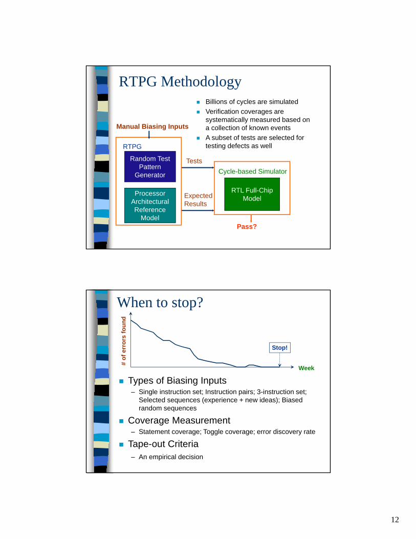
For processors - RTPGFor processor verification
RTPG – Random Test Program Generation
Basic Ideas– Symbolic execution– Biasing inputs
RTPG’s job is to ensure the instruction sequences are meaningful– Hide many details from user– Allow user to specify constraints and biases
Observability is a key issueDecide where you want and you can check the results of simulation– You need to know the expected behavior first
Logical registers may not be the same as physical registers– Register renaming depends on the implementation
Logical cache may not be the same as physical cache structure– 1 level cache vs. 3 level cache
Memory is the only “safe” observation point
Memory
μ-processorinst
ruct
ion
sequ
ence
s Safeobservationpoint
registers
cache
potentialobservation points
12
RTPG MethodologyBillions of cycles are simulatedVerification coverages are systematically measured based on a collection of known eventsA subset of tests are selected for testing defects as well
ProcessorArchitecturalReference
Model
Random TestPattern
Generator
Manual Biasing Inputs
Tests
ExpectedResults
RTPG
RTL Full-ChipModel
Cycle-based Simulator
Pass?
When to stop?
Types of Biasing Inputs– Single instruction set; Instruction pairs; 3-instruction set;
Selected sequences (experience + new ideas); Biased random sequences
Coverage Measurement– Statement coverage; Toggle coverage; error discovery rate
Tape-out Criteria– An empirical decision
Week
# of
err
ors
foun
d
Stop!

13
Recall: Pre-silicon Validation cyclesnot that we don’t try
0
1000
2000
3000
4000
5000
6000
40'9
8
43'9
8
46'9
8
49'9
8
52'9
8
03'9
9
06'9
9
09'9
9
12'9
9
15'9
9
18'9
9
21'9
9
24'9
9
27'9
9
30'9
9
33'9
9
36'9
9
39'9
9
42'9
9
45'9
9
48'9
9
51'9
9
(Millions)
Pentium 4
Full-chip
~1/4 secof real time execution
Verification crisisMore than 50% of the project budget already goes to verificationSimulation and testbench preparation time already drags the time-to-marketDesign complexity grows tremendously with the use of IP coresCost of chip re-spin is high– > $100K for ASIC– > $1M for a complex SOC

14
Easy vs. hard bugs
Engineers spend tremendous amount of time to develop the environment, building the models– Need good software environment, API, etc.
Engineers waste time to capture “easy” errors– Some automation is desperately needed
They should focus on capturing “hard” ones
Erro
rs a
ccum
ulat
ed
Week
“Hard” bugs
Automation
Divide and conquerAs design becomes extremely complex, fixing a bug become more tediousIf we start RTPG directly on the whole chip, – We spend a lot of time to
fix bugs in some units– Yet some other units
receive less attention

15
Unit level verification
A chip is usually divided into 6-7 unitsGoal: detect 95-99% of the design errors at unit level and the remaining 1-5% at the full-chip levelUni-Sim allows individual unit to be verified independently from the completion of other units
Tests
ExpectedResults
RTPG
A C++ system toemulate the I/O
behaviors of otherparts of the chip
New Tests
NewExpectedResults
Logic simulator
Unit underverification
Pass?
Constrained Random Test
Supported by SystemVerilog

16
RTL Verification Flow (ideal)
Verification plan
Verification environment construction
Covered all requirements ?
Done
Yes
No
Get RTL design and specifications
RTL Verification Flow (in reality)
Verification plan
Verification environment construction
Covered all requirements ?
Done
No
Get 1st version RTL design and specifications
Get 2nd version
Get 3rd version
Yes
update
update

17
Dynamic Simulation
Idea - Running simulation, then check correctness
It’s hard to guarantee a design is bug-free by this method
Dynamic Simulation (cont.)
To measure the quality of dynamic simulation, people check ‘coverage’◦ Line coverage / code coverage◦ Path coverage◦ FSM coverage◦ Toggle coverage◦ Functional coverage
CovergroupsAssertion coverage
Written by human
Generated by tools
18
observe
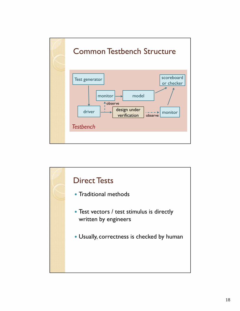
Common Testbench Structure
design under verification
model
Test generator
driver
scoreboardor checker
monitor
Testbench
monitor
observe
Direct Tests
Traditional methods
Test vectors / test stimulus is directly written by engineers
Usually, correctness is checked by human

19
Constrained Random Test Generation
Idea: generate tests randomly
However, there are several problems …◦ Some tests may be invalid or meaningless◦ Hard to generate corner cases◦ Example:
If we want to test a special adder. It takes two 8-bit inputs a and b, and its output range is [0:300]In this case, we want to add a constraint a+b ≤ 300
Test Generation (cont.)
We can use modern simulators to ◦ Solve constraints◦ Modify distributionin SystemVerilog.

20
Direct vs. RandomRandom test takes more time to start the first testRandom test takes less time to achieve high coverage
SystemVerilog
SystemVerilog is an extension to Verilog
All commercial modern simulators support SystemVerilog
It’s an object-oriented language◦ It has ‘class’, ‘inheritance’ and ‘polymorphism’
21
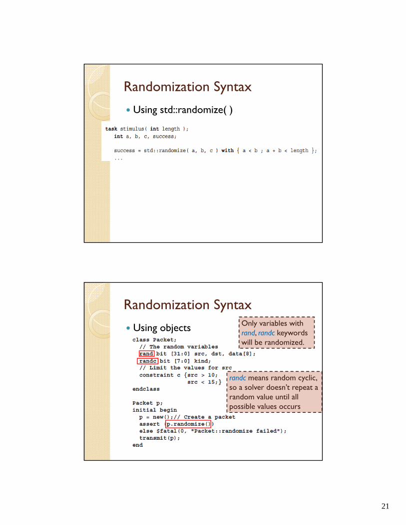
Randomization Syntax
Using std::randomize( )
Randomization Syntax
Using objects Only variables with rand, randc keywords will be randomized.
randc means random cyclic, so a solver doesn’t repeat a random value until all possible values occurs

22
Constraint Syntax
Location◦ After randomize( ) call, in with { }
Constraint Syntax (cont.)◦ Writing in class definition

23
Constraint Syntax (cont.)
operators◦ >, <, ==, >=, <=◦ !, &&, ||◦ if-else, ->◦ inside
Constraint Syntax (cont.)
Modify distribution
The distribution ratio of 0 to 7 is1, 1, 1, 8, 8, 8, 1,1
24
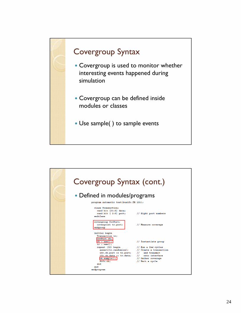
Covergroup Syntax
Covergroup is used to monitor whether interesting events happened during simulation
Covergroup can be defined inside modules or classes
Use sample( ) to sample events
Covergroup Syntax (cont.)
Defined in modules/programs

25
Covergroup Syntax (cont.)
Defined in classes
Covergroup Syntax (cont.)
Coverpoint syntax
The name of target variables// tr.kind is a 4-bit variable
Definition of interesting bins
Note: There can be many coverpoints in a covergroup.

26
Covergroup Syntax (cont.)
Transition coverage syntax
◦ This coverpoint captures if port went from 0to 1, 0 to 2, or 0 to 3.
ReferenceSystemVerilog for Verification: A Guide to Learning the Testbench Language FeaturesSystemVerilog Language Reference Manual

27
ITC 2003, Tutorial 15, Slide # 53
Trends in functional verification
Several key conceptsemployed in the industry
Slide # 54
Question
• Unit-level verification makes sense for a microprocessor design
Where the functionality of each unit is somewhat well definedThe unit-level verification environment can be re-used for the next generation
• What if we are verifying an SOC?Do we want to invest in building a unit-level verification environment for every unit and maybe we can use them once?
28
Slide # 55
Additional questions
• What is our unit-level verification strategy?
• How do we generate functional tests?• How do we check for correctness?• When we move to full chip of an SOC,
what is to be verified?What is our verification space, different from unit-level verification?It should be simpler, isn’t it?
• How to re-use verification results?
Slide # 56
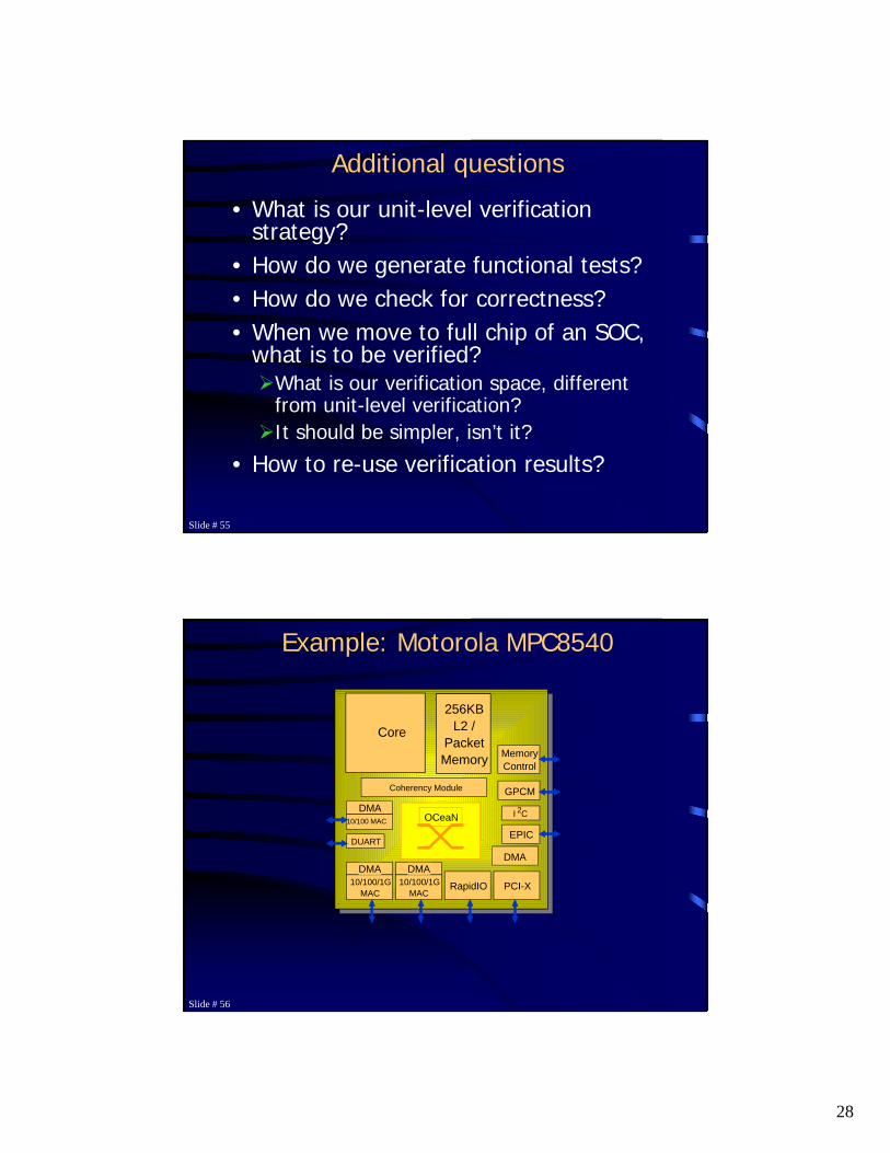
Example: Motorola MPC8540
Core
256KBL2 /
PacketMemory
PCI-XRapidIO10/100/1GMAC
DMA
MemoryControl
Coherency Module
EPIC
I 2C
DUART
GPCM
DMA
10/100/1GMAC
DMA
10/100 MAC
DMA
,,
OCeaN

29
Slide # 57
Unified Or Disparate Methodology
• A Unified methodology involves a single test generator for a project
Users do not know how tests are generatedSame test generator covers different configurations
• A Disparate methodology involves a dedicated test generator for each system configuration
End users require in-depth knowledge Software maintenance is difficult
Slide # 58
TestBench
• Dedicated testbench for each individual unit
• A testbench consists of:Drivers: Translating unit-to-unit transaction-level commands to pin signalsMonitors: Monitoring responses on the interfaces and reporting violationsBehaviors: Monitoring system operations via monitors and report system failures
• Allow maximal testbench re-use

30
Slide # 59
A Conceptual Example
A
C D
B
Slide # 60
Verification of Unit C
D-C Driver
C-D Monitor
Unit C Behavior
C
A-C Monitor
C-A Driver
C-D Monitor
Unit C Behavior
C
A-C Monitor
C-A Driver

31
Slide # 61
Verification of Unit D
D-C Driver
Unit D Behavior
D
D-B Driver
D-Ext Driver
B-D Monitor
D-Ext Monitor
C-D Monitor
Unit C Behavior
C
A-C Monitor
C-A Driver
Slide # 62
Verification of C and D w.r.t. A and B
Unit D Behavior
D
D-B Driver
D-Ext Driver
B-D Monitor
D-Ext Monitor
C-D Monitor
Unit C Behavior
C
A-C Monitor
C-A Driver
C-D Monitor
Unit C Behavior
C
A-C Monitor
C-A Driver

32
Slide # 63
Constrained Verification
Test templatewith constraints
Test generator
A design unit
Simulation
Constraint solving engine
Constrainedtestbench
Monitorresponses
Constrain the testinput space
Correctness is usually monitored through Assertions in the design
Slide # 64
A Test Template Example
Trans [2] { Master = range(0, 2)Slave = namedbias(2 => "A", 1 => "B")Dir = equalbias("read", "write")Burst = bias(1, 2)Inhibit = bias(2, 1)if (P(".Dir") eq "read") {Delay = range(0, 4)
}}
- P("Trans[*].Burst") == 0 && \P("Trans[*].Inhibit") == 1
+ P("Trans[*].Slave") eq "A"
Trans [2] { Master = range(0, 2)Slave = namedbias(2 => "A", 1 => "B")Dir = equalbias("read", "write")Burst = bias(1, 2)Inhibit = bias(2, 1)if (P(".Dir") eq "read") {Delay = range(0, 4)
}}
- P("Trans[*].Burst") == 0 && \P("Trans[*].Inhibit") == 1
+ P("Trans[*].Slave") eq "A"
Trans._count=2Trans[0].Master=0Trans[0].Slave=ATrans[0].Dir=readTrans[0].Burst=0Trans[0].Inhibit=0..
33
Slide # 65
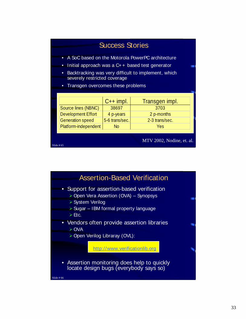
Success Stories
• A SoC based on the Motorola PowerPC architecture• Initial approach was a C++ based test generator• Backtracking was very difficult to implement, which
severely restricted coverage• Transgen overcomes these problems
C++ impl. Transgen impl.Source lines (NBNC) 38697 3703Development Effort 4 p-years 2 p-monthsGeneration speed 5-6 trans/sec. 2-3 trans/sec.Platform-independent No Yes
MTV 2002, Nodine, et. al.
Slide # 66
Assertion-Based Verification• Support for assertion-based verification
Open Vera Assertion (OVA) – SynopsysSystem VerilogSugar – IBM formal property languageEtc.
• Vendors often provide assertion librariesOVAOpen Verilog Libraray (OVL):
http://www.verificationlib.org
• Assertion monitoring does help to quickly locate design bugs (everybody says so)

34
Slide # 67
An assertion example (OVL)• //------------------------------------------------------------------
---------• //• // ASSERT_NO_OVERFLOW• //• //------------------------------------------------------------------
---------• // NAME• // ASSERT_NO_OVERFLOW - An invariant concurrent assertion to
ensure• // an expression (or variable) does not exceed• // a MAX value or reach a value <= MIN limit.• //• //------------------------------------------------------------------
---------• module assert_no_overflow (clk, reset_n, test_expr);• // synopsys template• parameter severity_level = 0;• parameter width=1;• parameter min=0;• parameter max= ((1<<width)-1);• parameter options = 0;• parameter msg="VIOLATION";• input clk, reset_n;• input [width-1:0] test_expr;
• `ifdef ASSERT_ON• `ifdef ASSERT_OVL_VERILOG• `else• `define ASSERT_OVL_VERILOG• `endif• `endif• `ifdef ASSERT_GLOBAL_RESET• `define ASSERT_RESET_SIGNAL `ASSERT_GLOBAL_RESET• `else• `define ASSERT_RESET_SIGNAL reset_n• `endif
Slide # 68
Assertion Example (OVL)• `ifdef ASSERT_OVL_PSL
• /* psl • property ASSERT_NO_OVERFLOW =• always ((`ASSERT_RESET_SIGNAL != 1'b0) ->• (never {test_expr == max;(test_expr > max) || • (test_expr <= min)}) • abort (`ASSERT_RESET_SIGNAL == 1'b0))• @(posedge clk);• assert ASSERT_NO_OVERFLOW;• */
• `endif // ASSERT_OVL_PSL
• //synopsys translate_off• `ifdef ASSERT_OVL_VERILOG
• // local paramaters used as defines• parameter OVERFLOW_START = 1'b0;• parameter OVERFLOW_CHECK = 1'b1;
• reg r_state;• initial r_state=OVERFLOW_START;
• parameter assert_name = "ASSERT_NO_OVERFLOW";
• integer error_count;• initial error_count = 0;
• `include "ovl_task.h"

35
Slide # 69
Assertion Example (OVL)• `ifdef ASSERT_INIT_MSG• initial• ovl_init_msg; // Call the User Defined Init Message Routine• `endif
• always @(posedge clk) begin• if (`ASSERT_RESET_SIGNAL != 1'b0) begin• case (r_state)• OVERFLOW_START:• if (test_expr == max) begin• r_state <= OVERFLOW_CHECK;• end• OVERFLOW_CHECK:• if (test_expr != max) begin• r_state <= OVERFLOW_START;• if (test_expr <= min || test_expr > max) begin• ovl_error("");• end• end• endcase• end• else begin• r_state <= OVERFLOW_START;• end• end // always• `endif• //synopsys translate_on• `undef ASSERT_RESET_SIGNAL
• endmodule
Slide # 70
Assertion Example (OVA)// define basic eventsbool read_setup: sel && ~enable && ~writebool read_enable: sel && enable && readbool write_setup: sel && ~enable && ~readbool write_enable: sel && enable && writebool idle: ~sel && ~enable
clock posedge clk {event read: if (read_setup) #2 read_enable;event write: if (write_setup) #1 write_enable;
}
assert read_a : check(read);assert write_a : check(write);

36
Slide # 71
Transaction-Based Verification• RapidIO design
RTL model to describe the hardwareTransaction definitions to describe the transactions allowedAssertions in place to describe design properties and to monitor simulation
• All of above are part of the design
RapidIO bus
Read(data, address)Write(data, address) Transaction
Layer of abstraction00001011010101
100010100111100100
Slide # 72
Verification Re-use
• Re-use of test templatesEspecially true in microprocessor verification
• Verification IPsBuilt-in assertion with IP coresPre-built verification environment for IPs

37
Slide # 73
Verification IP – Re-use• For an IP core, its
verification environment can be re-used as well
Assertion re-useTransaction definition re-useTestbench re-use
• IP users only need to deal with application specific transactions to develop their own testbench
Simulation engine
Hardware signals
transactions
Transaction test sequences
Applicationspecifictransaction tests
IP users
Cov
erag
e re
port