Embed Size (px)
Citation preview
7. LS-DYNA Anwenderforum, Bamberg 2008
© 2008 Copyright by DYNAmore GmbH
Simulation of Low Velocity Impact on Composite Plates with Compressive Preload
Sebastian Heimbs*, Sven Heller**, Peter Middendorf*
*EADS, Innovation Works, 81663 Munich, Germany **Universität Karlsruhe (TH), 76131 Karlsruhe, Germany
Summary: The impact behaviour of fibre-reinforced composite materials is much more complex than it is for conventional metallic structures due to a number of different failure modes on the interlaminar and intralaminar level. In most of the past research studies unloaded specimens have been used for impact tests. However, in reality it is much more likely that a composite structure is exposed to a certain stress state when it is being impacted, which can have a significant effect on the impact performance. Therefore, in this study the influence of a compressive preload on the low velocity impact behaviour of a carbon fibre-reinforced composite plate was investigated both experimentally and numerically. Besides the evaluation of the experimental findings, this paper primarily describes the finite element modelling strategy of this preloaded composite plate for impact simulations with LS-DYNA. The main topics addressed in this context are the composite material and delamination modelling as well as the implementation of the preload. The assessment of different modelling approaches, the influence of various simulation parameters and a comparison of the experimental and numerical results are documented in this paper. Keywords: Composite material, impact simulation, delamination, preloading.

7. LS-DYNA Anwenderforum, Bamberg 2008
© 2008 Copyright by DYNAmore GmbH
1 Introduction
Fibre-reinforced composite materials are known for their high weight-specific mechanical properties and are therefore used in numerous lightweight engineering applications, in particular in aircraft design. However, a constant concern for such laminates – much more than for similar metallic structures – are impact loads of foreign objects, which can cause internal material damage. This damage can significantly reduce the strength and can grow under load and may be difficult to detect. Typical impact scenarios in aircraft design range from a tool dropped on the laminate surface (high mass, low velocity), over runway debris thrown up by the tires or hail (low mass, high velocity) to bird strike during flight (high mass, high velocity).
The impact behaviour of composite laminates has been treated extensively in the technical literature. A comprehensive literature overview on this topic is given by Abrate [1]. However, nearly all studies are concerned with impact loads on unloaded composite materials. But with regard to aircraft structures, it is rather unlikely that the impacted surface is unloaded. The composite structure may be subject to compressive, tensile or shear loads in the operational environment. Therefore, knowledge of the effect of preloading on the impact behaviour of composite laminates is of significance, since the damage development can be drastically different. Only very few studies in the literature cover this topic.
Analytical investigations were performed by Sun and Chattopadhyay [2] as well as Khalili et al. [3]. They come to the conform results that under tensile preloading the contact force is increased and the contact time as well as the deflection are reduced compared to the unloaded plate. These results were confirmed by the experimental tests of Mitrevski et al. [4] on glass fibre-reinforced (GFRP) composites. Besides these GFRP laminates, most papers deal with experimental investigations of the influence of preloading on the low velocity impact behaviour of carbon fibre-reinforced composites (CFRP). And here, in particular, uniaxial and biaxial tensile preloading is investigated, as by Butcher [5], Sankar and Sun [6], Park [7], Nettles et al. [8], Herszberg et al. [9], Kelkar et al. [10], Mines et al. [11] and Whittingham et al. [12]. The results of these studies show that the tensile preload significantly affects the failure behaviour and failure modes.
The stress situation in the lower aircraft fuselage during take-off, when it is likely to be exposed to impacting stones propelled by the tires, is a compressive stress state. The impact behaviour under such compressive preloads is addressed in even fewer papers. This preloading condition is yet more complex because plate buckling becomes an issue for relatively thin composite structures. The investigations of Starnes et al. [13], Nettles and Lance [14], Robb et al. [15], Tweed et al. [16], Chiu et al. [17] and Zhang et al. [18] include such compressive preloads.
Besides pure experimental investigations on the impact behaviour of composite laminates, numerical finite element (FE) simulations play an increasingly relevant role in engineering development. Validated simulations not only allow for a detailed analysis of stress distributions and damage progression in the laminate during the impact event but also enable efficient parameter studies with respect to geometries, loading conditions or laminate configurations. For the simulation of an impact as a transient load case, FE codes based on an explicit time integration scheme are typically used, which are characterised by small time step intervals. On the other side, the preloading happens on a static basis, making implicit calculations more appropriate. Therefore, the combination of preloading and impact loading requires special numerical strategies. FE simulations of low velocity impacts on preloaded composite structures have first been addressed by Sun and Chen [19]. However, just like in the work of Tweed et al. [16] and Mines et al. [20], who used the commercial explicit code LS-DYNA, no detailed information on the preload modelling is given. Kelkar et al. [21] bring forward the argument that their static and dynamic tests led to the same results. As a consequence, they considered the impact as a static loading and combined the preloading and impact simulation in an entirely implicit calculation with the commercial software ANSYS. Zhang et al. [18] used the in-house FE package FE77 and performed a completely explicit simulation utilising dynamic relaxation for the preloading. Mikkor et al. [22] as well as Pickett et al. [23] used the commercial explicit code PAM-CRASH. Especially in the latter paper a detailed description of the preloading modelling is given, which is performed as a part of the explicit simulation by stretching the composite plate directly before the impact load.
The aim of the current paper is to develop modelling strategies for the low velocity impact simulation of CFRP plates under compressive preload with LS-DYNA with the emphasis on the laminate, delamination and preload modelling. An experimental low velocity impact test series provides the data for comparison and model validation.
7. LS-DYNA Anwenderforum, Bamberg 2008
© 2008 Copyright by DYNAmore GmbH
2 Impact Testing of Preloaded CFRP Plates
2.1 Materials and Specimen Manufacturing
The material in this study is a carbon fibre-reinforced epoxy (CF/EP) laminate with a symmetric, quasi-isotropic lay-up of 24 plies [-45°/0°/45°/90°]3s. In the unidirectional plies with the specification Cytec® 977-2-35-12K HTS-134 the carbon fibres were impregnated with an epoxy matrix. These prepreg plies were stacked according to the target fibre orientation angles and were cured to a plate in an autoclave. The resulting average cured plate thickness was 2.7 mm with a standard deviation of 0.11 mm. A diamond saw was used to cut out the final test specimens with a size of 400 mm x 150 mm. 2 mm thick tapered GFRP tabs with a width of 50 mm were bonded onto both sides of these specimens, reducing the free specimen length to 300 mm (Fig. 1). Both specimen ends were ground parallel to ensure a uniform lengthwise compressive load distribution. A total of six strain gauges were applied on each preloaded specimen, five on the upper and one on the lower surface, see Fig. 1. These strain gauges gave valuable information on the prestrain level, on the uniformity of the load distribution in length and width direction of the plate and if plate buckling occurs under the compressive preload.
Fig. 1: Dimensions of impact test specimens (in mm) and micrograph of composite laminate
2.2 Low Velocity Impact Testing
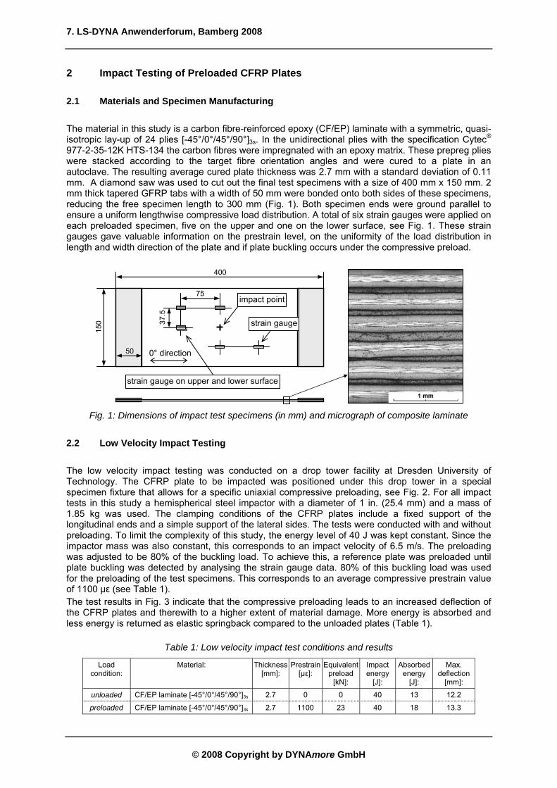
The low velocity impact testing was conducted on a drop tower facility at Dresden University of Technology. The CFRP plate to be impacted was positioned under this drop tower in a special specimen fixture that allows for a specific uniaxial compressive preloading, see Fig. 2. For all impact tests in this study a hemispherical steel impactor with a diameter of 1 in. (25.4 mm) and a mass of 1.85 kg was used. The clamping conditions of the CFRP plates include a fixed support of the longitudinal ends and a simple support of the lateral sides. The tests were conducted with and without preloading. To limit the complexity of this study, the energy level of 40 J was kept constant. Since the impactor mass was also constant, this corresponds to an impact velocity of 6.5 m/s. The preloading was adjusted to be 80% of the buckling load. To achieve this, a reference plate was preloaded until plate buckling was detected by analysing the strain gauge data. 80% of this buckling load was used for the preloading of the test specimens. This corresponds to an average compressive prestrain value of 1100 µε (see Table 1). The test results in Fig. 3 indicate that the compressive preloading leads to an increased deflection of the CFRP plates and therewith to a higher extent of material damage. More energy is absorbed and less energy is returned as elastic springback compared to the unloaded plates (Table 1).
Table 1: Low velocity impact test conditions and results
Load condition:
Material: Thickness [mm]:
Prestrain [µε]:
Equivalent preload
[kN]:
Impact energy
[J]:
Absorbed energy
[J]:
Max. deflection
[mm]:
unloaded CF/EP laminate [-45°/0°/45°/90°]3s 2.7 0 0 40 13 12.2
preloaded CF/EP laminate [-45°/0°/45°/90°]3s 2.7 1100 23 40 18 13.3
400
150
50
75
37.5
impact point
strain gauge
strain gauge on upper and lower surface
0° direction

7. LS-DYNA Anwenderforum, Bamberg 2008
© 2008 Copyright by DYNAmore GmbH
Fig. 2: Top view of impactor and specimen in test rig
0
1
2
3
4
5
6
7
8
9
0 1 2 3 4 5 6 7Time [ms]
Forc
e [k
N]
0
5
10
15
20
25
30
35
40
45
Ener
gy [J
] D
ispl
acem
ent [
mm
]
Force (unloaded)Force (preloaded)Energy (unloaded)Energy (preloaded)Displacement (unloaded)Displacement (preloaded)
Fig. 3: Experimental force, energy and displacement plots for unloaded and preloaded plates
3 Model Development
The development of the FE model for the low velocity impact simulations in LS-DYNA involves the modelling of the composite material including intralaminar failure and delamination failure, the modelling of the preload and the modelling of the impactor. These topics are addressed as follows.
3.1 Composite Material Modelling
The composite plates consist of 24 plies of unidirectional CF/EP. As the plates’ length and width dimensions are large compared to the thickness, a 2D modelling approach with shell elements is appropriate. Of the different composite material models for shell elements in LS-DYNA, the linear-elastic model MAT54 MAT_ENHANCED_COMPOSITE_DAMAGE was used. The elastic material behaviour of the individual ply is calculated based on the input of the Young’s modulus, shear modulus and Poisson’s ratio. Damage occurs as soon as one of the four criteria by Chang/Chang [24] is met:
preloading
impactor
specimen

7. LS-DYNA Anwenderforum, Bamberg 2008
© 2008 Copyright by DYNAmore GmbH
Tensile failure, fibre direction: ⎩⎨⎧<≥
−⎟⎠
⎞⎜⎝
⎛+⎟⎠
⎞⎜⎝
⎛=elasticfailure
SCXTe tf 0
01
212
212
,τ
βσ (1)
Compressive failure, fibre direction: ⎩⎨⎧<≥
−⎟⎠
⎞⎜⎝
⎛=elasticfailure
XCe cf 0
01
212
,σ (2)
Tensile failure, matrix direction: ⎩⎨⎧<≥
−⎟⎠
⎞⎜⎝
⎛+⎟⎠
⎞⎜⎝
⎛=elasticfailure
SCYTe tm 0
01
212
222
,τσ (3)
Compressive failure, matrix direction: ⎩⎨⎧<≥
−⎟⎠⎞
⎜⎝⎛+⎟⎟
⎠
⎞⎜⎜⎝
⎛−+⎟
⎠⎞
⎜⎝⎛=
elasticfailure
SCSCYC
YCSCe cm 0
011
42
212
2
22
222
,τσσ . (4)
In addition to these stress-based criteria, the user can define failure strains as well. When these failure strains DFAILx in MAT54 are used, the stress level after meeting the Chang/Chang criteria is kept at a constant level until the failure strains are reached. Then the respective layer is assigned with zero stiffness properties. Inside one shell element a number of sub-layers can be defined in thickness direction representing the laminate lay-up. In this study, each single ply was defined by one integration point with the respective ply thickness and fibre orientation angle. Once all single layers of the shell element have failed, the whole element is eroded, i.e. deleted from the calculation. The material properties used for modelling of the NCF and prepreg material are summarised in Table 2.
Underintegrated shell elements of the type Belytschko-Tsay (ELFORM=2) with the stiffness-based hourglass control (IHQ=4) were used for the modelling of the composite plate. This was justified since the hourglass energy in the final impact simulations was negligible with less that 1% of the total energy.
Table 2: Overview of CFRP elastic and failure properties used in this study
Material: ρ [g/cm³]
E11 [GPa]
E22 [GPa]
G12 [GPa]
ν12
[-] XT
[MPa]XC
[MPa]YT
[MPa]YC
[MPa]SC
[MPa] DFAILT DFAILC DFAILM DFAILS GIC [J/m²]
GIIC [J/m²]
CF/EP laminate 1.6 153 10.3 5.2 0.3 2540 1500 82 236 90 0.017 0.0135 0.1 0.03 225 640
3.2 Delamination Modelling
Interlaminar failure, i.e. a separation of two laminate layers, which is referred to as delamination, plays a significant role in low velocity impact loading of composite plates as an energy absorption mechanism and a degradation factor of the plate’s stiffness and should therefore be implemented in the simulation model. In LS-DYNA, there are two common techniques how to include delamination failure in a shell model.
One way is the utilisation of cohesive brick elements between separate layers of shell elements with an adequate material law that describes the damage progress of the laminate connection. It must be pointed out that different layers of cohesive elements may not share common nodes. Therefore, additional contact definitions have to be used for the connection of the cohesive elements in a multi-layer shell model with more than one layer of cohesive elements, making this modelling technique rather complex.
The other way, which was adopted in this study, is to use the tiebreak contact formulation CONTACT_AUTOMATIC_ONE_WAY_SURFACE_TO_SURFACE_TIEBREAK with OPTION=8. This contact allows for the simulation of crack propagation based on the cohesive zone model, implemented in LS-DYNA as a delamination contact by Borg [25]. After defined normal and shear failure stresses (NFLS, SFLS) are met, damage is a linear function of the distance of two points initially in contact. As soon as a defined critical crack opening (CCRIT) is reached, the contact is released and converted into a regular surface-to-surface contact preventing penetrations. The energy released due to normal interface failure GIC is approximated by
CCRITNFLSGIC ⋅⋅=21 . (5)

7. LS-DYNA Anwenderforum, Bamberg 2008
© 2008 Copyright by DYNAmore GmbH
This study covers a 24-ply CFRP laminate. If each ply is modelled as a separate layer of shell elements with 23 delamination contact formulations in-between, the model would be very expensive to calculate. As an alternative, different models with two, three, four and six separate layers of shell elements were generated, each shell element covering a certain number of different plies as different internal integration points. For comparison reasons, a model with just one shell element and without delamination was also generated. The mesh-dependent parameters of the delamination contact were adjusted using double cantilever beam (DCB) models. Identical parameters were used for the models with two to six layers of shell elements. Although this approach is not able to cover reality by enabling a delamination between each single ply, it is, however, a first approach to evaluate if interlaminar failure occurs at all and an additional energy absorption mechanism.
3.3 Preload Modelling
While the low velocity impact is a transient load case with material damage occurring in a short time period, the compressive preloading of the composite plate, on the other hand, happens on a rather static basis. To combine these two loadings in a single model, different numerical approaches are possible in LS-DYNA.
One way is to use the implicit LS-DYNA solver for the preloading and the explicit solver for the transient impact loading. The implicit-explicit switching functionality in LS-DYNA is straightforward and can be performed within one single input deck (CONTROL_IMPLICIT_GENERAL, parameter IMFLAG). With this technique, the implicit preloading calculation takes only a few seconds, making this method very efficient. However, the automatic delamination contact does not work properly in the implicit analysis and leads to severe instabilities. Therefore, a workaround is the utilisation of a standard tied contact for the implicit and the automatic delamination contact for the explicit calculation, using the birth and death time controls in the respective contact definitions. But since the tied contact does not transfer moments, the plate’s stiffness and buckling load are reduced. The plate buckles under significantly lower preloading conditions, making this technique inapplicable. The cohesive elements, as an alternative for delamination modelling, are also not available for implicit analyses.
The other way is to use solely the explicit LS-DYNA solver, also for the preloading. To avoid oscillations, the displacement-controlled preloading should be applied within a sufficiently long time interval, making this method less computationally efficient – though more stable. Another option to avoid oscillations is to use the dynamic relaxation feature (CONTROL_DYNAMIC_RELAXATION). Within this algorithm, nodal velocities are damped by a defined factor DRFCTR each time step until the kinetic energy falls below a specific convergence value DRTOL. Then the dynamic relaxation analysis stops and the current state becomes the initial state of the impact analysis.
In this study, the explicit solver without dynamic relaxation was used for both preloading and impact loading due to stability reasons. The displacement-controlled compressive prestress was applied with the command BOUNDARY_PRESCRIBED_MOTION within 10 ms (without provoking any noticeable oscillations), with the impact event lasting approx. 6 ms until springback. With respect to a slightly decreasing time step size, this corresponds to half of the total computational time ascribed to the preloading and the other half to the impact load.
The other boundary conditions in the model were defined corresponding to the impact test rig, with fully constrained nodes at the longitudinal ends of the specimen and simply supported nodes at the lateral ends.
3.4 Impactor Modelling
The impactor was modelled as a spherical rigid body with conventional shell elements and the LS-DYNA material model MAT_RIGID as well as a defined initial velocity. Another alternative would be the modelling of the impactor as an idealised spherical contact entity (CONTACT_ENTITY with GEOTYP=2 and PART_INERTIA to cover the impactor mass) without a user-defined mesh. However, in this study this led to a significantly higher computational cost, and was therefore not applied.

7. LS-DYNA Anwenderforum, Bamberg 2008
© 2008 Copyright by DYNAmore GmbH
4 Simulation Results
4.1 Comparison between Simulation and Experiment
In this section the simulation results are presented and compared with the experimental data. Since numerous simulation parameters have a significant influence on the numerical results, one reference model is treated first, the influence of the single parameters (mesh size, number of shell element layers etc.) is discussed later. This reference model consists of three layers of shell elements with two delamination tiebreak contacts in-between and an element length of 3 mm (Fig. 4).
after 3 ms
Fig. 4: Reference model for low velocity impact simulations on preloaded composite plate
For a comparison between experimental and numerical results, the following data were evaluated:
• Impact contact force:
While the contact force in the experiment was recorded directly by the strain gauge-based load cell, the RCFORC output file in LS-DYNA was evaluated to obtain the resultant interface forces. The results for the unloaded and preloaded case are shown in Fig. 5. The correlation between experiment and simulation is acceptable in both cases. In the beginning, the behaviour is characterised by an oscillation of the plate after first contact with the impactor, which is represented correctly by the simulation model. When the plate swings back upwards the contact force increases steeply. The further drops in the force plot result from oscillations and material damage. Despite some deviations in the curve peak values, the overall contact time matches again very satisfactorily.
Force plot - unloaded
0
1
2
3
4
5
6
7
8
9
0 1 2 3 4 5 6 7time [ms]
forc
e [k
N]
ExperimentLS-DYNA simulation
Force plot - preloaded
0
1
2
3
4
5
6
7
8
9
0 1 2 3 4 5 6 7time [ms]
forc
e [k
N]
ExperimentLS-DYNA simulation
Fig. 5: Contact force plot in experiment and simulation for unloaded and preloaded plates

7. LS-DYNA Anwenderforum, Bamberg 2008
© 2008 Copyright by DYNAmore GmbH
• Energy plot:
In both experiment and simulation the inverted kinetic energy was plotted against the time (in LS-DYNA: MATSUM kinetic energy). The results are shown in Fig. 6. For the unloaded and preloaded case the experimental and numerical curves match with a high degree of accuracy. Also the final values of the absorbed energy are in good correlation. Only in the simulation with preloading some unphysical behaviour occurs resulting from the impactor contact leading to a localised minimum at the end of the energy curve.
Energy plot - unloaded
0
10
20
30
40
0 1 2 3 4 5 6 7time [ms]
ener
gy [J
]
ExperimentLS-DYNA simulation
Energy plot - preloaded
0
10
20
30
40
0 1 2 3 4 5 6 7time [ms]
ener
gy [J
]
ExperimentLS-DYNA simulation
Fig. 6: Energy plot in experiment and simulation for unloaded and preloaded plates
• Interlaminar failure (delamination):
The extent of delaminations in the test specimens was evaluated with ultrasonic C-scan inspections. In the simulation model the additional interface force file INTFOR was written out, requested by a respective command in the LS-DYNA execution line (s=INTFOR). This file includes the contact gap data, which can be used for the visualisation of the delamination contact in LS-Prepost (Fcomp Nodal Contact gap). Once the delamination contact fails completely and CCRIT is reached, the respective nodal value changes from 1 to 0, which can be visualised in a two-coloured fringe plot. In the experiment, the delaminated area for the unloaded and preloaded case is almost equivalent or at most marginally higher for the plate with compressive preload. The diameter is approx. 25 mm. In the reference simulation model two tiebreak contact interfaces were used to separate three shell element layers. The visualisation of the delaminated area as described above leads also to a diameter of 25-30 mm. However, is has to be kept in mind that the comparability of the two illustrations in Fig. 7 is limited, because the model does not cover physical reality. Although the area might be similar from the top view, the real delaminations in the C-scan image are built up from numerous dumbbell-shaped delaminations oriented with respect to the individual fibre angle. The simulation results just indicate that interlaminar failure occurs and give a rough estimation of the propagation.
C-scan - preloaded
LS-Prepost (nodal contact gap) - preloaded
Fig. 7: Extent of delamination in experiment and simulation for preloaded plate
tiebreak interface 1
tiebreak interface 2
contact release = delamination

7. LS-DYNA Anwenderforum, Bamberg 2008
© 2008 Copyright by DYNAmore GmbH
• Intralaminar failure (fibre/matrix failure):
The intralaminar fibre and matrix damage could not be evaluated in the test specimens but could only be analysed in the LS-DYNA simulation results by plotting the MAT54 history variables (HV). These variables are set from 1 to 0 if failure occurs in fibre tensile mode (HV1), fibre compressive mode (HV2), matrix tensile mode (HV3) or matrix compressive mode (HV4). The simulation results of the reference model showed that the only intralaminar failure occurs in matrix tensile mode (HV3). The two-coloured fringe plot of this history variable for the individual integration points across the thickness of the 24-ply laminate is shown in Fig. 8. Three stacks with eight layers can be seen, each stack representing one shell element and each layer representing one integration point across the shell’s thickness. Damage starts from the bottom plies on the opposite side of the impact. This is the tensile side under plate bending and since the matrix tensile strength has the lowest value (see Table 2), failure occurs in matrix tensile mode. This phenomenon with higher damage in the bottom plies can both be observed for the global structure as well as for each single shell element. The extent of intralaminar damage for the preloaded model is slightly higher than for the unloaded plate.
-45° 0°
45° 90° -45° 0°
45° 90°
-45° 0°
45° 90° 90° 45° 0°
-45°
90° 45° 0°
-45° 90° 45° 0°
-45°
MAT54 HV3 - preloaded
Fig. 8: Extent of matrix tensile failure in preloaded plate
4.2 Influence of Element Size
Since the element size is known to have an influence on simulation results, a parameter study was carried out, investigating element lengths of 1.5 mm, 2 mm, 3 mm, 4.7 mm, 6 mm and 8 mm (Fig. 9). This study covered both models with and without a delamination contact. The results of this study showed a strong mesh dependency. This is because both the composite material failure behaviour of MAT54 and also the delamination contact are influenced by the element size, and therefore the absorbed energy varies with the element length (Fig. 10). The parameters of the delamination contact need to be adjusted for each mesh size to obtain consistent results.
failure at integration point

7. LS-DYNA Anwenderforum, Bamberg 2008
© 2008 Copyright by DYNAmore GmbH
6 mm
3 mm
2 mm
1.5 mm
Fig. 9: Overview of different mesh sizes for composite plate with element lengths from 1.5 to 6 mm
Influence of element size
0
10
20
30
40
0 1 2 3 4 5 6 7
time [ms]
ener
gy [J
]
6 mm3 mm2 mm1.5 mm
Fig. 10: Influence of element size on energy plot (here: stacked shell model with 1 delamination contact)
4.3 Influence of Number of Shell Layers
To evaluate the influence of the number of shell element layers in the stacked shell model, or in other words the number of delamination contact interfaces in-between, models with two, three, four and six layers of shell elements across the thickness were generated with tiebreak contact definitions in-between. A model with just one layer of shell elements without delamination was also compared (Fig. 11). The corresponding energy plots from the impact simulations in Fig. 12 show a strong influence of the number of shell layers. In the model without delamination contact, the absorbed energy has the lowest value. This is because no interlaminar failure can occur in this model. Instead of that, intralaminar failure in fibre tension mode occurs in this model, which does not happen in the other models with delamination contact definitions. In general, the more delamination contact interfaces are used, the more the bending stiffness of the plate is reduced even if no delamination occurs. In other words, the bending stiffness of a stacked shell model is lower than the one of a layered shell model. This relation could be verified for different mesh sizes by means of bending simulations of a cantilever beam. The less the bending stiffness, the higher is the deflection and the material damage. In this context, the one-shell-model without delamination contact showed the highest stiffness and the lowest deflection. Therefore, an increase of the number of shell elements and delamination contacts does not necessarily bring the model closer to reality, when its stiffness behaviour is degraded in such a way.

7. LS-DYNA Anwenderforum, Bamberg 2008
© 2008 Copyright by DYNAmore GmbH
1 shell element 2 shell elements 3 shell elements
4 shell elements 6 shell elements
Fig. 11: Overview of different number of shell element layers for the composite laminate modelling
Influence of shell layers
0
10
20
30
40
0 1 2 3 4 5 6 7
time [ms]
ener
gy [J
]
3 shell elements2 shell elements1 shell element
Fig. 12: Influence of number of shell layers on energy plot (here: element size 3 mm)
4.4 Influence of Contact Penalty Stiffness
A third major influence factor on the simulation results was found out to be the contact penalty stiffness in the segment-based automatic surface-to-surface contact between the two different materials of impactor and composite plate (SOFT=2). The contact stiffness in this case with SOFT=2 is calculated from the nodal mass divided by the square of the time step size with a scale factor to ensure stability, making it independent of the material constants and therefore suited for the contact of two different materials. The scale factor is defined by the parameter SLSFAC in CONTROL_CONTACT and by SFS in contact card 3, both scale factors are multiplied. The default value of SFS=1 had to be reduced, otherwise the elements in contact failed and were eroded so that the impactor penetrated through the plate (Fig. 13). The adjustment of the contact stiffness is a well-known issue especially for different materials and dissimilar mesh sizes [26]. For the delamination tiebreak contact the default soft constraint option SOFT=0 was used without additional scaling of the contact stiffness. In this case the contact stiffness is calculated from the size of the contact segment and its material properties.
Influence of impactor contact stiffness scale factor
0
10
20
30
40
0 1 2 3 4 5 6 7
time [ms]
ener
gy [J
]
SFS=1SFS=0.1SFS=0.01SFS=0.001SFS=0.0001
Fig. 13: Influence of contact stiffness scaling on energy plot (here: element size 3 mm, SOFT=2)

7. LS-DYNA Anwenderforum, Bamberg 2008
© 2008 Copyright by DYNAmore GmbH
4.5 Influence of other Parameters
Besides the factors described before, there are a number of further parameters influencing the simulation results, which have to be adjusted with care. An overview on the major parameters is given as follows:
• Element size
• Number of shell element layers with tiebreak contacts in-between
• Contact penalty stiffness for impactor contact
• Damping (DAMPING_PART_STIFFNESS, the utilisation reduces the dissipated energy)
• Element type (more energy is dissipated if fully integrated shell elements (ELFORM=16) are used instead of the underintegrated Belytschko-Tsay Elements with ELFORM=2)
• Impact position (impacting a node instead of the middle of a shell element may facilitate hourglass effects)
• Material model (in this study MAT54 was used, but MAT55, MAT58 or MAT59 with a different damage treatment are also feasible)
• Material model properties (stiffness, strength and failure strains DFAILx as well as the shear interaction control parameters ALPH and BETA significantly influence the results)
• Delamination contact parameters in tiebreak contact card 4: NFLS, SFLS and CCRIT.
5 Conclusions
In this study, the low velocity impact behaviour of laminated carbon fibre/epoxy plates with and without compressive preloading was investigated. The experimental test series showed an increased deflection and energy absorption for the preloaded composite plates, although the effect was not exceptionally pronounced because of rather moderate preloading conditions due to buckling limitations. Nondestructive inspections showed a large extent of delaminations occurring between individual plies, being an important energy absorption mechanism. The aim of this paper was to assess modelling methodologies in the explicit finite element software LS-DYNA to simulate the physical behaviour of the preloaded composite plate under low velocity impact loading. Different approaches for composite material modelling, delamination modelling and preloading modelling were evaluated. In this study, the composite material model MAT54 and the delamination tiebreak contact were adopted. The preloading was performed on an explicit basis, which may not be the most efficient but in this case the most stable technique. The implicit solver, which is able to reduce the computational time significantly, did not work properly with the delamination contact or alternatively with cohesive elements. The final simulation results showed a good correlation to the experimental data in terms of force and energy plots or the evaluated interlaminar and intralaminar damage. The effect of the compressive preloading with increased energy absorption could be observed in the simulation as well. However, these numerical results proved to be strongly influenced by simulation parameters, in particular the element size, the number of shell element layers and the contact stiffness scale factors. This study showed that delamination modelling is crucial for impact simulations and delamination contacts should be included in a shell model, leading to a stacked shell modelling approach. Neglecting delaminations in a one-shell-model leads to unrealistically increased intralaminar fibre/matrix damage behaviour. However, on the other side, the more delamination contact interfaces are used, the more the plate’s bending stiffness is reduced. The reference model in this study consisted of two delamination contact definitions and led to satisfactory results.

7. LS-DYNA Anwenderforum, Bamberg 2008
© 2008 Copyright by DYNAmore GmbH
6 References
[1] Abrate, S.: Impact on Composite Structures. Cambridge University Press, 1998. [2] Sun, C.T.; Chattopadhyay, S.: Dynamic Response of Anisotropic Laminated Plates under Initial Stress to
Impact of a Mass. J Appl Mech, Vol. 42, 1975, pp. 693-698. [3] Khalili, S.M.R.; Mittal, R.K.; Mohammadpanah, N.: Analysis of Fiber Reinforced Composite Plates
Subjected to Transverse Impact in the Presence of Initial Stresses. Compos Struct, Vol. 77, 2007, pp. 263-268.
[4] Mitrevski, T.; Marshall, I.H.; Thomson, R.S.; Jones, R.: Low-Velocity Impacts on Preloaded GFRP Specimens with Various Impactor Shapes. Compos Struct, Vol. 76, 2006, pp. 209-217.
[5] Butcher, B.R.: The Impact Resistance of Unidirectional CFRP under Tensile Stress. Fibre Sci Technol, Vol. 12, 1979, pp. 295-326.
[6] Sankar, B.V.; Sun, C.T.: Low-Velocity Impact Damage in Graphite-Epoxy Laminates Subjected to Tensile Initial Stresses. AIAA J, Vol. 24, 1986, pp. 470-471.
[7] Park, N.: The Impact Response of Composites under Stress. Proceedings IMechE, Fibre Reinforced Composites, March 27-29, 1990, pp. 137-143.
[8] Nettles, A.; Daniel, V.; Branscomb, C.: The Effects of Tensile Preloads on the Impact Response of Carbon/Epoxy Laminates. 40th Int. SAMPE Symposium, Anaheim, 1995, pp. 1019-1025.
[9] Herszberg, I.; Weller, T.; Leong, K.; Bannister, M.K.: The Residual Tensile Strength of Stitched and Unstitched Carbon/Epoxy Laminates Impacted under Tensile Load. Proceedings of the First Australasian Congress on Applied Mechanics, Melbourne, Australia, 1996, pp. 309-314.
[10] Kelkar, A.D.; Sankar, J.; Grace, C.: Behavior of Tensile Preloaded Composites Subjected to Low-Velocity Impact Loads. ASME Recent Advances in Solids/Structures and Application of Metallic Materials, PVP-Vol. 369, 1997, pp. 39-46.
[11] Mines, R.A.W.; Li, Q.M.; Birch, R.S.: Static Behaviour of Transversely Loaded CFRP Laminate Panels Subject to In-Plane Tension. Strain, Vol. 36, 2000, pp. 71-80.
[12] Whittingham, B.; Marshall, I.; Mitrevski, T.; Jones, R.: The Response of Composite Structures with Pre-Stress Subject to Low Velocity Impact Damage. Compos Struct, Vol. 66, 2004, pp. 685-698.
[13] Starnes, J.H.; Rhodes, M.D.; Williams, J.G.: Effect of Impact Damage and Holes on the Compressive Strength of a Graphite/Epoxy Laminate. In: R. B. Pipes (ed.) Nondestructive Evaluation and Flaw Criticality for Composite Materials, ASTM STP 696, 1979, pp. 145-171.
[14] Nettles, A.T.; Lance, D.G.: The Effects of Compressive Preloads on the Compression-After-Impact Strength of Carbon/Epoxy. NASA Technical Paper 3303, 1992.
[15] Robb, M.D.; Arnold, W.S.; Marshall, I.H.: The Damage Tolerance of GRP Laminates under Biaxial Prestress. Compos Struct, Vol. 32, 1995, pp. 141-149.
[16] Tweed, J.H.; Lee, R.J.; Dyson, R.J.; Hancox, N.L.; McCarthy, J.C.: Impact Performance of Stressed Composites. Proceedings of the 7th European Conference on Composite Materials, ECCM-7, London, UK, 1996, pp. 111-116.
[17] Chiu, S.T.; Liou, Y.Y.; Chang, Y.C.; Ong, C.I.: Low Velocity Impact Behavior of Prestressed Composite Laminates. Mater Chem Phys, Vol. 47, 1997, pp. 268-272.
[18] Zhang, Z.; Davies, G.A.O.; Hitchings, D.: Impact Damage with Compressive Preload and Post-Impact Compression of Carbon Composite Plates. Int J Impact Eng, Vol. 22, 1999, pp. 485-509.
[19] Sun, C.T.; Chen, J.K.: On the Impact of Initially Stressed Composite Laminates. J Compos Mater, Vol. 19, 1985, pp. 490-504.
[20] Mines, R.A.W.; Li, Q.M.; Birch, R.S.; Rigby, R; Al-Khalil, M.; Tanner, A.: Static Behaviour of Pre-Stressed Polymer Composite Sandwich Beams. In: E. E. Gdoutos (ed) Recent Advances in Experimental Mechanics, Springer Netherlands, 2004, pp. 671-682.
[21] Kelkar, A.D.; Sankar, J.; Rajeev, K.; Aschenbrenner, R.; Schoeppner, G.: Analysis of Tensile Preloaded Composites Subjected to Low-Velocity Impact Loads. 39th AIAA/ASME/ASCE/AHS/ ASC Structures, Structural Dynamics and Materials Conf., Long Beach, 1998, pp. 1978-1987.
[22] Mikkor, K.M.; Thomson, R.S.; Herszberg, I.; Weller, T.; Mouritz, A.P.: Finite Element Modelling of Impact on Preloaded Composite Panels. Compos Struct, Vol. 75, 2006, pp. 501-513.
[23] Pickett, A.K.; Fouinneteau, M.R.C., Middendorf, P.: Test and Modelling of Impact on Pre-Loaded Composite Panels. Submitted for publication, 2008.
[24] Chang, F.K.; Chang, K.Y.: A Progressive Damage Model for Laminated Composites Containing Stress Concentrations. Journal of Composite Materials, Vol. 21, 1987, pp. 834-855.
[25] Borg, R.: Simulation of Delamination Initiation and Growth in Fiber Composite Laminates. PhD Thesis, Linköpings Universitet, Sweden, 2002.
[26] Bala, S.: Contact Modelling in LS-DYNA, Part 2 – Contact Parameters: Default and Recommended Values. LSTC, 2001.