Embed Size (px)
Citation preview
Chemical Engineering Journal 234 (2013) 247–255
Contents lists available at ScienceDirect
Chemical Engineering Journal
journal homepage: www.elsevier .com/locate /cej
Simulation and experimental investigation of planar micromixers withshort-mixing-length
1385-8947/$ - see front matter � 2013 Elsevier B.V. All rights reserved.http://dx.doi.org/10.1016/j.cej.2013.08.067
⇑ Corresponding author at: Shahid Beheshti University, Laser and PlasmaInstitute, 1983963113 Tehran, Iran. Tel.: +98 02129904254.
E-mail address: [email protected] (H. Latifi).
Mohammad Sadegh Cheri a,b, Hamid Latifi a,b,⇑, Mohammadreza Salehi Moghaddam a,Hamidreza Shahraki a
a Shahid Beheshti University, Laser and Plasma Institute, 1983963113 Tehran, Iranb Shahid Beheshti University, Department of Physics, 1983963113 Tehran, Iran
h i g h l i g h t s
� Numerical (40 simulations) and experimental analysis of eight planer micromixers.� Finding, analysis, fabrication and characterization of optimum micromixer.� The optimum micromixer has 0.89 mixing efficiency at the 1.18 mm from the origin.� The study of the chamber and obstacle effect on the mixing efficiency and pressure drop.
a r t i c l e i n f o
Article history:Received 27 May 2013Received in revised form 22 July 2013Accepted 14 August 2013Available online 29 August 2013
Keywords:MicromixerMixing efficiencyPressure drop(3D) Navier–Stokes equationsNumerical analysis (CFD)Fabrication
a b s t r a c t
Mixing laminar flows in short lengths is an important issue in chemical, biochemical and medical reac-tions. This work presents a numerical and experimental investigation on planar micromixers for obtain-ing an optimum micromixer with short mixing length. The numerical investigation of eight planarmicromixers with two different chambers and four obstacle geometries is carried out by using threedimensional (3D) Navier–Stokes equations at the range of 0.1–40 of the Reynolds (Re) number. In total,40 simulations (eight micromixers at five Re numbers) were done and the optimum micromixer wasobtained by the analysis of the simulation data. The optimum micromixer has 0.89 and 0.99 mixing effi-ciency at Re = 0.1 and 40 respectively at the short distance of 1.18 mm from the origin. In addition, theeffect of the chamber and obstacle geometry on mixing efficiency and pressure drop at the range of0.1–40 of Re have been investigated. The results show that the chamber geometry manifests itself at alow Re number and obstacle geometry is significant at a high Re for mixing efficiency and pressure drop.The optimum micromixer was fabricated, tested and compared with the simulation results and both ofthem show a similar behavior in the mixing process.
� 2013 Elsevier B.V. All rights reserved.
1. Introduction
The unique advantages of microfluidics systems such as fastanalysis time, small samples consumption, high throughput, porta-bility and reproducibility have led to the rapid development of Lab-On a Chip (LOC) and micrototal analysis systems (lTAS) [1–2].
In most chemical, biological and medical applications such asfast and homogenous chemical reactions (crystallization, extrac-tion, polymerization and synthesis), DNA assay (separation,hybridization and sequencing), cell lysis, biological screening andmedical drug delivery, the performance of LOC and (lTAS) aredetermined by mixing efficiency. Therefore, among microfluidics
devices, micromixers are one of the most important microdevicesin LOC and lTAS and have been developed to obtain rapid and effi-cient mixing of samples [3,4].
Due to laminar flow regime in microfluidics systems, the domi-nant mixing mechanism is molecular diffusion which is a very slowprocess (Fick’s second law) [5]. Therefore, molecular diffusionincreases the time and length of the mixing process which is notcompatible with miniaturization in microfluidics systems. In orderto overcome this limitation, one effective solution for enhancing themixing performance is to increase the interfacial area betweendifferent liquids to reduce diffusion distance (Fick’s first law). Dif-ferent micromixers are presented in the literature and dependingon the mixing mechanism they can be categorized as active andpassive micromixers [6]. Active micromixers use external field orenergy such as, electro and magneto hydrodynamic [7,8], ultrasonic[9], electrokinetic [10] dielectrophoretic, pressure and thermal
248 M. Sadegh Cheri et al. / Chemical Engineering Journal 234 (2013) 247–255
distribution [11–13] to improve the mixing process. Although ac-tive micromixers have a good mixing performance at small dis-tances, they have such drawbacks as high consumption of energy,complexity of structure and their being difficult to manufactureand integrate with other microfluidics components. On the otherhand, passive micromixers do not need any external source andare usually fabricated and integrated more easily with LOC technol-ogy than are active micromixers [6]. Therefore, researchers preferto design and optimize passive micromixers [14–16].
Lamination and chaotic advection are two main mechanismswhich are employed in passive micromixers for enhancing themixing process. In lamination mechanism, the fluid is split intoseveral laminar fluids and then recombined in order to increasethe interfacial area (increasing the molecular diffusion) betweenthe fluids [17,18]. Branebjerg et al. [19] have presented the firstSplit and Recombine (SAR) micromixer using this concept. In cha-otic mechanism, the mixing is based on the creation of the trans-verse motion of flow with stretching, folding and breaking up thefluid in the cross-section of the channel. Chaotic mechanism canbe achieved by different shapes of the channel. Hossain et al.[20] have evaluated the mixing performance in three channel de-signs including zigzag, square-wave and curved. Stroock et al.[21] have used staggered herringbone patterns on the surface ofthe channel to achieve an efficient mixing. Embedded obstacle in-side the microchannel is another chaotic mechanism for enhancingthe mixing process. Fang et al. [22] have presented a chaoticmicromixer with oblique barriers on the microchannel’s wallsand have investigated the period of the mixing unit, as a crucialparameter in improving mixing. They have achieved a good mixingafter 28-period mixing unit. Wang et al. [23] have optimized thelayout of obstacles in microchannels in order to enhance mixing.Chung et al. [24] have designed a simple planar baffled micromixerwith a short mixing distance for synthesis of nanoparticles.
In this paper, the mixing performance and pressure drop ofeight micromixers, with the combination of two different cham-bers and four different obstacles are investigated for the purpose
Fig. 1. The design of planar micromixer (a) Hexagonal chamb
of comparing mixing performance and pressure drop in order toobtain an optimum design. An optimized design is selected andfabricated by a soft lithography method and is compared withthe experimental results. Section 2 considers the design and simu-lation results of eight planar micromixers and in Section 3 the fab-rication and test of the optimum design micromixer is presentedand compared with the simulation results.
2. Micromixer design and numerical investigation
2.1. Micromixer design
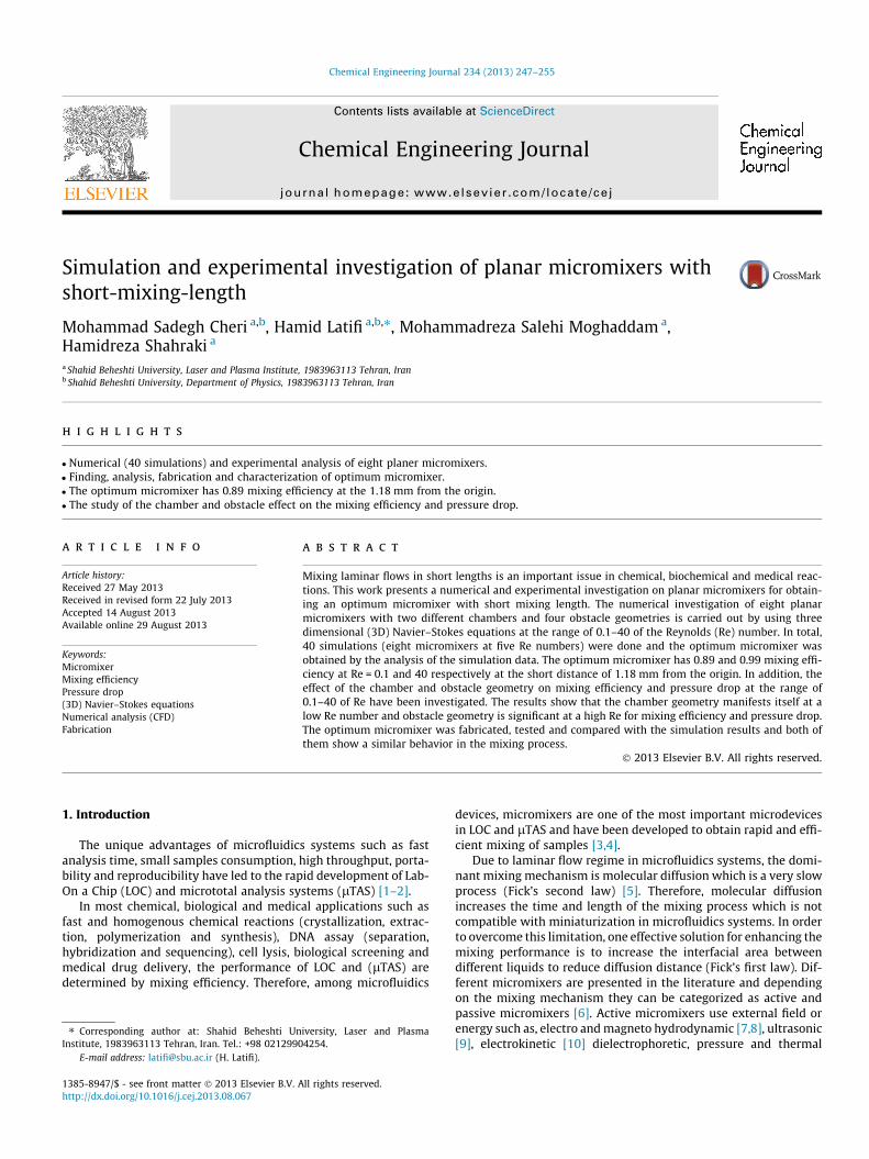
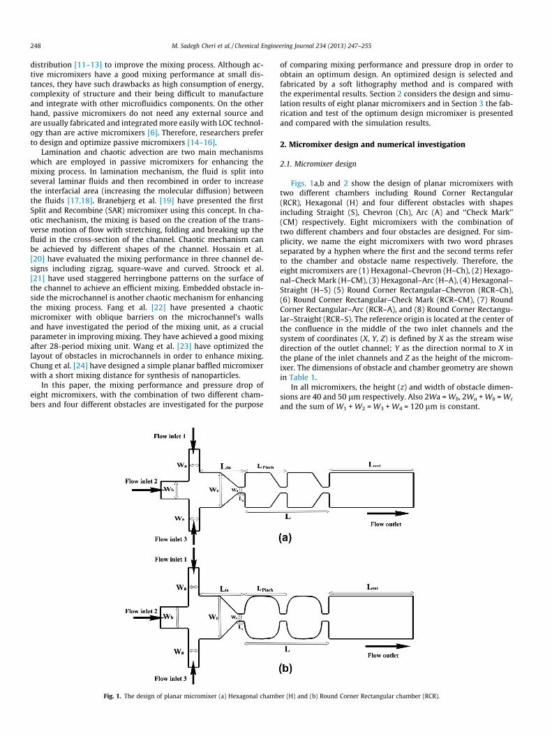
Figs. 1a,b and 2 show the design of planar micromixers withtwo different chambers including Round Corner Rectangular(RCR), Hexagonal (H) and four different obstacles with shapesincluding Straight (S), Chevron (Ch), Arc (A) and ‘‘Check Mark’’(CM) respectively. Eight micromixers with the combination oftwo different chambers and four obstacles are designed. For sim-plicity, we name the eight micromixers with two word phrasesseparated by a hyphen where the first and the second terms referto the chamber and obstacle name respectively. Therefore, theeight micromixers are (1) Hexagonal–Chevron (H–Ch), (2) Hexago-nal–Check Mark (H–CM), (3) Hexagonal–Arc (H–A), (4) Hexagonal–Straight (H–S) (5) Round Corner Rectangular–Chevron (RCR–Ch),(6) Round Corner Rectangular–Check Mark (RCR–CM), (7) RoundCorner Rectangular–Arc (RCR–A), and (8) Round Corner Rectangu-lar–Straight (RCR–S). The reference origin is located at the center ofthe confluence in the middle of the two inlet channels and thesystem of coordinates (X, Y, Z) is defined by X as the stream wisedirection of the outlet channel; Y as the direction normal to X inthe plane of the inlet channels and Z as the height of the microm-ixer. The dimensions of obstacle and chamber geometry are shownin Table 1.
In all micromixers, the height (z) and width of obstacle dimen-sions are 40 and 50 lm respectively. Also 2Wa = Wb, 2Wa + Wb = Wc
and the sum of W1 + W2 = W3 + W4 = 120 lm is constant.
er (H) and (b) Round Corner Rectangular chamber (RCR).
M. Sadegh Cheri et al. / Chemical Engineering Journal 234 (2013) 247–255 249
2.2. Numerical method
Finite-element method (FEM) based solver is employed in orderto solve the governing equations in fluids inside the microchannel.These equations include continuity equation (Eq. (1)), three-dimensional (3D) Navier–Stokes equation (Eq. (2)) and speciesconvection–diffusion equation (Eq. (3)) in order to obtain the con-centration and the degree of mixing as follows:
r � V ¼ 0 ð1Þ
q@V@tþ qV � rV ¼ �rpþ lr2V ð2Þ
@C@tþ V � rC ¼ DrC ð3Þ
where V, q, p, l, C and D, denote velocity vector, density, pressure,viscosity, species concentration and diffusion coefficient of the spe-cies respectively. Due to its negligible effect on simulation results,body force is not shown in Eq. (2). The Eqs. (1)–(3) were solved withthe following boundary conditions. Ethanol enters at the flow inlets1, 3 (molar concentrations equal to 100) and water enters at theflow inlet 2 (molar concentrations equal to 0) with average veloci-ties (V1, V2, V3) at inlets 1, 2 and 3. The average velocities (mm/s) are(1.6, 0.8, 1.6), (16.8, 8.3, 16.8), (84.1, 41.7, 84.1), (167.9, 83.4, 167.9)and (668.9, 332, 668.9) for Re numbers 0.1, 1, 5, 10 and 40 respec-tively. Zero static pressure was specified at the flow outlet. Theproperties of water and ethanol at 20 �C are shown in Table 2.
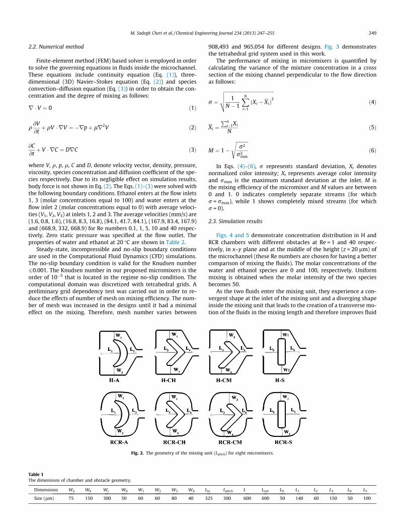
Steady-state, incompressible and no-slip boundary conditionsare used in the Computational Fluid Dynamics (CFD) simulations.The no-slip boundary condition is valid for the Knudsen number60.001. The Knudsen number in our proposed micromixers is theorder of 10�5 that is located in the regime no-slip condition. Thecomputational domain was discretized with tetrahedral grids. Apreliminary grid dependency test was carried out in order to re-duce the effects of number of mesh on mixing efficiency. The num-ber of mesh was increased in the designs until it had a minimaleffect on the mixing. Therefore, mesh number varies between
Fig. 2. The geometry of the mixing u
Table 1The dimensions of chamber and obstacle geometry.
Dimensions Wa Wb Wc Wd W1 W2 W3 W4 L
Size (lm) 75 150 300 50 60 60 80 40 3
908,493 and 965,054 for different designs. Fig. 3 demonstratesthe tetrahedral grid system used in this work.
The performance of mixing in micromixers is quantified bycalculating the variance of the mixture concentration in a crosssection of the mixing channel perpendicular to the flow directionas follows:
r ¼
ffiffiffiffiffiffiffiffiffiffiffiffiffiffiffiffiffiffiffiffiffiffiffiffiffiffiffiffiffiffiffiffiffiffiffiffiffiffiffiffiffiffi1
N � 1
XN
i¼1
ðXi � XiÞ2
vuut ð4Þ
Xi ¼Pn
i¼1Xi
Nð5Þ
M ¼ 1�
ffiffiffiffiffiffiffiffiffiffir2
r2max
sð6Þ
In Eqs. (4)–(6), r represents standard deviation, Xi denotesnormalized color intensity; Xi represents average color intensityand rmax is the maximum standard deviation at the inlet. M isthe mixing efficiency of the micromixer and M values are between0 and 1. 0 indicates completely separate streams (for whichr = rmax), while 1 shows completely mixed streams (for whichr = 0).
2.3. Simulation results
Figs. 4 and 5 demonstrate concentration distribution in H andRCR chambers with different obstacles at Re = 1 and 40 respec-tively, in x–y plane and at the middle of the height (z = 20 lm) ofthe microchannel (these Re numbers are chosen for having a bettercomparison of mixing the fluids). The molar concentrations of thewater and ethanol species are 0 and 100, respectively. Uniformmixing is obtained when the molar intensity of the two speciesbecomes 50.
As the two fluids enter the mixing unit, they experience a con-vergent shape at the inlet of the mixing unit and a diverging shapeinside the mixing unit that leads to the creation of a transverse mo-tion of the fluids in the mixing length and therefore improves fluid
nit (Lpitch) for eight micromixers.
in Lpitch L Lout L0 L1 L2 L3 L4 L5
25 300 600 600 50 140 60 150 50 100
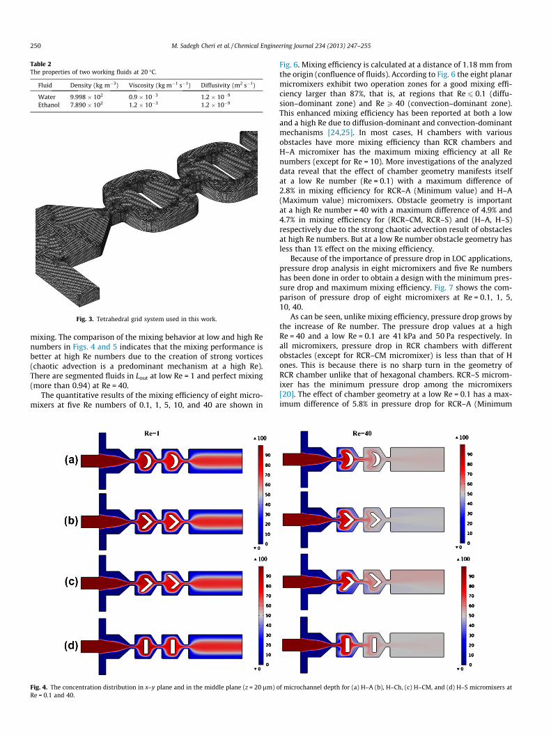
Table 2The properties of two working fluids at 20 �C.
Fluid Density (kg m�3) Viscosity (kg m�1 s�1) Diffusivity (m2 s�1)
Water 9.998 � 102 0.9 � 10�3 1.2 � 10�9
Ethanol 7.890 � 102 1.2 � 10�3 1.2 � 10�9
Fig. 3. Tetrahedral grid system used in this work.
250 M. Sadegh Cheri et al. / Chemical Engineering Journal 234 (2013) 247–255
mixing. The comparison of the mixing behavior at low and high Renumbers in Figs. 4 and 5 indicates that the mixing performance isbetter at high Re numbers due to the creation of strong vortices(chaotic advection is a predominant mechanism at a high Re).There are segmented fluids in Lout at low Re = 1 and perfect mixing(more than 0.94) at Re = 40.
The quantitative results of the mixing efficiency of eight micro-mixers at five Re numbers of 0.1, 1, 5, 10, and 40 are shown in
Fig. 4. The concentration distribution in x–y plane and in the middle plane (z = 20 lm) oRe = 0.1 and 40.
Fig. 6. Mixing efficiency is calculated at a distance of 1.18 mm fromthe origin (confluence of fluids). According to Fig. 6 the eight planarmicromixers exhibit two operation zones for a good mixing effi-ciency larger than 87%, that is, at regions that Re 6 0.1 (diffu-sion–dominant zone) and Re P 40 (convection–dominant zone).This enhanced mixing efficiency has been reported at both a lowand a high Re due to diffusion-dominant and convection-dominantmechanisms [24,25]. In most cases, H chambers with variousobstacles have more mixing efficiency than RCR chambers andH–A micromixer has the maximum mixing efficiency at all Renumbers (except for Re = 10). More investigations of the analyzeddata reveal that the effect of chamber geometry manifests itselfat a low Re number (Re = 0.1) with a maximum difference of2.8% in mixing efficiency for RCR–A (Minimum value) and H–A(Maximum value) micromixers. Obstacle geometry is importantat a high Re number = 40 with a maximum difference of 4.9% and4.7% in mixing efficiency for (RCR–CM, RCR–S) and (H–A, H–S)respectively due to the strong chaotic advection result of obstaclesat high Re numbers. But at a low Re number obstacle geometry hasless than 1% effect on the mixing efficiency.
Because of the importance of pressure drop in LOC applications,pressure drop analysis in eight micromixers and five Re numbershas been done in order to obtain a design with the minimum pres-sure drop and maximum mixing efficiency. Fig. 7 shows the com-parison of pressure drop of eight micromixers at Re = 0.1, 1, 5,10, 40.
As can be seen, unlike mixing efficiency, pressure drop grows bythe increase of Re number. The pressure drop values at a highRe = 40 and a low Re = 0.1 are 41 kPa and 50 Pa respectively. Inall micromixers, pressure drop in RCR chambers with differentobstacles (except for RCR–CM micromixer) is less than that of Hones. This is because there is no sharp turn in the geometry ofRCR chamber unlike that of hexagonal chambers. RCR–S microm-ixer has the minimum pressure drop among the micromixers[20]. The effect of chamber geometry at a low Re = 0.1 has a max-imum difference of 5.8% in pressure drop for RCR–A (Minimum
f microchannel depth for (a) H–A (b), H–Ch, (c) H–CM, and (d) H–S micromixers at

Fig. 5. The concentration distribution in x–y plane and in the middle plane (z = 20 lm) of microchannel depth for (a) RCR–A, (b) RCR–Ch, (c) RCR–CM, and (d) RCR–Smicromixers at Re = 0.1 and 40.
Fig. 6. The comparison of the mixing efficiency of eight micromixers at Re = 0.1, 1, 5, 10, 40.
M. Sadegh Cheri et al. / Chemical Engineering Journal 234 (2013) 247–255 251
value) and H–A (Maximum value) micromixers and obstacle geom-etry has a maximum effect at a high Re = 40 with a maximumdifference of 6.2% and 7.3% in pressure drop for RCR and H typesrespectively. But at a low Re number obstacle geometry has a3.7% effect on the pressure drop at all Re numbers and RCR–S
and H–A micromixers have the minimum and maximum pressuredrop among the micromixers.
Since the overall performance of micromixers is determined bythe maximum mixing efficiency (ME) and minimum pressuredrop (PD), the ratio of the mixing efficiency to the pressure drop

Fig. 7. The comparison of the pressure drop of eight micromixers at Re = 0.1, 1, 5, 10, 40.
252 M. Sadegh Cheri et al. / Chemical Engineering Journal 234 (2013) 247–255
(ME/PD) is a good criterion for evaluating the overall performanceof the eight micromixers. The high value of the ME/PD signifies thebetter overall performance of the micromixer. According to thedata in Figs. 6 and 7 the ratio of ME/PD is obtained. The RCR–Smicromixer has a maximum ratio (ME/PD) at all Re numbers. Inother words, among the eight micromixers, RCR–S micromixer isthe optimum design and therefore more studies have been doneto investigate RCR–S micromixer. The RCR–S micromixer has amixing efficiency of 89% and 99% in the short mixing length of1.18 mm away from the origin at Re = 0.1 and 40 respectively. Thisshort mixing length is less than that of other works [26–27].
Fig. 8 shows the variation ratio ME/PD versus the Re numberwhich decreases with the increase of Re numbers. The maximumME/PD is for the low Re = 0.1 and at other Re numbers, values havea slight variation. The same behavior can be observed for othermicromixers at Re numbers.
The velocity streamlines at the middle of the height of themicrochannel at Re = 0.1 and 40 in x–y plane are demonstratedin Fig. 9. The difference between velocity streamlines at low and
Fig. 8. The variation of M/P versus Re numbers for RCR–S micromixer.
high Re numbers is considerable. As can be seen at Re = 0.1, 1and 5 there is no vortex inside the chamber. However, forRe P 5, vortices appear in the inlet of the chamber and improvethe mixing efficiency.
The concentration distribution on six y–z planes at 187 lm,427 lm, 557 lm, 727 lm, 857 lm, 1180 lm away from the origin(x-axis) and at five Re numbers is shown in Fig. 10.
For each Re number the mixing efficiency increases with the in-crease of mixing length. This improvement at a low Re is mainly re-sulted from a molecular diffusion and as can be seen in Fig. 10 atRe = 1, 5, 10 this improvement is less than that of Re = 0.1 and atRe = 40 the mixing efficiency increases due to chaotic advection.In planes (2) and (4) with the increase of the Re number the mixingefficiency clearly improves due to the transverse motion (curveinterfaces, Re = 5, 10, 40) results of the obstacles. This effect atRe = 0.1 and 1 is not considerable. Perfect mixing is obtained atthe fifth and sixth planes at Re = 0.1 (molecular diffusion) andRe = 40 (chaotic advection) respectively. Also, mixing band atRe = 0.1 in plane 1 is slightly wider than Re = 1, 5, 10, 40 sinceresidence time is more than that of other Re numbers and it mayresult in more molecular diffusion. There is a better mixing inplane 6 at Re = 0.1 and Re = 40 due to more molecular diffusion(high residence time) and chaotic motion respectively.
Fig. 11(a) shows the variation of the mixing efficiency (1.18 mmaway from the origin) versus various Re numbers, namely, 0.1, 1, 5,10 and 40. At Re = 0.1, the mixing efficiency is large due to the highresidence time of two fluids in the microchannel and thereforehigh molecular diffusion. The mixing efficiency reaches itsminimum at Re = 1 due to the fact that molecular diffusion is notsufficient and the chaotic motion of the flow has still a poor effect;thus, the mixing efficiency stays at a low level. The mixing effi-ciency starts to increase with the Re. At higher Re numbers,although the residence time decreases, the chaotic motion resultedfrom the transverse motion of flow becomes rapidly pronouncedand leads to the enhancement of the mixing efficiency.
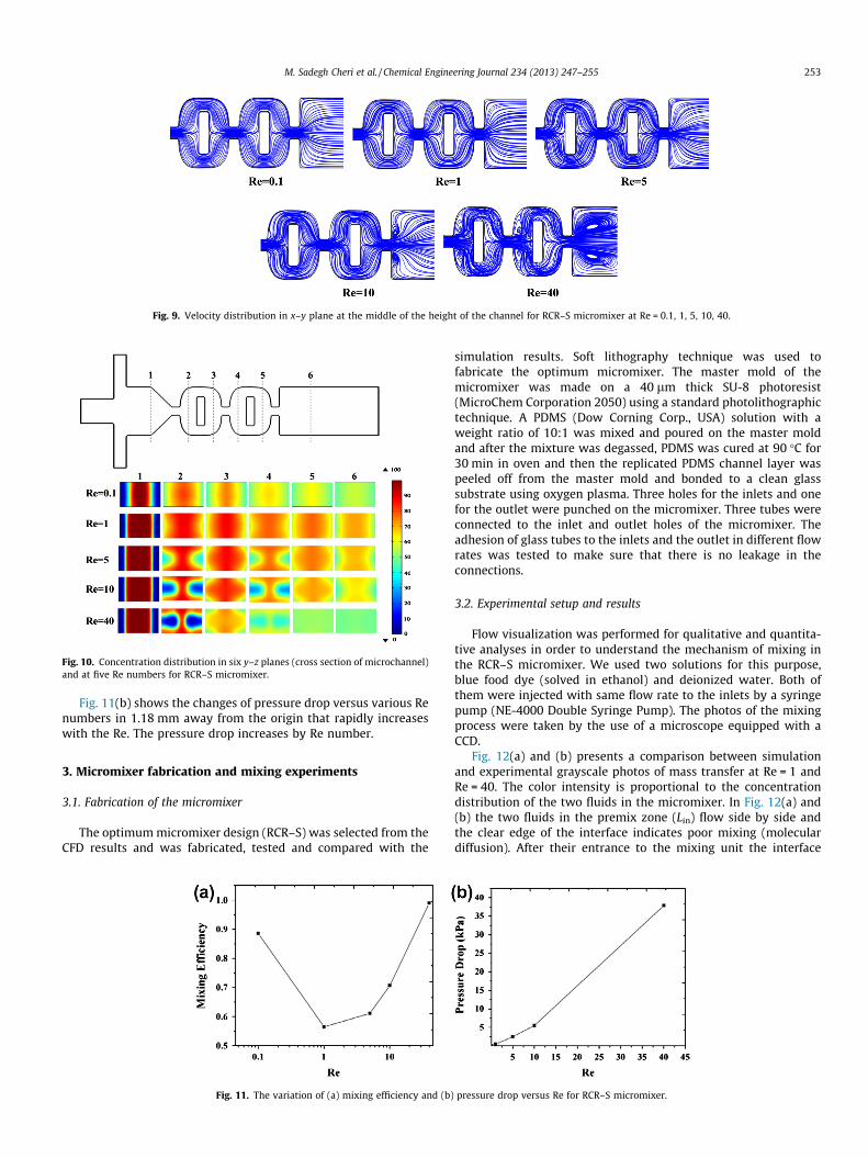
Fig. 9. Velocity distribution in x–y plane at the middle of the height of the channel for RCR–S micromixer at Re = 0.1, 1, 5, 10, 40.
Fig. 10. Concentration distribution in six y–z planes (cross section of microchannel)and at five Re numbers for RCR–S micromixer.
M. Sadegh Cheri et al. / Chemical Engineering Journal 234 (2013) 247–255 253
Fig. 11(b) shows the changes of pressure drop versus various Renumbers in 1.18 mm away from the origin that rapidly increaseswith the Re. The pressure drop increases by Re number.
3. Micromixer fabrication and mixing experiments
3.1. Fabrication of the micromixer
The optimum micromixer design (RCR–S) was selected from theCFD results and was fabricated, tested and compared with the
Fig. 11. The variation of (a) mixing efficiency and (b)
simulation results. Soft lithography technique was used tofabricate the optimum micromixer. The master mold of themicromixer was made on a 40 lm thick SU-8 photoresist(MicroChem Corporation 2050) using a standard photolithographictechnique. A PDMS (Dow Corning Corp., USA) solution with aweight ratio of 10:1 was mixed and poured on the master moldand after the mixture was degassed, PDMS was cured at 90 �C for30 min in oven and then the replicated PDMS channel layer waspeeled off from the master mold and bonded to a clean glasssubstrate using oxygen plasma. Three holes for the inlets and onefor the outlet were punched on the micromixer. Three tubes wereconnected to the inlet and outlet holes of the micromixer. Theadhesion of glass tubes to the inlets and the outlet in different flowrates was tested to make sure that there is no leakage in theconnections.
3.2. Experimental setup and results
Flow visualization was performed for qualitative and quantita-tive analyses in order to understand the mechanism of mixing inthe RCR–S micromixer. We used two solutions for this purpose,blue food dye (solved in ethanol) and deionized water. Both ofthem were injected with same flow rate to the inlets by a syringepump (NE-4000 Double Syringe Pump). The photos of the mixingprocess were taken by the use of a microscope equipped with aCCD.
Fig. 12(a) and (b) presents a comparison between simulationand experimental grayscale photos of mass transfer at Re = 1 andRe = 40. The color intensity is proportional to the concentrationdistribution of the two fluids in the micromixer. In Fig. 12(a) and(b) the two fluids in the premix zone (Lin) flow side by side andthe clear edge of the interface indicates poor mixing (moleculardiffusion). After their entrance to the mixing unit the interface
pressure drop versus Re for RCR–S micromixer.
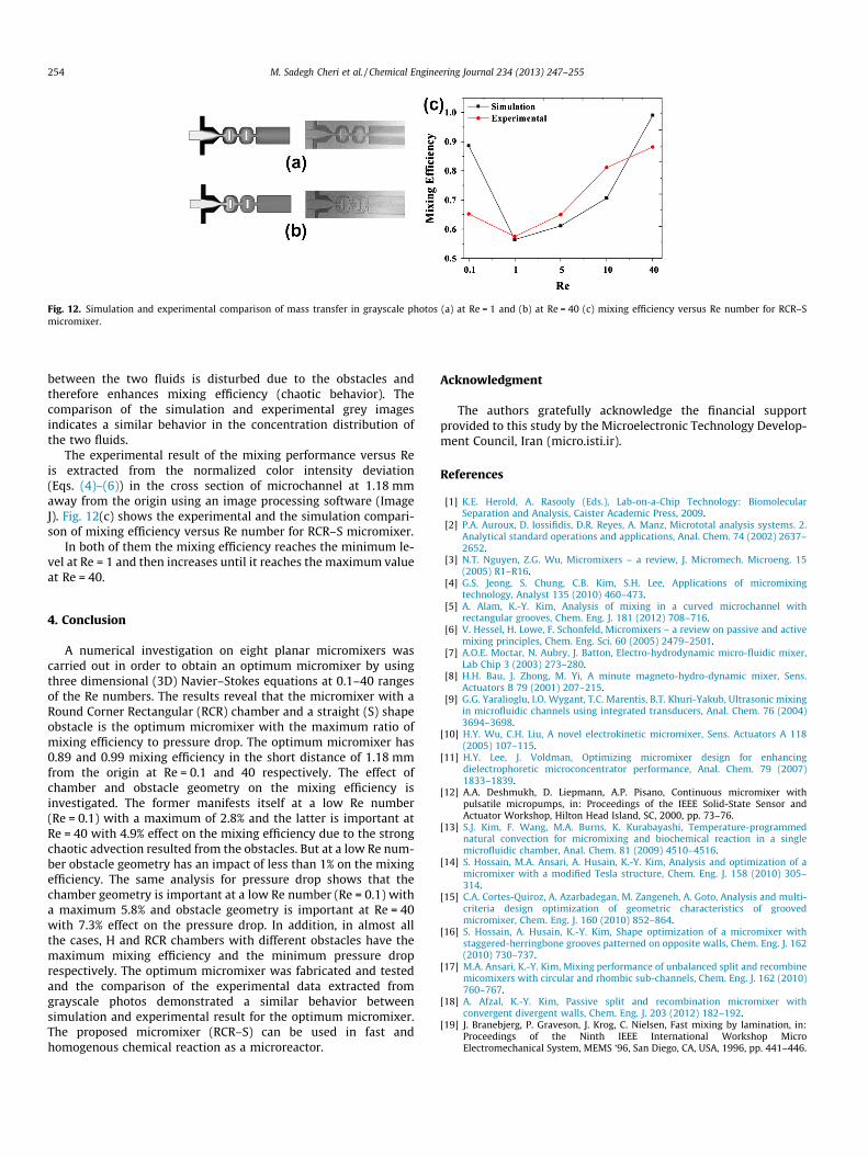
Fig. 12. Simulation and experimental comparison of mass transfer in grayscale photos (a) at Re = 1 and (b) at Re = 40 (c) mixing efficiency versus Re number for RCR–Smicromixer.
254 M. Sadegh Cheri et al. / Chemical Engineering Journal 234 (2013) 247–255
between the two fluids is disturbed due to the obstacles andtherefore enhances mixing efficiency (chaotic behavior). Thecomparison of the simulation and experimental grey imagesindicates a similar behavior in the concentration distribution ofthe two fluids.
The experimental result of the mixing performance versus Reis extracted from the normalized color intensity deviation(Eqs. (4)–(6)) in the cross section of microchannel at 1.18 mmaway from the origin using an image processing software (ImageJ). Fig. 12(c) shows the experimental and the simulation compari-son of mixing efficiency versus Re number for RCR–S micromixer.
In both of them the mixing efficiency reaches the minimum le-vel at Re = 1 and then increases until it reaches the maximum valueat Re = 40.
4. Conclusion
A numerical investigation on eight planar micromixers wascarried out in order to obtain an optimum micromixer by usingthree dimensional (3D) Navier–Stokes equations at 0.1–40 rangesof the Re numbers. The results reveal that the micromixer with aRound Corner Rectangular (RCR) chamber and a straight (S) shapeobstacle is the optimum micromixer with the maximum ratio ofmixing efficiency to pressure drop. The optimum micromixer has0.89 and 0.99 mixing efficiency in the short distance of 1.18 mmfrom the origin at Re = 0.1 and 40 respectively. The effect ofchamber and obstacle geometry on the mixing efficiency isinvestigated. The former manifests itself at a low Re number(Re = 0.1) with a maximum of 2.8% and the latter is important atRe = 40 with 4.9% effect on the mixing efficiency due to the strongchaotic advection resulted from the obstacles. But at a low Re num-ber obstacle geometry has an impact of less than 1% on the mixingefficiency. The same analysis for pressure drop shows that thechamber geometry is important at a low Re number (Re = 0.1) witha maximum 5.8% and obstacle geometry is important at Re = 40with 7.3% effect on the pressure drop. In addition, in almost allthe cases, H and RCR chambers with different obstacles have themaximum mixing efficiency and the minimum pressure droprespectively. The optimum micromixer was fabricated and testedand the comparison of the experimental data extracted fromgrayscale photos demonstrated a similar behavior betweensimulation and experimental result for the optimum micromixer.The proposed micromixer (RCR–S) can be used in fast andhomogenous chemical reaction as a microreactor.
Acknowledgment
The authors gratefully acknowledge the financial supportprovided to this study by the Microelectronic Technology Develop-ment Council, Iran (micro.isti.ir).
References
[1] K.E. Herold, A. Rasooly (Eds.), Lab-on-a-Chip Technology: BiomolecularSeparation and Analysis, Caister Academic Press, 2009.
[2] P.A. Auroux, D. Iossifidis, D.R. Reyes, A. Manz, Micrototal analysis systems. 2.Analytical standard operations and applications, Anal. Chem. 74 (2002) 2637–2652.
[3] N.T. Nguyen, Z.G. Wu, Micromixers – a review, J. Micromech. Microeng. 15(2005) R1–R16.
[4] G.S. Jeong, S. Chung, C.B. Kim, S.H. Lee, Applications of micromixingtechnology, Analyst 135 (2010) 460–473.
[5] A. Alam, K.-Y. Kim, Analysis of mixing in a curved microchannel withrectangular grooves, Chem. Eng. J. 181 (2012) 708–716.
[6] V. Hessel, H. Lowe, F. Schonfeld, Micromixers – a review on passive and activemixing principles, Chem. Eng. Sci. 60 (2005) 2479–2501.
[7] A.O.E. Moctar, N. Aubry, J. Batton, Electro-hydrodynamic micro-fluidic mixer,Lab Chip 3 (2003) 273–280.
[8] H.H. Bau, J. Zhong, M. Yi, A minute magneto-hydro-dynamic mixer, Sens.Actuators B 79 (2001) 207–215.
[9] G.G. Yaralioglu, I.O. Wygant, T.C. Marentis, B.T. Khuri-Yakub, Ultrasonic mixingin microfluidic channels using integrated transducers, Anal. Chem. 76 (2004)3694–3698.
[10] H.Y. Wu, C.H. Liu, A novel electrokinetic micromixer, Sens. Actuators A 118(2005) 107–115.
[11] H.Y. Lee, J. Voldman, Optimizing micromixer design for enhancingdielectrophoretic microconcentrator performance, Anal. Chem. 79 (2007)1833–1839.
[12] A.A. Deshmukh, D. Liepmann, A.P. Pisano, Continuous micromixer withpulsatile micropumps, in: Proceedings of the IEEE Solid-State Sensor andActuator Workshop, Hilton Head Island, SC, 2000, pp. 73–76.
[13] S.J. Kim, F. Wang, M.A. Burns, K. Kurabayashi, Temperature-programmednatural convection for micromixing and biochemical reaction in a singlemicrofluidic chamber, Anal. Chem. 81 (2009) 4510–4516.
[14] S. Hossain, M.A. Ansari, A. Husain, K.-Y. Kim, Analysis and optimization of amicromixer with a modified Tesla structure, Chem. Eng. J. 158 (2010) 305–314.
[15] C.A. Cortes-Quiroz, A. Azarbadegan, M. Zangeneh, A. Goto, Analysis and multi-criteria design optimization of geometric characteristics of groovedmicromixer, Chem. Eng. J. 160 (2010) 852–864.
[16] S. Hossain, A. Husain, K.-Y. Kim, Shape optimization of a micromixer withstaggered-herringbone grooves patterned on opposite walls, Chem. Eng. J. 162(2010) 730–737.
[17] M.A. Ansari, K.-Y. Kim, Mixing performance of unbalanced split and recombinemicomixers with circular and rhombic sub-channels, Chem. Eng. J. 162 (2010)760–767.
[18] A. Afzal, K.-Y. Kim, Passive split and recombination micromixer withconvergent divergent walls, Chem. Eng. J. 203 (2012) 182–192.
[19] J. Branebjerg, P. Graveson, J. Krog, C. Nielsen, Fast mixing by lamination, in:Proceedings of the Ninth IEEE International Workshop MicroElectromechanical System, MEMS ‘96, San Diego, CA, USA, 1996, pp. 441–446.

M. Sadegh Cheri et al. / Chemical Engineering Journal 234 (2013) 247–255 255
[20] S. Hossain, M.A. Ansari, K.-Y. Kim, Evaluation of the mixing performance ofthree passive micromixers, Chem. Eng. J. 150 (2009) 492–501.
[21] A.D. Stroock, S.K. Dertinger, A. Ajdari, I. Mezic, H.A. Stone, G.M. Whitesides,Chaotic mixer for microchannels, Science 295 (2002) 647–651.
[22] Y. Fang, Y. Ye, R. Shen, P. Zhu, R. Guo, Y. Hu, L. Wu, Mixing enhancement bysimple periodic geometric features in microchannels, Chem. Eng. J. 187 (2012)306–310.
[23] H. Wang, P. Iovenitti, E. Harvey, S. Masood, Optimizing layout of obstaclesfor enhanced mixing in microchannels, Smart Mater. Struct. 11 (2002) 662–667.
[24] C.K. Chung, T.R. Shih, C.K. Chang, C.W. Lai, B.H. Wu, Design and experiments ofa short mixing-length baffled microreactor and its application to microfluidicsynthesis of nanoparticles, Chem. Eng. J. 168 (2011) 790–798.
[25] T.R. Shih, C.K. Chung, A high-efficiency planar micromixer with convection anddiffusion mixing over a wide Reynolds number range, Microfluid. Nanofluid. 5(2008) 175–183.
[26] S.A. Khan, A. Gunther, M.A. Schmidt, K.F. Jensen, Microfluidic synthesis ofcolloidal silica, Langmuir 20 (2004) 8604–8611.
[27] S.A. Khan, K.F. Jensen, Microfluidic synthesis of titania shells on colloidal silica,Adv. Mater. 19 (2007) 2556–2560.