Embed Size (px)
Citation preview
Planar LookThru Transparent OLED Display
Fabricator’s Guide
2 Planar LookThru Fabricator’s Guide 020-1315-00A
Table of Contents
Table of Contents ...................................................................................................................................................................... 2 What’s in the Fabricator’s Guide .......................................................................................................................................... 3 What’s in the Box ....................................................................................................................................................................... 3
Display ...................................................................................................................................................................................... 3 Counterweight Plate ............................................................................................................................................................ 3 Cable Cover ............................................................................................................................................................................. 3 HDMI and Power Cables ..................................................................................................................................................... 3 Remote and Sensor .............................................................................................................................................................. 4 Quick Start Guide and USB Drive..................................................................................................................................... 4
Optional Accessories ................................................................................................................................................................ 4 Platform Cover ....................................................................................................................................................................... 4 Tiling Kit .................................................................................................................................................................................... 4 Base Plates ............................................................................................................................................................................... 7
Introduction to the Planar LookThru Transparent OLED Display ............................................................................. 7 Short Description of OLED Technology and Planar LookThru OLED Design .................................................. 7 Safe Handling ......................................................................................................................................................................... 8 Cleaning ................................................................................................................................................................................... 9 Environmental Considerations ..................................................................................................................................... 10
How are going to use your Planar LookThru Transparent OLED Display? ......................................................... 10 General Instructions .......................................................................................................................................................... 11
Mechanical Considerations ................................................................................................................................................. 11 Electrical ................................................................................................................................................................................ 11 Thermal .................................................................................................................................................................................. 11 Tabletop Installation ......................................................................................................................................................... 12 Mounting .............................................................................................................................................................................. 12
Optical Considerations ......................................................................................................................................................... 14 Luminance ............................................................................................................................................................................ 14 Transparency ....................................................................................................................................................................... 14 Sunlight ................................................................................................................................................................................. 15
User-Provided Touch ............................................................................................................................................................. 15 Content....................................................................................................................................................................................... 15 Safety Considerations ........................................................................................................................................................... 16
Structural............................................................................................................................................................................... 16 Glass ........................................................................................................................................................................................ 16 Thermal .................................................................................................................................................................................. 16
Specifications ........................................................................................................................................................................... 17 Line Drawings .......................................................................................................................................................................... 19 Regulatory Information ........................................................................................................................................................ 23
3 Planar LookThru Fabricator’s Guide 020-1315-00A
What’s in the Fabricator’s Guide
This document is intended to give guidelines and help for installers and fabricators working with the Planar® LookThru™ Transparent OLED display. This document is not meant to replace the manual, nor will it provide specifics on how to work in each environment where a Planar LookThru Transparent OLED display might be installed. Instead, this document will provide expert fabricators and installers with the information and understanding necessary to make the most of Planar LookThru displays.
Detailed specification and instructions on operating the Planar LookThru display can be found in the User Manual.
What’s in the Box
Display
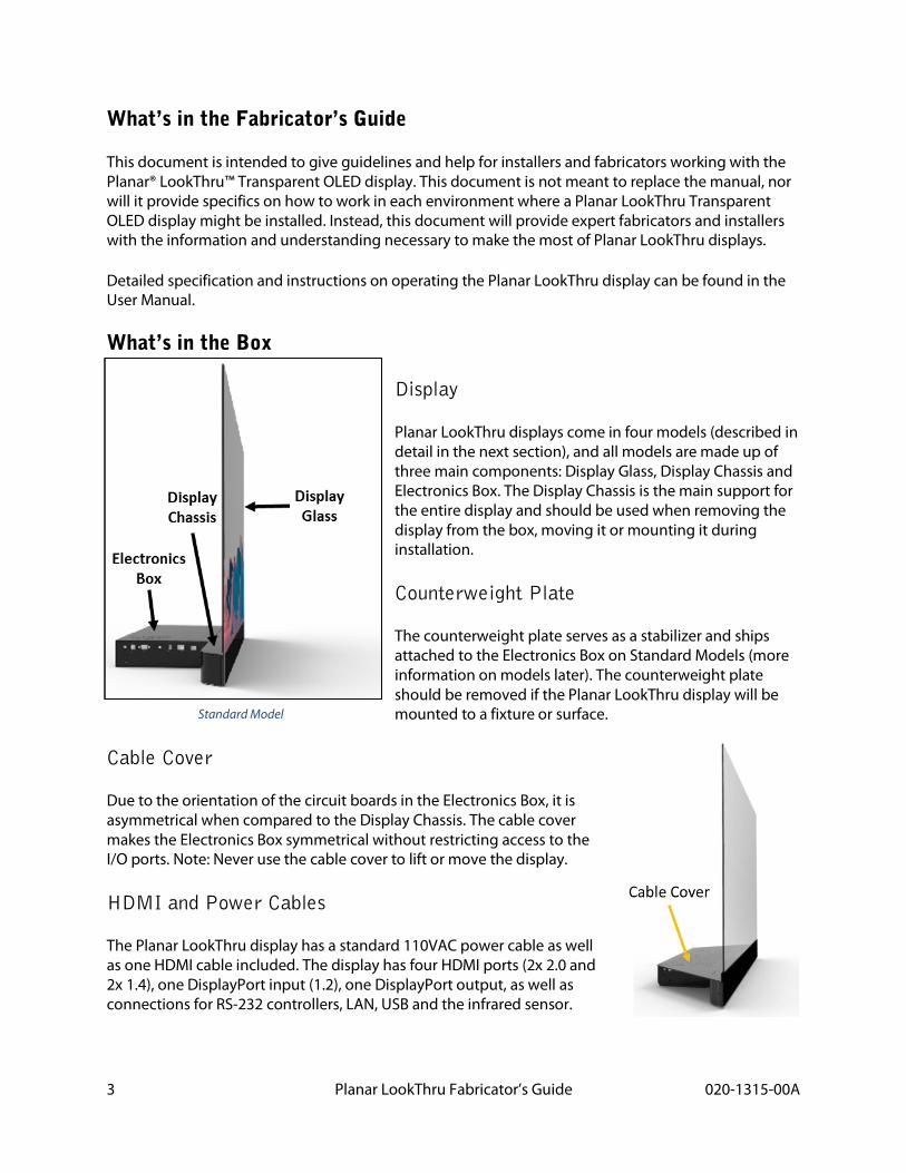
Planar LookThru displays come in four models (described in detail in the next section), and all models are made up of three main components: Display Glass, Display Chassis and Electronics Box. The Display Chassis is the main support for the entire display and should be used when removing the display from the box, moving it or mounting it during installation.
Counterweight Plate
The counterweight plate serves as a stabilizer and ships attached to the Electronics Box on Standard Models (more information on models later). The counterweight plate should be removed if the Planar LookThru display will be mounted to a fixture or surface.
Cable Cover
Due to the orientation of the circuit boards in the Electronics Box, it is asymmetrical when compared to the Display Chassis. The cable cover makes the Electronics Box symmetrical without restricting access to the I/O ports. Note: Never use the cable cover to lift or move the display.
HDMI and Power Cables
The Planar LookThru display has a standard 110VAC power cable as well as one HDMI cable included. The display has four HDMI ports (2x 2.0 and 2x 1.4), one DisplayPort input (1.2), one DisplayPort output, as well as connections for RS-232 controllers, LAN, USB and the infrared sensor.
Standard Model
4 Planar LookThru Fabricator’s Guide 020-1315-00A
Remote and Sensor
You can control the Planar LookThru display with the included remote control through on On-Screen Display (OSD). To increase the range of the remote control, a 112-inch (2850mm) cable is also included.
Quick Start Guide and USB Drive
A printed guide with the basic information necessary to start and operate the Planar LookThru display is included, but the more detailed User Manual, Content Developer’s Guide and this Fabrication Guide are stored on the USB drive that is also in the box.
Optional Accessories
Depending on your installation needs some of the optional accessories may help to facilitate proper use of a Planar LookThru display.
Platform Cover
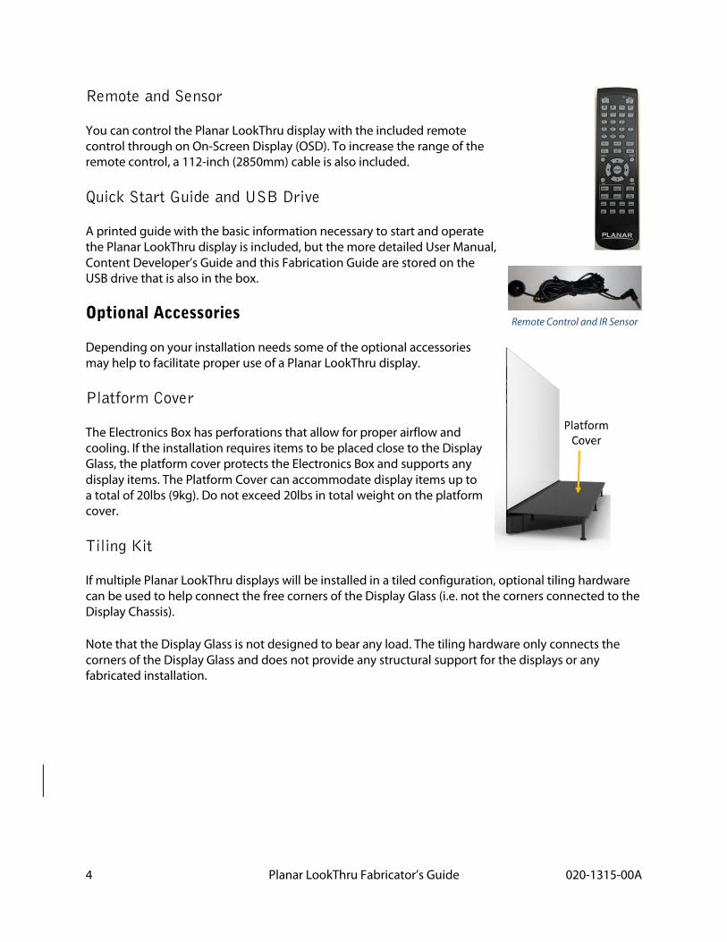
The Electronics Box has perforations that allow for proper airflow and cooling. If the installation requires items to be placed close to the Display Glass, the platform cover protects the Electronics Box and supports any display items. The Platform Cover can accommodate display items up to a total of 20lbs (9kg). Do not exceed 20lbs in total weight on the platform cover.
Tiling Kit
If multiple Planar LookThru displays will be installed in a tiled configuration, optional tiling hardware can be used to help connect the free corners of the Display Glass (i.e. not the corners connected to the Display Chassis).
Note that the Display Glass is not designed to bear any load. The tiling hardware only connects the corners of the Display Glass and does not provide any structural support for the displays or any fabricated installation.
Remote Control and IR Sensor
5 Planar LookThru Fabricator’s Guide 020-1315-00A
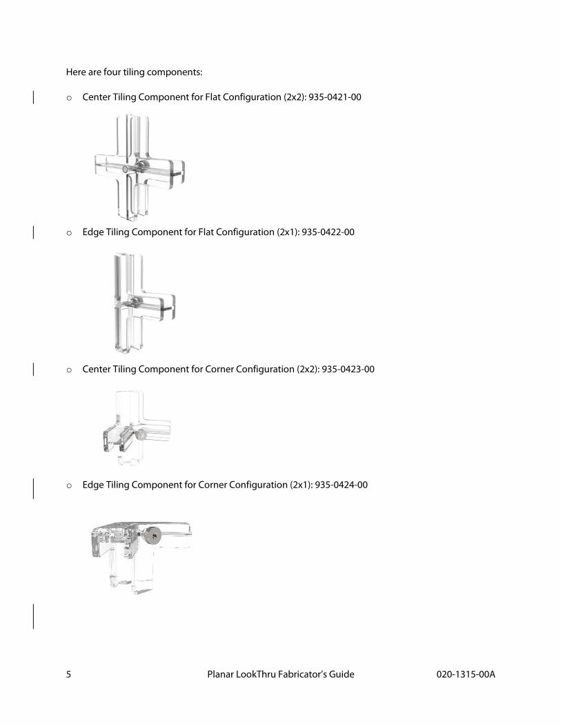
Here are four tiling components:
o Center Tiling Component for Flat Configuration (2x2): 935-0421-00
o Edge Tiling Component for Flat Configuration (2x1): 935-0422-00
o Center Tiling Component for Corner Configuration (2x2): 935-0423-00
o Edge Tiling Component for Corner Configuration (2x1): 935-0424-00
6 Planar LookThru Fabricator’s Guide 020-1315-00A
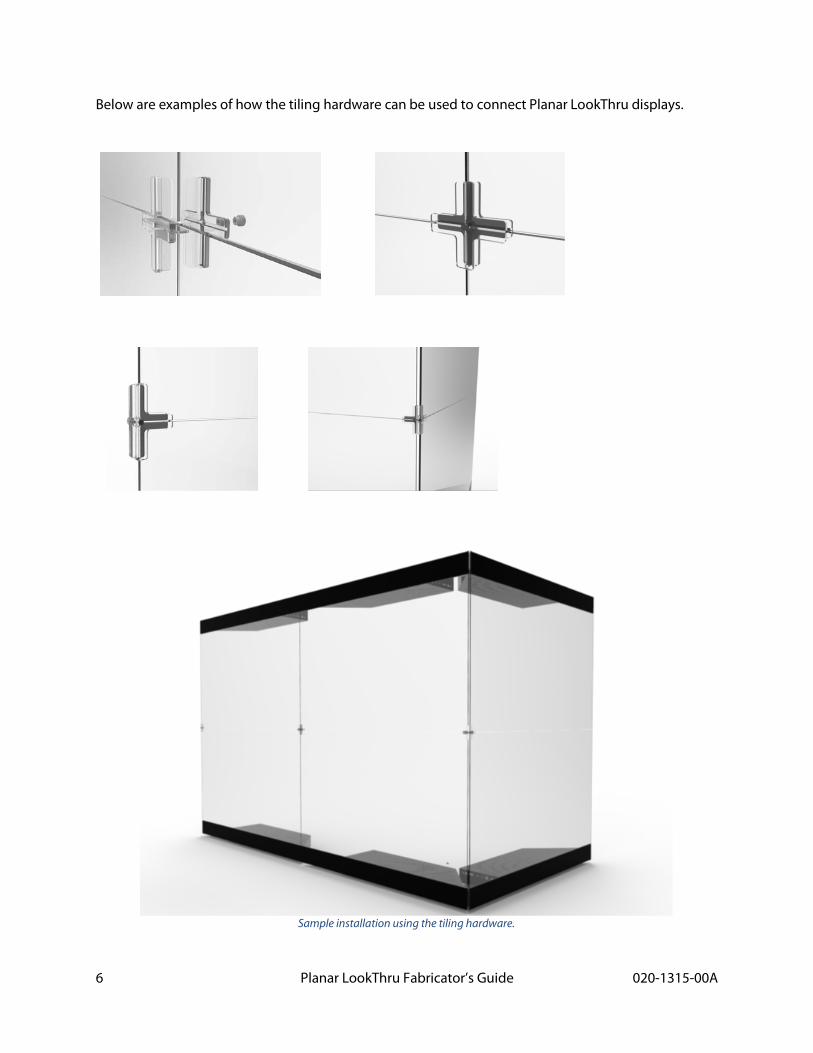
Below are examples of how the tiling hardware can be used to connect Planar LookThru displays.
Sample installation using the tiling hardware.
7 Planar LookThru Fabricator’s Guide 020-1315-00A
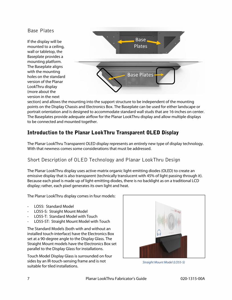
Base Plates
If the display will be mounted to a ceiling, wall or tabletop, the Baseplate provides a mounting platform. The Baseplate aligns with the mounting holes on the standard version of the Planar LookThru display (more about the version in the next section) and allows the mounting into the support structure to be independent of the mounting points on the Display Chassis and Electronics Box. The Baseplate can be used for either landscape or portrait orientation and is designed to accommodate standard wall studs that are 16-inches on center. The Baseplates provide adequate airflow for the Planar LookThru display and allow multiple displays to be connected and mounted together.
Introduction to the Planar LookThru Transparent OLED Display
The Planar LookThru Transparent OLED display represents an entirely new type of display technology. With that newness comes some considerations that must be addressed.
Short Description of OLED Technology and Planar LookThru Design
The Planar LookThru display uses active-matrix organic light-emitting diodes (OLED) to create an emissive display that is also transparent (technically translucent with 45% of light passing through it). Because each pixel is made up of light-emitting diodes, there is no backlight as on a traditional LCD display; rather, each pixel generates its own light and heat.
The Planar LookThru display comes in four models:
- LO55: Standard Model - LO55-S: Straight Mount Model - LO55-T: Standard Model with Touch - LO55-ST: Straight Mount Model with Touch
The Standard Models (both with and without an installed touch-interface) have the Electronics Box set at a 90-degree angle to the Display Glass. The Straight Mount models have the Electronics Box set parallel to the Display Glass for installations.
Touch Model Display Glass is surrounded on four sides by an IR-touch-sensing frame and is not suitable for tiled installations.
Straight Mount Model (LO55-S)
8 Planar LookThru Fabricator’s Guide 020-1315-00A
Front vs Rear Viewing
Because each pixel is emitting its own light, the display can be viewed from the back as well as the front (the back side being where the Electronics Box is located). However, the light emitted toward the rear is much less than that on the front and any image viewed from behind will be reversed.
Cooling Features
The Planar LookThru display generates significant heat that must be dissipated. The Electronics Box is perforated to allow for good airflow but installations must keep at least 0.25-inches (5mm) between the Electronics Box and the mounting surface and 0.5-inches (12mm) above the Electronics Box to allow for that airflow. Additionally, dust build-up can prevent adequate cooling so regular vacuuming must be facilitated in the installation to allow for the cooling features to work.
Glass Treatment
The front surface of the Display Glass is made of Corning® Gorilla® Glass that is bonded to the display and covered with an anti-reflective coating. The Corning Gorilla Glass provides scratch resistance on the front of the display only. The back side of the display is susceptible to damage from sharp and/or hard objects and should be protected accordingly.
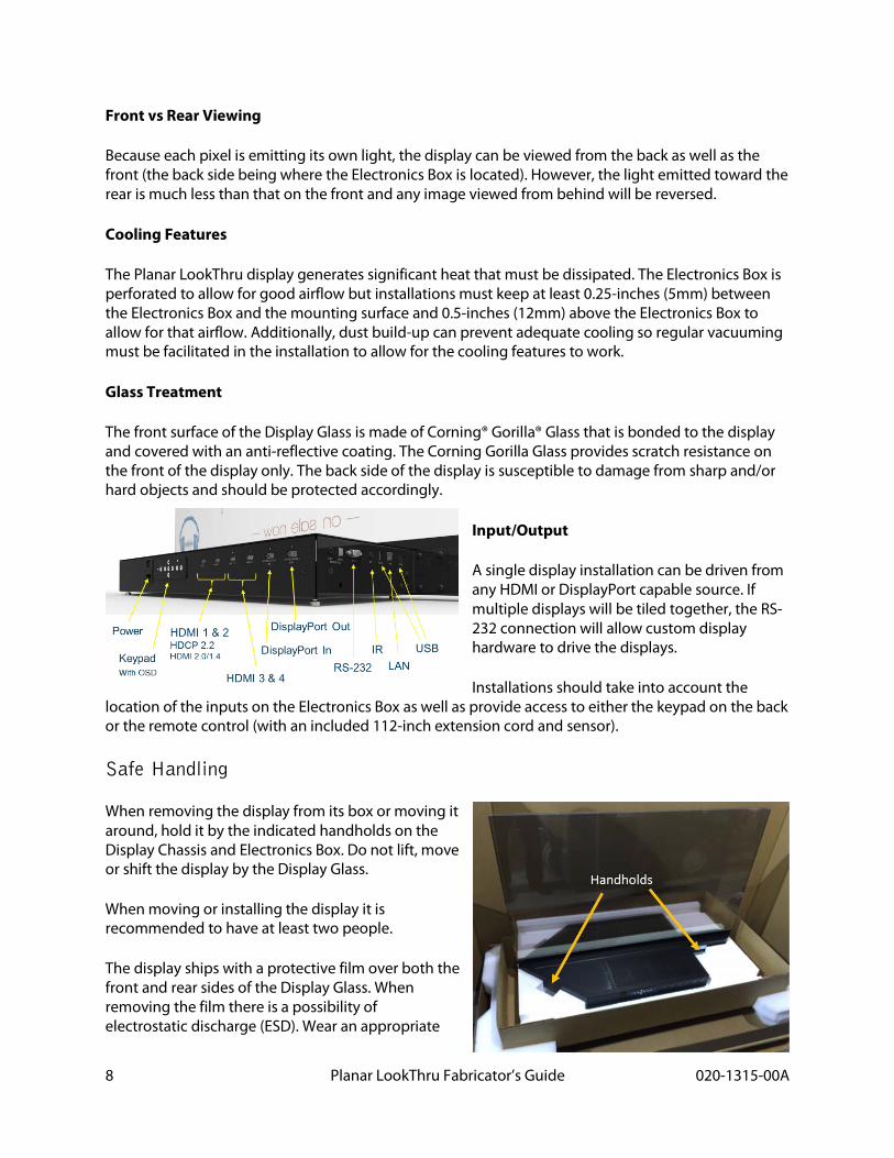
Input/Output
A single display installation can be driven from any HDMI or DisplayPort capable source. If multiple displays will be tiled together, the RS-232 connection will allow custom display hardware to drive the displays.
Installations should take into account the location of the inputs on the Electronics Box as well as provide access to either the keypad on the back or the remote control (with an included 112-inch extension cord and sensor).
Safe Handling
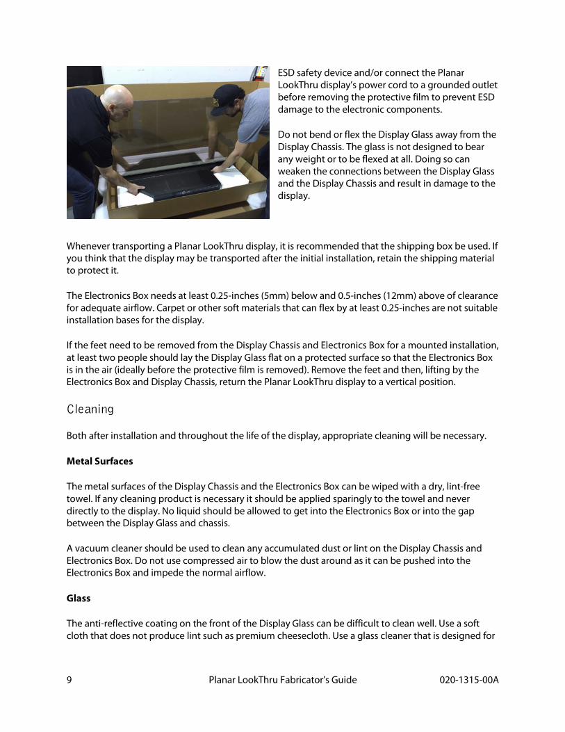
When removing the display from its box or moving it around, hold it by the indicated handholds on the Display Chassis and Electronics Box. Do not lift, move or shift the display by the Display Glass.
When moving or installing the display it is recommended to have at least two people.
The display ships with a protective film over both the front and rear sides of the Display Glass. When removing the film there is a possibility of electrostatic discharge (ESD). Wear an appropriate
9 Planar LookThru Fabricator’s Guide 020-1315-00A
ESD safety device and/or connect the Planar LookThru display’s power cord to a grounded outlet before removing the protective film to prevent ESD damage to the electronic components.
Do not bend or flex the Display Glass away from the Display Chassis. The glass is not designed to bear any weight or to be flexed at all. Doing so can weaken the connections between the Display Glass and the Display Chassis and result in damage to the display.
Whenever transporting a Planar LookThru display, it is recommended that the shipping box be used. If you think that the display may be transported after the initial installation, retain the shipping material to protect it.
The Electronics Box needs at least 0.25-inches (5mm) below and 0.5-inches (12mm) above of clearance for adequate airflow. Carpet or other soft materials that can flex by at least 0.25-inches are not suitable installation bases for the display.
If the feet need to be removed from the Display Chassis and Electronics Box for a mounted installation, at least two people should lay the Display Glass flat on a protected surface so that the Electronics Box is in the air (ideally before the protective film is removed). Remove the feet and then, lifting by the Electronics Box and Display Chassis, return the Planar LookThru display to a vertical position.
Cleaning
Both after installation and throughout the life of the display, appropriate cleaning will be necessary.
Metal Surfaces
The metal surfaces of the Display Chassis and the Electronics Box can be wiped with a dry, lint-free towel. If any cleaning product is necessary it should be applied sparingly to the towel and never directly to the display. No liquid should be allowed to get into the Electronics Box or into the gap between the Display Glass and chassis.
A vacuum cleaner should be used to clean any accumulated dust or lint on the Display Chassis and Electronics Box. Do not use compressed air to blow the dust around as it can be pushed into the Electronics Box and impede the normal airflow.
Glass
The anti-reflective coating on the front of the Display Glass can be difficult to clean well. Use a soft cloth that does not produce lint such as premium cheesecloth. Use a glass cleaner that is designed for

10 Planar LookThru Fabricator’s Guide 020-1315-00A
LCD displays. If there are stubborn smudges or sticky substances on the glass, high-quality isopropyl alcohol can be used to remove the substance before using standard glass cleaner.
As with the Electronics Box and Display Chassis, always apply cleaning solution to the cloth in moderate amounts and then wipe the cloth on the Display Glass. Never apply cleaning solution or isopropyl alcohol directly to the Display Glass.
Avoid touching or wiping the exposed edge of the Planar LookThru LO55 and LO55-S models (standard and standard Straight Mount) as the silicon bead that seals the edge of the glass may allow some silicon onto the Display Glass surface and mar the anti-reflective coating.
Environmental Considerations
Planar LookThru displays are designed for indoor installations not subjected to direct sunlight or extreme temperatures.
Normal use for the display is considered to be 12 hours per day at 25ºC (77ºF), moving images and 75 nits average luminance on the display.
The ambient temperature should not be below 0ºC (32ºF) nor exceed 40ºC (104ºF) as measured within 24-inches (610mm) of the Electronics Box.
The relative humidity should be kept between 20 and 95% where the Planar LookThru display is installed.
Planar LookThru displays should not be installed or operated outdoors or in direct sunlight (even through a window). The display will not be readable in direct sunlight and the ultra-violet radiation will reduce the lifespan of the display.
The Planar LookThru display does not have a UV protective coating to ensure the best possible image quality so the installation location must protect the display from UV radiation via direct sunlight (i.e. not through a window) or other UV sources (e.g. full-spectrum lighting) that might shine on the display.
Adequate lighting behind the Display Glass will affect the appearance of transparency (similar to window glass) so lights may need to shine near the Display Glass for your installation to work; however, ensure that heat-producing lights do not shine directly onto the Display Glass or introduce heat to the Display Glass.
If it is not possible to keep light sources away from the Display Glass, use low-heat light sources such as LED or CFL bulbs. Avoid incandescent and/or halogen-type bulbs near the Display Glass.
How are going to use your Planar LookThru Display?
The Planar LookThru display is ideal for many types of installations including hospitality, exhibit displays, retail displays, wayfinding and entertainment. The specifics of how you install display will determine the environmental and mechanical needs you will face.
11 Planar LookThru Fabricator’s Guide 020-1315-00A
General Instructions
Planar LookThru displays can be installed vertically or horizontally (in portrait or landscape orientation) with the Electronics Box facing up, down, left or right.
When installing a Planar LookThru display, it must be supported by the mounting points in the Display Chassis (primary) and mounting points on the Electronics Box (secondary) and NOT by the Display Glass. There are 5 primary mount points on the Display Chassis that receive M6 threaded screws. At least 3 of the 5 primary mounting points must be used when installing the display.
The angle of the mount points should be adjusted to align the Display Glass rather than attempting to move the Display Glass. For example, the optional base should be shimmed so that the display is level rather than attempting to adjust the angle of the Display Glass to align it properly.
The glass should not be bent, torqued or subjected to any weight-load.
Disclaimer: Proper installation Planar LookThru Transparent OLED displays is the responsibility of the customer. Failure to follow safety and installation guidelines from this manual, or installation of the display in a manner not covered in this document, is the responsibility of the installer and/or end customer.
Mechanical Considerations
Electrical
Each Planar LookThru display has an average power consumption of between 100 and 130W with a peak consumption of 145W when the display is completely white (more pixels lit equals more power used). The standby power for the display is less than 0.5W.
The power supply can accept inputs between 100 and 240V at 50 to 60Hz.
Ensure that the power circuit on which you install a Planar LookThru display can handle not only the average current, but also the peak current, to avoid tripping circuit breakers or creating a fire hazard.
For example 145W at 110V draws 1.3A of current, a 0.4A spike from the average. At 220V the 145W peak would draw only 0.66A, however.
Thermal
The Planar LookThru Display Glass produces negligible heat but should be protected from direct heat sources such as incandescent or halogen lights. The Electronics Box and Display Chassis produce the majority of the heat from the display’s electronics and must be allowed adequate air circulation.
To prevent ambient noise, the Electronics Box is designed to keep cool without the need for a fan so long as normal airflow is permitted. A sealed, enclosed box would restrict the airflow and increase the ambient temperature outside the Planar LookThru display’s operating range (0º to 40ºC). If the
12 Planar LookThru Fabricator’s Guide 020-1315-00A
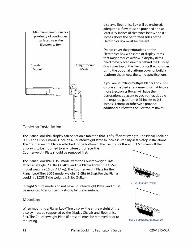
display’s Electronics Box will be enclosed, adequate airflow must be provided and at least 0.25-inches of clearance below and 0.5-inches above the perforated sides of the Electronics Box must be present.
Do not cover the perforations on the Electronics Box with cloth or display items that might reduce airflow. If display items need to be placed directly behind the Display Glass over top of the Electronics Box, consider using the optional platform cover or build a platform that meets the same specifications.
If you are installing multiple Planar LookThru displays in a tiled arrangement so that two or more Electronics Boxes will have their perforations adjacent to each other, double the required gap from 0.25-inches to 0.5-inches (12mm), or otherwise provide additional airflow to the Electronics Boxes.
Tabletop Installation
The Planar LookThru display can be set on a tabletop that is of sufficient strength. The Planar LookThru LO55 and LO55-T models include a Counterweight Plate to increase stability in tabletop installations. The Counterweight Plate is attached to the bottom of the Electronics Box with 3 M6 screws. If the display is to be mounted to any fixture or surface, the Counterweight Plate should be removed first.
The Planar LookThru LO55 model with the Counterweight Plate attached weighs 73.5lbs (33.4kg) and the Planar LookThru LO55-T model weighs 90.5lbs (41.1kg). The Counterweight Plate for the Planar LookThru LO55 model weighs 13.6lbs (6.2kg). For the Planar LookThru LO55-T the weight is 21lbs (9.5kg).
Straight Mount models do not have Counterweight Plates and must be mounted to a sufficiently strong fixture or surface.
Mounting
When mounting a Planar LookThru display, the entire weight of the display must be supported by the Display Chassis and Electronics Box. The Counterweight Plate (if present) must be removed prior to mounting.
LO55 Standard Design
LO55-S Straight Mount Design
13 Planar LookThru Fabricator’s Guide 020-1315-00A
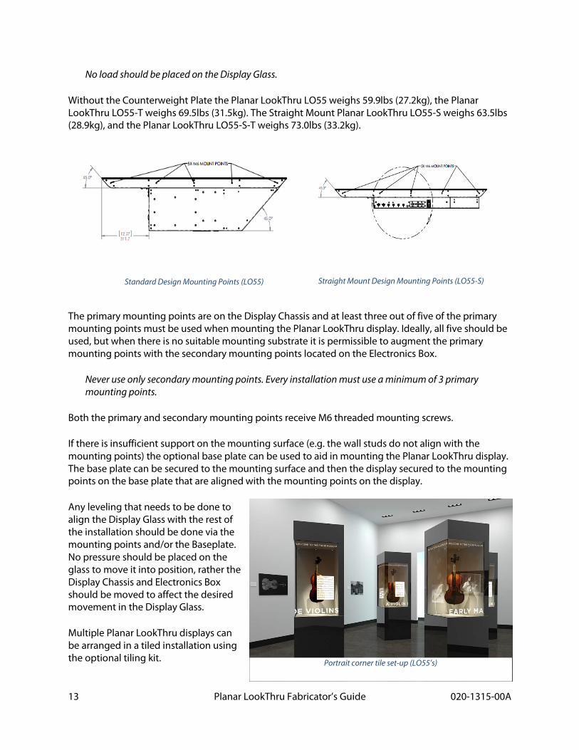
No load should be placed on the Display Glass.
Without the Counterweight Plate the Planar LookThru LO55 weighs 59.9lbs (27.2kg), the Planar LookThru LO55-T weighs 69.5lbs (31.5kg). The Straight Mount Planar LookThru LO55-S weighs 63.5lbs (28.9kg), and the Planar LookThru LO55-S-T weighs 73.0lbs (33.2kg).
The primary mounting points are on the Display Chassis and at least three out of five of the primary mounting points must be used when mounting the Planar LookThru display. Ideally, all five should be used, but when there is no suitable mounting substrate it is permissible to augment the primary mounting points with the secondary mounting points located on the Electronics Box.
Never use only secondary mounting points. Every installation must use a minimum of 3 primary mounting points.
Both the primary and secondary mounting points receive M6 threaded mounting screws.
If there is insufficient support on the mounting surface (e.g. the wall studs do not align with the mounting points) the optional base plate can be used to aid in mounting the Planar LookThru display. The base plate can be secured to the mounting surface and then the display secured to the mounting points on the base plate that are aligned with the mounting points on the display.
Any leveling that needs to be done to align the Display Glass with the rest of the installation should be done via the mounting points and/or the Baseplate. No pressure should be placed on the glass to move it into position, rather the Display Chassis and Electronics Box should be moved to affect the desired movement in the Display Glass.
Multiple Planar LookThru displays can be arranged in a tiled installation using the optional tiling kit.
Standard Design Mounting Points (LO55) Straight Mount Design Mounting Points (LO55-S)
Portrait corner tile set-up (LO55’s)
14 Planar LookThru Fabricator’s Guide 020-1315-00A
The optional tiling components are connectors that clip the corners of the Display Glass together to prevent movement.
o Center Tiling Component for Flat Configuration (2x2): 935-0421-00 o Edge Tiling Component for Flat Configuration (2x1): 935-0422-00 o Center Tiling Component for Corner Configuration (2x2): 935-0423-00 o Edge Tiling Component for Corner Configuration (2x1): 935-0424-00
The clips do not provide any structural or load-bearing support. Each Planar LookThru display must be individually mounted and supported. The clips should not transfer a load from one display to another nor require the Display Glass to be moved or torqued to install. The purpose of the tiling clips is only to ensure that the glass remains in its installed position.
The free edges of the Display Glass on the non-touch models (LO55 & LO55-S) are treated with a silicon sealant to protect the AMOLED electronics inside. Avoid installations where the exposed edge can be handled by the public or will be subjected to wear to prevent degradation of the seal.
Optical Considerations
The strength and position of ambient lighting will greatly affect the visibility of what is displayed on the Planar LookThru display and what is seen through it.
Luminance
The average luminance of the Planar LookThru display is about 75 nits. While the actual lighting output of the display is not very much (a 100W incandescent bulb produces around 18,000 nits), the contrast between lit pixels and unlit (i.e. transparent) pixels provides a high effective contrast ratio.
When installing a Planar LookThru display it is important to illuminate anything behind the Display Glass that should be seen through the glass, but to keep that illumination low enough to not overpower the light output of the display itself. Unfortunately it is not possible to give specific numbers since distance from the Display Glass, ambient light and display content are all factors that affect the appearance of transparency and the readability of the display.
Transparency
It is suggested that before an installation is made final that the lighting behind the Display Glass be tested with the content running on the display to ensure the best possible transparency and visibility on the display. Dimmable lights for behind the Display Glass will provide flexibility and should be considered on all installations.
15 Planar LookThru Fabricator’s Guide 020-1315-00A
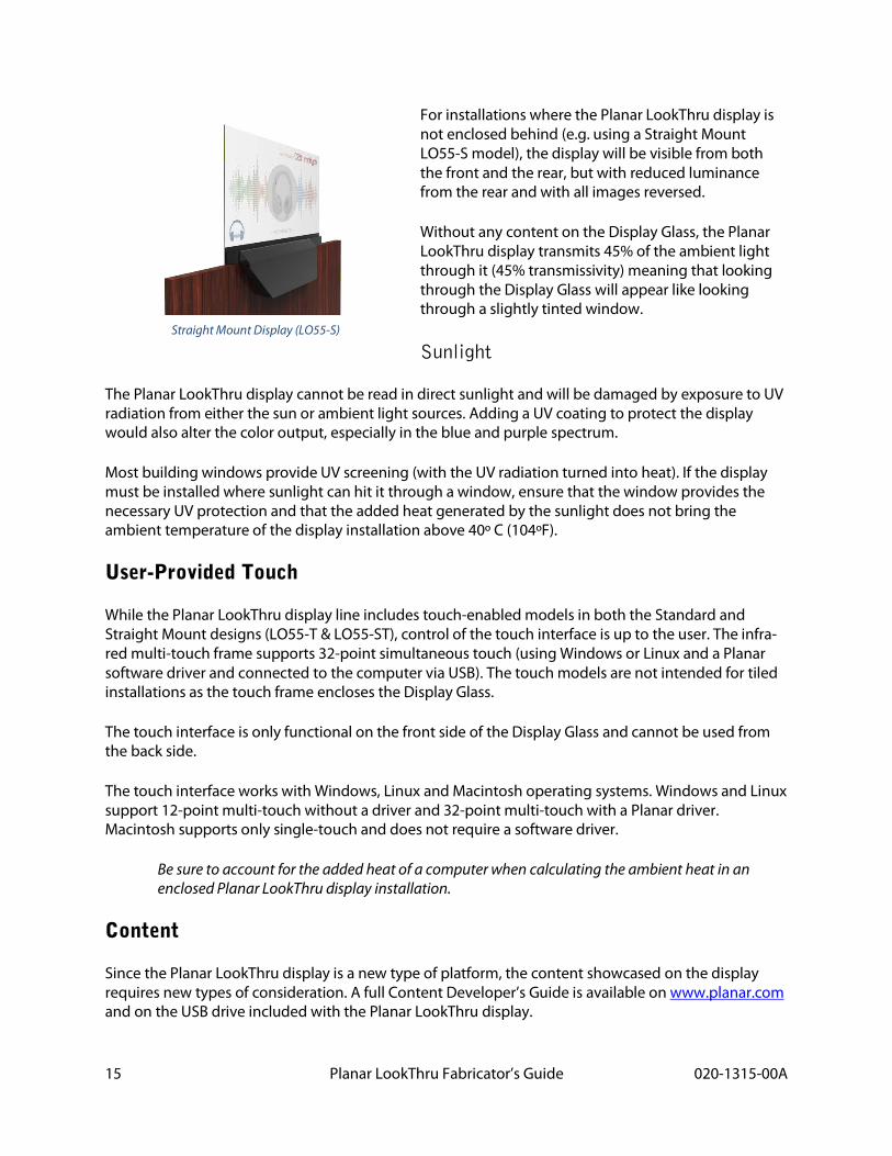
For installations where the Planar LookThru display is not enclosed behind (e.g. using a Straight Mount LO55-S model), the display will be visible from both the front and the rear, but with reduced luminance from the rear and with all images reversed.
Without any content on the Display Glass, the Planar LookThru display transmits 45% of the ambient light through it (45% transmissivity) meaning that looking through the Display Glass will appear like looking through a slightly tinted window.
Sunlight
The Planar LookThru display cannot be read in direct sunlight and will be damaged by exposure to UV radiation from either the sun or ambient light sources. Adding a UV coating to protect the display would also alter the color output, especially in the blue and purple spectrum.
Most building windows provide UV screening (with the UV radiation turned into heat). If the display must be installed where sunlight can hit it through a window, ensure that the window provides the necessary UV protection and that the added heat generated by the sunlight does not bring the ambient temperature of the display installation above 40º C (104ºF).
User-Provided Touch
While the Planar LookThru display line includes touch-enabled models in both the Standard and Straight Mount designs (LO55-T & LO55-ST), control of the touch interface is up to the user. The infra-red multi-touch frame supports 32-point simultaneous touch (using Windows or Linux and a Planar software driver and connected to the computer via USB). The touch models are not intended for tiled installations as the touch frame encloses the Display Glass.
The touch interface is only functional on the front side of the Display Glass and cannot be used from the back side.
The touch interface works with Windows, Linux and Macintosh operating systems. Windows and Linux support 12-point multi-touch without a driver and 32-point multi-touch with a Planar driver. Macintosh supports only single-touch and does not require a software driver.
Be sure to account for the added heat of a computer when calculating the ambient heat in an enclosed Planar LookThru display installation.
Content
Since the Planar LookThru display is a new type of platform, the content showcased on the display requires new types of consideration. A full Content Developer’s Guide is available on www.planar.com and on the USB drive included with the Planar LookThru display.
Straight Mount Display (LO55-S)
16 Planar LookThru Fabricator’s Guide 020-1315-00A
As a fabricator, it is important to align the installation with the content to deliver the best possible experience. For example, a content developer wanted to highlight different objects behind the Display Glass in an exhibit-style installation, the installation would benefit from a low-light interior (i.e. behind the Display Glass) with adjustable spotlights.
When fabricating for Planar LookThru displays, it should be considered as a part of the overall environment rather than a separate piece that provides a display in the environment. Content then becomes not simply an addition, like a poster on a wall, but something to be integrated like a window in a wall.
Safety Considerations
Structural
The Planar LookThru display is not a structural piece and cannot be used to support any portion of the installation. The full weight of the display must be supported by the primary and secondary mounting points on the Display Chassis and Electronics Box.
Glass
The glass on a Planar LookThru display is 2mm thick Corning® Gorilla® Glass covered (on the front side only) with an anti-reflective coating. As such the glass can withstand normal impacts and scratches as from being used as a touch interface, but it is not designed nor capable of bearing any loads.
Do not stress the glass or move it out of a 90-degree alignment with the Display Chassis. If the glass is accidentally moved out of alignment, relieve the pressure on it and all it to move back into its neutral position as soon as possible.
The rear side of the screen does not have an anti-reflective coating nor protective Corning® Gorilla® Glass. It should be protected from touches, scratches or impacts.
Thermal
The Planar LookThru display is designed to operate only between 0ºC (32ºF) nor exceed 40ºC (104ºF) ambient temperature. If lighting, heating, or the Electronics Box of the display will increase the ambient temperature above 40º, additional cooling measures must be installed to prevent damage to the display.
When operating within the appropriate temperature range, the Electronics Box requires 0.25-inches (5mm) of clearance below and 0.5-inches (12mm) above the perforated holes to allow for airflow. Dust and lint accumulation can restrict the airflow and should be addressed through either cleaning access (using a vacuum) or air filtration on the installation if vacuuming is not feasible.
17 Planar LookThru Fabricator’s Guide 020-1315-00A
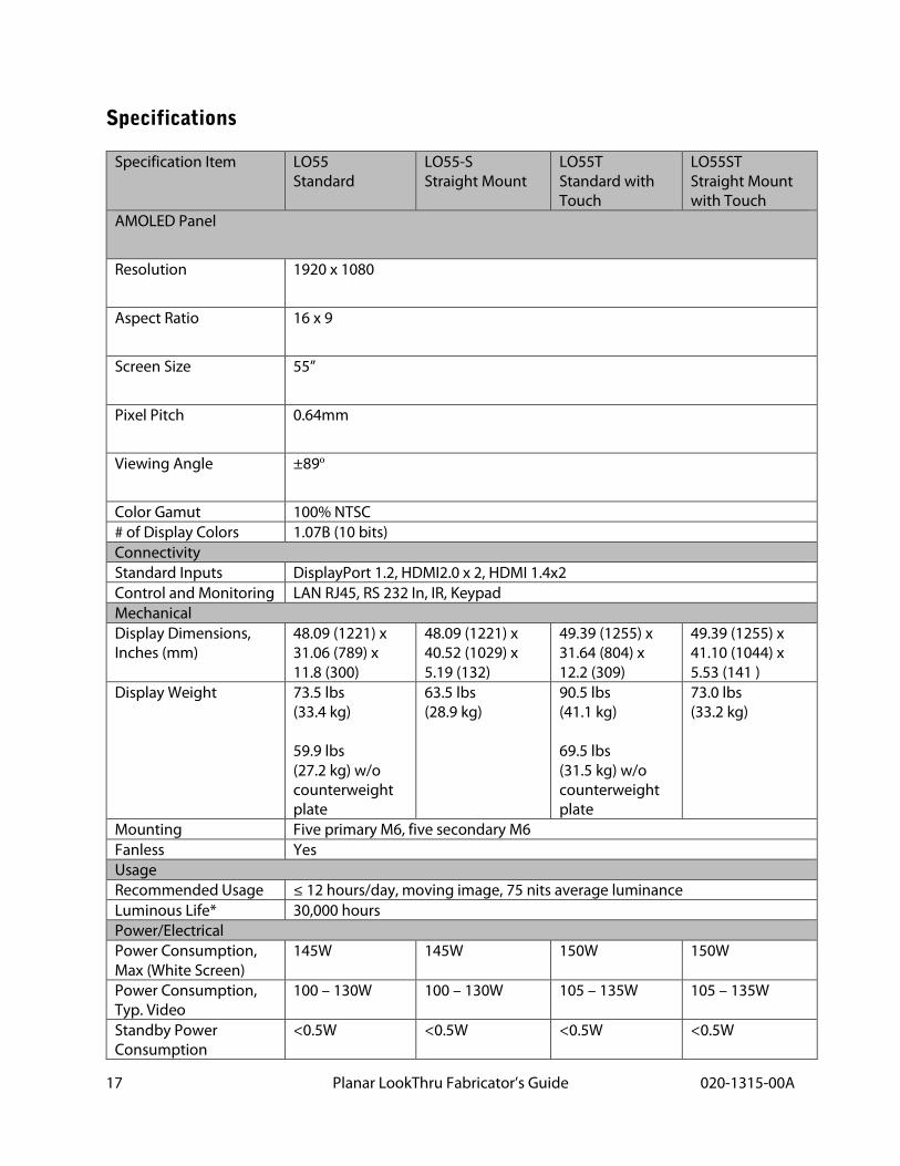
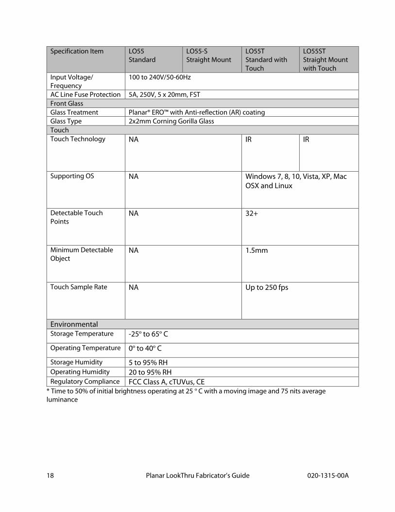
Specifications
Specification Item LO55 Standard
LO55-S Straight Mount
LO55T Standard with Touch
LO55ST Straight Mount with Touch
AMOLED Panel
Resolution 1920 x 1080
Aspect Ratio 16 x 9
Screen Size 55”
Pixel Pitch 0.64mm
Viewing Angle ±89º
Color Gamut 100% NTSC # of Display Colors 1.07B (10 bits) Connectivity Standard Inputs DisplayPort 1.2, HDMI2.0 x 2, HDMI 1.4x2 Control and Monitoring LAN RJ45, RS 232 In, IR, Keypad Mechanical Display Dimensions, Inches (mm)
48.09 (1221) x 31.06 (789) x 11.8 (300)
48.09 (1221) x 40.52 (1029) x 5.19 (132)
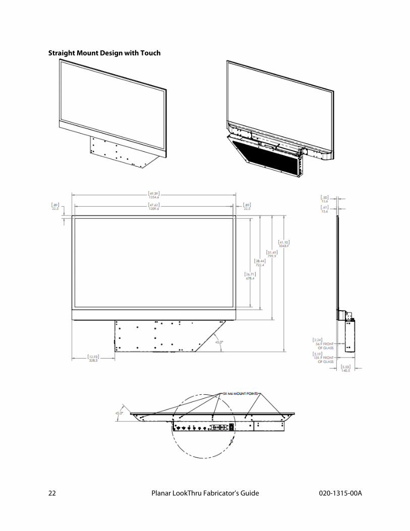
49.39 (1255) x 31.64 (804) x 12.2 (309)
49.39 (1255) x 41.10 (1044) x 5.53 (141 )
Display Weight 73.5 lbs (33.4 kg) 59.9 lbs (27.2 kg) w/o counterweight plate
63.5 lbs (28.9 kg)
90.5 lbs (41.1 kg) 69.5 lbs (31.5 kg) w/o counterweight plate
73.0 lbs (33.2 kg)
Mounting Five primary M6, five secondary M6 Fanless Yes Usage Recommended Usage ≤ 12 hours/day, moving image, 75 nits average luminance Luminous Life* 30,000 hours Power/Electrical Power Consumption, Max (White Screen)
145W 145W 150W 150W
Power Consumption, Typ. Video
100 – 130W 100 – 130W 105 – 135W 105 – 135W
Standby Power Consumption
<0.5W <0.5W <0.5W <0.5W
18 Planar LookThru Fabricator’s Guide 020-1315-00A
Specification Item LO55 Standard
LO55-S Straight Mount
LO55T Standard with Touch
LO55ST Straight Mount with Touch
Input Voltage/ Frequency
100 to 240V/50-60Hz
AC Line Fuse Protection 5A, 250V, 5 x 20mm, FST Front Glass Glass Treatment Planar® ERO™ with Anti-reflection (AR) coating Glass Type 2x2mm Corning Gorilla Glass Touch Touch Technology NA IR IR
Supporting OS NA Windows 7, 8, 10, Vista, XP, Mac OSX and Linux
Detectable Touch Points
NA 32+
Minimum Detectable Object
NA 1.5mm
Touch Sample Rate NA Up to 250 fps
Environmental Storage Temperature -25º to 65º C
Operating Temperature 0º to 40º C
Storage Humidity 5 to 95% RH Operating Humidity 20 to 95% RH Regulatory Compliance FCC Class A, cTUVus, CE
* Time to 50% of initial brightness operating at 25 º C with a moving image and 75 nits average luminance
19 Planar LookThru Fabricator’s Guide 020-1315-00A
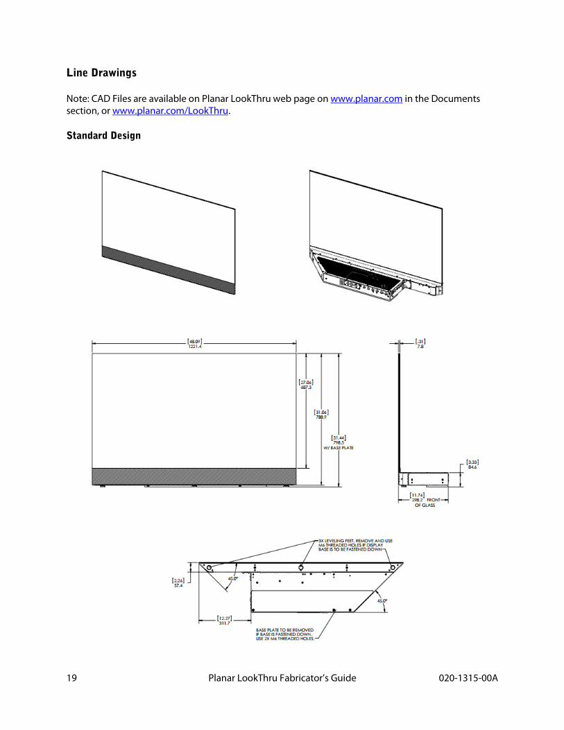
Line Drawings
Note: CAD Files are available on Planar LookThru web page on www.planar.com in the Documents section, or www.planar.com/LookThru.
Standard Design
20 Planar LookThru Fabricator’s Guide 020-1315-00A
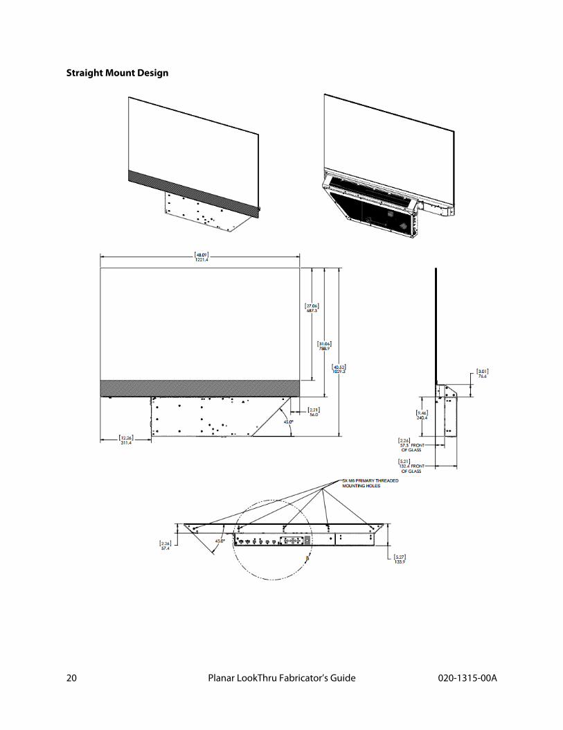
Straight Mount Design
21 Planar LookThru Fabricator’s Guide 020-1315-00A
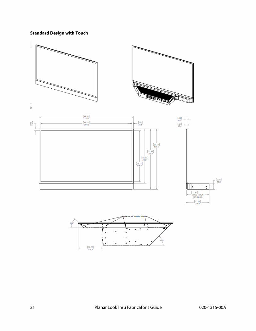
Standard Design with Touch
22 Planar LookThru Fabricator’s Guide 020-1315-00A
Straight Mount Design with Touch
23 Planar LookThru Fabricator’s Guide 020-1315-00A
Regulatory Information
Manufacturer's Name: Planar Systems, Inc.
Manufacturer's Address: 1195 NW Compton Drive
Beaverton, OR 97006
Note: This equipment has been tested and found to comply with the limits for a Class A digital device, pursuant to part 15 of the FCC Rules. These limits are designed to provide reasonable protection against harmful interference when the equipment is operated in a commercial environment. This equipment generates, uses, and can radiate radio frequency energy and, if not installed and used in accordance with the instruction manual, may cause harmful interference to radio communications. Operation of this equipment in a residential area is likely to cause harmful interference in which case the user will be required to correct the interference at his own expense.
Industry Canada (ICES-003): This Class A digital apparatus complies with Canadian ICES-003.
Cet appareil numérique de la classe A est conforme à la norme NMB-003 du Canada.
Any changes or modifications to the display not expressly approved by Planar could void the user's authority to operate this equipment.
Other Certifications:
CISPR 22