Embed Size (px)
Citation preview
PART 3
Simplified Wing Strut Analysis Of I Strut-Braced MonoplaneBrj Noel J. Becar, EAA 725
316 Del Rosa WaySan Mateo, Calif.
THIS REPORT is a continuation ofPart 2 in the December, 1959
issue of SPORT AVIATION, in thatit investigates design procedures forthe structural members analyzed forstresses in that report. The refer-ences consulted in the preparation ofthis paper are as follows:
No. 1—Stress Analysis of Commer-cial Aircraft (1928) by A. Klemin;
No. 2—Procedure Handbook f o rAircraft Stress Analysis (1940) byNye-Hamilton-Eames;
No. 3—ANC-5, Strength of MetalAircraft Elements (1955) by GPO.
No. 4—ANC-18, Design of WoodAircraft Structures (1951) by GPO.
No. 5—Airplane Structures, Vol. 1,3rd edition (1943) by Niles.Design of Lift Struts
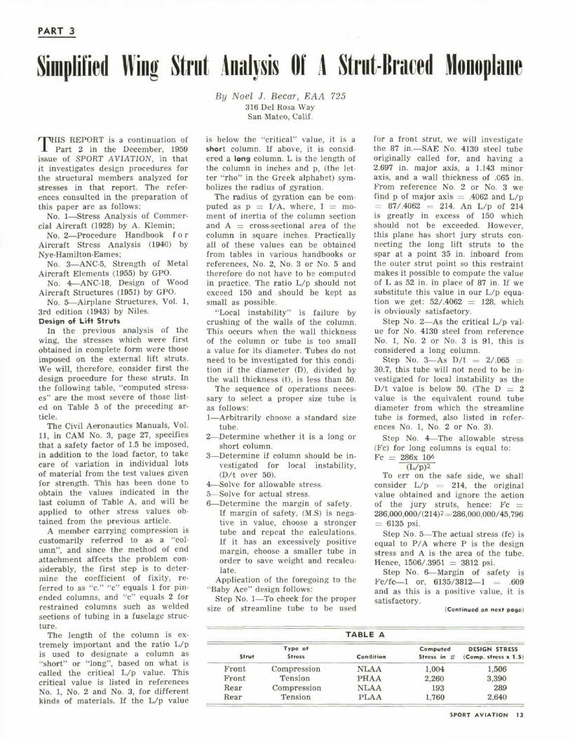
In the previous analysis of thewing, the stresses which were firstobtained in complete form were thoseimposed on the external lift struts.We will, therefore, consider first thedesign procedure for these struts. Inthe following table, "computed stress-es" are the most severe of those list-ed on Table 5 of the preceding ar-ticle.
The Civil Aeronautics Manuals, Vol.11, in CAM No. 3, page 27, specifiesthat a safety factor of 1.5 be imposed,in addition to the load factor, to takecare of variation in individual lotsof material from the test values givenfor strength. This has been done toobtain the values indicated in thelast column of Table A, and will beapplied to other stress values ob-tained from the previous article.
A member carrying compression iscustomarily referred to as a "col-umn", and since the method of endattachment affects the problem con-siderably, the first step is to deter-mine the coefficient of fixity, re-ferred to as "c." "c" equals 1 for pin-ended columns, and "c" equals 2 forrestrained columns such as weldedsections of tubing in a fuselage struc-ture.
The length of the column is ex-tremely important and the ratio L/pis used to designate a column as"short" or "long", based on what iscalled the critical L/p value. Thiscritical value is listed in referencesNo. 1, No. 2 and No. 3, for differentkinds of materials. If the L/p value
is below the "critical" value, it is ashort column. If above, it is consid-ered a long column. L is the length ofthe column in inches and p, (the let-ter "rho" in the Greek alphabet) sym-bolizes the radius of gyration.
The radius of gyration can be com-puted as p = I/A, where, I = mo-ment of inertia of the column sectionand A = cross-sectional area of thecolumn in square inches. Practicallyall of these values can be obtainedfrom tables in various handbooks orreferences, No. 2, No. 3 or No. 5 andtherefore do not have to be computedin practice. The ratio L/p should notexceed 150 and should be kept assmall as possible.
"Local instability" is failure bycrushing of the walls of the column.This occurs when the wall thicknessof the column or tube is too smalla value for its diameter. Tubes do notneed to be investigated for this condi-tion if the diameter (D), divided bythe wall thickness (t), is less than 50.
The sequence of operations neces-sary to select a proper size tube isas follows:1—Arbitrarily choose a standard size
tube.2—Determine whether it is a long or
short column.3—Determine if column should be in-
vestigated for local instability,(D/t over 50).
4—Solve for allowable stress.5—Solve for actual stress.6—Determine the margin of safety.
If margin of safety, (M.S) is nega-tive in value, choose a strongertube and repeat the calculations.If it has an excessively positivemargin, choose a smaller tube inorder to save weight and recalcu-late.
Application of the foregoing to the"Baby Ace" design follows:
Step No. 1—To check for the propersize of streamline tube to be used
for a front strut, we will investigatethe 87 in.—SAE No. 4130 steel tubeoriginally called for, and having a2.697 in. major axis, a 1.143 minoraxis, and a wall thickness of .065 in.From reference No. 2 or No. 3 wefind p of major axis = .4062 and L/p= 87/.4062 = 214. An L/p of 214is greatly in excess of 150 whichshould not be exceeded. However,this plane has short jury struts con-necting the long lift struts to thespar at a point 35 in. inboard fromthe outer strut point so this restraintmakes it possible to compute the valueof L as 52 in. in place of 87 in. If wesubstitute this value in our L/p equa-tion we get: 52/.4062 = 128, whichis obviously satisfactory.
Step No. 2—As the critical L/p val-ue for No. 4130 steel from referenceNo. 1, No. 2 or No. 3 is 91, this isconsidered a long column.
Step No. 3—As D/t = 2/.065 =30.7, this tube will not need to be in-vestigated for local instability as theD/t value is below 50. (The D = 2value is the equivalent round tubediameter from which the streamlinetube is formed, also listed in refer-ences No. 1, No. 2 or No. 3).
Step No. 4—The allowable stress(Fc) for long columns is equal to:Fc = 286x 1Q6
(L/p)2To err on the safe side, we shall
consider L/p =-_ 214, the originalvalue obtained and ignore the actionof the jury struts, hence: Fc =286,000,000/(214)2 = 286,000,000/45,796= 6135 psi.
Step No. 5—The actual stress (fc) isequal to P/A where P is the designstress and A is the area of the tube.Hence, 1506/.3951 = 3812 psi.
Step No. 6—Margin of safety isFc/fc—1 or, 6135/3812—1 = .609and as this is a positive value, it issatisfactory.
(Continued on next page)
TABLE A
Strut
FrontFrontRearRear
Typ« ofStress
CompressionTension
CompressionTension
Condition
NLAAPHAANLAAPLAA
ComputedStress in K
1,0042,260
1931,760
DESIGN STRESS(Comp. stress x 1.
1,5063,390
2892,640
S)
SPORT AVIATION 13
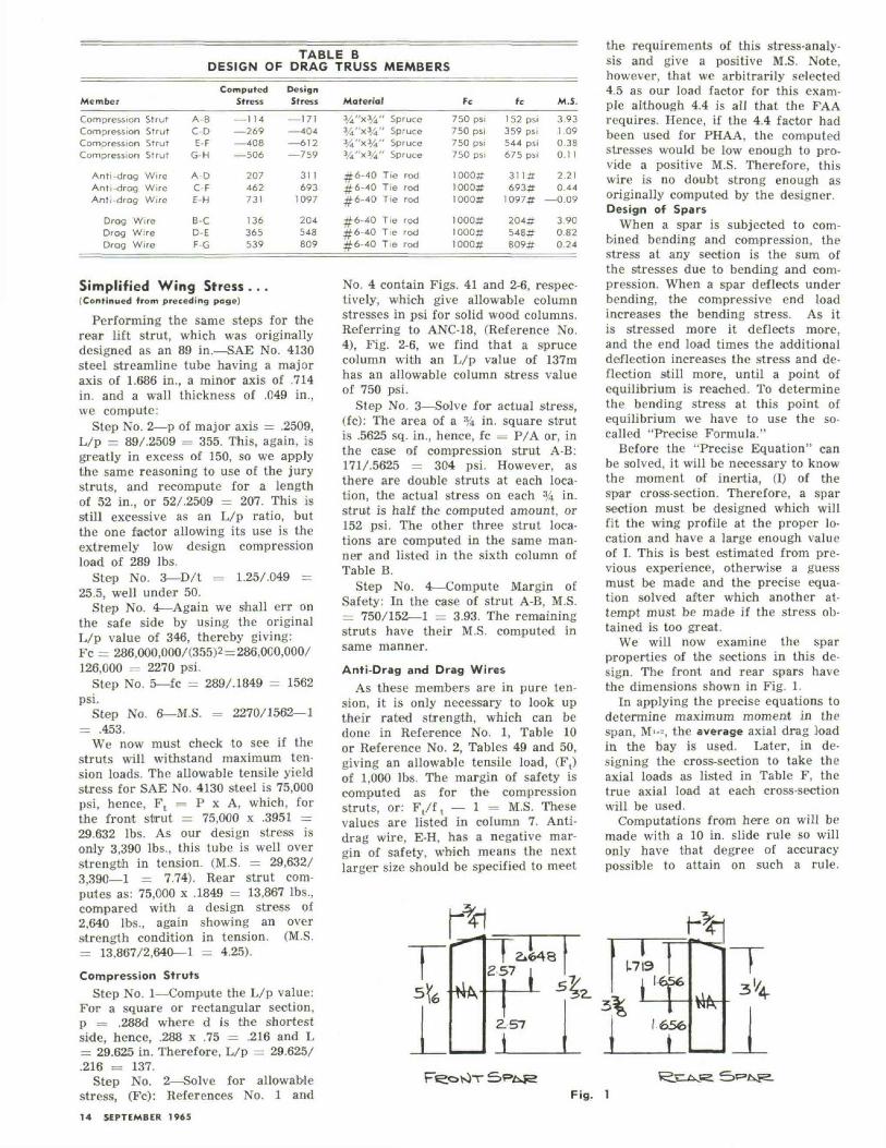
TABLE BDESIGN OF DRAG TRUSS MEMBERS
Member
Compression StrutCompression StrutCompression StrutCompression Strut
Anti-drog WireAnti-drag WireAnti-drag Wire
Drag WireDrag WireDrag Wire
ComputedStress
A-BC-DE-F
G-H
A-DC-FE-H
B-CD-EF-G
— 114—269— 408— 506
207462731
136365539
DesignStress
— 171— 404— 612—759
311693
1097
204548809
Material3/4"xy43/4"x3/43/4"x3/43/i"x%
#6-40#6-40#6-40
#6-40#6-40#6-40
" Spruce" Spruce" Spruce" Spruce
Tie rodTie rodTie rod
Tie rodTie rodTie rod
Fc
750 psi750 psi750 psi750 psi
1000#1000#1000#
1000#1000#1000#
fc
1 52 psi359 psi544 psi675 psi
311#693#
1097#
204*548#809*
M.S.
3.931.090.380.11
2.210.44
—0.09
3 900.820.24
Simplified Wing Stress ...(Continued from preceding page)
Performing the same steps for therear lift strut, which was originallydesigned as an 89 in.—SAE No. 4130steel streamline tube having a majoraxis of 1.686 in., a minor axis of .714in. and a wall thickness of .049 in.,we compute:
Step No. 2—p of major axis = .2509,L/p = 89/.2509 = 355. This, again, isgreatly in excess of 150, so we applythe same reasoning to use of the jurystruts, and recompute for a lengthof 52 in., or 52/.2509 = 207. This isstill excessive as an L/p ratio, butthe one factor allowing its use is theextremely low design compressionload of 289 lbs.
Step No. 3—D/t = 1.25/.049 =25.5, well under 50.
Step No. 4—Again we shall err onthe safe side by using the originalL/p value of 346, thereby giving:Fc = 286,000,000/(355)2 = 286,OCO,000/126,000 = 2270 psi.
Step No. 5—fc = 289/.1849 = 1562psi.
Step No. 6—M.S. = 2270/1562—1= .453.
We now must check to see if thestruts will withstand maximum ten-sion loads. The allowable tensile yieldstress for SAE No. 4130 steel is 75,000psi, hence, Ft = P x A, which, forthe front strut = 75,000 x .3951 =29.632 lbs. As our design stress isonly 3,390 lbs., this tube is well overstrength in tension. (M.S. = 29,632/3,390—1 = 7.74). Rear strut com-putes as: 75,000 x .1849 = 13,867 lbs.,compared with a design stress of2,640 lbs., again showing an overstrength condition in tension. (M.S.= 13,867/2,640—1 = 4.25).
Compression StrutsStep No. 1—Compute the L/p value:
For a square or rectangular section,p = .288d where d is the shortestside, hence, .288 x .75 = .216 and L= 29.625 in. Therefore, L/p = 29.62S/.216 = 137.
Step No. 2—Solve for allowablestress, (Fc): References No. 1 and
No. 4 contain Figs. 41 and 2-6, respec-tively, which give allowable columnstresses in psi for solid wood columns.Referring to ANC-18, (Reference No.4), Fig. 2-6, we find that a sprucecolumn with an L/p value of 137mhas an allowable column stress valueof 750 psi.
Step No. 3—Solve for actual stress,(fc): The area of a % in. square strutis .5625 sq. in., hence, fc = P/A or, inthe case of compression strut A-B:171/.5625 = 304 psi. However, asthere are double struts at each loca-tion, the actual stress on each % in.strut is half the computed amount, or152 psi. The other three strut loca-tions are computed in the same man-ner and listed in the sixth column ofTable B.
Step No. 4—Compute Margin ofSafety: In the case of strut A-B, M.S.= 750/152—1 = 3.93. The remainingstruts have their M.S. computed insame manner.
Anti-Drag and Drag WiresAs these members are in pure ten-
sion, it is only necessary to look uptheir rated strength, which can bedone in Reference No. 1, Table 10or Reference No. 2, Tables 49 and 50,giving an allowable tensile load, (F,)of 1,000 lbs. The margin of safety iscomputed as for the compressionstruts, or: F,/f, — 1 = M.S. Thesevalues are listed in column 7. Anti-drag wire, E-H, has a negative mar-gin of safety, which means the nextlarger size should be specified to meet
the requirements of this stress-analy-sis and give a positive M.S. Note,however, that we arbitrarily selected4.5 as our load factor for this exam-ple although 4.4 is all that the FAArequires. Hence, if the 4.4 factor hadbeen used for PHAA, the computedstresses would be low enough to pro-vide a positive M.S. Therefore, thiswire is no doubt strong enough asoriginally computed by the designer.Design of Spars
When a spar is subjected to com-bined bending and compression, thestress at any section is the sum ofthe stresses due to bending and com-pression. When a spar deflects underbending, the compressive end loadincreases the bending stress. As itis stressed more it deflects more,and the end load times the additionaldeflection increases the stress and de-flection still more, until a point ofequilibrium is reached. To determinethe bending stress at this point ofequilibrium we have to use the so-called "Precise Formula."
Before the "Precise Equation" canbe solved, it will be necessary to knowthe moment of inertia, (I) of thespar cross-section. Therefore, a sparsection must be designed which willfit the wing profile at the proper lo-cation and have a large enough valueof I. This is best estimated from pre-vious experience, otherwise a guessmust be made and the precise equa-tion solved after which another at-tempt must be made if the stress ob-tained is too great.
We will now examine the sparproperties of the sections in this de-sign. The front and rear spars havethe dimensions shown in Fig. 1.
In applying the precise equations todetermine maximum moment in thespan, M'--, the average axial drag loadin the bay is used. Later, in de-signing the cross-section to take theaxial loads as listed in Table F, thetrue axial load at each cross-sectionwill be used.
Computations from here on will bemade with a 10 in. slide rule so willonly have that degree of accuracypossible to attain on such a rule.
14 SEPTEMBER 1965
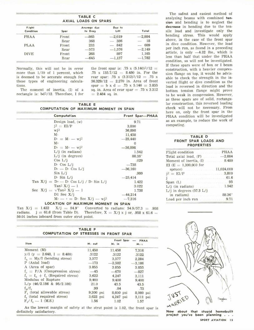
TABLE CAXIAL LOADS ON SPARS
FiightCondition
PHAA
PLAA
DIVE
Spar
FrontRear
FrontRear
FrontRear
Average dueto Drag
—865368233
—573268
—645
Due toLift
—2,019— 386— 842—1,576
897—1,137
Total
—2,884— 18— 609—2,149
1,165—1,782
Normally, this will not be in errormore than 1/10 of 1 percent, whichis deemed to be accurate enough forthese types of engineering calcula-tions.
The moment of inertia, (I) of arectangle is: bd3/12. Therefore, I for
the front spar is: .75 x (5.140)3/12 =.75 x 135.7/12 = 8.480 in. For therear spar: .75 x (3.312)3/12 = .75 x36.329/12 = 2.270 in. Area of frontspar = b x d = .75 x 5.140 = 3.855sq. in. Area of rear spar = .75 x 3.312= 2.484 sq. in.
TABLE ECOMPUTATION OF MAXIMUM MOMENT IN SPAN
Computation
Design load, (w)J2 = EI/Pwj2M-D' = M — wj2M«D- = M- — wj2L/j (in radians)L/j (in degrees)Cos L/jDI Cos L/jD- — D' Cos L/jSin L/jD' Sin L/j
Tan X/j = D= — D> Cos L/j / D> Sin L/jTan2 X/j — 1
Sec X/j = vTan2 X/j — 1Dl Sec X/jM' — * = DI Sec X/j — wj2
LOCATION OF MAXIMUM MOMENT IN SPANTan X/j = 1.422 X/j = 54.9° Converted to radians: 54.9/57.3 = .958radians, j = 61.6 (from Table D). Therefore, X = X/j x j or, .958 x 61.6 =59.01 inches inboard from outer strut point.
TABLE FCOMPUTATION OF STRESSES IN FRONT SPAR
Front Spar—PHAA
9.713,800
36,89811,458
—25,4400
—36,8981.542
88.36C
.029—738
—36,160.999
—25,4141.4223.0221.738
—44,214—7,316
Item Mi outFront Spar — PHAA
Mi in M,--..
Moment (M)y/I (y = 2.648, I = 8.480)fb = My/I (bending stress)P (Axial load)A (Area of spar)ft. = P/A (Compression stress)f t = fh + fc (Required stress)Modulus of RuptureL/p (46/2.186 & 95/2.186)V'tF, (total allowable stress)f t (total required stress)Ft/ f t — 1 (M.S.)
11,458.31223,577—1733.855—453,6229,400
21.0.99
9,300 psi3,622 psi
1.56
11,458.31223,577
—2,5823.855—6704,2479,40043.5
.848,600 psi4,247 psi
1.02
7,316.31222,284
—3,1863.855—8273,1119,40043.5
.738,000 psi3,111 psi
1.57As the lowest margin of safety at the strut point is 1.02, the front spar is
definitely satisfactory.
The safest and easiest method ofanalyzing beams with combined ten-sion and bending is to neglect thedecrease in bending due to the ten-sile load and investigate only thebending stress. This would applyabove, in the case of the front sparin dive condition. However, the loadper inch run, as found in a precedingarticle, is only —4.32 lbs., which isless than half that under the PHAAcondition, so will not be investigated.If these spars were of box or I beamconstruction, with a heavier compres-sion flange on top, it would be advis-able to check the strength in the in-verted flight or dive condition as theload is reversed in direction and thebottom tension flange might proveto be weak in compression. However,as these spars are of solid, rectangu-lar construction, this reversed loadingcheck will not be necessary. Fromhere on, only the front spar in thePHAA condition will be investigatedas an example, to reduce the work ofcomputing.
TABLE DFRONT SPAR LOADS AND
PROPERTIES________
Flight condition PHAATotal axial load, (P) . . . —2,884Moment of inertia, (I) . . . . . 8.480El (E - 1,300,OCO for
spruce) 11,024,000j2 = EI/P . . . . . . . . . . . . . . . . . 3,800j . . . . . . . . . . . . . . 61.6Span (L) . . . . . . . . . . . . 95L/j (in radians) 1.542L/j in degrees (57.3 L/j
i n radians) . . . . . . . 88.36°Load per inch run . . . . . . . . 9.71
Now about that stupid homebuiltproject you've been planning . . .
SPORT AVIATION 15