Embed Size (px)
Citation preview
Simplified Universal Nail S.U.N.Surgical Technique
Discontinued – December 2016;
AVAILABLE FOR IMPLANT REMOVAL
PURPOSES ONLY DSEM/TRM/1015/0536(2)

Image intensifier control
This description alone does not provide sufficient background for direct use of DePuy Synthes products. Instruction by a surgeon experienced in handling these products is highly recommended.
Processing, Reprocessing, Care and MaintenanceFor general guidelines, function control and dismantling of multi-part instruments, as well as processing guidelines for implants, please contact your local sales representative or refer to:http://emea.depuysynthes.com/hcp/reprocessing-care-maintenanceFor general information about reprocessing, care and maintenance of Synthes reusable devices, instrument trays and cases, as well as processing of Synthes non-sterile implants, please consult the Important Information leaflet (SE_023827) or refer to: http://emea.depuysynthes.com/hcp/reprocessing-care-maintenance

Simplified Universal Nail S.U.N. Surgical Technique DePuy Synthes 1
Table of Contents
AO Principles 3
Product Description 4
Use of the Image Intensifier 6
Surgical Technique – S.U.N. Tibia Indications and Contraindications 7
Positioning of the patient 8
Determining the point of insertion 9
Opening of the medullary cavity 10
Mounting the insertion instrument and aiming device 11
Insertion of the S.U.N. Tibia 12
Removal of the conical bolt 13
Distal locking 14
Proximal locking of the tibia 20
2 DePuy Synthes Simplified Universal Nail S.U.N. Surgical Technique
Table of Contents
Surgical Technique – S.U.N. Femur Indications and Contraindications 22
Positioning of the patient 23
Correct point of insertion 25
Opening of the medullary cavity 26
Mounting the insertion instrument and aiming device 28
Insertion of the S.U.N. Femur 29
Removal of the conical bolt 30
Distal Locking 31
Proximal Locking 32
Implant Removal Removal of the locking bolts 34
Loosening of a jammed conical bolt 36
Product Information Instruments 37
Implants 38
Simplified Universal Nails S.U.N. for Tibia 39
Simplified Universal Nails S.U.N. for Femur 40
MRI Information 41

1
4
2
3
4_Priciples_03.pdf 1 05.07.12 12:08
4 DePuy Synthes Expert Lateral Femoral Nail Surgical Technique
AO PRINCIPLES
In 1958, the AO formulated four basic principles, which have become the guidelines for internal fixation1, 2.
1 Müller ME, M Allgöwer, R Schneider, H Willenegger. Manual of Internal Fixation. 3rd ed. Berlin Heidelberg New York: Springer. 1991.
2 Rüedi TP, RE Buckley, CG Moran. AO Principles of Fracture Management. 2nd ed. Stuttgart, New York: Thieme. 2007.
Anatomic reductionFracture reduction and fixation to restore anatomical relationships.
Early, active mobilizationEarly and safe mobilization and rehabilitation of the injured part and the patient as a whole.
Stable fixationFracture fixation providing abso-lute or relative stability, as required by the patient, the injury, and the personality of the fracture.
Preservation of blood supplyPreservation of the blood supply to soft tissues and bone by gentle reduction techniques and careful handling.
Simplified Universal Nail S.U.N. Surgical Technique DePuy Synthes 3
AO Principles
In 1958, the AO formulated four basic principles, which have become the guidelines for internal fixation1,2.
Anatomic reductionFracture reduction and fixation to restore anatomical relationships.
Early, active mobilizationEarly and safe mobilization and rehabilitation of the injured part and the patient as a whole.
Stable fixationFracture fixation providing absolute or relative stability, as required by the patient, the injury, and the per-sonality of the fracture.
Preservation of blood supplyPreservation of the blood supply to soft tissues and bone by gentle reduction techniques and careful handling.
1 Müller ME, Allgöwer M, Schneider R, Willenegger H. Manual of Internal Fixation. 3rd ed. Berlin, Heidelberg, New York: Springer. 1991.
2 Rüedi TP, Buckley RE, Moran CG. AO Principles of Fracture Management. 2nd ed. Stuttgart, New York: Thieme. 2007.

4 DePuy Synthes Simplified Universal Nail S.U.N. Surgical Technique
Product Description
Tibia and FemurOptimal load transmission during insertion and extrac-tion of the nail due to the special thread design. The constant diameter of the thread allows the same instru-ments to be used for all nail diameters in the tibia, whereas different insertion instruments are applied in the femur depending on the nail diameter.
Right and left application made possible by the trans-verse locking bolt feature.
Proximal Locking: Choice of two round holes for static locking (only one hole for femur) secures the rotational and axial stability. A dynamic hole allows axial suitable dynamisation.
Wall thickness of 1.25 mm causes as a closed tube on a feasible stability.
Anatomical designTibia: The AO/ASIF curvature of 11° in the upper third of the S.U.N. facilitates insertion and good ana tomical fit.Femur: The 1.5-m radius of the S.U.N. corresponds closely with the average anatomical curvature of the femur.
Secure distal locking through two medial/lateral holes. Fe
murTi
bia
12
3
Simplified Universal Nail S.U.N. Surgical Technique DePuy Synthes 1
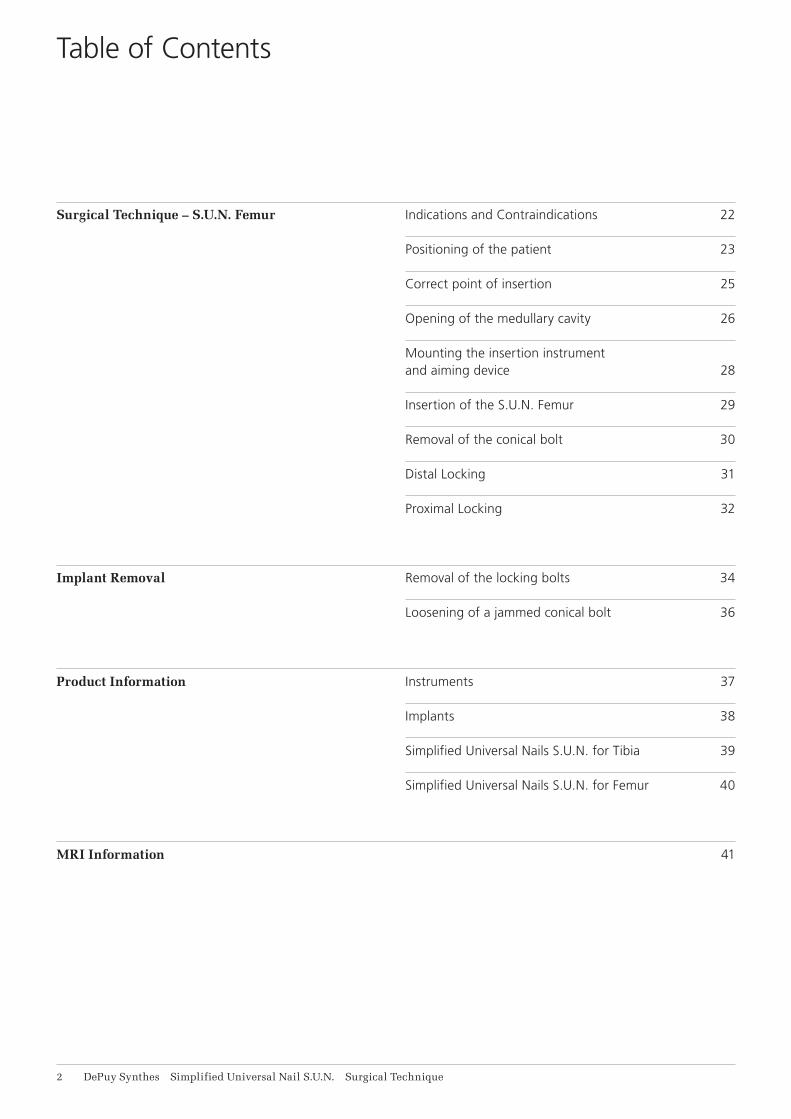
Looking bolts
Locking• High strength (4.3 mm core diameter)• No tapping necessary• A facilitated locking technique
4.9 mm Locking Bolt features:• One diameter bolt for all applications using universal
nails• 4.9 mm thread diameter, engages bone and nail for
superior holding capacity• Fully-threaded shaft for easier insertion and extraction • 4.3 mm core diameter for greater strength• Low head profi le for areas with minimal soft tissue
coverage• Self-cutting trocar tip to eliminate tapping
Product Description
AA
6 DePuy Synthes Simplified Universal Nail S.U.N. Surgical Technique
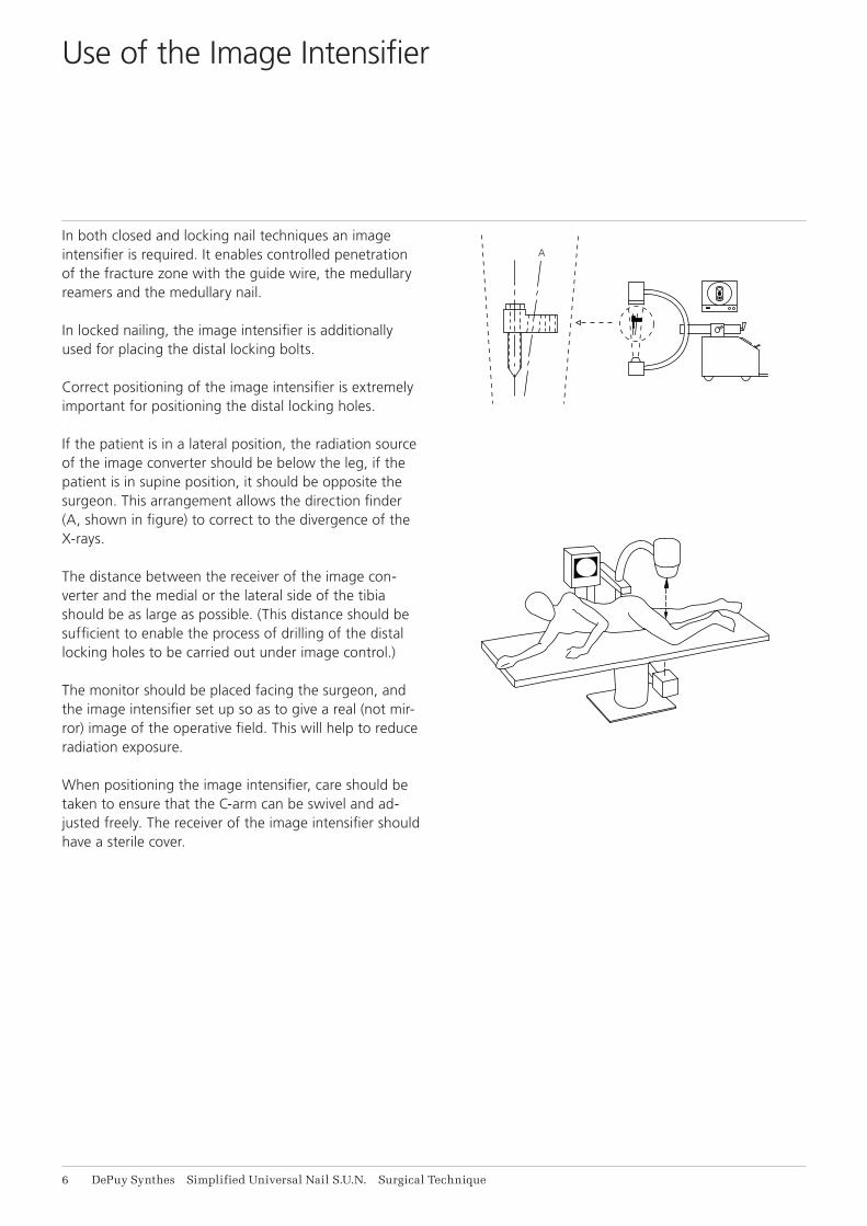
In both closed and locking nail techniques an image intensifier is required. It enables controlled penetration of the fracture zone with the guide wire, the medullary reamers and the medullary nail.
In locked nailing, the image intensifier is additionally used for placing the distal locking bolts.
Correct positioning of the image intensifier is extremely important for positioning the distal locking holes.
If the patient is in a lateral position, the radiation source of the image converter should be below the leg, if the patient is in supine position, it should be opposite the surgeon. This arrangement allows the direction finder (A, shown in figure) to correct to the divergence of the X-rays.
The distance between the receiver of the image con-verter and the medial or the lateral side of the tibia should be as large as possible. (This distance should be sufficient to enable the process of drilling of the distal locking holes to be carried out under image control.)
The monitor should be placed facing the surgeon, and the image intensifier set up so as to give a real (not mir-ror) image of the operative field. This will help to reduce radiation exposure.
When positioning the image intensifier, care should be taken to ensure that the C-arm can be swivel and ad-justed freely. The receiver of the image intensifier should have a sterile cover.
Use of the Image Intensifier

60%
20%
20%
Simplified Universal Nail S.U.N. Surgical Technique DePuy Synthes 7
Indications:Fractures with bony support (stable fracture in the middle third of the tibia)
1. transverse fractures2. short oblique fractures3. pseudarthrosis
Fractures without bony support (unstable fractures in 60% of the tibial length)
4. fractures near the metaphysis5. long torsional fractures6. segmental fractures7. comminuted fractures8. fractures with bone defects
The S.U.N. must be locked with locking bolts to achieve rotational and axial stability of the fracture.
Contraindications:No specific Contrainidications
Surgical Technique – S.U.N. Tibia
Indications and Contraindications
8 DePuy Synthes Simplified Universal Nail S.U.N. Surgical Technique
Surgical Technique – S.U.N. Tibia
Positioning of the patient
The reduction of the fracture can be carried out using open or closed techniques. For open reduction, the fracture must be exposed. Closed reduction is carried out by means of an extension table under image intensi-fication and is preferable to open reduction. For both techniques, the large distractor can be used to facilitate reduction (see product information on the “Large Distractor”).
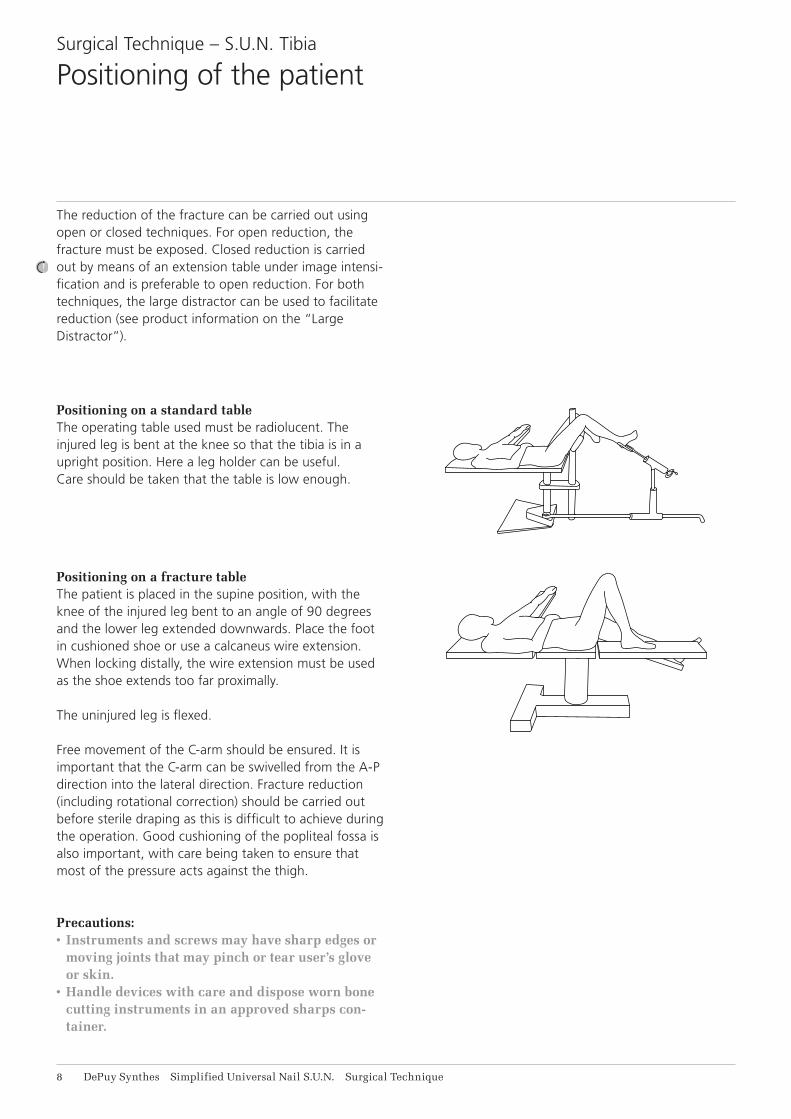
Positioning on a standard tableThe operating table used must be radiolucent. The injured leg is bent at the knee so that the tibia is in a upright position. Here a leg holder can be useful. Care should be taken that the table is low enough.
Positioning on a fracture tableThe patient is placed in the supine position, with the knee of the injured leg bent to an angle of 90 degrees and the lower leg extended downwards. Place the foot in cushioned shoe or use a calcaneus wire extension. When locking distally, the wire extension must be used as the shoe extends too far proximally.
The uninjured leg is flexed.
Free movement of the C-arm should be ensured. It is important that the C-arm can be swivelled from the A-P direction into the lateral direction. Fracture reduction (including rotational correction) should be carried out before sterile draping as this is difficult to achieve during the operation. Good cushioning of the popliteal fossa is also important, with care being taken to ensure that most of the pressure acts against the thigh.
Precautions:• Instruments and screws may have sharp edges or
moving joints that may pinch or tear user’s glove or skin.
• Handle devices with care and dispose worn bone cutting instruments in an approved sharps con-tainer.

ML
P
A
Simplified Universal Nail S.U.N. Surgical Technique DePuy Synthes 9
Correct siting of the insertion point of the nail is impor-tant if a trouble-free introduction of the nail is to be ensured.
The insertion point should be sited as far as proximally possible but on no account in the knee joint.
It is important that the site of entry is aligned directly with the centre of the medullary cavity, i.e., slightly medial to the tibial tuberosity.
Surgical Technique – S.U.N. Tibia
Determining the point of insertion
11 DePuy Synthes Simplified Universal Nail S.U.N. Surgical Technique
Surgical Technique – S.U.N. Tibia
Opening of the medullary cavity
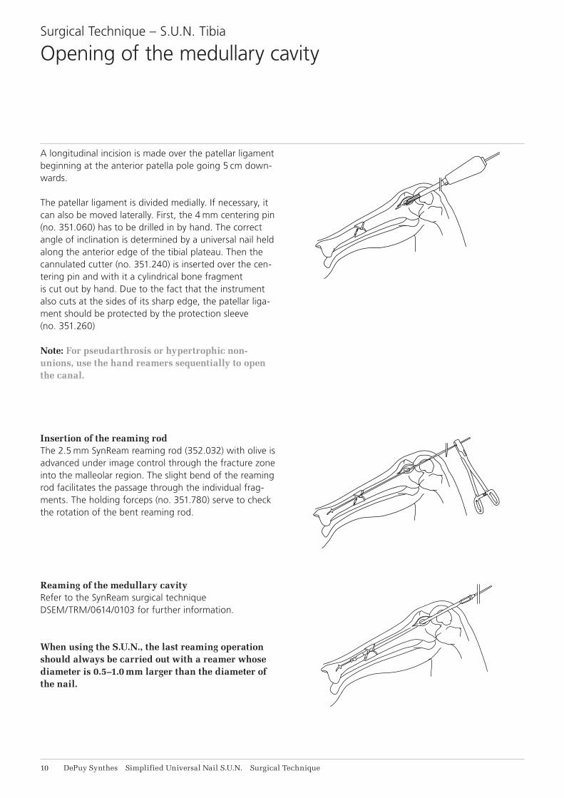
A longitudinal incision is made over the patellar ligament beginning at the anterior patella pole going 5 cm down-wards.
The patellar ligament is divided medially. If necessary, it can also be moved laterally. First, the 4 mm centering pin (no. 351.060) has to be drilled in by hand. The correct angle of inclination is determined by a universal nail held along the anterior edge of the tibial plateau. Then the cannulated cutter (no. 351.240) is inserted over the cen-tering pin and with it a cylindrical bone fragment is cut out by hand. Due to the fact that the instrument also cuts at the sides of its sharp edge, the patellar liga-ment should be protected by the protection sleeve (no. 351.260)
Note: For pseudarthrosis or hypertrophic non-unions, use the hand reamers sequentially to open the canal.
Insertion of the reaming rodThe 2.5 mm SynReam reaming rod (352.032) with olive is advanced under image control through the fracture zone into the malleolar region. The slight bend of the reaming rod facilitates the passage through the individual frag-ments. The holding forceps (no. 351.780) serve to check the rotation of the bent reaming rod.
Reaming of the medullary cavityRefer to the SynReam surgical technique DSEM/TRM/0614/0103 for further information.
When using the S.U.N., the last reaming operation should always be carried out with a reamer whose diameter is 0.5–1.0 mm larger than the diameter of the nail.
2–3 mm
E
A
C
B
D
F
DYNAM.
TIBIA 9–14
C
BA
Simplified Universal Nail S.U.N. Surgical Technique DePuy Synthes 11
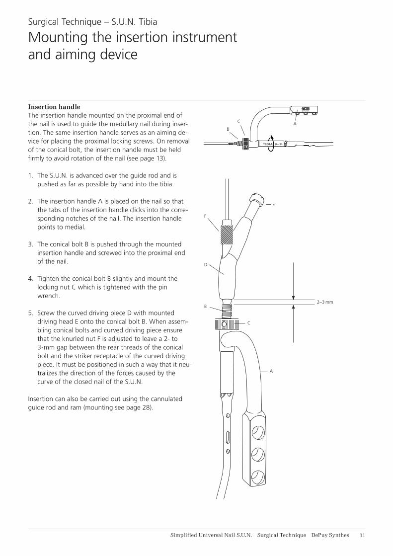
Insertion handleThe insertion handle mounted on the proximal end of the nail is used to guide the medullary nail during inser-tion. The same insertion handle serves as an aiming de-vice for placing the proximal locking screws. On removal of the conical bolt, the insertion handle must be held firmly to avoid rotation of the nail (see page 13).
1. The S.U.N. is advanced over the guide rod and is pushed as far as possible by hand into the tibia.
2. The insertion handle A is placed on the nail so that the tabs of the insertion handle clicks into the corre-sponding notches of the nail. The insertion handle points to medial.
3. The conical bolt B is pushed through the mounted insertion handle and screwed into the proximal end of the nail.
4. Tighten the conical bolt B slightly and mount the locking nut C which is tightened with the pin wrench.
5. Screw the curved driving piece D with mounted driving head E onto the conical bolt B. When assem-bling conical bolts and curved driving piece ensure that the knurled nut F is adjusted to leave a 2- to 3-mm gap between the rear threads of the conical bolt and the striker receptacle of the curved driving piece. It must be positioned in such a way that it neu-tralizes the direction of the forces caused by the curve of the closed nail of the S.U.N.
Insertion can also be carried out using the cannulated guide rod and ram (mounting see page 28).
Surgical Technique – S.U.N. Tibia
Mounting the insertion instrument and aiming device
TIBIA 9–14
DYNAM.
12 DePuy Synthes Simplified Universal Nail S.U.N. Surgical Technique
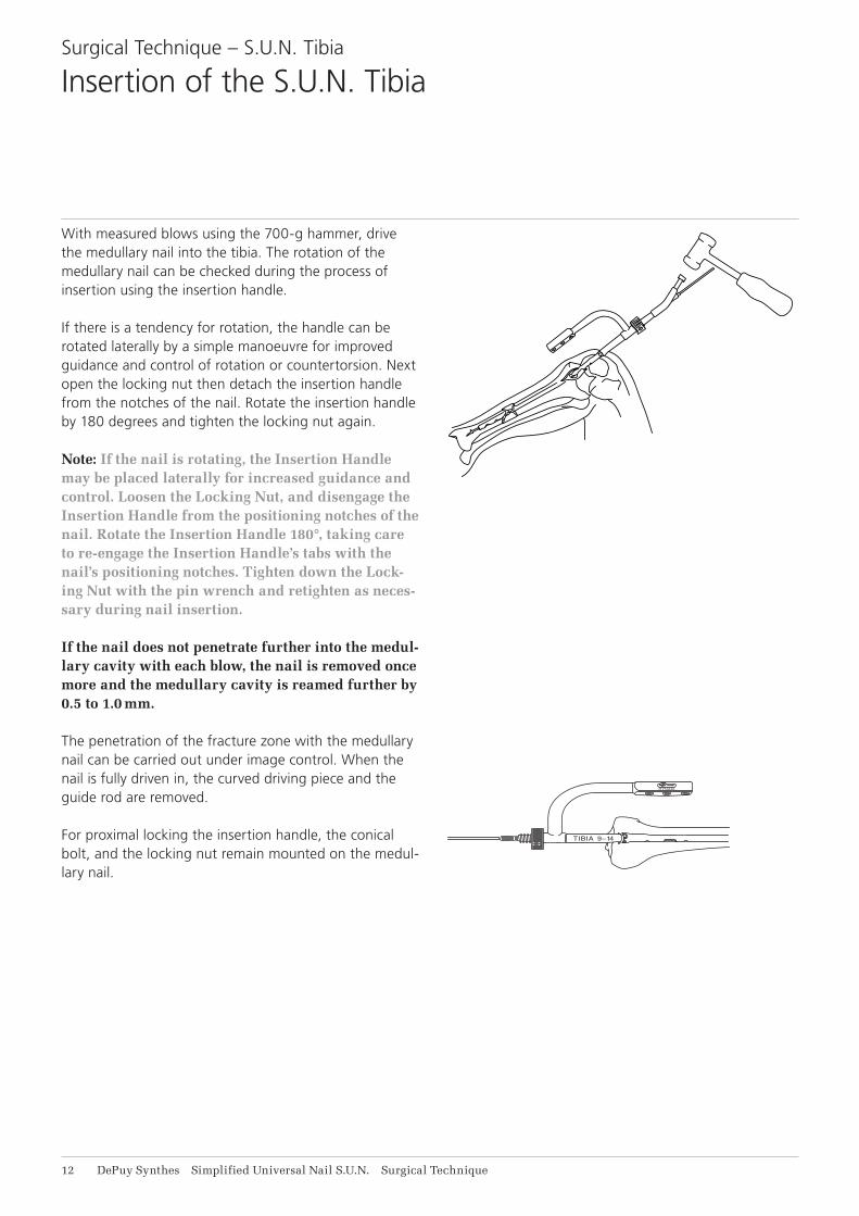
With measured blows using the 700-g hammer, drive the medullary nail into the tibia. The rotation of the medullary nail can be checked during the process of insertion using the insertion handle.
If there is a tendency for rotation, the handle can be rotated laterally by a simple manoeuvre for improved guidance and control of rotation or countertorsion. Next open the locking nut then detach the insertion handle from the notches of the nail. Rotate the insertion handle by 180 degrees and tighten the locking nut again.
Note: If the nail is rotating, the Insertion Handle may be placed laterally for increased guidance and control. Loosen the Locking Nut, and disengage the Insertion Handle from the positioning notches of the nail. Rotate the Insertion Handle 180°, taking care to re-engage the Insertion Handle’s tabs with the nail’s positioning notches. Tighten down the Lock-ing Nut with the pin wrench and retighten as neces-sary during nail insertion.
If the nail does not penetrate further into the medul-lary cavity with each blow, the nail is removed once more and the medullary cavity is reamed further by 0.5 to 1.0 mm.
The penetration of the fracture zone with the medullary nail can be carried out under image control. When the nail is fully driven in, the curved driving piece and the guide rod are removed.
For proximal locking the insertion handle, the conical bolt, and the locking nut remain mounted on the medul-lary nail.
Surgical Technique – S.U.N. Tibia
Insertion of the S.U.N. Tibia

DY
NA
M.
TIB
IA 9
–14
X
M
A
M
C
B
X
Simplified Universal Nail S.U.N. Surgical Technique DePuy Synthes 13
1. Loosen the nut C by half a turn.2. Hold the insertion handle A firmly … 3. … and detach the conical bolt B with the combina-
tion wrench or socket wrench.
Non-observance of this instruction can lead to a cross-threading of the conical bolt in the nail.
Any attempt to remove the conical bolt by force can lead to a total jamming of the bolt. Should jamming occur, loosen the conical bolt with the combination wrench and locking pliers (see also page 36).
If the insertion handle is used to resist the torque on removal of the conical bolt, jamming can be prevented.
The tabs of the handle articulate with the notches of the proximal end of the medullary nail, and thus prevent dis-tortion of the nail. The conical bolt can thus be removed without any problems.
Key:M = Removal moment of the conical boltX = Resisting moment through the insertion handle
Surgical Technique – S.U.N. Tibia
Removal of the conical bolt

14 DePuy Synthes Simplified Universal Nail S.U.N. Surgical Technique
1. Position the image intensifier as far as the X-ray axis corresponds to the hole axis of the locking hole.
The positioning is carried out at the proximal hole of the two distal locking holes unless this hole is too near to the fracture. This position is achieved by swivelling and tilting the C-arm.
The image must be congruent with the surgical field as seen by the surgeon, i.e., the right hole in the sur-gical field must also be the right hole on the screen.
When the two axes correspond, the locking hole will ap-pear completely round on the screen. At this adjustment the proximal hole should be positioned in the middle of the lower half of the screen.
2. The cutaneous incision is carried out under image control. Place an incision about 4 cm long over the two distal holes down to the bone surface.
Surgical Technique – S.U.N. Tibia
Distal locking

Simplified Universal Nail S.U.N. Surgical Technique DePuy Synthes 11
Dot of aiming trocar
Direction finder
3. The distal aiming device, with inserted aiming trocar (no. 355.640), is pushed through the incision onto the bone surface.
4. Slightly tilt the distal aiming device under image intensification as far as the dot is in the centre of the circle of the direction finder.
Without changing direction, the distal aiming device is moved over the bone surface up to the dot of the aim-ing trocar appearing in the centre of the locking hole.
The direction finder keeps the protection sleeve of the distal aiming device aligned with the beam axis.
Surgical Technique – S.U.N. TibiaDistal locking
16 DePuy Synthes Simplified Universal Nail S.U.N. Surgical Technique
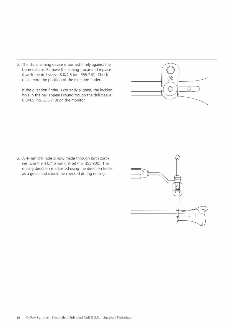
5. The distal aiming device is pushed firmly against the bone surface. Remove the aiming trocar and replace it with the drill sleeve 8.0/4.5 (no. 355.710). Check once more the position of the direction finder. If the direction finder is correctly aligned, the locking hole in the nail appears round trough the drill sleeve 8.0/4.5 (no. 335.710) on the monitor.
6. A 4-mm drill hole is now made through both corti-ces. Use the 4.0/4.5 mm drill bit (no. 355.900). The drilling direction is adjusted using the direction finder as a guide and should be checked during drilling.
Simplified Universal Nail S.U.N. Surgical Technique DePuy Synthes 17
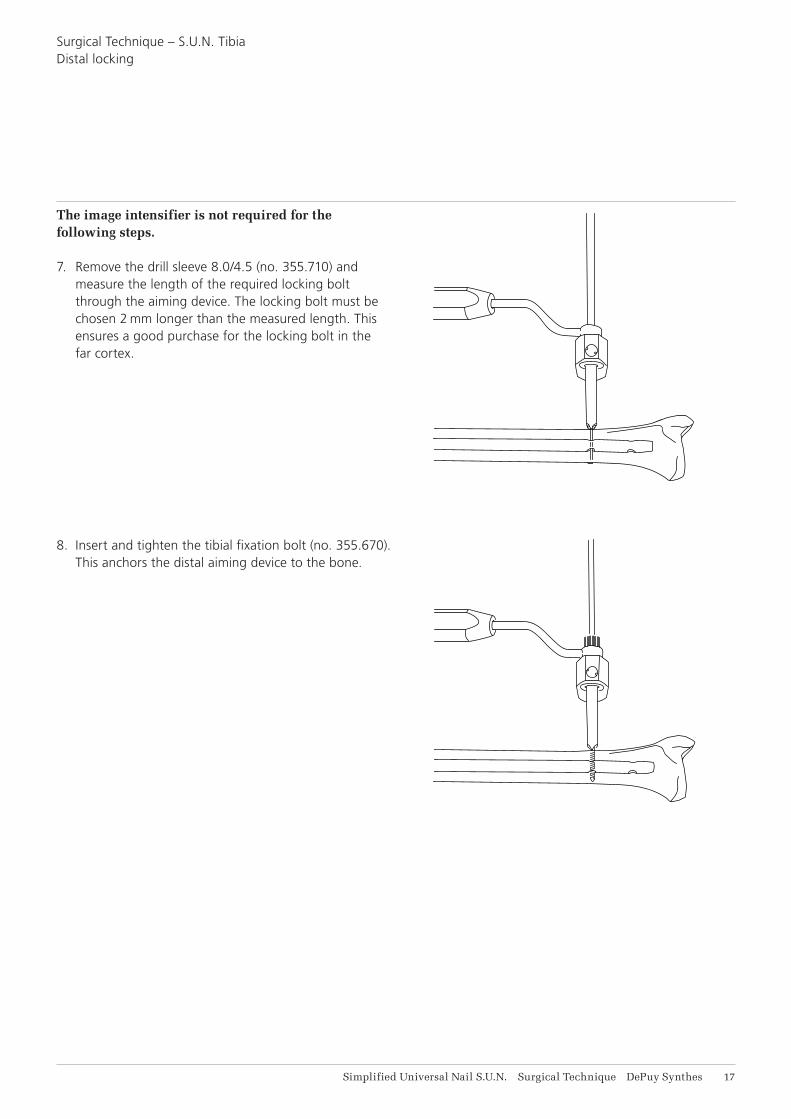
The image intensifier is not required for the following steps.
7. Remove the drill sleeve 8.0/4.5 (no. 355.710) and measure the length of the required locking bolt through the aiming device. The locking bolt must be chosen 2 mm longer than the measured length. This ensures a good purchase for the locking bolt in the far cortex.
8. Insert and tighten the tibial fixation bolt (no. 355.670). This anchors the distal aiming device to the bone.
Surgical Technique – S.U.N. TibiaDistal locking
18 DePuy Synthes Simplified Universal Nail S.U.N. Surgical Technique
metal guide
Screwdriver
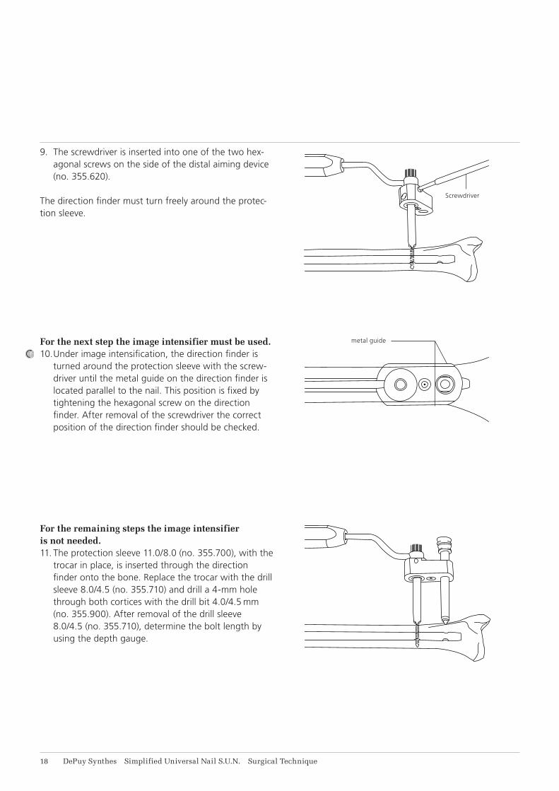
9. The screwdriver is inserted into one of the two hex-agonal screws on the side of the distal aiming device (no. 355.620).
The direction finder must turn freely around the protec-tion sleeve.
For the next step the image intensifier must be used.10. Under image intensification, the direction finder is
turned around the protection sleeve with the screw-driver until the metal guide on the direction finder is located parallel to the nail. This position is fixed by tightening the hexagonal screw on the direction finder. After removal of the screwdriver the correct position of the direction finder should be checked.
For the remaining steps the image intensifier is not needed.11. The protection sleeve 11.0/8.0 (no. 355.700), with the
trocar in place, is inserted through the direction finder onto the bone. Replace the trocar with the drill sleeve 8.0/4.5 (no. 355.710) and drill a 4-mm hole through both cortices with the drill bit 4.0/4.5 mm (no. 355.900). After removal of the drill sleeve 8.0/4.5 (no. 355.710), determine the bolt length by using the depth gauge.
Simplified Universal Nail S.U.N. Surgical Technique DePuy Synthes 19
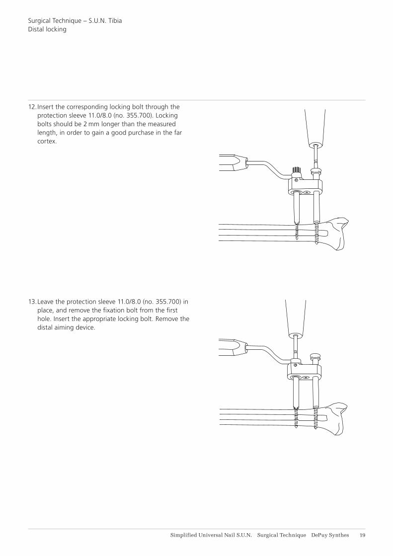
12. Insert the corresponding locking bolt through the protection sleeve 11.0/8.0 (no. 355.700). Locking bolts should be 2 mm longer than the measured length, in order to gain a good purchase in the far cortex.
13. Leave the protection sleeve 11.0/8.0 (no. 355.700) in place, and remove the fixation bolt from the first hole. Insert the appropriate locking bolt. Remove the distal aiming device.
Surgical Technique – S.U.N. TibiaDistal locking
TIBIA 9–14
DYNAM.
DYNAM.
TIBIA 9–14
DYNAM.
TIBIA 9–14
DYNAM.
TIBIA 9–14
DYNAM.
TIBIA 9–14
21 DePuy Synthes Simplified Universal Nail S.U.N. Surgical Technique
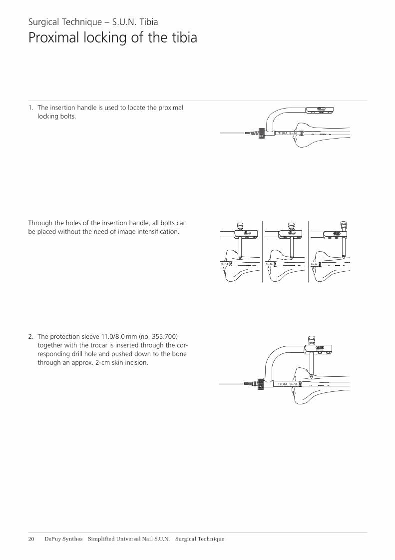
2. The protection sleeve 11.0/8.0 mm (no. 355.700) together with the trocar is inserted through the cor-responding drill hole and pushed down to the bone through an approx. 2-cm skin incision.
1. The insertion handle is used to locate the proximal locking bolts.
Through the holes of the insertion handle, all bolts can be placed without the need of image intensification.
Surgical Technique – S.U.N. Tibia
Proximal locking of the tibia
DYNAM.
TIBIA 9–14
DYNAM.
TIBIA 9–14
DYNAM.
TIBIA 9–14
Simplified Universal Nail S.U.N. Surgical Technique DePuy Synthes 21
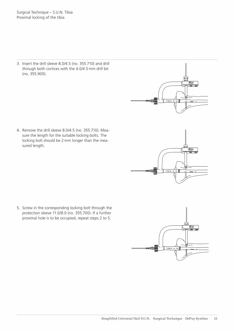
3. Insert the drill sleeve 8.0/4.5 (no. 355.710) and drill through both cortices with the 4.0/4.5 mm drill bit (no. 355.900).
Surgical Technique – S.U.N. TibiaProximal locking of the tibia
4. Remove the drill sleeve 8.0/4.5 (no. 355.710). Mea-sure the length for the suitable locking bolts. The locking bolt should be 2 mm longer than the mea-sured length.
5. Screw in the corresponding locking bolt through the protection sleeve 11.0/8.0 (no. 355.700). If a further proximal hole is to be occupied, repeat steps 2 to 5.

20%
20%
60%
22 DePuy Synthes Simplified Universal Nail S.U.N. Surgical Technique
Indications:Fractures with bony support (stable fracture in the middle third of the femur)
1. transverse fractures2. short oblique fractures3. pseudarthrosis
Fractures without bony support (unstable fracture in 60% of the femoral length)
4. fractures near the metaphysis5. long torsional fractures6. segmental fractures7. comminuted fractures8. fractures with bone defects
The S.U.N. must be locked with locking bolts to achieve rotational and axial stability of the fracture.
Contraindications:No specific contraindications
Surgical Technique – S.U.N. Femur
Indications and Contraindications

Simplified Universal Nail S.U.N. Surgical Technique DePuy Synthes 23
Surgical Technique – S.U.N. Femur
Positioning of the patient
Reduction of the fracture may be carried out using open or closed techniques.
Closed reduction must be carried out under image con-trol. This technique is preferable to open reduction.
The large distractor may also be used for both tech-niques (see product information on the large distractor).
Medullary nailing can be performed with the patient in the supine or lateral position.
Lateral positioning on fracture tableA fracture table with long cantilevers is used. The patient is placed in a lateral decubitus position. The pelvis is held exactly vertical by pelvic supports on both sides of the table. The patient is slid downwards on the table until the perineum rests on a well cushioned perineal post. In male patients check that the genitals are freely mobile.
Supine positioning on fracture tableWith the patient in the supine position, the leg of the injured femur is allowed to hang with the knee fixed 90 degrees. The patient’s pelvis should lie flat on the table to ensure the correct rotational alignment of the femur. Rotation cannot be corrected. If possible, slightly adduct the injured leg at the hip.
24 DePuy Synthes Simplified Universal Nail S.U.N. Surgical Technique
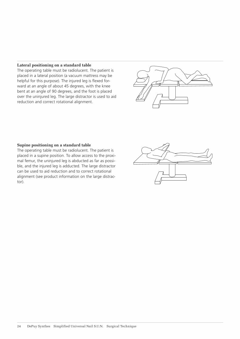
Lateral positioning on a standard tableThe operating table must be radiolucent. The patient is placed in a lateral position (a vacuum mattress may be helpful for this purpose). The injured leg is flexed for-ward at an angle of about 45 degrees, with the knee bent at an angle of 90 degrees, and the foot is placed over the uninjured leg. The large distractor is used to aid reduction and correct rotational alignment.
Supine positioning on a standard tableThe operating table must be radiolucent. The patient is placed in a supine position. To allow access to the proxi-mal femur, the uninjured leg is abducted as far as possi-ble, and the injured leg is adducted. The large distractor can be used to aid reduction and to correct rotational alignment (see product information on the large distrac-tor).

M
A
L
P
Simplified Universal Nail S.U.N. Surgical Technique DePuy Synthes 21
The choice of the correct point of insertion is important in use of the S.U.N.
Investigations on the geometry of the medullary cavity have shown that the ideal point of insertion for the Simplified Universal Nail S.U.N. is directly in the piriform fossa. Rotation of the S.U.N. is thus prevented.
Surgical Technique – S.U.N. Femur
Correct point of insertion
26 DePuy Synthes Simplified Universal Nail S.U.N. Surgical Technique
Surgical Technique – S.U.N. Femur
Opening of the medullary cavity
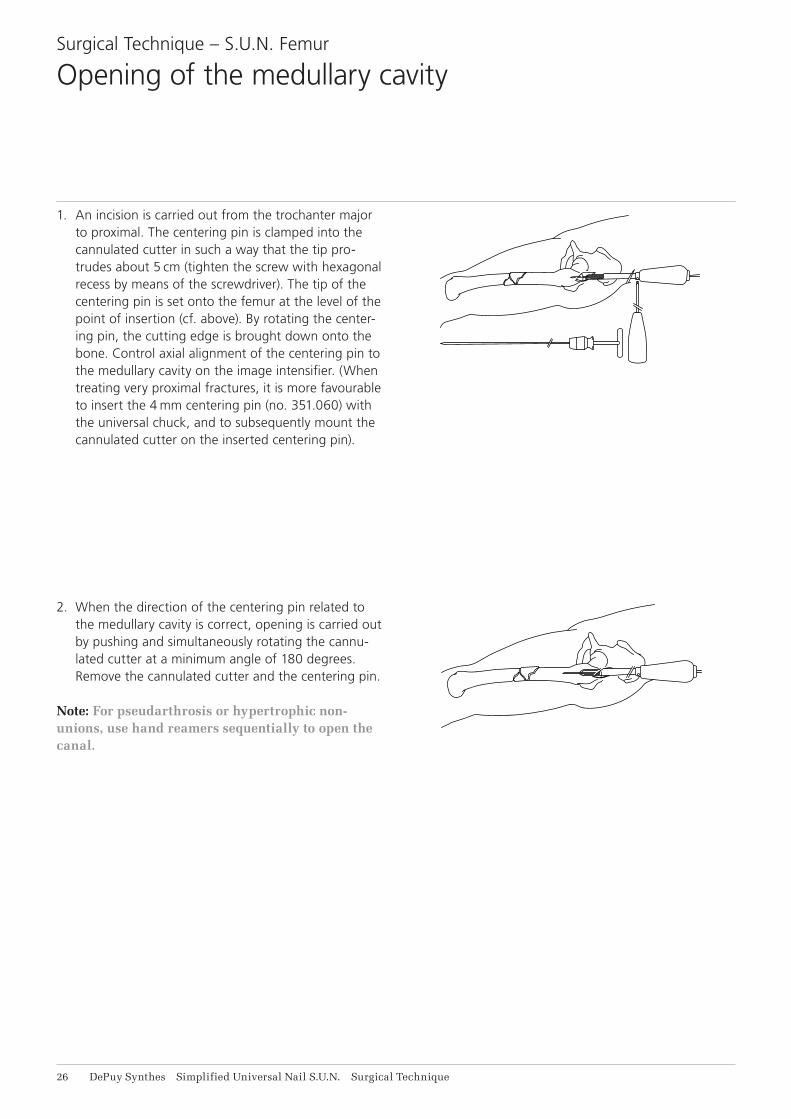
1. An incision is carried out from the trochanter major to proximal. The centering pin is clamped into the cannulated cutter in such a way that the tip pro-trudes about 5 cm (tighten the screw with hexagonal recess by means of the screwdriver). The tip of the centering pin is set onto the femur at the level of the point of insertion (cf. above). By rotating the center-ing pin, the cutting edge is brought down onto the bone. Control axial alignment of the centering pin to the medullary cavity on the image intensifier. (When treating very proximal fractures, it is more favourable to insert the 4 mm centering pin (no. 351.060) with the universal chuck, and to subsequently mount the cannulated cutter on the inserted centering pin).
2. When the direction of the centering pin related to the medullary cavity is correct, opening is carried out by pushing and simultaneously rotating the cannu-lated cutter at a minimum angle of 180 degrees. Remove the cannulated cutter and the centering pin.
Note: For pseudarthrosis or hypertrophic non-unions, use hand reamers sequentially to open the canal.
Simplified Universal Nail S.U.N. Surgical Technique DePuy Synthes 27
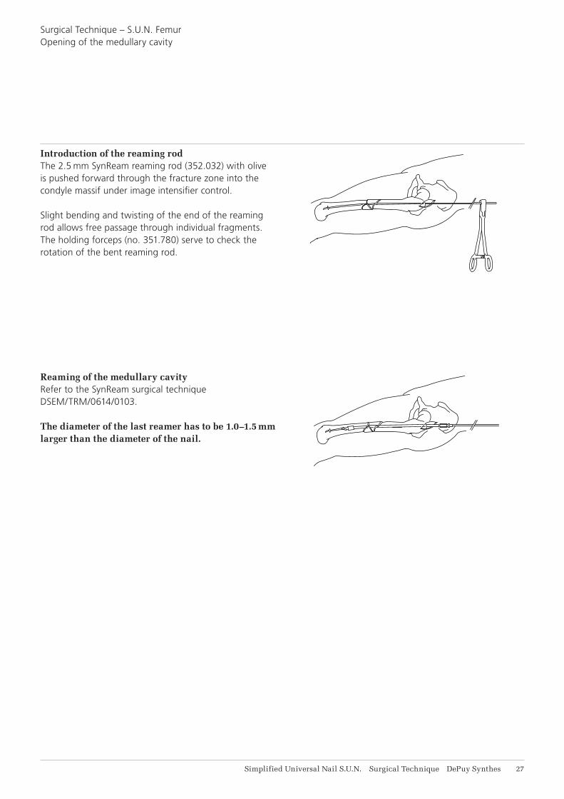
Introduction of the reaming rodThe 2.5 mm SynReam reaming rod (352.032) with olive is pushed forward through the fracture zone into the condyle massif under image intensifier control.
Slight bending and twisting of the end of the reaming rod allows free passage through individual fragments. The holding forceps (no. 351.780) serve to check the rotation of the bent reaming rod.
Reaming of the medullary cavityRefer to the SynReam surgical technique DSEM/TRM/0614/0103.
The diameter of the last reamer has to be 1.0–1.5 mm larger than the diameter of the nail.
Surgical Technique – S.U.N. FemurOpening of the medullary cavity

DYNAM.
FEMUR 9–12
STAT.
DY
NA
M.
FE
MU
R 9
–12
STA
T.
B
C
DA
28 DePuy Synthes Simplified Universal Nail S.U.N. Surgical Technique
The insertion handle mounted on the proximal end of the nail serves to guide the medullary nail during insertion.
The same insertion handle serves as an aiming device for placing the proximal locking bolts.
For the removal of the conical bolt, the insertion handle must be used as a counter stay (see page 30).
1. The S.U.N. is passed over the guide rod and pushed by hand as far as possible into the femur.
2. The conical bolt B is screwed into the proximal end of the nail, and the insertion handle A is mounted.
3. Tighten the conical bolt B with the combination wrench and apply the locking nut C which is then tightened with the pin wrench.
4. Push the cannulated guide rod (no. 355.220) over the 4-mm guide rod, and screw it onto the proximal end of the conical bolt.
5. To prevent the guide rod from “backing out”, the holding rod D is inserted into the cannulated guide rod.
Surgical Technique – S.U.N. Femur
Mounting the insertion instrument and aiming device

DYNAM.
FEMUR 9–12
STAT.
Simplified Universal Nail S.U.N. Surgical Technique DePuy Synthes 29
Surgical Technique – S.U.N. Femur
Insertion of the S.U.N. Femur
Insert the nail into the femur with measured blows of the ram. Rotation of the nail during insertion is checked by the insertion handle. By fixing the holding rod into the cannulated guide rod, a backing out of the 4-mm guide rod can be avoided.
If the nail does not penetrate further into the medul-lary cavity with each blow, the medullary nail is re-moved once more and the medullary cavity is reamed further by 0.5 to 1.0 mm.
The penetration of the fracture zone should be carried out under image intensifier control. When the nail has been completely inserted, the cannulated guide rod and the 4-mm guide rod are removed.
For proximal locking, the conical bolt, the insertion han-dle and the locking nut remain mounted at the proximal end of the medullary nail.
DY
NA
M.
FEM
UR
9–1
2
STA
T.
X X
M
BC
A
31 DePuy Synthes Simplified Universal Nail S.U.N. Surgical Technique
Surgical Technique – S.U.N. Femur
Removal of the conical bolt
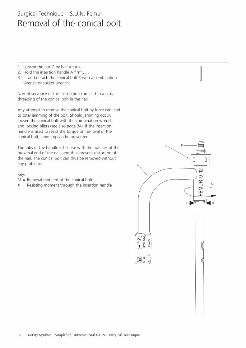
1. Loosen the nut C by half a turn.2. Hold the insertion handle A firmly …3. … and detach the conical bolt B with a combination
wrench or socket wrench.
Non-observance of this instruction can lead to a cross-threading of the conical bolt in the nail.
Any attempt to remove the conical bolt by force can lead to total jamming of the bolt. Should jamming occur, loosen the conical bolt with the combination wrench and locking pliers (see also page 34). If the insertion handle is used to resist the torque on removal of the conical bolt, jamming can be prevented.
The tabs of the handle articulate with the notches of the proximal end of the nail, and thus prevent distortion of the nail. The conical bolt can thus be removed without any problems.
Key:M = Removal moment of the conical boltX = Resisting moment through the insertion handle
Simplified Universal Nail S.U.N. Surgical Technique DePuy Synthes 31
Distal locking of the femur is carried out as distal locking of the S.U.N. Tibia.
Please refer to pages 14 to 19.
Surgical Technique – S.U.N. Femur
Distal Locking
DYNAM.
FEMUR 9–12
STAT.
DYNAM.
FEMUR 9–12
STAT.
DYNAM.
FEMUR 9–12
STAT.
DYNAM.
FEMUR 9–12
STAT.
DYNAM.
FEMUR 9–12
STAT.
32 DePuy Synthes Simplified Universal Nail S.U.N. Surgical Technique
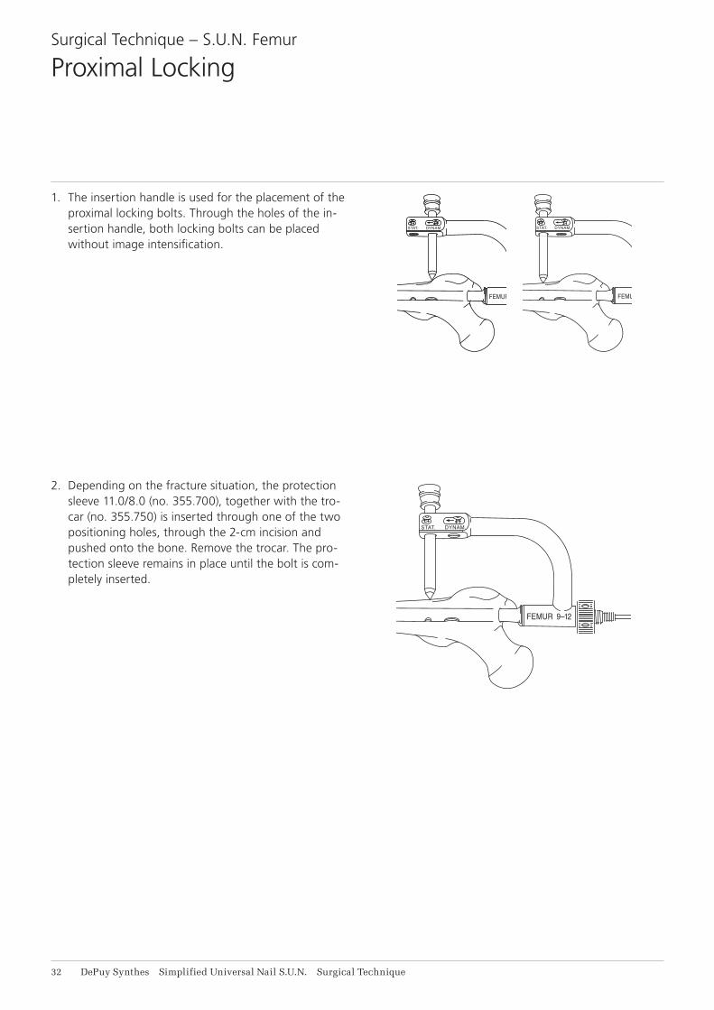
1. The insertion handle is used for the placement of the proximal locking bolts. Through the holes of the in-sertion handle, both locking bolts can be placed without image intensification.
Surgical Technique – S.U.N. Femur
Proximal Locking
2. Depending on the fracture situation, the protection sleeve 11.0/8.0 (no. 355.700), together with the tro-car (no. 355.750) is inserted through one of the two positioning holes, through the 2-cm incision and pushed onto the bone. Remove the trocar. The pro-tection sleeve remains in place until the bolt is com-pletely inserted.
DYNAM.
FEMUR 9–12
STAT.
DYNAM.
FEMUR 9–12
STAT.
DYNAM.
FEMUR 9–12
STAT.
Simplified Universal Nail S.U.N. Surgical Technique DePuy Synthes 33
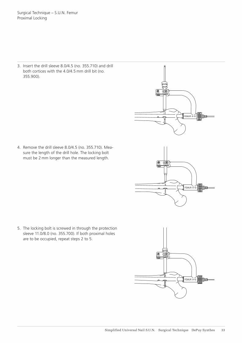
3. Insert the drill sleeve 8.0/4.5 (no. 355.710) and drill both cortices with the 4.0/4.5 mm drill bit (no. 355.900).
4. Remove the drill sleeve 8.0/4.5 (no. 355.710). Mea-sure the length of the drill hole. The locking bolt must be 2 mm longer than the measured length.
5. The locking bolt is screwed in through the protection sleeve 11.0/8.0 (no. 355.700). If both proximal holes are to be occupied, repeat steps 2 to 5.
Surgical Technique – S.U.N. FemurProximal Locking

34 DePuy Synthes Simplified Universal Nail S.U.N. Surgical Technique
The large holding sleeve contained in the instrument set allows a facilitated removal of the locking bolt after healing of the fracture.
1. Large holding sleeve2. Quick release coupling3. Large hexagonal screwdriver
Note: The large holding sleeve (no. 314.280) fits only to the large hexagonal screwdriver (no. 314.270).
1. Push the holding sleeve over the screwdriver shaft as far as it clicks into place.
2. Introduce the screwdriver into the hexagonal recess of the locking bolt.
Removal of the locking bolts
Simplified Universal Nail S.U.N. Surgical Technique DePuy Synthes 31
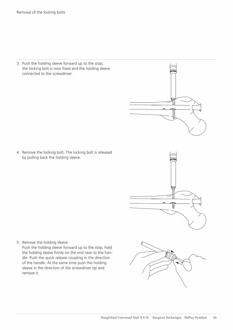
3. Push the holding sleeve forward up to the stop; the locking bolt is now fixed and the holding sleeve connected to the screwdriver.
4. Remove the locking bolt. The locking bolt is released by pulling back the holding sleeve.
5. Remove the holding sleeve: Push the holding sleeve forward up to the stop, hold the holding sleeve firmly on the end near to the han-dle. Push the quick release coupling in the direction of the handle. At the same time push the holding sleeve in the direction of the screwdriver tip and remove it.
Removal of the locking bolts

36 DePuy Synthes Simplified Universal Nail S.U.N. Surgical Technique
Jamming can occur by mistaken use of the short conical bolt contained in the AO/ASIF universal nail instrument set.
As the insertion handle cannot be used over the conical bolts, the removal of these bolts can be very difficult. If this situation should occur, the S.U.N. should be driven out approximately 5 cm. The proximal end of the nail must then be held with a locking wrench. During the loosening of the conical threaded bolt, the locking wrench serves as a torque resistor. This method should only be used in emergency cases.
Loosening of a jammed conical bolt
Simplified Universal Nail S.U.N. Surgical Technique DePuy Synthes 37
The S.U.N. Tibia and Femur are used with the instrument sets of the universal nailing system.
You need:• the Reaming Instrument Set• the Insertion Instrument Set• the Locking Instrument Set
Please refer to the Synthes® catalogue for ordering information.
Instruments

38 DePuy Synthes Simplified Universal Nail S.U.N. Surgical Technique
Implants
4.9 mm Locking Bolts
Item. no. Length
259.260 26 mm
259.280 28 mm
259.300 30 mm
259.320 32 mm
259.340 34 mm
259.360 36 mm
259.380 38 mm
259.400 40 mm
259.420 42 mm
259.440 44 mm
259.460 46 mm
259.480 48 mm
259.500 50 mm
259.520 52 mm
259.540 54 mm
259.560 56 mm
259.580 58 mm
259.600 60 mm
259.640 64 mm
259.680 68 mm
259.720 72 mm
259.760 76 mm
259.800 80 mm
259.850 85 mm
259.900 90 mm
259.950 95 mm
259.960 100 mm
To ensure safe hold in the far cortex, a locking bolt 2 mm longer than measured has to be chosen to allow for the trocar tip.
Thread diameter: 4.9 mmFully threadeddrill bit for threaded hole: 4.0 mmCore diameter: 4.3 mmHexagonal socket: 3.5 mmHead diameter: 8.0 mm
4.9 mm locking bolts, self-tapping, stainless steel

Simplified Universal Nail S.U.N. Surgical Technique DePuy Synthes 39
Item. no. Simplified Universal Nail for Tibia (S.U.N.)
255.927 Simplified Universal Nail for Tibia (S.U.N.), 9 × 270 mm
255.928 Simplified Universal Nail for Tibia (S.U.N.), 9 × 285 mm
255.930 Simplified Universal Nail for Tibia (S.U.N.), 9 × 300 mm
255.931 Simplified Universal Nail for Tibia (S.U.N.), 9 × 315 mm
255.933 Simplified Universal Nail for Tibia (S.U.N.), 9 × 330 mm
255.934 Simplified Universal Nail for Tibia (S.U.N.), 9 × 345 mm
255.936 Simplified Universal Nail for Tibia (S.U.N.), 9 × 360 mm
256.027 Simplified Universal Nail for Tibia (S.U.N.), 10 × 270 mm
256.028 Simplified Universal Nail for Tibia (S.U.N.), 10 × 285 mm
256.030 Simplified Universal Nail for Tibia (S.U.N.), 10 × 300 mm
256.031 Simplified Universal Nail for Tibia (S.U.N.), 10 × 315 mm
256.033 Simplified Universal Nail for Tibia (S.U.N.), 10 × 330 mm
256.034 Simplified Universal Nail for Tibia (S.U.N.), 10 × 345 mm
256.036 Simplified Universal Nail for Tibia (S.U.N.), 10 × 360 mm
256.038 Simplified Universal Nail for Tibia (S.U.N.), 10 × 380 mm
256.127 Simplified Universal Nail for Tibia (S.U.N.), 11 × 270 mm
256.128 Simplified Universal Nail for Tibia (S.U.N.), 11 × 285 mm
256.130 Simplified Universal Nail for Tibia (S.U.N.), 11 × 300 mm
256.131 Simplified Universal Nail for Tibia (S.U.N.), 11 × 315 mm
256.133 Simplified Universal Nail for Tibia (S.U.N.), 11 × 330 mm
256.134 Simplified Universal Nail for Tibia (S.U.N.), 11 × 345 mm
256.136 Simplified Universal Nail for Tibia (S.U.N.), 11 × 360 mm
256.138 Simplified Universal Nail for Tibia (S.U.N.), 11 × 380 mm
256.227 Simplified Universal Nail for Tibia (S.U.N.), 12 × 270 mm
256.228 Simplified Universal Nail for Tibia (S.U.N.), 12 × 285 mm
256.230 Simplified Universal Nail for Tibia (S.U.N.), 12 × 300 mm
256.231 Simplified Universal Nail for Tibia (S.U.N.), 12 × 315 mm
256.233 Simplified Universal Nail for Tibia (S.U.N.), 12 × 330 mm
256.234 Simplified Universal Nail for Tibia (S.U.N.), 12 × 345 mm
256.236 Simplified Universal Nail for Tibia (S.U.N.), 12 × 360 mm
256.238 Simplified Universal Nail for Tibia (S.U.N.), 12 × 380 mm
Simplified Universal Nails S.U.N. for Tibia

41 DePuy Synthes Simplified Universal Nail S.U.N. Surgical Technique
Item. no Simplified Universal Nail for Femur
271.934 Simplified Universal Nail for Femur (S.U.N.), 9 × 340 mm
271.936 Simplified Universal Nail for Femur (S.U.N.), 9 × 360 mm
271.938 Simplified Universal Nail for Femur (S.U.N.), 9 × 380 mm
271.940 Simplified Universal Nail for Femur (S.U.N.), 9 × 400 mm
271.942 Simplified Universal Nail for Femur (S.U.N.), 9 × 420 mm
271.944 Simplified Universal Nail for Femur (S.U.N.), 9 × 440 mm
271.946 Simplified Universal Nail for Femur (S.U.N.), 9 × 460 mm
272.034 Simplified Universal Nail for Femur (S.U.N.), 10 × 340 mm
272.036 Simplified Universal Nail for Femur (S.U.N.), 10 × 360 mm
272.038 Simplified Universal Nail for Femur (S.U.N.), 10 × 380 mm
272.040 Simplified Universal Nail for Femur (S.U.N.), 10 × 400 mm
272.042 Simplified Universal Nail for Femur (S.U.N.), 10 × 420 mm
272.044 Simplified Universal Nail for Femur (S.U.N.), 10 × 440 mm
272.046 Simplified Universal Nail for Femur (S.U.N.), 10 × 460 mm
272.134 Simplified Universal Nail for Femur (S.U.N.), 11 × 340 mm
272.136 Simplified Universal Nail for Femur (S.U.N.), 11 × 360 mm
272.138 Simplified Universal Nail for Femur (S.U.N.), 11 × 380 mm
272.140 Simplified Universal Nail for Femur (S.U.N.), 11 × 400 mm
272.142 Simplified Universal Nail for Femur (S.U.N.), 11 × 420 mm
272.144 Simplified Universal Nail for Femur (S.U.N.), 11 × 440 mm
272.146 Simplified Universal Nail for Femur (S.U.N.), 11 × 460 mm
272.234 Simplified Universal Nail for Femur (S.U.N.), 12 × 340 mm
272.236 Simplified Universal Nail for Femur (S.U.N.), 12 × 360 mm
272.238 Simplified Universal Nail for Femur (S.U.N.), 12 × 380 mm
272.240 Simplified Universal Nail for Femur (S.U.N.), 12 × 400 mm
272.242 Simplified Universal Nail for Femur (S.U.N.), 12 × 420 mm
272.244 Simplified Universal Nail for Femur (S.U.N.), 12 × 440 mm
272.246 Simplified Universal Nail for Femur (S.U.N.), 12 × 460 mm
Simplified Universal Nails S.U.N. for Femur
Simplified Universal Nail S.U.N. Surgical Technique DePuy Synthes 41
Torque, Displacement and Image Artifacts according to ASTM F 2213-06, ASTM F 2052-14 and ASTM F2119-07Non-clinical testing of worst case scenario in a 3 T MRI system did not reveal any relevant torque or displace-ment of the construct for an experimentally measured local spatial gradient of the magnetic field of 3.69 T/m. The largest image artifact extended approximately 169 mm from the construct when scanned using the Gradient Echo (GE). Testing was conducted on a 3 T MRI system.
Radio-Frequency-(RF-)induced heating according to ASTM F2182-11aNon-clinical electromagnetic and thermal testing of worst case scenario lead to peak temperature rise of 9.5 °C with an average temperature rise of 6.6 °C (1.5 T) and a peak temperature rise of 5.9 °C (3 T) under MRI Conditions using RF Coils (whole body averaged specific absorption rate [SAR] of 2 W/kg for 6 minutes [1.5 T] and for 15 minutes [3 T]).
Precautions: The above mentioned test relies on non-clinical testing. The actual temperature rise in the patient will depend on a variety of factors be-yond the SAR and time of RF application. Thus, it is recommended to pay particular attention to the fol-lowing points: • It is recommended to thoroughly monitor patients
undergoing MR scanning for perceived tempera-ture and/or pain sensations.
• Patients with impaired thermoregulation or tem-perature sensation should be excluded from MR scanning procedures.
• Generally, it is recommended to use a MR system with low field strength in the presence of conduc-tive implants. The employed specific absorption rate (SAR) should be reduced as far as possible.
• Using the ventilation system may further contrib-ute to reduce temperature increase in the body.
MRI Information


0123
Synthes GmbHEimattstrasse 34436 OberdorfSwitzerlandTel: +41 61 965 61 11Fax: +41 61 965 66 00www.depuysynthes.com
Not all products are currently available in all markets.
This publication is not intended for distribution in the USA.
All surgical techniques are available as PDF files at www.depuysynthes.com/ifu ©
DeP
uy S
ynth
es T
raum
a, a
div
isio
n of
Syn
thes
Gm
bH. 2
016.
A
ll rig
hts
rese
rved
. 03
6.00
0.51
0 D
ES
M/T
RM
/101
5/05
36(1
) 12
/16