Embed Size (px)
Citation preview
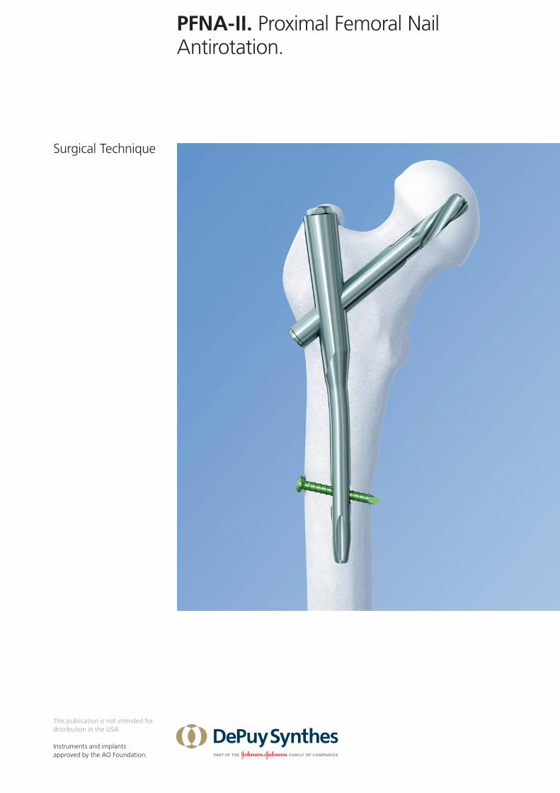
PFNA-II. Proximal Femoral Nail Antirotation.
Surgical Technique
This publication is not intended for distribution in the USA.
Instruments and implants approved by the AO Foundation.

Image intensifier control
This description alone does not provide sufficient background for direct use of DePuy Synthes products. Instruction by a surgeon experienced in handling these products is highly recommended.
Processing, Reprocessing, Care and MaintenanceFor general guidelines, function control and dismantling of multi-part instruments, as well as processing guidelines for implants, please contact your local sales representative or refer to:http://emea.depuysynthes.com/hcp/reprocessing-care-maintenanceFor general information about reprocessing, care and maintenance of Synthes reusable devices, instrument trays and cases, as well as processing of Synthes non-sterile implants, please consult the Important Information leaflet (SE_023827) or refer to: http://emea.depuysynthes.com/hcp/reprocessing-care-maintenance
PFNA-II Surgical Technique DePuy Synthes 1
Table of Contents
Introduction Introduction 2
AO Principles 5
Indications and Contraindications 6
Clinical Cases 7
Surgical Technique Preoperative Planning 8
Patient Positioning 9
Preparation 10
Open Femur 14
Insert Nail 19
Proximal Locking 22
Distal Locking 40 – For PFNA-II Short 42 – For PFNA-II Long 48
Insert End Cap 51
Implant Removal 53
Correction of Insertion Depth of PFNA-II Blade 56
Cleaning 57
Product Information Implants 58
Alternative Implants 64
Instruments 66
Cases 75
MRI Information 79
2 DePuy Synthes PFNA-II Surgical Technique
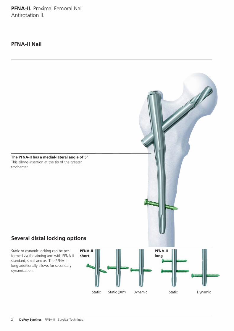
PFNA-II. Proximal Femoral Nail Antirotation II.
PFNA-II Nail
Several distal locking options
Static or dynamic locking can be per-formed via the aiming arm with PFNA-II standard, small and xs. The PFNA-II long additionally allows for secondary dynamization.
The PFNA-II has a medial-lateral angle of 5°This allows insertion at the tip of the greater trochanter.
PFNA-II short
PFNA-II long
Static Dynamic Static DynamicStatic (90°)
PFNA-II Surgical Technique DePuy Synthes 3
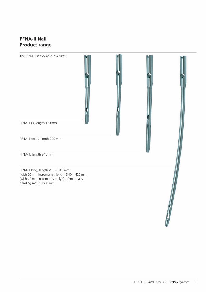
PFNA-II NailProduct range
The PFNA-II is available in 4 sizes
PFNA-II long, length 260 – 340 mm (with 20 mm increments), length 340 – 420 mm (with 40 mm increments, only B 10 mm nails), bending radius 1500 mm
PFNA-II, length 240 mm
PFNA-II small, length 200 mm
PFNA-II xs, length 170 mm
4 DePuy Synthes PFNA-II Surgical Technique
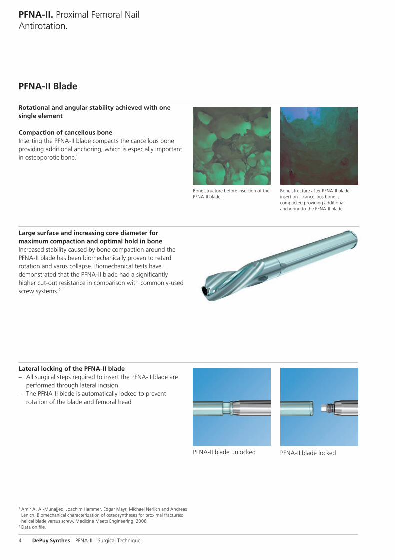
Rotational and angular stability achieved with one single element
Compaction of cancellous boneInserting the PFNA-II blade compacts the cancellous bone providing additional anchoring, which is especially important in osteoporotic bone.1
PFNA-II. Proximal Femoral Nail Antirotation.
PFNA-II Blade
Bone structure after PFNA-II blade inser tion – cancellous bone is compacted providing additional anchoring to the PFNA-II blade.
Large surface and increasing core diameter for maximum compaction and optimal hold in boneIncreased stability caused by bone compaction around the PFNA-II blade has been biomechanically proven to retard rotation and varus collapse. Biomechanical tests have demonstrated that the PFNA-II blade had a significantly higher cut-out resistance in comparison with commonly-used screw systems.2
Lateral locking of the PFNA-II blade – All surgical steps required to insert the PFNA-II blade are
performed through lateral incision – The PFNA-II blade is automatically locked to prevent
rotation of the blade and femoral head
PFNA-II blade unlocked PFNA-II blade locked
Bone structure before insertion of the PFNA-II blade.
1 Amir A. Al-Munajjed, Joachim Hammer, Edgar Mayr, Michael Nerlich and Andreas Lenich. Biomechanical characterization of osteosyntheses for proximal fractures: helical blade versus screw. Medicine Meets Engineering. 2008
2 Data on file.
PFNA-II Surgical Technique DePuy Synthes 5
AO Principles
1 Müller ME, Allgöwer M, Schneider R, Willenegger H. Manual of Internal Fixation. 3rd ed. Berlin, Heidelberg, New York: Springer. 1991.
2 Rüedi TP, Buckley RE, Moran CG. AO Principles of Fracture Management. 2nd ed. Stuttgart, New York: Thieme. 2007.
1
4
2
3
4_Priciples_03.pdf 1 05.07.12 12:08
4 DePuy Synthes Expert Lateral Femoral Nail Surgical Technique
AO PRINCIPLES
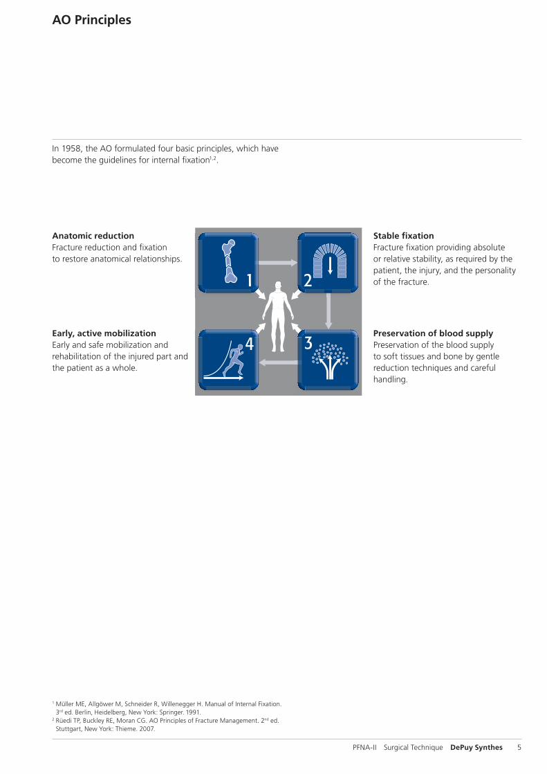
In 1958, the AO formulated four basic principles, which have become the guidelines for internal fixation1, 2.
1 Müller ME, M Allgöwer, R Schneider, H Willenegger. Manual of Internal Fixation. 3rd ed. Berlin Heidelberg New York: Springer. 1991.
2 Rüedi TP, RE Buckley, CG Moran. AO Principles of Fracture Management. 2nd ed. Stuttgart, New York: Thieme. 2007.
Anatomic reductionFracture reduction and fixation to restore anatomical relationships.
Early, active mobilizationEarly and safe mobilization and rehabilitation of the injured part and the patient as a whole.
Stable fixationFracture fixation providing abso-lute or relative stability, as required by the patient, the injury, and the personality of the fracture.
Preservation of blood supplyPreservation of the blood supply to soft tissues and bone by gentle reduction techniques and careful handling.
Stable fixationFracture fixation providing absolute or relative stability, as required by the patient, the injury, and the personality of the fracture.
Anatomic reductionFracture reduction and fixation to restore anatomical relationships.
Early, active mobilizationEarly and safe mobilization and rehabilitation of the injured part and the patient as a whole.
Preservation of blood supplyPreservation of the blood supply to soft tissues and bone by gentle reduction techniques and careful handling.
In 1958, the AO formulated four basic principles, which have become the guidelines for internal fixation1,2.
6 DePuy Synthes PFNA-II Surgical Technique
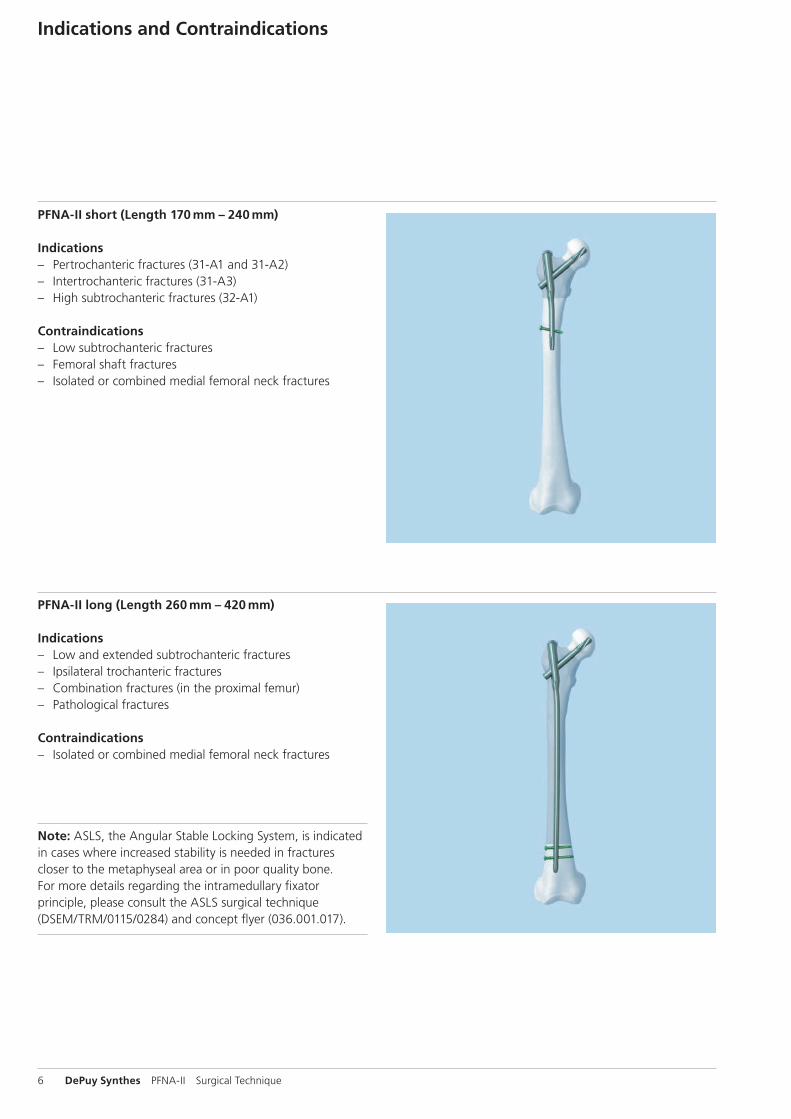
PFNA-II short (Length 170 mm – 240 mm)
Indications – Pertrochanteric fractures (31-A1 and 31-A2) – Intertrochanteric fractures (31-A3) – High subtrochanteric fractures (32-A1)
Contraindications – Low subtrochanteric fractures – Femoral shaft fractures – Isolated or combined medial femoral neck fractures
Indications and Contraindications
PFNA-II long (Length 260 mm – 420 mm)
Indications – Low and extended subtrochanteric fractures – Ipsilateral trochanteric fractures – Combination fractures (in the proximal femur) – Pathological fractures
Contraindications – Isolated or combined medial femoral neck fractures
Note: ASLS, the Angular Stable Locking System, is indicated in cases where increased stability is needed in fractures closer to the metaphyseal area or in poor quality bone. For more details regarding the intramedullary fixator principle, please consult the ASLS surgical technique (DSEM/TRM/0115/0284) and concept flyer (036.001.017).
PFNA-II Surgical Technique DePuy Synthes 7
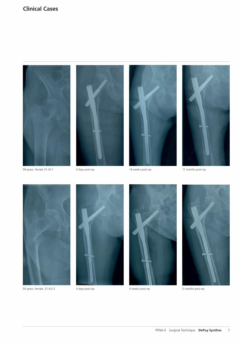
Clinical Cases
94 years, female 31-A1.1 0 days post-op 14 weeks post-op 11 months post-op
93 years, female, 31-A3.3 4 days post-op 4 weeks post-op 5 months post-op
8 DePuy Synthes PFNA-II Surgical Technique
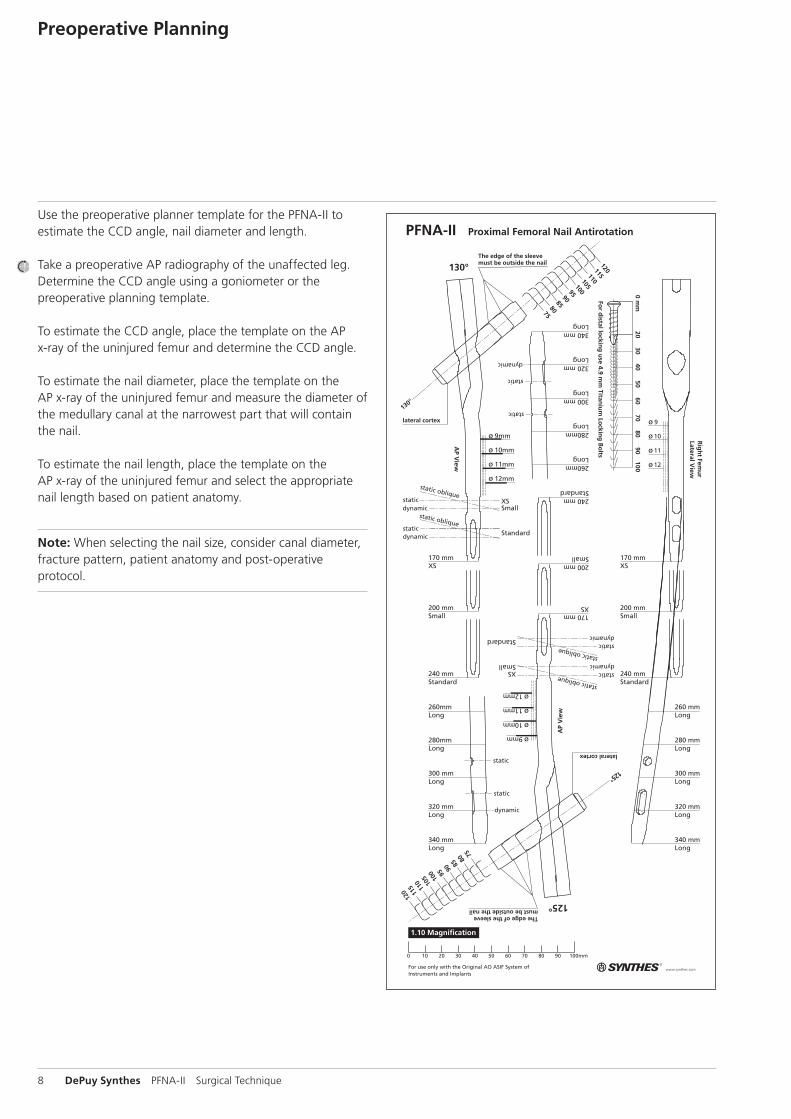
Use the preoperative planner template for the PFNA-II to estimate the CCD angle, nail diameter and length.
Take a preoperative AP radiography of the unaffected leg. Determine the CCD angle using a goniometer or the preoperative planning template.
To estimate the CCD angle, place the template on the AP x-ray of the uninjured femur and determine the CCD angle.
To estimate the nail diameter, place the template on the AP x-ray of the uninjured femur and measure the diameter of the medullary canal at the narrowest part that will contain the nail.
To estimate the nail length, place the template on the AP x-ray of the uninjured femur and select the appropriate nail length based on patient anatomy.
Note: When selecting the nail size, consider canal diameter, fracture pattern, patient anatomy and post-operative protocol.
Preoperative Planning
PFNA-II Surgical Technique DePuy Synthes 9
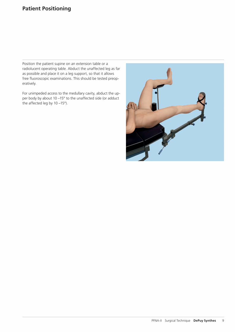
Position the patient supine on an extension table or a radiolucent operating table. Abduct the unaffected leg as far as possible and place it on a leg support, so that it allows free fluoroscopic examinations. This should be tested preop-eratively.
For unimpeded access to the medullary cavity, abduct the up-per body by about 10 –15° to the unaffected side (or adduct the affected leg by 10 –15°).
Patient Positioning
10 DePuy Synthes PFNA-II Surgical Technique
Preparation
1Reduce fracture
Perform closed reduction of the fracture under image intensifier control. If the result is not satisfactory, perform open reduction.
Note: Exact anatomical reduction and secure fixation of the patient to the operating table are essential for easy handling and a good surgical result.
Precautions: – Instruments and screws may have sharp edges or moving
joints that may pinch or tear user’s glove or skin. – Handle devices with care and dispose worn bone cutting
instruments in an approved sharps container.
PFNA-II Surgical Technique DePuy Synthes 11
2Confirm nail length and diameter
Instrument
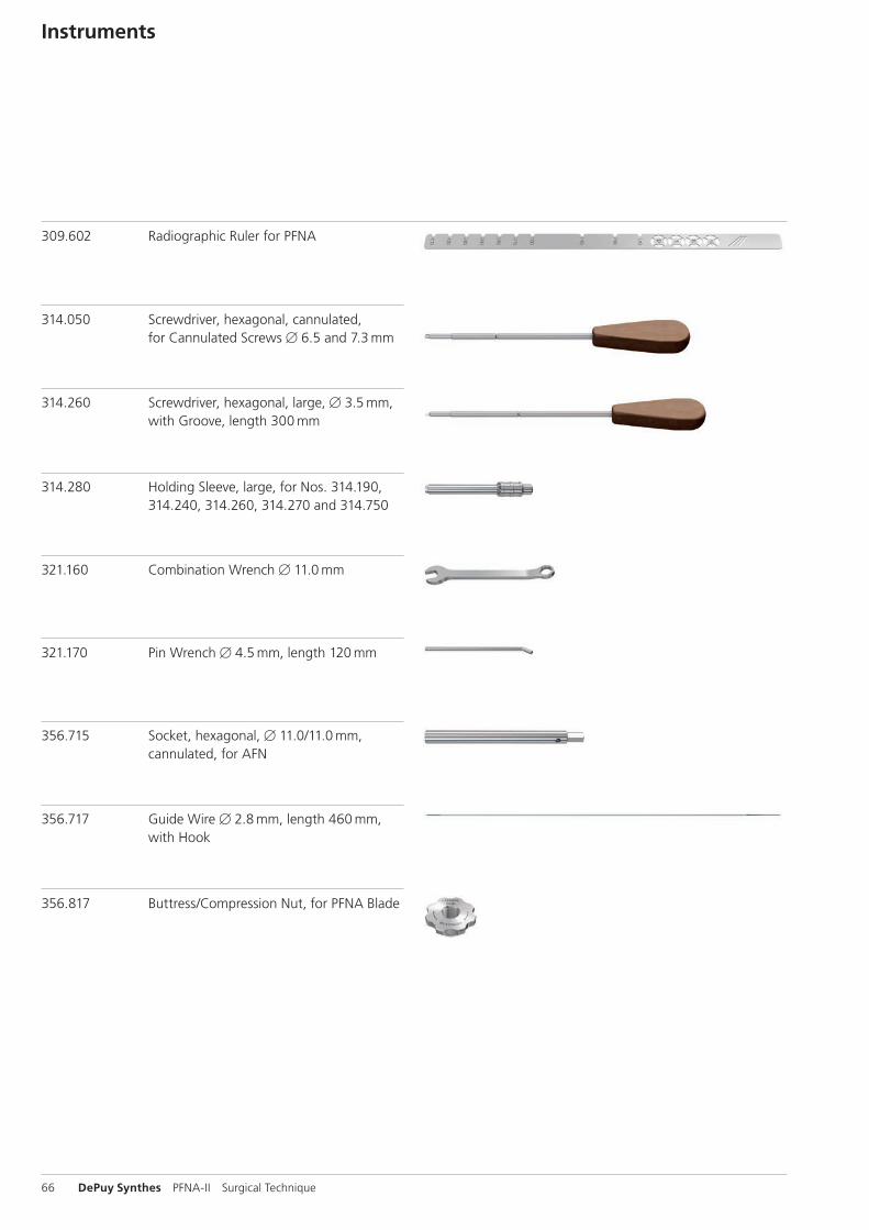
309.602 Radiographic Ruler for PFNA
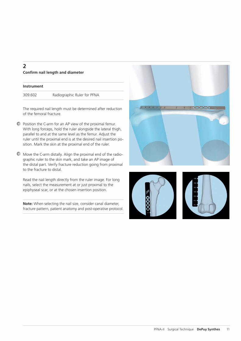
The required nail length must be determined after reduction of the femoral fracture.
Position the C-arm for an AP view of the proximal femur. With long forceps, hold the ruler alongside the lateral thigh, parallel to and at the same level as the femur. Adjust the ruler until the proximal end is at the desired nail insertion po-sition. Mark the skin at the proximal end of the ruler.
Move the C-arm distally. Align the proximal end of the radio-graphic ruler to the skin mark, and take an AP image of the distal part. Verify fracture reduction going from proximal to the fracture to distal.
Read the nail length directly from the ruler image. For long nails, select the measurement at or just proximal to the epiphyseal scar, or at the chosen insertion position.
Note: When selecting the nail size, consider canal diameter, fracture pattern, patient anatomy and post-operative protocol.
12 DePuy Synthes PFNA-II Surgical Technique
Alternatives
Determine the nail length by the procedure above on the uninjured leg before draping (unsterile) or compare the length of two identical SynReam reaming rods B 2.5 mm (352.032) or use the depth gauge (351.717 and 351.719) in combination with the SynReam reaming rod B 2.5 mm, length 950 mm (352.032) before inserting the PFNA-II nail.
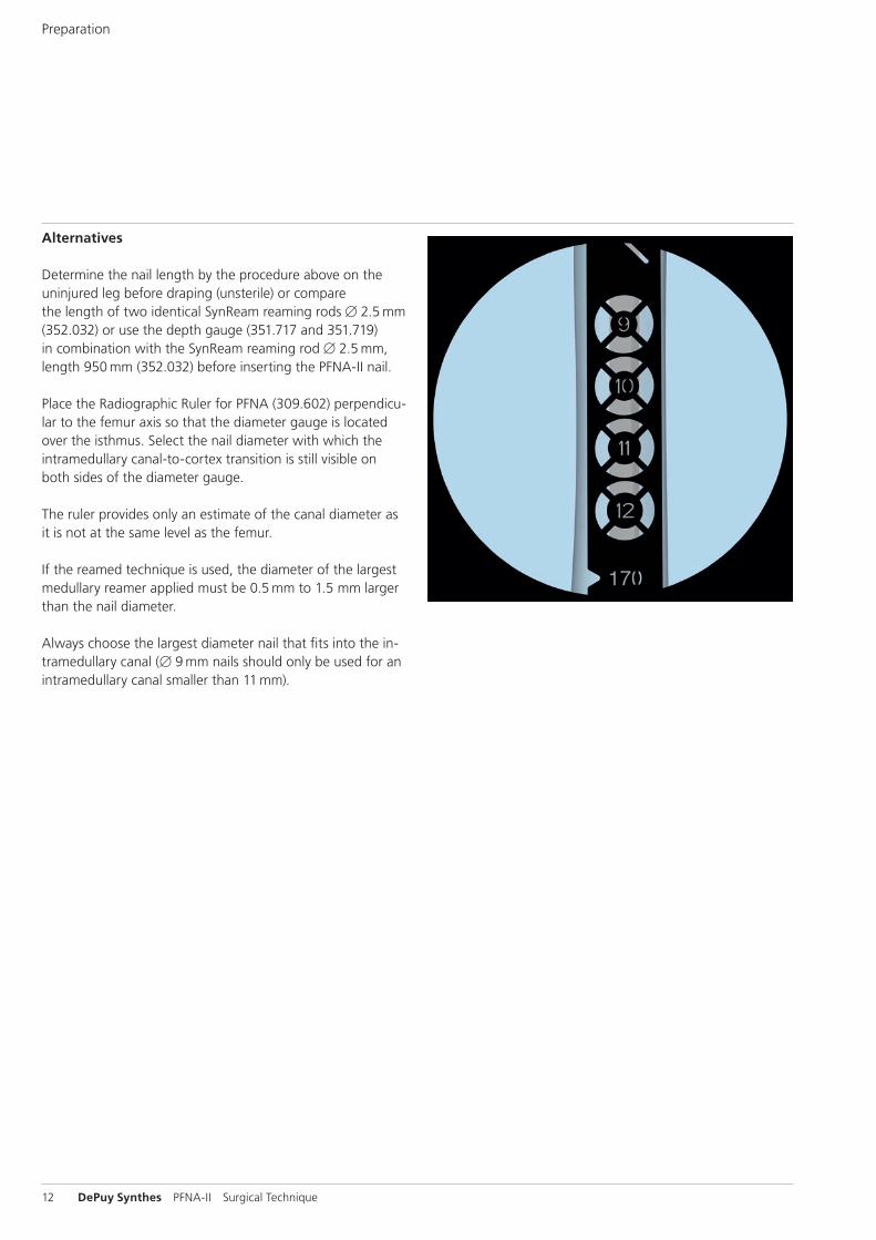
Place the Radiographic Ruler for PFNA (309.602) perpendicu-lar to the femur axis so that the diameter gauge is located over the isthmus. Select the nail diameter with which the intramedullary canal-to-cortex transition is still visible on both sides of the diameter gauge.
The ruler provides only an estimate of the canal diameter as it is not at the same level as the femur.
If the reamed technique is used, the diameter of the largest medullary reamer applied must be 0.5 mm to 1.5 mm larger than the nail diameter.
Always choose the largest diameter nail that fits into the in-tramedullary canal (B 9 mm nails should only be used for an intramedullary canal smaller than 11 mm).
Preparation
PFNA-II Surgical Technique DePuy Synthes 13
3Approach
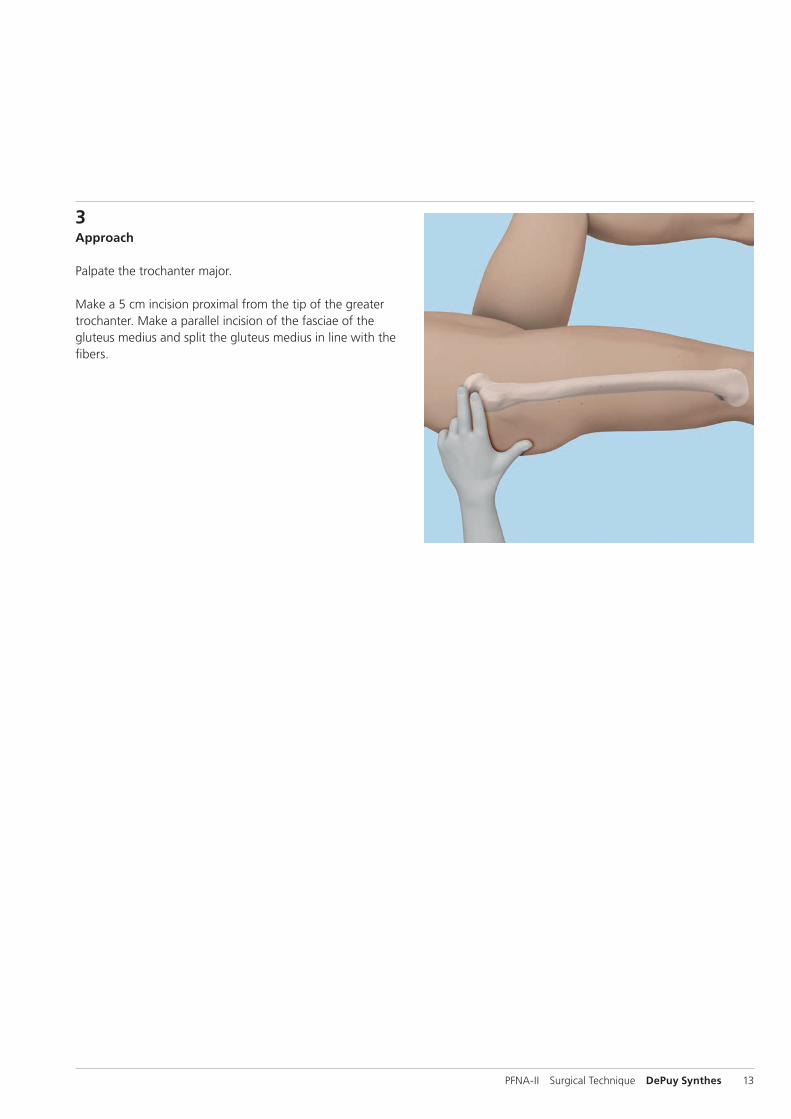
Palpate the trochanter major.
Make a 5 cm incision proximal from the tip of the greater trochanter. Make a parallel incision of the fasciae of the gluteus medius and split the gluteus medius in line with the fibers.
5°
14 DePuy Synthes PFNA-II Surgical Technique
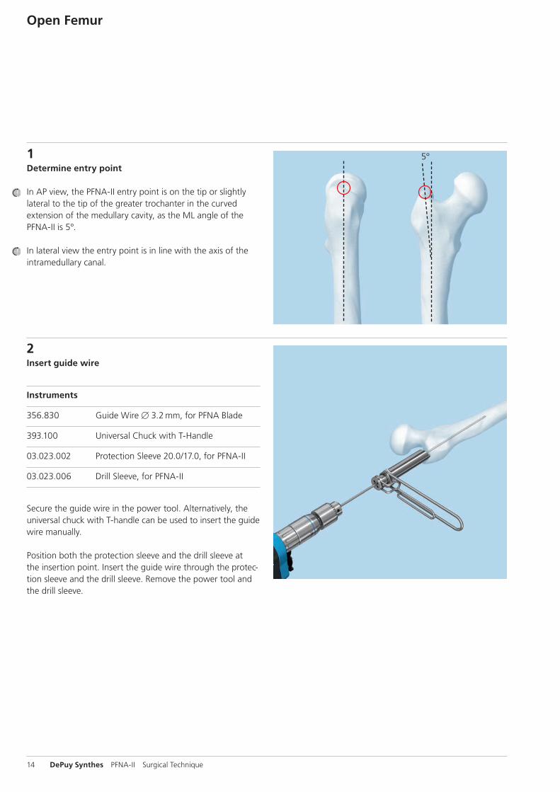
1Determine entry point
In AP view, the PFNA-II entry point is on the tip or slightly lateral to the tip of the greater trochanter in the curved extension of the medullary cavity, as the ML angle of the PFNA-II is 5°.
In lateral view the entry point is in line with the axis of the intramedullary canal.
Open Femur
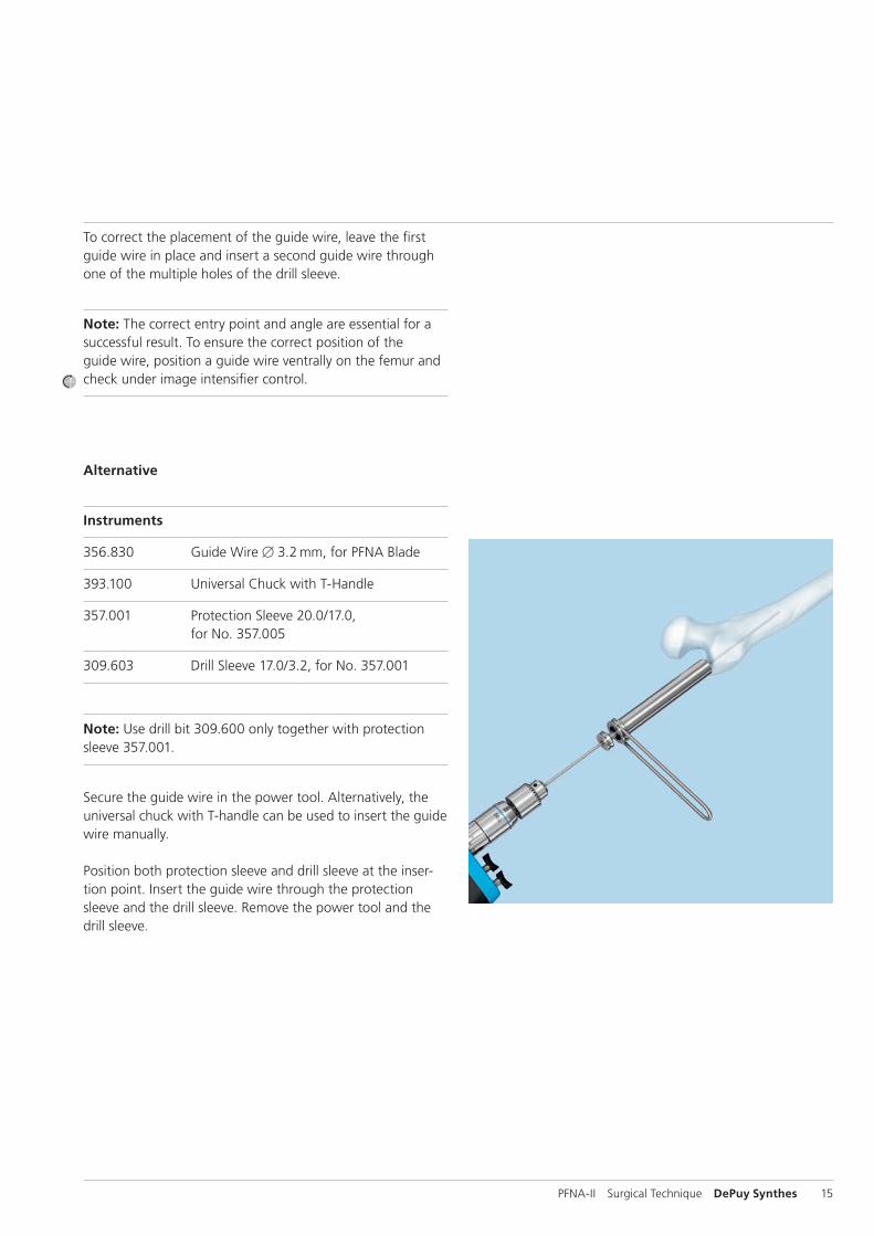
2Insert guide wire
Instruments
356.830 Guide Wire B 3.2 mm, for PFNA Blade
393.100 Universal Chuck with T-Handle
03.023.002 Protection Sleeve 20.0/17.0, for PFNA-II
03.023.006 Drill Sleeve, for PFNA-II
Secure the guide wire in the power tool. Alternatively, the universal chuck with T-handle can be used to insert the guide wire manually.
Position both the protection sleeve and the drill sleeve at the insertion point. Insert the guide wire through the protec-tion sleeve and the drill sleeve. Remove the power tool and the drill sleeve.
PFNA-II Surgical Technique DePuy Synthes 15
To correct the placement of the guide wire, leave the first guide wire in place and insert a second guide wire through one of the multiple holes of the drill sleeve.
Note: The correct entry point and angle are essential for a successful result. To ensure the correct position of the guide wire, position a guide wire ventrally on the femur and check under image intensifier control.
Alternative
Instruments
356.830 Guide Wire B 3.2 mm, for PFNA Blade
393.100 Universal Chuck with T-Handle
357.001 Protection Sleeve 20.0/17.0, for No. 357.005
309.603 Drill Sleeve 17.0/3.2, for No. 357.001
Note: Use drill bit 309.600 only together with protection sleeve 357.001.
Secure the guide wire in the power tool. Alternatively, the universal chuck with T-handle can be used to insert the guide wire manually.
Position both protection sleeve and drill sleeve at the inser-tion point. Insert the guide wire through the protection sleeve and the drill sleeve. Remove the power tool and the drill sleeve.
16 DePuy Synthes PFNA-II Surgical Technique
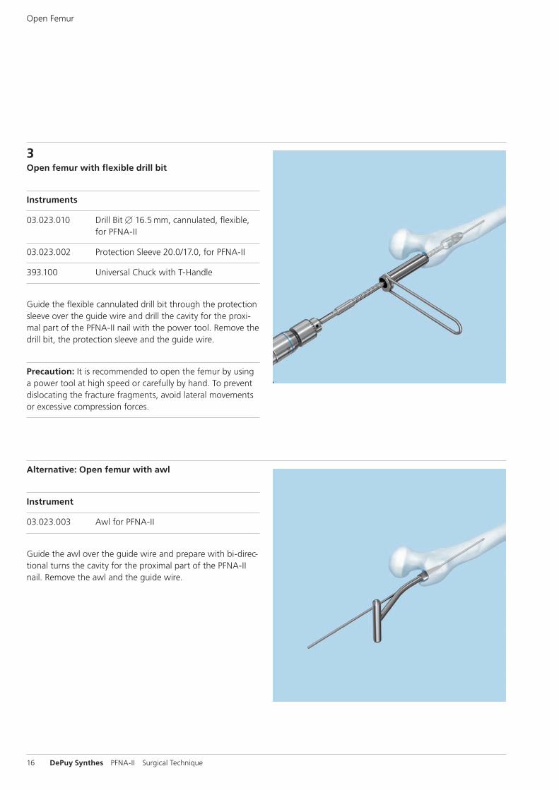
3Open femur with flexible drill bit
Instruments
03.023.010 Drill Bit B 16.5 mm, cannulated, flexible, for PFNA-II
03.023.002 Protection Sleeve 20.0/17.0, for PFNA-II
393.100 Universal Chuck with T-Handle
Guide the flexible cannulated drill bit through the protection sleeve over the guide wire and drill the cavity for the proxi-mal part of the PFNA-II nail with the power tool. Remove the drill bit, the protection sleeve and the guide wire.
Precaution: It is recommended to open the femur by using a power tool at high speed or carefully by hand. To prevent dislocating the fracture fragments, avoid lateral movements or excessive compression forces.
Open Femur
Alternative: Open femur with awl
Instrument
03.023.003 Awl for PFNA-II
Guide the awl over the guide wire and prepare with bi-direc-tional turns the cavity for the proximal part of the PFNA-II nail. Remove the awl and the guide wire.
PFNA-II Surgical Technique DePuy Synthes 17
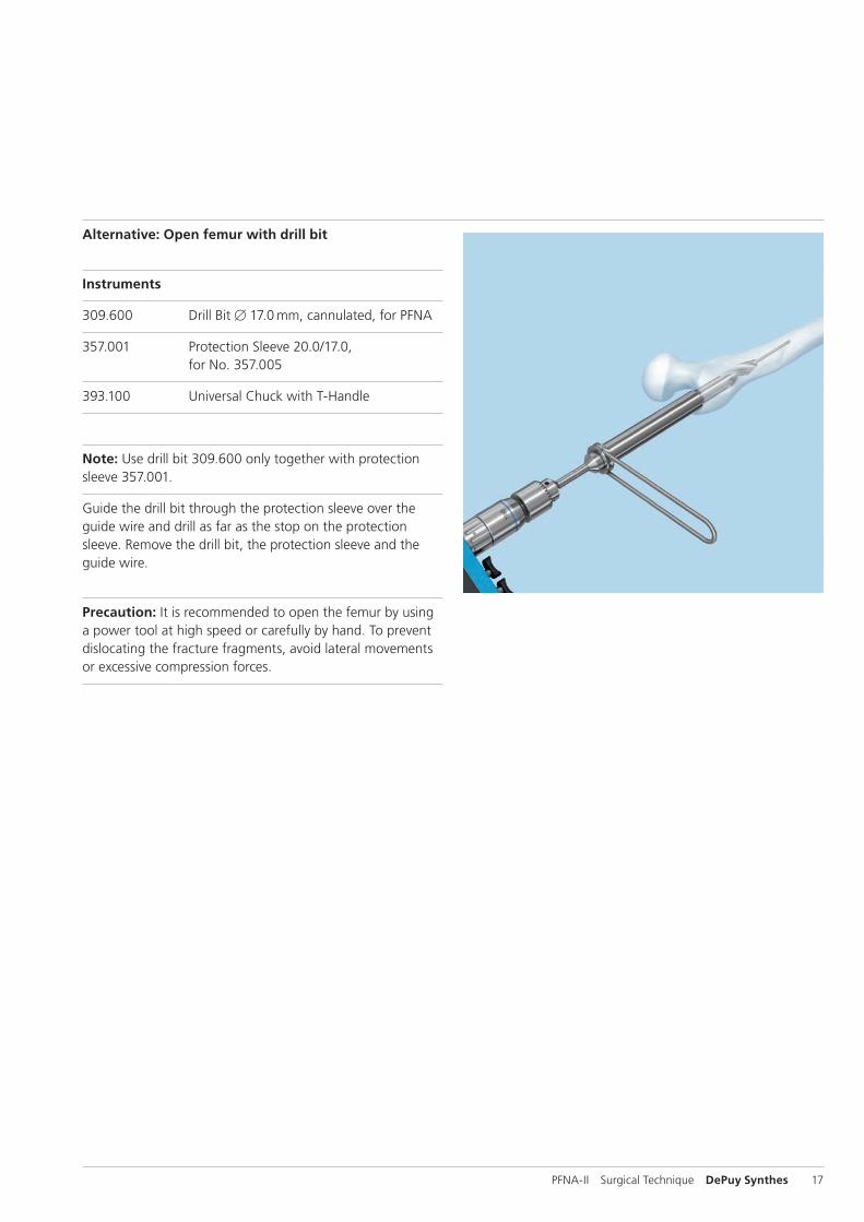
Alternative: Open femur with drill bit
Instruments
309.600 Drill Bit B 17.0 mm, cannulated, for PFNA
357.001 Protection Sleeve 20.0/17.0, for No. 357.005
393.100 Universal Chuck with T-Handle
Note: Use drill bit 309.600 only together with protection sleeve 357.001.
Guide the drill bit through the protection sleeve over the guide wire and drill as far as the stop on the protection sleeve. Remove the drill bit, the protection sleeve and the guide wire.
Precaution: It is recommended to open the femur by using a power tool at high speed or carefully by hand. To prevent dislocating the fracture fragments, avoid lateral movements or excessive compression forces.
18 DePuy Synthes PFNA-II Surgical Technique
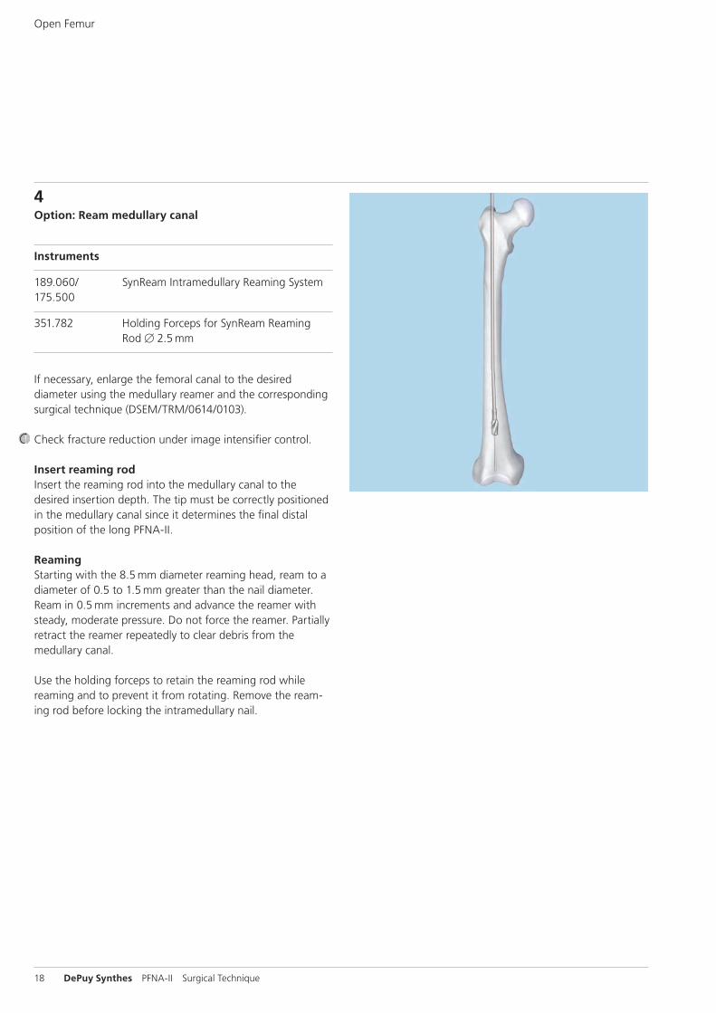
4Option: Ream medullary canal
Instruments
189.060/ SynReam Intramedullary Reaming System 175.500
351.782 Holding Forceps for SynReam Reaming Rod B 2.5 mm
If necessary, enlarge the femoral canal to the desired diameter using the medullary reamer and the corresponding surgical technique (DSEM/TRM/0614/0103).
Check fracture reduction under image intensifier control.
Insert reaming rodInsert the reaming rod into the medullary canal to the desired insertion depth. The tip must be correctly positioned in the medullary canal since it determines the final distal position of the long PFNA-II.
ReamingStarting with the 8.5 mm diameter reaming head, ream to a diameter of 0.5 to 1.5 mm greater than the nail diameter. Ream in 0.5 mm increments and advance the reamer with steady, moderate pressure. Do not force the reamer. Partially retract the reamer repeatedly to clear debris from the medullary canal.
Use the holding forceps to retain the reaming rod while reaming and to prevent it from rotating. Remove the ream-ing rod before locking the intramedullary nail.
Open Femur
PFNA-II Surgical Technique DePuy Synthes 19
Insert Nail
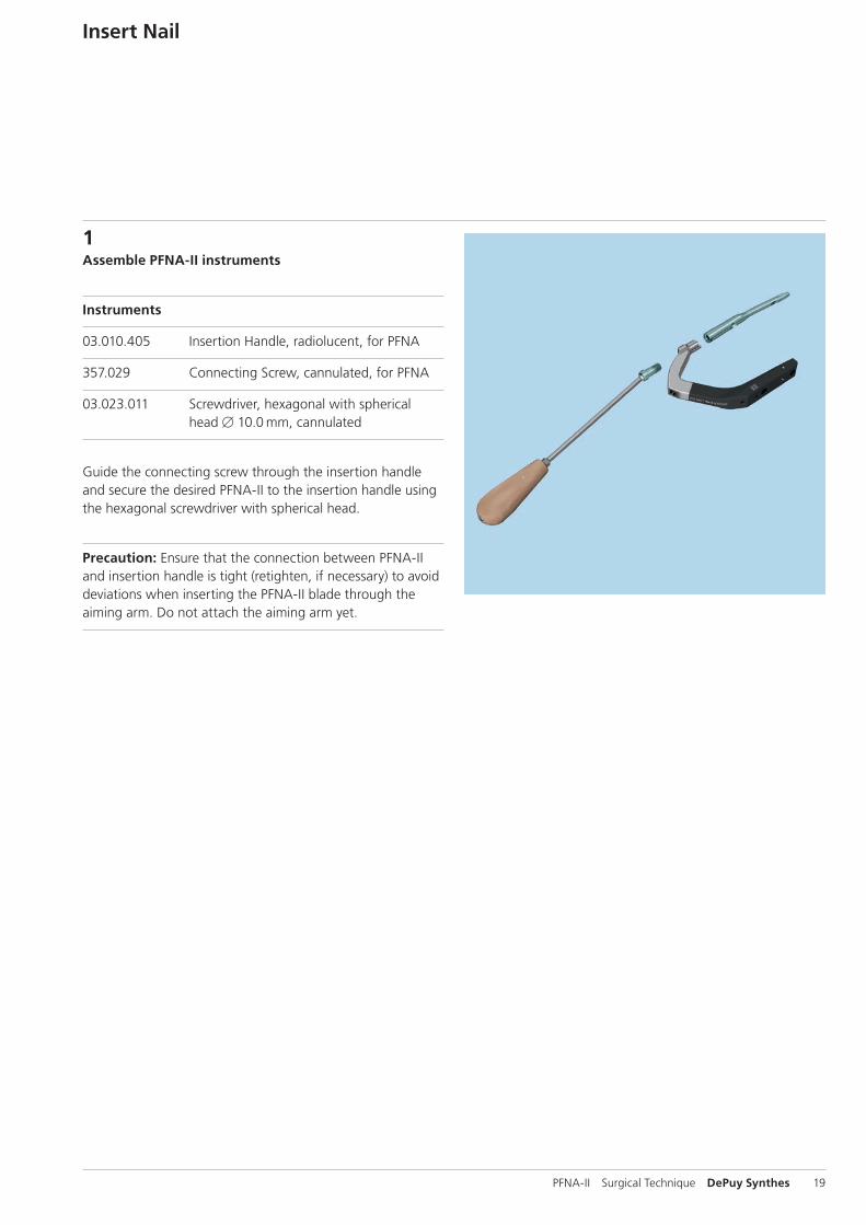
1Assemble PFNA-II instruments
Instruments
03.010.405 Insertion Handle, radiolucent, for PFNA
357.029 Connecting Screw, cannulated, for PFNA
03.023.011 Screwdriver, hexagonal with spherical head B 10.0 mm, cannulated
Guide the connecting screw through the insertion handle and secure the desired PFNA-II to the insertion handle using the hexagonal screwdriver with spherical head.
Precaution: Ensure that the connection between PFNA-II and insertion handle is tight (retighten, if necessary) to avoid deviations when inserting the PFNA-II blade through the aiming arm. Do not attach the aiming arm yet.
20 DePuy Synthes PFNA-II Surgical Technique
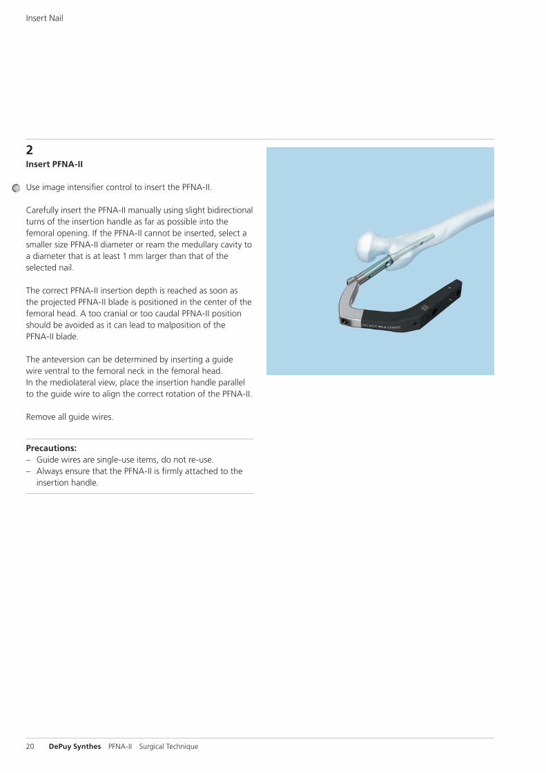
2Insert PFNA-II
Use image intensifier control to insert the PFNA-II.
Carefully insert the PFNA-II manually using slight bidirectional turns of the insertion handle as far as possible into the femoral opening. If the PFNA-II cannot be inserted, select a smaller size PFNA-II diameter or ream the medullary cavity to a diameter that is at least 1 mm larger than that of the selected nail.
The correct PFNA-II insertion depth is reached as soon as the projected PFNA-II blade is positioned in the center of the femoral head. A too cranial or too caudal PFNA-II position should be avoided as it can lead to malposition of thePFNA-II blade.
The anteversion can be determined by inserting a guide wire ventral to the femoral neck in the femoral head. In the mediolateral view, place the insertion handle parallel to the guide wire to align the correct rotation of the PFNA-II.
Remove all guide wires.
Precautions: – Guide wires are single-use items, do not re-use. – Always ensure that the PFNA-II is firmly attached to the
insertion handle.
Insert Nail
PFNA-II Surgical Technique DePuy Synthes 21
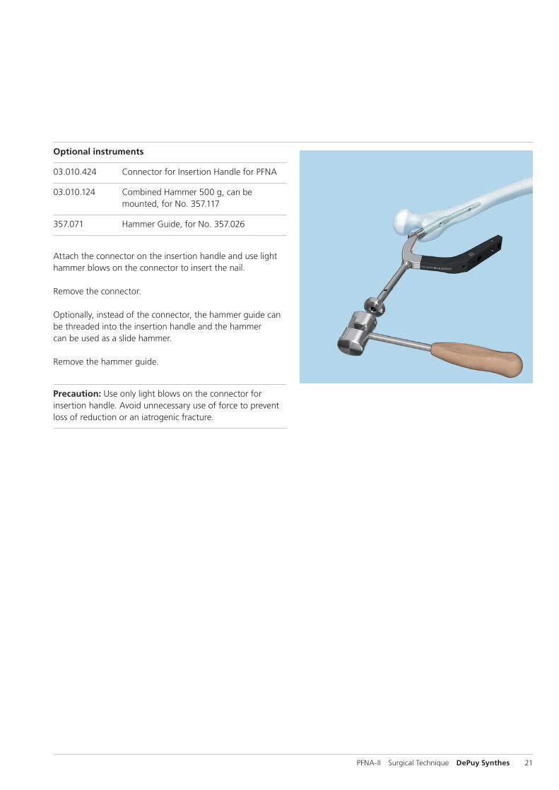
Optional instruments
03.010.424 Connector for Insertion Handle for PFNA
03.010.124 Combined Hammer 500 g, can be mounted, for No. 357.117
357.071 Hammer Guide, for No. 357.026
Attach the connector on the insertion handle and use light hammer blows on the connector to insert the nail.
Remove the connector.
Optionally, instead of the connector, the hammer guide can be threaded into the insertion handle and the hammer can be used as a slide hammer.
Remove the hammer guide.
Precaution: Use only light blows on the con nector for insertion handle. Avoid unnecessary use of force to prevent loss of reduction or an iatrogenic fracture.
22 DePuy Synthes PFNA-II Surgical Technique
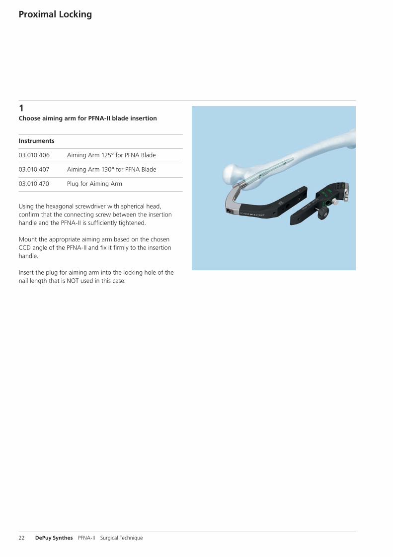
1Choose aiming arm for PFNA-II blade insertion
Instruments
03.010.406 Aiming Arm 125° for PFNA Blade
03.010.407 Aiming Arm 130° for PFNA Blade
03.010.470 Plug for Aiming Arm
Using the hexagonal screwdriver with spherical head, confirm that the connecting screw between the insertion handle and the PFNA-II is sufficiently tightened.
Mount the appropriate aiming arm based on the chosen CCD angle of the PFNA-II and fix it firmly to the insertion handle.
Insert the plug for aiming arm into the locking hole of the nail length that is NOT used in this case.
Proximal Locking
PFNA-II Surgical Technique DePuy Synthes 23
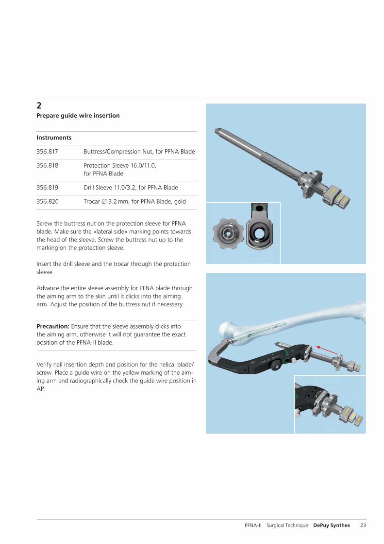
2Prepare guide wire insertion
Instruments
356.817 Buttress/Compression Nut, for PFNA Blade
356.818 Protection Sleeve 16.0/11.0, for PFNA Blade
356.819 Drill Sleeve 11.0/3.2, for PFNA Blade
356.820 Trocar B 3.2 mm, for PFNA Blade, gold
Screw the buttress nut on the protection sleeve for PFNA blade. Make sure the «lateral side» marking points towards the head of the sleeve. Screw the buttress nut up to the marking on the protection sleeve.
Insert the drill sleeve and the trocar through the protection sleeve.
Advance the entire sleeve assembly for PFNA blade through the aiming arm to the skin until it clicks into the aiming arm. Adjust the position of the buttress nut if necessary.
Precaution: Ensure that the sleeve assembly clicks into the aiming arm, otherwise it will not guarantee the exact position of the PFNA-II blade.
Verify nail insertion depth and position for the helical blade/screw. Place a guide wire on the yellow marking of the aim-ing arm and radiographically check the guide wire position in AP.
24 DePuy Synthes PFNA-II Surgical Technique
Proximal Locking
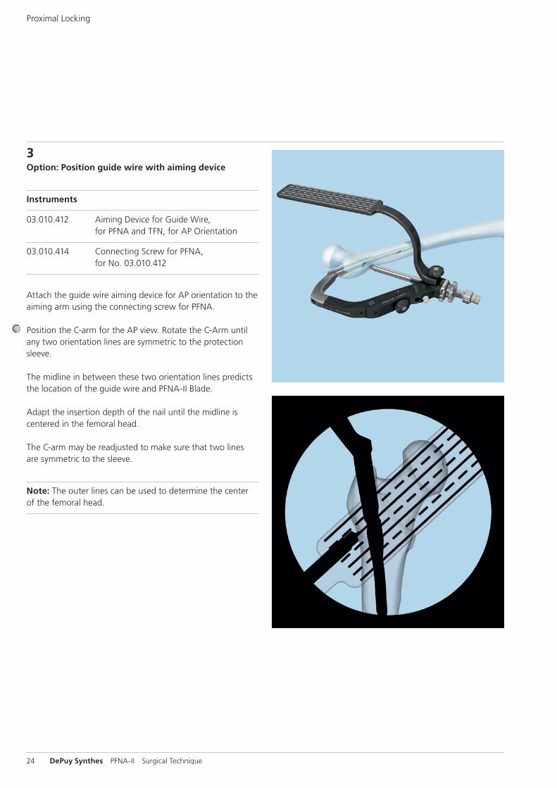
3Option: Position guide wire with aiming device
Instruments
03.010.412 Aiming Device for Guide Wire, for PFNA and TFN, for AP Orientation
03.010.414 Connecting Screw for PFNA, for No. 03.010.412
Attach the guide wire aiming device for AP orientation to the aiming arm using the connecting screw for PFNA.
Position the C-arm for the AP view. Rotate the C-Arm until any two orientation lines are symmetric to the protection sleeve.
The midline in between these two orientation lines predicts the location of the guide wire and PFNA-II Blade.
Adapt the insertion depth of the nail until the midline is centered in the femoral head.
The C-arm may be readjusted to make sure that two lines are symmetric to the sleeve.
Note: The outer lines can be used to determine the center of the femoral head.
PFNA-II Surgical Technique DePuy Synthes 25
1 T. Nishiura, 1077–1083
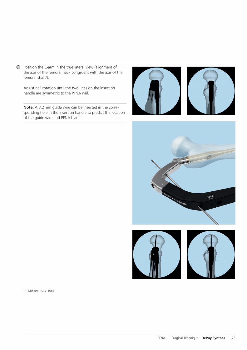
Position the C-arm in the true lateral view (alignment of the axis of the femoral neck congruent with the axis of the femoral shaft1).
Adjust nail rotation until the two lines on the insertion handle are symmetric to the PFNA nail.
Note: A 3.2 mm guide wire can be inserted in the corre-sponding hole in the insertion handle to predict the location of the guide wire and PFNA blade.
26 DePuy Synthes PFNA-II Surgical Technique
Proximal Locking
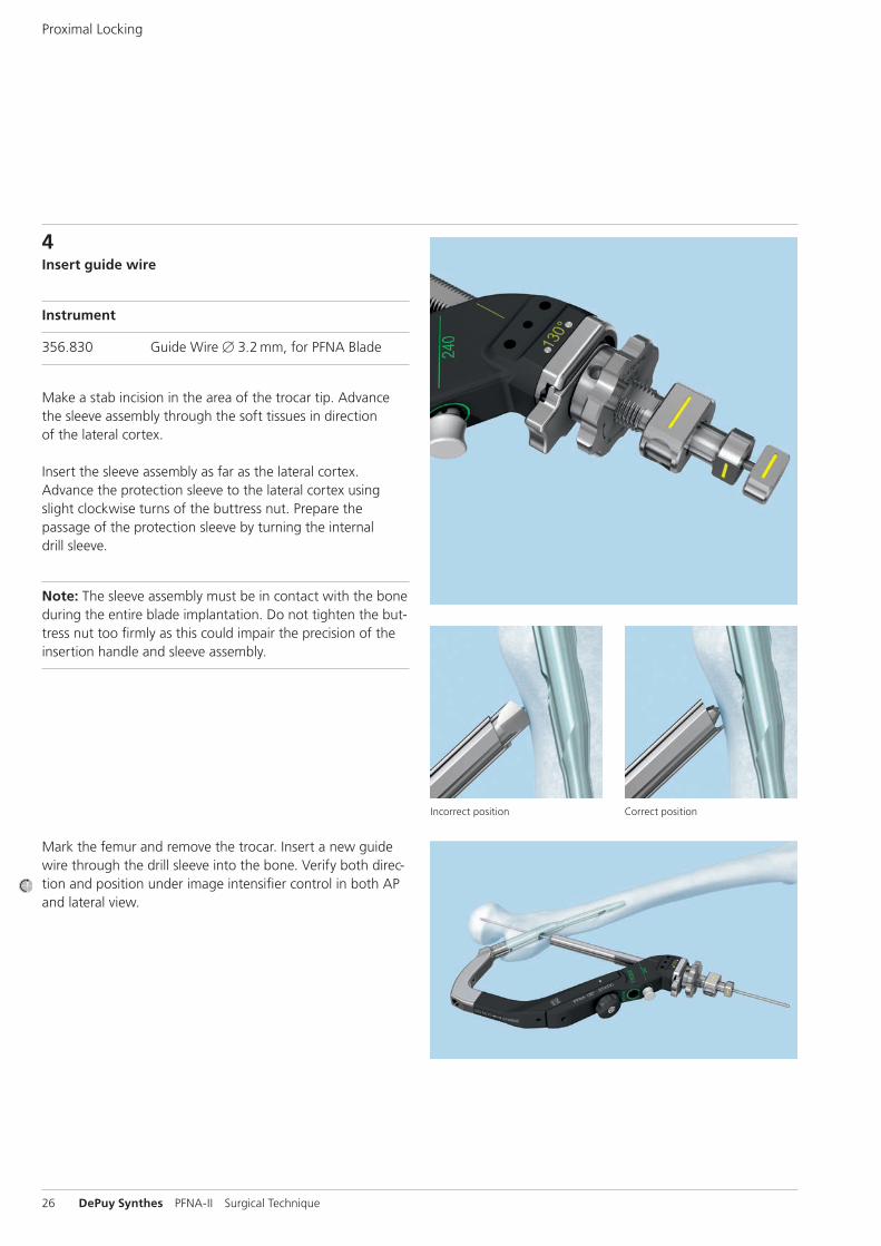
Mark the femur and remove the trocar. Insert a new guide wire through the drill sleeve into the bone. Verify both direc-tion and position under image intensifier control in both AP and lateral view.
Incorrect position Correct position
4Insert guide wire
Instrument
356.830 Guide Wire B 3.2 mm, for PFNA Blade
Make a stab incision in the area of the trocar tip. Advance the sleeve assembly through the soft tissues in direction of the lateral cortex.
Insert the sleeve assembly as far as the lateral cortex. Advance the protection sleeve to the lateral cortex using slight clockwise turns of the buttress nut. Prepare the passage of the protection sleeve by turning the internal drill sleeve.
Note: The sleeve assembly must be in contact with the bone during the entire blade implantation. Do not tighten the but-tress nut too firmly as this could impair the precision of the insertion handle and sleeve assembly.
10 mm
PFNA-II Surgical Technique DePuy Synthes 27
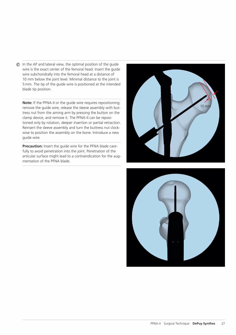
In the AP and lateral view, the optimal position of the guide wire is the exact center of the femoral head. Insert the guide wire subchondrally into the femoral head at a distance of 10 mm below the joint level. Minimal distance to the joint is 5 mm. The tip of the guide wire is positioned at the intended blade tip position.
Note: If the PFNA-II or the guide wire requires repositioning; remove the guide wire, release the sleeve assembly with but-tress nut from the aiming arm by pressing the button on the clamp device, and remove it. The PFNA-II can be reposi-tioned only by rotation, deeper insertion or partial retraction. Reinsert the sleeve assembly and turn the buttress nut clock-wise to position the assembly on the bone. Introduce a new guide wire.
Precaution: Insert the guide wire for the PFNA blade care-fully to avoid penetration into the joint. Penetration of the articular surface might lead to a contraindication for the aug-mentation of the PFNA blade.
28 DePuy Synthes PFNA-II Surgical Technique
Proximal Locking
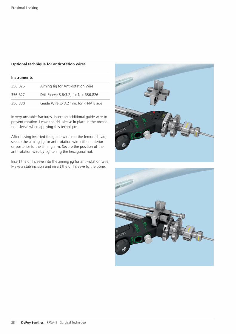
Optional technique for antirotation wires
Instruments
356.826 Aiming Jig for Anti-rotation Wire
356.827 Drill Sleeve 5.6/3.2, for No. 356.826
356.830 Guide Wire B 3.2 mm, for PFNA Blade
In very unstable fractures, insert an additional guide wire to prevent rotation. Leave the drill sleeve in place in the protec-tion sleeve when applying this technique.
After having inserted the guide wire into the femoral head, secure the aiming jig for anti-rotation wire either anterior or posterior to the aiming arm. Secure the position of the anti -rotation wire by tightening the hexagonal nut.
Insert the drill sleeve into the aiming jig for anti-rotation wire. Make a stab incision and insert the drill sleeve to the bone.
PFNA-II Surgical Technique DePuy Synthes 29
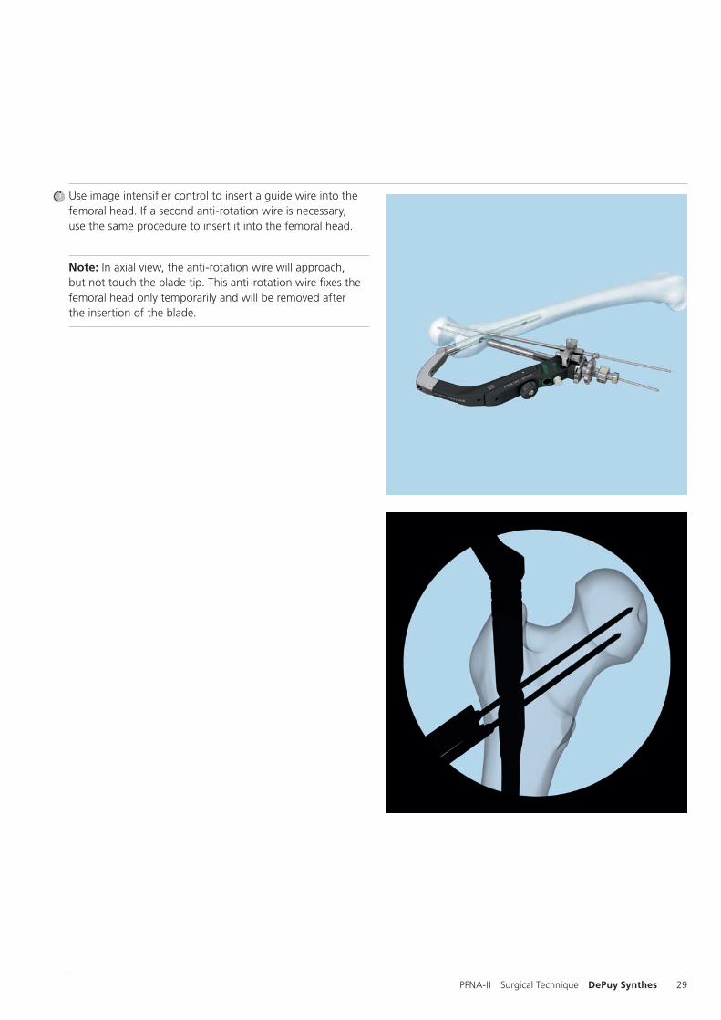
Use image intensifier control to insert a guide wire into the femoral head. If a second anti-rotation wire is necessary, use the same procedure to insert it into the femoral head.
Note: In axial view, the anti-rotation wire will approach, but not touch the blade tip. This anti-rotation wire fixes the femoral head only temporarily and will be removed after the insertion of the blade.
10 mm
30 DePuy Synthes PFNA-II Surgical Technique
Proximal Locking
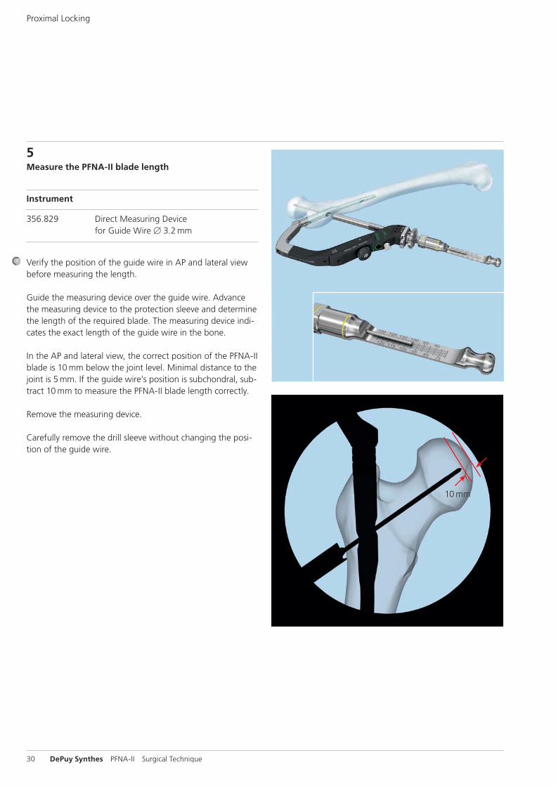
5Measure the PFNA-II blade length
Instrument
356.829 Direct Measuring Device for Guide Wire B 3.2 mm
Verify the position of the guide wire in AP and lateral view before measuring the length.
Guide the measuring device over the guide wire. Advance the measuring device to the protection sleeve and determine the length of the required blade. The measuring device indi-cates the exact length of the guide wire in the bone.
In the AP and lateral view, the correct position of the PFNA-II blade is 10 mm below the joint level. Minimal distance to the joint is 5 mm. If the guide wire’s position is subchondral, sub-tract 10 mm to measure the PFNA-II blade length correctly.
Remove the measuring device.
Carefully remove the drill sleeve without changing the posi-tion of the guide wire.
PFNA-II Surgical Technique DePuy Synthes 31
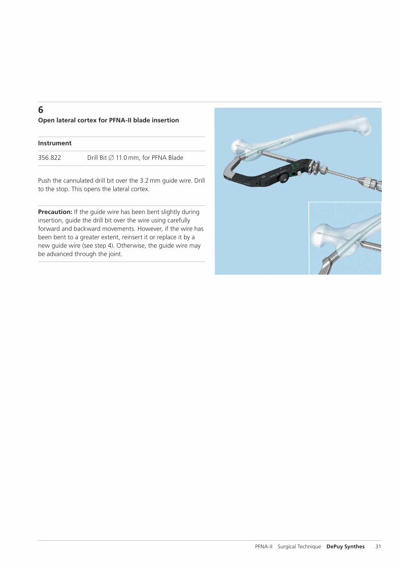
6Open lateral cortex for PFNA-II blade insertion
Instrument
356.822 Drill Bit B 11.0 mm, for PFNA Blade
Push the cannulated drill bit over the 3.2 mm guide wire. Drill to the stop. This opens the lateral cortex.
Precaution: If the guide wire has been bent slightly during insertion, guide the drill bit over the wire using carefully forward and backward movements. However, if the wire has been bent to a greater extent, reinsert it or replace it by a new guide wire (see step 4). Otherwise, the guide wire may be advanced through the joint.
32 DePuy Synthes PFNA-II Surgical Technique
Proximal Locking
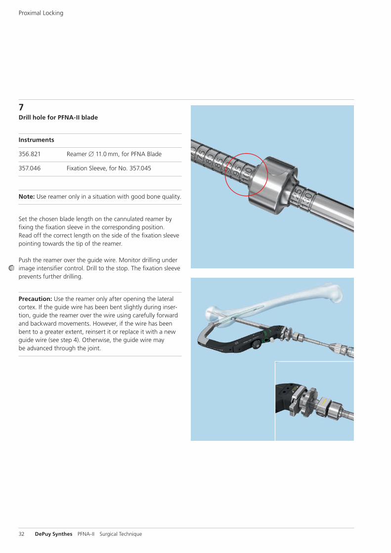
7Drill hole for PFNA-II blade
Instruments
356.821 Reamer B 11.0 mm, for PFNA Blade
357.046 Fixation Sleeve, for No. 357.045
Note: Use reamer only in a situation with good bone quality.
Set the chosen blade length on the cannulated reamer by fixing the fixation sleeve in the corresponding position. Read off the correct length on the side of the fixation sleeve pointing towards the tip of the reamer.
Push the reamer over the guide wire. Monitor drilling under image intensifier control. Drill to the stop. The fixation sleeve prevents further drilling.
Precaution: Use the reamer only after opening the lateral cortex. If the guide wire has been bent slightly during inser-tion, guide the reamer over the wire using carefully forward and backward movements. However, if the wire has been bent to a greater extent, reinsert it or replace it with a new guide wire (see step 4). Otherwise, the guide wire may be advanced through the joint.
PFNA-II Surgical Technique DePuy Synthes 33
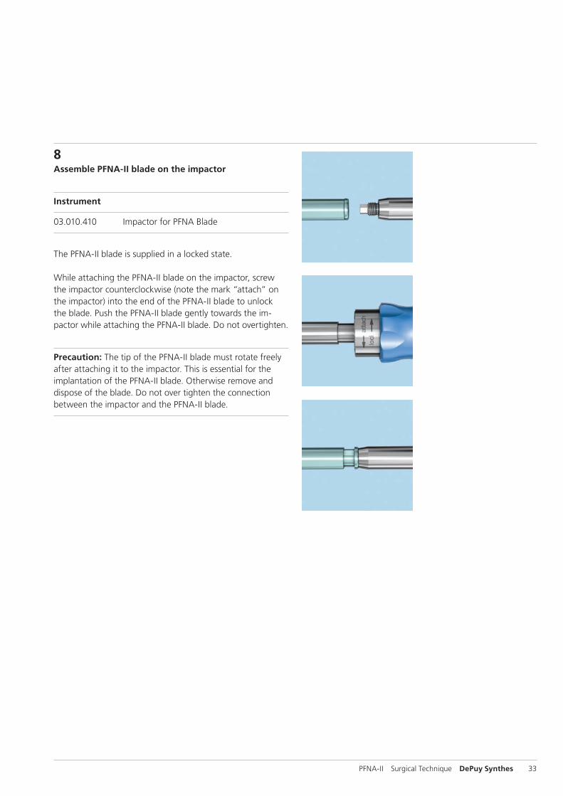
8Assemble PFNA-II blade on the impactor
Instrument
03.010.410 Impactor for PFNA Blade
The PFNA-II blade is supplied in a locked state.
While attaching the PFNA-II blade on the impactor, screw the impactor counterclockwise (note the mark “attach” on the impactor) into the end of the PFNA-II blade to unlock the blade. Push the PFNA-II blade gently towards the im-pactor while attaching the PFNA-II blade. Do not overtighten.
Precaution: The tip of the PFNA-II blade must rotate freely after attaching it to the impactor. This is essential for the implantation of the PFNA-II blade. Otherwise remove and dispose of the blade. Do not over tighten the connection between the impactor and the PFNA-II blade.
34 DePuy Synthes PFNA-II Surgical Technique
Proximal Locking
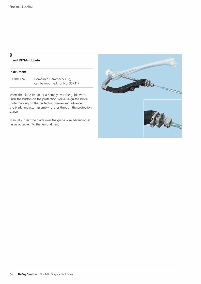
9Insert PFNA-II blade
Instrument
03.010.124 Combined Hammer 500 g, can be mounted, for No. 357.117
Insert the blade-impactor assembly over the guide wire. Push the button on the protection sleeve, align the blade (note marking on the protection sleeve) and advance the blade impactor assembly further through the protection sleeve.
Manually insert the blade over the guide wire advancing as far as possible into the femoral head.
PFNA-II Surgical Technique DePuy Synthes 35
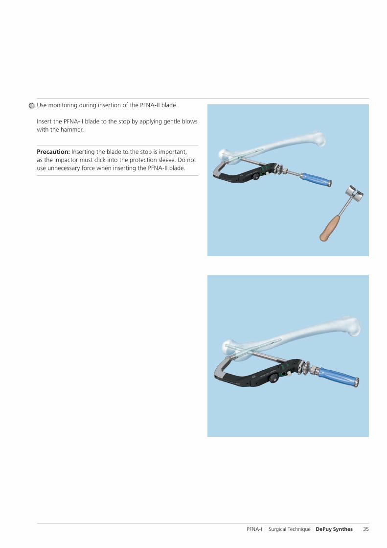
Use monitoring during insertion of the PFNA-II blade.
Insert the PFNA-II blade to the stop by applying gentle blows with the hammer.
Precaution: Inserting the blade to the stop is important, as the impactor must click into the protection sleeve. Do not use unnecessary force when inserting the PFNA-II blade.
36 DePuy Synthes PFNA-II Surgical Technique
Proximal Locking
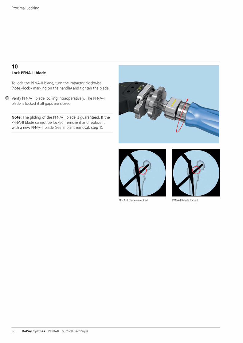
10Lock PFNA-II blade
To lock the PFNA-II blade, turn the impactor clockwise (note «lock» marking on the handle) and tighten the blade.
Verify PFNA-II blade locking intraoperatively. The PFNA-II blade is locked if all gaps are closed.
Note: The gliding of the PFNA-II blade is guaranteed. If the PFNA-II blade cannot be locked, remove it and replace it with a new PFNA-II blade (see implant removal, step 1).
PFNA-II blade unlocked PFNA-II blade locked
PFNA-II Surgical Technique DePuy Synthes 37
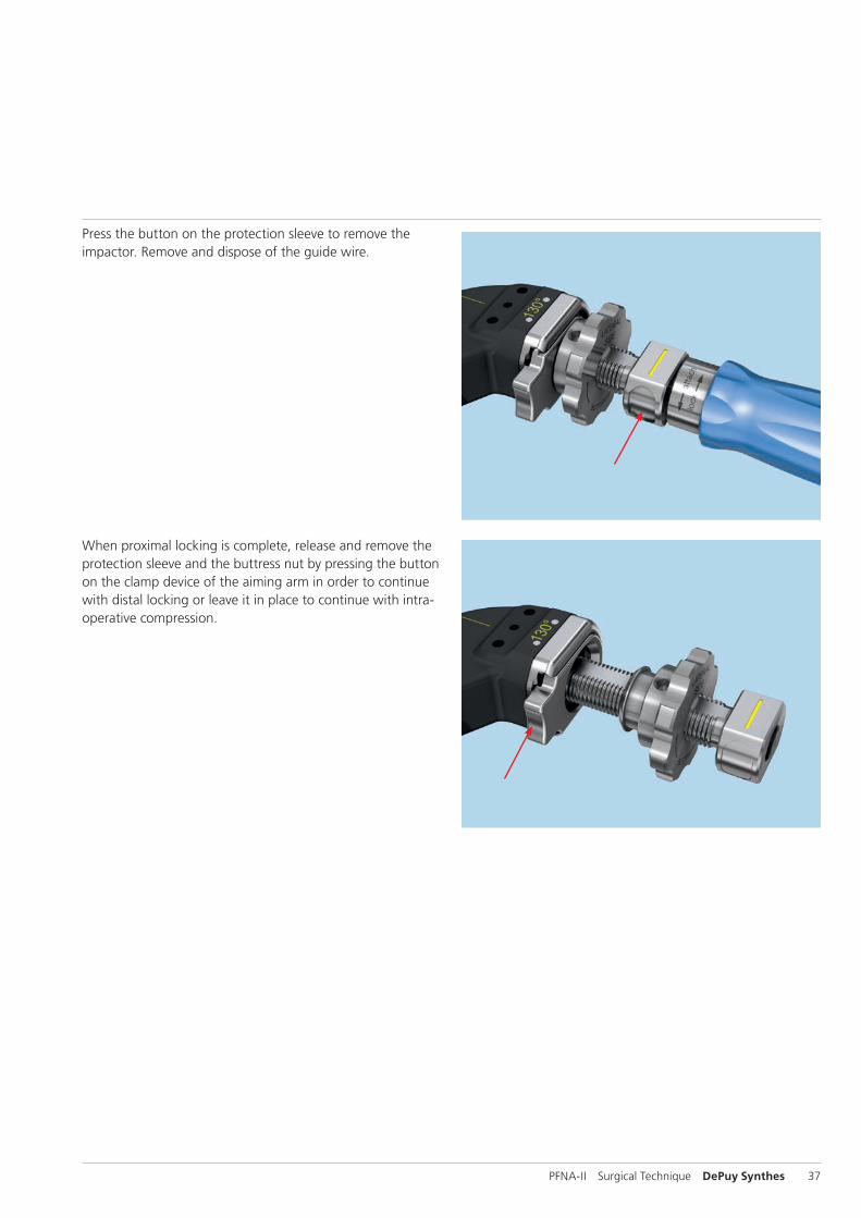
Press the button on the protection sleeve to remove the impactor. Remove and dispose of the guide wire.
When proximal locking is complete, release and remove the protection sleeve and the buttress nut by pressing the button on the clamp device of the aiming arm in order to continue with distal locking or leave it in place to continue with intra-operative compression.
38 DePuy Synthes PFNA-II Surgical Technique
Proximal Locking
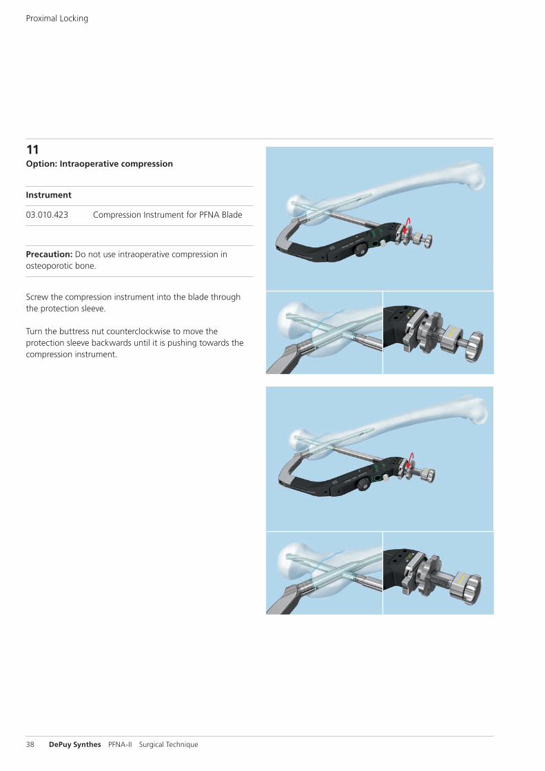
11Option: Intraoperative compression
Instrument
03.010.423 Compression Instrument for PFNA Blade
Precaution: Do not use intraoperative compression in osteoporotic bone.
Screw the compression instrument into the blade through the protection sleeve.
Turn the buttress nut counterclockwise to move the protection sleeve backwards until it is pushing towards the compression instrument.
PFNA-II Surgical Technique DePuy Synthes 39
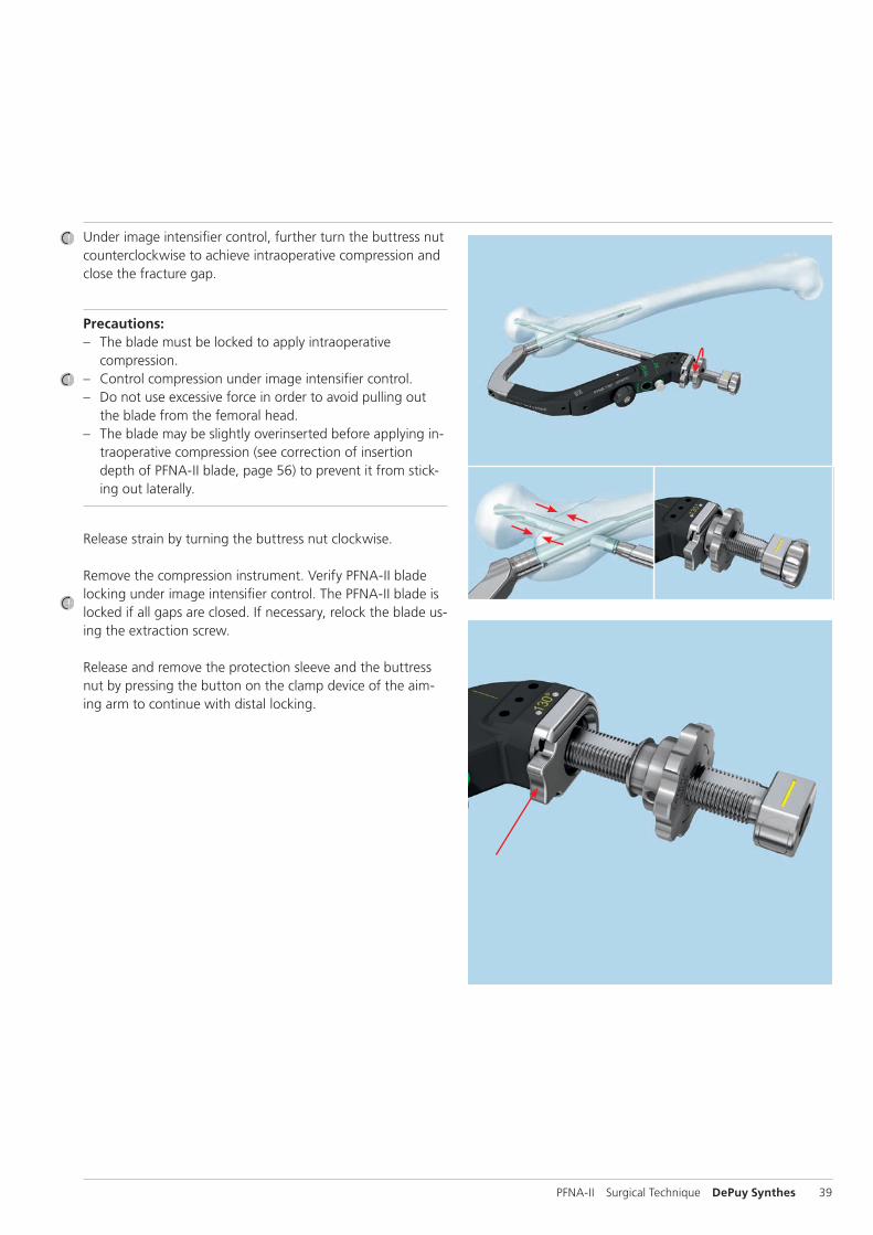
Under image intensifier control, further turn the buttress nut counterclockwise to achieve intraoperative compression and close the fracture gap.
Precautions: – The blade must be locked to apply intraoperative
compression. – Control compression under image intensifier control. – Do not use excessive force in order to avoid pulling out
the blade from the femoral head. – The blade may be slightly overinserted before applying in-
traoperative compression (see correction of insertion depth of PFNA-II blade, page 56) to prevent it from stick-ing out laterally.
Release strain by turning the buttress nut clockwise.
Remove the compression instrument. Verify PFNA-II blade locking under image intensifier control. The PFNA-II blade is locked if all gaps are closed. If necessary, relock the blade us-ing the extraction screw.
Release and remove the protection sleeve and the buttress nut by pressing the button on the clamp device of the aim-ing arm to continue with distal locking.
40 DePuy Synthes PFNA-II Surgical Technique
Distal Locking
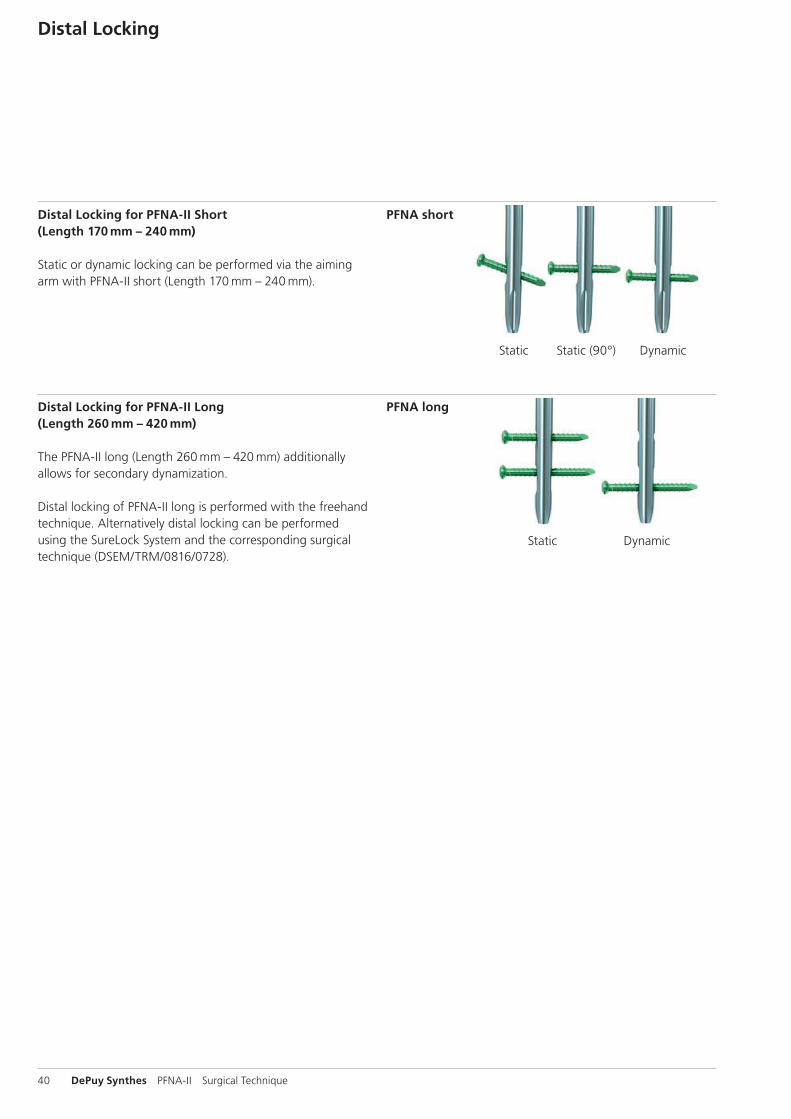
PFNA short
PFNA long
Static Dynamic
Static Dynamic
Distal Locking for PFNA-II Short (Length 170 mm – 240 mm)
Static or dynamic locking can be performed via the aiming arm with PFNA-II short (Length 170 mm – 240 mm).
Distal Locking for PFNA-II Long (Length 260 mm – 420 mm)
The PFNA-II long (Length 260 mm – 420 mm) additionally allows for secondary dynamization.
Distal locking of PFNA-II long is performed with the freehand technique. Alternatively distal locking can be performed using the SureLock System and the corresponding surgical technique (DSEM/TRM/0816/0728).
Static (90°)
PFNA-II Surgical Technique DePuy Synthes 41
Locking implants for distal locking
Distal locking for PFNA-II described in this surgical technique is using the 4.9 mm locking bolts and the corresponding instruments (68.027.002.02: Insert 1, for B 4.9 mm locking bolts, from instrument set 01.027.101).
Alternatively, the 5.0 mm locking screws from the Expert Nailing Systems can be used with the corresponding instru-ments (68.027.002.03: Insert 1, for B 5.0 mm locking screws, from instrument set 01.027.102) for distal locking of the PFNA-II.
See table below for corresponding instruments.
Short PFNA-II Nails (170 mm – 240 mm)
Locking Bolts B 4.9 mm Locking Screws B 5.0 mm
Part No. Description Part No. Description
356.834 Drill Bit B 4.0 mm, for PFNA 03.010.061 Drill Bit B 4.2 mm, calibrated, length 340 mm, 3-flute, for Quick Coupling
356.831 Protection Sleeve 11.0/8.0, green 03.025.040 Protection Sleeve 11.0/8.0, lenght 188 mm
356.828 Drill Sleeve 8.0/4.0, green 03.010.065 Drill Sleeve 8.0/4.2
356.833 Trocar B 4.0 mm, green 03.010.070 Trocar B 4.2 mm
356.835 Measuring Device for Locking Bolt 03.010.428 Depth Gauge for Locking Screws, measuring range to 110 mm
314.260 Screwdriver, hexagonal, large, B 3.5 mm, 03.010.107 Screwdriver Stardrive, SD25, length 330 mm with Groove, length 300 mm
Long PFNA-II Nails (260 mm – 420 mm)
Locking Bolts B 4.9 mm Locking Screws B 5.0 mm
Part No. Description Part No. Description
356.834 Drill Bit B 4.0 mm, for PFNA 03.010.101 Drill Bit B 4.2 mm, calibrated, length 145 mm, 3-flute, with Coupling for RDL
03.010.104 Drill Bit B 4.2 mm, calibrated, length 145 mm, 3-flute, for Quick Coupling
356.835 Measuring Device for Locking Bolt 03.010.019 Depth Gauge for Locking Screws, measuring range up to 110 mm for No. 03.010.009
03.010.429 Direct Measuring Device for Drill Bits, length 145 mm
314.260 Screwdriver, hexagonal, large, B 3.5 mm, 03.010.362 Screwdriver Stardrive, SD25, length 275 mm with Groove, length 300 mm
314.280 Holding Sleeve, large 03.010.112 Holding Sleeve, with Locking Device
42 DePuy Synthes PFNA-II Surgical Technique
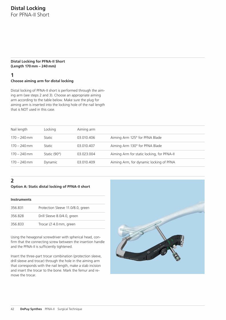
Distal Locking for PFNA-II Short (Length 170 mm – 240 mm)
1Choose aiming arm for distal locking
Distal locking of PFNA-II short is performed through the aim-ing arm (see steps 2 and 3). Choose an appropriate aiming arm according to the table below. Make sure the plug for aiming arm is inserted into the locking hole of the nail length that is NOT used in this case.
Nail length Locking Aiming arm
170 – 240 mm Static 03.010.406 Aiming Arm 125° for PFNA Blade
170 – 240 mm Static 03.010.407 Aiming Arm 130° for PFNA Blade
170 – 240 mm Static (90°) 03.023.004 Aiming Arm for static locking, for PFNA-II
170 – 240 mm Dynamic 03.010.409 Aiming Arm, for dynamic locking of PFNA
2Option A: Static distal locking of PFNA-II short
Instruments
356.831 Protection Sleeve 11.0/8.0, green
356.828 Drill Sleeve 8.0/4.0, green
356.833 Trocar B 4.0 mm, green
Using the hexagonal screwdriver with spherical head, con-firm that the connecting screw between the insertion handle and the PFNA-II is sufficiently tightened.
Insert the three-part trocar combination (protection sleeve, drill sleeve and trocar) through the hole in the aiming arm that corresponds with the nail length, make a stab incision and insert the trocar to the bone. Mark the femur and re-move the trocar.
Distal LockingFor PFNA-II Short
PFNA-II Surgical Technique DePuy Synthes 43
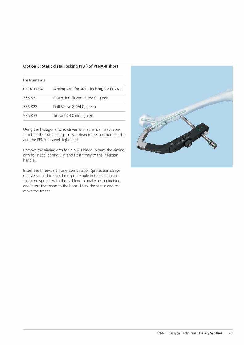
Option B: Static distal locking (90°) of PFNA-II short
Instruments
03.023.004 Aiming Arm for static locking, for PFNA-II
356.831 Protection Sleeve 11.0/8.0, green
356.828 Drill Sleeve 8.0/4.0, green
536.833 Trocar B 4.0 mm, green
Using the hexagonal screwdriver with spherical head, con-firm that the connecting screw between the insertion handle and the PFNA-II is well tightened.
Remove the aiming arm for PFNA-II blade. Mount the aiming arm for static locking 90° and fix it firmly to the insertion handle.
Insert the three-part trocar combination (protection sleeve, drill sleeve and trocar) through the hole in the aiming arm that corresponds with the nail length, make a stab incision and insert the trocar to the bone. Mark the femur and re-move the trocar.
44 DePuy Synthes PFNA-II Surgical Technique
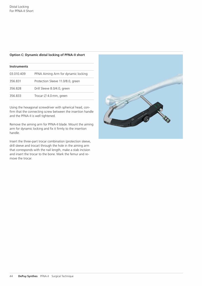
Option C: Dynamic distal locking of PFNA-II short
Instruments
03.010.409 PFNA Aiming Arm for dynamic locking
356.831 Protection Sleeve 11.0/8.0, green
356.828 Drill Sleeve 8.0/4.0, green
356.833 Trocar B 4.0 mm, green
Using the hexagonal screwdriver with spherical head, con-firm that the connecting screw between the insertion handle and the PFNA-II is well tightened.
Remove the aiming arm for PFNA-II blade. Mount the aiming arm for dynamic locking and fix it firmly to the insertion handle.
Insert the three-part trocar combination (protection sleeve, drill sleeve and trocar) through the hole in the aiming arm that corresponds with the nail length, make a stab incision and insert the trocar to the bone. Mark the femur and re-move the trocar.
Distal Locking For PFNA-II Short
PFNA-II Surgical Technique DePuy Synthes 45
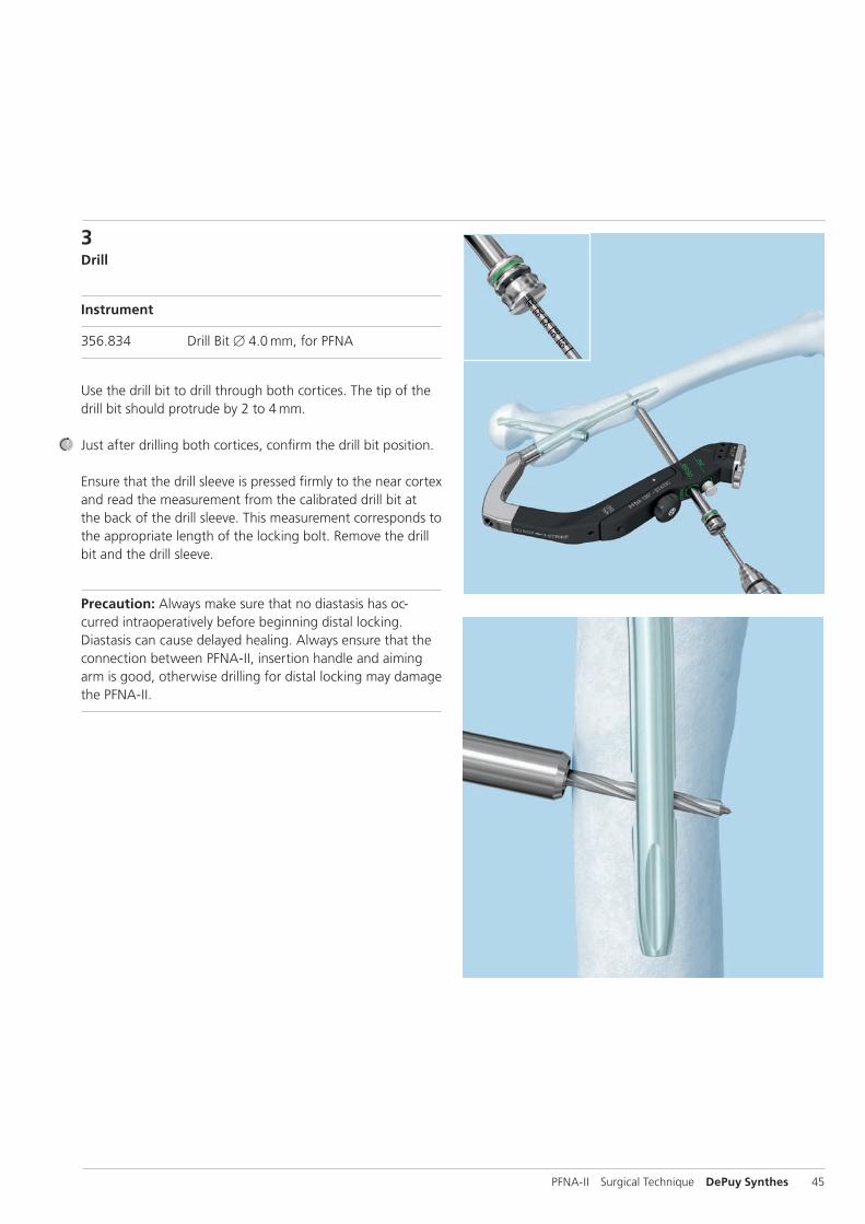
3Drill
Instrument
356.834 Drill Bit B 4.0 mm, for PFNA
Use the drill bit to drill through both cortices. The tip of the drill bit should protrude by 2 to 4 mm.
Just after drilling both cortices, confirm the drill bit position.
Ensure that the drill sleeve is pressed firmly to the near cortex and read the measurement from the calibrated drill bit at the back of the drill sleeve. This measurement corresponds to the appropriate length of the locking bolt. Remove the drill bit and the drill sleeve.
Precaution: Always make sure that no diastasis has oc-curred intraoperatively before beginning distal locking. Diastasis can cause delayed healing. Always ensure that the connection between PFNA-II, insertion handle and aiming arm is good, otherwise drilling for distal locking may damage the PFNA-II.
46 DePuy Synthes PFNA-II Surgical Technique
Distal Locking For PFNA-II Short
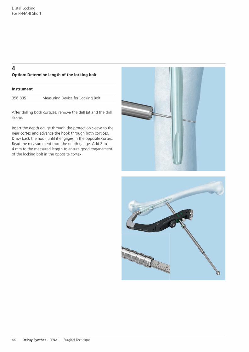
4Option: Determine length of the locking bolt
Instrument
356.835 Measuring Device for Locking Bolt
After drilling both cortices, remove the drill bit and the drill sleeve.
Insert the depth gauge through the protection sleeve to the near cortex and advance the hook through both cortices. Draw back the hook until it engages in the opposite cortex. Read the measurement from the depth gauge. Add 2 to 4 mm to the measured length to ensure good engagement of the locking bolt in the opposite cortex.
PFNA-II Surgical Technique DePuy Synthes 47
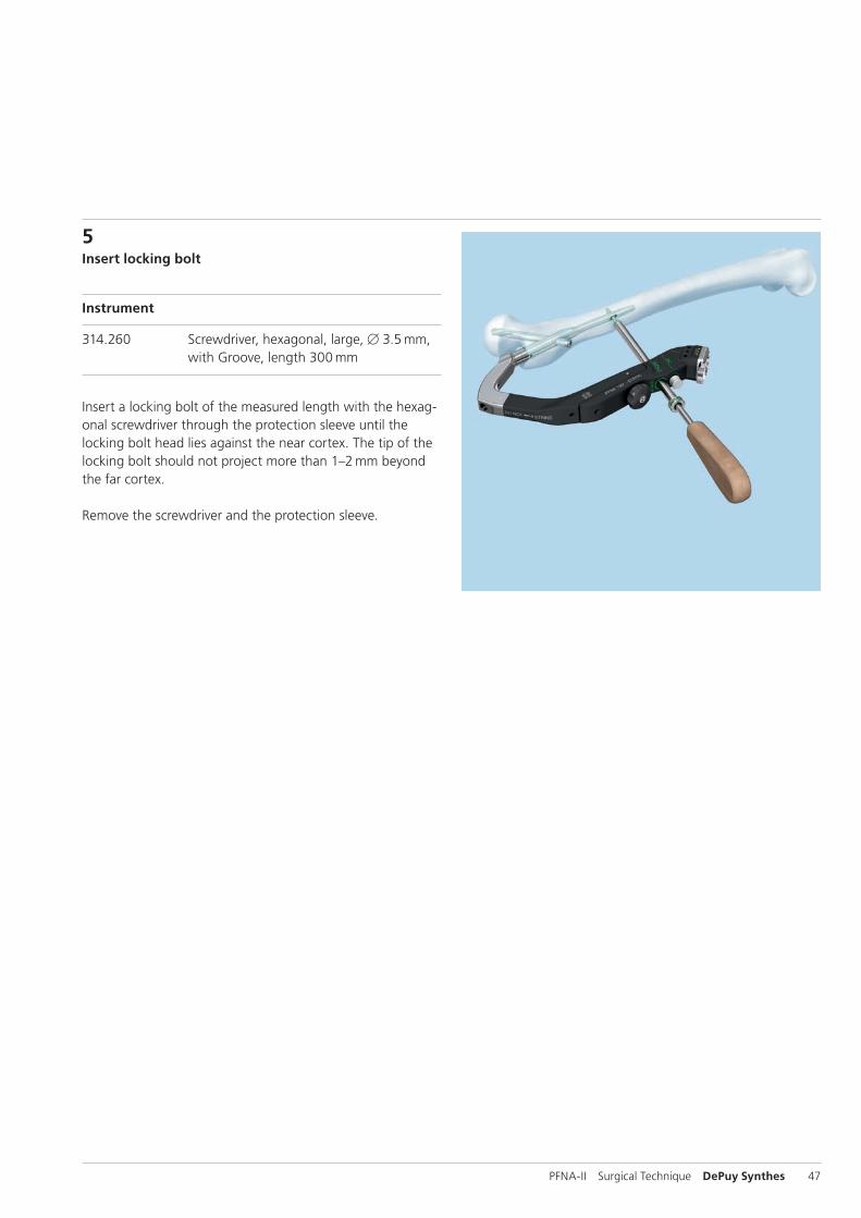
5Insert locking bolt
Instrument
314.260 Screwdriver, hexagonal, large, B 3.5 mm, with Groove, length 300 mm
Insert a locking bolt of the measured length with the hexag-onal screwdriver through the protection sleeve until the locking bolt head lies against the near cortex. The tip of the locking bolt should not project more than 1–2 mm beyond the far cortex.
Remove the screwdriver and the protection sleeve.
48 DePuy Synthes PFNA-II Surgical Technique
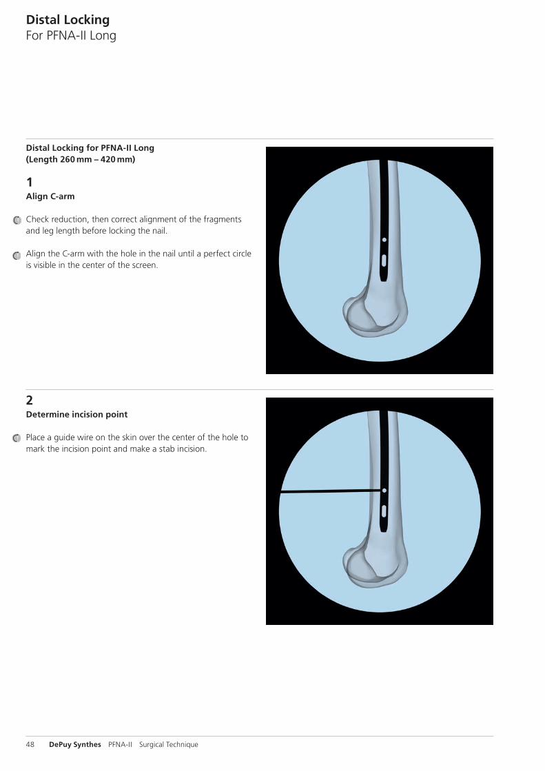
Distal Locking for PFNA-II Long (Length 260 mm – 420 mm)
1Align C-arm
Check reduction, then correct alignment of the fragments and leg length before locking the nail.
Align the C-arm with the hole in the nail until a perfect circle is visible in the center of the screen.
Distal LockingFor PFNA-II Long
2Determine incision point
Place a guide wire on the skin over the center of the hole to mark the incision point and make a stab incision.
PFNA-II Surgical Technique DePuy Synthes 49
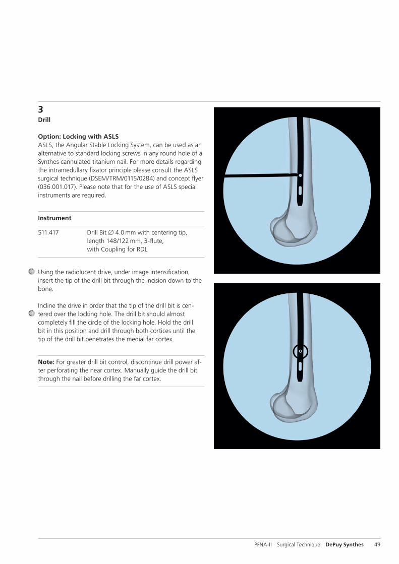
3Drill
Option: Locking with ASLSASLS, the Angular Stable Locking System, can be used as an alternative to standard locking screws in any round hole of a Synthes cannulated titanium nail. For more details regarding the intramedullary fixator principle please consult the ASLS surgical technique (DSEM/TRM/0115/0284) and concept flyer (036.001.017). Please note that for the use of ASLS special instruments are required.
Instrument
511.417 Drill Bit B 4.0 mm with centering tip, length 148/122 mm, 3-flute, with Coupling for RDL
Using the radiolucent drive, under image intensification, insert the tip of the drill bit through the incision down to the bone.
Incline the drive in order that the tip of the drill bit is cen-tered over the locking hole. The drill bit should almost completely fill the circle of the locking hole. Hold the drill bit in this position and drill through both cortices until the tip of the drill bit penetrates the medial far cortex.
Note: For greater drill bit control, discontinue drill power af-ter perforating the near cortex. Manually guide the drill bit through the nail before drilling the far cortex.
50 DePuy Synthes PFNA-II Surgical Technique
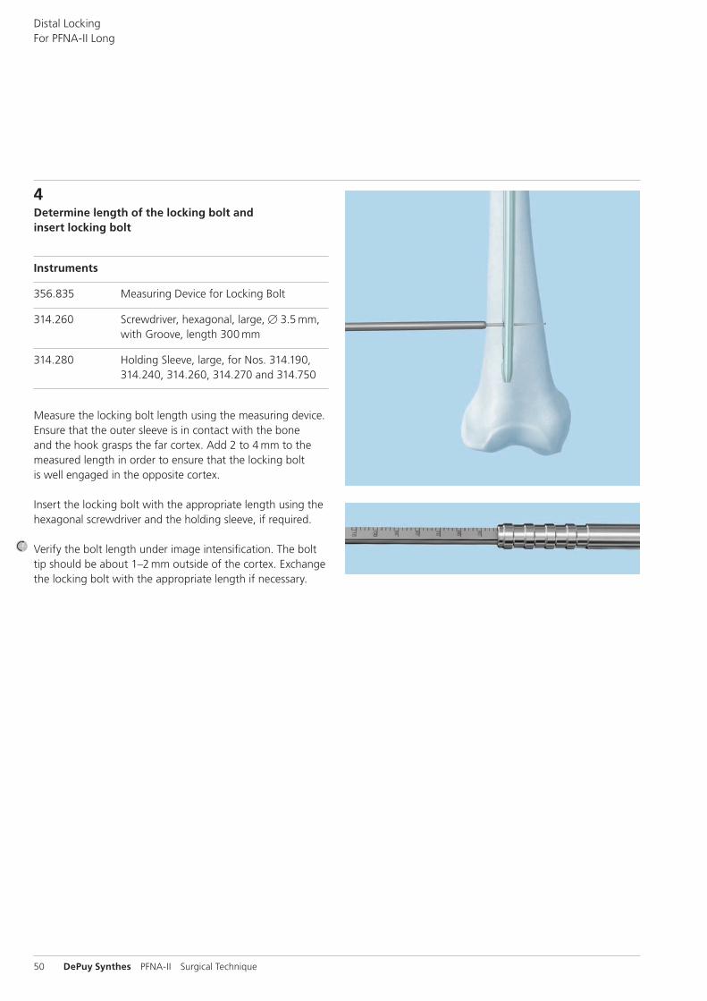
4Determine length of the locking bolt and insert locking bolt
Instruments
356.835 Measuring Device for Locking Bolt
314.260 Screwdriver, hexagonal, large, B 3.5 mm, with Groove, length 300 mm
314.280 Holding Sleeve, large, for Nos. 314.190, 314.240, 314.260, 314.270 and 314.750
Measure the locking bolt length using the measuring device. Ensure that the outer sleeve is in contact with the bone and the hook grasps the far cortex. Add 2 to 4 mm to the measured length in order to ensure that the locking bolt is well engaged in the opposite cortex.
Insert the locking bolt with the appropriate length using the hexagonal screwdriver and the holding sleeve, if required.
Verify the bolt length under image intensification. The bolt tip should be about 1–2 mm outside of the cortex. Exchange the locking bolt with the appropriate length if necessary.
Distal Locking For PFNA-II Long
PFNA-II Surgical Technique DePuy Synthes 51
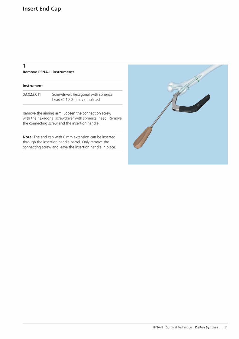
1Remove PFNA-II instruments
Instrument
03.023.011 Screwdriver, hexagonal with spherical head B 10.0 mm, cannulated
Remove the aiming arm. Loosen the connection screw with the hexagonal screwdriver with spherical head. Remove the connecting screw and the insertion handle.
Note: The end cap with 0 mm extension can be inserted through the insertion handle barrel. Only remove the connecting screw and leave the insertion handle in place.
Insert End Cap
52 DePuy Synthes PFNA-II Surgical Technique
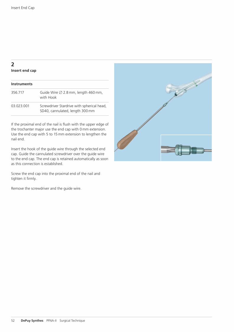
2Insert end cap
Instruments
356.717 Guide Wire B 2.8 mm, length 460 mm, with Hook
03.023.001 Screwdriver Stardrive with spherical head, SD40, cannulated, length 300 mm
If the proximal end of the nail is flush with the upper edge of the trochanter major use the end cap with 0 mm extension. Use the end cap with 5 to 15 mm extension to lengthen the nail end.
Insert the hook of the guide wire through the selected end cap. Guide the cannulated screwdriver over the guide wire to the end cap. The end cap is retained automatically as soon as this connection is established.
Screw the end cap into the proximal end of the nail and tighten it firmly.
Remove the screwdriver and the guide wire.
Insert End Cap
PFNA-II Surgical Technique DePuy Synthes 53
Implant Removal
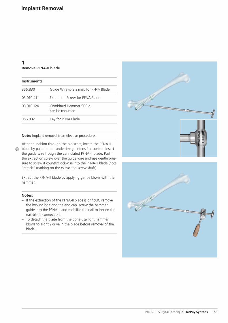
1Remove PFNA-II blade
Instruments
356.830 Guide Wire B 3.2 mm, for PFNA Blade
03.010.411 Extraction Screw for PFNA Blade
03.010.124 Combined Hammer 500 g, can be mounted
356.832 Key for PFNA Blade
Note: Implant removal is an elective procedure.
After an incision through the old scars, locate the PFNA-II blade by palpation or under image intensifier control. Insert the guide wire trough the cannulated PFNA-II blade. Push the extraction screw over the guide wire and use gentle pres-sure to screw it counterclockwise into the PFNA-II blade (note ”attach” marking on the extraction screw shaft).
Extract the PFNA-II blade by applying gentle blows with the hammer.
Notes: – If the extraction of the PFNA-II blade is difficult, remove
the locking bolt and the end cap, screw the hammer guide into the PFNA-II and mobilize the nail to loosen the nail-blade connection.
– To detach the blade from the bone use light hammer blows to slightly drive in the blade before removal of the blade.
54 DePuy Synthes PFNA-II Surgical Technique
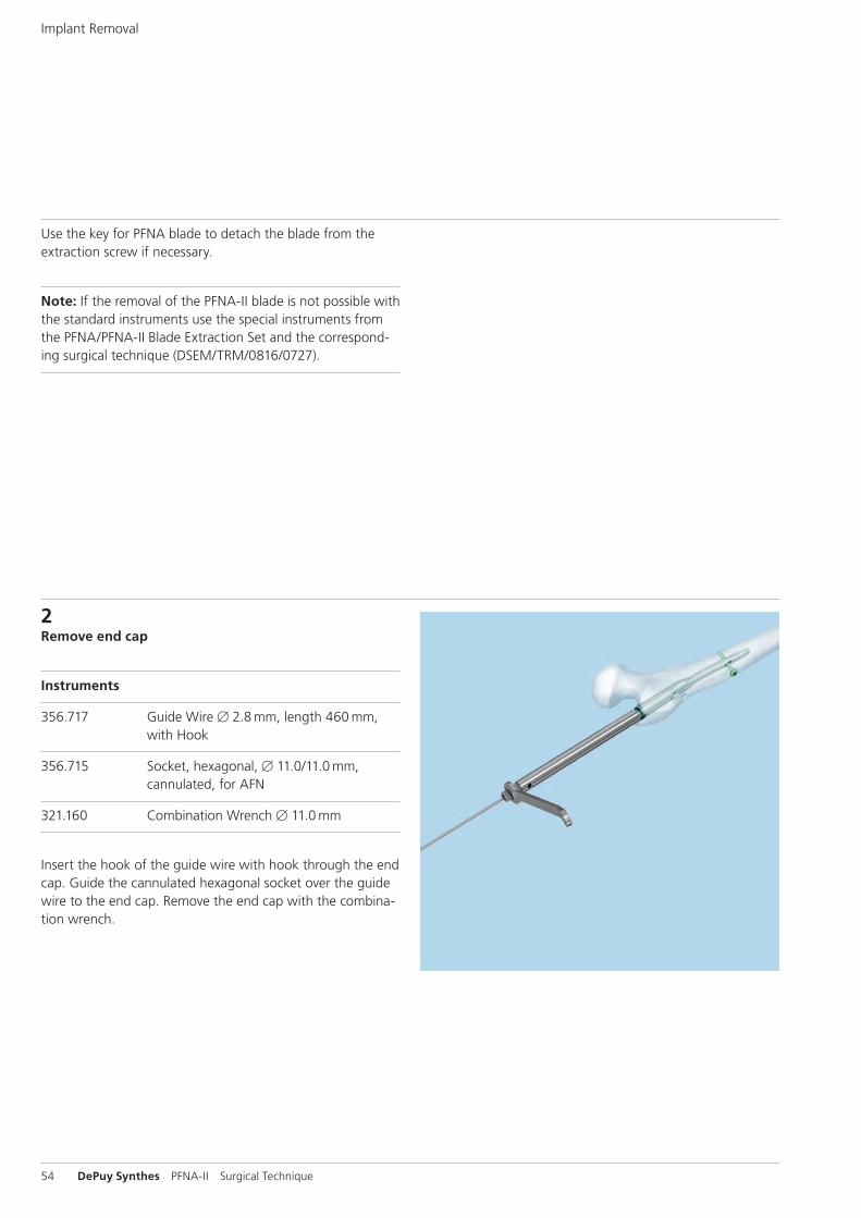
2Remove end cap
Instruments
356.717 Guide Wire B 2.8 mm, length 460 mm, with Hook
356.715 Socket, hexagonal, B 11.0/11.0 mm, cannulated, for AFN
321.160 Combination Wrench B 11.0 mm
Insert the hook of the guide wire with hook through the end cap. Guide the cannulated hexagonal socket over the guide wire to the end cap. Remove the end cap with the combina-tion wrench.
Use the key for PFNA blade to detach the blade from the extraction screw if necessary.
Note: If the removal of the PFNA-II blade is not possible with the standard instruments use the special instruments from the PFNA/PFNA-II Blade Extraction Set and the correspond-ing surgical technique (DSEM/TRM/0816/0727).
Implant Removal
PFNA-II Surgical Technique DePuy Synthes 55
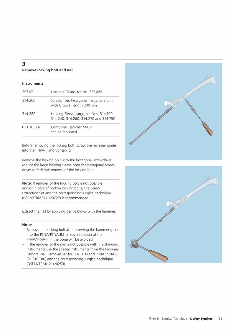
3Remove locking bolt and nail
Instruments
357.071 Hammer Guide, for No. 357.026
314.260 Screwdriver, hexagonal, large, B 3.5 mm, with Groove, length 300 mm
314.280 Holding Sleeve, large, for Nos. 314.190, 314.240, 314.260, 314.270 and 314.750
03.010.124 Combined Hammer 500 g, can be mounted
Before removing the locking bolt, screw the hammer guide into the PFNA-II and tighten it.
Remove the locking bolt with the hexagonal screwdriver. Mount the large holding sleeve onto the hexagonal screw-driver to facilitate removal of the locking bolt.
Note: If removal of the locking bolt is not possible and/or in case of broken locking bolts, the Screw Extraction Set and the corresponding surgical technique (DSEM/TRM/0614/0727) is recommended.
Extract the nail by applying gentle blows with the hammer.
Notes: – Remove the locking bolt after screwing the hammer guide
into the PFNA/PFNA-II.Thereby a rotation of the PFNA/PFNA-II in the bone will be avoided.
– If the removal of the nail is not possible with the standard instruments use the special instruments from the Proximal Femoral Nail Removal Set for PFN, TFN and PFNA/PFNA-II (01.010.180) and the corresponding surgical technique (DSEM/TRM/1214/0253).
56 DePuy Synthes PFNA-II Surgical Technique
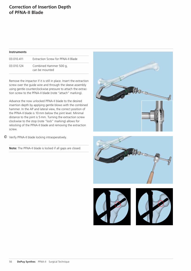
Instruments
03.010.411 Extraction Screw for PFNA-II Blade
03.010.124 Combined Hammer 500 g, can be mounted
Remove the impactor if it is still in place. Insert the extraction screw over the guide wire and through the sleeve assembly using gentle counterclockwise pressure to attach the extrac-tion screw to the PFNA-II blade (note “attach” marking).
Advance the now unlocked PFNA-II blade to the desired insertion depth by applying gentle blows with the combined hammer. In the AP and lateral view, the correct position of the PFNA-II blade is 10 mm below the joint level. Minimal distance to the joint is 5 mm. Turning the extraction screw clockwise to the stop (note “lock” marking) allows for relocking of the PFNA-II blade and removing the extraction screw.
Verify PFNA-II blade locking intraoperatively.
Note: The PFNA-II blade is locked if all gaps are closed.
Correction of Insertion Depth of PFNA-II Blade
PFNA-II Surgical Technique DePuy Synthes 57
Cleaning
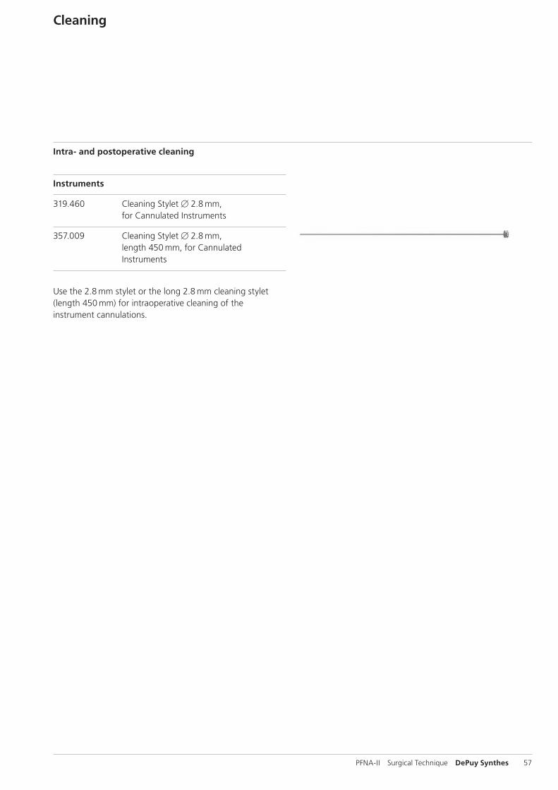
Intra- and postoperative cleaning
Instruments
319.460 Cleaning Stylet B 2.8 mm, for Cannulated Instruments
357.009 Cleaning Stylet B 2.8 mm, length 450 mm, for Cannulated Instruments
Use the 2.8 mm stylet or the long 2.8 mm cleaning stylet (length 450 mm) for intraoperative cleaning of the instrument cannulations.
58 DePuy Synthes PFNA-II Surgical Technique
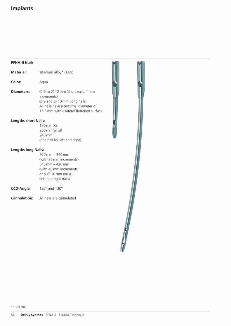
PFNA-II Nails
Material: Titanium alloy* (TAN)
Color: Aqua
Diameters: B 9 to B 12 mm (short nails, 1 mm increments) B 9 and B 10 mm (long nails) All nails have a proximal diameter of 16.5 mm with a lateral flattened surface
Lengths short Nails: 170 mm XS
200 mm Small 240 mm (one nail for left and right)
Lengths long Nails: 260 mm – 340 mm
(with 20 mm increments) 340 mm – 420 mm (with 40 mm increments, only B 10 mm nails) (left and right nails)
CCD-Angle: 125° and 130°
Cannulation: All nails are cannulated
Implants
*Ti-6Al-7Nb
PFNA-II Surgical Technique DePuy Synthes 59
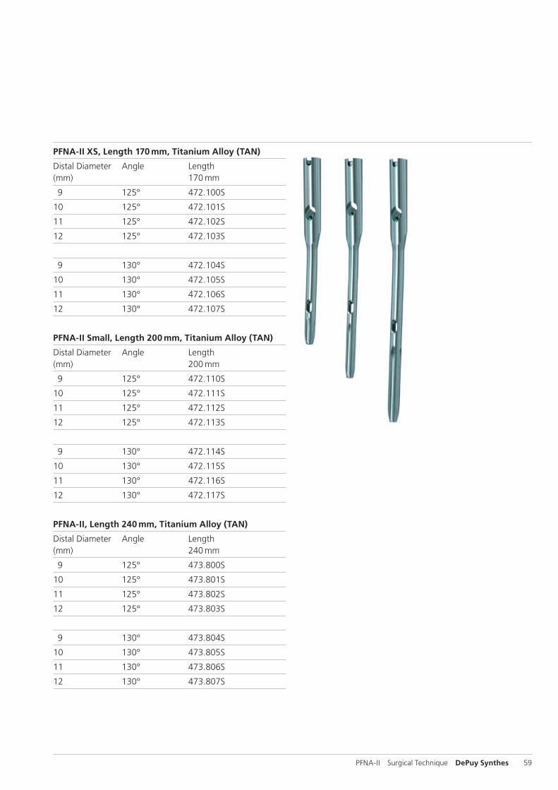
PFNA-II XS, Length 170 mm, Titanium Alloy (TAN)
Distal Diameter Angle Length(mm) 170 mm
9 125° 472.100S
10 125° 472.101S
11 125° 472.102S
12 125° 472.103S
9 130° 472.104S
10 130° 472.105S
11 130° 472.106S
12 130° 472.107S
PFNA-II Small, Length 200 mm, Titanium Alloy (TAN)
Distal Diameter Angle Length(mm) 200 mm
9 125° 472.110S
10 125° 472.111S
11 125° 472.112S
12 125° 472.113S
9 130° 472.114S
10 130° 472.115S
11 130° 472.116S
12 130° 472.117S
PFNA-II, Length 240 mm, Titanium Alloy (TAN)
Distal Diameter Angle Length(mm) 240 mm
9 125° 473.800S
10 125° 473.801S
11 125° 473.802S
12 125° 473.803S
9 130° 473.804S
10 130° 473.805S
11 130° 473.806S
12 130° 473.807S
60 DePuy Synthes PFNA-II Surgical Technique
Implants
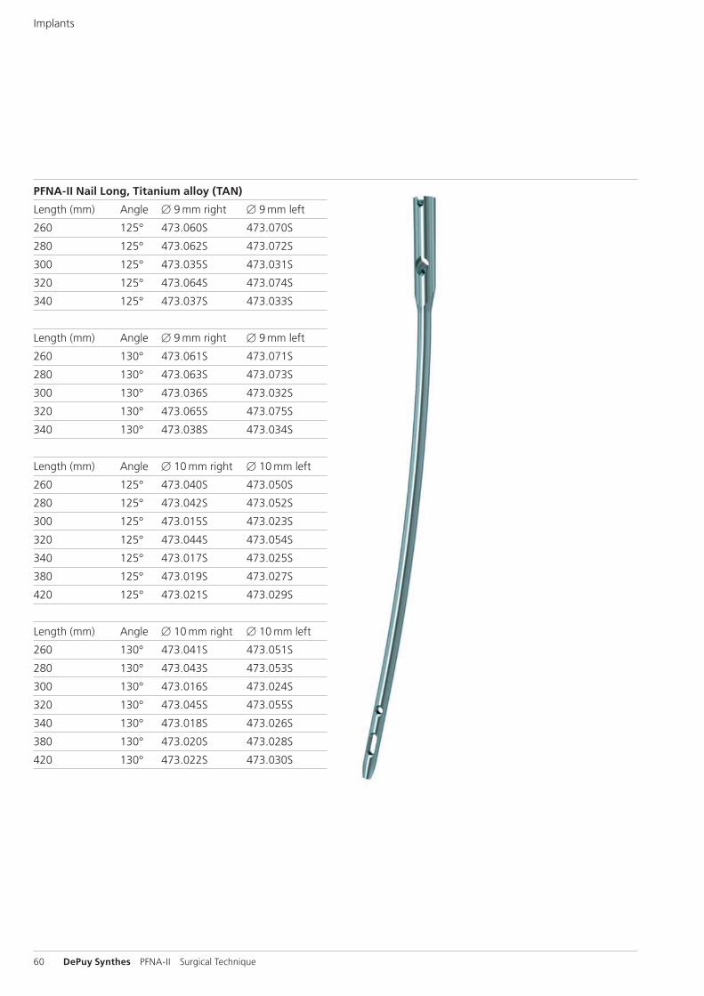
PFNA-II Nail Long, Titanium alloy (TAN)
Length (mm) Angle B 9 mm right B 9 mm left
260 125° 473.060S 473.070S
280 125° 473.062S 473.072S
300 125° 473.035S 473.031S
320 125° 473.064S 473.074S
340 125° 473.037S 473.033S
Length (mm) Angle B 9 mm right B 9 mm left
260 130° 473.061S 473.071S
280 130° 473.063S 473.073S
300 130° 473.036S 473.032S
320 130° 473.065S 473.075S
340 130° 473.038S 473.034S
Length (mm) Angle B 10 mm right B 10 mm left
260 125° 473.040S 473.050S
280 125° 473.042S 473.052S
300 125° 473.015S 473.023S
320 125° 473.044S 473.054S
340 125° 473.017S 473.025S
380 125° 473.019S 473.027S
420 125° 473.021S 473.029S
Length (mm) Angle B 10 mm right B 10 mm left
260 130° 473.041S 473.051S
280 130° 473.043S 473.053S
300 130° 473.016S 473.024S
320 130° 473.045S 473.055S
340 130° 473.018S 473.026S
380 130° 473.020S 473.028S
420 130° 473.022S 473.030S
PFNA-II Surgical Technique DePuy Synthes 61
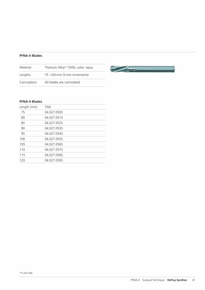
PFNA-II Blades
Material: Titanium Alloy* (TAN), color: aqua
Lengths: 75 –120 mm (5 mm increments)
Cannulation: All blades are cannulated
PFNA-II Blades
Length (mm) TAN
75 04.027.050S
80 04.027.051S
85 04.027.052S
90 04.027.053S
95 04.027.054S
100 04.027.055S
105 04.027.056S
110 04.027.057S
115 04.027.058S
120 04.027.059S
*Ti-6Al-7Nb
62 DePuy Synthes PFNA-II Surgical Technique
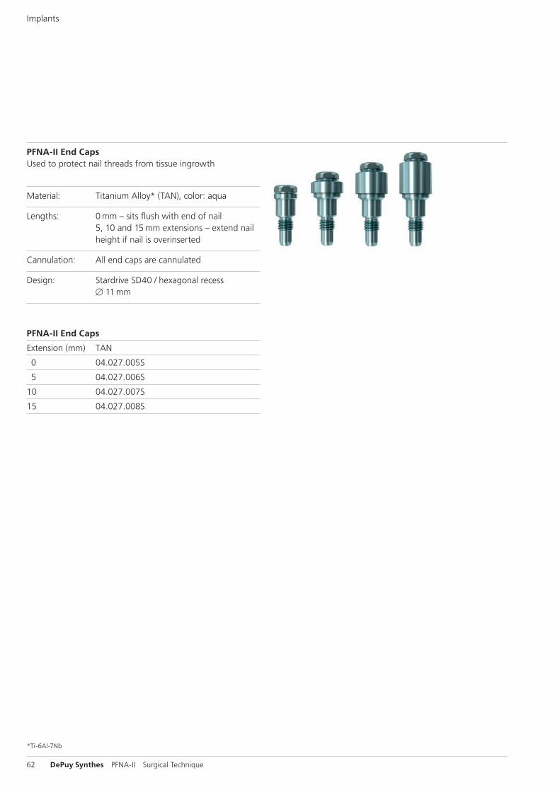
PFNA-II End CapsUsed to protect nail threads from tissue ingrowth
Material: Titanium Alloy* (TAN), color: aqua
Lengths: 0 mm – sits flush with end of nail 5, 10 and 15 mm extensions – extend nail height if nail is overinserted
Cannulation: All end caps are cannulated
Design: Stardrive SD40 / hexagonal recess B 11 mm
Implants
PFNA-II End Caps
Extension (mm) TAN
0 04.027.005S
5 04.027.006S
10 04.027.007S
15 04.027.008S
*Ti-6Al-7Nb
PFNA-II Surgical Technique DePuy Synthes 63
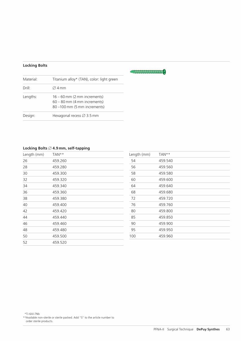
Locking Bolts
Material: Titanium alloy* (TAN), color: light green
Drill: B 4 mm
Lengths: 16 – 60 mm (2 mm increments) 60 – 80 mm (4 mm increments) 80 –100 mm (5 mm increments)
Design: Hexagonal recess B 3.5 mm
Length (mm) TAN**
54 459.540
56 459.560
58 459.580
60 459.600
64 459.640
68 459.680
72 459.720
76 459.760
80 459.800
85 459.850
90 459.900
95 459.950
100 459.960
Locking Bolts B 4.9 mm, self-tapping
Length (mm) TAN**
26 459.260
28 459.280
30 459.300
32 459.320
34 459.340
36 459.360
38 459.380
40 459.400
42 459.420
44 459.440
46 459.460
48 459.480
50 459.500
52 459.520
*Ti-6Al-7Nb** Available non-sterile or sterile packed. Add “S” to the article number to
order sterile products.
64 DePuy Synthes PFNA-II Surgical Technique
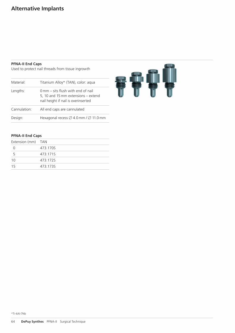
PFNA-II End CapsUsed to protect nail threads from tissue ingrowth
Material: Titanium Alloy* (TAN), color: aqua
Lengths: 0 mm – sits flush with end of nail 5, 10 and 15 mm extensions – extend nail height if nail is overinserted
Cannulation: All end caps are cannulated
Design: Hexagonal recess B 4.0 mm / B 11.0 mm
PFNA-II End Caps
Extension (mm) TAN
0 473.170S
5 473.171S
10 473.172S
15 473.173S
Alternative Implants
*Ti-6Al-7Nb
PFNA-II Surgical Technique DePuy Synthes 65
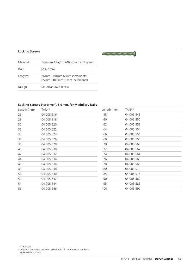
Locking Screws
Material: Titanium Alloy* (TAN), color: light green
Drill: B 4.2 mm
Lengths: 26 mm – 80 mm (2 mm increments) 85 mm –100 mm (5 mm increments)
Design: Stardrive SD25 recess
Length (mm) TAN**
58 04.005.548
60 04.005.550
62 04.005.552
64 04.005.554
66 04.005.556
68 04.005.558
70 04.005.560
72 04.005.562
74 04.005.564
76 04.005.566
78 04.005.568
80 04.005.570
85 04.005.575
90 04.005.580
95 04.005.585
100 04.005.590
*Ti-6Al-7Nb** Available non-sterile or sterile packed. Add “S” to the article number to
order sterile products.
Locking Screws Stardrive B 5.0 mm, for Medullary Nails
Length (mm) TAN**
26 04.005.516
28 04.005.518
30 04.005.520
32 04.005.522
34 04.005.524
36 04.005.526
38 04.005.528
40 04.005.530
42 04.005.532
44 04.005.534
46 04.005.536
48 04.005.538
50 04.005.540
52 04.005.542
54 04.005.544
56 04.005.546
66 DePuy Synthes PFNA-II Surgical Technique
309.602 Radiographic Ruler for PFNA
314.260 Screwdriver, hexagonal, large, B 3.5 mm, with Groove, length 300 mm
314.280 Holding Sleeve, large, for Nos. 314.190, 314.240, 314.260, 314.270 and 314.750
321.160 Combination Wrench B 11.0 mm
321.170 Pin Wrench B 4.5 mm, length 120 mm
356.715 Socket, hexagonal, B 11.0/11.0 mm, cannulated, for AFN
Instruments
356.717 Guide Wire B 2.8 mm, length 460 mm, with Hook
356.817 Buttress/Compression Nut, for PFNA Blade
314.050 Screwdriver, hexagonal, cannulated, for Cannulated Screws B 6.5 and 7.3 mm
PFNA-II Surgical Technique DePuy Synthes 67
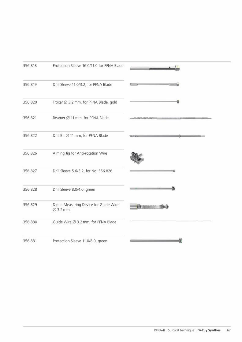
356.818 Protection Sleeve 16.0/11.0 for PFNA Blade
356.819 Drill Sleeve 11.0/3.2, for PFNA Blade
356.820 Trocar B 3.2 mm, for PFNA Blade, gold
356.821 Reamer B 11 mm, for PFNA Blade
356.822 Drill Bit B 11 mm, for PFNA Blade
356.826 Aiming Jig for Anti-rotation Wire
356.827 Drill Sleeve 5.6/3.2, for No. 356.826
356.828 Drill Sleeve 8.0/4.0, green
356.829 Direct Measuring Device for Guide Wire B 3.2 mm
356.830 Guide Wire B 3.2 mm, for PFNA Blade
356.831 Protection Sleeve 11.0/8.0, green
68 DePuy Synthes PFNA-II Surgical Technique
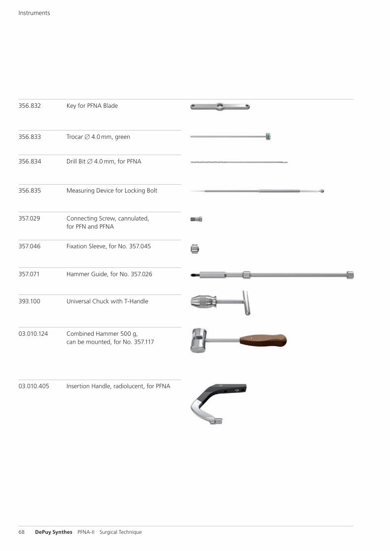
356.832 Key for PFNA Blade
356.833 Trocar B 4.0 mm, green
356.834 Drill Bit B 4.0 mm, for PFNA
356.835 Measuring Device for Locking Bolt
357.029 Connecting Screw, cannulated, for PFN and PFNA
357.046 Fixation Sleeve, for No. 357.045
357.071 Hammer Guide, for No. 357.026
393.100 Universal Chuck with T-Handle
03.010.124 Combined Hammer 500 g, can be mounted, for No. 357.117
03.010.405 Insertion Handle, radiolucent, for PFNA
Instruments
PFNA-II Surgical Technique DePuy Synthes 69
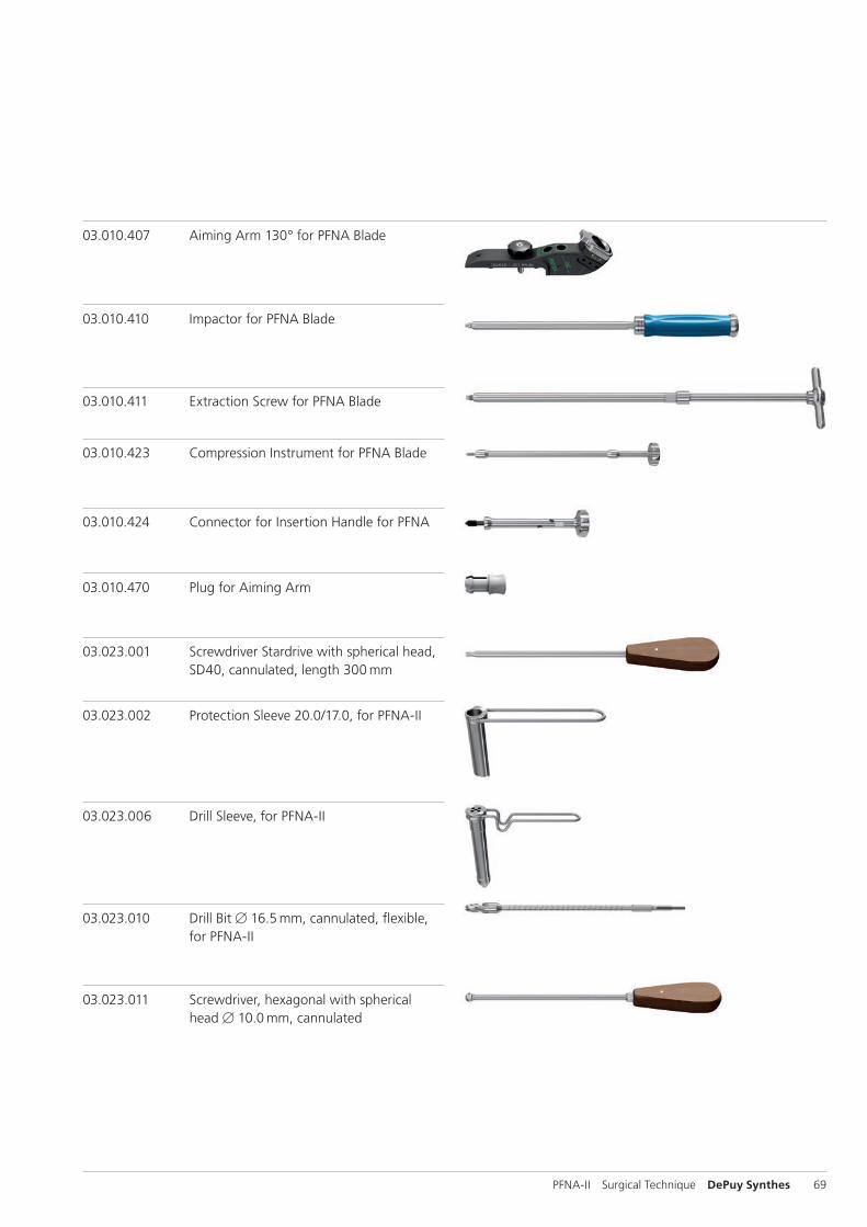
03.023.001 Screwdriver Stardrive with spherical head, SD40, cannulated, length 300 mm
03.023.011 Screwdriver, hexagonal with spherical head B 10.0 mm, cannulated
03.010.407 Aiming Arm 130° for PFNA Blade
03.010.410 Impactor for PFNA Blade
03.010.411 Extraction Screw for PFNA Blade
03.010.423 Compression Instrument for PFNA Blade
03.010.424 Connector for Insertion Handle for PFNA
03.010.470 Plug for Aiming Arm
03.023.002 Protection Sleeve 20.0/17.0, for PFNA-II
03.023.006 Drill Sleeve, for PFNA-II
03.023.010 Drill Bit B 16.5 mm, cannulated, flexible, for PFNA-II
70 DePuy Synthes PFNA-II Surgical Technique
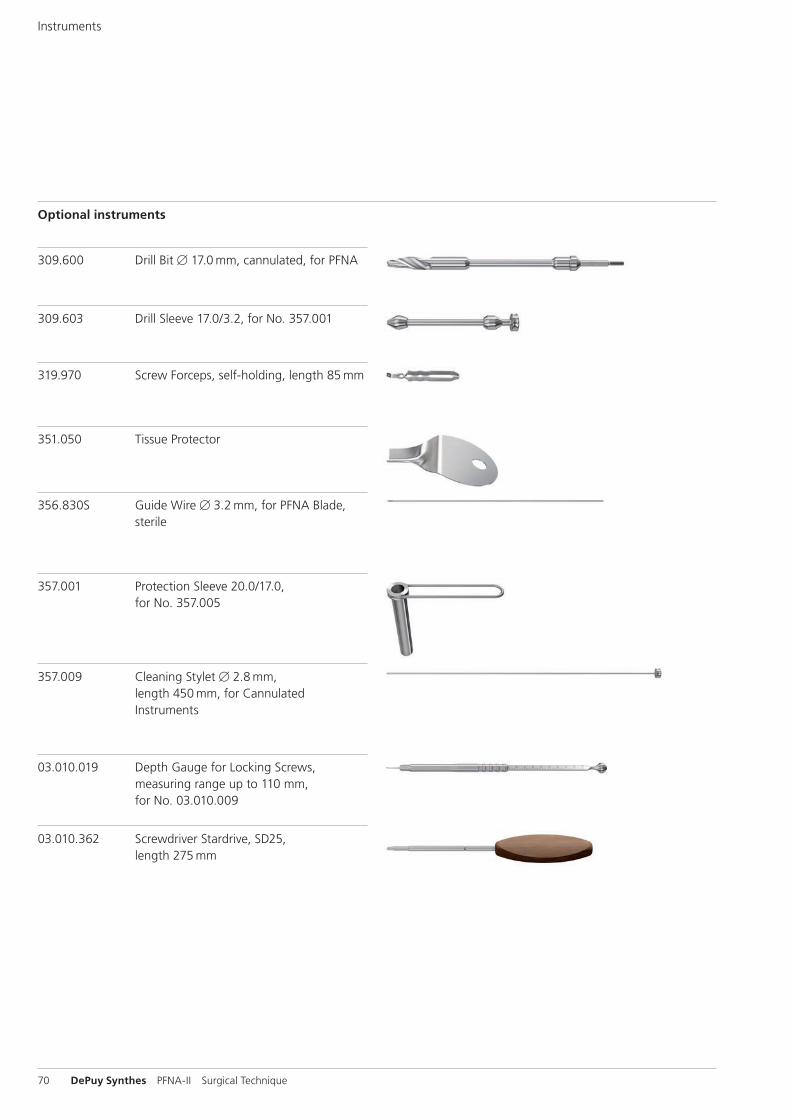
Optional instruments
351.050 Tissue Protector
356.830S Guide Wire B 3.2 mm, for PFNA Blade, sterile
357.009 Cleaning Stylet B 2.8 mm, length 450 mm, for Cannulated Instruments
319.970 Screw Forceps, self-holding, length 85 mm
03.010.019 Depth Gauge for Locking Screws, measuring range up to 110 mm, for No. 03.010.009
03.010.362 Screwdriver Stardrive, SD25, length 275 mm
309.600 Drill Bit B 17.0 mm, cannulated, for PFNA
309.603 Drill Sleeve 17.0/3.2, for No. 357.001
357.001 Protection Sleeve 20.0/17.0, for No. 357.005
Instruments
PFNA-II Surgical Technique DePuy Synthes 71
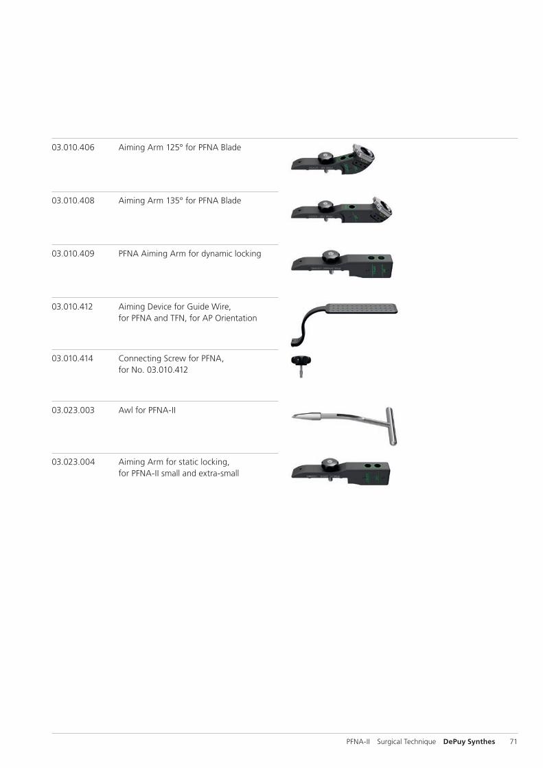
03.023.004 Aiming Arm for static locking, for PFNA-II small and extra-small
03.023.003 Awl for PFNA-II
03.010.414 Connecting Screw for PFNA, for No. 03.010.412
03.010.409 PFNA Aiming Arm for dynamic locking
03.010.412 Aiming Device for Guide Wire, for PFNA and TFN, for AP Orientation
03.010.408 Aiming Arm 135° for PFNA Blade
03.010.406 Aiming Arm 125° for PFNA Blade
72 DePuy Synthes PFNA-II Surgical Technique
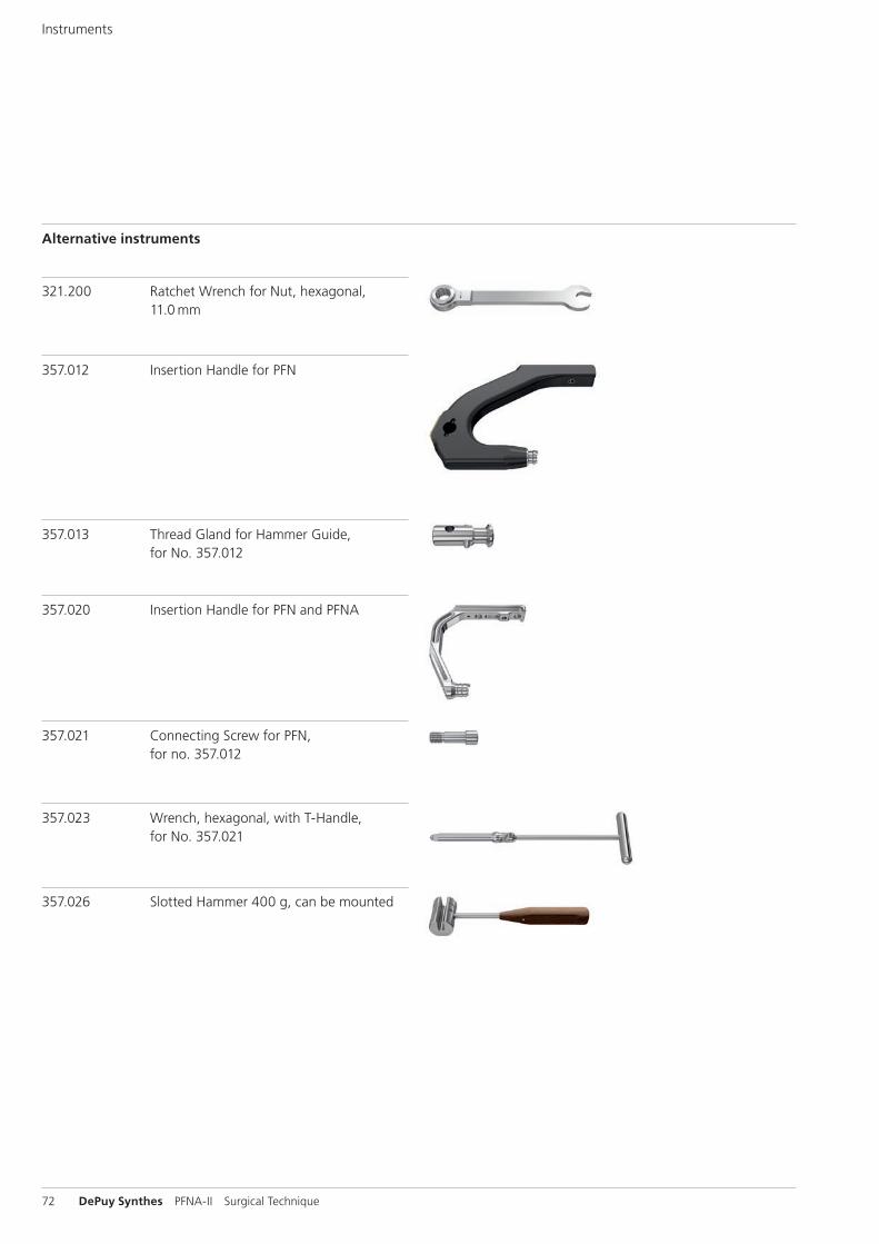
Alternative instruments
357.012 Insertion Handle for PFN
321.200 Ratchet Wrench for Nut, hexagonal, 11.0 mm
Instruments
357.020 Insertion Handle for PFN and PFNA
357.021 Connecting Screw for PFN, for no. 357.012
357.023 Wrench, hexagonal, with T-Handle, for No. 357.021
357.026 Slotted Hammer 400 g, can be mounted
357.013 Thread Gland for Hammer Guide, for No. 357.012
PFNA-II Surgical Technique DePuy Synthes 73
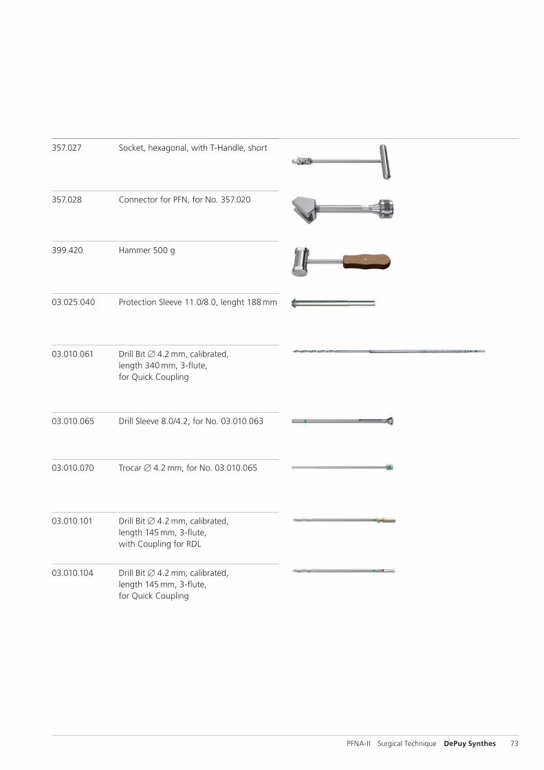
357.027 Socket, hexagonal, with T-Handle, short
357.028 Connector for PFN, for No. 357.020
399.420 Hammer 500 g
03.025.040 Protection Sleeve 11.0/8.0, lenght 188 mm
03.010.061 Drill Bit B 4.2 mm, calibrated, length 340 mm, 3-flute, for Quick Coupling
03.010.065 Drill Sleeve 8.0/4.2, for No. 03.010.063
03.010.070 Trocar B 4.2 mm, for No. 03.010.065
03.010.101 Drill Bit B 4.2 mm, calibrated, length 145 mm, 3-flute, with Coupling for RDL
03.010.104 Drill Bit B 4.2 mm, calibrated, length 145 mm, 3-flute, for Quick Coupling
74 DePuy Synthes PFNA-II Surgical Technique
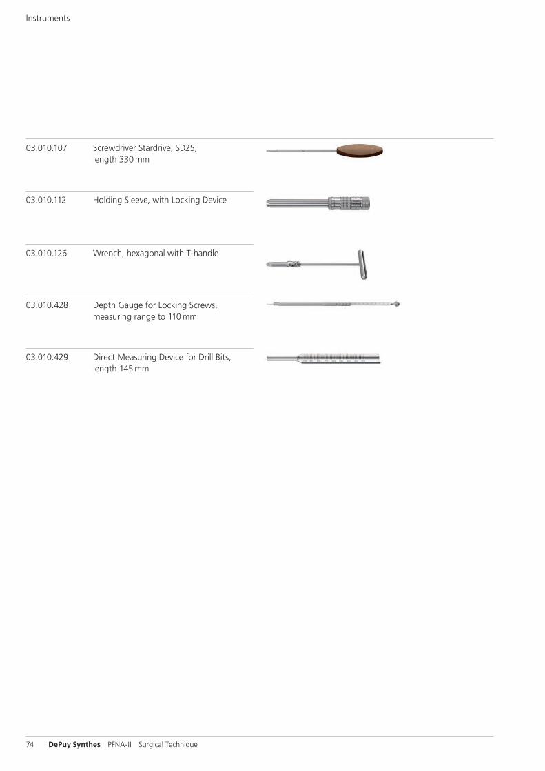
03.010.126 Wrench, hexagonal with T-handle
03.010.428 Depth Gauge for Locking Screws, measuring range to 110 mm
03.010.429 Direct Measuring Device for Drill Bits, length 145 mm
03.010.107 Screwdriver Stardrive, SD25, length 330 mm
03.010.112 Holding Sleeve, with Locking Device
Instruments
PFNA-II Surgical Technique DePuy Synthes 75
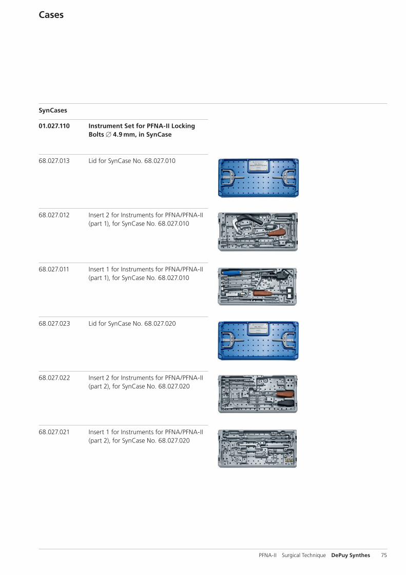
01.027.110 Instrument Set for PFNA-II Locking Bolts B 4.9 mm, in SynCase
68.027.013 Lid for SynCase No. 68.027.010
68.027.012 Insert 2 for Instruments for PFNA/PFNA-II (part 1), for SynCase No. 68.027.010
68.027.011 Insert 1 for Instruments for PFNA/PFNA-II (part 1), for SynCase No. 68.027.010
68.027.023 Lid for SynCase No. 68.027.020
68.027.022 Insert 2 for Instruments for PFNA/PFNA-II (part 2), for SynCase No. 68.027.020
68.027.021 Insert 1 for Instruments for PFNA/PFNA-II (part 2), for SynCase No. 68.027.020
SynCases
Cases
76 DePuy Synthes PFNA-II Surgical Technique
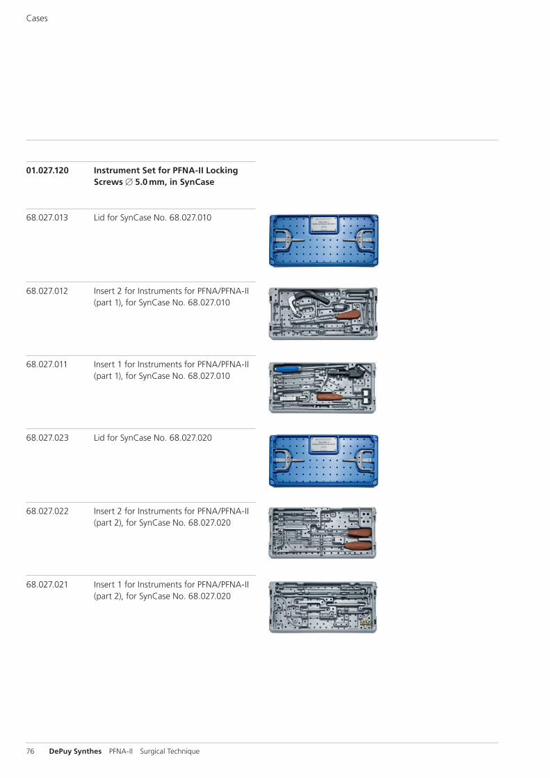
68.027.013 Lid for SynCase No. 68.027.010
68.027.012 Insert 2 for Instruments for PFNA/PFNA-II (part 1), for SynCase No. 68.027.010
68.027.011 Insert 1 for Instruments for PFNA/PFNA-II (part 1), for SynCase No. 68.027.010
68.027.023 Lid for SynCase No. 68.027.020
68.027.022 Insert 2 for Instruments for PFNA/PFNA-II (part 2), for SynCase No. 68.027.020
68.027.021 Insert 1 for Instruments for PFNA/PFNA-II (part 2), for SynCase No. 68.027.020
01.027.120 Instrument Set for PFNA-II Locking Screws B 5.0 mm, in SynCase
Cases
PFNA-II Surgical Technique DePuy Synthes 77
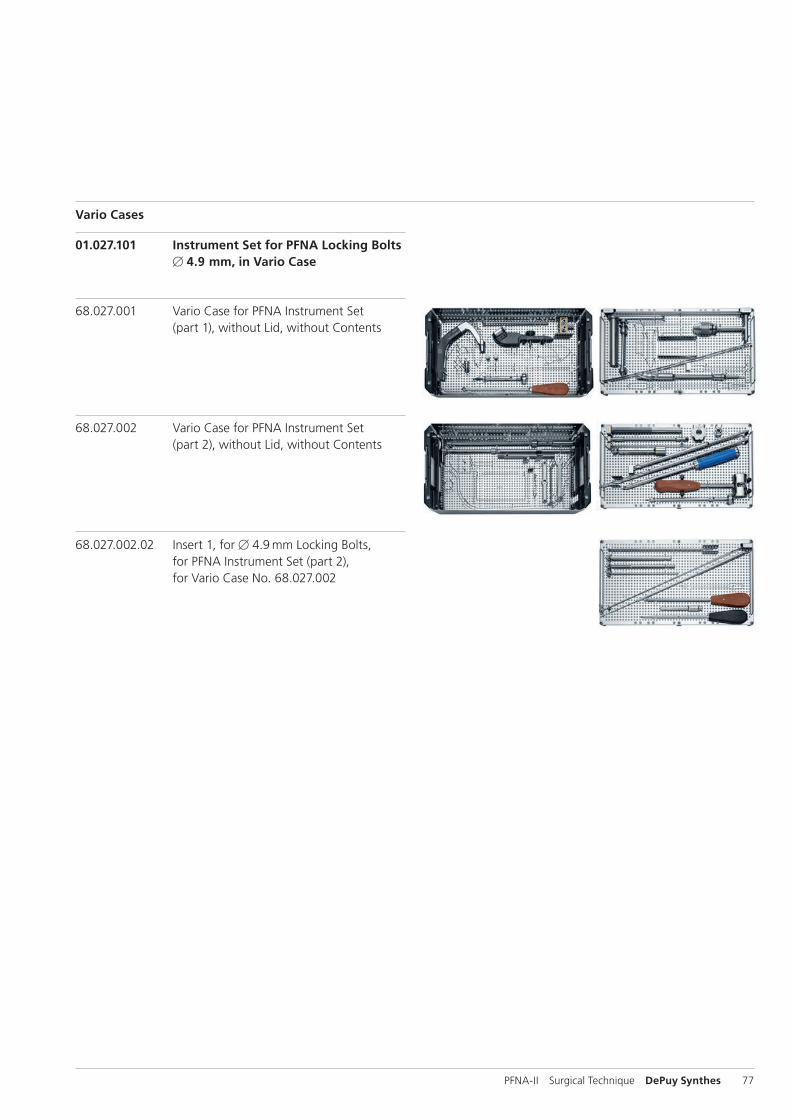
01.027.101 Instrument Set for PFNA Locking Bolts B 4.9 mm, in Vario Case
Vario Cases
68.027.001 Vario Case for PFNA Instrument Set (part 1), without Lid, without Contents
68.027.002 Vario Case for PFNA Instrument Set (part 2), without Lid, without Contents
68.027.002.02 Insert 1, for B 4.9 mm Locking Bolts, for PFNA Instrument Set (part 2), for Vario Case No. 68.027.002
78 DePuy Synthes PFNA-II Surgical Technique
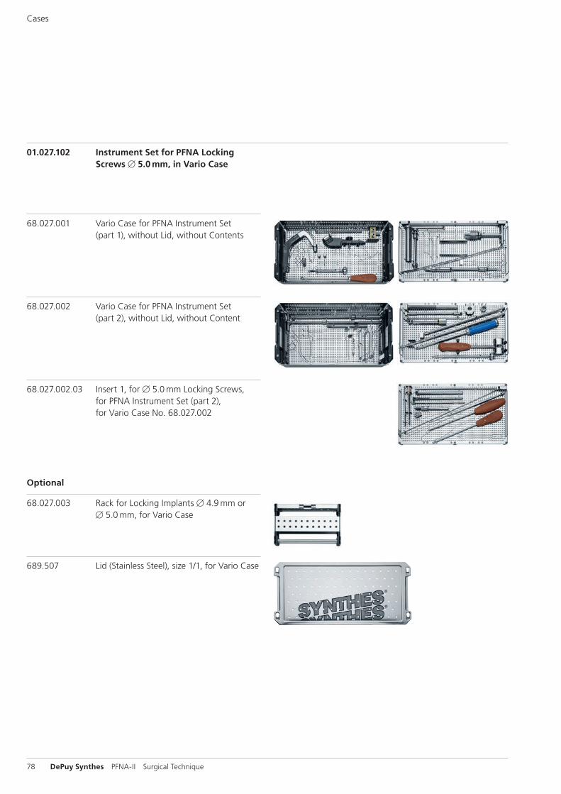
01.027.102 Instrument Set for PFNA Locking Screws B 5.0 mm, in Vario Case
68.027.001 Vario Case for PFNA Instrument Set (part 1), without Lid, without Contents
68.027.002 Vario Case for PFNA Instrument Set (part 2), without Lid, without Content
68.027.002.03 Insert 1, for B 5.0 mm Locking Screws, for PFNA Instrument Set (part 2), for Vario Case No. 68.027.002
Optional
68.027.003 Rack for Locking Implants B 4.9 mm or B 5.0 mm, for Vario Case
689.507 Lid (Stainless Steel), size 1/1, for Vario Case
Cases
PFNA-II Surgical Technique DePuy Synthes 79
MRI Information
Torque, Displacement and Image Artifacts according to ASTM F 2213-06, ASTM F 2052-06e1 and ASTM F 2119-07Non-clinical testing of worst case scenario in a 3 T MRI system did not reveal any relevant torque or displacement of the construct for an experimentally measured local spatial gradient of the magnetic field of 3.69 T/m. The largest image artifact extended approximately 169 mm from the construct when scanned using the Gradient Echo (GE). Testing was conducted on a 3 T MRI system.
Radio-Frequency-(RF-)induced heating according to ASTM F 2182-11aNon-clinical electromagnetic and thermal testing of worst case scenario lead to peak temperature rise of 9.5 °C with an average temperature rise of 6.6 °C (1.5 T) and a peak temperature rise of 5.9 °C (3 T) under MRI Conditions using RF Coils (whole body averaged specific absorption rate [SAR] of 2 W/kg for 6 minutes [1.5 T] and for 15 minutes [3 T]).
Precautions: The above mentioned test relies on non-clini-cal testing. The actual temperature rise in the patient will depend on a variety of factors beyond the SAR and time of RF application. Thus, it is recommended to pay particular attention to the following points: – It is recommended to thoroughly monitor patients under-
going MR scanning for perceived temperature and/or pain sensations.
– Patients with impaired thermoregulation or temperature sensation should be excluded from MR scanning proce-dures.
– Generally, it is recommended to use a MR system with low field strength in the presence of conductive implants. The employed specific absorption rate (SAR) should be reduced as far as possible.
– Using the ventilation system may further contribute to reduce temperature increase in the body.


0123
Synthes GmbHEimattstrasse 34436 OberdorfSwitzerlandTel: +41 61 965 61 11Fax: +41 61 965 66 00www.depuysynthes.com
Not all products are currently available in all markets.
This publication is not intended for distribution in the USA.
All surgical techniques are available as PDF files at www.depuysynthes.com/ifu ©
DeP
uy S
ynth
es T
raum
a, a
div
isio
n of
Syn
thes
Gm
bH. 2
016.
A
ll rig
hts
rese
rved
. 03
6.0
00.
035
DSE
M/T
RM
/071
4/01
09(4
) 09
/16


![Untitled-3 [] · 2020. 1. 29. · Title: Untitled-3 Author: Siora Keywords: PFNA -II- Proximal Femoral Nail With Antirotation Blade Created Date: 11/21/2019 2:09:26 PM](https://img.pdfslide.us/doc/110x75/602c31ae9dcda045fb31de5a/untitled-3-2020-1-29-title-untitled-3-author-siora-keywords-pfna-ii-.jpg)