Embed Size (px)
Citation preview
Engineering Structures 31 (2009) 2215–2223
Contents lists available at ScienceDirect
Engineering Structures
journal homepage: www.elsevier.com/locate/engstruct
Review article
Simplified model for damage in squat RC shear walls
Edward D. Thomson a, María E. Perdomo b,∗, Ricardo Picón b, María E. Marante b, Julio Flórez-López c
a Structural Engineer, Fluor Canada Ltd, Suite 700, 1075 W Georgia St,Vancouver, Canadab Department of Structural Engineering, Lisandro Alvarado University, Barquisimeto, Venezuelac Department of Structural Engineering, University of Los Andes, Mérida, Venezuela
a r t i c l e i n f o
Article history:Received 5 December 2008Received in revised form29 March 2009Accepted 28 May 2009Available online 21 June 2009
Keywords:Shear wallsReinforced concreteEarthquake damageFracture mechanicsFinite elementsLumped plasticityElastoplasticity
a b s t r a c t
In this paper, a new simplified model for simulating damage of squat RC shear walls under lateral loads isproposed. This simplified model is based on damage and fracture mechanics. It describes the reduction instiffness and strength due to diagonal cracking, permanent deformations due to yielding of transversereinforcement and sliding across shear cracks. First, the analytical expressions are developed for theparticular case ofmonotonic loading. A yield function to describe permanent deformations due to yieldingof transverse reinforcement is proposed. Then, a crack resistance function, based on the Griffith criterion,is introduced and experimentally identified. Finally, the necessary analytical expressions are developedfor hysteretic behavior. The proposed numerical model is implemented in a commercial finite elementprogram and validated against experimental results. It is shown that the model can predict well theresponse of RC shear walls.
© 2009 Elsevier Ltd. All rights reserved.
Contents
1. Introduction.................................................................................................................................................................................................................... 22162. Model of monotonic behavior ....................................................................................................................................................................................... 2216
2.1. Element flexibility matrix ................................................................................................................................................................................. 22162.2. Evolution law of the permanent deformations................................................................................................................................................ 22172.3. Evolution law of the damage ............................................................................................................................................................................ 22172.4. Identification of the crack resistance function ................................................................................................................................................ 22172.5. Computation of the model parameters ............................................................................................................................................................ 22182.6. Numerical simulation ........................................................................................................................................................................................ 2219
3. Model for hysteretic behavior ....................................................................................................................................................................................... 22193.1. Unilateral behavior ............................................................................................................................................................................................ 22193.2. Pinching effects in shear walls .......................................................................................................................................................................... 2220
3.2.1. Sliding function of a shear crack........................................................................................................................................................ 22203.2.2. Computation of sliding shear parameters......................................................................................................................................... 2221
4. Numerical implementation and model validation....................................................................................................................................................... 22214.1. A finite element for squat RC shear walls ........................................................................................................................................................ 22214.2. Numerical simulations ...................................................................................................................................................................................... 2222
5. Conclusions..................................................................................................................................................................................................................... 2222Acknowledgements........................................................................................................................................................................................................ 2223Appendix. Notations ................................................................................................................................................................................................. 2223References....................................................................................................................................................................................................................... 2223
∗ Corresponding author. Tel.: +58 251 2529279; fax: +58 251 2592173.E-mail address:[email protected] (M.E. Perdomo).
0141-0296/$ – see front matter© 2009 Elsevier Ltd. All rights reserved.doi:10.1016/j.engstruct.2009.05.020
2216 E.D. Thomson et al. / Engineering Structures 31 (2009) 2215–2223
1. Introduction
Simulation models of shear wall nonlinear behavior can beclassified into three groups: lumped plasticity models, distributedplasticity models, and multi-layer models.Lumped plasticity models are easier to implement because
inelastic effects are considered concentrated on nonlinear springsor plastic hinges of zero length. The nonlinear behavior of thesehinges is described by complicated rules. Most used typicalmodels are those reported by Riyadh et al. [1] Williams et al. [2],Reinhorn et al. [3], Bazant and Bhat [4] and Ma et al. [5]. Theweakness of these models results from the difficulty in choosingappropriate model parameters. These models usually representreal behavior when applied to laboratory specimens and usingappropriate parameters. However, when they are used to simulatereal structure behavior, many uncertainties in the correct choice ofadequate parameters appear.Distributed plasticity models are slightly more complicated, as
they take into account the distribution of inelastic effects alonga finite length as described by Kunnath et al. [6]. They are lesspopular than the lumped plasticity models, because they have thesame shortcomings of these models with an added uncertaintywhen estimating the length along which inelastic effects aredistributed.Multi-layer models are based mainly on the finite element
method. These models use discretization of elements for structurerepresentation. Material behavior is represented by constitutiverelations that are usually well known. In general, the results ob-tainedwith thesemodels are suitable; however, the computationalcost and the time consumed in the preparation of the necessary in-put data make these models of limited use when large shear wallstructures are to be modeled. Vulcano [7] analyzes several modelswhich fall into this last category comparing analytical simulationswith experimental results.Models based onVulcano’smacroscopicapproach aremore effective than those based on amicroscopic ap-proach. Other authors such as Colotti [8] and Ghobarah [9] reportmulti-component models that include some refinements allowinga better representation of the nonlinear behavior, but there is ba-sically no improvement in computational cost.In this paper, a new simplifiedmodel for simulating the damage
of squat RC shear walls under lateral loads is proposed. Thissimplified model is based on damage and fracture mechanics. Itcan be classified in the group of lumped plasticity models thatdescribes the reduction in stiffness and strength due to diagonalcracking, permanent deformations due to yielding of transversereinforcement and sliding across shear cracks.This paper is organized as follows; in Section 2 a model of
the monotonic behavior of shear walls is proposed; in Section 3the model is extended to the more general case of wallssubjected to cyclic loading; the numerical implementation of themodel is briefly described in Section 4 and some simulations ofexperimental tests are presented in order to show the performanceof the model.
2. Model of monotonic behavior
2.1. Element flexibility matrix
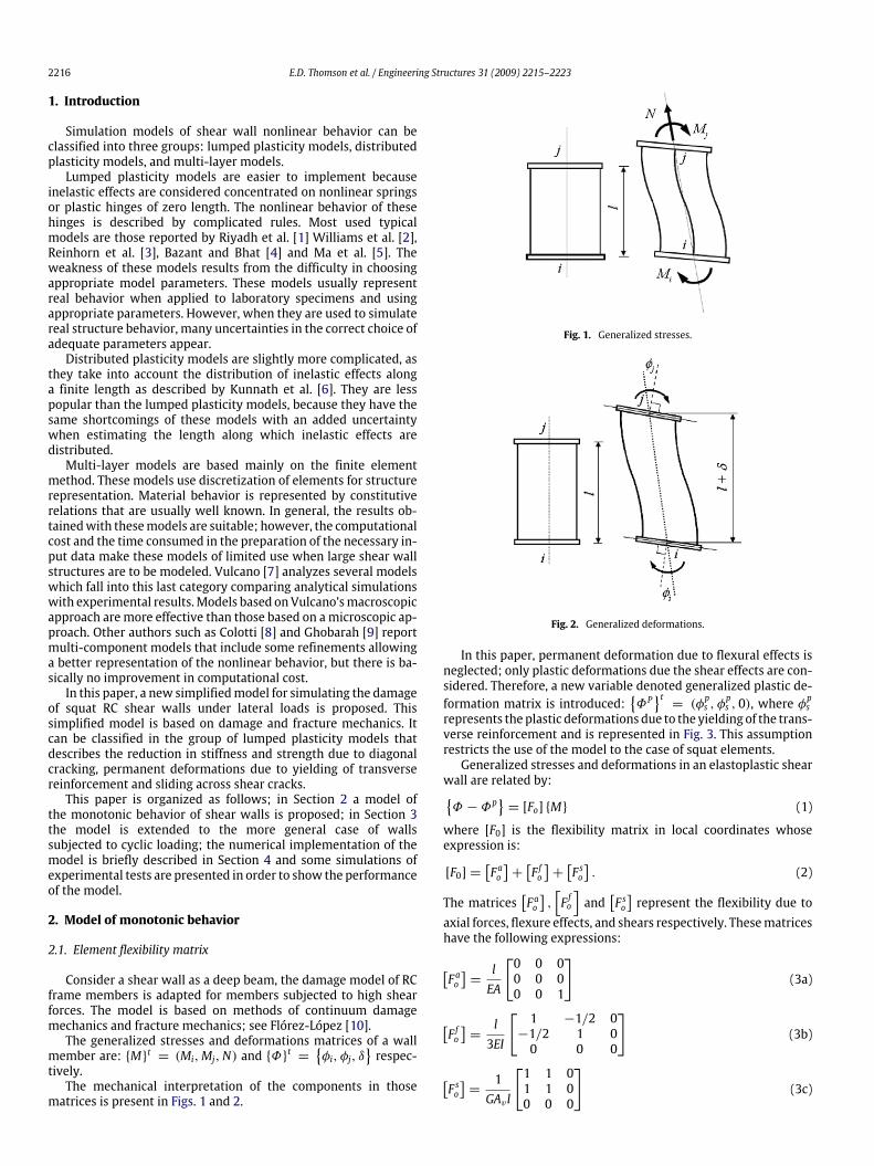
Consider a shear wall as a deep beam, the damage model of RCframe members is adapted for members subjected to high shearforces. The model is based on methods of continuum damagemechanics and fracture mechanics; see Flórez-López [10].The generalized stresses and deformations matrices of a wall
member are: {M}t = (Mi,Mj,N) and {Φ}t ={φi, φj, δ
}respec-
tively.The mechanical interpretation of the components in those
matrices is present in Figs. 1 and 2.
Fig. 1. Generalized stresses.
Fig. 2. Generalized deformations.
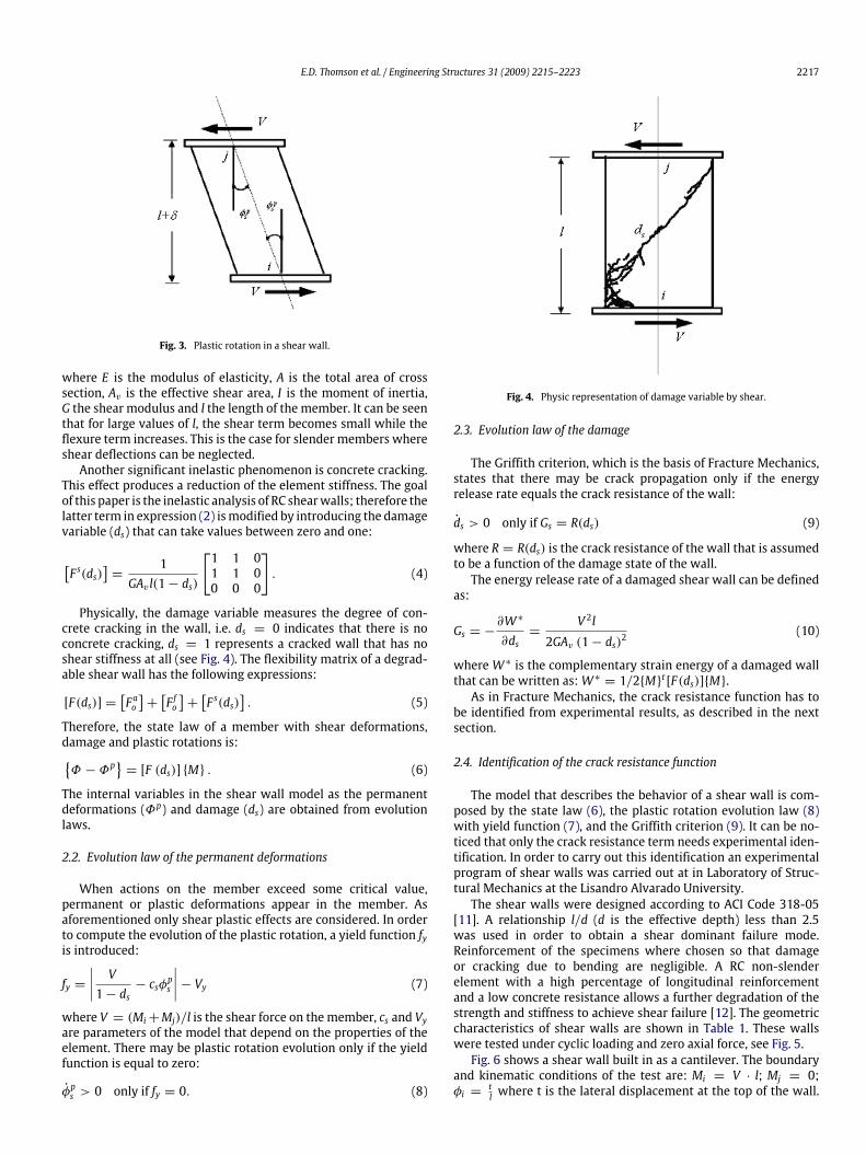
In this paper, permanent deformation due to flexural effects isneglected; only plastic deformations due the shear effects are con-sidered. Therefore, a new variable denoted generalized plastic de-formation matrix is introduced:
{ΦP}t= (φ
ps , φ
ps , 0), where φ
ps
represents the plastic deformations due to the yielding of the trans-verse reinforcement and is represented in Fig. 3. This assumptionrestricts the use of the model to the case of squat elements.Generalized stresses and deformations in an elastoplastic shear
wall are related by:{Φ − Φp
}= [Fo] {M} (1)
where [F0] is the flexibility matrix in local coordinates whoseexpression is:
[F0] =[F ao]+[F fo]+[F so]. (2)
The matrices[F ao],[F fo]and
[F so]represent the flexibility due to
axial forces, flexure effects, and shears respectively. Thesematriceshave the following expressions:
[F ao]=lEA
[0 0 00 0 00 0 1
](3a)
[F fo]=l3EI
[ 1 −1/2 0−1/2 1 00 0 0
](3b)
[F so]=
1GAv l
[1 1 01 1 00 0 0
](3c)
E.D. Thomson et al. / Engineering Structures 31 (2009) 2215–2223 2217
Fig. 3. Plastic rotation in a shear wall.
where E is the modulus of elasticity, A is the total area of crosssection, Av is the effective shear area, I is the moment of inertia,G the shear modulus and l the length of the member. It can be seenthat for large values of l, the shear term becomes small while theflexure term increases. This is the case for slender members whereshear deflections can be neglected.Another significant inelastic phenomenon is concrete cracking.
This effect produces a reduction of the element stiffness. The goalof this paper is the inelastic analysis of RC shearwalls; therefore thelatter term in expression (2) ismodified by introducing the damagevariable (ds) that can take values between zero and one:
[F s(ds)
]=
1GAv l(1− ds)
[1 1 01 1 00 0 0
]. (4)
Physically, the damage variable measures the degree of con-crete cracking in the wall, i.e. ds = 0 indicates that there is noconcrete cracking, ds = 1 represents a cracked wall that has noshear stiffness at all (see Fig. 4). The flexibility matrix of a degrad-able shear wall has the following expressions:
[F(ds)] =[F ao]+[F fo]+[F s(ds)
]. (5)
Therefore, the state law of a member with shear deformations,damage and plastic rotations is:{Φ − Φp
}= [F (ds)] {M} . (6)
The internal variables in the shear wall model as the permanentdeformations (Φp) and damage (ds) are obtained from evolutionlaws.
2.2. Evolution law of the permanent deformations
When actions on the member exceed some critical value,permanent or plastic deformations appear in the member. Asaforementioned only shear plastic effects are considered. In orderto compute the evolution of the plastic rotation, a yield function fyis introduced:
fy =∣∣∣∣ V1− ds
− csφps
∣∣∣∣− Vy (7)
where V = (Mi+Mj)/l is the shear force on the member, cs and Vyare parameters of the model that depend on the properties of theelement. There may be plastic rotation evolution only if the yieldfunction is equal to zero:
φps > 0 only if fy = 0. (8)
Fig. 4. Physic representation of damage variable by shear.
2.3. Evolution law of the damage
The Griffith criterion, which is the basis of Fracture Mechanics,states that there may be crack propagation only if the energyrelease rate equals the crack resistance of the wall:
ds > 0 only if Gs = R(ds) (9)
where R = R(ds) is the crack resistance of the wall that is assumedto be a function of the damage state of the wall.The energy release rate of a damaged shear wall can be defined
as:
Gs = −∂W ∗
∂ds=
V 2l2GAv (1− ds)2
(10)
whereW ∗ is the complementary strain energy of a damaged wallthat can be written as:W ∗ = 1/2{M}t [F(ds)]{M}.As in Fracture Mechanics, the crack resistance function has to
be identified from experimental results, as described in the nextsection.
2.4. Identification of the crack resistance function
The model that describes the behavior of a shear wall is com-posed by the state law (6), the plastic rotation evolution law (8)with yield function (7), and the Griffith criterion (9). It can be no-ticed that only the crack resistance term needs experimental iden-tification. In order to carry out this identification an experimentalprogram of shear walls was carried out at in Laboratory of Struc-tural Mechanics at the Lisandro Alvarado University.The shear walls were designed according to ACI Code 318-05
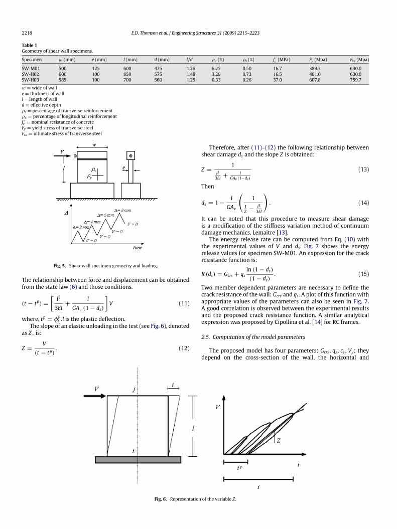
[11]. A relationship l/d (d is the effective depth) less than 2.5was used in order to obtain a shear dominant failure mode.Reinforcement of the specimens where chosen so that damageor cracking due to bending are negligible. A RC non-slenderelement with a high percentage of longitudinal reinforcementand a low concrete resistance allows a further degradation of thestrength and stiffness to achieve shear failure [12]. The geometriccharacteristics of shear walls are shown in Table 1. These wallswere tested under cyclic loading and zero axial force, see Fig. 5.Fig. 6 shows a shear wall built in as a cantilever. The boundary
and kinematic conditions of the test are: Mi = V · l; Mj = 0;φi =
tl where t is the lateral displacement at the top of the wall.
2218 E.D. Thomson et al. / Engineering Structures 31 (2009) 2215–2223
Table 1Geometry of shear wall specimens.
Specimen w (mm) e (mm) l (mm) d (mm) l/d ρv (%) ρs (%) f ′c (MPa) Fy (Mpa) Fsu (Mpa)
SW-M01 500 125 600 475 1.26 6.25 0.50 16.7 389.3 630.0SW-H02 600 100 850 575 1.48 3.29 0.73 16.5 461.0 630.0SW-H03 585 100 700 560 1.25 0.33 0.26 37.0 607.8 759.7
w =wide of walle= thickness of walll= length of walld= effective depthρs = percentage of transverse reinforcementρv = percentage of longitudinal reinforcementf ′c = nominal resistance of concreteFy = yield stress of transverse steelFsu = ultimate stress of transverse steel
Fig. 5. Shear wall specimen geometry and loading.
The relationship between force and displacement can be obtainedfrom the state law (6) and those conditions.
(t − tp) =[l3
3EI+
lGAv (1− ds)
]V (11)
where, tp = φps .l is the plastic deflection.The slope of an elastic unloading in the test (see Fig. 6), denoted
as Z, is:
Z =V
(t − tp). (12)
Therefore, after (11)–(12) the following relationship betweenshear damage ds and the slope Z is obtained:
Z =1
l33EI +
lGAv(1−ds)
(13)
Then
ds = 1−lGAv
(1
1Z −
l33EI
). (14)
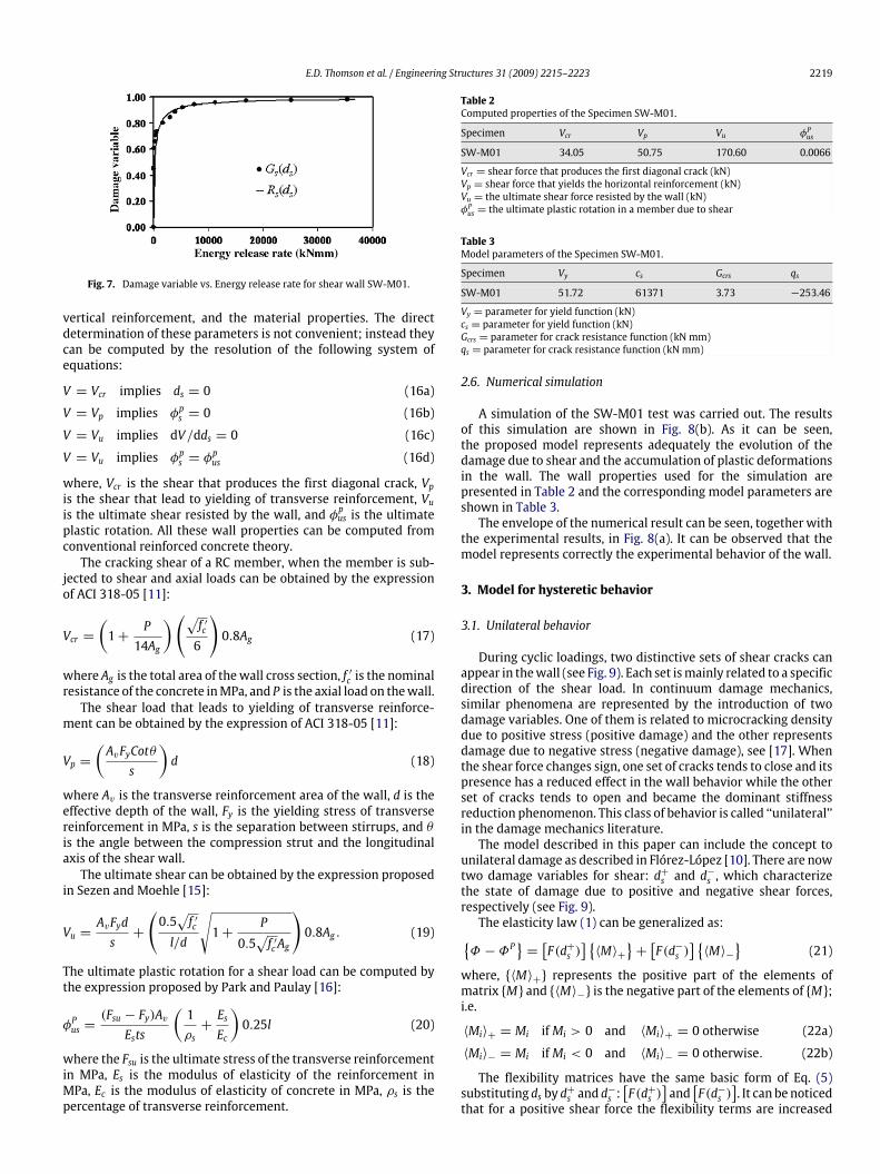
It can be noted that this procedure to measure shear damageis a modification of the stiffness variation method of continuumdamage mechanics, Lemaitre [13].The energy release rate can be computed from Eq. (10) with
the experimental values of V and ds. Fig. 7 shows the energyrelease values for specimen SW-M01. An expression for the crackresistance function is:
R (ds) = Gcrs + qsln (1− ds)(1− ds)
. (15)
Two member dependent parameters are necessary to define thecrack resistance of the wall: Gcrs and qs. A plot of this function withappropriate values of the parameters can also be seen in Fig. 7.A good correlation is observed between the experimental resultsand the proposed crack resistance function. A similar analyticalexpression was proposed by Cipollina et al. [14] for RC frames.
2.5. Computation of the model parameters
The proposed model has four parameters: Gcrs, qs, cs, Vy; theydepend on the cross-section of the wall, the horizontal and
Fig. 6. Representation of the variable Z .
E.D. Thomson et al. / Engineering Structures 31 (2009) 2215–2223 2219
Fig. 7. Damage variable vs. Energy release rate for shear wall SW-M01.
vertical reinforcement, and the material properties. The directdetermination of these parameters is not convenient; instead theycan be computed by the resolution of the following system ofequations:
V = Vcr implies ds = 0 (16a)
V = Vp implies φps = 0 (16b)
V = Vu implies dV/dds = 0 (16c)
V = Vu implies φps = φpus (16d)
where, Vcr is the shear that produces the first diagonal crack, Vpis the shear that lead to yielding of transverse reinforcement, Vuis the ultimate shear resisted by the wall, and φpus is the ultimateplastic rotation. All these wall properties can be computed fromconventional reinforced concrete theory.The cracking shear of a RC member, when the member is sub-
jected to shear and axial loads can be obtained by the expressionof ACI 318-05 [11]:
Vcr =(1+
P14Ag
)(√f ′c6
)0.8Ag (17)
where Ag is the total area of thewall cross section, f ′c is the nominalresistance of the concrete inMPa, and P is the axial load on thewall.The shear load that leads to yielding of transverse reinforce-
ment can be obtained by the expression of ACI 318-05 [11]:
Vp =(AvFyCotθs
)d (18)
where Av is the transverse reinforcement area of the wall, d is theeffective depth of the wall, Fy is the yielding stress of transversereinforcement in MPa, s is the separation between stirrups, and θis the angle between the compression strut and the longitudinalaxis of the shear wall.The ultimate shear can be obtained by the expression proposed
in Sezen and Moehle [15]:
Vu =AvFyds+
(0.5√f ′c
l/d
√1+
P
0.5√f ′cAg
)0.8Ag . (19)
The ultimate plastic rotation for a shear load can be computed bythe expression proposed by Park and Paulay [16]:
φPus =(Fsu − Fy)AvEsts
(1ρs+EsEc
)0.25l (20)
where the Fsu is the ultimate stress of the transverse reinforcementin MPa, Es is the modulus of elasticity of the reinforcement inMPa, Ec is the modulus of elasticity of concrete in MPa, ρs is thepercentage of transverse reinforcement.
Table 2Computed properties of the Specimen SW-M01.
Specimen Vcr Vp Vu φPus
SW-M01 34.05 50.75 170.60 0.0066
Vcr = shear force that produces the first diagonal crack (kN)Vp = shear force that yields the horizontal reinforcement (kN)Vu = the ultimate shear force resisted by the wall (kN)φPus = the ultimate plastic rotation in a member due to shear
Table 3Model parameters of the Specimen SW-M01.
Specimen Vy cs Gcrs qs
SW-M01 51.72 61371 3.73 −253.46
Vy = parameter for yield function (kN)cs = parameter for yield function (kN)Gcrs = parameter for crack resistance function (kN mm)qs = parameter for crack resistance function (kN mm)
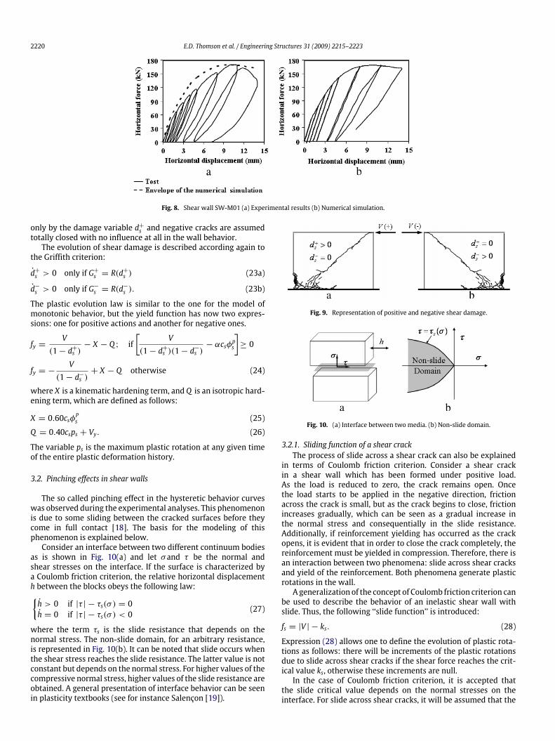
2.6. Numerical simulation
A simulation of the SW-M01 test was carried out. The resultsof this simulation are shown in Fig. 8(b). As it can be seen,the proposed model represents adequately the evolution of thedamage due to shear and the accumulation of plastic deformationsin the wall. The wall properties used for the simulation arepresented in Table 2 and the corresponding model parameters areshown in Table 3.The envelope of the numerical result can be seen, together with
the experimental results, in Fig. 8(a). It can be observed that themodel represents correctly the experimental behavior of the wall.
3. Model for hysteretic behavior
3.1. Unilateral behavior
During cyclic loadings, two distinctive sets of shear cracks canappear in thewall (see Fig. 9). Each set ismainly related to a specificdirection of the shear load. In continuum damage mechanics,similar phenomena are represented by the introduction of twodamage variables. One of them is related to microcracking densitydue to positive stress (positive damage) and the other representsdamage due to negative stress (negative damage), see [17]. Whenthe shear force changes sign, one set of cracks tends to close and itspresence has a reduced effect in the wall behavior while the otherset of cracks tends to open and became the dominant stiffnessreduction phenomenon. This class of behavior is called ‘‘unilateral’’in the damage mechanics literature.The model described in this paper can include the concept to
unilateral damage as described in Flórez-López [10]. There are nowtwo damage variables for shear: d+s and d
−s , which characterize
the state of damage due to positive and negative shear forces,respectively (see Fig. 9).The elasticity law (1) can be generalized as:{Φ − ΦP
}=[F(d+s )
] {〈M〉+
}+[F(d−s )
] {〈M〉−
}(21)
where, {〈M〉+} represents the positive part of the elements ofmatrix {M} and {〈M〉−} is the negative part of the elements of {M};i.e.
〈Mi〉+ = Mi ifMi > 0 and 〈Mi〉+ = 0 otherwise (22a)
〈Mi〉− = Mi ifMi < 0 and 〈Mi〉− = 0 otherwise. (22b)
The flexibility matrices have the same basic form of Eq. (5)substituting ds by d+s and d
−s :[F(d+s )
]and
[F(d−s )
]. It can be noticed
that for a positive shear force the flexibility terms are increased
2220 E.D. Thomson et al. / Engineering Structures 31 (2009) 2215–2223
Fig. 8. Shear wall SW-M01 (a) Experimental results (b) Numerical simulation.
only by the damage variable d+s and negative cracks are assumedtotally closed with no influence at all in the wall behavior.The evolution of shear damage is described according again to
the Griffith criterion:
d+s > 0 only if G+s = R(d+
s ) (23a)
d−s > 0 only if G−s = R(d−
s ). (23b)
The plastic evolution law is similar to the one for the model ofmonotonic behavior, but the yield function has now two expres-sions: one for positive actions and another for negative ones.
fy =V
(1− d+s )− X − Q ; if
[V
(1− d+s )(1− d−s )− αcsφps
]≥ 0
fy = −V
(1− d−s )+ X − Q otherwise (24)
where X is a kinematic hardening term, and Q is an isotropic hard-ening term, which are defined as follows:
X = 0.60csφPs (25)
Q = 0.40csps + Vy. (26)
The variable ps is the maximum plastic rotation at any given timeof the entire plastic deformation history.
3.2. Pinching effects in shear walls
The so called pinching effect in the hysteretic behavior curveswas observed during the experimental analyses. This phenomenonis due to some sliding between the cracked surfaces before theycome in full contact [18]. The basis for the modeling of thisphenomenon is explained below.Consider an interface between two different continuum bodies
as is shown in Fig. 10(a) and let σand τ be the normal andshear stresses on the interface. If the surface is characterized bya Coulomb friction criterion, the relative horizontal displacementh between the blocks obeys the following law:{h > 0 if |τ | − τs(σ ) = 0h = 0 if |τ | − τs(σ ) < 0
(27)
where the term τs is the slide resistance that depends on thenormal stress. The non-slide domain, for an arbitrary resistance,is represented in Fig. 10(b). It can be noted that slide occurs whenthe shear stress reaches the slide resistance. The latter value is notconstant but depends on the normal stress. For higher values of thecompressive normal stress, higher values of the slide resistance areobtained. A general presentation of interface behavior can be seenin plasticity textbooks (see for instance Salençon [19]).
Fig. 9. Representation of positive and negative shear damage.
Fig. 10. (a) Interface between two media. (b) Non-slide domain.
3.2.1. Sliding function of a shear crackThe process of slide across a shear crack can also be explained
in terms of Coulomb friction criterion. Consider a shear crackin a shear wall which has been formed under positive load.As the load is reduced to zero, the crack remains open. Oncethe load starts to be applied in the negative direction, frictionacross the crack is small, but as the crack begins to close, frictionincreases gradually, which can be seen as a gradual increase inthe normal stress and consequentially in the slide resistance.Additionally, if reinforcement yielding has occurred as the crackopens, it is evident that in order to close the crack completely, thereinforcement must be yielded in compression. Therefore, there isan interaction between two phenomena: slide across shear cracksand yield of the reinforcement. Both phenomena generate plasticrotations in the wall.A generalization of the concept of Coulomb friction criterion can
be used to describe the behavior of an inelastic shear wall withslide. Thus, the following ‘‘slide function’’ is introduced:
fs = |V | − ks. (28)
Expression (28) allows one to define the evolution of plastic rota-tions as follows: there will be increments of the plastic rotationsdue to slide across shear cracks if the shear force reaches the crit-ical value ks, otherwise these increments are null.In the case of Coulomb friction criterion, it is accepted that
the slide critical value depends on the normal stresses on theinterface. For slide across shear cracks, it will be assumed that the
E.D. Thomson et al. / Engineering Structures 31 (2009) 2215–2223 2221
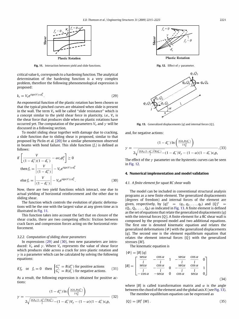
Fig. 11. Interaction between yield and slide functions.
critical value ks corresponds to a hardening function. The analyticaldetermination of the hardening function is a very complexproblem, therefore the following phenomenological expression isproposed:
ks = Voesign(V )γ φps . (29)
An exponential function of the plastic rotation has been chosen sothat the typical pinched curves are obtained when slide is presentin the wall. The term Vo will be called ‘‘slide resistance’’ which isa concept similar to the yield shear force in plasticity, i.e., Vo isthe shear force that produces slide when no plastic rotations haveoccurred yet. The computation of the parameters Vo and γ will bediscussed in a following section.To model sliding shear together with damage due to cracking,
a slide function due to sliding shear is proposed, similar to thatproposed by Picón et al. [20] for a similar phenomenon observedin beams with bond failure. This slide function (fs) is defined asfollows:
if[
V(1− d+s )(1− d−s )
− αcsφps
]≥ 0
then fs =∣∣∣∣ V(1− d+s )
∣∣∣∣− Voesign(V )γ φpselse fs =
∣∣∣∣ V(1− d−s )
∣∣∣∣− Voesign(V )γ φps . (30)
Now, there are two yield functions which interact, one due toactual yielding of horizontal reinforcement and the other due tosliding shear.The function which controls the evolution of plastic deforma-
tions will be the one with the largest value at any given time as isillustrated in Fig. 11.This function takes into account the fact that on closure of the
shear cracks, there are two competing effects: friction betweencrack faces and compression forces acting on the horizontal rein-forcement.
3.2.2. Computation of sliding shear parametersIn expressions (29) and (30), two new parameters are intro-
duced: Vo and γ . Where Vo represents the value of shear forcewhich produces slide across a crack for zero plastic rotation andγ is a parameter which can be calculated by solving the followingequations:
if fy or fs = 0 then{G+s = R(d
+
s ) for positive actionsG−s = R(d
−
s ) for negative actions.(31)
As a result, the following expression is obtained for positive ac-tions:
γ =
(1− d+s ) ln(2GAvR(d+s )l·V20
)2√2GAv(1−d+s )2R(d
+s )
l −(1− d+s )Vy − (1− α)(1− d+s )csps(32)
Fig. 12. Effect of γ parameter.
Fig. 13. Generalized displacements {q} and internal forces {Q }.
and, for negative actions:
γ =
(1− d−s ) ln(2GAvR(d−s )l·V20
)2√2GAv(1−d−s )2R(d
−s )
l −(1− d−s )Vy − (1− α)(1− d−s )csps.(33)
The effect of the γ parameter on the hysteretic curves can be seenin Fig. 12.
4. Numerical implementation and model validation
4.1. A finite element for squat RC shear walls
The model can be included in conventional structural analysisprograms as a new finite element. The generalized displacements(degrees of freedom) and internal forces of the element aregiven, respectively, by {q}t = (q1, q2, . . . , q6) and {Q }t =(Q1,Q2, . . . ,Q6) as indicated in Fig. 13. A finite element is definedas the set of equations that relate the generalizeddisplacements {q}with the internal forces {Q }. A finite element for a RC shear wall iscomposed by the proposed model and two additional equations.The first one is denoted kinematic equation and relates thegeneralized deformations {Φ} with the generalized displacements{q}. The second one is the element equilibrium equation thatrelates the element internal forces {Q } with the generalizedstresses {M}.The kinematic equation is
{Φ} = [B] {q}
[B] =
secαl
−cosαl
1 −secαl
cosαl
0
secαl
−cosαl
0 −secαl
cosαl
1− cosα −secα 0 cosα secα 0
(34)
where [B] is called transformation matrix and α is the anglebetween the chord of the element and the global axisX (see Fig. 13).The member equilibrium equation can be expressed as
{Q } = [B]t {M} . (35)
2222 E.D. Thomson et al. / Engineering Structures 31 (2009) 2215–2223
Fig. 14. Specimen SW-H02 (a) Experimental results (b) Numerical simulation.
Fig. 15. Specimen SW-H03 (a) Experimental results (b) Numerical simulation.
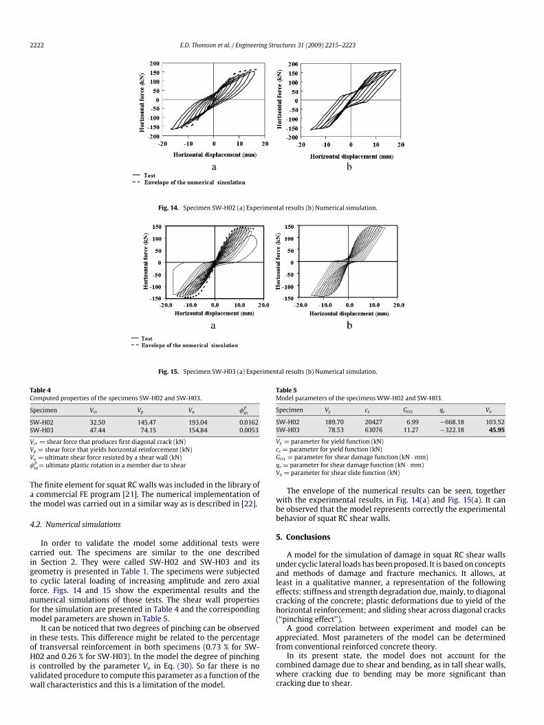
Table 4Computed properties of the specimens SW-H02 and SW-H03.
Specimen Vcr Vp Vu φPus
SW-H02 32.50 145.47 193.04 0.0162SW-H03 47.44 74.15 154.84 0.0053
Vcr = shear force that produces first diagonal crack (kN)Vp = shear force that yields horizontal reinforcement (kN)Vu = ultimate shear force resisted by a shear wall (kN)φPus= ultimate plastic rotation in a member due to shear
The finite element for squat RC walls was included in the library ofa commercial FE program [21]. The numerical implementation ofthe model was carried out in a similar way as is described in [22].
4.2. Numerical simulations
In order to validate the model some additional tests werecarried out. The specimens are similar to the one describedin Section 2. They were called SW-H02 and SW-H03 and itsgeometry is presented in Table 1. The specimens were subjectedto cyclic lateral loading of increasing amplitude and zero axialforce. Figs. 14 and 15 show the experimental results and thenumerical simulations of those tests. The shear wall propertiesfor the simulation are presented in Table 4 and the correspondingmodel parameters are shown in Table 5.It can be noticed that two degrees of pinching can be observed
in these tests. This difference might be related to the percentageof transversal reinforcement in both specimens (0.73 % for SW-H02 and 0.26 % for SW-H03). In the model the degree of pinchingis controlled by the parameter Vo in Eq. (30). So far there is novalidated procedure to compute this parameter as a function of thewall characteristics and this is a limitation of the model.
Table 5Model parameters of the specimens WW-H02 and SW-H03.
Specimen Vy cs Gcrs qs Vo
SW-H02 189.70 20427 6.99 −668.18 103.52SW-H03 78.53 63076 11.27 −322.18 45.95
Vy = parameter for yield function (kN)cs = parameter for yield function (kN)Gcrs = parameter for shear damage function (kN ·mm)qs = parameter for shear damage function (kN ·mm)Vo = parameter for shear slide function (kN)
The envelope of the numerical results can be seen, togetherwith the experimental results, in Fig. 14(a) and Fig. 15(a). It canbe observed that the model represents correctly the experimentalbehavior of squat RC shear walls.
5. Conclusions
A model for the simulation of damage in squat RC shear wallsunder cyclic lateral loads has beenproposed. It is based on conceptsand methods of damage and fracture mechanics. It allows, atleast in a qualitative manner, a representation of the followingeffects: stiffness and strength degradation due, mainly, to diagonalcracking of the concrete; plastic deformations due to yield of thehorizontal reinforcement; and sliding shear across diagonal cracks(‘‘pinching effect’’).A good correlation between experiment and model can be
appreciated. Most parameters of the model can be determinedfrom conventional reinforced concrete theory.In its present state, the model does not account for the
combined damage due to shear and bending, as in tall shear walls,where cracking due to bending may be more significant thancracking due to shear.
E.D. Thomson et al. / Engineering Structures 31 (2009) 2215–2223 2223
Acknowledgements
The experimental investigation presented in this paper wascarried out in the Laboratory of Structural Mechanics at theLisandro Alvarado University. The researchworkwas sponsored byFONACIT and CDCHT Lisandro Alvarado University, Venezuela.
Appendix. Notations
The following symbols are used in this paper:
A total cross section areaAg gross area of concrete sectionAv effective shear area of cross sectioncs parameter for yield functiond effective depthds shear damage variabled+s shear damage variable for positive actionsd−s shear damage variable for negative actionsEc modulus of elasticity of concreteE modulus of elasticityEs modulus of elasticity of steelf ′c nominal resistance of the concretefs shear slide functionFsu ultimate stress of transverse steelfy yield functionFy yield stress of transverse steel[Fo] flexibility matrix of member[F ao ] flexibility matrix due to axial forces[F fo ] flexibility matrix due to flexure effects[F so] flexibility matrix due to shear effects[F s(ds)] shear flexibility matrix of a damaged wall[F(ds)] flexibility matrix of a damaged wallG shear modulusGcrs parameter for shear damage functionGs energy release rate of damaged shear wallG+s energy release rate of a damaged shear wall for positive
actionsG−s energy release rate of a damaged shear wall for negative
actionsh relative displacement between two blocks of an interfaceks critical shear force that produces slidel length of wallMi,Mj flexural moments at nodes i and j of a member〈M〉+ positive part of the elements of matrix {M}〈M〉− negative part of the elements of matrix {M}N axial force in a memberP axial loadps maximum plastic rotation achievedqs parameter for shear damage functionQ isotropic hardening term for yield functionρs percentage of transverse reinforcementρv percentage longitudinal reinforcementR, R(ds) crack resistance functione thickness of wallV shear force in a memberVcr shear force that produces first diagonal crackVo parameter for shear slide functionVp shear force that yields horizontal reinforcementVu ultimate shear force resisted by a shear wall
Vy parameter for yield functionw wide of wallW ∗ complementary strain energy of a damaged wallX kinematic hardening term for yield functionZ slope of elastic unloadingα parameter of yield functionδ axial elongation of the member cordt horizontal displacement at top of shear walltp plastic horizontal displacement at top of wallφi, φj total rotation at nodes i and j of memberφPs plastic rotation in a member due to shearφPus ultimate plastic rotation in a member due to shearγ parameter for shear slide functionσ normal stress across an interfaceτ shear stress across an interfaceτs shear slide resistance
References
[1] Riyadh H, Mohamad M, Murat D. Prediction of damage in R/C shear panelssubjected to reversed cyclic loading. J Earth Eng 2005;9(1):41–66.
[2] Williams MS, Villernure I, Sexsmith RG. Evaluation of seismic damage indicesfor concrete elements loaded in combined shear and flexure. ACI Struct J 1997;94(3):315–22.
[3] Reinhorn AM, Kunnath SK, Mander JB. In: Fafjar P, Krawinkler yH, editors.Seismic design of structures for damage control in nonlinear seismic analysisand design of reinforced concrete buildings. London: Elsevier Applied Science;1992. p. 63–76.
[4] Bazant ZD, Bhat PD. Prediction of hysteresis of reinforced concrete members.J Struct Eng, ASCE 1977;103(1):153–80.
[5] Ma SM, Bertero VV, Popov EP. Experimental and analytical studies on thehysteretic behavior of reinforced concrete rectangular and T -beams. ReportNo. EERC 76-2, Berkeley: Earthquake Engineering Research Center, Universityof California, 1976.
[6] Kunnath SK, Reinhorn A, Park YJ. Analytical modeling of inelastic seismicresponse of R/C structures. J Struct Eng, ASCE 1990;116(4):996–1017.
[7] Vulcano A. In: Fafjar P, Krawinkler yH, editors. Macroscopic modeling fornonlinear analysis of rc structural walls in nonlinear seismic analysis anddesign of reinforced concrete buildings. London: Elsevier Applied Science;1992. p. 81–202.
[8] Colotti V. Shear behavior of RC structuralwalls. J Struct Eng, ASCE 1993;119(3):728–46.
[9] Ghobarah A, Youssef M. Modelling of reinforced concrete structural walls. EngStruct, Elsevier Science 1999;21(10):912–23.
[10] Flórez-López J. Simplified model of unilateral damage for RC frames. J StructEng, ASCE 1995;121(12):1765–72.
[11] American Concrete Institute (ACI). Building code requirement for structuralconcrete. ACI Committee 318, Farmington Hills, Mich, 2005.
[12] Woodward KA, Jirsa JO. Influence of reinforcement on RC short columnsresistance. J Struct Eng, ASCE 1984;110(1):90–104.
[13] Lemaitre J. A course on damage mechanics. Germany: Springer-Verlag; 1992.[14] Cipollina A, López-Inojosa A, Flórez-López J. A simplified damage mechanics
approach to nonlinear analysis of frames. Comput Struct 1995;54(6):1113–26.[15] Sezen H, Moehle J. Shear strength model for lightly reinforced concrete
columns. J Struct Eng, ASCE 2004;130(11):1692–703.[16] Park R, Paulay T. Reinforced concrete structures. New York: John Wiley and
Sons; 1975.[17] Ladeveze P. On an anisotropic damage theory. In: Proc. of the CNRS
international colloquium of failure criteria of structural media. France: Villardde Lans; 1983.
[18] Saatcioglu M, Humar JM. Dynamic analysis of buildings for earthquake-resistant design. J Civ Eng Can 2003;30:338–59.
[19] Salençon J. Calcul à la rupture et analyse limite. Presses de l’école nationale desponts et chaussées, Paris, France, 1983.
[20] Picón-Rodríguez R, Quintero-Febres C, Flórez-López J. Modeling of cyclic bonddeterioration in RC beam-column connections. Struct Eng Mech 2007;26(5):569–89.
[21] Abaqus user’s manual – Version 6.2. Pawtucket, RI: Hibbitt, Karlson &Sorensen, Inc; 2001.
[22] MaranteME, Flórez-López J. Three dimensional analysis of reinforced concreteframes based on lumped damage mechanics. Int J Solids and Struct 2003;40(19):5109–23.