Embed Size (px)
Citation preview

Revision 2.05B
MCS-Magnum Controller SystemSimplified Description and Troubleshooting
Plus MCS-MAGNUM Alarms and Safeties
Revision 2017-11-07

2
The MCS Commitment
Our commitment is to provide practical solutions for the industry’s needs and to be both a leader and a partner in the effective use of microprocessor controls.
Micro Control Systems, Inc.5580 Enterprise ParkwayFort Myers, Florida 33905
USAPhone: (239) 694-0089
Fax: (239) 694-0031www.mcscontrols.com
Information contained in this manual has been prepared by Micro Control Systems, Inc. and is company confidential and copyright © protected 2017.
Copying or distributing this document is prohibited unless expressly approved by MCS.

3
Table of ContentMCS-MAGNUM CONTROLLER TROUBLESHOOTING
1.1. Troubleshooting General Dead Board Symptoms.........................................................................................................................................................61.2. Troubleshooting Sensor Input Problems .......................................................................................................................................................................71.3. Troubleshooting Relay Output Problems ......................................................................................................................................................................8
Appendix A1.4. Entering Authorization Codes to Log In and Out of a Magnum .....................................................................................................................................9
Appendix A (continued)1.5. Entering Authorization Codes to Log In and Out of a Magnum ...................................................................................................................................10
Appendix B1.1. Manually Turning On and Off a Magnum Relay Output ..............................................................................................................................................11
Appendix B (continued)1.2. Manually Turning On and Off a Magnum Relay Output ..............................................................................................................................................12
Appendix C1.1. Determining and Changing the Network Address of a Magnum .................................................................................................................................13
Appendix C (continued)1.2. Determining and Changing the Network Address of a Magnum .................................................................................................................................14
Appendix D1.1. Sensor Input Reference Table .....................................................................................................................................................................................15
Appendix D (continued)1.2. Sensor Input Reference Table .....................................................................................................................................................................................16
Appendix E1.1. Analog Sensor Input Reference Table ........................................................................................................................................................................17
Appendix F1.1. MCS-UPC Status LED Code Descriptions ..................................................................................................................................................................18
Magnum Alarms and Safeties1.1. There are four types of alarms that are generated by the Magnum control logic: .......................................................................................................191.2. Information Only Alarms ..............................................................................................................................................................................................19
1.2.1 System Generated Alarms .................................................................................................................................................................................191.2.2 User Initiated Alarms ..........................................................................................................................................................................................201.2.3 Automatic Alarms ...............................................................................................................................................................................................20
1.3. Magnum System Alarms .............................................................................................................................................................................................201.3.1 Configuration Alarms .........................................................................................................................................................................................201.3.2 MCS Local Network Alarms ...............................................................................................................................................................................211.3.3 Key Sensors Alarms ..........................................................................................................................................................................................211.3.4 Emergency Stop Alarm ......................................................................................................................................................................................21
1.4. Setpoint safety alarms .................................................................................................................................................................................................211.4.1 Sensor Inputs Used With Magnum Setpoint Safeties: .......................................................................................................................................221.4.2 Setpoint safeties ................................................................................................................................................................................................22
1.5. TurboCor Compressor Alarms .....................................................................................................................................................................................24

4
MCS-MAGNUM CONTROLLER TROUBLESHOOTING

5
Measure voltage at acinput connector block andverify that it is within 10percent of rated voltage
Troubleshooting General DeadBoard Symptoms
Voltageok?
Ac inputfuse blown?
Replace fuse. Iffuse blows again
replace board
Correct ac supplyto board
Start
Press RESETbutton on board
Is red RESETlight on all the
time?
Is green16VDC light
on?
Magnum Micro Controller Systems
If board has avoltage selectorswitch, is it set
correctly?
Turn power off, setswitch to correct
voltage, turn power on
Turn power off, wait10 seconds, turnpower back on
Board was locked updue to momentarypower dip or spike
Problemsolved?
Board was locked updue to momentarypower dip or spike
Replace board
Is board aMagnum?
Problemsolved?
Press RESETbutton on board
Turn power off, wait10 seconds, turnpower back on
Board was locked updue to momentarypower dip or spike
Problemsolved?
Board was locked updue to momentarypower dip or spike
Problemsolved? Replace board
Replace board
Is LCDbacklight on?
Try to reloadsoftware
Problemsolved?
Replace board
Software wascorrupted
YesYes
Yes
Yes Yes
Yes
Yes
Yes
Yes Yes
Yes
Replace board
Yes
No
No
No
NoNo
No
NoNo
No
No
No
1.1. Troubleshooting General Dead Board Symptoms

6
Start
Are ALL sensorson the board not
responding?
Go to any sensor inputon the board and
measure dc voltagefrom +5 pin to ground
4.75 to 5.25volts dc?
Yes
Remove all sensor blocksfrom board, wait 10 seconds,
then measure dc voltagefrom +5 pin of any sensorinput on board to ground
No
4.75 to 5.25volts dc?
Turn power off to boardand measure for short
from +5 pin of any sensorinput on board to ground
No
Shorted?
Replace board
No
Board is defect and mayhave been damaged byovervoltage applied to a
sensor input
Replace board
Yes
Go to defect sensor inputand remove connector
block
üücorrectly?
No
Defect sensor orwiring to sensor
Yes
Yes
YesBoard is defect and mayhave been damaged byovervoltage applied to
the sensor input
If system uses expansion boards,verify MCS-I/O communication byseeing if red TX light blinks on allboards and also check for proper
address jumper settings on allexpansion boards
Check that all sensor inputAnalog / Digital jumpersare set correctly and all
sensors are set to AUTO
No
If ANALOG sensor, connectMCS-SENSOR-TEST block (100K ohm1/4 watt resistor from +5 pin to SI pin onconnector base) and compare sensor
reading to Appendix J
If DIGITAL sensor,connect jumper wire from
+5 pin to SI pin onconnector base and see ifsensor reading changes
from ON to OFF or OFF toON
Troubleshooting SensorInput Problems
Magnum Micro Controller Systems
Reconnect Sensor 1 andmeasure dc voltage from
+5 pin of any sensorinput on board to ground
4.75 to 5.25volts dc?
The sensor or wiring tosensor you just
reconnected is shortedto ground
Reconnect the next sensorand measure dc voltage
from +5 pin of any sensorinput on board to ground
Yes
No
1.2. Troubleshooting Sensor Input Problems

7
Start
Are ALL relayson the board not
responding?
Turn power off,wait 10 seconds,
turn power back on
All relayswork now?
YesReplace board
Go to defect relayoutput, remove
connector block and setrelay to MANOFF
At the connector baseis there less than 1ohm of resistancebeween COM and
NC?
No
Set relay toMANON
Yes
If system uses expansion boards,verify MCS-I/O communication byseeing if red TX light blinks on allboards and also check for proper
address jumper settings on allexpansion boards
Check that all relaysare set to AUTO
(See Appendix H)
No
No
Board was locked updue to momentarypower dip or spike
Yes
Is the relayoutput fuse
blown?Replace board
No
Replace fuse and set relay toAUTO If fuse blows again afterputting system back into normal
operation, problem is due todefect outbound control device
or a short in the wiring.
Yes
At the connector baseis there less than 1ohm of resistancebetween COM and
NO?
Replace boardNo
Board is ok. Set relay to AUTO andcheck wiring from relay output
connector block to outbound controlleddevice. Also, if board is a MCS-I/O orRO8 refer to Appendix K for possiblesnubber network leakage issues and
how to overcome them.
Yes
Troubleshooting RelayOutput Problems
Magnum Micro Controller Systems
1.3. Troubleshooting Relay Output Problems

8
1.4. Troubleshooting Lost I/O Communication Problems
9
Start
Is TX I/O lighton the Magnum
blinking?
Locate expansionboard where TX
LED is not blinking
Does boardhave power?
Replace fuse. If fuseblows again, replace
expansion board
Ac inputfuse blown?
No
Yes
Replace expansionboard
Yes
Check wiring to acinput block
No
No
Verify that MCS I/Otermination jumper ison first and last board
only
On Magnum board,turn power off, swapchips U12 and U13,turn power back on
No
Yes
Does TX light onat least ONE
expansion boardblink?
Yes
YesOn Magnum board,turn power off, swapchips U12 and U13,turn power back on
Does TX light on atleast ONE
expansion boardblink?
No
Chip that was inU12 is defect
Yes
Replace Magnumboard
No
Verify that addressjumpers on all
expansion boards areset correctly
Turn poweroff to
Magnum for10 seconds,turn power
back on
Does TX I/O lighton the Magnum
blink now?
Magnum was lockedup due to momentary
power dip or spike
Troubleshooting Lost I/OCommunication Problems
Magnum Micro Controller Systems
Replace Magnumboard
No
Yes
Does TX I/O lighton the Magnum
blink now?
Chip that was inU12 is defective
Verify that MCS I/Owiring between boardsis correct, especially
polarity
9
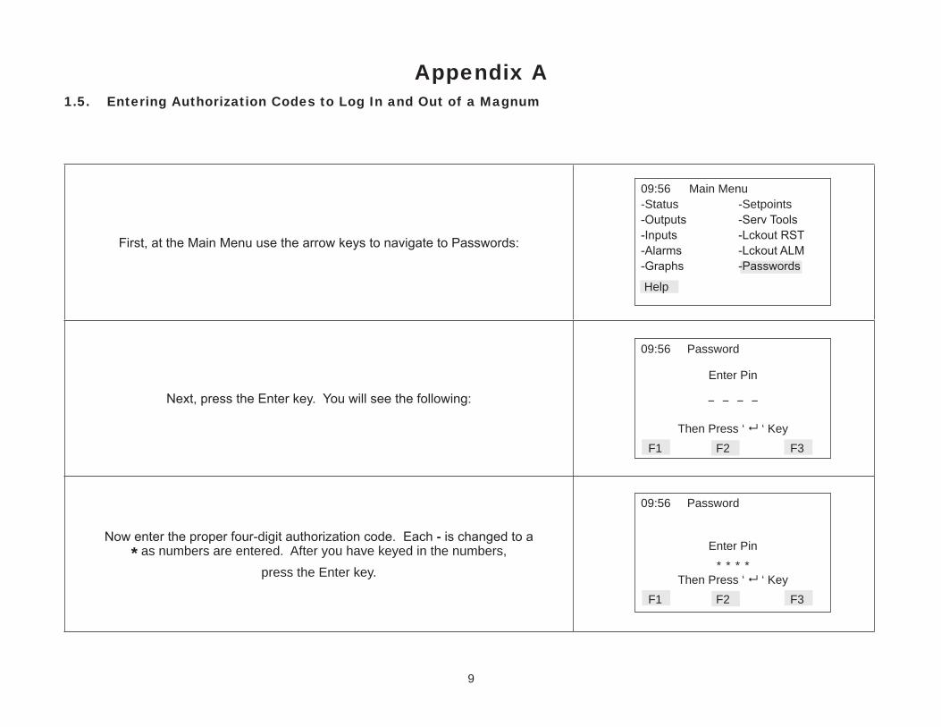
Appendix A1.5. Entering Authorization Codes to Log In and Out of a Magnum
First, at the Main Menu use the arrow keys to navigate to Passwords:
Next, press the Enter key. You will see the following:
Now enter the proper four-digit authorization code. Each - is changed to a* as numbers are entered. After you have keyed in the numbers,
press the Enter key.
09:56 Main Menu-Status -Setpoints-Outputs -Serv Tools-Inputs -Lckout RST-Alarms -Lckout ALM-Graphs -Passwords
Help
09:56 Password
Enter Pin
- - - -
Then Press ‘ ‘ Key F1 F2 F3
09:56 Password
Enter Pin* * * *
Then Press ‘ ‘ Key F1 F2 F3

10
Appendix A (continued)1.6. Entering Authorization Codes to Log In and Out of a Magnum
The Magnum will tell you if it accepted your code and the level of authorization. For example,
if you entered a valid factory authorization code you will see the following:
If you entered an invalid authorization code you will see the following:
Once you are logged in you can log out immediately by simply entering any invalid authorization code. If you are logged in and no keys are pressed for more than 15
minutes the Magnum will automatically log you out, warning you shortly before with how many seconds remaining as shown here:
09:56 Password
Level – VIEW ONLYInvalid
Pin Then Press ‘ ‘ Key
F1 F2 F3
Press Any Keyto Avoid
Auth Log Out 60
09:56 Password
Level – Factory
Then Press ‘ ‘ Key
F1 F2 F3
11
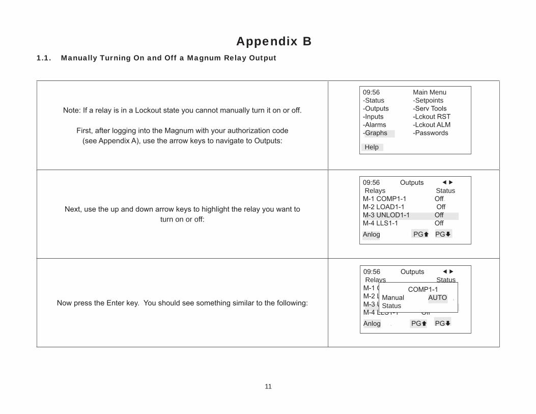
Appendix B1.1. Manually Turning On and Off a Magnum Relay Output
Note: If a relay is in a Lockout state you cannot manually turn it on or off.
First, after logging into the Magnum with your authorization code (see Appendix A), use the arrow keys to navigate to Outputs:
Next, use the up and down arrow keys to highlight the relay you want to turn on or off:
Now press the Enter key. You should see something similar to the following:
09:56 Main Menu-Status -Setpoints-Outputs -Serv Tools-Inputs -Lckout RST-Alarms -Lckout ALM-Graphs -Passwords
Help
09:56 Outputs Relays StatusM-1 COMP1-1 Off. M-2 LOAD1-1 OffM-3 UNLOD1-1 OffM-4 LLS1-1 Off Anlog .PG PG
09:56 Outputs Relays StatusM-1 COMP1-1 Off. M-2 LOAD1-1 OffM-3 UNLOD1-1 OffM-4 LLS1-1 Off Anlog . PG PG
COMP1-1Manual AUTO ,Status

12
Appendix B (continued)1.2. Manually Turning On and Off a Magnum Relay Output
Use the up and down arrow keys to cycle through the three modes for the relay output: AUTO, MANON or MANOFF
Stop when you reach the one you want:
Finally, press the Enter key to make the change. In our example the relay output is now manually turned on as shown here:
Remember to return the relay output to AUTO mode when you are done!
09:56 Outputs Relays StatusM-1 COMP1-1 Off. M-2 LOAD1-1 OffM-3 UNLOD1-1 OffM-4 LLS1-1 Off Anlog PG PG
Change Made
09:56 Outputs Relays StatusM-1 COMP1-1 Off. M-2 LOAD1-1 OffM-3 UNLOD1-1 OffM-4 LLS1-1 Off Anlog PG PG
COMP1-1Manual MANONStatus

13
Appendix C1.1. Determining and Changing the Network Address of a Magnum
First, at the Main Menu use the arrow keys to navigate to Serv Tools:
Next, press the Enter key. You will see the following:
Use the up and down arrow keys to highlight Address:
09:56 Main Menu-Status -Setpoints-Outputs -Serv Tools-Inputs -Lckout RST-Alarms -Lckout ALM-Graphs -Passwords
Help
09:56 Serv Tools-RS-485 Network 1. -Ethernet Network-System Info-Time / Date-Display PG PG
09:56 RS-485 SetupProtocol MCSAddress 1 .Baud Rate 19200
Back,

14
Appendix C (continued)1.2. Determining and Changing the Network Address of a Magnum
Now press the Enter key. You should see something similar to the following:
Use the up and down arrow keys to select the Address number:
Finally, press the Enter key to make the change. In our example the RS-485 network address has been changed from 1 to 2:
09:56 RS-485 SetupProtocol MCSAddress 1 .Baud Rate 19200
Back,
Address 1
09:56 RS-485 SetupProtocol MCS Address 1 .Baud R 00
Back,
Address 2
09:56 RS-485 SetupProtocol MCSAddress 2 .Baud Rate 19200
Back,
Changes Made

15
To troubleshoot analog sensor input problems and determine where the problem is, simply remove the sensor input connector block of the input you want to test and plug in a MCS-SENSOR-TEST block. If you do not have a MCS-SENSOR-TEST block you can connect a 100K ohm 1% ¼ watt resistor between the +5 and S1 pins of the suspect sensor input on the board with the original sensor connector block removed.
After you have done this, compare the reading displayed by the Magnum with the table of the most common sensor types on the right. If the reading is close to what is found in the table for that particular sensor type you can safely assume that the board is functioning normally and that the problem lies with the sensor itself of the wiring from the sensor to the board.
Appendix D1.1. Sensor Input Reference Table
Sensor Type Reading600VAC4 337.8V
A FLW % -99.9%
A100x2 -99.9A
A250x2 -99.9A
AIR AVG -99.9A
AKS31R5 -98.8P
AKS32-2 71.6P
AKS32-5 179.0P
AMPS100 -99.9A
AMPS250 -99.9A
ATPE500 999.9F
CARR-5K* 77.0F
CDUCT'Y 499u
CFM .25 -999c
CFM 1in -999c
C-I AMB -99.9F
C-I FLW -999
C-I IN -99.9F
Sensor Type ReadingC-I OUT -99.9F
CT-100 57.0A
CT10010 5.6A
CT10017 99.3A
CT100d2 28.5A
CT100d3 19.0A
CT100d5 76.7F
CT100d7 -99.9A
CT100x2 115.0A
CT10d25 2.1A
CT-1500* 865.0A
CT-250 143.5A
CT25017 248.6A
CT250x2 287.6A
CT300 149.7A
CT300d10 15.0A
CT300d2 75.4A
CT300d5 30.1A
Sensor Type ReadingCT300x17 256.5A
CT300x2 287.0A
CT500 287.6A
CT50017 498.2A
CT50035 931.0A
CT500x2 575.3A
CT750 429.4A
CT800 448.0A
DEC1NOCH -99.9
DEC2NOCH -9.99
DEMAND%* 87.5%
DIFF100 -99.9P
ECLIP-1 -99.9P
ECLIP-2 100.0P
ECLIP-5 250.2O
HB350 174.9P
HB700 350.0P
HUMD 54.0%

16
Appendix D (continued)1.2. Sensor Input Reference Table
Sensor Type ReadingHUMD2 54.0%
LD1000 500p
M 50-KW 43.6K
M 75-KW 65.1K
M100-KW 86.6K
MCS 667 100.0P
MCS CO2 1001p
MCS-200 100.0P
MCS-500 100.0P
MCST100 77.0F
MCSX400 99.9P
MCSX500 99.9P
MEDIA-5 -99.9P
METER P -999p
PT 1000* 169.0F
PT100 213.1F
R22 PPM 500p
REF LVL 50%
ROSE300 113.0P
ROSE500 188.6P
RPM'S -999R
S FLW T -999%
S TMP T -999F
SAFMAG -99.9G
Sensor Type ReadingSTAEFA -99.9”
STAT 50 23.5”
STAT CO2 -999p
STAT.25 -9.99”
STAT0.2 0.07”
STAT1 % 1233.6%
STAT1 F 1233.6%
STAT2 % 4.8%
STAT2 F -99.9F
STAT3 % -99.9%
STAT3 F -99.9F
STAT4 % -99.9%
STAT4 F -99.9F
STATIC.2ib 0.10”
STATIC1 -99.9”
STATIC3 -99.9”
STATIC5 1.8”
STATIC5iB 2.50”
T100LOW .999p
TI-150 60.3P
TI-150A 75.0P
TI-2ACE 110.2A
TIACE17 190.8A
TONS 1DEC -99.9T
Sensor Type ReadingVAC-600 326.6V

17
Magnum Alarms and Safeties1.1. There are four types of alarms that are generated by the Magnum control logic:
� Information only alarms, � Magnum system alarms and � Chiller Setpoint safety alarms � TurboCor Compressor Alarms
All alarms have the same format. The alarm is identified and is date/time stamped. Alarms can be viewed from the Magnum keypad by selecting the ‘Alarms’ from the main menu, or through MCS-Connect.
1.2. Information Only Alarms1.2.1 System Generated AlarmsThe following alarms are generated to provide information; they will not cause a change in the control algorithm such as a lock out condition or a Relay Output being forced off.
� POWER FAILED – Generated when power to the Magnum was lost. � POWER RETURNED – Generated when power to the Magnum returned. � HW DATE INVALID – The date contained/read from the hardware real time clock chip is not valid. Check battery voltage, it should be
> 2.0 vdc. � HW TIME INVALID – The time contained/read from the hardware real time clock chip is not valid. Check battery voltage, it should be
> 2.0 vdc. � SW DATE INVALID – The date contained/read from the software clock is not valid. � SW TIME INVALID - The time contained/read from the software clock is not valid. � RAM INTEGRITY – the data contained in the battery-backed up RAM memory may be corrupted. This does not stop the Magnum
from running. It means the historical data may be incorrect (run times, cycles, min/max values, and trend/graph data). � WATCHDOG RESET – The Magnum has reset itself because of improper operator of the Magnum board. Please consult the manu-
facturer if this alarm has occurred. � LOST A/D CONVTR – The Magnum microprocessor has lost communications to the Analog to Digital converter chip (chip that con-
verts sensor voltages to a digital number). Check for a shorted sensor that may cause � LOST DISPLAY – Generated when communication to the Keypad/Display is lost. � CF INIT ERROR – The Compact Flash card that was installed cannot be initialized and therefore cannot be used. Replace the Com-
pact Flash card with one that works. � BATTERY FAILED – Generated when Magnum is not getting power from the Battery.

18
1.2.2 User Initiated AlarmsThe following alarms indicate that an individual took action: (Most require proper authorization)
� LOCKOUT RESET – Generated when a user resets a compressor other unit from a locked condition. � COMPUTER RESET – Generated when the manual reset button on the Magnum is pressed. � ALARMS CLEARED – Generated when a user clears the alarm history. � STPT CHANGED – Generated when a user makes a change to a Setpoint; the number of the Setpoint will also be displayed with the
alarm. � RO TO (Selected Condition) – Generated when a user manually changes the condition of a Relay Output (either AUTO, MANON, or
MANOFF). � AO TO (Selected Condition) – Generated when a user changes the condition of an Analog Output (either AUTO or MANUAL. If
MANUAL, then a dialog box will appear to input the number value). � SI TO (Selected Condition) – Generated when a user changes the condition of a Sensor Input (If a digital input, then either AUTO,
MANON, or MANOFF. If an analog input, then either AUTO or MANUAL. If MANUAL, then a dialog box will appear to input the number value).
� POINT INFO CLEAR – Generated when a user clears all point information (run times, cycles, min/max values, etc.). � CLOCK SET – Generated when a user makes a change to the Magnum real time clock. � CFG DOWNLOADED – Generated when a user uploads a new configuration file into the Magnum. � ETHERNET CHANGE – Generated when a user makes a change to the Ethernet settings through the Keypad/Display. � RS485 CHANGED – Generated when a user makes changes to the RS485 address through the Keypad/Display. � CF CARD INSERTED – Generated when a user inserts a Compact Flash memory card into the Magnum. � CF CARD REMOVED – Generated when a user removes a Compact Flash memory card from the Magnum.
1.2.3 Automatic AlarmsThe following alarms indicate an action that the Magnum made automatically:
� ROTATED LEAD – Generated when the Magnum automatically rotates the Lead Compressor. � DAYLIGHT SAVINGS – Generated when the Magnum automatically changes the real time clock to adjust for Daylight Savings Time.
1.3. Magnum System Alarms1.3.1 Configuration AlarmsThese alarms indicate a problem with the configuration file in the system. The system is not operational and a new configuration must be transmit-ted to the unit through MCS-Connect.
� INVALID CONFIG – Checksums are incorrect.

19
� INVALID CFG VER – The version number of the configuration is invalid. � INVALID CFG TYPE – The configuration type does not match the software type.
1.3.2 MCS Local Network AlarmsThese alarms indicate problems with the MCS local network:
� LOST SI COMM #_ / LOST RO COMM #_–Generated when communications to a Sensor Input or Relay Output board is lost. The number of the board will be displayed with the alarm. The system can be accessed but will be in a NO RUN- I/O LOST state.
� MCS-STAT OFFLINE – The Magnum has lost communications to the MCS-STAT. � LOST IO SHUTDOWN – Generated when Magnum is running and there are no communications to one or more of the I/O boards. The
system can be accessed but will be in a NO RUN- I/O LOST state. � LOST I/O RESTART – Generated when the Magnum does an automatic reset once I/O communications are restored.
1.3.3 Key Sensors AlarmsThese alarms indicate a problem with a key sensor, it is either shorted or open. The alarm will contain ALARM followed by the 10-character name of the sensor. The following sensors related to the entire system are tested:
� Leaving temperature: If failed, then Lock Out the system. � Returning temperature: If failed, then alarm only no Lock Out. � Ambient temperature: If failed, then alarm only no Lock Out.
The following compressor sensors are tested. If they fail, then that compressor only is locked out: � Suction pressure and temperature � Discharge pressure and temperature � Oil pressure and temperature � Motor temperature (if an analog input)
1.3.4 Emergency Stop Alarm � EMERGENCY STOP – Generated when the emergency stop switch has been turned on. The system can be accessed but is in a Lock
Out state.
1.4. Setpoint safety alarmsThe Magnum algorithm incorporates a number of safety checks, based on Setpoints, preventing unsafe conditions that could potentially cause damage to the system. When a safety trips the circuit will be in a SAFETY TRIPPED state. The circuit will remain in this state for the time in the ‘Safety Down Time (min)’ cell and then move to the CMP ANTICYCLE or CMP IS OFF state where the compressor will be allowed to run again if required. If the same safety trip occurs again within the time in the ‘Lockout Delay Hrs’ cell since the first trip, the circuit will be set to CMP LOCKED OUT state, which requires a manual reset to restart the compressor. If the lockout delay time is set to zero, the Magnum will generate a lockout condition the first time that the safety occurs.

20
1.4.1 Sensor Inputs Used With Magnum Setpoint Safeties: � Suction Pressure(Analog or Digital) � Discharge Pressure (Analog or Digital) � Oil Pressure (Analog or Digital) � Oil Differential Pressure (Calculated value) � Oil Temperature (Analog or Digital) � Discharge Temperature (Analog or Digital) � Motor Temperature (Analog or Digital) � Motor Amps (Analog or Digital) � Motor Fault (Analog or Digital) � Liquid Temperature (Analog Only) � Compress Proof (Digital Only) � Flow Switch (Digital Only)
1.4.2 Setpoint safetiesFor a safety trip to occur, both the Sensor Input and the associated Setpoint must be active. If a safety trips, the alarm name will consist of the Setpoint name plus additional identification such as point number, compressor number, or 30 second history leading up to the trip if applicable.Note: Most safeties are checked only if the compressor is running, however if the safety is always checked it will be noted.The following is a list of safeties that are incorporated in the standard chiller algorithm control. These safeties are checked every second. For a system with multiple circuits, each one is tested individually. If a safety trip occurs, only that respective compressor will be affected, the others will continue to function normally.
Freeze Protection (SAFETY IS ALWAYS CHECKED)If the leaving temperature drops below the Setpoint value then the entire system will Lock Out and a FREEZE alarm will be generated. There is also an option to have one freeze protect for each individual circuit. Refer to section 11 Setpoint #111.
No Flow ProtectionIf a flow switch is used, then the entire system will be Locked Out if Setpoint #105 is active. If the Setpoint is inactive, the Magnum will determine if there is a second pump, if so it will be started. Else, the system will shut down and automatically restart when the flow switch is on, indicating flow has returned. There is also an option to have a flow switch for each individual circuit. Refer to section 11 Setpoint #105.
Phase Loss ProtectionPhase loss, as indicated by the phase loss monitor, will result in the entire system being Locked Off and a phase loss alarm will be generated. If Setpoint #166 is inactive the Magnum will wait for 2 seconds before the Lock Out occurs. The alarm will be PHASE LOSS and no restart will be attempted. If Setpoint #166 is active, the name of the Setpoint will be in the message. Refer to section 11 Setpoint #166.

21
Low Differential Oil PressureThis safety is designed to meet the compressor manufacturer requirements on oil pressure. For the first 5 seconds following a compressor start (60 seconds if Hitachi screw compressor) this safety is NOT checked. For the next 30 seconds, if the oil differential pressure drops below ½ of the value of the Setpoint or the digital input turns ON for the time specified in the ‘Time (sec)’ field of that Setpoint, then the circuit will be Locked Out and a LOW OIL alarm generated. After this time period, if the oil differential pressure drops below the value of the Setpoint and it remains there for the time specified in the ‘Time (sec)’ field, then the compressor will be Locked Out and a low oil alarm generated. This safety is checked for when the compressor is on and not in a Pump Down state. Refer to section 11 Setpoint #91.
Low Suction PressureIf the suction pressure drops below the value of the Setpoint or the digital input turns ON for the time specified in the ‘Time (sec)’ field, the com-pressor will be locked out and a LOW SUCTION alarm generated. This safety is bypassed when the compressor is in a Pump Down state. This safety can also be used as a freeze protection based upon the suction pressure. When this safety trip occurs, all compressors in the same suction group will react in the same manner. Refer to section 11 Setpoint #77.
Unsafe Suction PressureThis safety is similar to the low suction pressure safety, except it is often set up with a lower value and a shorter safety time. If the suction pressure drops below the value of the Setpoint or the digital input turns ON for the time specified in the ‘Time (sec)’ field of that Setpoint, then the circuit will be Locked Out and a UNSAFE SUCTION alarm generated. This safety will always cause a Lock Out on the first trip, requiring a manual reset. This safety is bypassed when the compressor is in a Pump Down state. When this safety trip occurs, all compressors in the same suction group will react the same. Refer to section 11 Setpoint #80.
High Discharge Pressure (SAFETY IS ALWAYS CHECKED)If the discharge pressure rises above the value of the Setpoint or the digital input turns ON for the time specified in the ‘Time (sec)’ field of that Setpoint, then the circuit will be locked out and a HIGH DISCHARGE alarm generated. Refer to section 11 Setpoint #81.
Low Discharge PressureIf the discharge pressure drops below the value of the Setpoint for the time specified in the ‘Time (sec)’ field, the compressor will be Locked Out and a LOW DISCHARGE alarm generated. Refer to section 11 Setpoint #85.
High Discharge Temperature (SAFETY IS ALWAYS CHECKED)If the discharge temperature analog input rises above the value of the Setpoint or the digital input turns ON for the time specified in the ‘Time (sec)’ field, the compressor will be Locked Out and a HIGH TEMPERATURE alarm generated. Refer to section 11 Setpoint #87.
High Motor Temperature or Motor Fault (SAFETY IS ALWAYS CHECKED)If the high motor temperature input rises above the value of the Setpoint or the digital input turns ON for the time specified in the ‘Time (sec)’ field, the circuit will be Locked Out and a HIGH MOTOR TEMPERATURE or MOTOR FAULT alarm generated. Refer to section 11 Setpoint #95.
High Oil TemperatureIf the oil temperature rises above the value of the Setpoint or the digital input turns ON for the time specified in the Time (sec)’ field, the compres-sor will be locked out and a HIGH OIL TEMPERATURE alarm generated. Refer to section 11 Setpoint #94.

22
High Motor AmperageIf the amperage analog input rises above the value of the compressor’s respective FLA Setpoint #171 – 190 times the value of Setpoint #75 or the digital input turns ON for the time specified in the Time (sec)’ field, then the circuit will be Locked Out and a HIGH MOTOR AMP alarm generated. Refer to section 11 Setpoint #75.
Low Motor AmperageIf the amperage analog input drops below the value of the compressor’s respective FLA Setpoint #171 – 190 times the value of Setpoint #76 or the digital input turns ON for the time specified in the Time (sec)’ field, then the circuit will be Locked Out and a LOW MOTOR AMP alarm will be generated. Refer to Setpoint #76.
No Compressor ProofIf a compressor is called to be on and the compressor proof digital input is OFF, a NO COMP PROOF alarm will be generated. Refer to section 11 Setpoint #96.
High Oil Seal Temperature (Screw Compressors only)If the oil seal temperature analog input rises above the value of the Setpoint for the time specified in the Time (sec)’ field, then the circuit will be Locked Out and a HIGH OIL SEAL alarm generated. This safety is bypassed when the compressor is in a Pump Down state. Refer to section 11 Setpoint #93.
Dirty Oil Filter (Fixed Step Compressors only)If the difference between the discharge pressures minus the oil pressure is above the value of the Setpoint for the time specified in the Time (sec)’ field, a DIRTY OIL FILTER alarm will generate. Refer to section 11 Setpoint #97.
Low Discharge SuperheatIf the discharge superheat is below the value in Setpoint for the time specified in the Time (sec)’ field, then the circuit will be Locked Out and a LOW DISCHARGE SUPERHEAT alarm will be generated. Refer to section 11 Setpoint #84.
1.5. TurboCor Compressor AlarmsInverter Temperature Fault (Hex code =0x0001)The measured Inverter Temperature has exceeded either the Alarm or Fault limit, probably due to insufficient inverter cooling.Discharge Temperature Fault (Hex code =0x0002)The measured Discharge Temperature has exceeded either the Alarm or Fault limit, probably due to insufficient charge (not enough gas).Suction Pressure Fault (Hex code =0x0004)The measured Suction Pressure has exceeded either the Alarm or Fault limit, probably due to insufficient charge or insufficient system load.Discharge Pressure Fault (Hex code =0x0008)The measured Discharge Pressure has exceeded either the Alarm or Fault limit, probably due to a faulty condenser. *Instantaneous lock out at fault level.3 Phase Over Current Fault (Hex code =0x0010)The estimated Mains Supply voltage has exceeded either the Alarm or Fault limit, probably due to excessive system load on mains supply (usu-ally the compressor is pumping liquid). *Instantaneous lock out at fault level.

23
Cavity Temperature Fault (Hex code =0x0020)The measured Cavity Temperature has exceeded either the Alarm or Fault limit, probably due to insufficient motor cooling (shaft cavity).Leaving Fluid Temperature Fault (Hex code =0x0040)The measured Air / Water Temperature has exceeded either the Alarm or Fault limit, probably due to insufficient air / water flow.Pressure Ratio Fault (Hex code =0x0080)The measured Compression Ratio of Discharge and Suction has exceeded either the Alarm or Fault limit, probably due to faulty condenser or insufficient load on the evaporator.Generic Bearing/Motor/Compressor Fault (Hex code =0x0100)If the Motor Fault Word, 40106, or the Bearing Fault Word, 40098, is different from 0, then the Generic Compressor Fault is triggered.Sensor Fault (Hex code =0x0200)If the following measured degrees Celsius are surpassed, a Sensor Fault is triggered. The pressure values are in kPa:40105 Inverter Temperature>100 or < 040037 Cavity Temperature>100 or < -2040034 Suction Temperature>100 or < -3040036 Discharge Temperature>110 or < -3040046 Leaving Water Temperature>100 or < -2040031 Suction Pressure>1200 or < -3040033 Discharge Pressure>3500 or < -30SCR Temperature Fault (Hex code =0x0400)The measured SCR Temperature has exceeded either the Alarm or Fault limit. Probably due to insufficient SCR plate cooling.Lock Out Fault (Hex code =0x0800)If any (or a combination of) the Faults listed below occurs more than 3 times (reg. 40262) within 30 minutes (reg. 40263), a “Lock Out Fault” occurs:
• Inverter Temperature trip• SCR Temperature trip• Motor Current High trip• Inverter Error Signal Active trip• Rotor May Be Locked trip• Motor Back emf trip
*Instantaneous lock outs:•Discharge Pressure•3 Phase Over-Current

24
Winding Temperature Fault (Hex code =0x1000)The measured motor winding temperature has exceeded 155ºC.Superheat Fault (Hex code =0x2000)The Fault limit is based on the suction pressure and temperature values. There is no time delay on this fault or alarm. The difference between the fault limit and alarm limit is the dead band for the control.
Reserved (Hex code =0x4000)Reserved (Hex code =0x8000)

25
Providing HVAC/R Control Solutions Worldwide
5580 Enterprise Pkwy. Fort Myers, FL 33905Office: (239) 694-0089Fax: (239) 694-0031
www.mcscontrols.com