Embed Size (px)
Citation preview
Simplified 5-Axis Machining Ann Mazakas – DP Technology Corp.
MA5316 A new concept in machining functionality is that 5-axis milling functions, no matter how complex, can be defined in just a few steps. This class will introduce an approach to CAM functionality that simplifies the methodology of multi-axis machining into one unique CAM function called a composite function. This type of CAM software development follows the logic that machinists themselves use when deciding how to machine a complex 5-axis part. Instead of fragmenting advanced 5-axis functionality, programmers are presented with a single programming process that is familiar and easy to understand, yet flexible and powerful enough to exploit the full capabilities of advanced machine tools today and in the future.
LearningObjectivesAt the end of this class, you will be able to:
Maintain complete control over the tool axis orientation during the cut
Describe a simplified 4-step CAM methodology for multi-axis machining
Explain how a single milling function can combine a range of popular tool-path definitions
Exploit the capabilities of multi-axis machines without struggling to learn multiple CAM functions
AbouttheSpeaker
Ann Mazakas is manager of technical communications for DP Technology Corp., the developer of ESPRIT CAD/CAM software. Mazakas has an extensive background in CAD/CAM systems, design engineering, and metalworking. She is the author of numerous technical articles on issues facing the manufacturing industry. With a passion for metalworking, she has been a writer and speaker since 1998. [email protected]
Sim
plifi
ed 5-A
xis Machining
dptechnology.com 2
whitepaper
What is 5-axis machining?
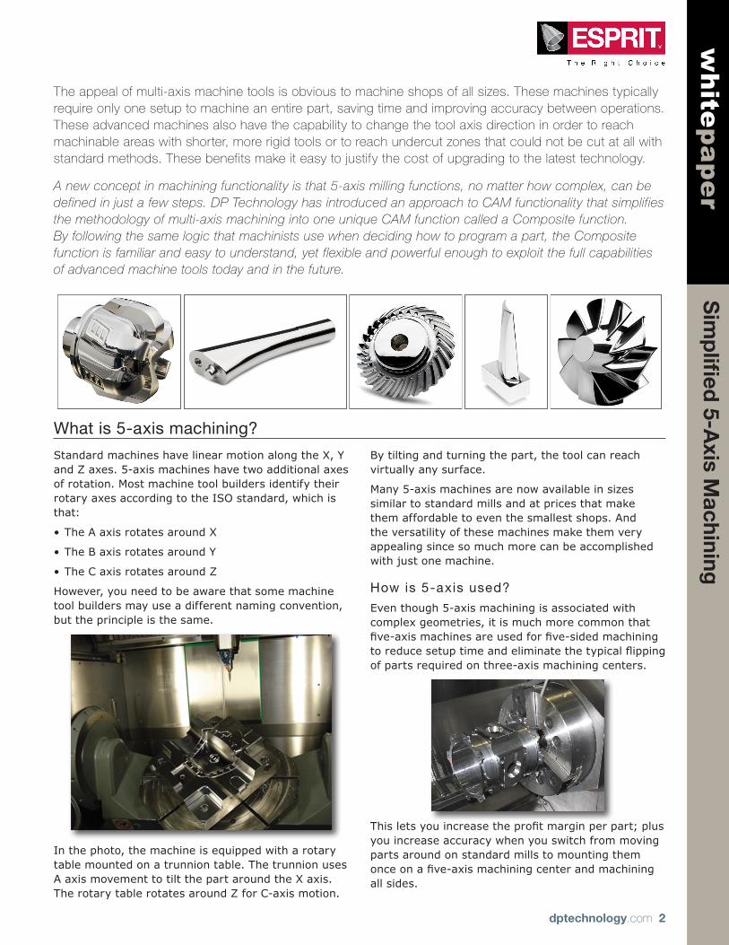
Standard machines have linear motion along the X, Y and Z axes. 5-axis machines have two additional axes of rotation. Most machine tool builders identify their rotary axes according to the ISO standard, which is that:
•The A axis rotates around X
•The B axis rotates around Y
•The C axis rotates around Z
However, you need to be aware that some machine tool builders may use a different naming convention, but the principle is the same.
In the photo, the machine is equipped with a rotary table mounted on a trunnion table. The trunnion uses A axis movement to tilt the part around the X axis. The rotary table rotates around Z for C-axis motion.
By tilting and turning the part, the tool can reach virtually any surface.
Many 5-axis machines are now available in sizes similar to standard mills and at prices that make them affordable to even the smallest shops. And the versatility of these machines make them very appealing since so much more can be accomplished with just one machine.
How is 5-axis used?
Even though 5-axis machining is associated with complex geometries, it is much more common that five-axismachinesareusedforfive-sidedmachiningtoreducesetuptimeandeliminatethetypicalflippingof parts required on three-axis machining centers.
Thisletsyouincreasetheprofitmarginperpart;plusyou increase accuracy when you switch from moving parts around on standard mills to mounting them onceonafive-axismachiningcenterandmachiningall sides.
The appeal of multi-axis machine tools is obvious to machine shops of all sizes. These machines typically require only one setup to machine an entire part, saving time and improving accuracy between operations. These advanced machines also have the capability to change the tool axis direction in order to reach machinable areas with shorter, more rigid tools or to reach undercut zones that could not be cut at all with standard methods. These benefits make it easy to justify the cost of upgrading to the latest technology.
A new concept in machining functionality is that 5-axis milling functions, no matter how complex, can be defined in just a few steps. DP Technology has introduced an approach to CAM functionality that simplifies the methodology of multi-axis machining into one unique CAM function called a Composite function. By following the same logic that machinists use when deciding how to program a part, the Composite function is familiar and easy to understand, yet flexible and powerful enough to exploit the full capabilities of advanced machine tools today and in the future.

Sim
plifi
ed 5-A
xis Machining
dptechnology.com 3
whitepaper
5-axis machine configurations
Let’stakealookatsomecommonmachineconfigurations.
Table /Table Table /Tool Table /Tool (mil l-turn ) Tool /ToolBoth rotary axes are in the table
One rotary axis is in the table, the other axis is in the tool
One rotary axis is in the turning spindle, the other axis in the tool
Both rotary axes are in the tool
Inthefirstexample,thetworotaryaxesarelocatedin the table. The B axis tilts and the C axis rotates the part. Linear motion is handled by the milling head.
In the second example, the table still rotates in C but now the tilt is in the tool.
Looking at a table/tool combination on a mill-turn, the turning spindle becomes the C-axis to rotate the part and the tilt of the tool is controlled by the B-axis. The linear axes are located differently on a lathe, with the Z axis positioned horizontally along the spindle axis instead of vertically along the tool axis.
In the last example, the two rotary axes are located in the milling head to rotate and tilt the tool into any position.
Sim
plifi
ed 5-A
xis Machining
dptechnology.com 4
whitepaper
What can 5-axis do?
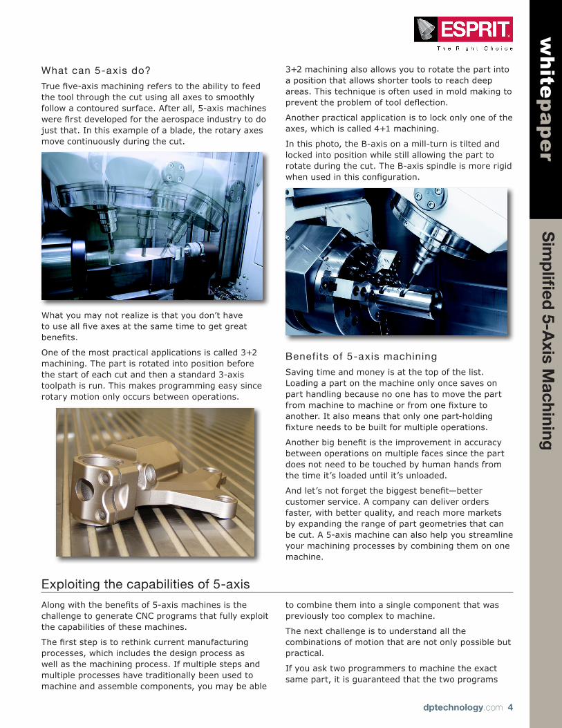
Truefive-axismachiningreferstotheabilitytofeedthe tool through the cut using all axes to smoothly follow a contoured surface. After all, 5-axis machines werefirstdevelopedfortheaerospaceindustrytodojust that. In this example of a blade, the rotary axes move continuously during the cut.
What you may not realize is that you don’t have touseallfiveaxesatthesametimetogetgreatbenefits.
One of the most practical applications is called 3+2 machining. The part is rotated into position before the start of each cut and then a standard 3-axis toolpath is run. This makes programming easy since rotary motion only occurs between operations.
3+2 machining also allows you to rotate the part into a position that allows shorter tools to reach deep areas. This technique is often used in mold making to preventtheproblemoftooldeflection.
Another practical application is to lock only one of the axes, which is called 4+1 machining.
In this photo, the B-axis on a mill-turn is tilted and locked into position while still allowing the part to rotate during the cut. The B-axis spindle is more rigid whenusedinthisconfiguration.
Benefits of 5-axis machining
Saving time and money is at the top of the list. Loading a part on the machine only once saves on part handling because no one has to move the part frommachinetomachineorfromonefixturetoanother. It also means that only one part-holding fixtureneedstobebuiltformultipleoperations.
Anotherbigbenefitistheimprovementinaccuracybetween operations on multiple faces since the part does not need to be touched by human hands from the time it’s loaded until it’s unloaded.
Andlet’snotforgetthebiggestbenefit—bettercustomer service. A company can deliver orders faster, with better quality, and reach more markets by expanding the range of part geometries that can be cut. A 5-axis machine can also help you streamline your machining processes by combining them on one machine.
Exploiting the capabilities of 5-axis
Alongwiththebenefitsof5-axismachinesisthechallenge to generate CNC programs that fully exploit the capabilities of these machines.
Thefirststepistorethinkcurrentmanufacturingprocesses, which includes the design process as well as the machining process. If multiple steps and multiple processes have traditionally been used to machine and assemble components, you may be able
to combine them into a single component that was previously too complex to machine.
The next challenge is to understand all the combinations of motion that are not only possible but practical.
If you ask two programmers to machine the exact same part, it is guaranteed that the two programs

Sim
plifi
ed 5-A
xis Machining
dptechnology.com 5
whitepaper
will be different because each person will attack the part from different directions. But remember that both programs will ultimately produce the same part, so the primary goal is to use the machine motion as efficientlyaspossible.
A critical challenge is to avoid collisions between moving components. The smallest programming error can generate costly damages because the materials, high precision tools, and accessories for these advanced machine tools can be quite expensive.
Andfinallyyouneedtostaywithinthelimitsofthe machine. There are physical limits on how far each axis can travel and there are limits on just how fast those axes can move in relation to one another. Linear motion is always faster and more accurate than rotary motion, so you need to control acceleration to prevent backlash when an axis moves too fast.
How can a CAM system help?
A CAM system can make the programming process easier by examining how the best machinists go about their work and then embedding that logic into the software.
Using the same logic as machinists lets the system provide guidance along the way for new programmers and provides a familiar environment for experienced programmers. But guidance must never be used to impose limitations. 5-axis programming can be compared to the artistic process of sculpting, which means that programmers must have creative freedom when deciding how to cut a part.
CAM systems also provide a risk-free proving ground for watching every movement of the machine. Every machinecomponent,everymovementcanbedefined
in the CAM system and then run in realtime on the computer. The advantage is that there are no doors or coolant to impede the view and you are not taking up valuable machine time.
Getting the best NC output happens when the software developer works in partnership with machine tool builders. These partnerships let the companies work together on real machines and real parts to develop better toolpath and better NC output to produce exactly what you see on your screen. Whenyoureceiveoneofthesepostprocessorfiles,you know that it’s been tested on the same machine sittingonyourshopfloor.
A simplif ied approach
The key to creating an elegant solution is to start by throwing away the idea that each type of 5-axis work needs a specialized function. That approach is confusing and unnecessary.
A simpler approach is to create a single function that meets the needs of the majority of 5-axis work.

Sim
plifi
ed 5-A
xis Machining
dptechnology.com 6
whitepaperTo simplify software development, the Composite
function is composed of a set of interlocking modules, somewhat like building blocks. Each module is designed to perform well separately and together.
The modular design of the software allows for easy testing and expansion when technology changes in the future.
This type of software development is not only faster to implement, it results in a more reliable software.
Another way to simplify the software is to design an interface that responds intelligently to the choices being made. The interface should be designed to only display options that apply to the current work situation.
For example, a common tool strategy is to keep the tool axis normal to the model at all times. In the interface, there are three options for this strategy that let the user control the forward and sideways tilt of the tool.
If the user changes that strategy to one that has the tool follow a cuve, new options display that let the user control how the tool will travel along that curve.
If the user again changes the strategy to orient the toolaxisthroughafixedpoint,theoptionschangetoallow the selection of the location and direction of the point.
This step-by-step guidance helps the user avoid errors without imposing limitations.
5 Machining Patterns
4 Tool Axis
StrategiesLinksCollision
Detection
6 Machining Patterns
5 Tool Axis
StrategiesCollision Detection
Links
Acceleration Control
Point Distribution
Sim
plifi
ed 5-A
xis Machining
dptechnology.com 7
whitepaper
Simplifiled CAM for 5-axis
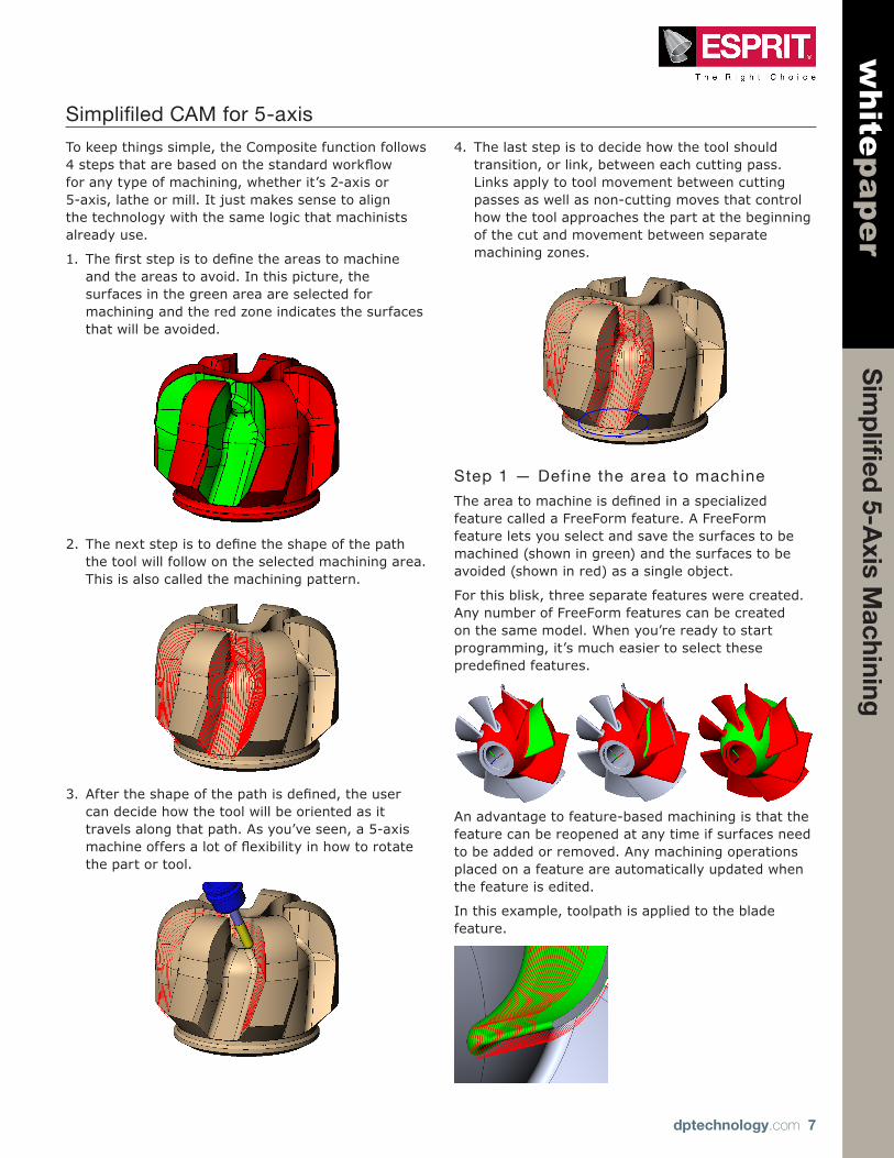
To keep things simple, the Composite function follows 4stepsthatarebasedonthestandardworkflowfor any type of machining, whether it’s 2-axis or 5-axis, lathe or mill. It just makes sense to align the technology with the same logic that machinists already use.
1. Thefirststepistodefinetheareastomachineand the areas to avoid. In this picture, the surfaces in the green area are selected for machining and the red zone indicates the surfaces that will be avoided.
2. Thenextstepistodefinetheshapeofthepaththe tool will follow on the selected machining area. This is also called the machining pattern.
3. Aftertheshapeofthepathisdefined,theusercan decide how the tool will be oriented as it travels along that path. As you’ve seen, a 5-axis machineoffersalotofflexibilityinhowtorotatethe part or tool.
4. The last step is to decide how the tool should transition, or link, between each cutting pass. Links apply to tool movement between cutting passes as well as non-cutting moves that control how the tool approaches the part at the beginning of the cut and movement between separate machining zones.
Step 1 — Define the area to machine
Theareatomachineisdefinedinaspecializedfeature called a FreeForm feature. A FreeForm feature lets you select and save the surfaces to be machined (shown in green) and the surfaces to be avoided (shown in red) as a single object.
For this blisk, three separate features were created. Any number of FreeForm features can be created on the same model. When you’re ready to start programming, it’s much easier to select these predefinedfeatures.
An advantage to feature-based machining is that the feature can be reopened at any time if surfaces need to be added or removed. Any machining operations placed on a feature are automatically updated when the feature is edited.
In this example, toolpath is applied to the blade feature.

Sim
plifi
ed 5-A
xis Machining
dptechnology.com 8
whitepaper
When the feature is edited to remove a face, the system detects the change and updates the toolpath.
Step 2 — Define the shape of the tool path
Nowthattheareatomachineisdefined,thenextstep is to decide what the toolpath will look like on that area. The Composite function includes 6 types of machining patterns that are common to multi-axis machining.
•Parametric Pattern
•Project Parametric Pattern
•Project Spiral
•Parallel Planes
•Planes Intersection with Spine Curve
•Contour Offset
Let’s discuss each pattern and its typical application.
Parametric toolpath
The preferred toolpath for contoured surfaces is a parametric pattern because parametric machining followsthenaturalflowlinesofthesurface.
The Composite function has two options for parametric machining.
TheParametricPatternoptionusestheflowlinesfrom a surface on the model itself.
The Project Parametric Pattern option projects the flowlinesofaseparatesurfaceontothemodel.
Foreitheroption,theparametricflowlinesareextracted from only one surface.
Whenyoumachinedirectlyfromtheflowlinesonthemodel, the quality of the machining depends largely on the quality of the original CAD model. As long astheflowlinesintheCADmodelaresmoothandcontinuous, the toolpath will be too.
But CAD models aren’t always perfect.
Inthismodelyoucanseethattheflowlinesonthefaces are not continuously aligned. The tool will not be able to make a smooth transition from one face to thenextbecauseofthemismatchedflowlines.
This annoying problem was the impetus for the development of the Knitted Surface function in ESPRIT. The knitted surface shown below overcomes the problem of misaligned faces by creating a single continuous surface from any number of faces on the solid model.

Sim
plifi
ed 5-A
xis Machining
dptechnology.com 9
whitepaper
The knitted surface can then be used as a projection surface to drive a parametric machining pattern on the underlying model. That way, smooth and continuous toolpath can be generated without changing the original part model.
Spiral toolpath
Spiralmachiningalsousestheprojectedflowlinesofa separate surface to produce toolpath in the shape of a continuous spiral. The only difference is that spiral toolpath is always used on a closed shape.
In this example, a knitted surface was used as the projection surface for all the underlying faces.
Spiral toolpath is also useful for projecting cutting passes onto a model with a cylindrical shape.
Abigbenefitofspiralpassesisthatthecutterstaysin contact with the part at all times. This makes it ideal for high-speed machining because there are no sharp transitions in the toolpath.
Planar toolpath
One of the oldest and most classic machining patterns is the Planar option. Planar toolpath has relatively uniform spacing between cutting passes and is used when you want to start cutting at one endofapartandstopcuttingataspecifieddistance.
The Composite function supports classic planar cuttingthatusesavectortodefinethedirectionforthe evenly-spaced cutting passes.
Another option is to select a drive curve instead of a straight vector. In that case, the distance between cutting passes is calculated by spacing the slice planes for the planar cuts at equal distances along the curve.
Offset toolpath
Offset toolpath is another classic machining pattern. Thispatternworkswellonareaswithadefinedouterboundary.
The shape of the outer boundary is calculated and then progressively offset towards the center.
Sim
plifi
ed 5-A
xis Machining
dptechnology.com 10
whitepaper
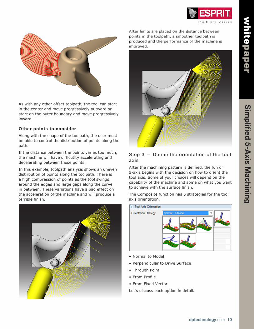
As with any other offset toolpath, the tool can start in the center and move progressively outward or start on the outer boundary and move progressively inward.
Other points to consider
Along with the shape of the toolpath, the user must be able to control the distribution of points along the path.
If the distance between the points varies too much, themachinewillhavedifficutltyacceleratinganddecelerating between those points.
In this example, toolpath analysis shows an uneven distribution of points along the toolpath. There is a high compression of points as the tool swings around the edges and large gaps along the curve in between. These variations have a bad effect on the acceleration of the machine and will produce a terriblefinish.
After limits are placed on the distance between points in the toolpath, a smoother toolpath is produced and the performance of the machine is improved.
Step 3 — Define the orientation of the tool axis
Afterthemachiningpatternisdefined,thefunof5-axis begins with the decision on how to orient the tool axis. Some of your choices will depend on the capability of the machine and some on what you want toachievewiththesurfacefinish.
The Composite function has 5 strategies for the tool axis orientation.
•Normal to Model
•Perpendicular to Drive Surface
•Through Point
•FromProfile
•From Fixed Vector
Let’s discuss each option in detail.
Sim
plifi
ed 5-A
xis Machining
dptechnology.com 11
whitepaper
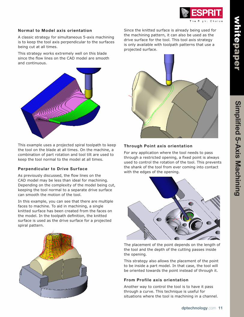
Normal to Model axis orientat ion
A classic strategy for simultaneous 5-axis machining is to keep the tool axis perpendicular to the surfaces being cut at all times.
This strategy works extremely well on this blade sincetheflowlinesontheCADmodelaresmoothand continuous.
This example uses a projected spiral toolpath to keep the tool on the blade at all times. On the machine, a combination of part rotation and tool tilt are used to keep the tool normal to the model at all times.
Perpendicular to Drive Sur face
Aspreviouslydiscussed,theflowlinesontheCAD model may be less than ideal for machining. Depending on the complexity of the model being cut, keeping the tool normal to a separate drive surface can smooth the motion of the tool.
In this example, you can see that there are multiple faces to machine. To aid in machining, a single knitted surface has been created from the faces on themodel.Inthetoolpathdefinition,theknittedsurface is used as the drive surface for a projected spiral pattern.
Since the knitted surface is already being used for the machining pattern, it can also be used as the drive surface for the tool. This tool axis strategy is only available with toolpath patterns that use a projected surface.
Through Point axis orientat ion
For any application where the tool needs to pass througharestrictedopening,afixedpointisalwaysused to control the rotation of the tool. This prevents the shank of the tool from ever coming into contact with the edges of the opening.
The placement of the point depends on the length of the tool and the depth of the cutting passes inside the opening.
This strategy also allows the placement of the point to be inside a part model. In that case, the tool will be oriented towards the point instead of through it.
From Profi le axis orientat ion
Another way to control the tool is to have it pass through a curve. This technique is useful for situations where the tool is machining in a channel.
Sim
plifi
ed 5-A
xis Machining
dptechnology.com 12
whitepaper
When you use a curve to control the tool axis you have two options.
The tool can pass through a curve that lies outside the model.
Or the tool can be oriented toward a curve that lies inside the model.
Additional options help control how the system calculates the relationship between the points on the drive curve and the contact point of the tool on the model.
Inthefirstexample,anopencurveisusedtocontrolthe orientation of the tool as it cuts the channel. In that case, the best strategy is to synchronize the pointsbetweentheprofileandthetoolpathsothatthe tool will be at the midpoint of the curve halfway along cutting the channel.
In the second example, the curve passes through the center of the cylinder. In this case, the best strategy is to maintain the minimum distance between the curve and the contact point of the tool.
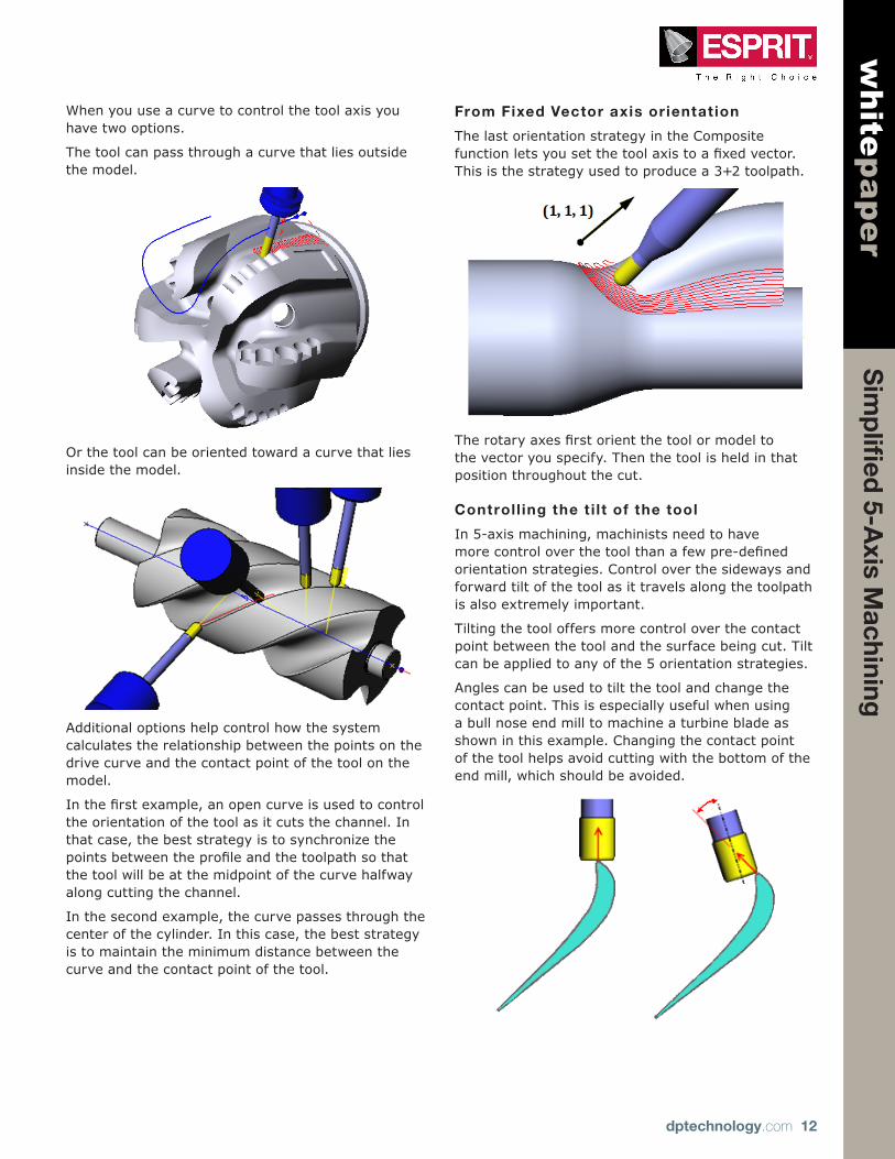
From Fixed Vector axis orientat ion
The last orientation strategy in the Composite functionletsyousetthetoolaxistoafixedvector.This is the strategy used to produce a 3+2 toolpath.
Therotaryaxesfirstorientthetoolormodeltothe vector you specify. Then the tool is held in that position throughout the cut.
Controll ing the t i l t of the tool
In 5-axis machining, machinists need to have morecontroloverthetoolthanafewpre-definedorientation strategies. Control over the sideways and forward tilt of the tool as it travels along the toolpath is also extremely important.
Tilting the tool offers more control over the contact point between the tool and the surface being cut. Tilt can be applied to any of the 5 orientation strategies.
Angles can be used to tilt the tool and change the contact point. This is especially useful when using a bull nose end mill to machine a turbine blade as shown in this example. Changing the contact point of the tool helps avoid cutting with the bottom of the end mill, which should be avoided.
Sim
plifi
ed 5-A
xis Machining
dptechnology.com 13
whitepaper
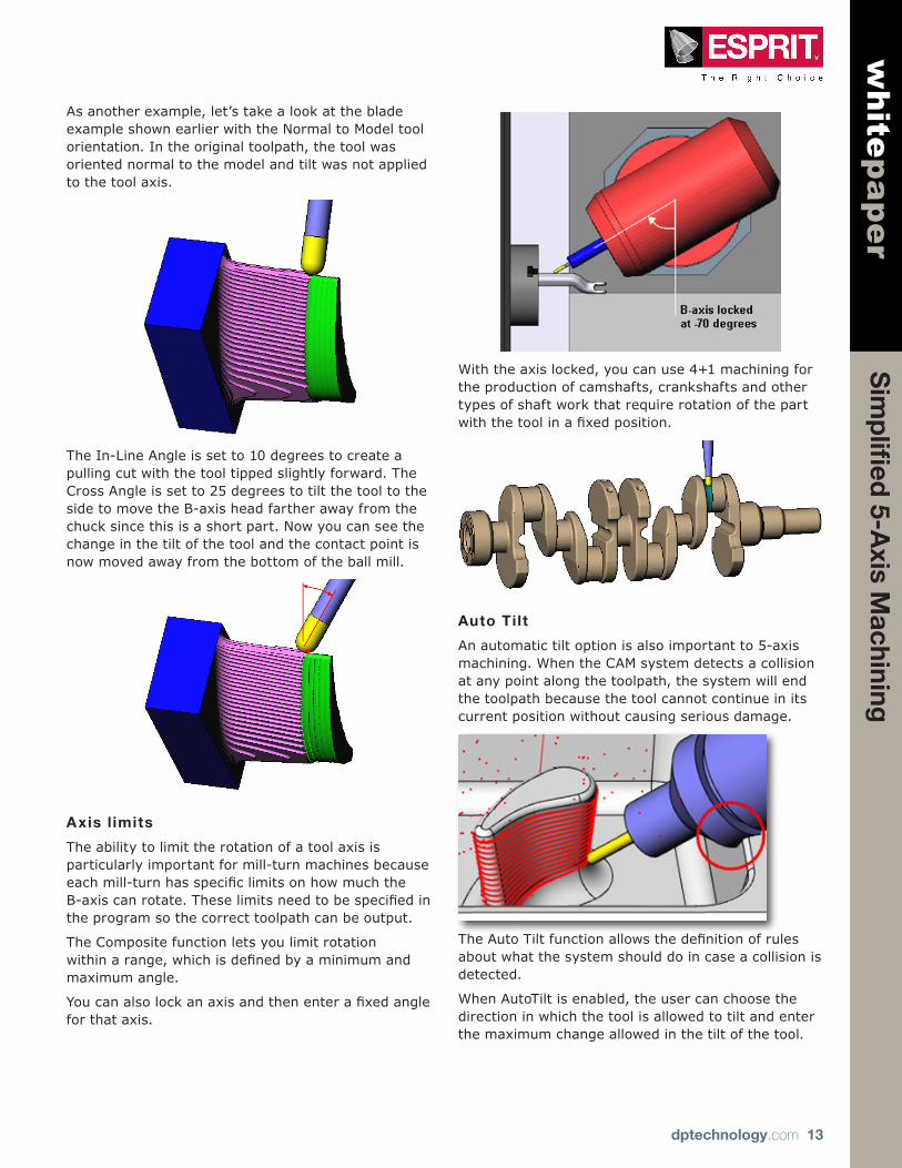
As another example, let’s take a look at the blade example shown earlier with the Normal to Model tool orientation. In the original toolpath, the tool was oriented normal to the model and tilt was not applied to the tool axis.
The In-Line Angle is set to 10 degrees to create a pulling cut with the tool tipped slightly forward. The Cross Angle is set to 25 degrees to tilt the tool to the side to move the B-axis head farther away from the chuck since this is a short part. Now you can see the change in the tilt of the tool and the contact point is now moved away from the bottom of the ball mill.
Axis l imits
The ability to limit the rotation of a tool axis is particularly important for mill-turn machines because eachmill-turnhasspecificlimitsonhowmuchtheB-axiscanrotate.Theselimitsneedtobespecifiedinthe program so the correct toolpath can be output.
The Composite function lets you limit rotation withinarange,whichisdefinedbyaminimumandmaximum angle.
Youcanalsolockanaxisandthenenterafixedanglefor that axis.
With the axis locked, you can use 4+1 machining for the production of camshafts, crankshafts and other types of shaft work that require rotation of the part withthetoolinafixedposition.
Auto Tilt
An automatic tilt option is also important to 5-axis machining. When the CAM system detects a collision at any point along the toolpath, the system will end the toolpath because the tool cannot continue in its current position without causing serious damage.
TheAutoTiltfunctionallowsthedefinitionofrulesabout what the system should do in case a collision is detected.
When AutoTilt is enabled, the user can choose the direction in which the tool is allowed to tilt and enter the maximum change allowed in the tilt of the tool.
Sim
plifi
ed 5-A
xis Machining
dptechnology.com 14
whitepaper
The AutoTilt function allows the rest of the area to be machined without having to create a second toolpath or having to start over with a different tool orientation for the entire toolpath.
Step 4 — Define the linking strategy
Thefinalstepinthisprocessistodefinethemovesthe tool makes between the actual cutting passes. For the smoothest surface possible, the manner in which the tool moves from the end of one cutting passtothestartofthenextrequiresfinesseandcontrol.
Multiple choices in a prioritized list take the guesswork out of which linking methods are preferred by the machinist.
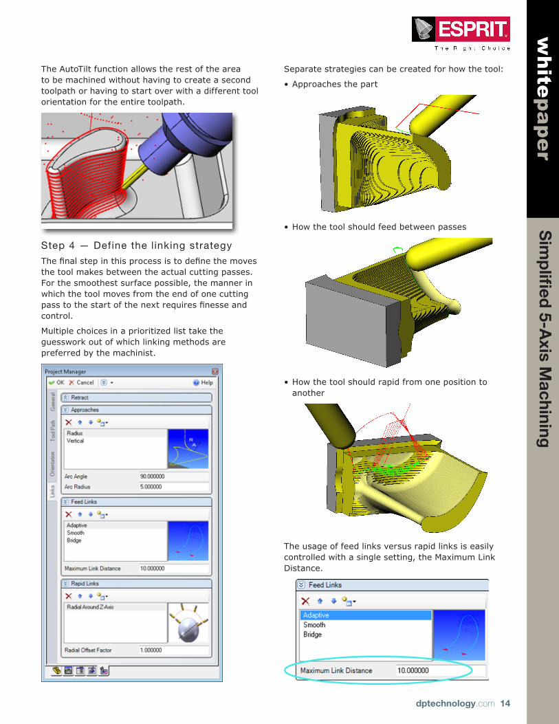
Separate strategies can be created for how the tool:
•Approaches the part
•How the tool should feed between passes
•How the tool should rapid from one position to another
The usage of feed links versus rapid links is easily controlled with a single setting, the Maximum Link Distance.

dptechnology.com 15
Sim
plifi
ed 5-A
xis Machining
whitepaper
DP Technology Corp.1150 Avenida AcasoCamarillo, CA93012 USATel: + 1 800 627 8479Outside the US: + 1 805 388 6000Email: [email protected]
About DP TechnologyDP Technology is a leading developer and supplier of computer-aided manufacturing (CAM) software for a full range of machine tool applications. ESPRIT, DP Technology’s flagship product, is a powerful, high-performance, full-spectrum programming system for milling, turning, wire EDM, and multitasking machine tools. ESPRIT embodies DP Technology’s passion for excellence and its vision of technology’s potential.
The opinions, solutions, and advice in this article are from the experience of Ann Mazakas and is not intended as an endorsement of any product. The accuracy of the information in this article is based on Ann Mazakas’ knowledge at the time of writing.
Copyright © 2011 DP Technology Corp. All rights reserved.ESPRIT is a registered trademark of DP Technology Corp.
About the authorAnn Mazakas is Manager of Technical Communications at DP Technology Corp. Ann has an extensive background in CAD/CAM systems, design engineering, and metalworking. She is the author of numerous technical articles on issues facing the manufacturing industry. With a passion for metalworking, she has been a writer and speaker since 1998.
Theuseronlyneedstodefineamaximumdistancefor feed moves and the system takes care of the rest. As soon as the system detects a gap between cutting passesthatislargerthantheuser-defineddistance,it will generate a rapid move.
Priorit ized l ists
Most CAM systems offer several options for linking moves but the user typically has to choose just one of those. With 5-axis machining there are just too many variables with the machine motion to limit the choices for tool transitioning moves.
The logical answer is to let the programmer choose a favorite, a next favorite, and so on.
For example, top priority can be given to a linking method that keeps the tool on the surface the entire time. But if that method is not possible then the system can look at the user’s list of preferences to see how to behave next.
As a second priority, the user prefers a link that lifts the tool off the surface with a radius move and then returns to the surface at the next cut with a tangent radiused move. A third priority can be given to a link that lifts the tool completely off the surface.
That way, the user can prioritize linking methods and there is less chance that the machining operation will fail or cause gouging because of an inappropriate move when the tool repositions.
Unlimited creativity
With a single Composite function, you can choose any one of the available machining patterns and any one of the available tool orientation strategies to create your own customized toolpath.
Add to that the ability to lock an axis and your toolpath is quickly converted to a 4+1 application. Or
lock 2 axes to create a 3+2 program. The choice is up to you.
TheCompositefunctiongivesyoutheflexibilitytotrydifferent machining techniques without ever having to re-enter data about the part.
Roadmap to the future
From the viewpoint of the software developer, creating a single milling function that meets the needs of machinists today and in the future requires an in-depth analysis of each step used in the process of generating multi-axis tool path.
It also requires real-world experience working with the types of multi-axis machines that are used every dayontheshopfloorplusthenewtechnologybeingdeveloped by machine tool builders.
This in-depth analysis led to the development of the component-based Composite function,
allowing a single CAM function to meet the needs of the majority of 5-axis work. The components of the Composite function have also become the foundation for more advanced 5-axis functions, allowing DP Technology to quickly offer specialized 5-axisfunctionssuchasturbinebladefinishingwiththe same reliability and familiar interface as the Composite function.
This type of thinking marks a departure from traditional CAM software development so that a CAM system can easily keep pace with the rapidly evolving multi-axis technology.