Embed Size (px)
Citation preview

Page 1 of 14
SIMPLE AND
EFFECTIVE
SOLUTION FOR
MEDIUM SPAN
RAILWAY BRIDGE
FILLER BEAM
COMPOSITE DECKS
– REVIEW AND
EUROPEAN
EXPERIENCE
RICCARDO ZANON
TONI DEMARCO
BIOGRAPHY
Riccardo Zanon, S.E., MBA, is Head of Technical Sales for
Eurostructures Beam Finishing
Centre in Luxembourg, within
ArcelorMittal Europe – Sections
& Merchant Bars. Previously he
held positions in the R&D
Centre and Technical Advisory
Department at ArcelorMittal
Europe. He is a graduate of the
Technische Universität Dresden
(Germany) and of the Sacred
Heart J. Welch University
(Connecticut, US).
Toni Demarco, S.E., is Head of
Eurostructures Beam Finishing
Centre in Luxembourg, within
ArcelorMittal Europe – Sections
& Merchant Bars. Previously he
held positions in the R&D
Centre, Sales Manager for Sheet
Piles, and Technical Advisory
Department for Sections and
Merchant Bars at ArcelorMittal
Europe. He is a graduate of the
Universität Karlsruhe
(Germany).
SUMMARY
In the framework of a politic
of large structural investment
plan, Europe has been
developing its infrastructure
network over the past decades to
allow for a better integration
amongst countries. Whereas for
the roadway network the efforts
have been concentrated in
Eastern Europe, the public rail
network of Western and Central
Europe is undergoing a vast
campaign of renewal and
modernization.
When it comes to railway
infrastructure, the classical
european steel-concrete solution
is the filler beam deck which is
well-known and widely used for
small and medium span bridges.
According some estimations this
structural typology corresponds
to 10% up to 25% of the
existing bridge stock depending
on the country.
On one hand their use has
decreased for simple structures
faced to prestressed concrete
decks, but on the other hand
they are now implemented for a
wider range of spans and train
speeds as well as for integral
bridges. The paper will focus on
the structural concept, the
design, the execution and the
assessment of this bridge deck
typology.
Page 2 of 14
Simple and effective solution for medium span railway bridges
Filler beam composite decks – review and European experience
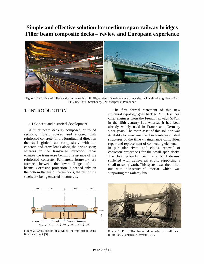
Figure 1: Left: view of rolled section at the rolling mill; Right: view of steel-concrete composite deck with rolled girders – East
LGV line Paris- Strasbourg, RN3 overpass at Pomponne
1. INTRODUCTION
1.1 Concept and historical development
A filler beam deck is composed of rolled
sections, closely spaced and encased with
reinforced concrete. In the longitudinal direction
the steel girders act compositely with the
concrete and carry loads along the bridge span;
whereas in the transverse direction, rebar
ensures the transverse bending resistance of the
reinforced concrete. Permanent formwork are
foreseen between the lower flanges of the
beams. Corrosion protection is needed only on
the bottom flanges of the sections, the rest of the
steelwork being encased in concrete.
Figure 2: Cross section of a typical railway bridge using
filler beam deck [3].
The first formal statement of this new
structural typology goes back to Mr. Descubes,
chief engineer from the French railways SNCF,
in the 19th century [1], whereas it had been
already widely used in France and Germany
since years. The main asset of this solution was
its ability to overcome the disadvantages of steel
structures of the time (maintenance difficulties,
repair and replacement of connecting elements –
in particular rivets and clouts, renewal of
corrosion protection) for the small span decks.
The first projects used rails or H-beams,
stiffened with transversal struts, supporting a
small masonry vault. This system was then filled
out with non-structural mortar which was
supporting the railway line.
Figure 3: First filler beam bridge with 1m tall beam
(HEB1000), Fentange, Germany 1917.

Page 3 of 14
Figure 4: Cross-section still in use: line Basel-Olten, km
24.216, 1902, Switzerland.
For several decades the beams were designed
as non-composite in the longitudinal direction.
But then already in the first half of the 20th
century the calculation developed to a composite
cross-section design for the longitudinal
direction [1].
1.2 Field of application
Originally developed only for railway
bridges, over the last few decades filler beam
decks have also been widely and effectively
used for road bridges. It offers a robust, simple
and durable construction which does not require
any highly specialised labour. Due to their high
load carrying capacity, there are now a large
number of decks of this type still in use
evenwhere the service conditions have changed.
Filler beam construction is today mainly used:
for decks with restricted construction depth;
for bridges crossing roads as erection is both
quick and easy; temporary supports and
falsework are not required, so that disruption
of traffic can be avoided to a large extent;
when replacing decks in existing structures:
the shallow slab thickness facilitates adaptation
to the geometrical constraints. Furthermore,
the monolithic construction is also well suited
to erection by launching.
The span covered by filler beam decks range
(figures in brackets apply for continuous
multiple span bridges):
up to 40 (50) meters for road bridges;
up to 30 (35) meters for railway bridges.
1.3 Availability of strucural shapes
Major structural component of this typology
are H-structural shapes, first out of Iron and then
out of Modern Steel. Rolled structural shapes (L,
I, H, U) were developed at the end of the 19th
century, answering the need to simplify shapes
built up from plates assembled together by
rivets. The advantages in terms of weight
savings, fabrication simplification and cost
reduction were integral to the acceptance of
rolled shapes in every field. Today, the
geometric range of available H structural shapes
is extensive (beam height 80…1150mm, flange
width 50…450mm, flange thickness
4…140mm) with a well-established presence of
production sites around the world [5], [6],
making structural shapes a well-known standard
products known by Engineers and Steel
Fabricators.
In addition to expansion of geometric
properties, the development of optimized rolling
procedures occurred over several decades. Since
the 1990, thermo-mechanical rolling has become
a standard for the most advanced plants in
Western Europe. Proper to this In order to
enhance the benefits of thermomechanical
rolling, the quenching and self-tempering
process (QST) was developed specifically for
sections with thick flanges. Implementing this
innovative procedure, made it possible to
economically obtain high steel strengths (up to
485MPa) for heavy sections without the costly
addition of alloying elements [8], [9].
Figure 5: Availability of Structural shapes [15].
Page 4 of 14
2. DESIGN
2.1 European normative approach
Filler Beam Decks are designed in Europe
according EN1994-2 : 2005 [18], dedicated to
steel-concrete composite bridges. A chapter for
the design of the cross-section is the 6.3,
whereas other constructive and complementary
rules are in chapter 5 and chapter 7. Nonetheless
other standard published by National Railway
Authorithies are interacting with the Eurocode
and have to be considered.
The new version of the French standard
„IN0035, Livret 2.32“ [22] contains only rules
about the steel choice, fabrication and corrosion
protection, whereas the design is done according
Eurocode completed by the national Annexes.
The German standard „DB Ril 804“ [23]
includes some complementary rules but which
are in general simplifying the design. It has to be
underlined that a a recent work in collaboration
between the steel industry and the railway
authorithies has published a whole book of
solutions which are already validated. The
Italian technical specification [24] also contains
several tables of pre-engineered solutions,
having said that in this country mainly simply
supported decks have been built. The solutions
have been designed at the elastic limit state since
the deflection limit is governing the design for
the configurations which have been studied.
2.2 Cross-section design
The calculation allows only for rolled
sections (or eventually with welded sections
with the same geometric dimensions). A
skewness up to 30° is allowed, whereas for or
beams with curvature in plan a complex model
shall be adopted.
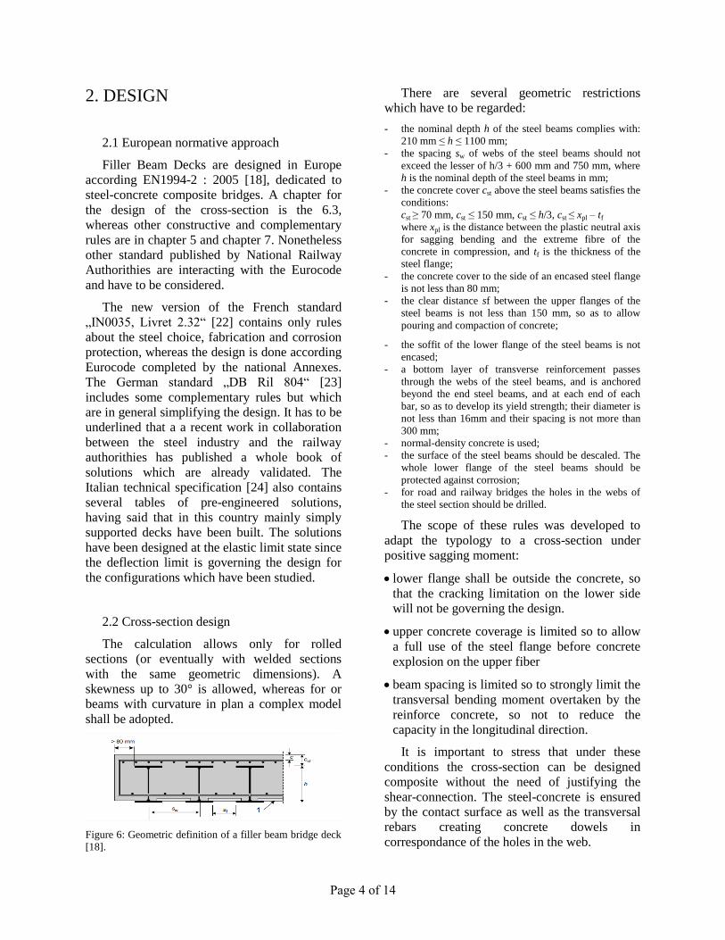
Figure 6: Geometric definition of a filler beam bridge deck
[18].
There are several geometric restrictions
which have to be regarded:
- the nominal depth h of the steel beams complies with:
210 mm ≤ h ≤ 1100 mm;
- the spacing sw of webs of the steel beams should not
exceed the lesser of h/3 + 600 mm and 750 mm, where
h is the nominal depth of the steel beams in mm;
- the concrete cover cst above the steel beams satisfies the
conditions:
cst ≥ 70 mm, cst ≤ 150 mm, cst ≤ h/3, cst ≤ xpl – tf
where xpl is the distance between the plastic neutral axis
for sagging bending and the extreme fibre of the
concrete in compression, and tf is the thickness of the
steel flange;
- the concrete cover to the side of an encased steel flange
is not less than 80 mm;
- the clear distance sf between the upper flanges of the
steel beams is not less than 150 mm, so as to allow
pouring and compaction of concrete;
- the soffit of the lower flange of the steel beams is not
encased;
- a bottom layer of transverse reinforcement passes
through the webs of the steel beams, and is anchored
beyond the end steel beams, and at each end of each
bar, so as to develop its yield strength; their diameter is
not less than 16mm and their spacing is not more than
300 mm;
- normal-density concrete is used;
- the surface of the steel beams should be descaled. The
whole lower flange of the steel beams should be
protected against corrosion;
- for road and railway bridges the holes in the webs of
the steel section should be drilled.
The scope of these rules was developed to
adapt the typology to a cross-section under
positive sagging moment:
lower flange shall be outside the concrete, so
that the cracking limitation on the lower side
will not be governing the design.
upper concrete coverage is limited so to allow
a full use of the steel flange before concrete
explosion on the upper fiber
beam spacing is limited so to strongly limit the
transversal bending moment overtaken by the
reinforce concrete, so not to reduce the
capacity in the longitudinal direction.
It is important to stress that under these
conditions the cross-section can be designed
composite without the need of justifying the
shear-connection. The steel-concrete is ensured
by the contact surface as well as the transversal
rebars creating concrete dowels in
correspondance of the holes in the web.

Page 5 of 14
Figure 7: Mechanical work of a bar in concrete [10]
Under the condition that the cross-section
respect the limit for the class 1 or 2 concerning
the lower flange (which is the standard case), the
verification under bending moment is done at
the plastic limit state taking into account the
steelwork, the concrete and the rebars in tension.
Conversely the shear action is attributed only to
the steel beams; anyway in this structural
typology this never becomes a design issue. In
transversal direction, the deck is calculated as a
traditional reinforced concrete plate. The
cracking limitation is done as if the non-
participating formwork was not there, whereas it
can be taken into account concerning the
reinforcement coverage.
Figure 8: Cross-section classification for filler beams [18]
In the final phase there is no danger of
instability as the steelwork is embedded in the
concrete. During the construction phase on the
contrary the steelwork is overtaking all the self-
weight including the fresh concrete. Therefore
the steel beams have to be verified and sufficient
anti-LTB devices are provided in terms of
temporary bracings and struts. Some pictures of
the most common devices are showed in the
chapter dedicated to the execution phase (see
Figure 17). Concerning the serviceability limit
state, all the usual stress limitation verifications
are lead as for a normal composite section. For
deformability checked one part of the cracked
concrete is taken into account (the inertia of the
concrete is calculated as the average of the non-
cracked cross-section and the inertia of the full
cross-section).
Figure 9: Calculation of sagging moment resistance [18]
Design according fatigue limit state is done
as usual, having noted that this is never
governing the dimensioning of the beams. In
fact there is no major fatigue detail so in the old
codes it was stated that fatigue verification could
be skipped provided that holes were drilled (not
punched) and deburbed, and continuity joints, if
any, are verified (in fact they can be located in
zone of low stress use).
2.3 Optimal choice of the steel grade
In Europe, rolled as well as plated girders for
bridges are usually constructed in steel grade
S355 [14] (comparable to Grade 50 in US). This
grade is quite common, eventually available on
stock, and implies well known and mastered
welding procedures. Using plates in higher steel
strength is not common for small to medium
span bridges, as the quantities are not sufficient
to order the plates directly at the mill (since the
tonnages is splitted on a wide range of
thicknesses, and in particular for the small
thicknesses).
When it comes to rolled girders in S460
(comparable to Grade 65), this option is well
established in the European practice and is
economical advantageous, as the high strength
can lead to weight savings in the design of the
structural system. In addition, when high-
strength sections are produced using a
quenching and self tempering process, the
members’ low-carbon content results in
improved weldability of the material. As a result
of the benefits of weight savings and simplifed
fabrication, rolled girders in high steel strength
have become a solution of choice for standard
small span bridges [5]. For road bridges rolled
girders in high strength steel are becoming a
standard. Conversely for railway bridges the
design is often governed by the deformability
checks so that the use of high strength steel is
not common.

Page 6 of 14
3. EXECUTION
3.1 Steel fabrication
In Europe major steel plants for rolled beams
have integrated beam centers which can take in
charge basic finishing such as cut-and-drill,
camber, welding and finishing of heavy
structural shapes as a service to the customer.
This appears to be very important in particular
for heavy shapes with long lengths, as this cut
down logistic costs and permits to develop
specific machinery and know-how in fabricating
this heavy section.
Steel girders for these decks are therefore
produced and fabricated directly at the steel
plant. As it comes of railway bridge application,
the steel is produced on a specific order in the
steel grade specific to the relative railway
authorities and then controlled and certified.
From the normative point of view, the
harmonized European standard for structural
steel (EN10025 : 2005 [19]) is completed by
national recommendations ([21], [22], [23])
which may specify additional testing such as
Ultrasonic testing to verify he internal
soundness, stricter surface requirements (less
imperfections or mechanical grinding) or stricter
chemical composition (in particular to avoid the
risk of fragility or inclusions).
Figure 10: Rolling of structural shapes out of Beam Blanks
Fabrication is executed in accordance to the
European standard for steel execution (EN1090-
2 : 2012 [20]), in the usual case according to the
Execution Class 3 (which is the second most
severe after the 4, applicable for special
structures and major bridgeworks). The first step
is to curve the structural shape in cold condition
to include the wished cambering form to
compensate deformations under self-weight.
Figure 11: Curving of tall beams in full length by means of
a gag press in cold condition
After being cut-to-length, holes are drilled in
the web to install stabilization systems and
transverse reinforcement. In average there are
between 5 and 10 holes per meter of beam with
diameters varying between 27 and 50mm
according to the needs. The holes and the cut
edges are grinded to avoid any mechanical crack
initiation as according to [20].
Figure 12: Cutting to exact length by saw blade, automatic
drilling in the web and in the flanges

Page 7 of 14
Corrosion protection is applied on the basis of
the international standard ISO EN 12944 [24]
but completed also by national standards (e.g.
[21], [22], [23]) which specify the system. Steel
is shot-blasted prior to fabrication so to allow for
surface controls and a proper fabrication.
Afterwards only the exposed lower flange and
the adjacent part of the web is treated and
prepared to achieve a high steel rugosity class
Sa3. The first layer is either a primer rich of zinc
or a hot zinc projection (also known as cold-
galvanizing) for a thickness between 80 and 120
micron depending on the system. On this most
important layer a thin layer on the edges as well
as to close the porosity is applied. Afterwards
several layers of epoxy organic coating, a top
coating (polyurethane) finish the system.
Figure 13: Automatic shot-blasting and manual application
of metallization and organic coating layers
3.2 Transportation
Fully finished beams are transported preferably
by railroad in order to decrease environmental
impact and freight costs. There is an important
know-how to tranport successfully long products
on the European railway network. Whereas 24m
is still standard length, up to 32-33m does not
represent major issues as the beams can still fit
on one standard wagon accompanied by an
empty shock wagon on top and on queue. The
topic becomes more challenging as the 35meter
length is exceeded, because the beams have to
stand on two different wagons. The record was
set in 2013 by trasporting filler beam girders
with lengths up to 60.6m.
Truck deliveries are also quite common and
have the main advantage to avoid maintenance
between the railway terminal and the
construction site. Longest filler beam girders
deliveries have been achieved in 2011 with
42.5m.
Figure 14: Exceptional rail transport of 54.16m already
coupled in the workshop, Railway Bridge at Boulevard Ney
a Paris, 2000, France
Figure 15: Exceptional rail transport of 39.7m beams with
curvature about weak axis with a radius of 354m, Roadway
Bridge RD257 in Arles, 2014, France
Figure 16: Exceptional road transport of 42.5m beams,
roadway Bridge B6N in Magdeburg, 2011, Germany.

Page 8 of 14
Figure 17: Fixing of bracing devices before erection
3.3 Erection and stabilization
Once beams are delivered on the construction
site, it is important to stabilize them by means of
temporary elements such as struts and cross
bracings. This is actually the only phase where
this robust deck typology can encur some risks
of instability, so it is very important not to skip
this verification to avoid catastrophic effects on
the constructions site.
Steel elements are typically erected by crane in
packages of several beams lifted together
directly into their final position on the bearings.
Lower reinforcement layer may be installed
before erection, whereas the standard practice is
to install after.
After installing some distancing elements
amongst the beam lines, concrete is poured on
the deck in several steps (at least 3: firstly just
about 10cm, afterwards up to the upper flange,
and finally to the final level). Repositioning of
the deck after concreting may be necessary for
the correct introduction of load onto supports.
Figure 18: Lifting of beam packages on bridge supports
Figure 19: Filler beam deck concreting
Figure 20: Filler beam deck during construction phase
3.4 Jobsite splice – Bolted connection
In case beams have to be spliced on the
jobsite to achieve a continuous girder, the easiest
and cheapest solution is usually to use cover
plates to be bolted on the flanges and on the web
of the structural shape. Other bolted connections
such as header plates are not suitable for this
kind of application and are not recommended.
Figure 21: Example of a bolted splice with cover plates

Page 9 of 14
When designing such detail, first of all it is
important to check the constructive details
because these plates have to fit in the system of
the transversal and longitudinal reinforcement,
let the place to support the formwork in
transversal direction, and of course allow for
some tolerances to be erected on the jobsite
condition. In particular with the use of tall
beams with long lengths, the fitting in on the
construction site may require some time.
Figure 22: Installing of filler beam girder with bolted
connection splice
Bolted connections subjected to fatigue have
to be designed as slip-resistant with high
strength preloaded bolts (8.8 or 10.9 class) [17].
Specific attention has to be concerned to the
friction surface, as the execution is linked with
the splip factor which has been taken in the
design note. There are 6 different options which
are possible in the future prEN1090-2,
nevertheless only two are relevant for slip-
resistant bolted connections (A or B,
correspondent to a slip factor 0.5 or 0.4) [20].
Table 1: Surface treatment classes in function of the design
slip factor [20]
3.5 Jobsite splice – Welded connection
The other option is of course to realize the
splice by means of a welded splice. The choice
of this option instead of the previous one is
typically linked with the habit of the
administration and the design office, as the two
possibilities have been successfully implemeted
for decades both for roadway and railway
bridges. Esthethic in this case is not a topic as
the splice is embedded in the concrete and only
the lower flange is visible.
Figure 23: Weld bevel preparation for a welded splice on
the construction site.
When welding together structural shape
particular attention has to be dedicated to the k-
zone where flange and web comes together [2].
In general the thicknesses of the flanges are not
more than 40…50mm (1.5…2 inches) so the
coping hole is not foreseen. Full penetration
welds are foreseen with access from both side
and root in the middle or 2/3 – 1/3 in the
material thickness. Welding is then checked
100% at Ultrasonic testing and Magnetoscopic
testing.
As a general case, the welded option is more
costly than the bolted splice version for this
bridge typology. Conversely as a major
advantage, there are more geometric tolerances
if the splice on the construction site can be done
welded. Nevertheless for both cases a workshop
pre-installation is usually done to ensure the
geometrical fitting of the fabricated steelwork.

Page 10 of 14
4. SPECIAL APPLICATIONS
4.1 Filler beams within integral bridges
As a general trend through the bridge
construction engineering, small and medium
decks are more and more conceived as integral
to the piers and / or abutments in order to
achieve structural and economical advantages
[10], [7].
Figure 24: Example of Filler Beam with monolithic
connection to the intermediate pier [16]
A brilliant example with filler beam deck is
the the reconstruction of the railway bridge
Großenhainer Strasse in Dresden [16]. The
reconstruction has been realised by the company
SSF Ingenieure AG as a modern, semi-integral
three-span bridge (Span: 19,40m + 22,10m +
19,40m = 60,90m) with two double-tracked
superstructures (Total width: 21,20m) in a
crossing angle of about 65°. Further selection
criteria were the erection of the bridge in a
constricted area and minimal disturbances to
traffic. The combination of the advantages of the
frame structure with those of the filler beam
structure allows the realisation of a low-
deformation, robust and low-maintenance
superstructure with low noise emission.
4.2 Filler beams as transversal deck
Another common application for filler beam is
as transversal deck for Half-through bridges.
The lateral girders, usually executed as plated
girders with a height between 2m and 5m, are
connected through main cross girders (moment-
resisting connection, therefore ensuring the U-
frame action) and secondary cross girders
(pinned connection, just ensuring load transfer
from the deck to the lateral girders).
Figure 25: Typical example of cross-section for a LGV
Half-through deck [11]
The filler beam technology ensures a very
slender but robust deck, stiffness to the lateral
girder in the construction and in the final
phase.In the design of the deck particular
attention is dedicated to the limitation of
cracking in bridge longitudinal direction. In fact
due to the bridge global bending action, the filler
beam deck can work under transversal tension,
which is quite severe for the filler beam concept.
For this reason the reinforcement ratio is quite
important and two series of web openings with
consequent diameter has to be foreseen.
Also in this case the rolled sections are ordered
directly at the steel mill, where after rolling they
are fabricated and provided with finishing,
coating and beam end preparation (chamfering
for welded connection or holes for bolted
connection) for direct delivery to the
construction site. Filler beams as transversal
decks are used not only with lateral plated
girders but also for bow-strings.
Figure 26: Cross girders for Half-through decks with lateral
girders

Page 11 of 14

Page 12 of 14
5. ASSESSMENT
5.1 Advantages of filler beam decks
The main advantages of these construction
typologies are the following [10], [8]:
Slenderness: the high-load bearing capacity
of the encased steel beams permits extremely
high slenderness ratios (span / construction
height) compared to other technologies;
Reduced traffic disturbance: structural steel
is self-supporting and host place for
formworks. Linked with the previous
advantage, it makes this typology a preferred
solution for railway/roadway overpasses;
Robustness: thanks to compact deck
solution, lack of delicate prestressing
devices, structural continuity over the whole
bridge length;
Durability: structural steel is very well
protected against corrosion, structural
concrete is used during the lifetime at a
relatively low utilization ratio. Thanks to the
minimal amount of welding, fatigue is not an
issue.
Figure 27: Slenderness ratio of filler beam decks [16]
5.4 Outlook of railway infrastructure in EU
Requirements on the European infrastructure
for passenger and goods traffic have increased
due to the stepwise extension of the European
Union. Bridges are part of that infrastructure.
Adaption are necessary in the new EU-member
states (Poland, Romania, Czech Republic) as
well as in old ones (UK, Germany, France, Italy,
Spain) with new main arteries. Experts for
instance predict an increase of the traffic
capacity in the public freight transportation of
ca. 70 percent until the year 2025 [12]. The
maintenance of the existent constructions has to
be ensured in addition to the extension of the
railway infrastructure. The maintenance is
challenged by the increase of the traffic and the
ageing of the existing bridges.
Rank Country Total (km)
1 Germany 43,468
2 France 29,640
3 Italy 24,179
4 Romania 22,298
5 Poland 19,627
6 United Kingdom 17,732
7 Spain 15,947
8 Sweden 12,821
9 Czech Republic 9,487
10 Hungary 7,942
Table 2: Rank of national railway network within EU by
extension [12]
5.2 Experience and outlook in Germany
Analysis of the heritage of German Railways
[13] shows that, of the roughly 31000 existing
structures, more than a quarter are filler beam
decks. This means that traveling on the German
railway network for an hour with a speed of 160
km / h, on average the train rolls 35 decks of this
type. The same situation is found in several
countries in continental Europe, giving solid
foundation to the assumption that the number of
filler beam decks in service today on the
European rail network exceeds by far 10,000
units.
The main reason for this success is the
reliability and robustness of the structural
typology: with an average service age of 88
years, it represents the most durable deck
typology available (the average lifetime of
railway decks is about 60 years). Even more
remarkable, a consistent part of these steel

Page 13 of 14
beams are nowadays in service for more than
120 years without major issues.
5.2 Experience and outlook in France
With several other countries, France has been
a pioneer in the railway technology, particularly
concerning the development of modern high-
speed train technology. At today status, its
network ranks 5th at worldwide level in term of
its extension ( [12]). At European level, it ranks
at the second place after Spain, but considering
its technical development, its connection to
various countries, and its position at the
crossroad of central Europe it is recognized as
the European leader of the sector. The most
recent milestones for the development of the
French railway network are the four following
projects (see Figure 1, [16]):
LGV East – European, 2nd
phase: foreseen to
be in service in 2016 (9 years after the second
phase), it constitutes about 122 km of new
railway line between Metz and Strasbourg. It
permits to reduce the travel time between Paris
and Strasbourg of about 30 minutes.
LGV South European Atlantique: foreseen to
be in service in 2017, it constitutes about 342
km of new railway line between Tours and
Bordeaux. It is the prolongation of the high-
speed railway line Paris – Tours, finished in
1990.
LGV Bretagne-Pays de la Loire: foreseen to
be in service in 2017, it constitutes about 211
km of new railway line between Le Mans and
Rennes. It is the prolongation of the high-speed
railway line Paris – Le Mans.
Contournement de Nîmes et de Montpellier:
foreseen to be in service in 2017, it constitutes
about 80 km of new railway line between Arles
et Montpellier. It is the prolongation of the high-
speed railway line Paris - Avignon.
On this new railway line a significant amount
of new decks has been realized with the filler
beam deck technology. Most interesting is to
notice that the usual field of application has been
extended to continuous decks up to 31m span.
Figure 28: Market shares of different decks for new railway
bridges built 2000 - 2006 [16]
6. CONCLUSIONS
This paper gives an overview about the filler
beam deck technology for bridges, which is a
traditional construction method in Europe since
over a century but has proven his resilience and
is still widely used. Even without marking major
technological innovations, the practice has
undergone a significant evolution over the past
decades and has enhanced the competitiveness
of steel construction for small and medium span
bridges.
7. ACKNOWLEDGMENTS
A special thank goes to the partners of the
projects presented in this paper and all
colleagues who have contributed to the
development, production and logistics associated
with the solutions presented herewith.

Page 14 of 14
8. LITERATURE
[1] Bastien, H., Les ponts métalliques et les
ponts à poutrelles enrobées de béton des
chemins de fer français: quelques
tendances, IABSE publications, 1938.
[2] D. K. Miller, The Challenge of Welding
Jumbo Shapes, Welding Innovation, Vol.
10, No. 1, 1993.
[3] ProfilArbed, Design of Filler Beam Deck
Railway Bridges, UIC, 1999.
[4] Bouchard S., Axmann G., The Steel of
Choice, Structural Engineer, 2000.
[5] Hever M., Schroter F., Modern Steel – High
Performance Material for High
Performance Bridges, 5th International
Symposium on Steel Bridges, Barcelona,
2003.
[6] Axmann G., Steel Going Strong, Modern
Steel Construction, 2003.
[7] G Sedlacek, B Hoffmeister, H Trumpf -
Composite bridge design for small and
medium spans - Final Report European
commission Technical steel report,
EUR20583, 2003.
[8] Weber L., Histar High Performance Hot-
Rolled Beams, Advanced Materials for
Construction of Bridges, Buildings, and
Other Structures III, Engineering
Conferences International, 2003.
[9] J. Hoffmann, B. Donnay, Thermo-
Mechanical Control processing rolling
applications in Sections, Bars and Rails,
Profilarbed Recherches, 2004.
[10] Schmitt Stumpf Frühauf und Partner -
Effiziente Brücken in Verbund (Efficient
composite bridges), Forschungsvorhaben P
629 – FOSTA, 2005.
[11] O. Hechler, LG. Cajot, PO. Martin, A.
Bureau, Efficient and economic design of
composite bridges with small and medium
spans, ECCS International Symposium of
Steel Bridges, 2008.
[12] K Barrow, RFF maps out a high-speed
future, International Railway Journal 2009.
[13] J. Müller, Brückenbestand bei der
Deutschen Bahn – Bewertung und
Ausblick, Preco+ Seminar, Düsseldorf,
24.09.2012.
[14] R. Zanon, W. Ochojski, O. Hechler, Paweł
Klimaszewki, W. Lorenc, Road bridges
WD7-WD8 on Route Sucharskiego,
Gdansk, Poland - Prefabricated composite
beams with high-strength hot rolled
sections, Technical Report, IABSE
Structural Engineering International (SEI),
2 – 2014.
[15] S. Finnigan, B. Charnish, R. Chmielowski,
Steel and the Skyscraper city – A study on
the influence of Steel in the design of Tall
buildings, CTBUH Conference, New York
2015.
[16] R. Zanon, T. Demarco, M. Sommavilla,
New High-Speed railway lines in France –
Development of Filler Beam Decks
typology, Proceedings of CTA Conference,
2015.
[17] EN 1993-1-8 : 2005; Design of Steel
structures – Design of Joints.
[18] EN1994-2 : 2006; Design of composite
steel and concrete structures – General rules
for bridges.
[19] EN10025 : 2005; Hot rolled products of
structural steel.
[20] EN1090-2 : 2012; Execution of steel
structures and aluminium structures -
Technical requirements for steel structures.
[21] IN0035 – CPC2.32 Execution des ponts et
charpentes métalliques et mixtes, 2002.
[22] DB Ril 804: Eisenbahnbrücken und
sonstige Ingenieurbauwerke planen, bauen
und instand halten, 2003.
[23] RFI DTC INC PO SP IFS 004 A, Specifica
tecnica per la progettazione e l’esecuzione
di impalcati ferroviari a travi in ferro a
doppio T incorporate nel calcestruzzo,
2011.
[24] ISO EN 12944: Corrosion protection of
structural steelwork by protective paint
systems, 2007.