Embed Size (px)
DESCRIPTION
galeria de correas
Citation preview
1
Abstract A belt-conveyor bridge is built inside a ring-stiffened cylindrical shell. The unknown variables are the shell thickness as well as the thickness and the number of flat rings. Optimum solutions are evaluated for different bridge lengths. The design constraints relate to the local shell buckling strength, to the panel ring buckling and to the deflection of the bridge. The cost function includes the material and fabrication costs. A level II reliability method (FORM) is used to find the probability of failure. The overall structural reliability is obtained by using the Ditlevsen method of conditional bounding. The costs of the plate designed to ensure a stipulated probability of failure will be compared with the solutions obtained for a code based method, which employs partial safety factors. A branch and bound strategy coupled with a entropy-based algorithm is used to provide discrete solutions. Keywords: structural optimization, buckling, welded joints, costs, reliability-based design. 1 Introduction Stiffened shells are widely used in offshore structures, bridges, towers, etc. Rings and/or stringers can be used to strengthen the shape of cylindrical shells. Shells can be loaded by axial compression, bending, external or internal pressure or by combined load. Design rules for the shell buckling strength have been worked out in ECCS 1998, API 2000 and DNV 1995 [1-3]. The optimum design of a stiffened shell belt-conveyor bridge has been treated by Farkas, Jarmai and Virag 2004 in [4]. The buckling behaviour of stiffened cylindrical shells has been investigated by several 'authors, e.g. Harding 1981, Dowling and Harding 1982, Ellinas, Supple and Walker 1984, Frieze, Chao and Faulkner 1984, Shen, Zhou Pin and Chen 1993, Tian, Wang and Swaddiwudhipong 1999 [5-10]
Paper 205 Deterministic and Reliability-Based Optimization of a Belt-Conveyor Bridge L.M.C. Simões1, J. Farkas2 and K. Jármai2 1 University of Coimbra, Portugal 2 University of Miskolc, Hungary
©Civil-Comp Press, 2012 Proceedings of the Eleventh International Conference on Computational Structures Technology, B.H.V. Topping, (Editor), Civil-Comp Press, Stirlingshire, Scotland

2
In the calculation of shell buckling strength the initial imperfections should be taken into account. These imperfections are caused by fabrication and by shrinkage of circumferential welds. A calculation method for the effect of welding has been worked out by Farkas 2002 and it is used in the calculation of the local shell buckling strength.
In the present study the design rules of Det Norske Veritas (DNV) are used for ring-stiffened cylindrical shells. The shape of rings is a simple flat plate, which is welded to the shell by double fillet welds. The cost function includes material and fabrication costs. In the calculation of the fabrication cost, the cost of forming the shell elements into the cylindrical shape and the cutting of the flat ring-stiffeners is also taken into account. In design and optimization problems material constants, loading, and structure geometry are usually considered as given data but in real world assumed values do not correspond with actual ones. All this is accounted by safety factors which amplify load magnitude or reduce material strength. Stresses and displacements can be computed given the deterministic parameters of loads, geometry and material behaviour. Some structural codes specify a maximum probability of failure within a given reference period (lifetime of the structure). This probability of failure is ideally translated into partial safety factors and combination factors by which variables like strength and load have to be divided or multiplied to find the so called design values. The structure is supposed to have met the reliability requirements when the limit states are not exceeded. The advantage of code type level I method (using partial safety factors out of codes) is that the limit states are to be checked for only a small number of combinations of variables. The safety factors are often derived for components of the structure disregarding the system behaviour. The disadvantage is lack of accuracy. This problem can be overcome by using more sophisticated reliability methods such as level II (first order second order reliability method, FOSM [11-12] and level III (Monte Carlo) reliability methods. In this work FOSM was used and the sensitivity information was obtained analytically. Besides stipulating maximum probabilities of failure for the individual modes, the overall probability of failure which account for the interaction by correlating the modes of failure is considered. A branch and bound strategy coupled with a entropy-based algorithm is used to solve the reliability-based optimization [13]. The entropy-based procedure is employed to find optimum continuous design variables giving lower bounds on the decision tree and the discrete solutions are found by implicit enumeration. A branch and bound procedure is associated with this algorithm to provide a discrete solution. The shell is a supporting bridge for a belt-conveyor, simply supported with variable span length L and radius of R = 1,800 mm (Fig. 1 and 2). The uniformly distributed vertical load consists of dead and live load. The intensity of the factored uniformly distributed vertical load is p = 16.5 N/mm + self-mass. Factored live load is 12 N/mm, dead load (belts, rollers, service-walkway) is 4.5 N/mm. For self-mass a safety factor of 1.35 is used, which is prescribed by Eurocode 3 (note that ECCS gives 1.3). The safety factor for variable load is 1.5. The flat plate rings are uniformly distributed along the shell. Note that the belt-conveyor supports are independent of the ring stiffeners, they can be realized by using local plate elements.

3
The unknown variables are as follows: shell thickness t, stiffener thickness rt and number of stiffeners n. To ensure a stable cylindrical shape, a certain number of ring-stiffeners should be used. In the present study we consider a range of ring numbers n = 6 - 30. Those results for which the place of stiffeners coincides with the circumferential welds of the shell segments (n = 9, 19) are not applicable for fabrication reasons. The range of thicknesses t and rt is taken as 4 – 20 mm, rounded to 1 mm. The design constraints relate to the local shell buckling strength, to the panel ring buckling and to the deflection of the simply supported bridge.

4
2 Design Constraints 2.1 Local Buckling of the flat ring-stiffeners (Fig. 1) According to DNV,
yr
rfE
th 4.0≤ (1)
Considering this constraint as active, for 5101.2 xE = MPa and yield stress 355=yf MPa, one obtains rr th 9= . 2.2 Constraint on local shell buckling (as unstiffened) (Fig. 3)
( );235.15.16 rnAtRp ++= πρ rrr thAmmkgx == − ;/1085.7 36ρ (2)
8
2max
pLM = ; 42
maxmax
1 λσ
πσ
+=≤= y
crf
tR
M (3)
( )22
292.10
505.1, ⎟⎟⎠
⎞⎜⎜⎝
⎛−==
rE
E
y
LtEC
f πβσσ
λ ; 1+
=n
LLr (4)
The factor (1.5-50β) expresses the effect of the initial radial shell deformation caused by the shrinkage of circumferential welds (Farkas 2002 [14]). Introducing the reduction factor of β for which
02.010197.801.0 2
3≤=≤
−
tAwβ (5)
When tAmmt w 10,10 =≤ When 45.105.3,10 tAmmt w ≅> For 01.0≤β 01.0=β , for 02.0≥β 02.0=β

5
The imperfection factor for shell buckling strength should be multiplied by (1.5-50β). Furthermore
RtLZC r
220 9539.0,1 =⎟⎟
⎠
⎞⎜⎜⎝
⎛+=
ψξρψ
5.0
0 30015.0,702.0,1
−⎟⎠
⎞⎜⎝
⎛ +===t
RZ ρξψ (6)
It can be seen that Eσ does not depend on rL , since in Eq. (4) 2
rL is the denominator and in C (Eq. 6) it is in the numerator. The fact that the buckling strength does not depend on the shell length is first derived by Timoshenko and Gere 1961. Note that API 2000 design rules give another formula. In the case of external pressure the distance between ring-stiffeners plays an important role (Dowling and Harding 1982 [5]). 2.3 Constraint on panel ring buckling (Fig. 4) Requirements for a ring stiffener are as follows:
tLZ
thA rrrr ⎟⎟⎠
⎞⎜⎜⎝
⎛+≥= 06.02
2 (7)
r
rrr EL
tRthI5001
41.12
40max
3 σωω≥
++
= (8)
where,
( ) rr
erGG th
tLhYYRR =+
=−= ωω
;12
;0 ; ( )RtLLL ere 5.1,min 0 == (9)
2.4 Deflection constraint
x
p L LWEI
405
384 500= ≤ (10)
6
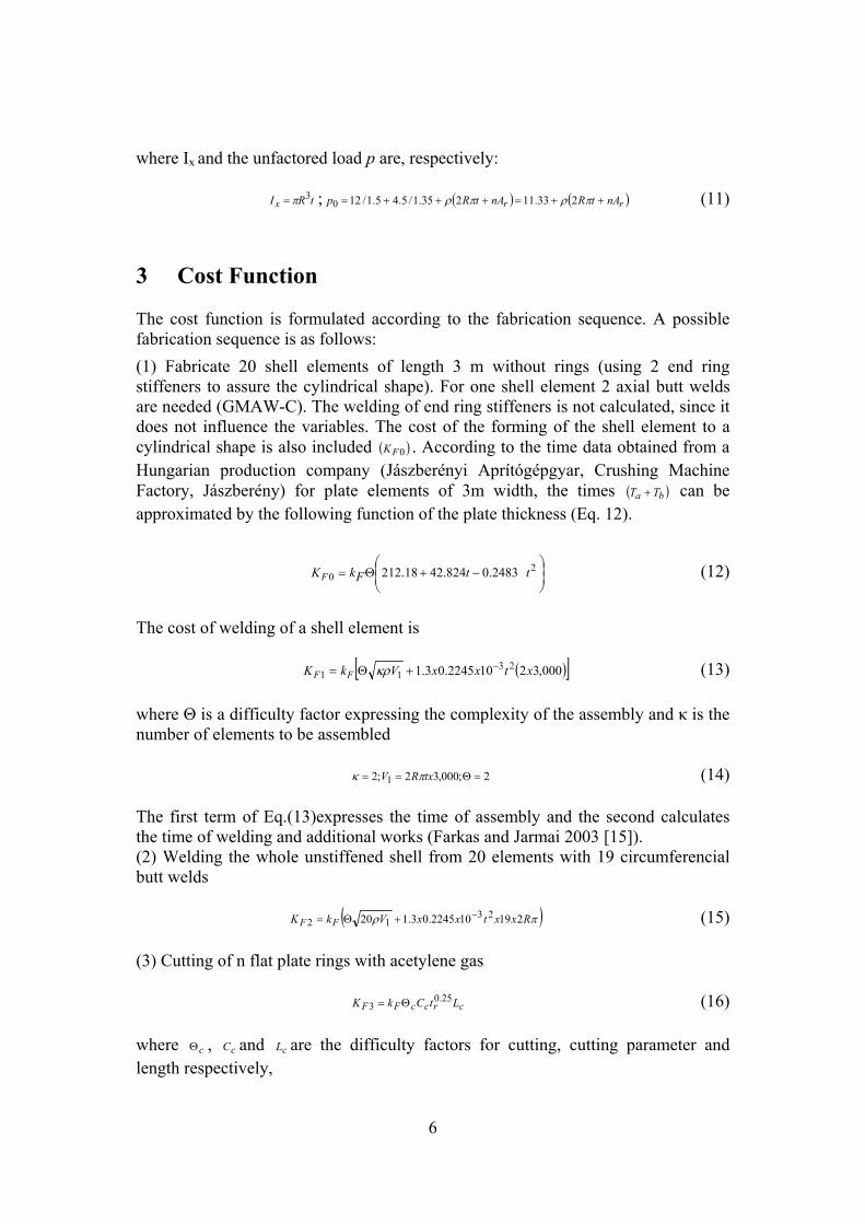
where Ix and the unfactored load p are, respectively:
tRIx3π= ; ( ) ( )rr nAtRnAtRp ++=+++= πρπρ 233.11235.1/5.45.1/120 (11)
3 Cost Function The cost function is formulated according to the fabrication sequence. A possible fabrication sequence is as follows: (1) Fabricate 20 shell elements of length 3 m without rings (using 2 end ring stiffeners to assure the cylindrical shape). For one shell element 2 axial butt welds are needed (GMAW-C). The welding of end ring stiffeners is not calculated, since it does not influence the variables. The cost of the forming of the shell element to a cylindrical shape is also included ( )0FK . According to the time data obtained from a Hungarian production company (Jászberényi Aprítógépgyar, Crushing Machine Factory, Jászberény) for plate elements of 3m width, the times ( )ba TT + can be approximated by the following function of the plate thickness (Eq. 12).
⎟⎟⎠
⎞⎜⎜⎝
⎛−+Θ= 2
0 2483.0824.4218.212 ttFkKF (12)
The cost of welding of a shell element is
( )[ ]000,32102245.03.1 2311 xtxxVkK FF
−+Θ= κρ (13) where Θ is a difficulty factor expressing the complexity of the assembly and κ is the number of elements to be assembled
2;000,32;2 1 =Θ== txRV πκ (14) The first term of Eq.(13)expresses the time of assembly and the second calculates the time of welding and additional works (Farkas and Jarmai 2003 [15]). (2) Welding the whole unstiffened shell from 20 elements with 19 circumferencial butt welds
( )πρ RxxtxxVkK FF 219102245.03.120 2312
−+Θ= (15) (3) Cutting of n flat plate rings with acetylene gas
crccFF LtCkK 25.03 Θ= (16)
where cΘ , cC and cL are the difficulty factors for cutting, cutting parameter and length respectively,

7
( )c c c rC x L R n R h n33, 1.1388 10 , 2 2 .π π−Θ = = ≈ + − (17) (4) Welding n rings into the shell with double-sided GMAW-C fillet welds. The number of fillet welds is 2n
( )( )nRxxxVnkK wFF παρ 4103394.03.11 2324
−++Θ= (18)
rw ta 5.0= , but mmaw 3min = .
nthhRVV rrr π⎟⎟⎠
⎞⎜⎜⎝
⎛−+=
2220 12 (19)
wa is taken so that the double fillet welded joint be equivalent to the stiffener
thickness. The total material cost is
2VkK MM ρ= (20) The total cost is
( ) 4321020 FFFFFM KKKKKKK +++++= (21) where .min/$1;/$1 == FM kkgk 4 Reliability-based optimization A failure event may be described by a functional relation, the limit state function, in the following way
F={g(x)≤0} (22) In the case the limit state function g (x) is a linear function of the normally distributed basic random variables x the probability of failure can be written in terms of the linear safety margin M as:
( ){ } ( )00 ≤=≤= MPxgPPF (23) which reduces to the evaluation of the standard normal distribution function
( )β−Φ=FP (24) where β is the reliability index given as
MM σμβ /= (25)
8
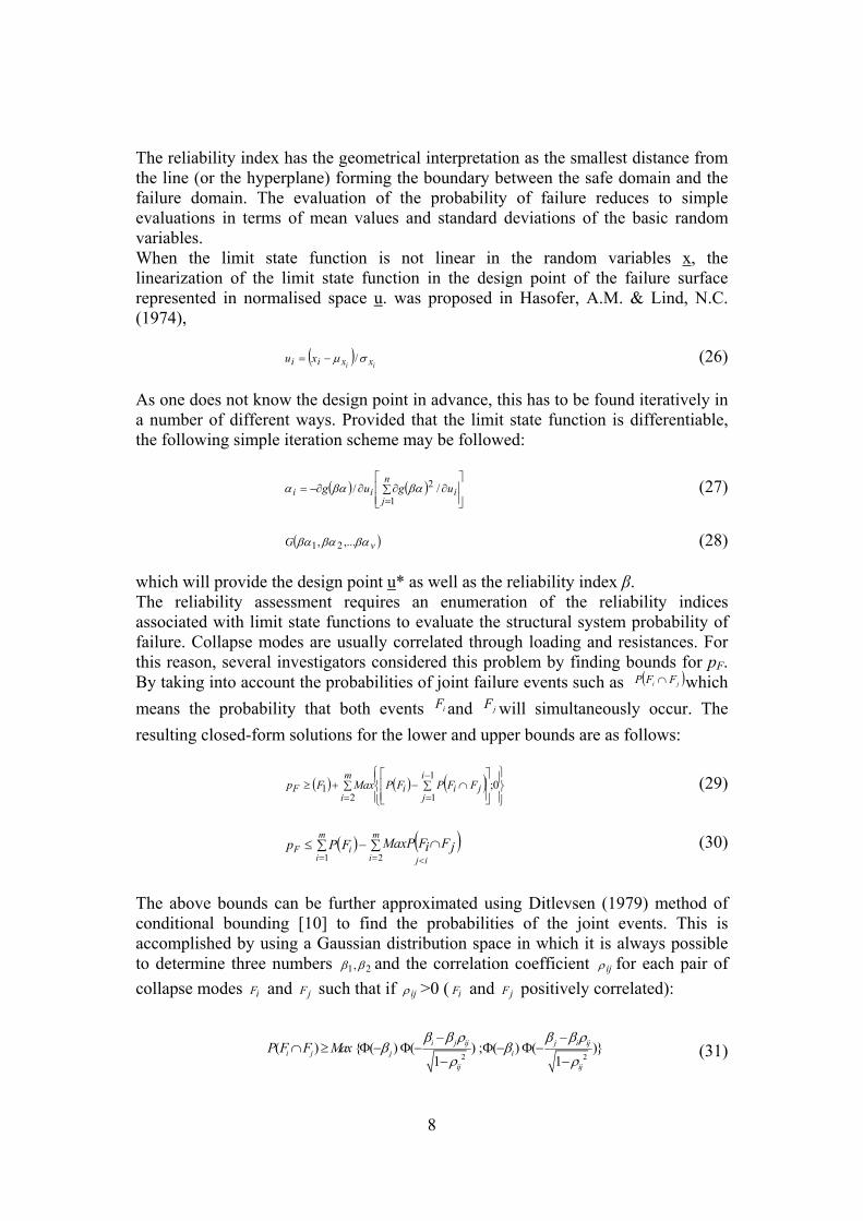
The reliability index has the geometrical interpretation as the smallest distance from the line (or the hyperplane) forming the boundary between the safe domain and the failure domain. The evaluation of the probability of failure reduces to simple evaluations in terms of mean values and standard deviations of the basic random variables. When the limit state function is not linear in the random variables x, the linearization of the limit state function in the design point of the failure surface represented in normalised space u. was proposed in Hasofer, A.M. & Lind, N.C. (1974),
( )ii xxii xu σμ /−= (26)
As one does not know the design point in advance, this has to be found iteratively in a number of different ways. Provided that the limit state function is differentiable, the following simple iteration scheme may be followed:
( ) ( )⎥⎥⎦
⎤
⎢⎢⎣
⎡∂∑∂∂−∂=
=i
n
jii ugug //
1
2βαβαα (27)
( )vG βαβαβα ,..., 21 (28)
which will provide the design point u* as well as the reliability index β. The reliability assessment requires an enumeration of the reliability indices associated with limit state functions to evaluate the structural system probability of failure. Collapse modes are usually correlated through loading and resistances. For this reason, several investigators considered this problem by finding bounds for pF. By taking into account the probabilities of joint failure events such as ( )ji FFP ∩ which means the probability that both events iF and jF will simultaneously occur. The resulting closed-form solutions for the lower and upper bounds are as follows:
( ) ( ) ( )⎪⎭
⎪⎬⎫
⎪⎩
⎪⎨⎧
⎥⎥⎦
⎤
⎢⎢⎣
⎡∑ ∩−∑+≥−
==0;
1
121
i
jjii
m
iF FFPFPMaxFp (29)
( ) ( )∑ ∑ ∩−≤
= = <
m
i
m
i ijiF jFiFMaxPFPp
1 2 (30)
The above bounds can be further approximated using Ditlevsen (1979) method of conditional bounding [10] to find the probabilities of the joint events. This is accomplished by using a Gaussian distribution space in which it is always possible to determine three numbers 21,ββ and the correlation coefficient ijρ for each pair of collapse modes iF and jF such that if ijρ >0 ( iF and jF positively correlated):
2 2( ) { ( ) ( ) ; ( ) ( )}
1 1i j ij j i ij
i j j i
ij ij
P F F Maxβ β ρ β β ρ
β βρ ρ
− −∩ ≥ Φ − Φ − Φ − Φ −
− − (31)

9
2 2( ) ( ) ( ) ( ) ( )
1 1i j ij j i ij
i j j i
ij ij
P F Fβ β ρ β βρ
β βρ ρ
− −∩ ≤Φ− Φ− +Φ− Φ−
− − (32)
In which βi and βj are the safety indices of the ith and the jth failure mode and Φ[ ] is the standardized normal probability distribution function. The probabilities of the joint events P(Fi∩Fj) in (29) and (30) are then approximated by the appropriate sides of (31) and (32). For example, if Fi and Fj are positively dependent for the lower (29) and upper (30) bounds it is necessary to use the approximations given by the upper (32) and lower (31) bounds, respectively. 5 Optimization Strategy 5.1 Branch and Bound The problem is non-linear and the design variables are discrete. Given the small number of discrete design variables an implicit branch and bound strategy was adopted to find the least cost solution. The two main ingredients are a combinatorial tree with appropriately defined nodes and some upper and lower bounds to the optimum solution associated the nodes of the tree. It is then possible to eliminate a large number of potential solutions without evaluating them. Three levels were considered in the combinatorial tree. The number of stiffeners n is fixed at the top of the tree, the remaining levels corresponding to the plate thickness t and the stiffener thickness tr (which is associated with the span length L). A strong branching rule was employed. Each node can be branched into new nodes. In the second level the branches correspond to the number of stiffeners used. At the third level the stiffener thickness and the associated span length is obtained, the resulting minimum discrete solution becomes the incumbent solution (upper bound). Any leaf of the tree whose bound is strictly less than the incumbent is active. Otherwise it is designated as terminated and need not to be considered further. The B&B tree is developed until every leaf is terminated. The branching strategy adopted was breadth first, consisting of choosing the node with the lower bound.
5.2 Optimum design with continuous design variables For solving each relaxed problem with continuous design variables the simultaneous minimization of the cost and constraints is sought. All these goals are cast in a normalized form. For the sake of simplicity, the goals and variables described in the following deal with stiffened shells. If a reference cost 0K is specified, this goal can be written in the form,
( ) ( )1 0, , , , / 1 0g t n h K t n h K= − ≤ (33)

10
Another two goals arise from the constraint on local shell buckling and panel buckling, respectively:
( )3 , , / 1 0c crg t n h σ σ= − ≤ (34)
( )2 , , / 1 0l acrg t n h σ σ= − ≤ (35) The remaining goal deals with deflection constraint:
( )4 max, / 1 0= − ≤g t h w w (36) The objective of this Pareto optimization is to obtain an unbiased improvement of the current design, which can be found by the unconstrained minimization of the convex scalar function Simões, L.M.C. and Templeman, A.B 1989, [13]:
( ) ( )( )⎥⎥⎦
⎤
⎢⎢⎣
⎡= ∑
=
3,exp1.1,
ljhtgnhtF ρ
ρ (37)
This form leads to a convex conservative approximation of the objective and constraint boundaries. Accuracy increases with ρ. The strategy adopted was an iterative sequence of explicit approximation models, formulated by taking Taylor series approximations of all the goals truncated after the linear term. This gives:
Min F ( ) ( ) ( ) ( )⎥⎥⎦
⎤
⎢⎢⎣
⎡
⎟⎟⎠
⎞⎜⎜⎝
⎛
∂
∂+
∂
∂+= ∑
=
3 000
,,,exp1.1,
lj
jj dhh
htgdt
thtg
htgnht ρρ
(38)
This problem has an analytic solution giving the design variables changes dt and dh . Solving for a particular numerical value of ojg forms an iteration of the solution to problem (38). Move limits must be imposed on the design variable changes to guarantee the accuracy of the approximations. Given the small number of design variables an analytic solution is available. During the iterations the control parameter ρ, which should not be decreased to produce an improved solution, is increased. 6 Optimum Designs and Discussion The optimum solutions as a function of the length by using level I procedures (safety loading and resistance factors) are given in Table 1:

11
t n ts Maximum Span Length L (m) Cost Cost/Span
4 6 12 29 44674 1.540
5 6 13 35 53361 1.524
5 6 14 41 53904 1.314
5 6 15 43 54485 1.267
6 6 17 50 64408 1.288
6 6 18 56 64779 1.156
6 7 17 57 65248 1.144
7 7 19 61 75390 1.236
7 7 20 68 76250 1.121
7 8 19 69 76795 1.113
8 9 20 72 87993 1.222
Table 1. Deterministic solutions
t n ts Maximum Span Length L (m) pf
4 6 12 29 10-4
5 6 13 35 ≤ 10-5
5 6 14 41 10-5
5 6 15 43 10-4
6 6 17 50 ≤ 10-5
6 6 18 56 10-4
6 7 17 57 10-4
7 7 19 61 ≤ 10-5
7 7 20 68 10-5
7 8 19 69 10-4
8 9 20 72 10-4
Table 2. Reliability-based solutions
The local shell buckling is in general the most important constraint for the lower span optimum solution (L=29m). For intermediate spans the panel ring buckling is often decisive. The deflection constraint is relevant for longer spans. Both to

12
increase the number of rings (and reduce tr) and the opposite are associated with more expensive solutions. The material cost is about half of total cost. The forming cost of the shell elements is significant. The most cost effective spans (lower cost/span ratios) range from 56 to 69 m. The partial safety factors were calibrated to introduce randomness. Coefficients of variance of 0.20 for the live loading and 0.05 for the yield stress were adopted leading to adequate mean loading and yield stress. A high mode correlation was observed considering both failure modes (local shell buckling and maximum deflection). The reliability-based solutions are the same as the deterministic if a pf = 10-4 is required. However if a pf =10-5 is imposed the optimum solutions found for the span lengths 29, 43, 56, 57, 69 and 72 m are no longer valid. The higher reliability requirement would lead to a thicker shell (an increase of t). The remaining optimum solutions are indifferent to the specified pf, because the most important constraint is the panel ring buckling and this requirement is deterministic. References [1] European Convention of Constructional Steelwork (ECCS) Recommendations
for Steel Construction, Buckling of steel shells. No. 56, Brussels, 1988. [2] American Petroleum Institute (API) Bulletin 2U, Bulletin on stability design
of cylindrical shells, 2nd ed. Washington, 2000. [3] Det Norske Veritas (DNV), Buckling strength analysis, Classification Notes.
No. 30.1, Hovik, Norway, 1995. [4] Farkas,J.,Jármai,K.,Virág,Z., “Optimum design of a belt-conveyor bridge
constructed as a welded ring-stiffened cylindrical shell“, Welding in the World, Pergamon Press, 48(1-2), 37-41, 2004.
[5] Harding, J.E., “Ring-stiffened cylinders under axial and external pressure loading“, Proc. Inst. Civ. Engrs, Part 2, 71, 863-878, 1981.
[6] Dowling, P.J., Harding, J.E., “Research in Great Britain on the stability of circular tubes”, Proc. 3rd Int. Conference Behaviour of Offshore Structures, Vol. 2, Hemisphere Publ. Corp- McGraw Hill, New York", 59-73, 1982.
[7] Ellinas, C.P., Supple, W.J., Walker, A.C., Buckling of Offshore Structures, Granada, London, 1984.
[8] Frieze, P .A., Chao S., Faulkner, D., “Strength of ring-stiffened cylinders under combined loads“, Proc. 16th Annual Offshore Technology Conference, Vol. 2, Paper OTC 4714, 39-48, 1984.
[9] Shen Hui-shen, Zhou Pin, Chen Tien-yun, “Postbuckling analysis of stiffened cylindrical shells under combined external pressure and axial compression“, Thin-Walled Struct, 15, 43-63, 1993.
[10] Tian, J., Wang, C.M., Swaddiwudhipong, S., “Elastic buckling analysis of ring-stiffened cylindrical shells under general pressure loading via the Ritz method“, Thin-Walled Struct, 35,1-24, 1999.
[11] A.M. Hasofer and N.C. Lind, “Exact and invariant second moment code format“, J.Eng. Mech Div. 100 (1), 111-121, 1974.
[12] O. Ditlevsen, “Narrow reliability bounds for structural systems“, J.Struct. Mech, 7 (4), 453-472, 1979.

13
[13] L.M.C. Simões and A.B. Templeman, “Entropy-based synthesis of pretensioned cable net structures“, Engineering Optimization, , 15, 121-140, 1989.
[14] Farkas J., “Thickness design of axially compressed unstiffened cylindrical shells with circumferential welds”, Welding in the World, 46(11/12), 26-29 2002.
[15] Farkas, J., Jarmai, K., Economic design of metal structures. Millpress Science Publisher, Rotterdam, 2003.


