Embed Size (px)
Citation preview
MRMap Development Team 14/01/2009
MRMap - www.mrmap.org.uk
MRMap-GPS-Tracking-Communications-Safety-Mountain Rescue-Mapping-Downloads-Free Software
Rebroadcast Manual
Simoco SRM9000-Based Radio Rebroadcast & Repeater Devices.
Collated By The LDSAMRA Communications Sub Committee
On behalf of the contributing teams of the North West of England and Southern Scotland.
Rev C 14 January 2009
MRMap Development Team 14/01/2009
As a result of a meeting held at Keswick MRT HQ on 6th September 2005, this document has been produced in order that information presented at the meeting but considered too detailed for inclusion in the minutes, might be passed on to all interested parties. It is not pitched at any presumed level of understanding and some things are explained even though they may be obvious to all. Conversely, anything that’s not obvious can be ex-plained in greater detail, by one or more of the contributors. The sections included have come from the team responsible for developing the device or con-cept and the author is responsible only for graphics and writing up or collation of the various documents. All re-broadcast devices are based upon current Simoco radio equipment and thanks are due to Team Simoco Ltd in Derby and Huntingdon, and TMC Radio Pty Ltd in Australia for their help in resolving issues that arose during the construction of these devices.
In the majority of cases, the wiring associated with power supply, speakers and aerial connec-tions are not shown in order to help with clarity. In the case of speakers, this is a local deci-sion as to whether they are used. They are not strictly necessary to the functioning of a re-broadcast or repeater device but one will be required if the ‘Standard’ variation is adopted as one of the radios forms the normal comms set for the vehicle when it’s not in re-broadcast mode.
With thanks to :- Bowland Pennine MRT Coniston MRT Duddon & Furness MRT Kendal MRT Keswick MRT Moffatt MRT Penrith MRT Roger Taylor, Tower Communications Team Simoco Ltd TMC Radio Pty Ltd Tom Taylor ARCC Kinloss
MRMap Development Team 14/01/2009
Introduction:-
The concept of re-broadcasting:- The devices to be described are intended to act as two-way signal enhancement units to enable radio communications into difficult-to-reach areas. To this end, a system using two simplex transmissions on different frequencies has been adopted where the Base or Incident Command Post (ICP) transmits and receives on one channel and the Hill-Parties do likewise on their Team Working Channel (TWC). From this it can be seen that operation at the Hill-Party end remains simplex for normal comms on the hill. Hand-portables can still speak to each other whilst taking advantage of the increased area or distance coverage provided by the re-broadcast device. The device itself is nominally mounted in a vehicle that is dynamically positioned to allow for the translation of the Base transmission onto the frequency used by the Hill-Party and vice versa. When using the re-broadcast unit, Base cannot speak directly to the Hill-Party radios. It must go via the re-broadcast device hence the positioning of this vehicle is critical to operation of the system as a whole. Having said that, it is strongly recommended that Bases / ICPs do monitor the TWC as it is then often possible to make direct contact with a party that is not in the cover-age area of the rebroadcast unit. As originally agreed in negotiations with OfCom for permission to use such a device, it must be clearly stated from the outset that permanent operation of re-broadcast transmitters was not agreed by the authorities. Re-broadcast should be used to alleviate individual communications problems on a case-by-case basis. When normal methods of communications fail. That is, when direct communications between the Base/ICP and the deployed Hill-Party hand-portable radios is not directly possible due to the nature of the immediate terrain and not the terrain in general. More rebroadcast channels have been requested so that if the topography of any Team’s area forces continuous use of a re-transmission system then they may deploy a unit on a more per-manent basis. At the time of update August 2008, no additional link channels have been author-ised.
We are, however, now authorised for operation of re-broadcast devices from perma-
nent locations.
It is important that this is fully understood by any Team wishing to use re-broadcast as there are almost certainly going to be incidences of mutual interference between different Teams during the initial testing phase and, indeed, in their normal operational usage. Any team operating out-side the conditions of use of re-broadcast devices has no redress if it receives an unacceptable level of interference. Conversely, any team causing interference to others may well find OfCom on their doorstep. Always bear in mind that the new ‘MR’ channels are subject to the same level of official monitoring that is applied to the rest of the marine band.
Rob Brookes/Tom Taylor 14 January 2009
MRMap Development Team 14/01/2009
The General Principles of Rebroadcasting As you will see in the following pages, re-broadcast is not a lot different in effect, from manual relay. The same vehicle in the same position could handle both methods. The only real difference is that there is now no need for the vehicle driver to relay massages to base. The argument that manual relay takes a team member off the hill is not really valid as most if not all teams have people who’s hill-going days are a memory rather than a fact. These people do, however, have a wealth of understanding as to what the rest are doing when dashing up the hill. They are to be found in the manual relay vehicles of a number of teams already. Radio re-broadcast does not make them redundant, in fact it may well make their lives a little more interesting occasionally. For automatic re-broadcast to work, the vehicle must be correctly positioned. The driver of the manual relay vehicle may well, during the course of a search for example, have to move the vehicle in order to maintain good comms between him or herself and base whilst still being able to contact the moving hill-party. This doesn’t change in re-broadcast and if there is any possibility of the hill-party shifting it’s position then an un-manned re-bro vehicle may become unusable. Intelligent autonomy is required from your rebro vehicle driver, they must re-locate to a new position, sometimes without any instruction from base. They become a very important element of your communications system as a whole. The job of the rebro vehicle driver, is to find the best position to establish good comms be-tween base and the vehicle and the hill-party and the vehicle. Once this has been done, the re-broadcast device can be switched on and comms is then automatically handled by the vehicle. However, the driver still needs to monitor the comms to ensure that the vehicle is still in the optimum position. If not then he or she will have to advise both parties of an intention to re-locate and this must be done as quickly as possible. Re-broadcast isn’t magic, it won’t always work. All teams have places where comms are par-ticularly bad and base will expect to loose the hill-party in such locations. If they’re just passing through this location, it probably doesn’t matter. If the casualty has managed to crawl to the most difficult location possible before collapsing then most of your work will occur out of reach of comms with base. Whether this is important or not depends on a lot of factors but it proba-bly will be. This is what the re-broadcast system was designed for as against wide area repeaters de-signed to provide saturation coverage of a team area. Most Lakes and Lancs teams already have reasonable coverage of their areas by radio, usually from existing fixed sites. We have all had radios for over fifteen years so they aught to work by now! They don’t cover everywhere, indeed, the laws of physics prevent this anyway. However, the positioning of remote aerials or careful positioning of bases has resulted in generally good coverage. In effect, most teams unknowingly have a simplex version of ‘Wide-area-coverage’ already.
MRMap Development Team 14/01/2009
What re-broadcast does is to fill in the gaps on those occasions when the main system struggles to cope. You wheel it out in just the same way you would your manual relay vehicle. Under some circumstances, it doesn’t even have to be a full-blown team vehicle anyway. These devices can be fitted to virtually anything that can provide them with power as Penrith and Bowland Pennine have both shown. Now we have it where the re-bro vehicle is not taking out an active hill-going member of the team, nor is it necessarily tying up a team vehicle. If the private vehicle doesn’t have a pump-up mast fitted, and how many do? Arrange with a local farmer who lives at a well-used relay location, to put a mast on his barn and plug your radios into it when you need them. There are always ways. The job of the vehicle driver now becomes more critical as base can quite easily tell when a hill-party are moving out of comms range but they will find it hard to predict just where the relay vehicle needs to move to. That’s a job best left to the man on the ground, the driver. Relay vehicle driver is a job probably not best left to the newest team member. If the driver uses a handset that has been arranged to scan between the team working channel and the rebro channel, then he or she will be able to hear both sides of the conversation, provided by the rebro they’re operating. By the same token, the driver can also speak to either side of the rebro by using the opposite channel on the handset. They can become either base or hill-party depending on which it is they need to speak to. Indeed, program the two channels to say who it is you will be speaking to and it’s even easier. Program the radio’s display to read ‘Hill-Party’ and program the frequency as 147.350 MHz and the driver will become base for the time being. The transmissions will be boosted by the re-bro. If this is used then the handset’s power need only be a watt or less and the battery will last forever. By the same token, program the display to say ‘Base’ and the channel as your TWC and the driver becomes another hill-party radio and will be heard by base via the re-bro. In neither case does the driver’s radio need to be able to transmit back to either side un-aided. It uses the re-bro in just the same way all others do. The driver can now leave the vehicle temporarily without being out of comms with either hill or base. Sometimes the urgency of a message can be lost when it’s passed by another’s voice. Using re-broadcast, the margin for translation errors when passing messages is dramatically reduced as no intermediary has to repeat them with all the inherent dangers of accidental interpretation or inflection changes. The intention isn’t that they are used routinely to provide base to hill communications although the position of your team base has a lot to do with this and, for example, Duddon & Furness have a base location not well suited to covering their whole area. Their deployment of re-broadcast vehicles will be more than most. It’s not in the interests of avoiding interference for us all to operate in this way but one or two aren’t going to cause too many problems if those who don’t need to deploy them regularly, keep to that principle.
1
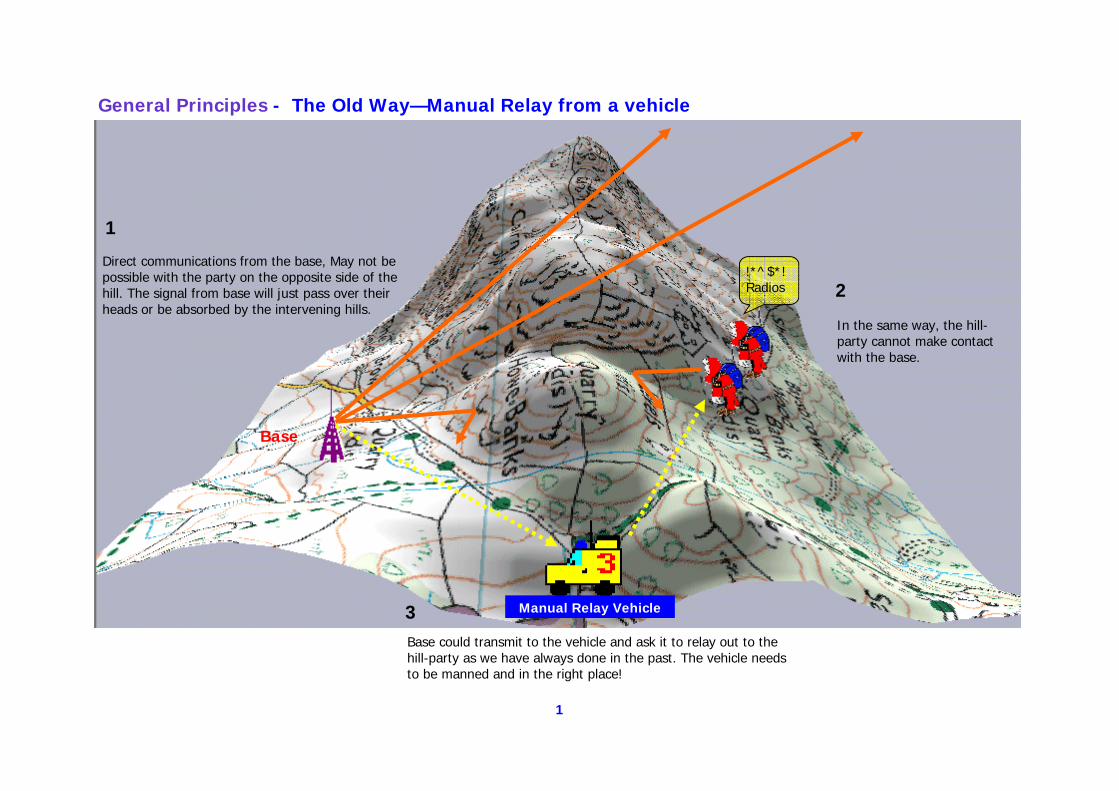
Direct communications from the base, May not be possible with the party on the opposite side of the hill. The signal from base will just pass over their heads or be absorbed by the intervening hills.
In the same way, the hill-party cannot make contact with the base.
Base could transmit to the vehicle and ask it to relay out to the hill-party as we have always done in the past. The vehicle needs to be manned and in the right place!
General Principles - The Old Way—Manual Relay from a vehicle
Manual Relay Vehicle
!*^$*! Radios
Base
1
2
3
2
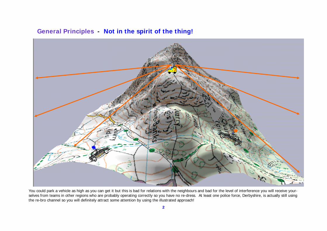
You could park a vehicle as high as you can get it but this is bad for relations with the neighbours and bad for the level of interference you will receive your-selves from teams in other regions who are probably operating correctly so you have no re-dress. At least one police force, Derbyshire, is actually still using the re-bro channel so you will definitely attract some attention by using the illustrated approach!
General Principles - Not in the spirit of the thing!
3
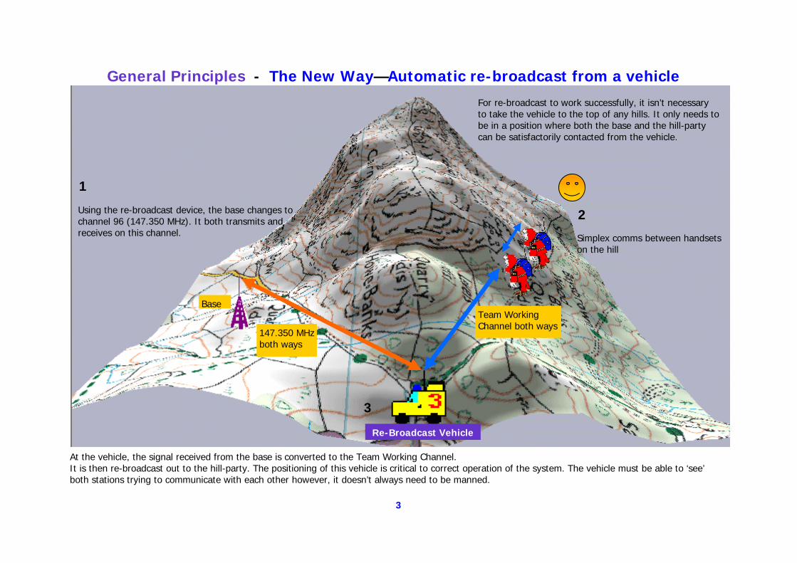
Using the re-broadcast device, the base changes to channel 96 (147.350 MHz). It both transmits and receives on this channel.
At the vehicle, the signal received from the base is converted to the Team Working Channel. It is then re-broadcast out to the hill-party. The positioning of this vehicle is critical to correct operation of the system. The vehicle must be able to ‘see’ both stations trying to communicate with each other however, it doesn’t always need to be manned.
147.350 MHz both ways
Team Working Channel both ways
For re-broadcast to work successfully, it isn’t necessary to take the vehicle to the top of any hills. It only needs to be in a position where both the base and the hill-party can be satisfactorily contacted from the vehicle.
Simplex comms between handsets on the hill
Re-Broadcast Vehicle
General Principles - The New Way—Automatic re-broadcast from a vehicle
Base
1
2
3
4
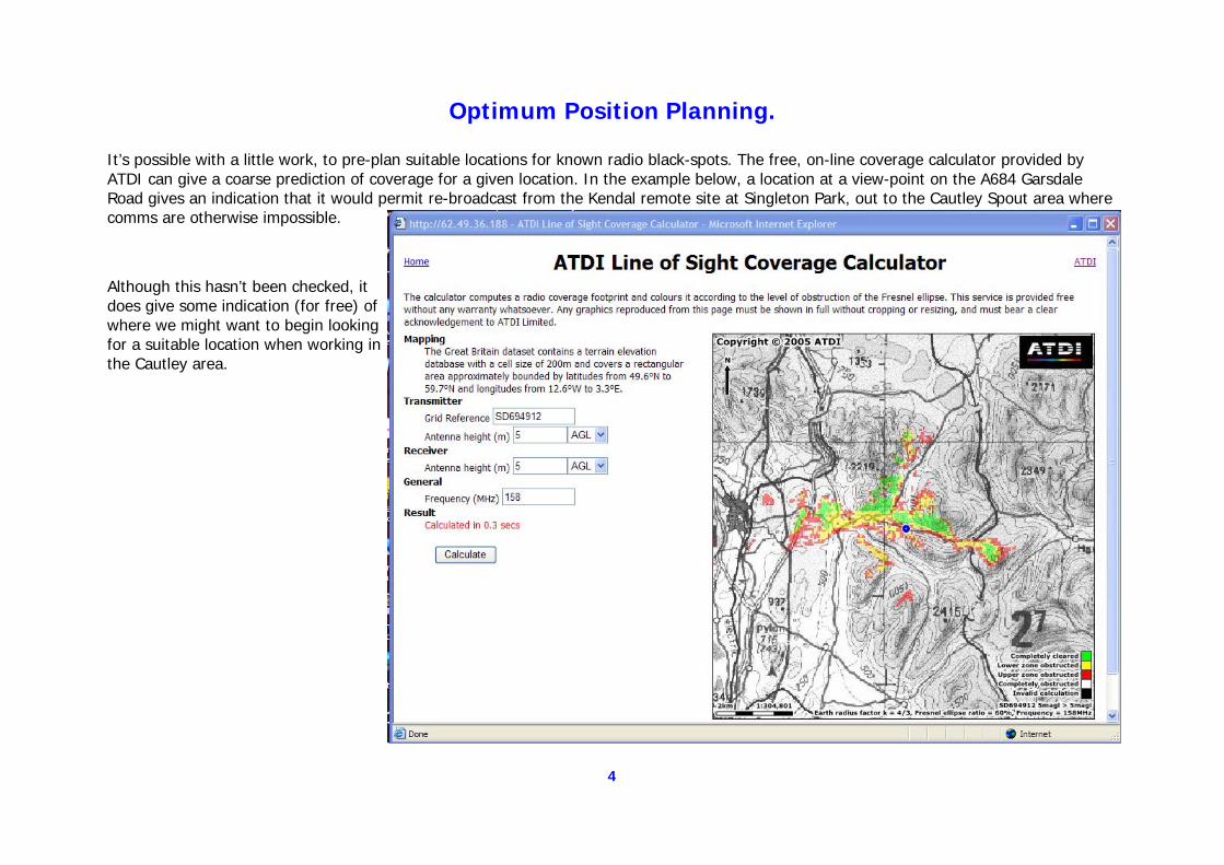
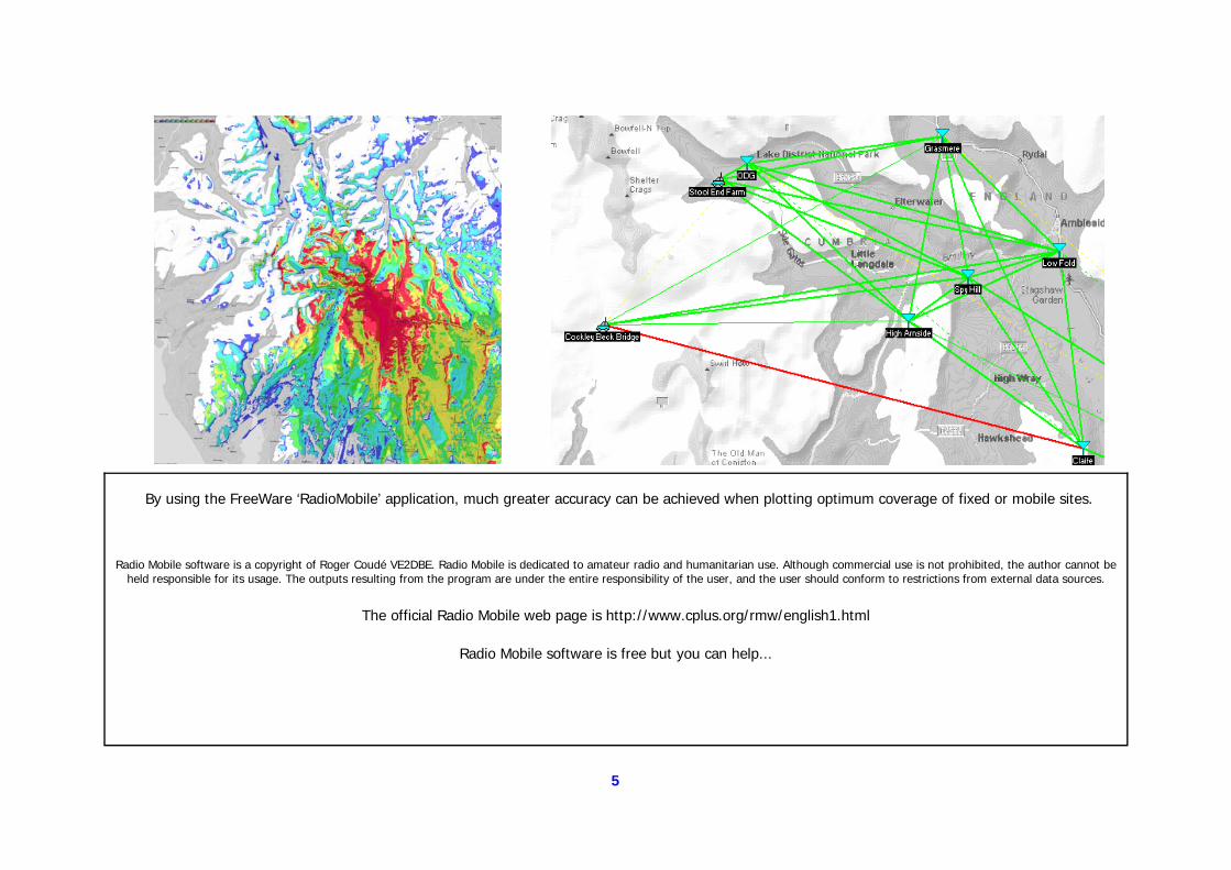
Optimum Position Planning. It’s possible with a little work, to pre-plan suitable locations for known radio black-spots. The free, on-line coverage calculator provided by ATDI can give a coarse prediction of coverage for a given location. In the example below, a location at a view-point on the A684 Garsdale Road gives an indication that it would permit re-broadcast from the Kendal remote site at Singleton Park, out to the Cautley Spout area where comms are otherwise impossible.
Although this hasn’t been checked, it does give some indication (for free) of where we might want to begin looking for a suitable location when working in the Cautley area.
5
Radio Mobile software is a copyright of Roger Coudé VE2DBE. Radio Mobile is dedicated to amateur radio and humanitarian use. Although commercial use is not prohibited, the author cannot be held responsible for its usage. The outputs resulting from the program are under the entire responsibility of the user, and the user should conform to restrictions from external data sources.
The official Radio Mobile web page is http://www.cplus.org/rmw/english1.html
Radio Mobile software is free but you can help...
By using the FreeWare ‘RadioMobile’ application, much greater accuracy can be achieved when plotting optimum coverage of fixed or mobile sites.
6
First Steps - The Simple Approach to Rebroadcasting.
The following information is based upon documentation published on the TMC Radio website and research carried out by various teams.
It represents variations on broadly similar systems that increase in complexity as they go on. Ideally a team radio officer would select the version he or she feels is most appropriate for their own team. All the following examples work but there are explained reasons why some of the
very simple versions would not be completely practical.
7
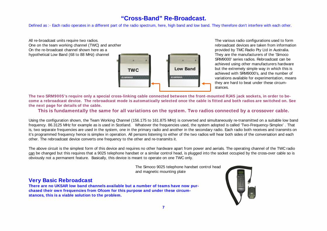
The various radio configurations used to form rebroadcast devices are taken from information provided by TMC Radio Pty Ltd in Australia. They are the manufacturers of the ‘Simoco SRM9000’ series radios. Rebroadcast can be achieved using other manufacturers hardware but the extremely simple way in which this is achieved with SRM9000’s, and the number of variations available for experimentation, means they are hard to beat under these circum-stances.
All re-broadcast units require two radios. One on the team working channel (TWC) and another On the re-broadcast channel shown here as a hypothetical Low Band (68 to 88 MHz) channel
TWC Low Band
The two SRM9005’s require only a special cross-linking cable connected between the front-mounted RJ45 jack sockets, in order to be-come a rebroadcast device. The rebroadcast mode is automatically selected once the cable is fitted and both radios are switched on. See the next page for details of the cable.
This is fundamentally the same for all variations on the system. Two radios connected by a crossover cable.
Using the configuration shown, the Team Working Channel (156.175 to 161.875 MHz) is converted and simultaneously re-transmitted on a suitable low band frequency. 86.3125 MHz for example as is used in Scotland. Whatever the frequencies used, the system adopted is called ‘Two-Frequency-Simplex’ . That is, two separate frequencies are used in the system, one in the primary radio and another in the secondary radio. Each radio both receives and transmits on it’s programmed frequency hence is simplex in operation. All persons listening to either of the two radios will hear both sides of the conversation and each other. The rebroadcast device converts one frequency to the other and re-transmits it. The above circuit is the simplest form of this device and requires no other hardware apart from power and aerials. The operating channel of the TWC radio can be changed but this requires that a 9025 telephone handset or a similar control head, is plugged into the socket occupied by the cross-over cable so is obviously not a permanent feature. Basically, this device is meant to operate on one TWC only.
The Simoco 9025 telephone handset control head and magnetic mounting plate
Very Basic Rebroadcast There are no UKSAR low band channels available but a number of teams have now pur-chased their own frequencies from Ofcom for this purpose and under these circum-stances, this is a viable solution to the problem.
“Cross-Band” Re-Broadcast. Defined as :- Each radio operates in a different part of the radio spectrum, here, high band and low band. They therefore don’t interfere with each other.
8
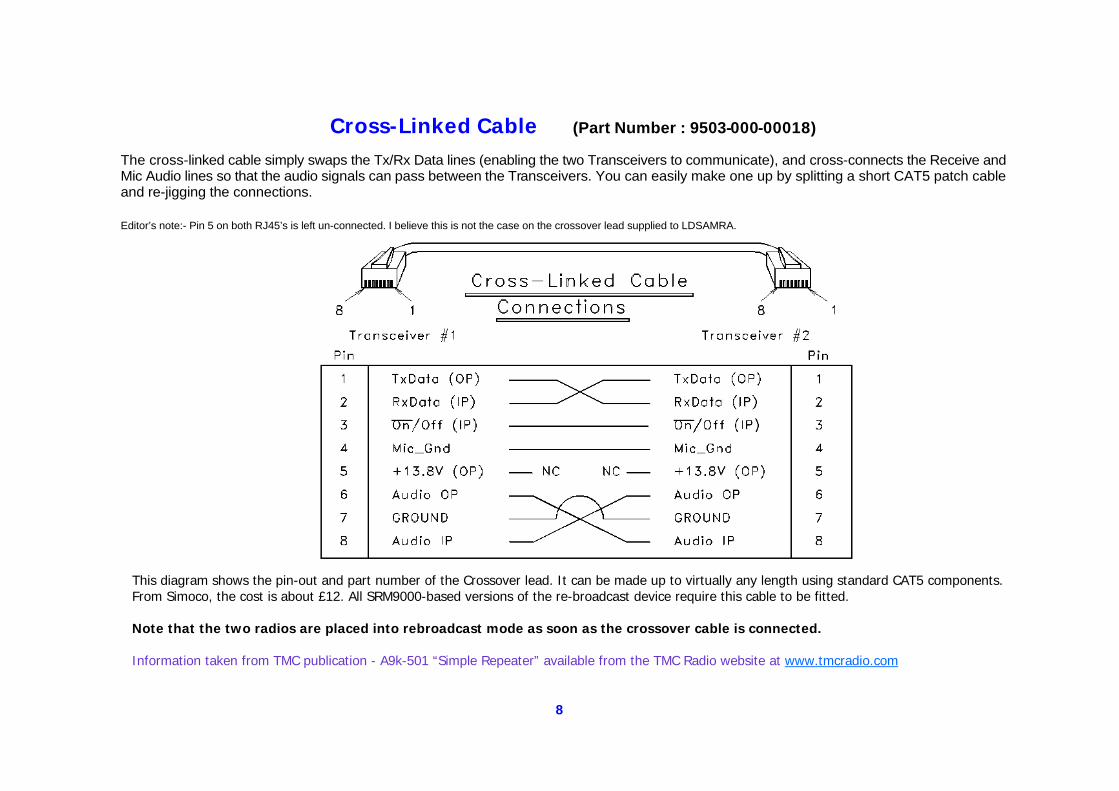
Cross-Linked Cable (Part Number : 9503-000-00018) The cross-linked cable simply swaps the Tx/Rx Data lines (enabling the two Transceivers to communicate), and cross-connects the Receive and Mic Audio lines so that the audio signals can pass between the Transceivers. You can easily make one up by splitting a short CAT5 patch cable and re-jigging the connections. Editor’s note:- Pin 5 on both RJ45’s is left un-connected. I believe this is not the case on the crossover lead supplied to LDSAMRA.
This diagram shows the pin-out and part number of the Crossover lead. It can be made up to virtually any length using standard CAT5 components. From Simoco, the cost is about £12. All SRM9000-based versions of the re-broadcast device require this cable to be fitted. Note that the two radios are placed into rebroadcast mode as soon as the crossover cable is connected. Information taken from TMC publication - A9k-501 “Simple Repeater” available from the TMC Radio website at www.tmcradio.com
9
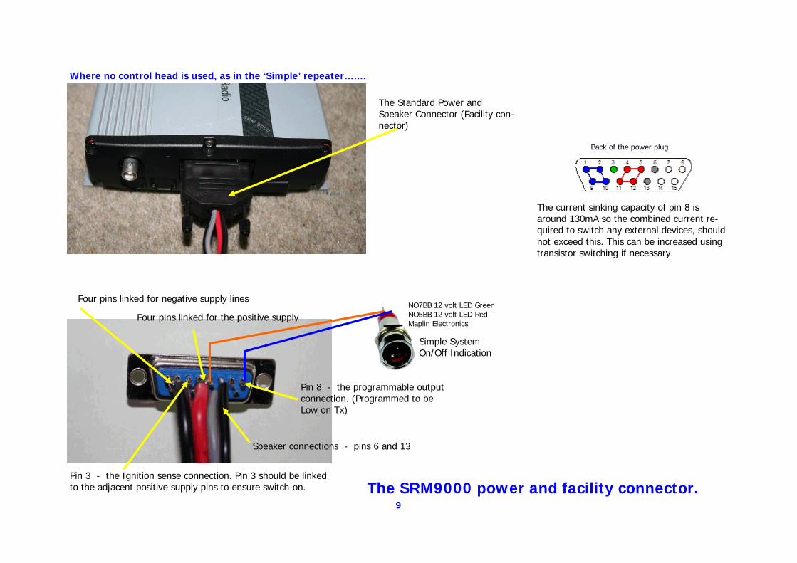
The current sinking capacity of pin 8 is around 130mA so the combined current re-quired to switch any external devices, should not exceed this. This can be increased using transistor switching if necessary.
Back of the power plug
The Standard Power and Speaker Connector (Facility con-nector)
Four pins linked for negative supply lines
Four pins linked for the positive supply
Pin 3 - the Ignition sense connection. Pin 3 should be linked to the adjacent positive supply pins to ensure switch-on.
Pin 8 - the programmable output connection. (Programmed to be Low on Tx)
The SRM9000 power and facility connector.
Speaker connections - pins 6 and 13
NO7BB 12 volt LED Green NO5BB 12 volt LED Red Maplin Electronics
Simple System On/Off Indication
Where no control head is used, as in the ‘Simple’ repeater…….
10
The TMC Radio ‘Simple’ Repeater
This is the simplest form of rebroadcast/repeater possible using Simoco SRM9005 radios. Normally no speakers would be connected and there is no control head.
Because both radios operate on frequencies that are not too far apart, some interference between the two is to be expected. Adequate vertical separation of the antenna can help here.
Horizontal aerial separation is unlikely to prove effective unless your base is in the grounds of a medium size castle.
You are recommended to visit the TMC Radio website and to download the file A9k-501 ‘Simple Repeater’. www.tmcradio.com
11
TWC 147.350 MHz
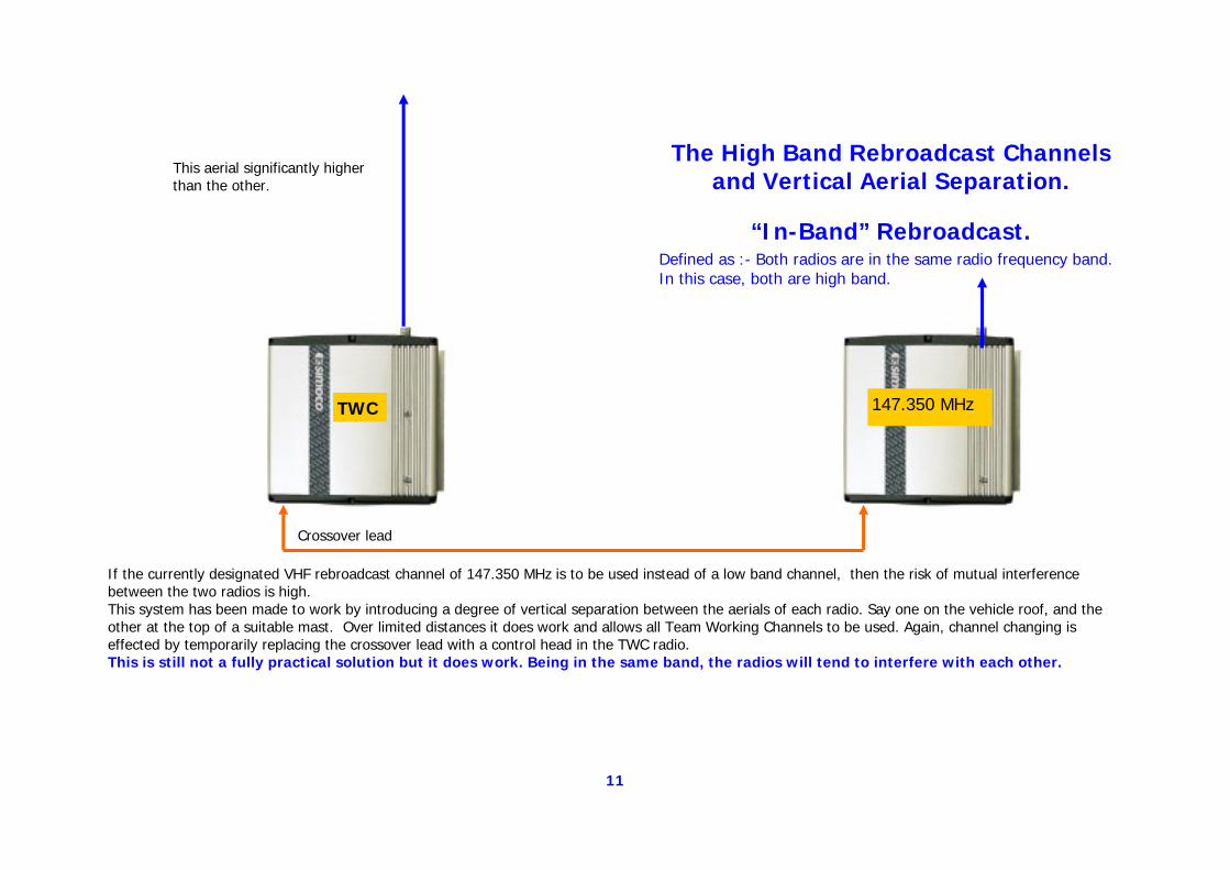
If the currently designated VHF rebroadcast channel of 147.350 MHz is to be used instead of a low band channel, then the risk of mutual interference between the two radios is high. This system has been made to work by introducing a degree of vertical separation between the aerials of each radio. Say one on the vehicle roof, and the other at the top of a suitable mast. Over limited distances it does work and allows all Team Working Channels to be used. Again, channel changing is effected by temporarily replacing the crossover lead with a control head in the TWC radio. This is still not a fully practical solution but it does work. Being in the same band, the radios will tend to interfere with each other.
This aerial significantly higher than the other.
Crossover lead
The High Band Rebroadcast Channels and Vertical Aerial Separation.
“In-Band” Rebroadcast. Defined as :- Both radios are in the same radio frequency band. In this case, both are high band.
12
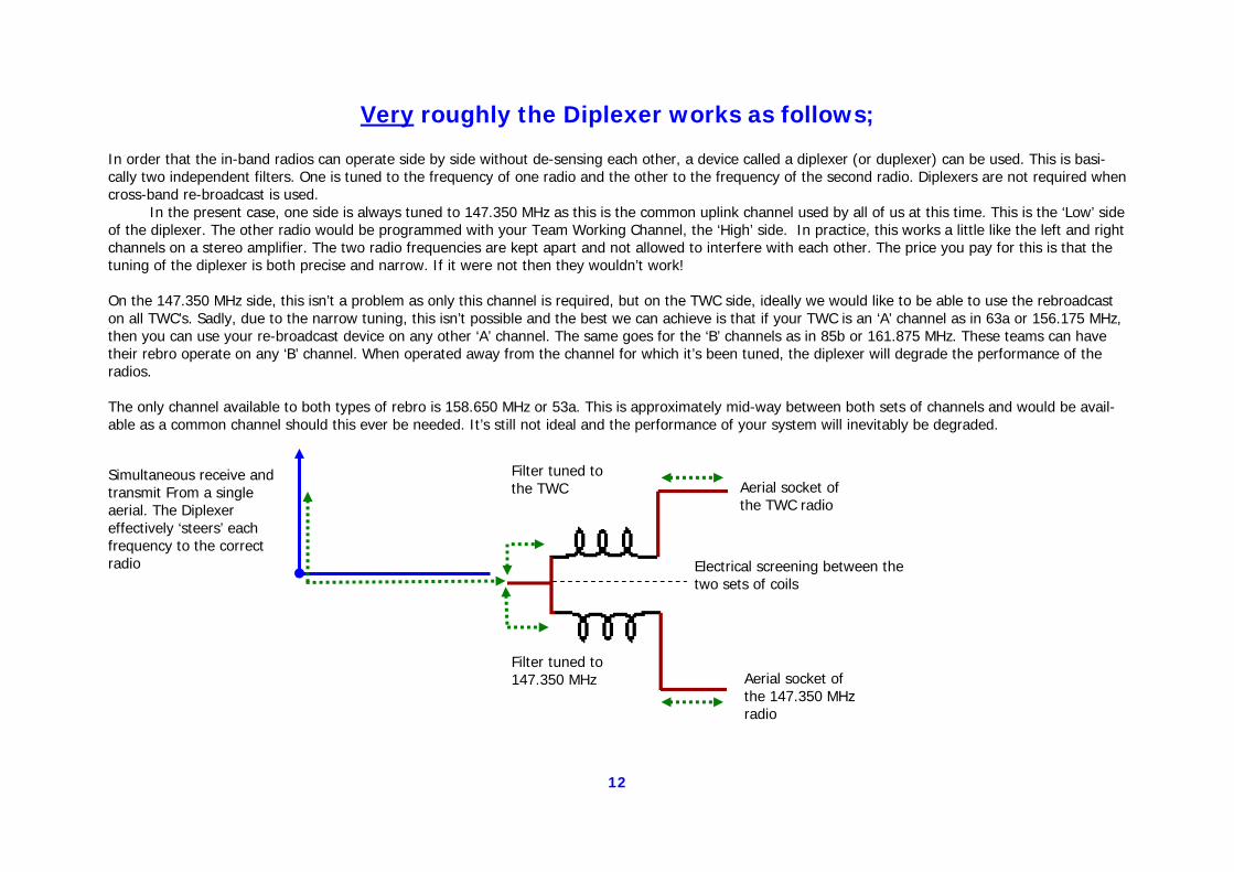
Very roughly the Diplexer works as follows; In order that the in-band radios can operate side by side without de-sensing each other, a device called a diplexer (or duplexer) can be used. This is basi-cally two independent filters. One is tuned to the frequency of one radio and the other to the frequency of the second radio. Diplexers are not required when cross-band re-broadcast is used. In the present case, one side is always tuned to 147.350 MHz as this is the common uplink channel used by all of us at this time. This is the ‘Low’ side of the diplexer. The other radio would be programmed with your Team Working Channel, the ‘High’ side. In practice, this works a little like the left and right channels on a stereo amplifier. The two radio frequencies are kept apart and not allowed to interfere with each other. The price you pay for this is that the tuning of the diplexer is both precise and narrow. If it were not then they wouldn’t work! On the 147.350 MHz side, this isn’t a problem as only this channel is required, but on the TWC side, ideally we would like to be able to use the rebroadcast on all TWC’s. Sadly, due to the narrow tuning, this isn’t possible and the best we can achieve is that if your TWC is an ‘A’ channel as in 63a or 156.175 MHz, then you can use your re-broadcast device on any other ‘A’ channel. The same goes for the ‘B’ channels as in 85b or 161.875 MHz. These teams can have their rebro operate on any ‘B’ channel. When operated away from the channel for which it’s been tuned, the diplexer will degrade the performance of the radios. The only channel available to both types of rebro is 158.650 MHz or 53a. This is approximately mid-way between both sets of channels and would be avail-able as a common channel should this ever be needed. It’s still not ideal and the performance of your system will inevitably be degraded.
Simultaneous receive and transmit From a single aerial. The Diplexer effectively ‘steers’ each frequency to the correct radio
Filter tuned to the TWC Aerial socket of
the TWC radio
Filter tuned to 147.350 MHz Aerial socket of
the 147.350 MHz radio
Electrical screening between the two sets of coils
13
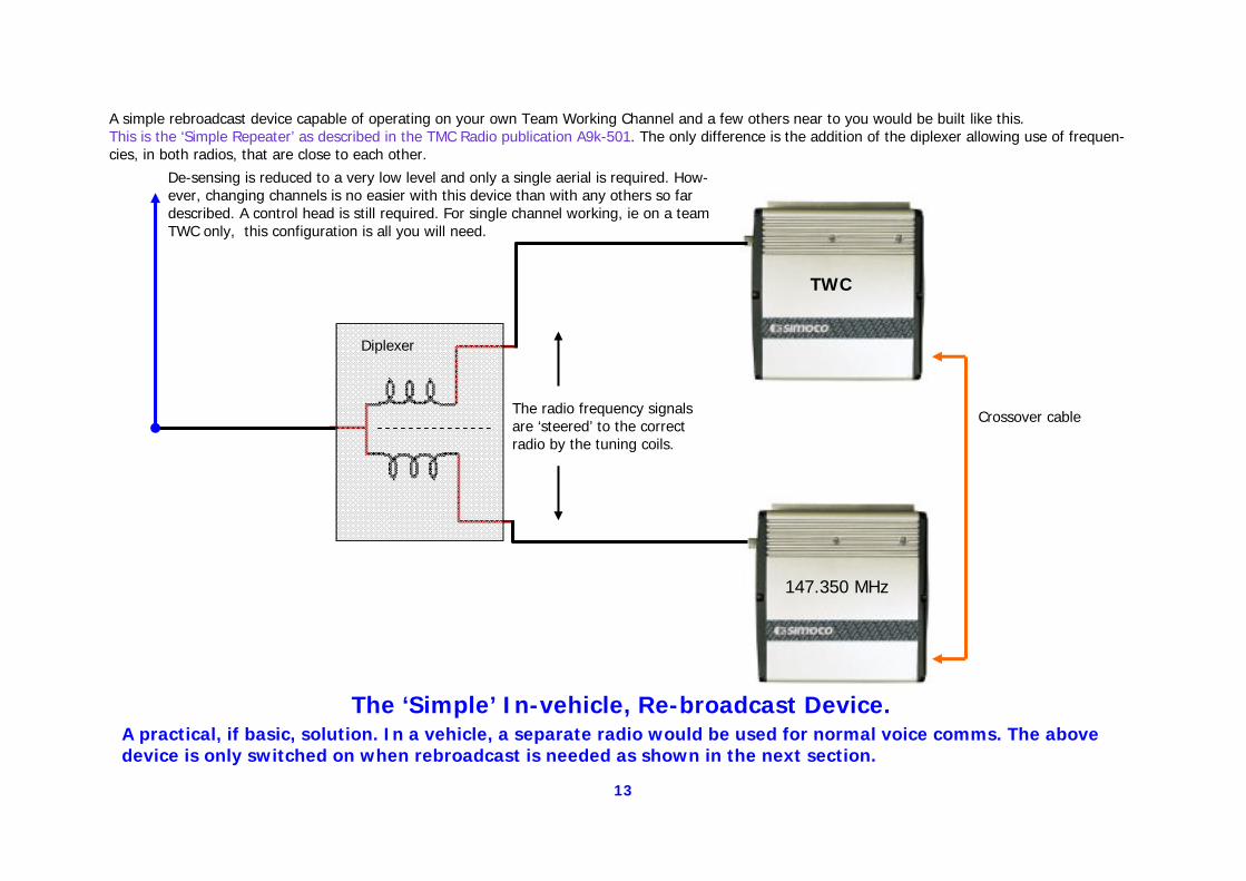
A simple rebroadcast device capable of operating on your own Team Working Channel and a few others near to you would be built like this. This is the ‘Simple Repeater’ as described in the TMC Radio publication A9k-501. The only difference is the addition of the diplexer allowing use of frequen-cies, in both radios, that are close to each other.
De-sensing is reduced to a very low level and only a single aerial is required. How-ever, changing channels is no easier with this device than with any others so far described. A control head is still required. For single channel working, ie on a team TWC only, this configuration is all you will need.
TWC
147.350 MHz
The radio frequency signals are ‘steered’ to the correct radio by the tuning coils.
Diplexer
Crossover cable
The ‘Simple’ In-vehicle, Re-broadcast Device. A practical, if basic, solution. In a vehicle, a separate radio would be used for normal voice comms. The above device is only switched on when rebroadcast is needed as shown in the next section.
14
The TMC Radio ‘Simplest’ Repeater
This is probably the method that most teams initially looked at and the one several teams now use. It works fine with a little training and it’s only real fault is the need for three radios and two aerials for each vehicle. Having said that, it’s a very flexible and reliable method of setting up a vehicle rebroadcast system and some teams may need to go no further than this.
To run the system efficiently, you do need to have the facility to switch off the pair of radios making up the rebroadcast section. They really only need to be powered up when the rebroadcast is in use.
15
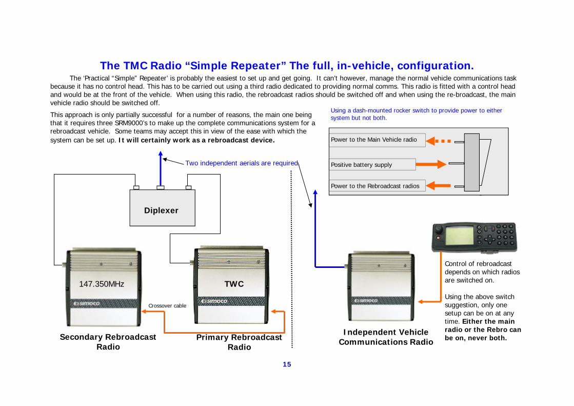
The TMC Radio “Simple Repeater” The full, in-vehicle, configuration. The ‘Practical “Simple” Repeater’ is probably the easiest to set up and get going. It can’t however, manage the normal vehicle communications task because it has no control head. This has to be carried out using a third radio dedicated to providing normal comms. This radio is fitted with a control head and would be at the front of the vehicle. When using this radio, the rebroadcast radios should be switched off and when using the re-broadcast, the main vehicle radio should be switched off.
TWC 147.350MHz
Secondary Rebroadcast Radio
Primary Rebroadcast Radio
Control of rebroadcast depends on which radios are switched on. Using the above switch suggestion, only one setup can be on at any time. Either the main radio or the Rebro can be on, never both.
Diplexer
Independent Vehicle Communications Radio
Two independent aerials are required. Positive battery supply
Power to the Main Vehicle radio
Power to the Rebroadcast radios
Crossover cable
Using a dash-mounted rocker switch to provide power to either system but not both. This approach is only partially successful for a number of reasons, the main one being
that it requires three SRM9000’s to make up the complete communications system for a rebroadcast vehicle. Some teams may accept this in view of the ease with which the system can be set up. It will certainly work as a rebroadcast device.
16
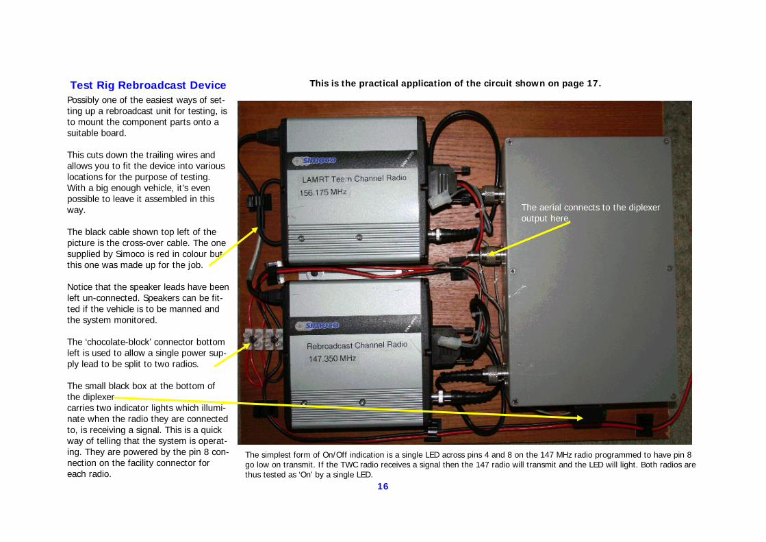
Test Rig Rebroadcast Device Possibly one of the easiest ways of set-ting up a rebroadcast unit for testing, is to mount the component parts onto a suitable board. This cuts down the trailing wires and allows you to fit the device into various locations for the purpose of testing. With a big enough vehicle, it’s even possible to leave it assembled in this way. The black cable shown top left of the picture is the cross-over cable. The one supplied by Simoco is red in colour but this one was made up for the job. Notice that the speaker leads have been left un-connected. Speakers can be fit-ted if the vehicle is to be manned and the system monitored. The ‘chocolate-block’ connector bottom left is used to allow a single power sup-ply lead to be split to two radios. The small black box at the bottom of the diplexer carries two indicator lights which illumi-nate when the radio they are connected to, is receiving a signal. This is a quick way of telling that the system is operat-ing. They are powered by the pin 8 con-nection on the facility connector for each radio.
This is the practical application of the circuit shown on page 17.
The aerial connects to the diplexer output here.
The simplest form of On/Off indication is a single LED across pins 4 and 8 on the 147 MHz radio programmed to have pin 8 go low on transmit. If the TWC radio receives a signal then the 147 radio will transmit and the LED will light. Both radios are thus tested as ‘On’ by a single LED.
17
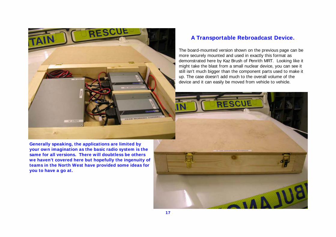
A Transportable Rebroadcast Device. The board-mounted version shown on the previous page can be more securely mounted and used in exactly this format as demonstrated here by Kaz Brush of Penrith MRT. Looking like it might take the blast from a small nuclear device, you can see it still isn’t much bigger than the component parts used to make it up. The case doesn’t add much to the overall volume of the device and it can easily be moved from vehicle to vehicle.
Generally speaking, the applications are limited by your own imagination as the basic radio system is the same for all versions. There will doubtless be others we haven’t covered here but hopefully the ingenuity of teams in the North West have provided some ideas for you to have a go at.
18
The TMC Radio ‘Standard’ Repeater
This is where things get a little more complicated
As already mentioned, the problem with the previous version is the need for a separate radio to handle normal voice comms to and from the vehicle when the rebroadcast device isn’t in use. It’s possible to have only two radios handle the job of both normal comms and rebroadcast but you are now into the realms of additional accessory boards. With the next few suggested con-figurations, the level of technical complexity increases.
You are recommended to visit the TMC Radio website and to download the files A9k-821` ‘Dual transceivers using a common control’ and the ‘MA-DMAP Option Board Technical Manual v2’ www.tmcradio.com
19
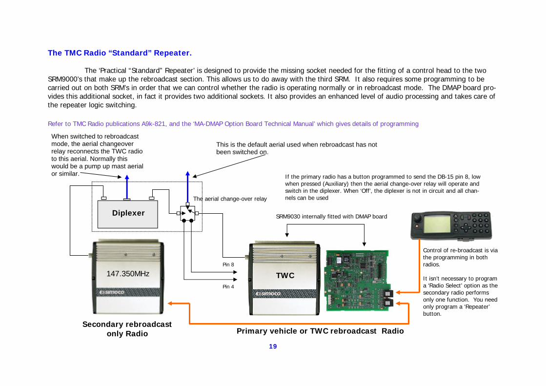
The TMC Radio “Standard” Repeater. The ‘Practical “Standard” Repeater’ is designed to provide the missing socket needed for the fitting of a control head to the two SRM9000’s that make up the rebroadcast section. This allows us to do away with the third SRM. It also requires some programming to be carried out on both SRM’s in order that we can control whether the radio is operating normally or in rebroadcast mode. The DMAP board pro-vides this additional socket, in fact it provides two additional sockets. It also provides an enhanced level of audio processing and takes care of the repeater logic switching.
SRM9030 internally fitted with DMAP board
TWC 147.350MHz
Secondary rebroadcast only Radio Primary vehicle or TWC rebroadcast Radio
Control of re-broadcast is via the programming in both radios. It isn’t necessary to program a ‘Radio Select’ option as the secondary radio performs only one function. You need only program a ‘Repeater’ button.
Diplexer
Pin 8
Pin 4
If the primary radio has a button programmed to send the DB-15 pin 8, low when pressed (Auxiliary) then the aerial change-over relay will operate and switch in the diplexer. When ‘Off’, the diplexer is not in circuit and all chan-nels can be used The aerial change-over relay
Refer to TMC Radio publications A9k-821, and the ‘MA-DMAP Option Board Technical Manual’ which gives details of programming
This is the default aerial used when rebroadcast has not been switched on.
When switched to rebroadcast mode, the aerial changeover relay reconnects the TWC radio to this aerial. Normally this would be a pump up mast aerial or similar.
20
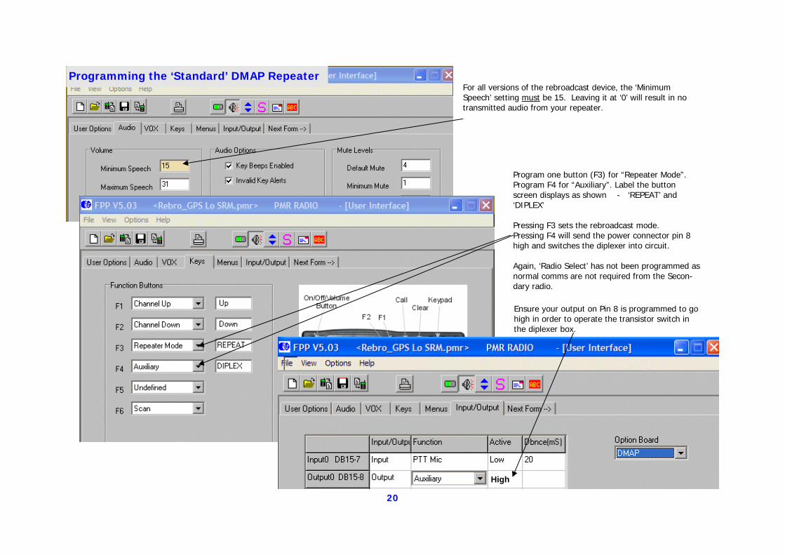
For all versions of the rebroadcast device, the ‘Minimum Speech’ setting must be 15. Leaving it at ‘0’ will result in no transmitted audio from your repeater.
Program one button (F3) for “Repeater Mode”. Program F4 for “Auxiliary”. Label the button screen displays as shown - ‘REPEAT’ and ‘DIPLEX’ Pressing F3 sets the rebroadcast mode. Pressing F4 will send the power connector pin 8 high and switches the diplexer into circuit. Again, ‘Radio Select’ has not been programmed as normal comms are not required from the Secon-dary radio.
Ensure your output on Pin 8 is programmed to go high in order to operate the transistor switch in the diplexer box.
Programming the ‘Standard’ DMAP Repeater
High
21
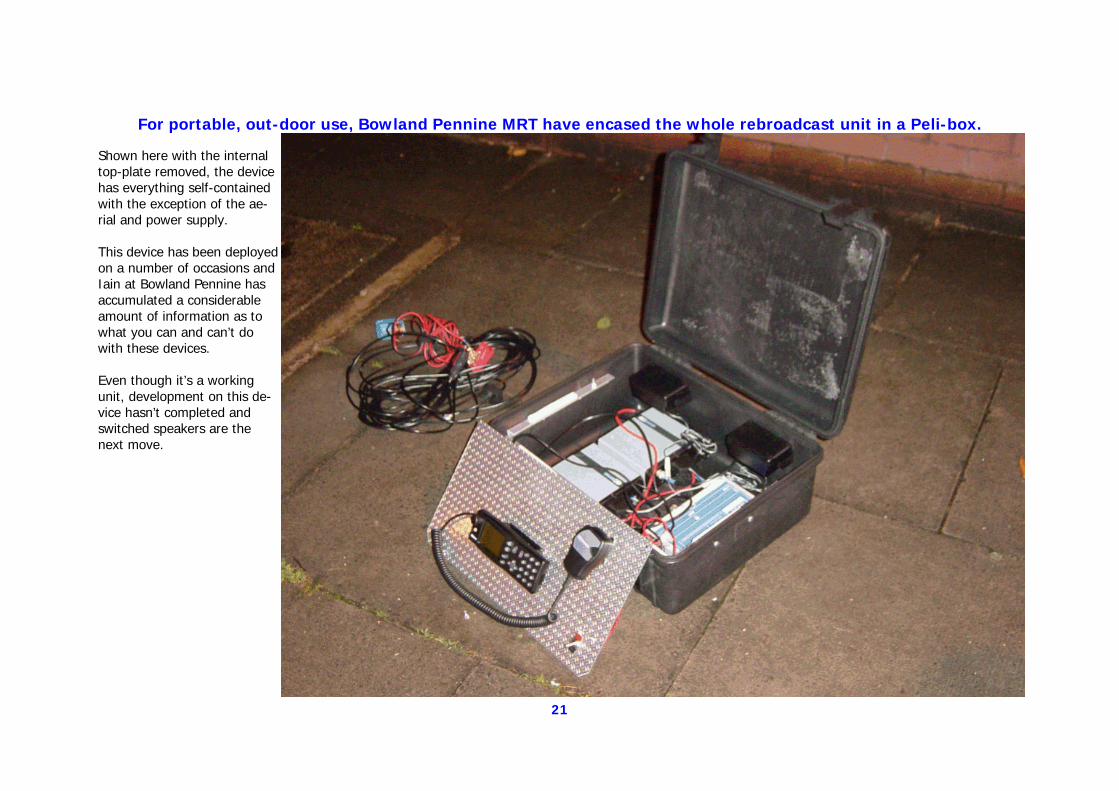
For portable, out-door use, Bowland Pennine MRT have encased the whole rebroadcast unit in a Peli-box.
Shown here with the internal top-plate removed, the device has everything self-contained with the exception of the ae-rial and power supply. This device has been deployed on a number of occasions and Iain at Bowland Pennine has accumulated a considerable amount of information as to what you can and can’t do with these devices. Even though it’s a working unit, development on this de-vice hasn’t completed and switched speakers are the next move.
22
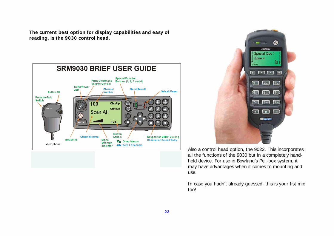
The current best option for display capabilities and easy of reading, is the 9030 control head.
Also a control head option, the 9022. This incorporates all the functions of the 9030 but in a completely hand-held device. For use in Bowland’s Peli-box system, it may have advantages when it comes to mounting and use. In case you hadn’t already guessed, this is your fist mic too!
23
A recommended improvement providing a more elegant solution to the problem.
Here, the suggestions again get a little more complex and the ability to follow an electrical diagram is a great help.
We have to stress here that any additional assistance needed with these configurations can be got from either myself or the contributing team.
24
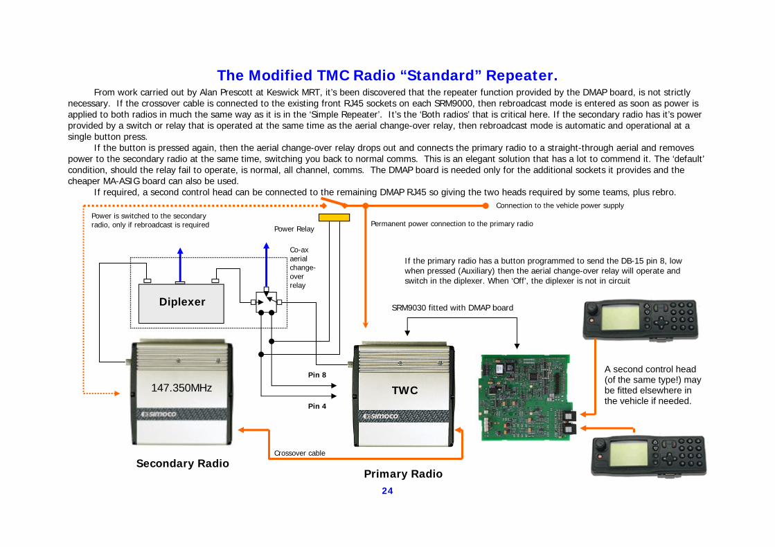
The Modified TMC Radio “Standard” Repeater. From work carried out by Alan Prescott at Keswick MRT, it’s been discovered that the repeater function provided by the DMAP board, is not strictly necessary. If the crossover cable is connected to the existing front RJ45 sockets on each SRM9000, then rebroadcast mode is entered as soon as power is applied to both radios in much the same way as it is in the ‘Simple Repeater’. It’s the ‘Both radios’ that is critical here. If the secondary radio has it’s power provided by a switch or relay that is operated at the same time as the aerial change-over relay, then rebroadcast mode is automatic and operational at a single button press. If the button is pressed again, then the aerial change-over relay drops out and connects the primary radio to a straight-through aerial and removes power to the secondary radio at the same time, switching you back to normal comms. This is an elegant solution that has a lot to commend it. The ‘default’ condition, should the relay fail to operate, is normal, all channel, comms. The DMAP board is needed only for the additional sockets it provides and the cheaper MA-ASIG board can also be used. If required, a second control head can be connected to the remaining DMAP RJ45 so giving the two heads required by some teams, plus rebro.
SRM9030 fitted with DMAP board
TWC 147.350MHz
Secondary Radio Primary Radio
Diplexer
Pin 8
Pin 4
If the primary radio has a button programmed to send the DB-15 pin 8, low when pressed (Auxiliary) then the aerial change-over relay will operate and switch in the diplexer. When ‘Off’, the diplexer is not in circuit
Power Relay
Power is switched to the secondary radio, only if rebroadcast is required
Connection to the vehicle power supply
Permanent power connection to the primary radio
Crossover cable
Co-ax aerial change-over relay
A second control head (of the same type!) may be fitted elsewhere in the vehicle if needed.
25
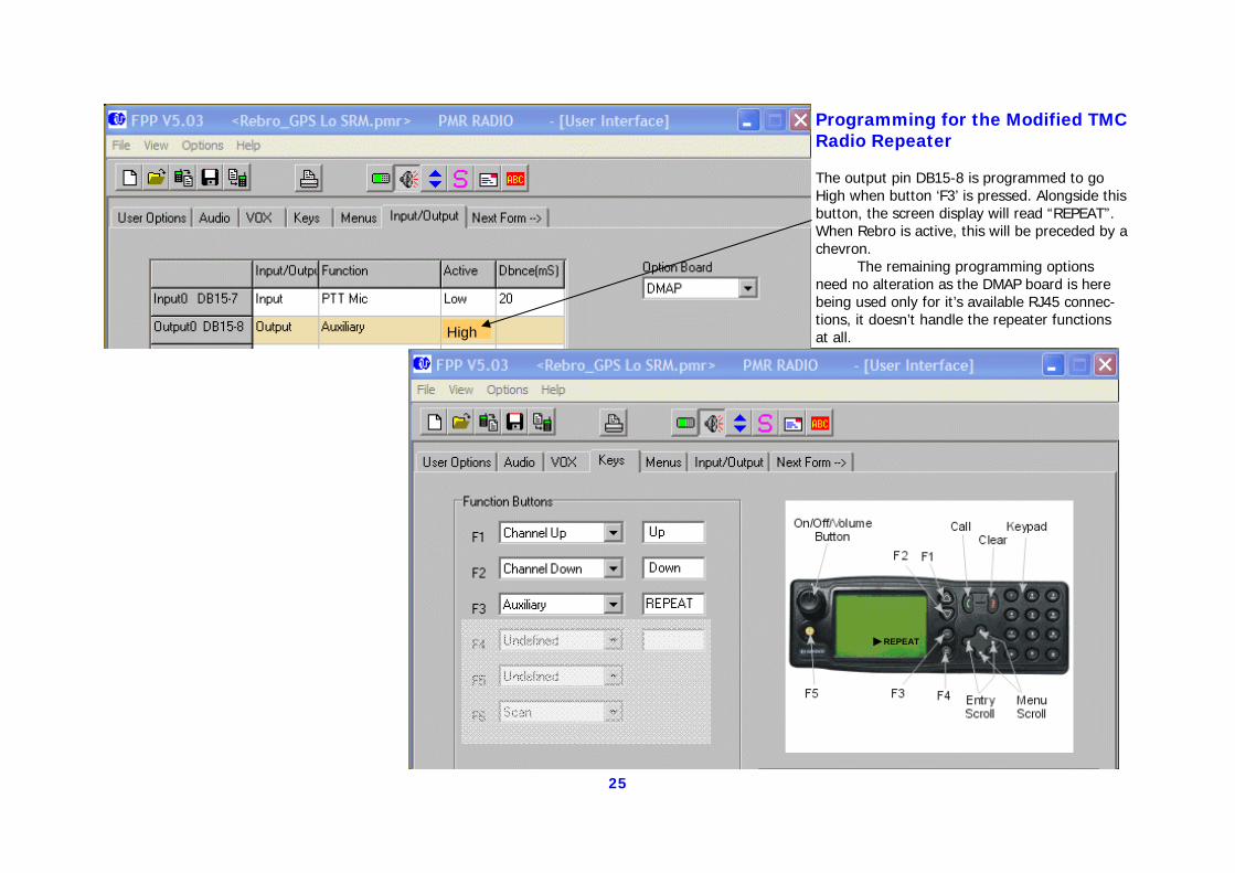
Programming for the Modified TMC Radio Repeater The output pin DB15-8 is programmed to go High when button ‘F3’ is pressed. Alongside this button, the screen display will read “REPEAT”. When Rebro is active, this will be preceded by a chevron. The remaining programming options need no alteration as the DMAP board is here being used only for it’s available RJ45 connec-tions, it doesn’t handle the repeater functions at all.
REPEAT
High
26
Manually Switched Rebroadcast Mode
Probably the easiest and most efficient method of implementing vehicle comms and rebroadcast from a pair of SRM9000 radios.
This configuration doesn’t rely on programming of the radios in order to achieve switch-over from standard vehicle comms to rebroadcast. Instead it uses a basic
change-over switch which, when operated, powers both the secondary radio and the aerial change-over relay. It requires only a switch on the dash of your vehicle which is
labelled ‘Normal Comms / Rebroadcast’ or however you want to phrase it.
For it’s ease of implementation and use, this method has a lot to commend it.
27
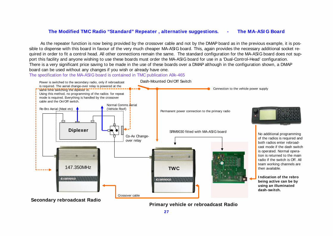
The Modified TMC Radio “Standard” Repeater , alternative suggestions. - The MA-ASIG Board As the repeater function is now being provided by the crossover cable and not by the DMAP board as in the previous example, it is pos-sible to dispense with this board in favour of the very much cheaper MA-ASIG board. This, again provides the necessary additional socket re-quired in order to fit a control head. All other connections remain the same. The standard configuration for the MA-ASIG board does not sup-port this facility and anyone wishing to use these boards must order the MA-ASIG board for use in a ‘Dual-Control-Head’ configuration. There is a very significant price saving to be made in the use of these boards over a DMAP although in the configuration shown, a DMAP board can be used without any changes if you wish or already have one. The specification for the MA-ASIG board is contained in TMC publication A9k-465
SRM9030 fitted with MA-ASIG board
TWC 147.350MHz
Secondary rebroadcast Radio Primary vehicle or rebroadcast Radio
Diplexer No additional programming of the radios is required and both radios enter rebroad-cast mode if the dash switch is operated. Normal opera-tion is returned to the main radio if the switch is Off. All team working channels are then available. Indication of the rebro being active can be by using an illuminated dash-switch.
Power is switched to the secondary radio, only if rebroadcast is required. The aerial change-over relay is powered at the same time switching the diplexer in. Using this method, no programming of the radios for repeat mode is required. Everything is handled by the crossover cable and the On/Off switch.
Connection to the vehicle power supply
Permanent power connection to the primary radio
Crossover cable
Re-Bro Aerial (Mast etc) Normal Comms Aerial (Vehicle Roof)
Dash-Mounted On/Off Switch
Co-Ax Change-over relay
28
Although a much easier solution, the previous example was still complicated by the fact that the diplexer needs to be present to
keep the frequencies in each radio, apart.
If a cross band system is used where the rebroadcast link from the vehicle to the base is on a different band, the old low band channels being the most obvious for experi-mentation, then no diplexer is needed and the system is very much simpler to setup.
In the example shown on the next page, a button on the control head has been pro-grammed for and Auxiliary output on Pin 8 of the power connector. This method can easily be replaced by the dash-mounted switch shown in the previous example but as
there is no diplexer relay to also be operated, only one button needs to be pro-grammed to switch the system on and off so this is probably the more elegant solution
29
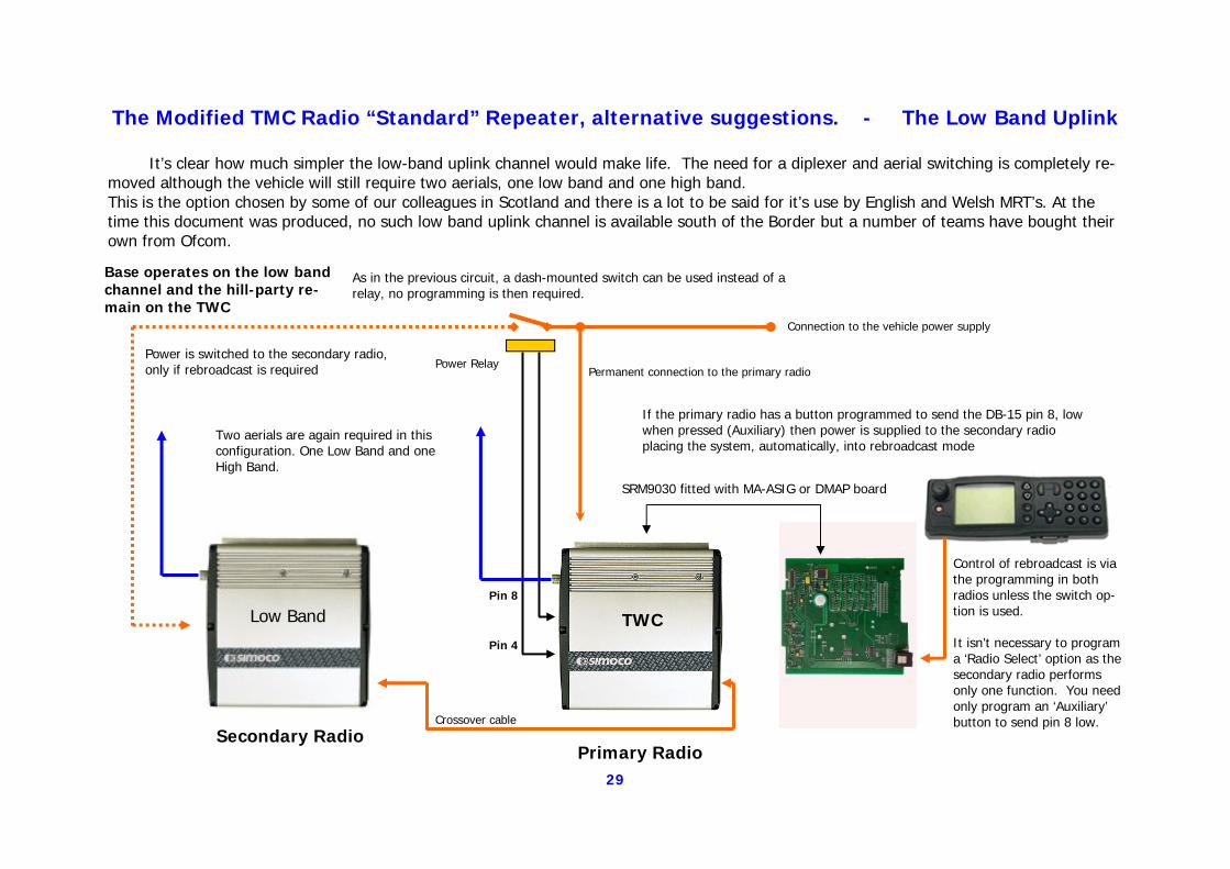
The Modified TMC Radio “Standard” Repeater, alternative suggestions. - The Low Band Uplink It’s clear how much simpler the low-band uplink channel would make life. The need for a diplexer and aerial switching is completely re-moved although the vehicle will still require two aerials, one low band and one high band. This is the option chosen by some of our colleagues in Scotland and there is a lot to be said for it’s use by English and Welsh MRT’s. At the time this document was produced, no such low band uplink channel is available south of the Border but a number of teams have bought their own from Ofcom.
SRM9030 fitted with MA-ASIG or DMAP board
TWC Low Band
Secondary Radio Primary Radio
Control of rebroadcast is via the programming in both radios unless the switch op-tion is used. It isn’t necessary to program a ‘Radio Select’ option as the secondary radio performs only one function. You need only program an ‘Auxiliary’ button to send pin 8 low.
Pin 8
Pin 4
If the primary radio has a button programmed to send the DB-15 pin 8, low when pressed (Auxiliary) then power is supplied to the secondary radio placing the system, automatically, into rebroadcast mode
Power Relay Power is switched to the secondary radio, only if rebroadcast is required
Connection to the vehicle power supply
Permanent connection to the primary radio
Crossover cable
As in the previous circuit, a dash-mounted switch can be used instead of a relay, no programming is then required.
Two aerials are again required in this configuration. One Low Band and one High Band.
Base operates on the low band channel and the hill-party re-main on the TWC
30
Extending the Capabilities of the Standard Repeater.
At this point there are hopefully enough options for you to select one you think will suit the needs of your team. Most of those requiring buttons to be programmed on the
control head can also be used with simple dash-mounted switches. It’s perfectly possi-ble to mix and match the methods used in each of these examples. This is already a
large document, there wasn’t room to include all the variations!
If you’re happy with one of the suggested solutions then I’d strongly recommend you get it up and running before going any further. The next section includes some addi-tional suggestions for enhancing what you now have, hopefully, a working, vehicle
mounted, rebroadcast system.
31
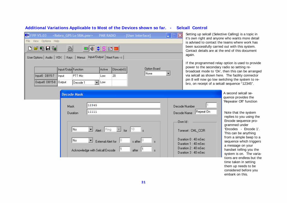
Additional Variations Applicable to Most of the Devices shown so far. - Selcall Control Setting up selcall (Selective Calling) is a topic in it’s own right and anyone who wants more detail is advised to contact the teams where work has been successfully carried out with this system. Contact details are at the end of this document again. If the programmed relay option is used to provide power to the secondary radio so setting re-broadcast mode to ‘On’, then this can be arranged via selcall as shown here. The facility connector pin 8 will now go low switching the system to re-bro, on receipt of a selcall sequence “12345”.
Note that the system replies to you using the Encode sequence pro-grammed under ‘Encodes - Encode 1’. This can be anything from a simple beep to a sequence which triggers a message on your handset telling you the system is on. The varia-tions are endless but the time taken in setting them up needs to be considered before you embark on this.
A second selcall se-quence provides the ‘Repeater Off’ function

32
Dave Binks at Duddon & Furness has designed and adopted a system where both radios can be independently used on all channels and a significant level of control via selcall is available. Individual rebro vehicles may be remotely activated and the user is advised as to which rebro he or she has just switched on. Operation of the system is best left to his own words and the following section has been supplied by Dave. His diplexer requires modification beyond that already undertaken, on our behalf, by Roger Taylor and a picture of the finished article with the lid removed, is shown below.
Dave’s modifications involve the fitting and control of an additional relay but the functioning of the device is still based upon the TMC DMAP repeater that has been enhanced by both software and hardware mods. This is the most sophisticated system we currently have available to us and the needs of each team as assessed by the radio officer will fall somewhere between the very simple and the version shown here. It all depends on what you think your team can handle successfully as someone’s life might really depend on the proper functioning of these devices! Build what you think your team can cope with.
33
THE DUDDON AND FURNESS MOUNTAIN RESCUE TEAM REBROADCAST SETUP Intro Rebroadcasting to most radios officers was a challenge, but to the average team members it meant absolutely nothing. After a little education, most then realised the benefits, although that was as far as many wanted to go. They were not interested in how it worked as long as it did. With this in mind, and the fact that we have large parts of our area that are not in radio range of the base without rebroadcasting, my aim was to make the system as easy to use and as idiot proof as possible thereby gaining the widest acceptance and subsequent usage by all team members. There are signs that I have achieved this aim, as a good number of members are now confident with their use. There follows a section detailing what each group of team members needs to know (Hill party, vehicle and base groups). Note: I use “repeater” and “rebroadcast” interchangeably in this document, although I am told it should always be “rebroadcast”!
Hill Party The hill party does not need to know anything. This is common to all the repeater setups providing the rebroadcast channel is used for the “base to the re-peater” jump and the TWC from the rebroadcast unit to the hill parties. Although it will usually be the base that controls the repeater, to allow flexibility, I have programmed one of the buttons on the side of the radio to enable a hill party to switch on/off one or other of our repeaters. This is all done through a single “control button” which is explained later.
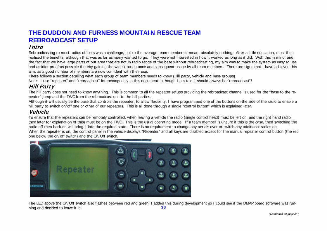
Vehicle To ensure that the repeaters can be remotely controlled, when leaving a vehicle the radio (single control head) must be left on, and the right hand radio (see later for explanation of this) must be on the TWC. This is the usual operating mode. If a team member is unsure if this is the case, then switching the radio off then back on will bring it into the required state. There is no requirement to change any aerials over or switch any additional radios on. When the repeater is on, the control panel in the vehicle displays “Repeater” and all keys are disabled except for the manual repeater control button (the red one below the on/off switch) and the On/Off switch.
The LED above the On/Off switch also flashes between red and green. I added this during development so I could see if the DMAP board software was run-ning and decided to leave it in!
(Continued on page 34)
34
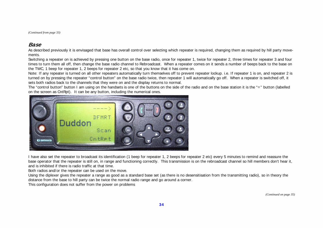
Base As described previously it is envisaged that base has overall control over selecting which repeater is required, changing them as required by hill party move-ments. Switching a repeater on is achieved by pressing one button on the base radio, once for repeater 1, twice for repeater 2, three times for repeater 3 and four times to turn them all off, then change the base radio channel to Rebroadcast. When a repeater comes on it sends a number of beeps back to the base on the TWC, 1 beep for repeater 1, 2 beeps for repeater 2 etc, so that you know that it has come on. Note: If any repeater is turned on all other repeaters automatically turn themselves off to prevent repeater lockup. i.e. If repeater 1 is on, and repeater 2 is turned on by pressing the repeater “control button” on the base radio twice, then repeater 1 will automatically go off. When a repeater is switched off, it sets both radios back to the channels that they were on and the display returns to normal. The “control button” button I am using on the handsets is one of the buttons on the side of the radio and on the base station it is the “=” button (labelled on the screen as CntRpt). It can be any button, including the numerical ones.
I have also set the repeater to broadcast its identification (1 beep for repeater 1, 2 beeps for repeater 2 etc) every 5 minutes to remind and reassure the base operator that the repeater is still on, in range and functioning correctly. This transmission is on the rebroadcast channel so hill members don’t hear it, and is inhibited if there is radio traffic at that time. Both radios and/or the repeater can be used on the move. Using the diplexer gives the repeater a range as good as a standard base set (as there is no desensitisation from the transmitting radio), so in theory the distance from the base to hill party can be twice the normal radio range and go around a corner. This configuration does not suffer from the power on problems
(Continued from page 33)
(Continued on page 35)
35
Technical Details Two independent radios When not in repeater mode you have 2 independent radios that can be used on all the SAR frequencies via the single control head. The head can be switched from radio to radio by pressing the top button on the radio – it’s labelled on the screen with an arrow pointing to the radio that it is currently con-trolling (“left” or “right” hand radio). Why 2 radios? 1) When the radios are turned on (single switch on the control head) the default state is the right hand radio on the TWC and the left hand one on the ECC channel thus complying with the requirement to monitor this channel (Although I believe this requirement is to be relaxed?). 2) When working with other teams (and coastguard) you can keep general chitchat on your own TWC while still monitoring and operating on the other team’s (or coastguard) channel. 3) When attending an incident, if expecting a helicopter (or even if you’re not), you can monitor CH53 as well as the TWC. 4) We don’t always man base during an incident because we can’t always get radio contact, even with repeaters, back to base from all areas. So we use one of the vehicles as a mobile base giving us 2 radios to control an incident. 5) If you get bored during a callout you can put one radio on scan and the other on the TWC. The setup makes best use of the 2 radios that you need to have installed to make a repeater.
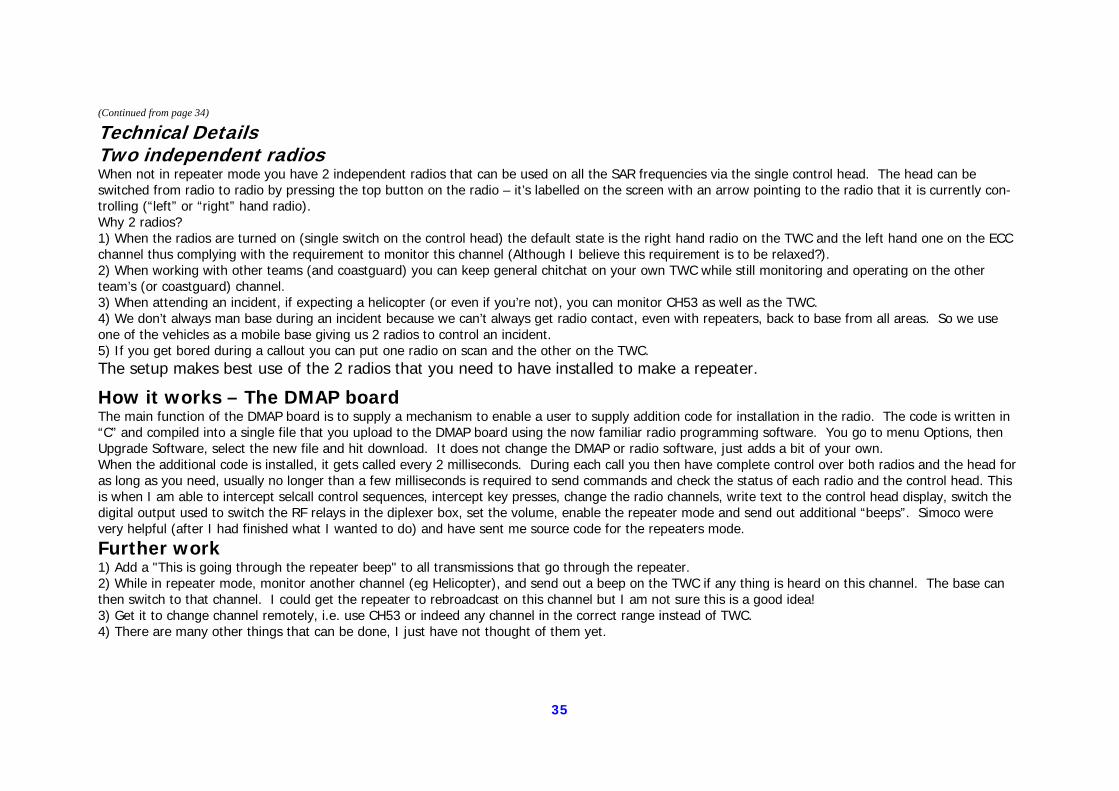
How it works – The DMAP board The main function of the DMAP board is to supply a mechanism to enable a user to supply addition code for installation in the radio. The code is written in “C” and compiled into a single file that you upload to the DMAP board using the now familiar radio programming software. You go to menu Options, then Upgrade Software, select the new file and hit download. It does not change the DMAP or radio software, just adds a bit of your own. When the additional code is installed, it gets called every 2 milliseconds. During each call you then have complete control over both radios and the head for as long as you need, usually no longer than a few milliseconds is required to send commands and check the status of each radio and the control head. This is when I am able to intercept selcall control sequences, intercept key presses, change the radio channels, write text to the control head display, switch the digital output used to switch the RF relays in the diplexer box, set the volume, enable the repeater mode and send out additional “beeps”. Simoco were very helpful (after I had finished what I wanted to do) and have sent me source code for the repeaters mode.
Further work 1) Add a "This is going through the repeater beep" to all transmissions that go through the repeater. 2) While in repeater mode, monitor another channel (eg Helicopter), and send out a beep on the TWC if any thing is heard on this channel. The base can then switch to that channel. I could get the repeater to rebroadcast on this channel but I am not sure this is a good idea! 3) Get it to change channel remotely, i.e. use CH53 or indeed any channel in the correct range instead of TWC. 4) There are many other things that can be done, I just have not thought of them yet.
(Continued from page 34)
36
A Remote Channel-Changing Fixed Repeater System designed To Remove The Need For Leased Telephone Land-Lines.
A number of teams in the Lakes use remote radio sites that are controlled over a leased telephone line. These have been found to be both expensive and prone to fail-ure from all manner of events from lightning strikes to a not so gentle shove with an earth-mover. Because of this I looked at methods of using a radio link rather than a land-line. Microwave links are expensive and so are not covered here although if any
team has any documented information on their use, I’d be happy to include it for you.
The chosen method was a closed, simplex link channel which can be anything you have a license for that is not in the same band as the UKSAR channels, here I mostly
use the low band channels between 71 and 86 MHz although I have used UHF channels with equal success but not over the distance afforded by low band.
As in the system developed by Dave Binks, this uses modified radio software not normally available but it can be arranged by contacting Rob Brookes.
37
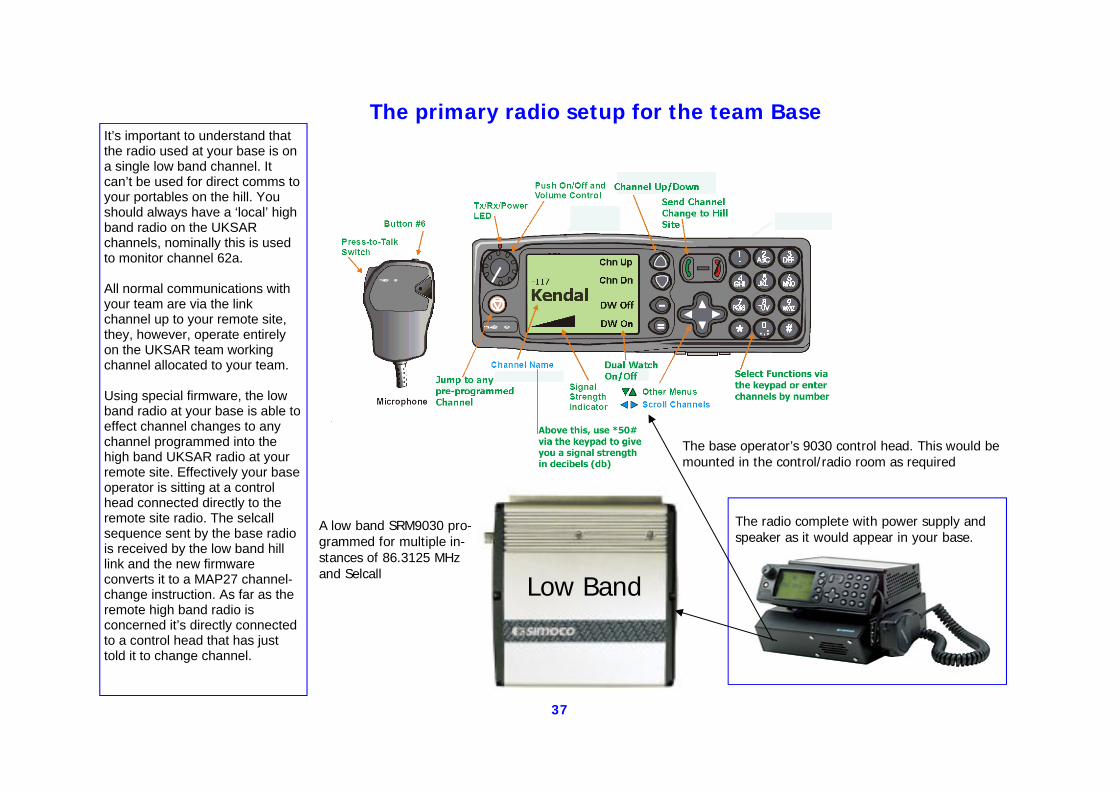
The primary radio setup for the team Base
The base operator’s 9030 control head. This would be mounted in the control/radio room as required
A low band SRM9030 pro-grammed for multiple in-stances of 86.3125 MHz and Selcall
Low Band
The radio complete with power supply and speaker as it would appear in your base.
It’s important to understand that the radio used at your base is on a single low band channel. It can’t be used for direct comms to your portables on the hill. You should always have a ‘local’ high band radio on the UKSAR channels, nominally this is used to monitor channel 62a. All normal communications with your team are via the link channel up to your remote site, they, however, operate entirely on the UKSAR team working channel allocated to your team. Using special firmware, the low band radio at your base is able to effect channel changes to any channel programmed into the high band UKSAR radio at your remote site. Effectively your base operator is sitting at a control head connected directly to the remote site radio. The selcall sequence sent by the base radio is received by the low band hill link and the new firmware converts it to a MAP27 channel-change instruction. As far as the remote high band radio is concerned it’s directly connected to a control head that has just told it to change channel.
38
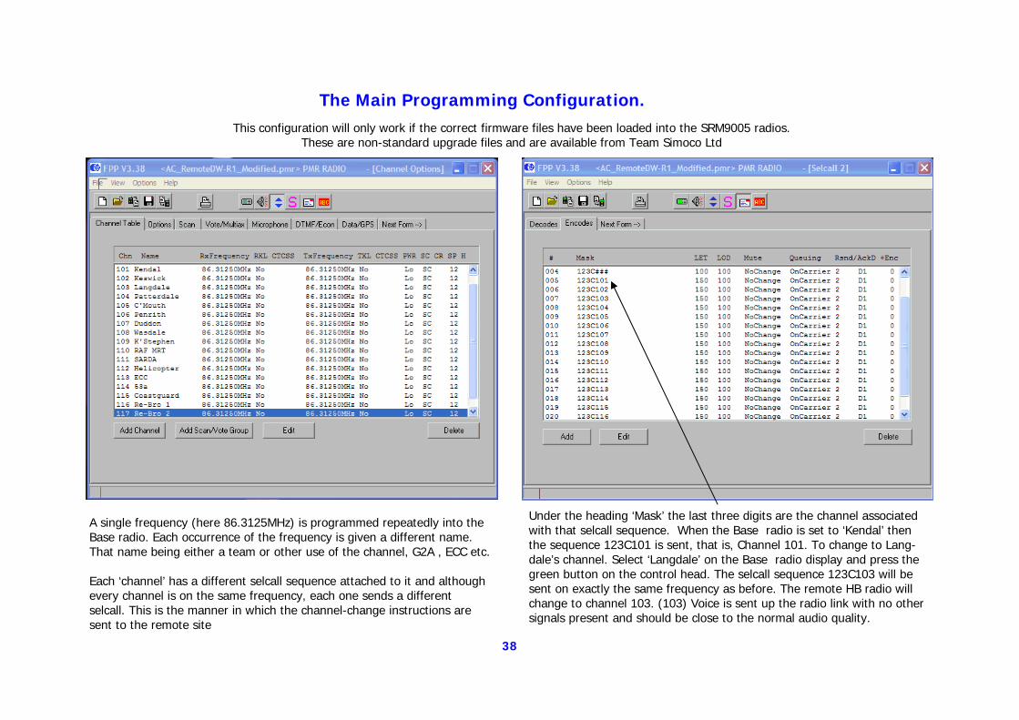
The Main Programming Configuration.
A single frequency (here 86.3125MHz) is programmed repeatedly into the Base radio. Each occurrence of the frequency is given a different name. That name being either a team or other use of the channel, G2A , ECC etc. Each ‘channel’ has a different selcall sequence attached to it and although every channel is on the same frequency, each one sends a different selcall. This is the manner in which the channel-change instructions are sent to the remote site
Under the heading ‘Mask’ the last three digits are the channel associated with that selcall sequence. When the Base radio is set to ‘Kendal’ then the sequence 123C101 is sent, that is, Channel 101. To change to Lang-dale’s channel. Select ‘Langdale’ on the Base radio display and press the green button on the control head. The selcall sequence 123C103 will be sent on exactly the same frequency as before. The remote HB radio will change to channel 103. (103) Voice is sent up the radio link with no other signals present and should be close to the normal audio quality.
This configuration will only work if the correct firmware files have been loaded into the SRM9005 radios. These are non-standard upgrade files and are available from Team Simoco Ltd
39
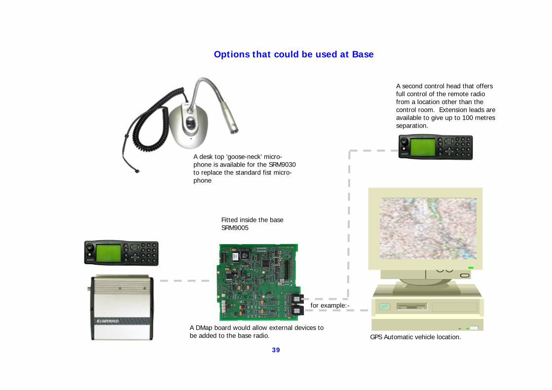
Options that could be used at Base
A DMap board would allow external devices to be added to the base radio. GPS Automatic vehicle location.
A desk top ‘goose-neck’ micro-phone is available for the SRM9030 to replace the standard fist micro-phone
A second control head that offers full control of the remote radio from a location other than the control room. Extension leads are available to give up to 100 metres separation.
for example:-
Fitted inside the base SRM9005
40
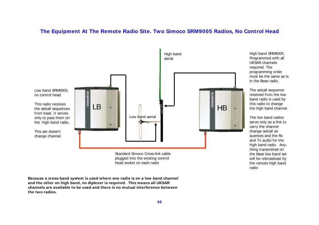
The Equipment At The Remote Radio Site. Two Simoco SRM9005 Radios, No Control Head
Low band SRM9005, no control head. This radio receives the selcall sequences from base. It serves only to pass them on the high band radio. This set doesn’t change channel.
Standard Simoco Cross-link cable plugged into the existing control head socket on each radio
High band SRM9005. Programmed with all UKSAR channels required. The programming order must be the same as is in the Base radio. The selcall sequence received from the low band radio is used by this radio to change the high band channel. The low band radios serve only as a link to carry the channel change selcall se-quences and the Rx and Tx audio for the high band radio. Any-thing transmitted on the Base low band set will be rebroadcast by the remote high band radio
Low band aerial
High band aerial
LB HB
Because a cross-band system is used where one radio is on a low band channel and the other on high band, no diplexer is required. This means all UKSAR channels are available to be used and there is no mutual interference between the two radios.
41
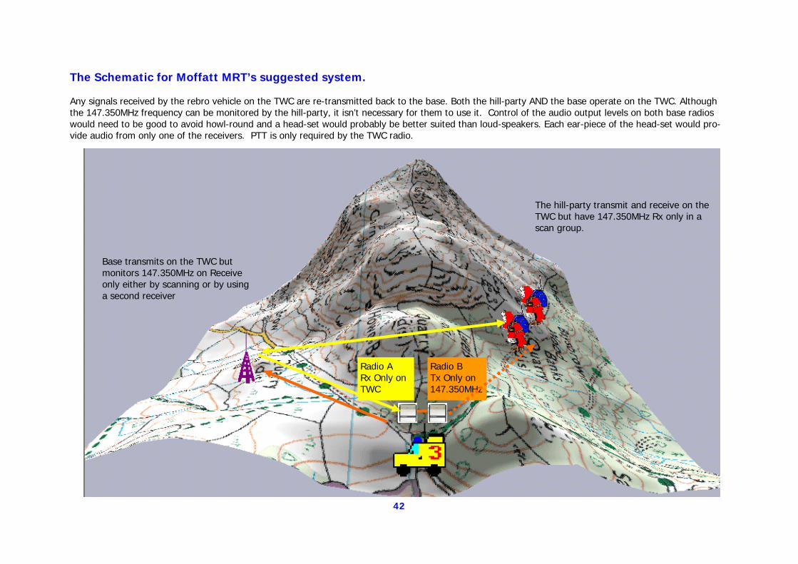
Moffatt MRT’s Suggested Rebro System: The following suggestion came from James Coles of Moffatt MRT and has considerable merit for it’s stated purpose. Eventually a significant number of teams will be using these devices and the chances of mutual interference goes up accordingly. Any means by which we can reduce this risk will increase the usefulness of the re-broadcast devices and allow more than one team to operate simultaneously with others with the minimum of interaction. James’ objective is to try and eliminate the possibility of 147.350 opening other team’s repeaters. His system requires that you program the repeater as a duplex unit with one radio only receiving on the TWC whilst the other would only transmit on 147.350. The base would monitor both the TWC and 147.350 but would only transmit on the Team Working Channel. Care would need to be taken to avoid acoustic feed-back here. The hill teams would work on the TWC and if they chose could have 147.350 as a receive only channel to listen to the repeater output in their scan group. Teams would only Tx on the TWC. This way if another team was deployed using their repeater the only interference would only be from the repeater and this would only open up the base radio monitoring 147.350 and anyone on the hill monitoring 147.350. With correct placement two repeaters could be deployed using different TWC with no fear of inference. 147.350 could be easily dropped from the scan group and revert to simplex communications on the TWC without any coordination required. The advantage of the system shown on the next page: If the Rebro unit fails back to back will continue function back to back where there is coverage. Hill parties can take advantage of the repeater to talk to teams non line of sight via TWC. Nobody needs to leave the TWC to transmit on another channel this is simple and safe. As the only device Transmitting on 147.350 is the repeater then other re-bro units in the same locality could use the channel too with correct repeater posi-tioning and thought.
42
Base transmits on the TWC but monitors 147.350MHz on Receive only either by scanning or by using a second receiver
The hill-party transmit and receive on the TWC but have 147.350MHz Rx only in a scan group.
Radio A Rx Only on TWC
Radio B Tx Only on 147.350MHz
The Schematic for Moffatt MRT’s suggested system. Any signals received by the rebro vehicle on the TWC are re-transmitted back to the base. Both the hill-party AND the base operate on the TWC. Although the 147.350MHz frequency can be monitored by the hill-party, it isn’t necessary for them to use it. Control of the audio output levels on both base radios would need to be good to avoid howl-round and a head-set would probably be better suited than loud-speakers. Each ear-piece of the head-set would pro-vide audio from only one of the receivers. PTT is only required by the TWC radio.
43
James’ system is interesting from the point of view that in Scotland, they’ve not used low band and never did have as many channels as we in the Lakes ended up with. As he points out in the accompanying emails, getting his colleagues to change channels is not as easy as we will find it as it has no historical precedent. As such, his system is very much geared to no one having to change channel but the method operation is not something we’re used to. Having now had it explained to me, it’s a perfectly viable system. Just one that we don’t happen to use down here. This works in the Borders but might be strange to us just as our system(s) would take some explaining to James’ colleagues. It goes to show just how much of a difference can exist but then again, having worked for many years with Lakes MRT’s, I already know that! James’ system is no less workable than any we’ve come up with, the critical factor for them all is that there has to be an access point for an ‘outside’ team or agency. We’re none of us quite at that stage just yet and in practice, probably only time will tell whether we are all going to be compatible on a major incident. What will be more critical before then but wasn’t intended to be a topic covered by this document, is that we at least all understand the differ-ences in teams who have adopted the new systems in slightly differing ways. This is one of the reasons that Tom considers monitoring of the ECC so important and it has to be said that having now seen examples of communications methods from teams spread over a not insignificant portion of the UK, I think he may well be right! My own team, Kendal, has a repeater that works but is not available to Langdale team whom we regularly support due to technical problems not easy to get round. We will got over all the hurdles and any team’s major priority is it’s own area and casualties. No one is about to dictate how you go about that because you’ve all been doing it for enough time now to know if you’re doing it right! All we can ask is that an open mind is kept on the ideas of all and that these ideas are not kept from others who might benefit from them. Now that IS the purpose of this document!!
44
An alternative approach to rebroadcast systems in team vehicles
This method uses the additional facility terminals available on the main power connector instead of the standard crossover lead. This leaves the radio RJ45 port
available for other tasks if required.
45
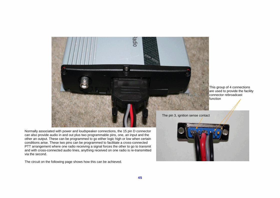
Normally associated with power and loudspeaker connections, the 15 pin D connector can also provide audio in and out plus two programmable pins, one, an input and the other an output. These can be programmed to go either logic high or low when certain conditions arise. These two pins can be programmed to facilitate a cross-connected PTT arrangement where one radio receiving a signal forces the other to go to transmit and with cross-connected audio lines, anything received on one radio is re-transmitted via the second. The circuit on the following page shows how this can be achieved.
This group of 4 connections are used to provide the facility connector rebroadcast function
The pin 3, ignition sense contact
46
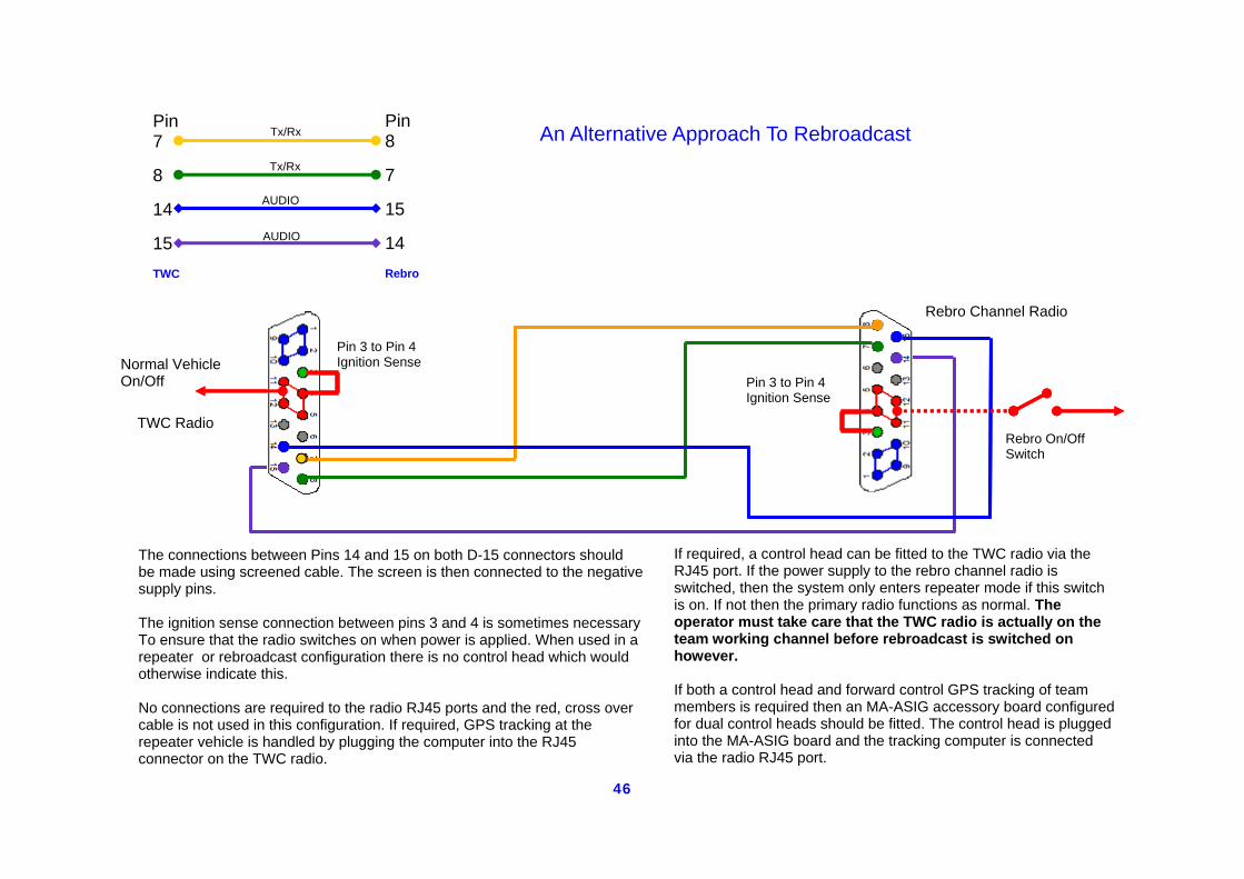
Pin 7 8 14 15 TWC
Pin 8 7 15 14 Rebro
Tx/Rx
Tx/Rx
AUDIO
AUDIO
Pin 3 to Pin 4 Ignition Sense
Pin 3 to Pin 4 Ignition Sense
The connections between Pins 14 and 15 on both D-15 connectors should be made using screened cable. The screen is then connected to the negative supply pins. The ignition sense connection between pins 3 and 4 is sometimes necessary To ensure that the radio switches on when power is applied. When used in a repeater or rebroadcast configuration there is no control head which would otherwise indicate this. No connections are required to the radio RJ45 ports and the red, cross over cable is not used in this configuration. If required, GPS tracking at the repeater vehicle is handled by plugging the computer into the RJ45 connector on the TWC radio.
TWC Radio
Rebro Channel Radio
If required, a control head can be fitted to the TWC radio via the RJ45 port. If the power supply to the rebro channel radio is switched, then the system only enters repeater mode if this switch is on. If not then the primary radio functions as normal. The operator must take care that the TWC radio is actually on the team working channel before rebroadcast is switched on however. If both a control head and forward control GPS tracking of team members is required then an MA-ASIG accessory board configured for dual control heads should be fitted. The control head is plugged into the MA-ASIG board and the tracking computer is connected via the radio RJ45 port.
An Alternative Approach To Rebroadcast
Rebro On/Off Switch
Normal Vehicle On/Off
47
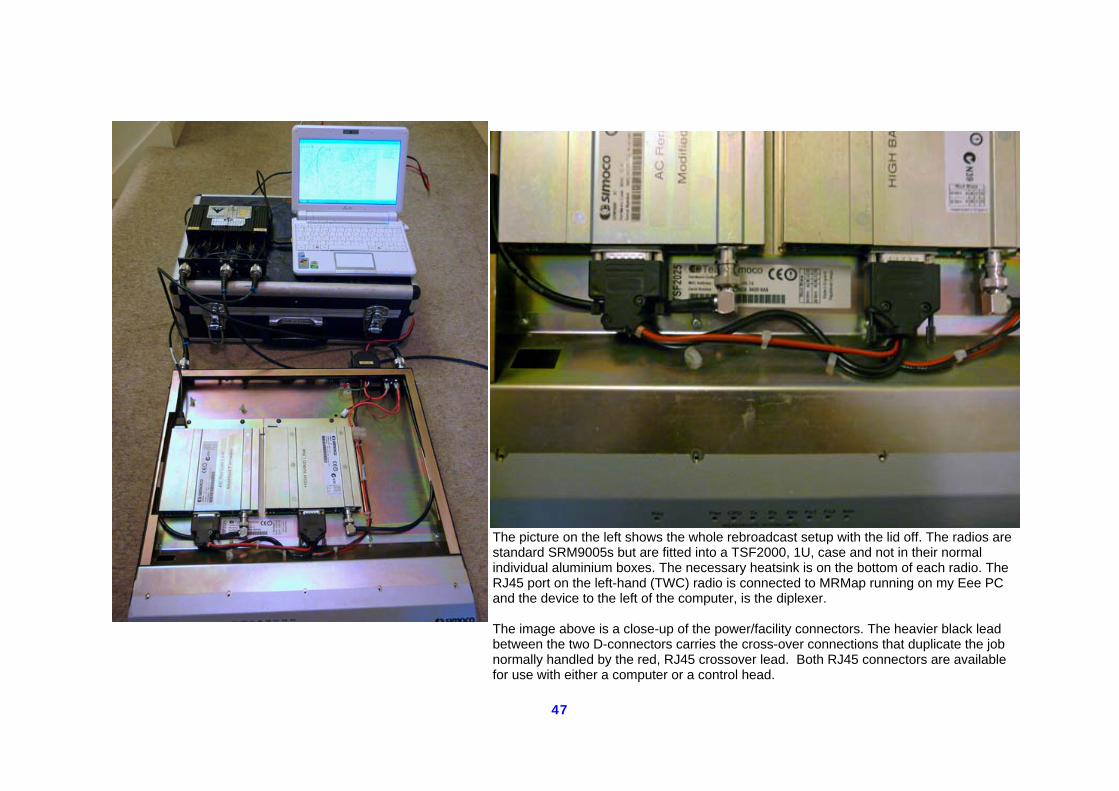
The picture on the left shows the whole rebroadcast setup with the lid off. The radios are standard SRM9005s but are fitted into a TSF2000, 1U, case and not in their normal individual aluminium boxes. The necessary heatsink is on the bottom of each radio. The RJ45 port on the left-hand (TWC) radio is connected to MRMap running on my Eee PC and the device to the left of the computer, is the diplexer. The image above is a close-up of the power/facility connectors. The heavier black lead between the two D-connectors carries the cross-over connections that duplicate the job normally handled by the red, RJ45 crossover lead. Both RJ45 connectors are available for use with either a computer or a control head.
48
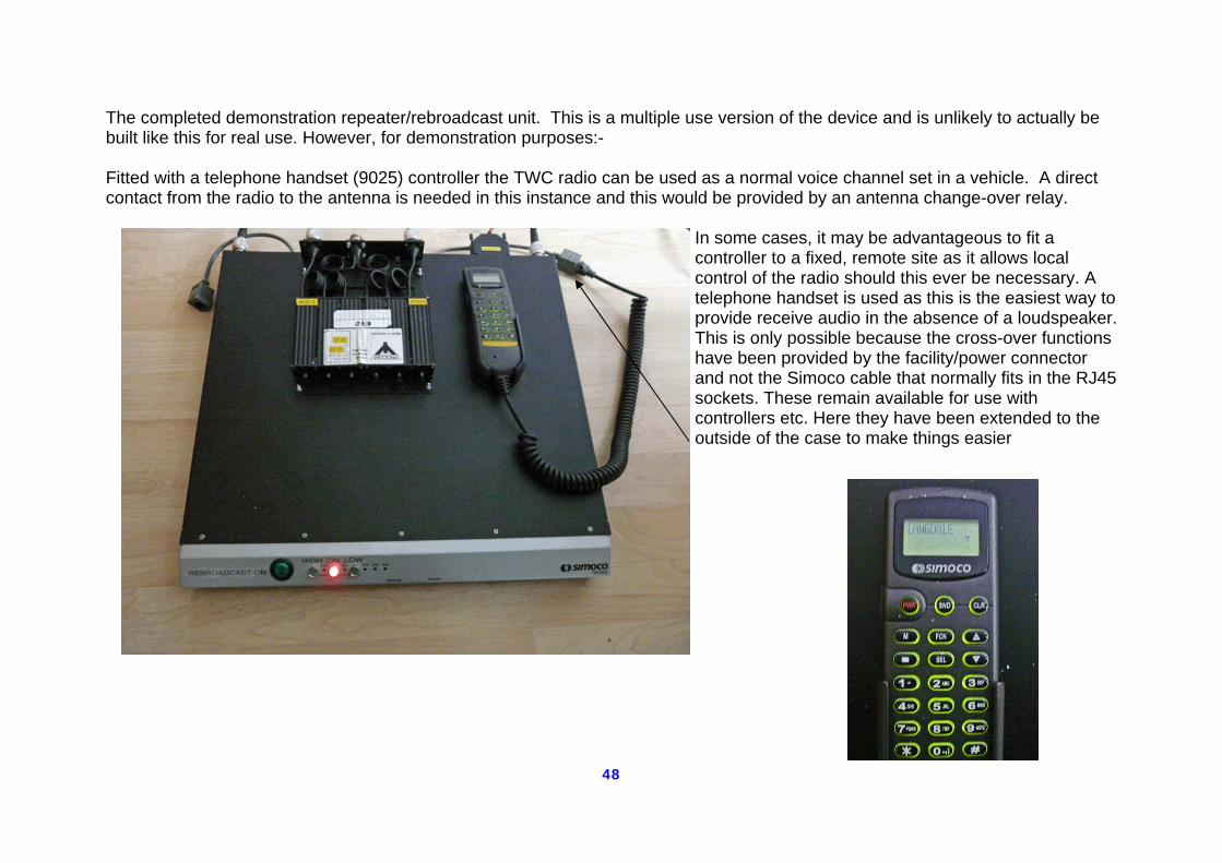
The completed demonstration repeater/rebroadcast unit. This is a multiple use version of the device and is unlikely to actually be built like this for real use. However, for demonstration purposes:- Fitted with a telephone handset (9025) controller the TWC radio can be used as a normal voice channel set in a vehicle. A direct contact from the radio to the antenna is needed in this instance and this would be provided by an antenna change-over relay.
In some cases, it may be advantageous to fit a controller to a fixed, remote site as it allows local control of the radio should this ever be necessary. A telephone handset is used as this is the easiest way to provide receive audio in the absence of a loudspeaker. This is only possible because the cross-over functions have been provided by the facility/power connector and not the Simoco cable that normally fits in the RJ45 sockets. These remain available for use with controllers etc. Here they have been extended to the outside of the case to make things easier
49
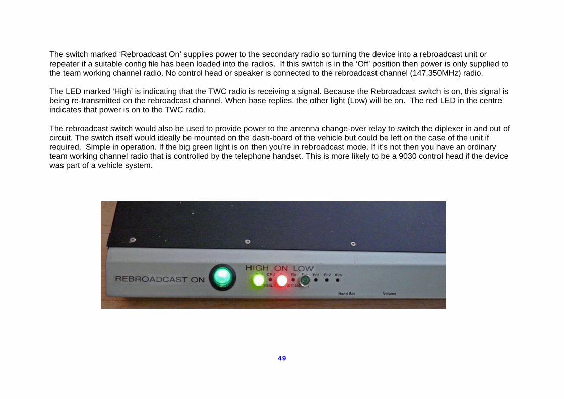
The switch marked ‘Rebroadcast On’ supplies power to the secondary radio so turning the device into a rebroadcast unit or repeater if a suitable config file has been loaded into the radios. If this switch is in the ‘Off’ position then power is only supplied to the team working channel radio. No control head or speaker is connected to the rebroadcast channel (147.350MHz) radio. The LED marked ‘High’ is indicating that the TWC radio is receiving a signal. Because the Rebroadcast switch is on, this signal is being re-transmitted on the rebroadcast channel. When base replies, the other light (Low) will be on. The red LED in the centre indicates that power is on to the TWC radio. The rebroadcast switch would also be used to provide power to the antenna change-over relay to switch the diplexer in and out of circuit. The switch itself would ideally be mounted on the dash-board of the vehicle but could be left on the case of the unit if required. Simple in operation. If the big green light is on then you’re in rebroadcast mode. If it’s not then you have an ordinary team working channel radio that is controlled by the telephone handset. This is more likely to be a 9030 control head if the device was part of a vehicle system.
50
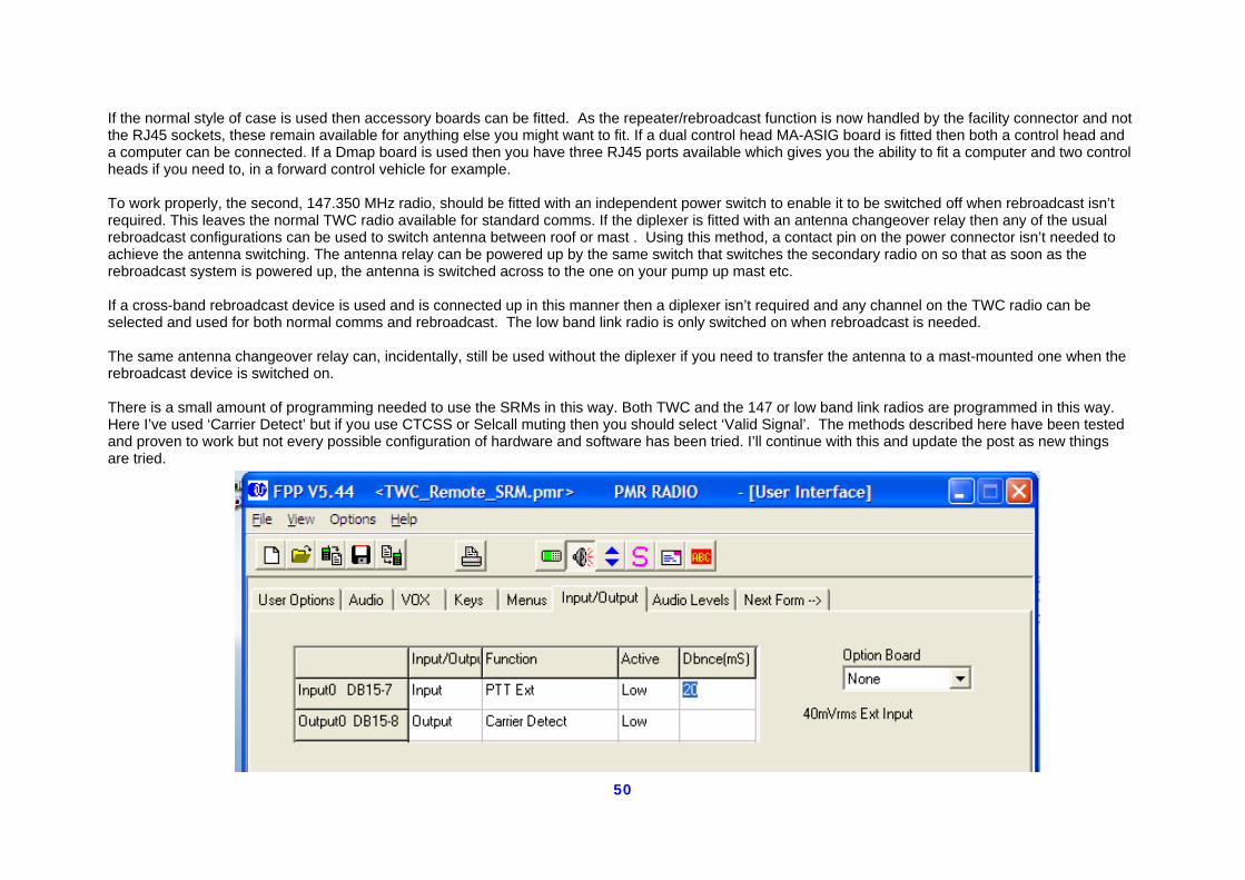
If the normal style of case is used then accessory boards can be fitted. As the repeater/rebroadcast function is now handled by the facility connector and not the RJ45 sockets, these remain available for anything else you might want to fit. If a dual control head MA-ASIG board is fitted then both a control head and a computer can be connected. If a Dmap board is used then you have three RJ45 ports available which gives you the ability to fit a computer and two control heads if you need to, in a forward control vehicle for example. To work properly, the second, 147.350 MHz radio, should be fitted with an independent power switch to enable it to be switched off when rebroadcast isn’t required. This leaves the normal TWC radio available for standard comms. If the diplexer is fitted with an antenna changeover relay then any of the usual rebroadcast configurations can be used to switch antenna between roof or mast . Using this method, a contact pin on the power connector isn’t needed to achieve the antenna switching. The antenna relay can be powered up by the same switch that switches the secondary radio on so that as soon as the rebroadcast system is powered up, the antenna is switched across to the one on your pump up mast etc. If a cross-band rebroadcast device is used and is connected up in this manner then a diplexer isn’t required and any channel on the TWC radio can be selected and used for both normal comms and rebroadcast. The low band link radio is only switched on when rebroadcast is needed. The same antenna changeover relay can, incidentally, still be used without the diplexer if you need to transfer the antenna to a mast-mounted one when the rebroadcast device is switched on. There is a small amount of programming needed to use the SRMs in this way. Both TWC and the 147 or low band link radios are programmed in this way. Here I’ve used ‘Carrier Detect’ but if you use CTCSS or Selcall muting then you should select ‘Valid Signal’. The methods described here have been tested and proven to work but not every possible configuration of hardware and software has been tried. I’ll continue with this and update the post as new things are tried.
51
The rebroadcast version of this setup has been tested using CTCSS on both receive and transmit for all radios. Voice and GPS data both passed through the system at range without any apparent difficulty. The current operating frequencies are 147.350 MHz for the rebro link channel and Langdale’s team working channel of 156.175 MHz. These channels are not as far apart as some others are and the level of channel separation afforded by the diplexer allows a significant range to be achieved even when both radios are running at 25 watts transmit power. The significant advantage of this setup for fixed site use is that only one high band antenna is required at the remote site. In the Lake District, we are blessed with some very obliging farmers, landowners and residents all of whom are helping to provide teams with remote antenna sites. However we are eternally mindful of the fact that we live and operate inside a national park where planning restrictions frequently make their presence felt. The ability to get a radio linked remote site running using only the antenna that’s already on the mast, is a big advantage.
52
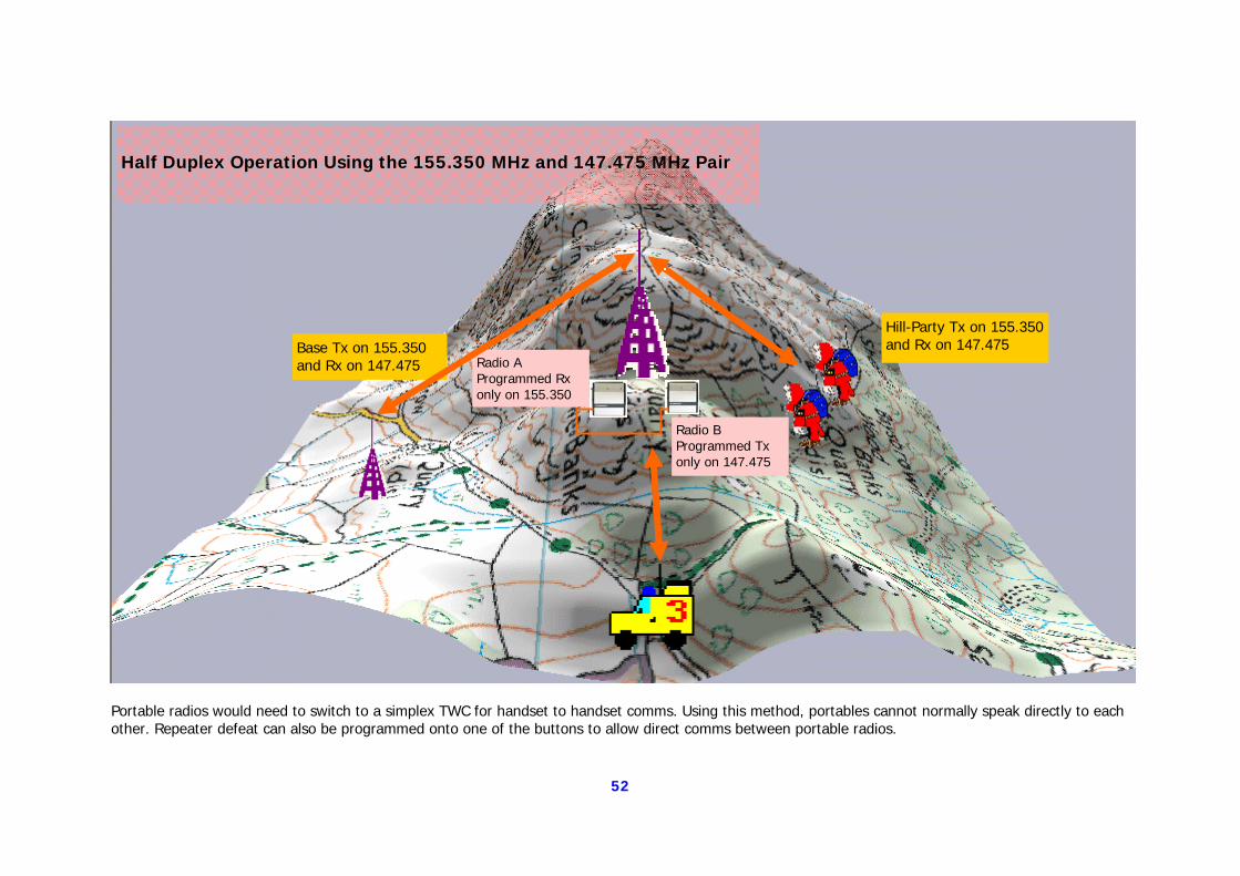
Radio A Programmed Rx only on 155.350
Radio B Programmed Tx only on 147.475
Base Tx on 155.350 and Rx on 147.475
Hill-Party Tx on 155.350 and Rx on 147.475
Half Duplex Operation Using the 155.350 MHz and 147.475 MHz Pair
Portable radios would need to switch to a simplex TWC for handset to handset comms. Using this method, portables cannot normally speak directly to each other. Repeater defeat can also be programmed onto one of the buttons to allow direct comms between portable radios.
53
That’s basically as far as the current design section goes. We haven’t covered everything that can be done and we probably never will but hopefully there’s enough information in these pages to help others gain the best from their systems or even to inspire someone to come up with a better one!
If that happens, I hope that you will send the details along so that we can share out the information
amongst all the teams.
All that remains is a section containing some general information and the contacts you need to speak to in order to get further information.
Summary and Additional Information
54
A Swift Summary A number of the circuits shown in this document are not really practical for reasons explained on that page, however, they would all work as rebroadcast devices as the fundamentals of operation are adhered to throughout. Two SRM9000 radios and a crossover cable. The idea is that practical circuits have been provided for those who can follow them and hopefully, enough detail is there to stimulate questions from those who can’t. The intention isn’t necessarily that anyone slavishly follows the circuit chosen although there’s nothing to stop you doing that if you wish. You will see from the diagrams that not all possible combinations have been described. Where I describe programming and a controlled relay, a dash-mounted switch can often be used instead. In most cases, you can use whichever method you prefer. As far as I can see, just about any combination of operational usage can be applied to any of the circuits. There are elements of programmed control and facilities, or selcall control, that can be used alongside a purely mechanical on/off arrangement. You can select the options you would like to use or the ones you think your team will be happy with, and speak to the person(s) responsible for that version for any details you need, or clarification as to whether some-thing different might work. There is now a lot of practical expertise available to us, we only have to make use of it. This document isn’t by any means definitive. It’s primary purpose is to show you what has been done with the equipment that, by and large, we already have. The level of complexity at which you decide to stop is up to your judgment of how it will be used by your team. None of the variations are necessarily ‘better’ than any other as they all use the same basic principle. In fact if you examine it very carefully, you’ll see that the fundamentally most important com-ponent in all the versions, is the cross-over cable consisting of seven wires and two plugs. Without one of these, none of the re-broadcast devices would work. Pick whichever one you think your team can operate and, between us all, we have the expertise available to get it going. Even all of this is only the beginning, Voice over Internet Provider (VoIP) is not only used to make telephone calls. Try looking at www.446user.co.uk and you will see that even the humble PMR446 radio with a nominal range of about 3 kilometres can be used to talk to anywhere in the world. Radio amateurs already use the ‘EchoLink’ and D-Star systems to do the same thing. Communications is changing rapidly and the days of the simple analogue radio may well be numbered. However, that day hasn’t arrived just yet and there’s still a lot that can be achieved if it’s not the rest of the world you want to talk to!
55
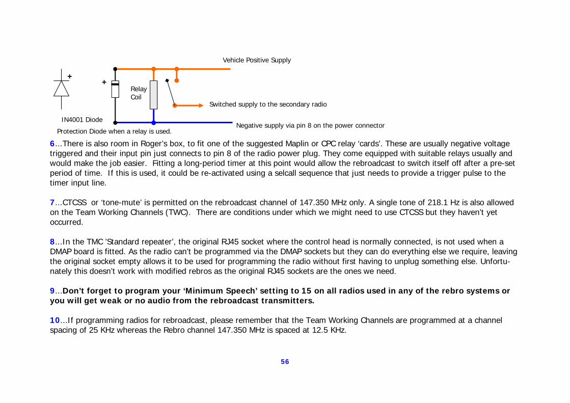
Notes and things to be aware of:- 1...The alternative front panel supplied with the DMAP board and carrying the 25 pin ‘D’ connector, does not need to be fitted if the facilities available on the 25-pin connector are not going to be used. Don’t fit the ribbon connection to the DMAP board and use the existing front panel by knocking out the pre-cut covers over the RJ45 connections. This takes up less space when you’re trying to sort all the connections out inside your vehicle. It also makes re-assembling the radio a lot easier as you don’t now have to stuff the 25 way ribbon cable inside. 2...The DMAP board can be fitted with a GPS receiver for those wishing to experiment with automatic vehicle location (AVL). No additional programming is necessary. The MA-ASIG board can also take a GPS and then becomes known as MA-ASIGF. Unfortu-nately the control head and the GPS both need the same serial port and the board only has one. However, if anyone intends to build up a GPS receiving system in their base then an MA-ASIG board without GPS will provide the necessary connection to the computer. DMAP boards are about four times the cost of an MA-ASIG board. An MA-ASIGF board can also be fitted to a vehicle to allow GPS tracking with a standard control head fitted. 3...If you are doing any modifications to the box containing the diplexer and aerial change-over relay, note that Roger Taylor who built them, fitted a drilled, Perspex spacer under the relay. This is because the screws used are slightly too long and without the spacer, will pass through the mounting plate and straight into the coil winding of the relay. Very bad. 4...If anyone wants to fit the suggested power relay to provide controlled switching of the secondary radio, Alan Prescott at Kes-wick fitted a small one inside the power plug shell, extremely elegant. You can also fit a larger one into the existing diplexer case alongside the aerial relay. 5...If the suggested circuit for the modified ‘Standard’ repeater is used, remember that a transistor switch has already been fitted to the aerial relay. In this configuration, it’s not necessary and can be removed with care. The pins it’s connected to are the ones you connect to the power plug pins 4 and 8. The relay should be fitted with a back-EMF prevention diode wired as shown in the diagram following. This stops the voltage generated by the collapsing magnetic field, when the relay is switched off, from blitzing your radio's sensitive parts. If you use a dash-mounted switch to provide power, you don’t need the diode.
56
6...There is also room in Roger’s box, to fit one of the suggested Maplin or CPC relay ‘cards’. These are usually negative voltage triggered and their input pin just connects to pin 8 of the radio power plug. They come equipped with suitable relays usually and would make the job easier. Fitting a long-period timer at this point would allow the rebroadcast to switch itself off after a pre-set period of time. If this is used, it could be re-activated using a selcall sequence that just needs to provide a trigger pulse to the timer input line. 7...CTCSS or ‘tone-mute’ is permitted on the rebroadcast channel of 147.350 MHz only. A single tone of 218.1 Hz is also allowed on the Team Working Channels (TWC). There are conditions under which we might need to use CTCSS but they haven’t yet occurred. 8...In the TMC ’Standard repeater’, the original RJ45 socket where the control head is normally connected, is not used when a DMAP board is fitted. As the radio can’t be programmed via the DMAP sockets but they can do everything else we require, leaving the original socket empty allows it to be used for programming the radio without first having to unplug something else. Unfortu-nately this doesn’t work with modified rebros as the original RJ45 sockets are the ones we need. 9...Don’t forget to program your ‘Minimum Speech’ setting to 15 on all radios used in any of the rebro systems or you will get weak or no audio from the rebroadcast transmitters. 10...If programming radios for rebroadcast, please remember that the Team Working Channels are programmed at a channel spacing of 25 KHz whereas the Rebro channel 147.350 MHz is spaced at 12.5 KHz.
IN4001 Diode
+ Relay Coil
Vehicle Positive Supply
Protection Diode when a relay is used.
Switched supply to the secondary radio
Negative supply via pin 8 on the power connector
+
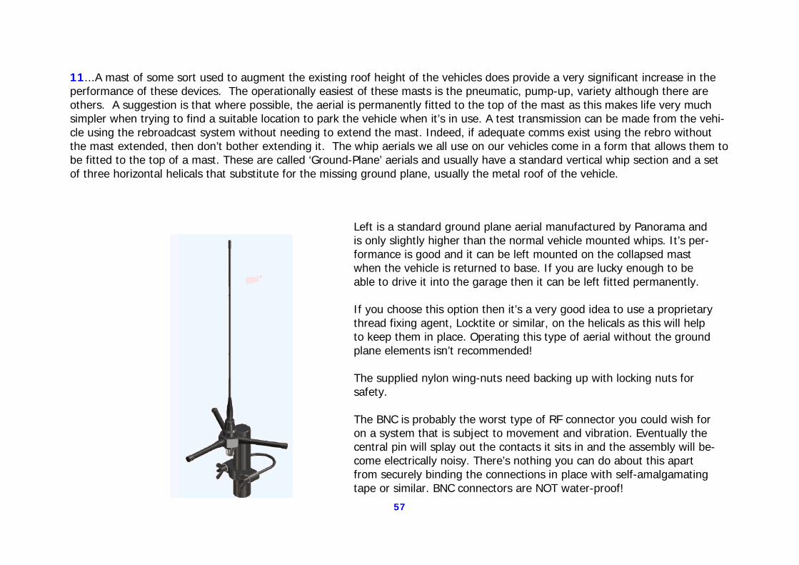
57
11...A mast of some sort used to augment the existing roof height of the vehicles does provide a very significant increase in the performance of these devices. The operationally easiest of these masts is the pneumatic, pump-up, variety although there are others. A suggestion is that where possible, the aerial is permanently fitted to the top of the mast as this makes life very much simpler when trying to find a suitable location to park the vehicle when it’s in use. A test transmission can be made from the vehi-cle using the rebroadcast system without needing to extend the mast. Indeed, if adequate comms exist using the rebro without the mast extended, then don’t bother extending it. The whip aerials we all use on our vehicles come in a form that allows them to be fitted to the top of a mast. These are called ‘Ground-Plane’ aerials and usually have a standard vertical whip section and a set of three horizontal helicals that substitute for the missing ground plane, usually the metal roof of the vehicle.
Left is a standard ground plane aerial manufactured by Panorama and is only slightly higher than the normal vehicle mounted whips. It’s per-formance is good and it can be left mounted on the collapsed mast when the vehicle is returned to base. If you are lucky enough to be able to drive it into the garage then it can be left fitted permanently. If you choose this option then it’s a very good idea to use a proprietary thread fixing agent, Locktite or similar, on the helicals as this will help to keep them in place. Operating this type of aerial without the ground plane elements isn’t recommended! The supplied nylon wing-nuts need backing up with locking nuts for safety. The BNC is probably the worst type of RF connector you could wish for on a system that is subject to movement and vibration. Eventually the central pin will splay out the contacts it sits in and the assembly will be-come electrically noisy. There’s nothing you can do about this apart from securely binding the connections in place with self-amalgamating tape or similar. BNC connectors are NOT water-proof!
58
12...Although there have been no instances reported of this happening, a problem that can occur with repeaters built along these lines is that both transmitters lock in transmit mode simultaneously. This causes permanent ‘dead-keying’ on both frequencies and will badly effect your comms! A crude but effective way of making sure this doesn’t happen, is to fit a single, 8 to10 Amp, self-resetting fuse in the supply line. If both transmitters switch to transmit at the same time, the current required will exceed the capacity of the fuse and it will blow so switching them off. A little while latter, it will reset itself and if the problem has cleared, then all is well and operation will con-tinue as normal. 13...Although the cross-over cable is a standard part available from Team Simoco, it can also be made up by you if required. The positioning of the two radios may actually dictate this as the cable comes in only one size. The maximum length you can make them up in is about 3 metres but at this length, screened CAT5 cable should be used along with ferrite EMI filters where possible. 14...The terms ‘Rebroadcast’ and ‘Repeater’ are used almost interchangeably in this document. In fact a UKSAR ‘convention’ is be-coming established where ‘Rebroadcast’ refers to the two-frequency-simplex system adopted by the Lake District and it’s near neighbours. Whereas ‘Repeater’ is now more often used to refer to the wide area duplex system used by some teams. This latter system is where the radios receive and transmit on different frequencies and normal simplex (back-to-back) operation is not possi-ble. Strictly then, our system as used in the examples in this document, should be called ‘Rebroadcast’. 15...The Simoco radio model immediately before the SRM9000 series was the PRM8010/20 series. A number of teams still have these radios and they are still good, workhorse sets. It’s possible using a small external circuit, to set up repeaters using these radios. If anyone wants details, contact Rob Brookes (details at the back) and I’ll send them to you. 16...Due to the fact that the architecture of the SRM9000 vehicle radios is very similar to that of the SRP9100 handsets, I asked TMC if it would be possible to make repeaters using these handsets. The answer is basically, ‘Yes’, but the handsets are not in-tended for this use where the vehicle sets are. As such a couple of small differences exist that, in theory, could be overcome ex-ternally so making this possible. I will take this one up with TMC and see if we can get some practical instruction as to how this might be done. 17… If you are setting up two SRM9000 radios for use as a rebroadcast system even if one of them is also going to do service as your vehicle’s main comms radio, the ‘Mute Speaker During FFSK’ option must NOT be checked. Doing so will prevent the data
59
getting through the system altogether. It will also, fairly obviously, result in the received data being heard in all it’s glory by the vehicle radio. That, for the time being, is something we have to live with I’m afraid.
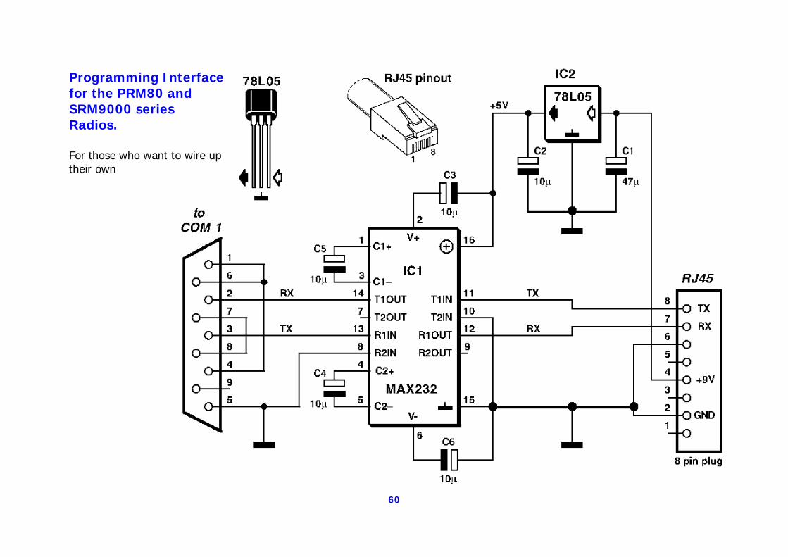
60
Programming Interface for the PRM80 and SRM9000 series Radios. For those who want to wire up their own
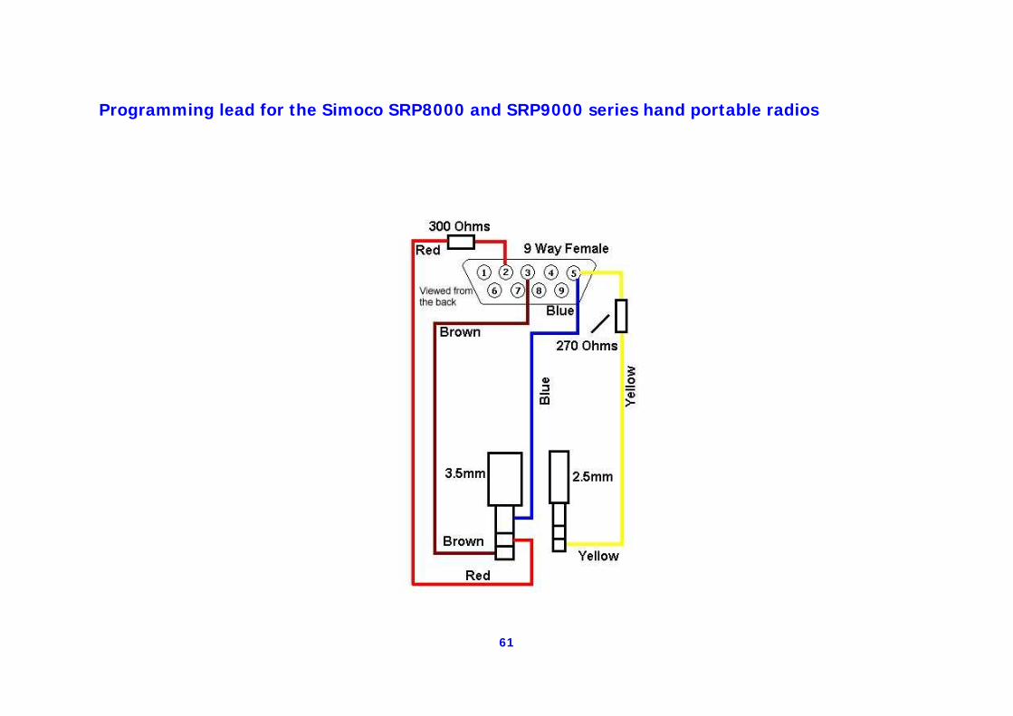
61
Programming lead for the Simoco SRP8000 and SRP9000 series hand portable radios
62
General information regarding this document:- ‘Simple’ and modified ‘Standard’ repeaters. PRM80 repeaters (See ‘Notes’) Remote channel-changing fixed repeater Rob Brookes LDSAMRA Comms Projects Officer [email protected] 01539 728684
Component suppliers and information suggestions:- Team Simoco Ltd:- Andy Gamble Business Development Manager Mobile: 07710 738171 DDI: 01332 375591 Fax: 01332 375501 E-mail: [email protected] www.teamsimoco.co.uk TMC Radio Pty Ltd:- www.tmcradio.com CPC Preston:- http://cpc.farnell.com/jsp/home/homepage.jsp [email protected] Maplin Electronics:- www.maplin.co.uk RadioSpares:- www.radiospares.co.uk Panorama Antennas Ltd:- www.panorama.co.uk ATDI Radio Propagation Plots www.atdi.co.uk Roger Taylor, Tower Communications Customisation of the Diplexers. 01353 749859
Contacts :-
‘Simple’ repeater Stewart Devlin Coniston MRT [email protected] telephone 015394-37273
‘Simple’ and ‘Standard’ Repeaters Portable use of the ‘Simple’ repeater Iain Nicholson Bowland Pennine MRT [email protected]
Enhanced software and selcall control of all repeaters Dave Binks Duddon & Furness MRT [email protected]
Operation using aerial separation rather than diplexers Selcall control of ‘Standard’ repeater Modified ‘Standard’ Repeater Alan Prescott Keswick MRT [email protected]
Operational use of the repeaters in the Borders James Coles Moffatt MRT 01387 251 083 [email protected]
MRMap Development Team 10/01/2009
MRMap - www.mrmap.org.uk
MRMap-GPS-Tracking-Communications-Safety-Mountain Rescue-Mapping-Downloads-Free Software
Silent GPS Data Reception on a Simplex Voice Channel
Silent GPS Data Reception on a Simplex Voice Channel.
A Guide for Team Communications and Training Officers.
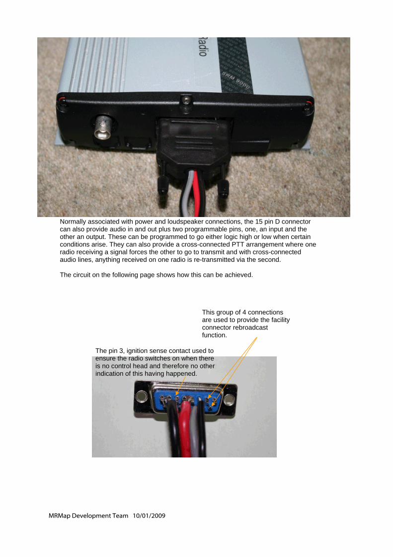
MRMap Development Team 10/01/2009
Normally associated with power and loudspeaker connections, the 15 pin D connector can also provide audio in and out plus two programmable pins, one, an input and the other an output. These can be programmed to go either logic high or low when certain conditions arise. They can also provide a cross-connected PTT arrangement where one radio receiving a signal forces the other to go to transmit and with cross-connected audio lines, anything received on one radio is re-transmitted via the second. The circuit on the following page shows how this can be achieved.
This group of 4 connections are used to provide the facility connector rebroadcast function.
The pin 3, ignition sense contact used to ensure the radio switches on when there is no control head and therefore no other indication of this having happened.
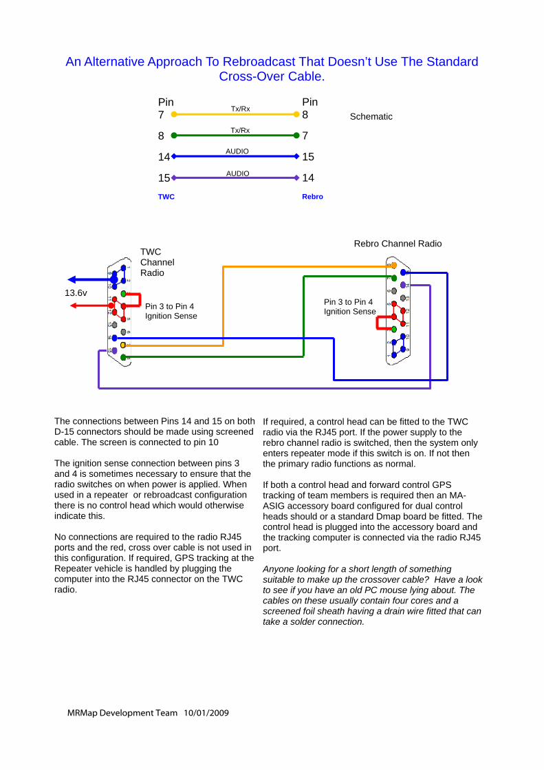
MRMap Development Team 10/01/2009
TWC Channel Radio
Pin 3 to Pin 4 Ignition Sense
Pin 3 to Pin 4 Ignition Sense
Rebro Channel Radio
The connections between Pins 14 and 15 on both D-15 connectors should be made using screened cable. The screen is connected to pin 10 The ignition sense connection between pins 3 and 4 is sometimes necessary to ensure that the radio switches on when power is applied. When used in a repeater or rebroadcast configuration there is no control head which would otherwise indicate this. No connections are required to the radio RJ45 ports and the red, cross over cable is not used in this configuration. If required, GPS tracking at the Repeater vehicle is handled by plugging the computer into the RJ45 connector on the TWC radio.
If required, a control head can be fitted to the TWC radio via the RJ45 port. If the power supply to the rebro channel radio is switched, then the system only enters repeater mode if this switch is on. If not then the primary radio functions as normal. If both a control head and forward control GPS tracking of team members is required then an MA-ASIG accessory board configured for dual control heads should or a standard Dmap board be fitted. The control head is plugged into the accessory board and the tracking computer is connected via the radio RJ45 port. Anyone looking for a short length of something suitable to make up the crossover cable? Have a look to see if you have an old PC mouse lying about. The cables on these usually contain four cores and a screened foil sheath having a drain wire fitted that can take a solder connection.
Pin 7 8 14 15 TWC
Pin 8 7 15 14 Rebro
Tx/Rx
Tx/Rx
AUDIO
AUDIO
An Alternative Approach To Rebroadcast That Doesn’t Use The Standard Cross-Over Cable.
Schematic
13.6v
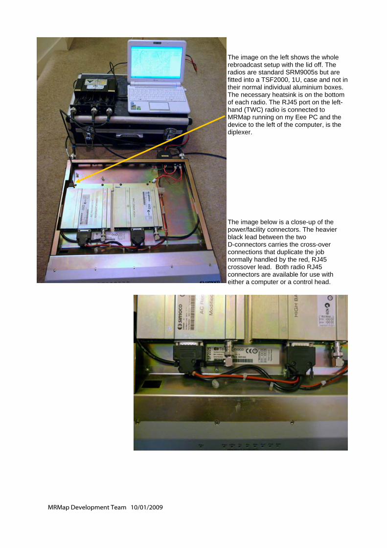
MRMap Development Team 10/01/2009
The image on the left shows the whole rebroadcast setup with the lid off. The radios are standard SRM9005s but are fitted into a TSF2000, 1U, case and not in their normal individual aluminium boxes. The necessary heatsink is on the bottom of each radio. The RJ45 port on the left-hand (TWC) radio is connected to MRMap running on my Eee PC and the device to the left of the computer, is the diplexer. The image below is a close-up of the power/facility connectors. The heavier black lead between the two D-connectors carries the cross-over connections that duplicate the job normally handled by the red, RJ45 crossover lead. Both radio RJ45 connectors are available for use with either a computer or a control head.
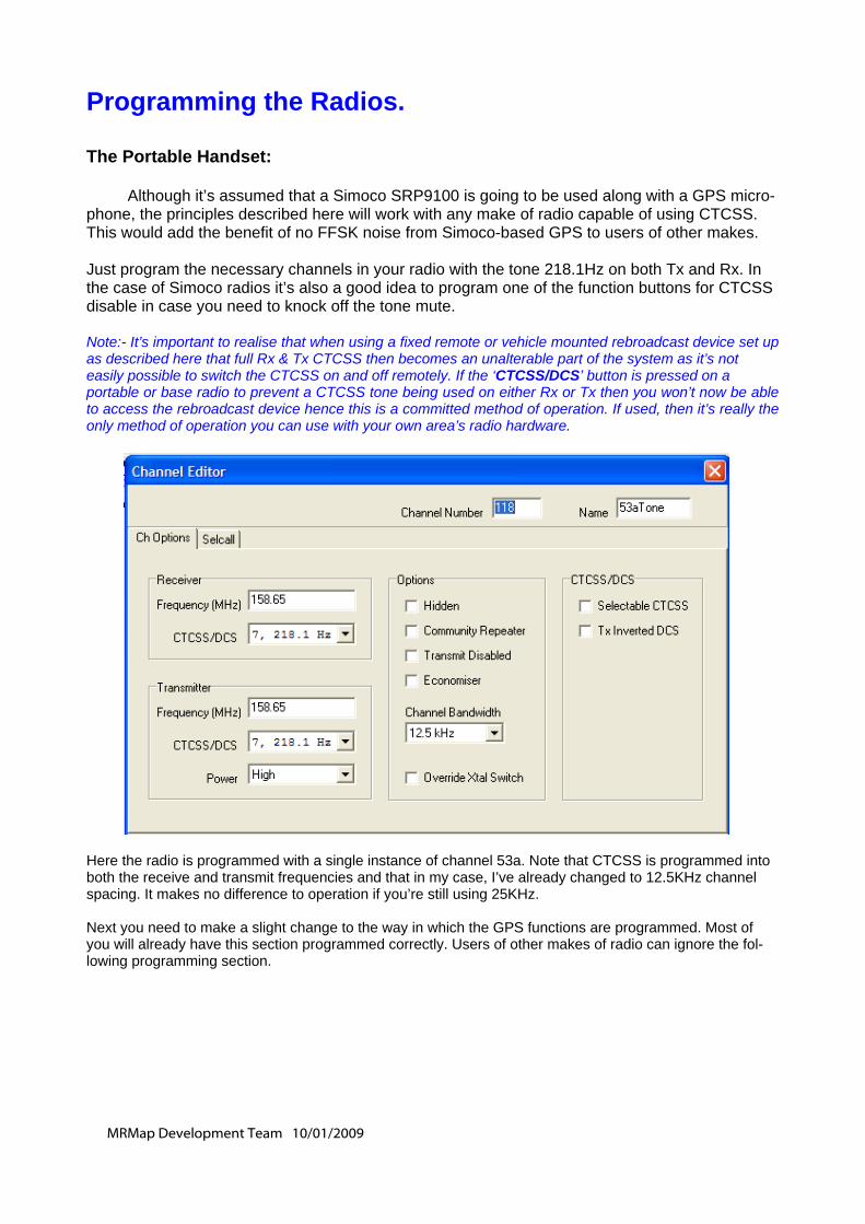
MRMap Development Team 10/01/2009
Programming the Radios. The Portable Handset: Although it’s assumed that a Simoco SRP9100 is going to be used along with a GPS micro-phone, the principles described here will work with any make of radio capable of using CTCSS. This would add the benefit of no FFSK noise from Simoco-based GPS to users of other makes. Just program the necessary channels in your radio with the tone 218.1Hz on both Tx and Rx. In the case of Simoco radios it’s also a good idea to program one of the function buttons for CTCSS disable in case you need to knock off the tone mute. Note:- It’s important to realise that when using a fixed remote or vehicle mounted rebroadcast device set up as described here that full Rx & Tx CTCSS then becomes an unalterable part of the system as it’s not easily possible to switch the CTCSS on and off remotely. If the ‘CTCSS/DCS’ button is pressed on a portable or base radio to prevent a CTCSS tone being used on either Rx or Tx then you won’t now be able to access the rebroadcast device hence this is a committed method of operation. If used, then it’s really the only method of operation you can use with your own area’s radio hardware. Here the radio is programmed with a single instance of channel 53a. Note that CTCSS is programmed into both the receive and transmit frequencies and that in my case, I’ve already changed to 12.5KHz channel spacing. It makes no difference to operation if you’re still using 25KHz. Next you need to make a slight change to the way in which the GPS functions are programmed. Most of you will already have this section programmed correctly. Users of other makes of radio can ignore the fol-lowing programming section.
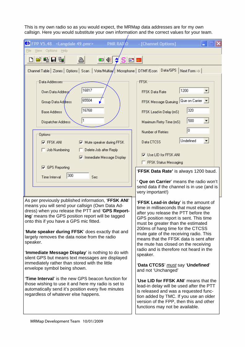
MRMap Development Team 10/01/2009
This is my own radio so as you would expect, the MRMap data addresses are for my own callsign. Here you would substitute your own information and the correct values for your team.
As per previously published information, ‘FFSK ANI’ means you will send your callsign (Own Data Ad-dress) when you release the PTT and ‘GPS Report-ing’ means the GPS position report will be tagged onto this if you have a GPS mic fitted. ‘Mute speaker during FFSK’ does exactly that and largely removes the data noise from the radio speaker. ‘Immediate Message Display’ is nothing to do with silent GPS but means text messages are displayed immediately rather than stored with the little envelope symbol being shown. ‘Time Interval’ is the new GPS beacon function for those wishing to use it and here my radio is set to automatically send it’s position every five minutes regardless of whatever else happens.
‘FFSK Data Rate’ is always 1200 baud. ‘ Que on Carrier’ means the radio won’t send data if the channel is in use (and is very important!) ‘FFSK Lead-in delay’ is the amount of time in milliseconds that must elapse after you release the PTT before the GPS position report is sent. This time must be greater than the estimated 200ms of hang time for the CTCSS mute gate of the receiving radio. This means that the FFSK data is sent after the mute has closed on the receiving radio and is therefore not heard in the speaker. ‘Data CTCSS’ must say ‘Undefined’ and not ‘Unchanged’ ‘Use LID for FFSK ANI’ means that the lead-in delay will be used after the PTT is released and was a requested func-tion added by TMC. If you use an older version of the FPP, then this and other functions may not be available.
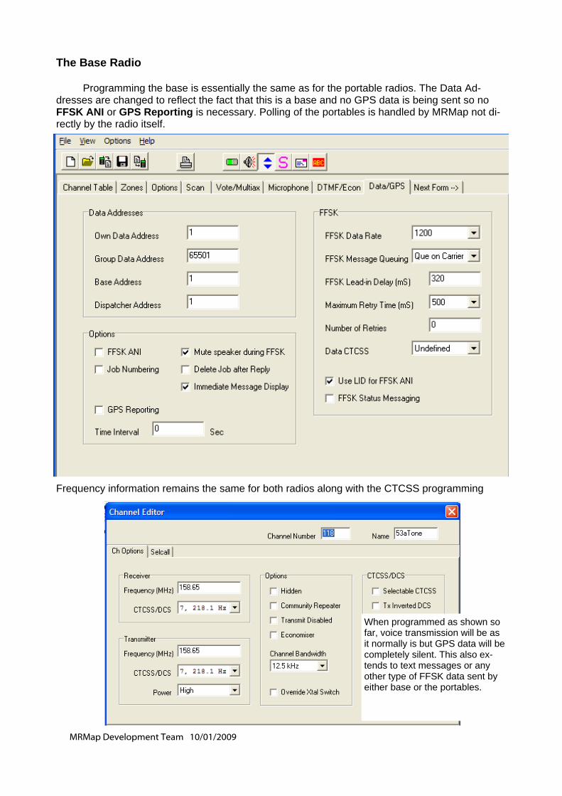
MRMap Development Team 10/01/2009
The Base Radio Programming the base is essentially the same as for the portable radios. The Data Ad-dresses are changed to reflect the fact that this is a base and no GPS data is being sent so no FFSK ANI or GPS Reporting is necessary. Polling of the portables is handled by MRMap not di-rectly by the radio itself.
Frequency information remains the same for both radios along with the CTCSS programming
When programmed as shown so far, voice transmission will be as it normally is but GPS data will be completely silent. This also ex-tends to text messages or any other type of FFSK data sent by either base or the portables.
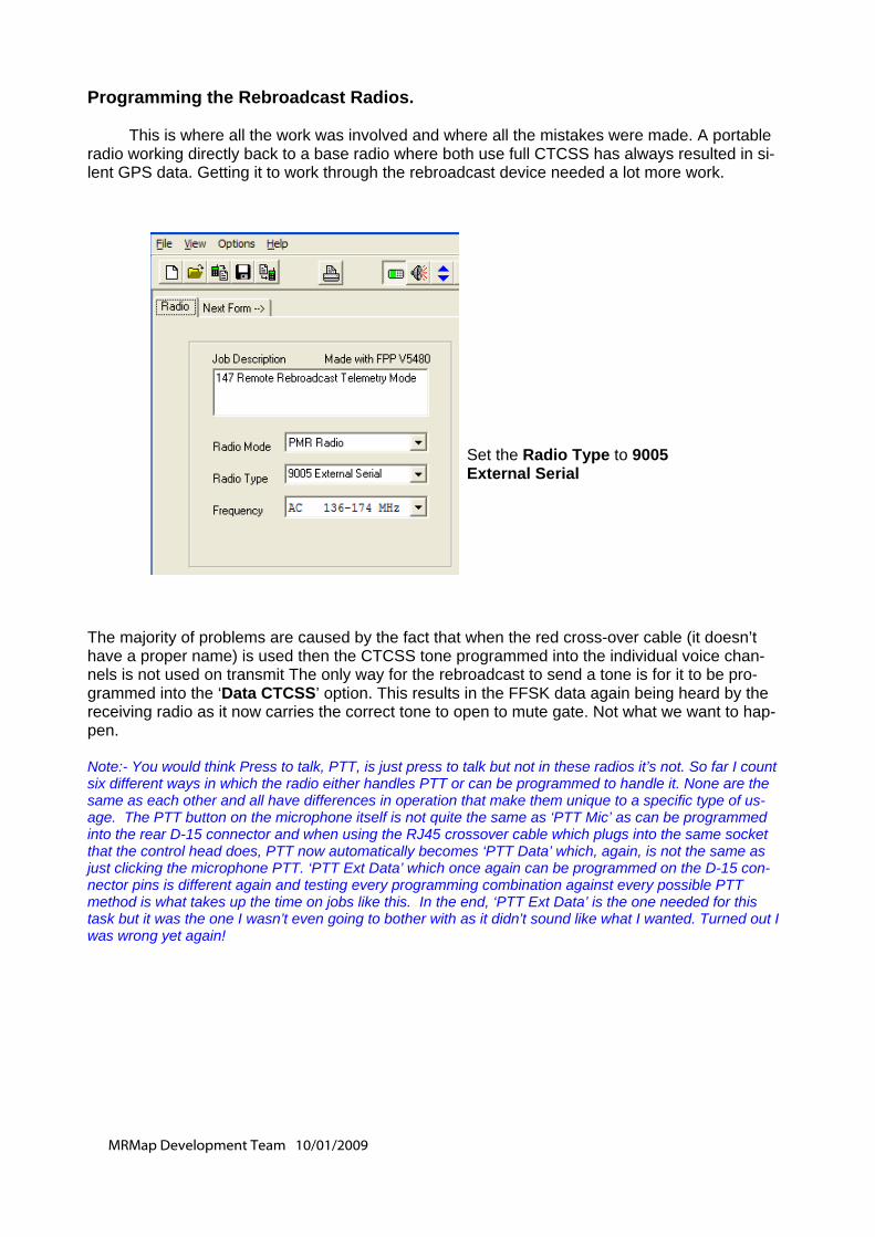
MRMap Development Team 10/01/2009
Programming the Rebroadcast Radios. This is where all the work was involved and where all the mistakes were made. A portable radio working directly back to a base radio where both use full CTCSS has always resulted in si-lent GPS data. Getting it to work through the rebroadcast device needed a lot more work. The majority of problems are caused by the fact that when the red cross-over cable (it doesn’t have a proper name) is used then the CTCSS tone programmed into the individual voice chan-nels is not used on transmit The only way for the rebroadcast to send a tone is for it to be pro-grammed into the ‘Data CTCSS’ option. This results in the FFSK data again being heard by the receiving radio as it now carries the correct tone to open to mute gate. Not what we want to hap-pen. Note:- You would think Press to talk, PTT, is just press to talk but not in these radios it’s not. So far I count six different ways in which the radio either handles PTT or can be programmed to handle it. None are the same as each other and all have differences in operation that make them unique to a specific type of us-age. The PTT button on the microphone itself is not quite the same as ‘PTT Mic’ as can be programmed into the rear D-15 connector and when using the RJ45 crossover cable which plugs into the same socket that the control head does, PTT now automatically becomes ‘PTT Data’ which, again, is not the same as just clicking the microphone PTT. ‘PTT Ext Data’ which once again can be programmed on the D-15 con-nector pins is different again and testing every programming combination against every possible PTT method is what takes up the time on jobs like this. In the end, ‘PTT Ext Data’ is the one needed for this task but it was the one I wasn’t even going to bother with as it didn’t sound like what I wanted. Turned out I was wrong yet again!
Set the Radio Type to 9005 External Serial
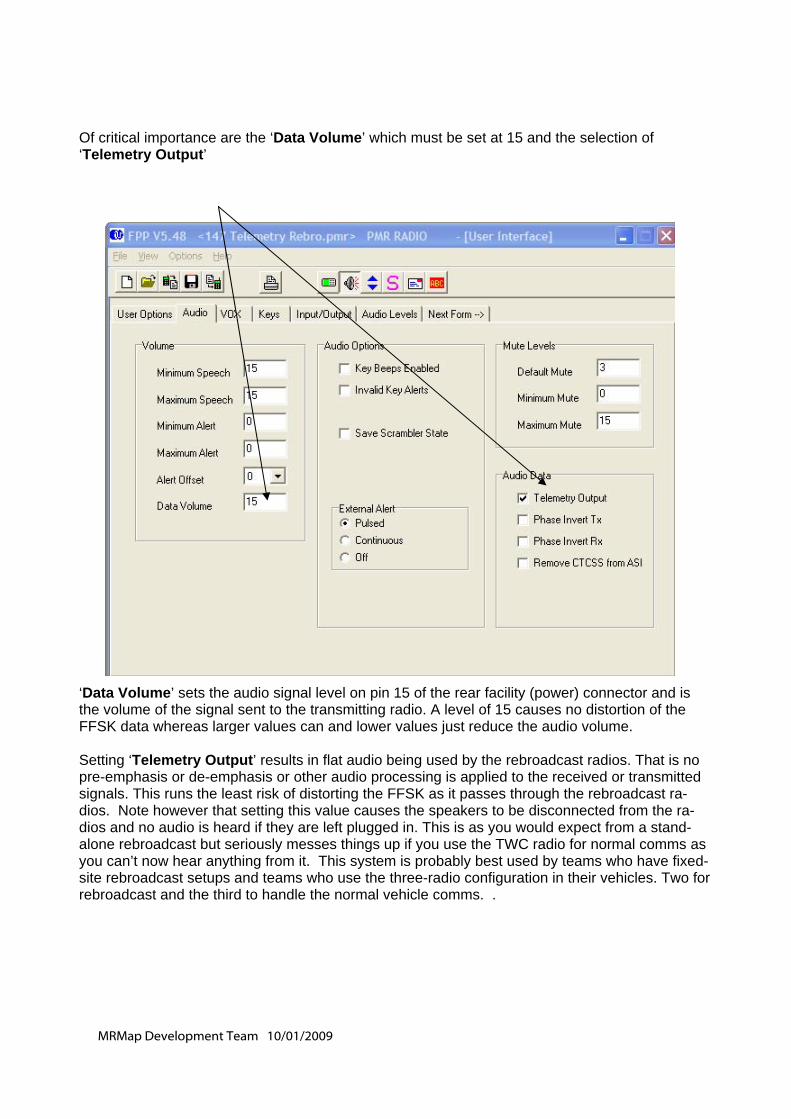
MRMap Development Team 10/01/2009
Of critical importance are the ‘Data Volume’ which must be set at 15 and the selection of ‘Telemetry Output’
‘Data Volume’ sets the audio signal level on pin 15 of the rear facility (power) connector and is the volume of the signal sent to the transmitting radio. A level of 15 causes no distortion of the FFSK data whereas larger values can and lower values just reduce the audio volume. Setting ‘Telemetry Output’ results in flat audio being used by the rebroadcast radios. That is no pre-emphasis or de-emphasis or other audio processing is applied to the received or transmitted signals. This runs the least risk of distorting the FFSK as it passes through the rebroadcast ra-dios. Note however that setting this value causes the speakers to be disconnected from the ra-dios and no audio is heard if they are left plugged in. This is as you would expect from a stand-alone rebroadcast but seriously messes things up if you use the TWC radio for normal comms as you can’t now hear anything from it. This system is probably best used by teams who have fixed-site rebroadcast setups and teams who use the three-radio configuration in their vehicles. Two for rebroadcast and the third to handle the normal vehicle comms. .
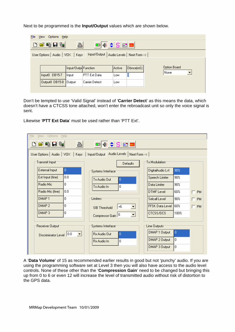
MRMap Development Team 10/01/2009
Next to be programmed is the Input/Output values which are shown below. Don’t be tempted to use ‘Valid Signal’ instead of ‘Carrier Detect’ as this means the data, which doesn’t have a CTCSS tone attached, won’t enter the rebroadcast unit so only the voice signal is sent. Likewise ‘PTT Ext Data’ must be used rather than ‘PTT Ext’.
A ‘Data Volume’ of 15 as recommended earlier results in good but not ‘punchy’ audio. If you are using the programming software set at Level 3 then you will also have access to the audio level controls. None of these other than the ‘Compression Gain’ need to be changed but bringing this up from 0 to 6 or even 12 will increase the level of transmitted audio without risk of distortion to the GPS data.
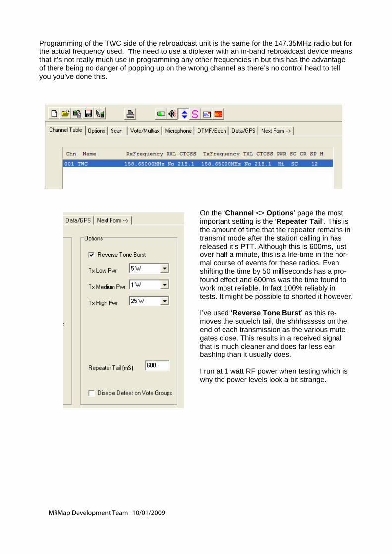
MRMap Development Team 10/01/2009
Programming of the TWC side of the rebroadcast unit is the same for the 147.35MHz radio but for the actual frequency used. The need to use a diplexer with an in-band rebroadcast device means that it’s not really much use in programming any other frequencies in but this has the advantage of there being no danger of popping up on the wrong channel as there’s no control head to tell you you’ve done this.
On the ‘Channel <> Options’ page the most important setting is the ‘Repeater Tail’. This is the amount of time that the repeater remains in transmit mode after the station calling in has released it’s PTT. Although this is 600ms, just over half a minute, this is a life-time in the nor-mal course of events for these radios. Even shifting the time by 50 milliseconds has a pro-found effect and 600ms was the time found to work most reliable. In fact 100% reliably in tests. It might be possible to shorted it however. I’ve used ‘Reverse Tone Burst’ as this re-moves the squelch tail, the shhhssssss on the end of each transmission as the various mute gates close. This results in a received signal that is much cleaner and does far less ear bashing than it usually does. I run at 1 watt RF power when testing which is why the power levels look a bit strange.
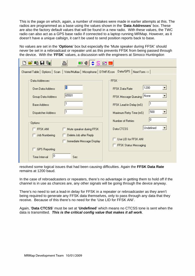
MRMap Development Team 10/01/2009
This is the page on which, again, a number of mistakes were made in earlier attempts at this. The radios are programmed as a base using the values shown in the ‘Data Addresses’ box. These are also the factory default values that will be found in a new radio. With these values, the TWC radio can also act as a GPS base radio if connected to a laptop running MRMap. However, as it doesn’t have a unique callsign, it can’t be used to send position reports back to base. No values are set in the ‘Options’ box but especially the ‘Mute speaker during FFSK’ should never be set in a rebroadcast or repeater unit as this prevents FFSK from being passed through the device. With the ‘FFSK’ values, a discussion with the engineers at Simoco Huntingdon
resolved some logical issues that had been causing difficulties. Again the FFSK Data Rate remains at 1200 baud. In the case of rebroadcasters or repeaters, there’s no advantage in getting them to hold off if the channel is in use as chances are, any other signals will be going through the device anyway. There’s no need to set a lead-in delay for FFSK in a repeater or rebroadcaster as they aren’t being required to generate any FFSK data themselves, only to pass through any data that they receive. Because of this there’s no need for the ‘Use LID for FFSK ANI’. Again, ‘Data CTCSS’ must be set at ‘Undefined’ which means no CTCSS tone is sent when the data is transmitted. This is the critical config value that makes it all work.
MRMap Development Team 10/01/2009
Summary: The system described here has been run at full power around the Kendal area. I have an antenna at both ends of the house roof for testing things like this and the 147MHz link was only transmit-ting down the length of the house. However the TWC radio was required to operate to a moving vehicle several miles away and no polls or replies were missed. All the types of polling of GPS equipped radios was tried and several handsets were operated alongside the rebroadcast unit. Not all of these were SRP9100s or indeed, Simoco radios and in none of them was the FFSK data audible when CTCSS was enabled on receive and transmit. All received data, be that at the ‘base’ end or in the vehicle itself, was completely silent but voice transmissions were received normally although the usual squelch tail was thankfully absent. The amount of wiring needed in the power/facility connectors is not great and is easily done by anyone who can wield a soldering iron. This can be taken a stage further if required as LED op-eration indicators can be wired to the same pin 8 and ground. Still to do: Firstly I need to check that the same system also works with a cross band rebroadcast unit. (Done) Next, will it work with an SRM-based, duplex repeater as against a rebroadcaster? Hopefully finally, I need to re-introduce the ability to change channel in the cross band rebroad-cast. This is lost due to the absence of the red crossover lead in this system. However, TMC in Australia advise me that the rear, facility connector PTT lines take precedence over the RJ45 crossover cable. The audio connections on the RJ45 X-over cable are not required and can be left out as can all the other connections on this cable except those on pins 1 and 2. These two are the data connections that handle the remote channel changing instructions in a cross-band re-broadcast. Unfortunately they are also the connections that handle PTT when this cable is used to facilitate rebroadcast or repeater operation, however, TMC did say that the rear facility connector takes PTT precedence. So far I don’t know whether this is correct but as soon as I’ve wired up a quick two-wire cable (!) I’ll give it a go. (Done) One last thing, even though the FFSK speaker mute on Simoco radios does satisfactorily remove 90% of the data noise, it’s still very weird to see the plot move or watch ‘GPS Poll’ come up on the radio display but to hear absolutely, and that really is absolutely, nothing. For ten years now I’ve been listening to radios beep away at me and now it’s gone, I quite miss it.
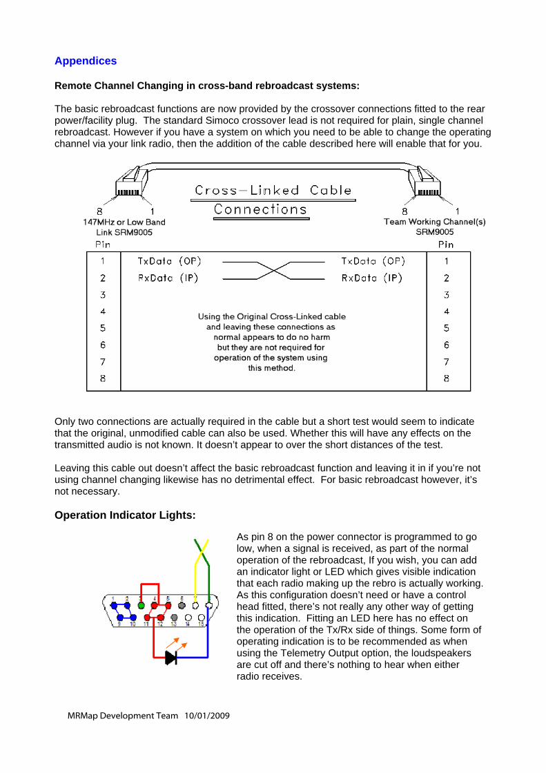
MRMap Development Team 10/01/2009
Appendices Remote Channel Changing in cross-band rebroadcast systems: The basic rebroadcast functions are now provided by the crossover connections fitted to the rear power/facility plug. The standard Simoco crossover lead is not required for plain, single channel rebroadcast. However if you have a system on which you need to be able to change the operating channel via your link radio, then the addition of the cable described here will enable that for you.
Only two connections are actually required in the cable but a short test would seem to indicate that the original, unmodified cable can also be used. Whether this will have any effects on the transmitted audio is not known. It doesn’t appear to over the short distances of the test. Leaving this cable out doesn’t affect the basic rebroadcast function and leaving it in if you’re not using channel changing likewise has no detrimental effect. For basic rebroadcast however, it’s not necessary. Operation Indicator Lights:
As pin 8 on the power connector is programmed to go low, when a signal is received, as part of the normal operation of the rebroadcast, If you wish, you can add an indicator light or LED which gives visible indication that each radio making up the rebro is actually working. As this configuration doesn’t need or have a control head fitted, there’s not really any other way of getting this indication. Fitting an LED here has no effect on the operation of the Tx/Rx side of things. Some form of operating indication is to be recommended as when using the Telemetry Output option, the loudspeakers are cut off and there’s nothing to hear when either radio receives.
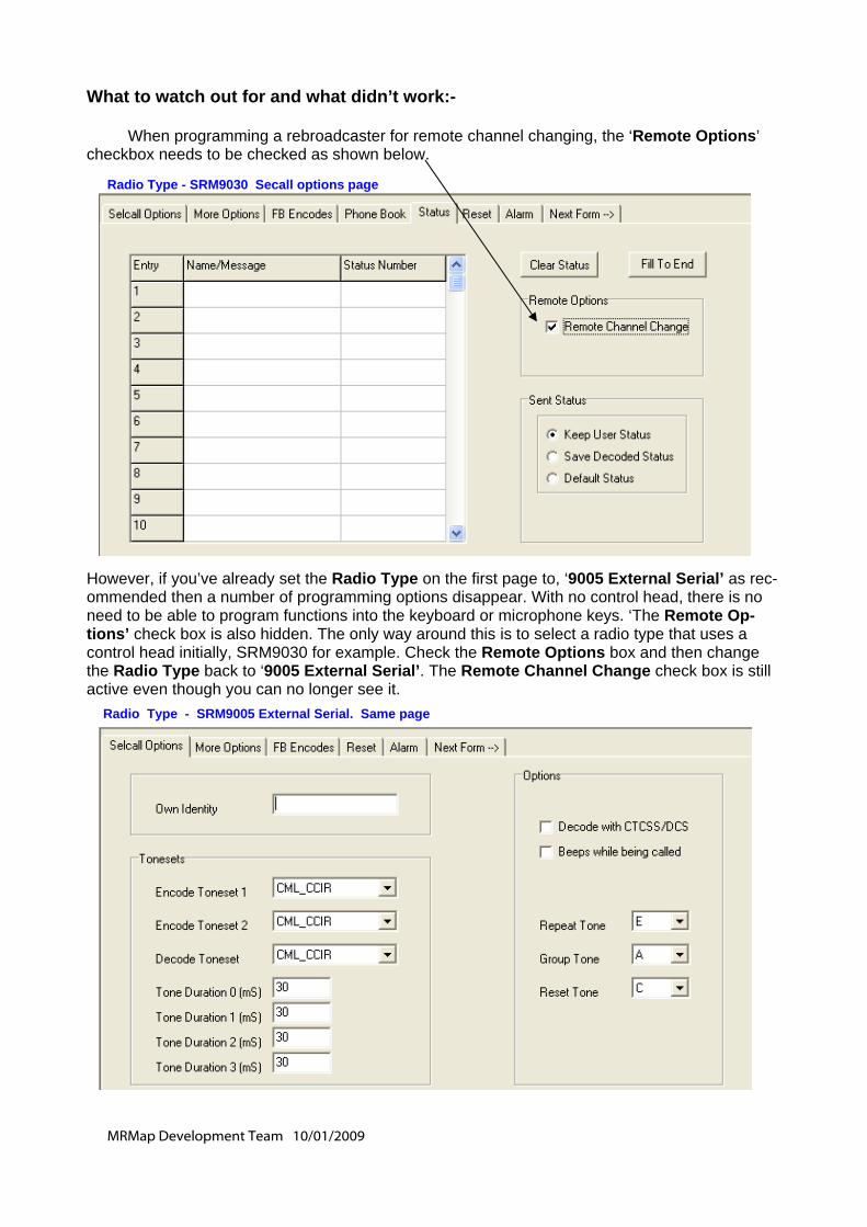
MRMap Development Team 10/01/2009
What to watch out for and what didn’t work:- When programming a rebroadcaster for remote channel changing, the ‘Remote Options’ checkbox needs to be checked as shown below.
However, if you’ve already set the Radio Type on the first page to, ‘9005 External Serial’ as rec-ommended then a number of programming options disappear. With no control head, there is no need to be able to program functions into the keyboard or microphone keys. ‘The Remote Op-tions’ check box is also hidden. The only way around this is to select a radio type that uses a control head initially, SRM9030 for example. Check the Remote Options box and then change the Radio Type back to ‘9005 External Serial’. The Remote Channel Change check box is still active even though you can no longer see it.
Radio Type - SRM9030 Secall options page
Radio Type - SRM9005 External Serial. Same page
MRMap Development Team 10/01/2009
One where I’ve so far failed miserably is putting a single selcall tone onto the end of the transmis-sion made by the rebroadcast radios so as to act as an indication that you are still within range of base. This is sometimes called a ‘Comfort Tone’. I couldn’t get a tone at all from either of the rebro radios using ‘PTT Data Ext’. It would seem from trying all the others that only the actual microphone PTT button can initiate the sending of the ‘PTT Off’ selcall tone. As a way around this I tried adding the tone to the end of the base transmission as it’s passed straight through the rebro and, sure enough, if the microphone PTT was pressed then a tone was sent. However under these circumstances you would already know that you were still within range of base as you would then hear them speak. What’s needed is a tone at the end of the otherwise silent, automatic group poll sent out by MRMap. This I couldn’t achieve but I’ll keep on trying until I’m sure it can or can’t be done. I did get some odd delay effects under certain circumstances but not an actual tone so it may be some setting I have wrong (again!) Unfortunately, doing it this way adds yet more time to the operation cycle of the rebro and there is already a short but notice-able period after a handset transmits, when it can’t open the rebro receiver for a second or two. I also need to look at this. If anyone wants to help with the selcall tone testing, please feel free! Still left To Do:- Just whether it will work with a duplex wide area repeater really. The rest is just tidying up and refining the timing values. As so far described it will work and will probably be suitable for those who just want to mute out the FFSK data noise. As and if I refine any of the config values, I’ll update this document on the blog page and on the documents download page of the MRMap website.