Embed Size (px)
Citation preview

Software Requirements Specification
Page 1
SimCity Civil Development Tool:
Build-It Buffalo
Team 44:
Arpita Venkanna Belagur Danny Peng
Brandon Carr Ramya Rao
Chaitanya Choudhary Nettem Roy Joo
Ching Hua Chang Siddhant Rane

Software Requirements Specification
Page 2
Table of Contents
1. Introduction to Functional Requirements .................................................................................................... 4
1.1 Map Module .................................................................................................................................................................. 6
1.2 Routing Module .......................................................................................................................................................... 7
1.3 Cost Calculator ............................................................................................................................................................ 8
1.4 User Authentication Module .............................................................................................................................. 6
1.5 Tutorial Module.......................................................................................................................................................... 7
1.6 Toolbar Module .......................................................................................................................................................... 5
1.7 Chat Module.................................................................................................................................................................. 5
2. Functional Requirements ........................................................................................................................................ 6
2.1 Level 1 SABD: General Layout and Legend ............................................................................................... 6
2.2 Level 2 SABD - Database Layer ......................................................................................................................... 7
2.3 Level 3 SABD – Graphical Assets Database Module ............................................................................. 8
2.4 Level 3 SABD – Map & Building Database Modules ............................................................................. 9
2.5 Level 3 SABD – User Directory & User Authentication Database Modules ........................ 10
2.6 Level 3 SABD – API Layer .................................................................................................................................. 11
2.7 Level 3 SABD – API Layer – Tablet/Mobile API Module.......................................................... 12,15
2.8 Level 3 SABD – API Layer – PC API Module ........................................................................................... 13
2.9 Level 3 SABD – Client Layer............................................................................................................................. 14
2.7 Level 3 SABD – API Layer – Tablet/Mobile API Module.......................................................... 12,15

Software Requirements Specification
Page 3
3. Sample Screens ........................................................................................................................................................... 16
3.1 UI Component........................................................................................................................................................... 16
3.2 Toolbar ......................................................................................................................................................................... 17
3.2.1 Chat Box ................................................................................................................................................................... 17
3.2.2 Main Toolbox ........................................................................................................................................................ 17
3.3 View ................................................................................................................................................................................ 18
3.4 Search ............................................................................................................................................................................ 19
4. Managing Changes .................................................................................................................................................... 20
5. Cross Reference Listing.......................................................................................................................................... 21
6. Integration Thread.................................................................................................................................................... 22
6.1 Diagram ........................................................................................................................................................................ 22

Software Requirements Specification
Page 4
1. Introduction to Functional Requirements
1.1 Map Module The system offers a map feature to show the entire city of buffalo in two modes: edit
mode and view mode. Within these modes, various functionalities exist to allow the user
greater control over his or her map. These features mimic pre-existing mapping
applications, such as the ability to rotate between different viewpoints, such as 2D,
Isometric and Street View.
In addition, the user will have the ability to drag and drop objects such as stop signs,
traffic lights, and common city structures like parks, buildings, etc. on the map in edit mode.
The map module will also include an option to toggle the level of complexity of the
graphical user interface to cater to each individual and will provide detailed information on
city buildings (size, location, cost of construction, etc.); these points of information are
available on the map on zoom in.
1.2 Routing Module This module deals with calculating the shortest path possible between two locations
in Buffalo. This module also enables user to find an address in Buffalo.
1.3 Cost Calculator This functionality estimates the cost of the user’s model based on real world estimates.
This is mainly helpful for the user in competitions which restrict the amount a user can
spend for creating the model.
1.4 User Authentication Module The login details of users are captured in the database. There are three types of
users: Tourists, Residents of Buffalo and NGOs (non-governmental organizations), and
Government Officials and City Architects.
Only government officials and city architects have complete access to the database.
They have the permission to plug in the latest updates and arrange competitions. Each
user’s individual contribution to a work in progress is saved and associated with the
corresponding login.
1.5 Tutorial Module A simple demo of the web application will be part of this module. The various tools
available in the application and their functions will be elaborated. This will be made
available to all users.

Software Requirements Specification
Page 5
1.6 Toolbar Module This will be a drag and drop interface provided to the user to work on a project.
Some of the features include stop signs, traffic lights, parks, hospitals, schools, roads and
other basic city building blocks. Each of these blocks is associated with a base price
required to build it.
1.7 Chat Module Several users of the application working on a single project would find this feature
particularly useful. Non-profit organizations will be able to collaborate on their ideas and
build on a project.

Software Requirements Specification
Page 6
2. Functional Requirements
2.1 Level 1 SABD – General Layout and Legend
Note: The most abstract overview of the system, as described within modules. The
most general level is 1; more specific levels will go one level higher. The system is split into
four different layers, each separated by either a hardware or software difference. The data
is hosted within the database layer and is utilized in the API layer; finally, the API layer’s
functionality is viewed within the client layer’s interfaces on either PC or tablet.

Software Requirements Specification
Page 7
2.2 Level 2 SABD - Database Layer
Note: The above picture depicts one level deeper into the database manager system.
It shows what it is composed of and what it is dependent upon. The database patch
management module is the updater, as the application is intended to be updated
constantly. The modules in blue represent database modules that interact via the DMS.
Software Requirements Specification
Page 8
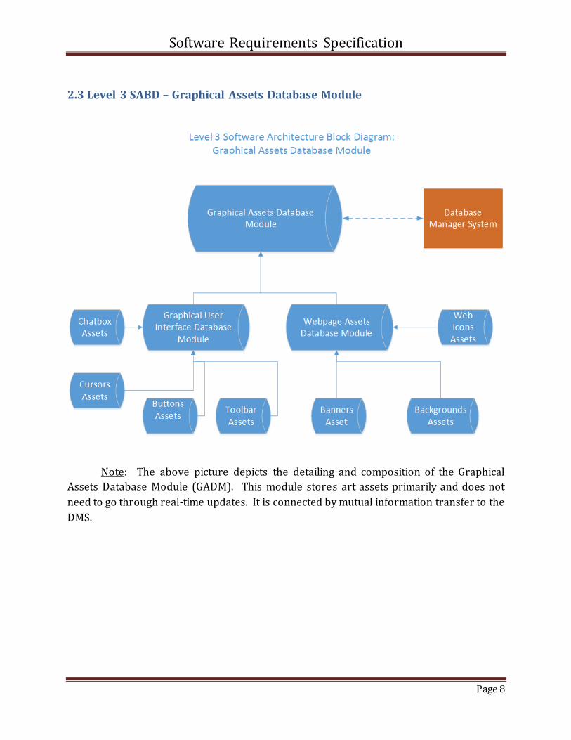
2.3 Level 3 SABD – Graphical Assets Database Module
Note: The above picture depicts the detailing and composition of the Graphical
Assets Database Module (GADM). This module stores art assets primarily and does not
need to go through real-time updates. It is connected by mutual information transfer to the
DMS.
Software Requirements Specification
Page 9
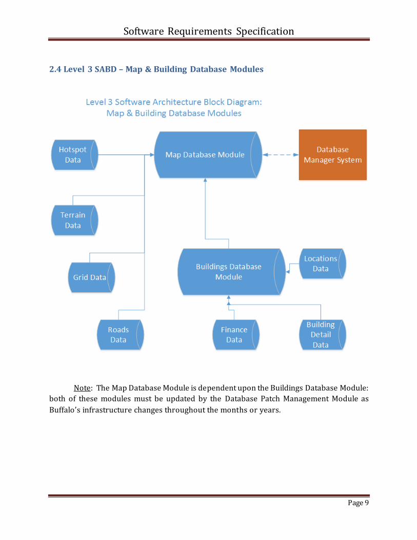
2.4 Level 3 SABD – Map & Building Database Modules
Note: The Map Database Module is dependent upon the Buildings Database Module:
both of these modules must be updated by the Database Patch Management Module as
Buffalo’s infrastructure changes throughout the months or years.
Software Requirements Specification
Page 10
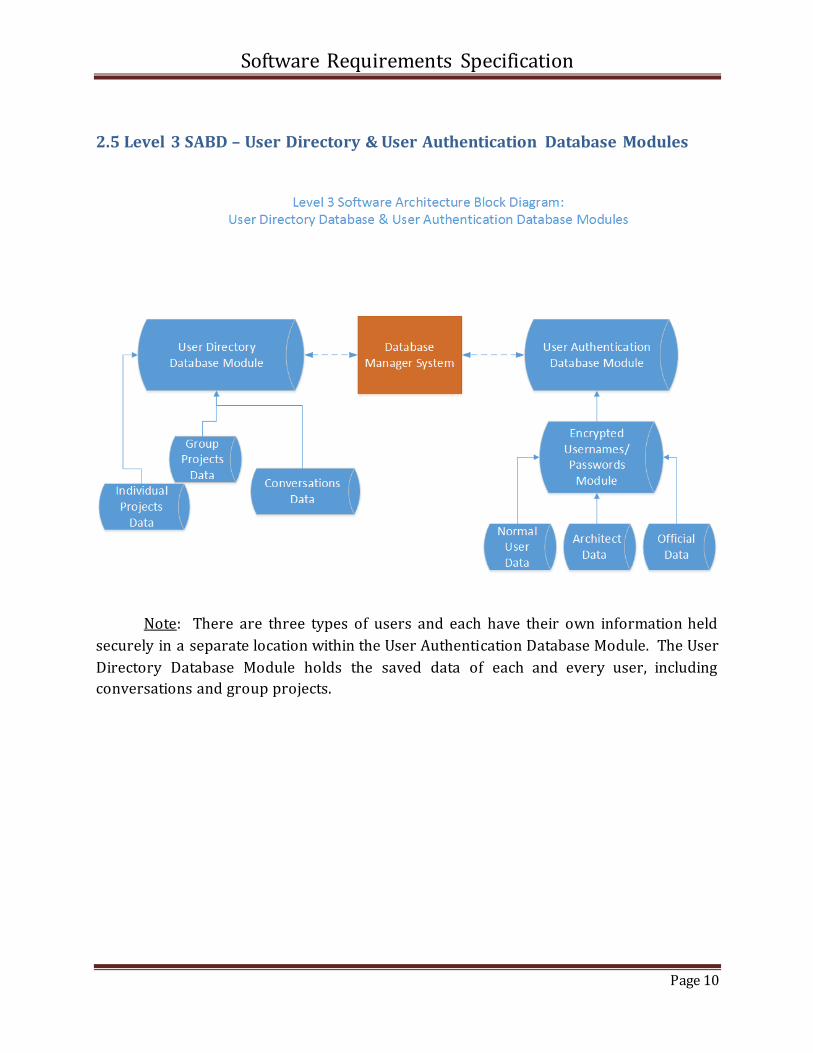
2.5 Level 3 SABD – User Directory & User Authentication Database Modules
Note: There are three types of users and each have their own information held
securely in a separate location within the User Authentication Database Module. The User
Directory Database Module holds the saved data of each and every user, including
conversations and group projects.

Software Requirements Specification
Page 11
2.6 Level 3 SABD – API Layer
Note: The above picture shows that through the application server, the database
modules are able to directly communicate and transfer information to the
PC/Mobile/Tablet API’s.

Software Requirements Specification
Page 12
2.7 Level 3 SABD – API Layer – Tablet/Mobile API Module

Software Requirements Specification
Page 13
2.8 Level 3 SABD – API Layer – PC API Module

Software Requirements Specification
Page 14
2.9 Level 3 SABD – Client Layer
Note: The Build and Remove modules also include cost calculation: how much
financial worth a building consists of. These financial projections are created from modern
statistics of real estate prices and allow the user to work under a certain bound. These
modules are developed separately from the functionalities within the API Managers.

Software Requirements Specification
Page 15
Note for Tablet/Mobile API: The API includes functionality nearly identical to that
of the PC API. Some features are altered in scope, such as the Toolbar Module and Traffic
Module, due to the limitations that mobile devices hold in comparison to a PC.

Software Requirements Specification
Page 16
3. Sample Screens
3.1 UI Component
We decided to go a little crazy with the home screen just to attract people. We agree
that when a user logs into a website he should understand what the site does. The HOME
PAGE tries to answer these questions and pique their interest. When a user clicks on the
button for the first time, we present a tutorial which explains different parts of the UI.
We provide a basic drag and drop functionality so that everyone can try to design
and implement their ideas. We already discussed how important it is for a user to be able to
achieve something in a short time easily to capture his interest. Let’s check out the first UI
screen and find out what components we have.

Software Requirements Specification
Page 17
3.2 Toolbar The basic tool bar that every person who has ever used a browser or any basic
editing application is familiar with where you simply save your file, edit it, view an old file,
use the help feature or select different tools. The idea is that the project is never saved on
the user’s computer but simply because it takes up space and could be given an option. The
project by default will be saved in a format where only changes are recorded and saved in
our database but we keep this complexity hidden from the user.
3.2.1 Chat Box There are projects where people could work as part of a team and communication
would be essential. We decided to have a chat box for the same. Most websites today have a
chat box for interacting with other users with similar interests and this feature should be
useful to many people. In case a user doesn’t want a chat box he can simply close it.
3.2.2 Main Toolbox The main toolbox allows users to choose what they want to add. If the wish to
destroy something, the tools option will have a destroy mouse or right click would provide
one. For adding new structures we click on one of the main options like the house icon and
a new toolbar expands showing what structures lie within that option. For example the
structure option would have hospitals, gas stations, different houses, schools etc.
We also have various options within the main tool bar like structures, signs, tree s, roads of
different types, or the option to plain a mountain or a region to create something new or
simply to find out costs.
Software Requirements Specification
Page 18
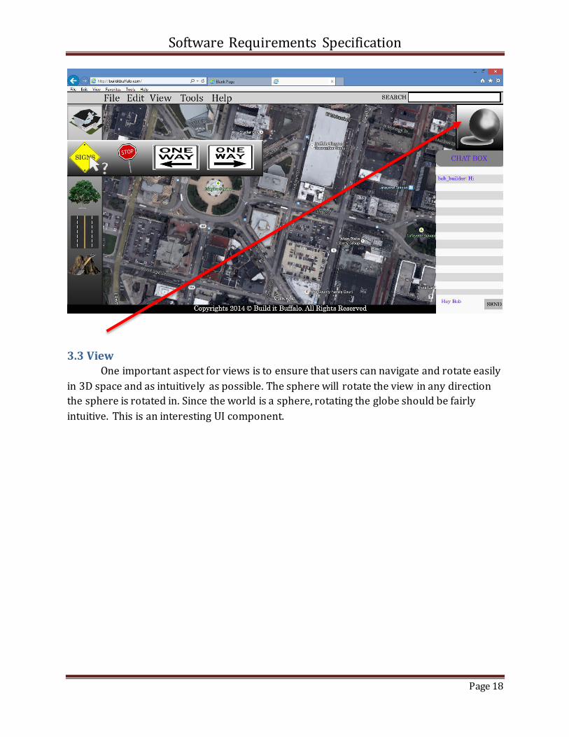
3.3 View One important aspect for views is to ensure that users can navigate and rotate easily
in 3D space and as intuitively as possible. The sphere will rotate the view in any direction
the sphere is rotated in. Since the world is a sphere, rotating the globe should be fairly
intuitive. This is an interesting UI component.

Software Requirements Specification
Page 19
3.4 Search
Another interesting feature is the search component. It is understandable that
navigating through toolbars to find something specific could be tedious and time
consuming. For making this efficient a user can simply type what he’s looking for and as
shown in the above image, the user can just drag the hospital structure into the city map.
Zooming can be done with the mouse scroll or hitting CTRL and these features will be a
part of the tutorial.

Software Requirements Specification
Page 20
4. Managing Changes
Name: ______________________________ Department: ____________________ Date: ____________
Phone: ( ) - ____ - ______ Office/Room Number: _____________ Hours: ________________________
Category of Change (Check a category and circle the corresponding sub-category):
__ Database Layer: (1) Mainframe Module (2) Patch Management
Module
__ Server Layer: (1) Application Server
__ API Layer: (1) Smartphone/Tablet Module (2) PC Module
__ Client Layer: (1) Mobile Client UI (2) PC Client UI
Summary (Write a description of the change):
_____________________________________________________________________________________
_____________________________________________________________________________________
_____________________________________________________________________________________
_____________________________________________________________________________________
Estimated Cost: _________________ Urgency: Mild / Moderate / Severe
Check all that apply:
__ Affects user data
__ Affects chat functionality
__ Affects account creation/management
__ Affects graphics rendering
__ Requires new hardware
__ Requires new artistic assets
__ Requires new music/sound assets

Software Requirements Specification
Page 21
5. Cross Reference Listing
Individual Capabilities of End System
Location in System Specification
Location in Software Requirements Specification
User Login System 4.3 2.5
Mapping & Navigation System
4.3 2.4
Building Objects & Placing on Map
4.3 2.9
Functional Graphical User Interface
3 2.3
User Profile System 5 2.5
Data Updating System 6.1 2.2
Chatting/Collaborating Functionality
4.2, 4.3 2.9
Viewing Hotspot Feature 3 2.7, 2.8
Routing Shortest Path Feature
3 2.7, 2.8
Cost Calculation Feature 3 2.9
Saving Projects Feature 3 2.7, 2.8

Software Requirements Specification
Page 22
6. Integration Thread
6.1 Diagram
The integration thread is essentiality, a skeleton structure formed by critical modules.
An integration thread needs to be minimal and only include the bare necessities for the
system to function. The core modules in the Build-It Buffalo system are the Database
Layer, the basic graphical assets and the web server. The Database layer can include the
basic types of data that would need to be store such as Terrain, Roads and Buildings.
If the customer asks for more information to be stored in those databases (such as the
amount of floors for a building), it could cause trouble but it is necessary to implement the
databases during our initial pass so that we can go on to testing the core functionality. All
the graphical assets function singularly and do not interact with each other, allowing us to
implement them without the fear of having to remodel them if the user adds changes to the
requirements, although the GUI might have to be redone.
The renderer for Build-It Buffalo is imperative to initial testing so it must be included in
the integration thread. After all the modules in the integration thread are done being
implemented, it is the best time to test and start looking for customer modifications.


![BuildIT 2015, Tallinn2015.buildit-tallinn.eu/wp-content/uploads/2015/03/5... · 2015. 5. 3. · [Dow Corning: Silicone Structural Glazing Manual] 23.04.15 Bonding of Glass –Felix](https://img.pdfslide.us/doc/110x75/60aa1ac15842fd28eb68f038/buildit-2015-2015-5-3-dow-corning-silicone-structural-glazing-manual-230415.jpg)