Embed Size (px)
Citation preview

SIMATIC TI545/TI555
System Manual
Order Number: PPX:545/555–8101–2Manual Assembly Number: 2586546–0084Second Edition

Copyright 1994 by Siemens Industrial Automation, Inc. All Rights Reserved — Printed in USA
Reproduction, transmission or use of this document or contents is not permitted without express consent ofSiemens Industrial Automation, Inc. All rights, including rights created by patent grant or registration of a utility model ordesign, are reserved.
Since Siemens Industrial Automation, Inc. does not possess full access to data concerning all of the uses and applicationsof customer’s products, we do not assume responsibility either for customer product design or for any infringements ofpatents or rights of others which may result from our assistance.
Technical data is subject to change.
We check the contents of every manual for accuracy at the time it is approved for printing; however, there may beundetected errors. Any errors found will be corrected in subsequent editions. Any suggestions for improvement arewelcomed.

MANUAL PUBLICATION HISTORY
SIMATIC TI545/TI555 System ManualOrder Manual Number: PPX:545/555–8101-2Refer to this history in all correspondence and/or discussion about this manual.
Event Date Description
Original Issue 02/93 Original Issue (2801030-0001)Second Edition 10/94 Second Edition (2801030-0002)
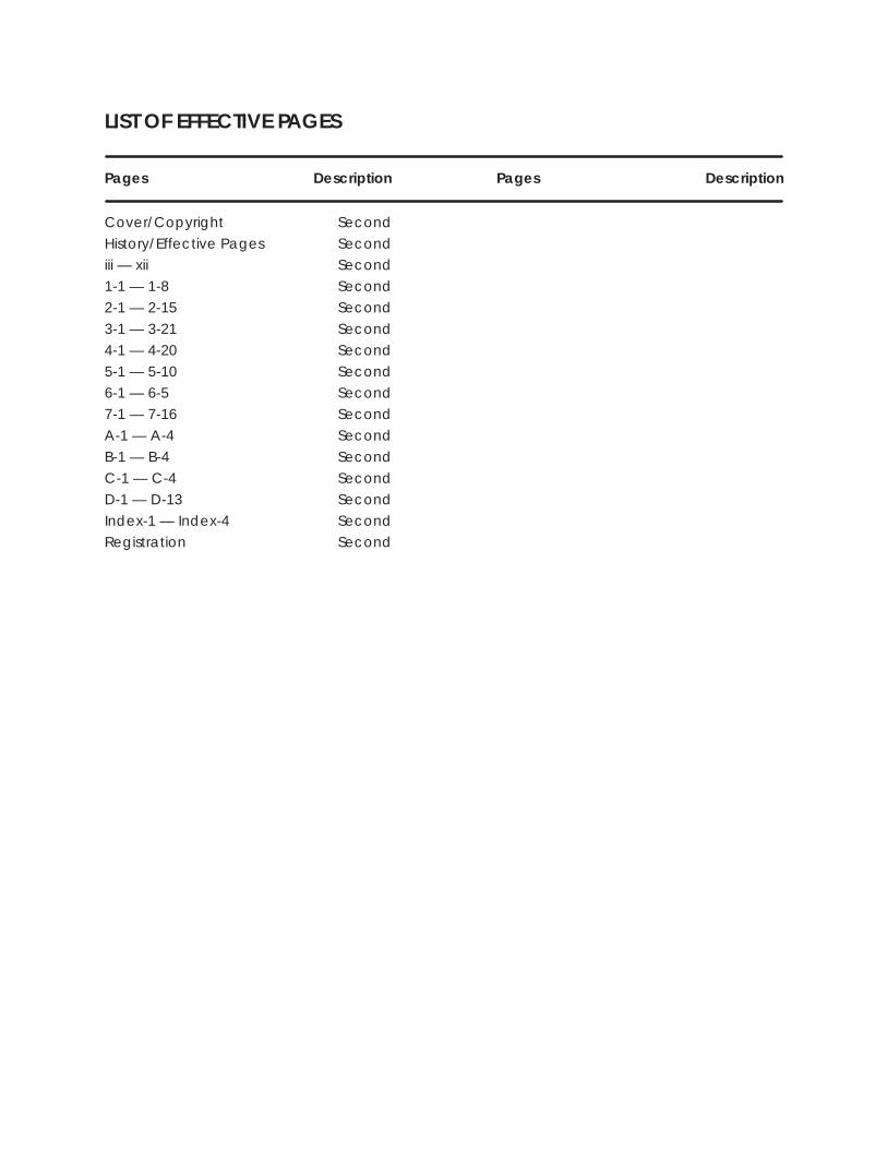
LIST OF EFFECTIVE PAGES
Pages Description Pages Description
Cover/Copyright SecondHistory/Effective Pages Secondiii — xii Second1-1 — 1-8 Second2-1 — 2-15 Second
3-1 — 3-21 Second4-1 — 4-20 Second5-1 — 5-10 Second6-1 — 6-5 Second7-1 — 7-16 SecondA-1 — A-4 Second
B-1 — B-4 SecondC-1 — C-4 SecondD-1 — D-13 SecondIndex-1 — Index-4 SecondRegistration Second
Contents iii
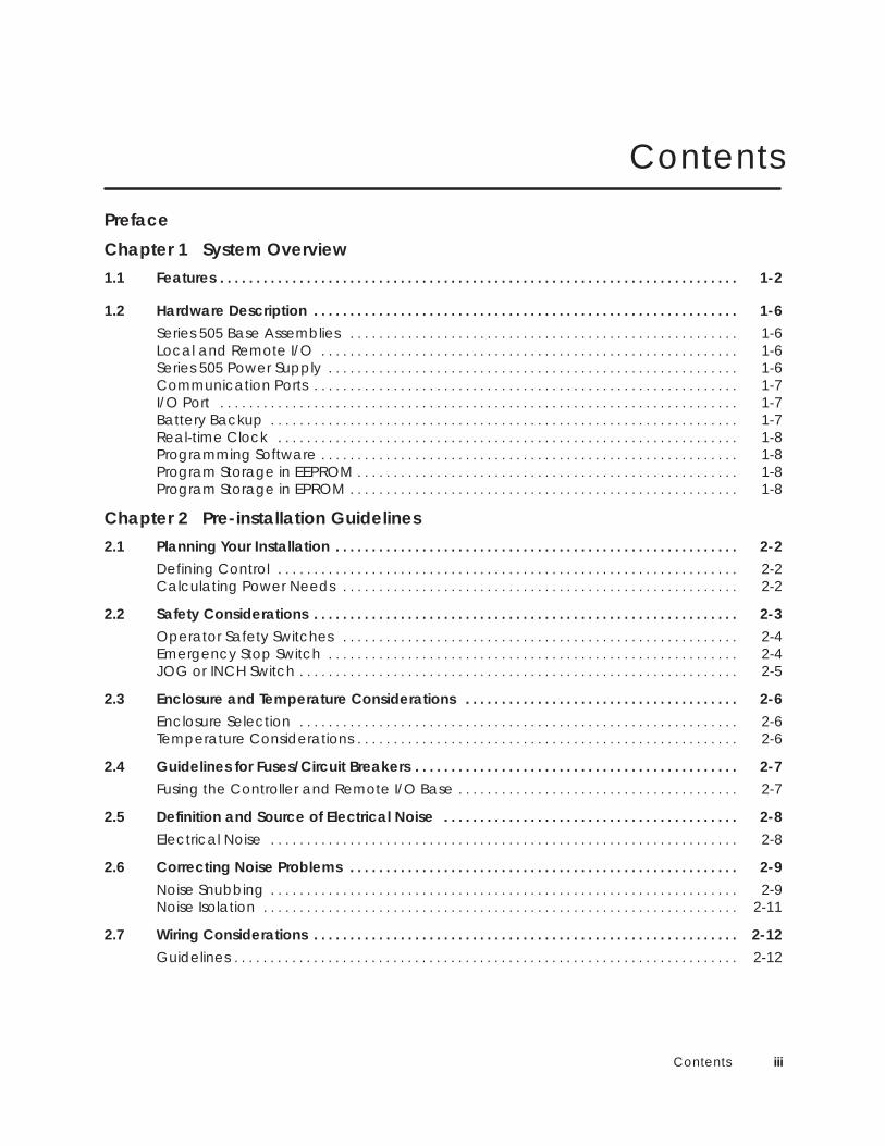
Contents
Preface
Chapter 1 System Overview1.1 Features 1-2. . . . . . . . . . . . . . . . . . . . . . . . . . . . . . . . . . . . . . . . . . . . . . . . . . . . . . . . . . . . . . . . . . . . . . . .
1.2 Hardware Description 1-6. . . . . . . . . . . . . . . . . . . . . . . . . . . . . . . . . . . . . . . . . . . . . . . . . . . . . . . . . . . Series 505 Base Assemblies 1-6. . . . . . . . . . . . . . . . . . . . . . . . . . . . . . . . . . . . . . . . . . . . . . . . . . . . . . Local and Remote I/O 1-6. . . . . . . . . . . . . . . . . . . . . . . . . . . . . . . . . . . . . . . . . . . . . . . . . . . . . . . . . . Series 505 Power Supply 1-6. . . . . . . . . . . . . . . . . . . . . . . . . . . . . . . . . . . . . . . . . . . . . . . . . . . . . . . . . Communication Ports 1-7. . . . . . . . . . . . . . . . . . . . . . . . . . . . . . . . . . . . . . . . . . . . . . . . . . . . . . . . . . . I/O Port 1-7. . . . . . . . . . . . . . . . . . . . . . . . . . . . . . . . . . . . . . . . . . . . . . . . . . . . . . . . . . . . . . . . . . . . . . . . Battery Backup 1-7. . . . . . . . . . . . . . . . . . . . . . . . . . . . . . . . . . . . . . . . . . . . . . . . . . . . . . . . . . . . . . . . . Real-time Clock 1-8. . . . . . . . . . . . . . . . . . . . . . . . . . . . . . . . . . . . . . . . . . . . . . . . . . . . . . . . . . . . . . . . Programming Software 1-8. . . . . . . . . . . . . . . . . . . . . . . . . . . . . . . . . . . . . . . . . . . . . . . . . . . . . . . . . . Program Storage in EEPROM 1-8. . . . . . . . . . . . . . . . . . . . . . . . . . . . . . . . . . . . . . . . . . . . . . . . . . . . . Program Storage in EPROM 1-8. . . . . . . . . . . . . . . . . . . . . . . . . . . . . . . . . . . . . . . . . . . . . . . . . . . . . .
Chapter 2 Pre-installation Guidelines2.1 Planning Your Installation 2-2. . . . . . . . . . . . . . . . . . . . . . . . . . . . . . . . . . . . . . . . . . . . . . . . . . . . . . . .
Defining Control 2-2. . . . . . . . . . . . . . . . . . . . . . . . . . . . . . . . . . . . . . . . . . . . . . . . . . . . . . . . . . . . . . . . Calculating Power Needs 2-2. . . . . . . . . . . . . . . . . . . . . . . . . . . . . . . . . . . . . . . . . . . . . . . . . . . . . . .
2.2 Safety Considerations 2-3. . . . . . . . . . . . . . . . . . . . . . . . . . . . . . . . . . . . . . . . . . . . . . . . . . . . . . . . . . . Operator Safety Switches 2-4. . . . . . . . . . . . . . . . . . . . . . . . . . . . . . . . . . . . . . . . . . . . . . . . . . . . . . . Emergency Stop Switch 2-4. . . . . . . . . . . . . . . . . . . . . . . . . . . . . . . . . . . . . . . . . . . . . . . . . . . . . . . . . JOG or INCH Switch 2-5. . . . . . . . . . . . . . . . . . . . . . . . . . . . . . . . . . . . . . . . . . . . . . . . . . . . . . . . . . . . .
2.3 Enclosure and Temperature Considerations 2-6. . . . . . . . . . . . . . . . . . . . . . . . . . . . . . . . . . . . . . Enclosure Selection 2-6. . . . . . . . . . . . . . . . . . . . . . . . . . . . . . . . . . . . . . . . . . . . . . . . . . . . . . . . . . . . . Temperature Considerations 2-6. . . . . . . . . . . . . . . . . . . . . . . . . . . . . . . . . . . . . . . . . . . . . . . . . . . . .
2.4 Guidelines for Fuses/Circuit Breakers 2-7. . . . . . . . . . . . . . . . . . . . . . . . . . . . . . . . . . . . . . . . . . . . . Fusing the Controller and Remote I/O Base 2-7. . . . . . . . . . . . . . . . . . . . . . . . . . . . . . . . . . . . . . .
2.5 Definition and Source of Electrical Noise 2-8. . . . . . . . . . . . . . . . . . . . . . . . . . . . . . . . . . . . . . . . . Electrical Noise 2-8. . . . . . . . . . . . . . . . . . . . . . . . . . . . . . . . . . . . . . . . . . . . . . . . . . . . . . . . . . . . . . . . .
2.6 Correcting Noise Problems 2-9. . . . . . . . . . . . . . . . . . . . . . . . . . . . . . . . . . . . . . . . . . . . . . . . . . . . . . Noise Snubbing 2-9. . . . . . . . . . . . . . . . . . . . . . . . . . . . . . . . . . . . . . . . . . . . . . . . . . . . . . . . . . . . . . . . . Noise Isolation 2-11. . . . . . . . . . . . . . . . . . . . . . . . . . . . . . . . . . . . . . . . . . . . . . . . . . . . . . . . . . . . . . . . . .
2.7 Wiring Considerations 2-12. . . . . . . . . . . . . . . . . . . . . . . . . . . . . . . . . . . . . . . . . . . . . . . . . . . . . . . . . . . Guidelines 2-12. . . . . . . . . . . . . . . . . . . . . . . . . . . . . . . . . . . . . . . . . . . . . . . . . . . . . . . . . . . . . . . . . . . . . .
iv Contents
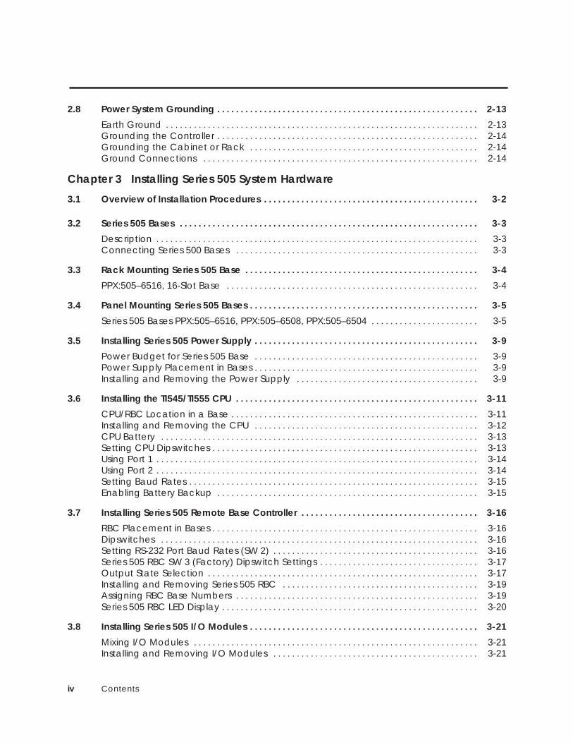
2.8 Power System Grounding 2-13. . . . . . . . . . . . . . . . . . . . . . . . . . . . . . . . . . . . . . . . . . . . . . . . . . . . . . . .
Earth Ground 2-13. . . . . . . . . . . . . . . . . . . . . . . . . . . . . . . . . . . . . . . . . . . . . . . . . . . . . . . . . . . . . . . . . . . Grounding the Controller 2-14. . . . . . . . . . . . . . . . . . . . . . . . . . . . . . . . . . . . . . . . . . . . . . . . . . . . . . . . Grounding the Cabinet or Rack 2-14. . . . . . . . . . . . . . . . . . . . . . . . . . . . . . . . . . . . . . . . . . . . . . . . . Ground Connections 2-14. . . . . . . . . . . . . . . . . . . . . . . . . . . . . . . . . . . . . . . . . . . . . . . . . . . . . . . . . . .
Chapter 3 Installing Series 505 System Hardware
3.1 Overview of Installation Procedures 3-2. . . . . . . . . . . . . . . . . . . . . . . . . . . . . . . . . . . . . . . . . . . . . .
3.2 Series 505 Bases 3-3. . . . . . . . . . . . . . . . . . . . . . . . . . . . . . . . . . . . . . . . . . . . . . . . . . . . . . . . . . . . . . . .
Description 3-3. . . . . . . . . . . . . . . . . . . . . . . . . . . . . . . . . . . . . . . . . . . . . . . . . . . . . . . . . . . . . . . . . . . . . Connecting Series 500 Bases 3-3. . . . . . . . . . . . . . . . . . . . . . . . . . . . . . . . . . . . . . . . . . . . . . . . . . . .
3.3 Rack Mounting Series 505 Base 3-4. . . . . . . . . . . . . . . . . . . . . . . . . . . . . . . . . . . . . . . . . . . . . . . . . .
PPX:505–6516, 16-Slot Base 3-4. . . . . . . . . . . . . . . . . . . . . . . . . . . . . . . . . . . . . . . . . . . . . . . . . . . . . .
3.4 Panel Mounting Series 505 Bases 3-5. . . . . . . . . . . . . . . . . . . . . . . . . . . . . . . . . . . . . . . . . . . . . . . . .
Series 505 Bases PPX:505–6516, PPX:505–6508, PPX:505–6504 3-5. . . . . . . . . . . . . . . . . . . . . . .
3.5 Installing Series 505 Power Supply 3-9. . . . . . . . . . . . . . . . . . . . . . . . . . . . . . . . . . . . . . . . . . . . . . . .
Power Budget for Series 505 Base 3-9. . . . . . . . . . . . . . . . . . . . . . . . . . . . . . . . . . . . . . . . . . . . . . . . Power Supply Placement in Bases 3-9. . . . . . . . . . . . . . . . . . . . . . . . . . . . . . . . . . . . . . . . . . . . . . . . Installing and Removing the Power Supply 3-9. . . . . . . . . . . . . . . . . . . . . . . . . . . . . . . . . . . . . . .
3.6 Installing the TI545/TI555 CPU 3-11. . . . . . . . . . . . . . . . . . . . . . . . . . . . . . . . . . . . . . . . . . . . . . . . . . . .
CPU/RBC Location in a Base 3-11. . . . . . . . . . . . . . . . . . . . . . . . . . . . . . . . . . . . . . . . . . . . . . . . . . . . . Installing and Removing the CPU 3-12. . . . . . . . . . . . . . . . . . . . . . . . . . . . . . . . . . . . . . . . . . . . . . . . CPU Battery 3-13. . . . . . . . . . . . . . . . . . . . . . . . . . . . . . . . . . . . . . . . . . . . . . . . . . . . . . . . . . . . . . . . . . . . Setting CPU Dipswitches 3-13. . . . . . . . . . . . . . . . . . . . . . . . . . . . . . . . . . . . . . . . . . . . . . . . . . . . . . . . . Using Port 1 3-14. . . . . . . . . . . . . . . . . . . . . . . . . . . . . . . . . . . . . . . . . . . . . . . . . . . . . . . . . . . . . . . . . . . . . Using Port 2 3-14. . . . . . . . . . . . . . . . . . . . . . . . . . . . . . . . . . . . . . . . . . . . . . . . . . . . . . . . . . . . . . . . . . . . . Setting Baud Rates 3-15. . . . . . . . . . . . . . . . . . . . . . . . . . . . . . . . . . . . . . . . . . . . . . . . . . . . . . . . . . . . . . Enabling Battery Backup 3-15. . . . . . . . . . . . . . . . . . . . . . . . . . . . . . . . . . . . . . . . . . . . . . . . . . . . . . . .
3.7 Installing Series 505 Remote Base Controller 3-16. . . . . . . . . . . . . . . . . . . . . . . . . . . . . . . . . . . . . .
RBC Placement in Bases 3-16. . . . . . . . . . . . . . . . . . . . . . . . . . . . . . . . . . . . . . . . . . . . . . . . . . . . . . . . . Dipswitches 3-16. . . . . . . . . . . . . . . . . . . . . . . . . . . . . . . . . . . . . . . . . . . . . . . . . . . . . . . . . . . . . . . . . . . . Setting RS-232 Port Baud Rates (SW 2) 3-16. . . . . . . . . . . . . . . . . . . . . . . . . . . . . . . . . . . . . . . . . . . . Series 505 RBC SW 3 (Factory) Dipswitch Settings 3-17. . . . . . . . . . . . . . . . . . . . . . . . . . . . . . . . . . Output State Selection 3-17. . . . . . . . . . . . . . . . . . . . . . . . . . . . . . . . . . . . . . . . . . . . . . . . . . . . . . . . . . Installing and Removing Series 505 RBC 3-19. . . . . . . . . . . . . . . . . . . . . . . . . . . . . . . . . . . . . . . . . . Assigning RBC Base Numbers 3-19. . . . . . . . . . . . . . . . . . . . . . . . . . . . . . . . . . . . . . . . . . . . . . . . . . . . Series 505 RBC LED Display 3-20. . . . . . . . . . . . . . . . . . . . . . . . . . . . . . . . . . . . . . . . . . . . . . . . . . . . . . .
3.8 Installing Series 505 I/O Modules 3-21. . . . . . . . . . . . . . . . . . . . . . . . . . . . . . . . . . . . . . . . . . . . . . . . .
Mixing I/O Modules 3-21. . . . . . . . . . . . . . . . . . . . . . . . . . . . . . . . . . . . . . . . . . . . . . . . . . . . . . . . . . . . . Installing and Removing I/O Modules 3-21. . . . . . . . . . . . . . . . . . . . . . . . . . . . . . . . . . . . . . . . . . . .
Contents v
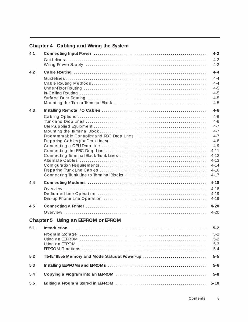
Chapter 4 Cabling and Wiring the System4.1 Connecting Input Power 4-2. . . . . . . . . . . . . . . . . . . . . . . . . . . . . . . . . . . . . . . . . . . . . . . . . . . . . . . .
Guidelines 4-2. . . . . . . . . . . . . . . . . . . . . . . . . . . . . . . . . . . . . . . . . . . . . . . . . . . . . . . . . . . . . . . . . . . . . . Wiring Power Supply 4-2. . . . . . . . . . . . . . . . . . . . . . . . . . . . . . . . . . . . . . . . . . . . . . . . . . . . . . . . . . . .
4.2 Cable Routing 4-4. . . . . . . . . . . . . . . . . . . . . . . . . . . . . . . . . . . . . . . . . . . . . . . . . . . . . . . . . . . . . . . . . . Guidelines 4-4. . . . . . . . . . . . . . . . . . . . . . . . . . . . . . . . . . . . . . . . . . . . . . . . . . . . . . . . . . . . . . . . . . . . . . Cable Routing Methods 4-4. . . . . . . . . . . . . . . . . . . . . . . . . . . . . . . . . . . . . . . . . . . . . . . . . . . . . . . . . Under-Floor Routing 4-5. . . . . . . . . . . . . . . . . . . . . . . . . . . . . . . . . . . . . . . . . . . . . . . . . . . . . . . . . . . . . In-Ceiling Routing 4-5. . . . . . . . . . . . . . . . . . . . . . . . . . . . . . . . . . . . . . . . . . . . . . . . . . . . . . . . . . . . . . . Surface Duct Routing 4-5. . . . . . . . . . . . . . . . . . . . . . . . . . . . . . . . . . . . . . . . . . . . . . . . . . . . . . . . . . . Mounting the Tap or Terminal Block 4-5. . . . . . . . . . . . . . . . . . . . . . . . . . . . . . . . . . . . . . . . . . . . . .
4.3 Installing Remote I/O Cables 4-6. . . . . . . . . . . . . . . . . . . . . . . . . . . . . . . . . . . . . . . . . . . . . . . . . . . . Cabling Options 4-6. . . . . . . . . . . . . . . . . . . . . . . . . . . . . . . . . . . . . . . . . . . . . . . . . . . . . . . . . . . . . . . . Trunk and Drop Lines 4-6. . . . . . . . . . . . . . . . . . . . . . . . . . . . . . . . . . . . . . . . . . . . . . . . . . . . . . . . . . . . User-Supplied Equipment 4-7. . . . . . . . . . . . . . . . . . . . . . . . . . . . . . . . . . . . . . . . . . . . . . . . . . . . . . . . Mounting the Terminal Block 4-7. . . . . . . . . . . . . . . . . . . . . . . . . . . . . . . . . . . . . . . . . . . . . . . . . . . . . Programmable Controller and RBC Drop Lines 4-7. . . . . . . . . . . . . . . . . . . . . . . . . . . . . . . . . . . . Preparing Cables (for Drop Lines) 4-8. . . . . . . . . . . . . . . . . . . . . . . . . . . . . . . . . . . . . . . . . . . . . . . . Connecting a CPU Drop Line 4-9. . . . . . . . . . . . . . . . . . . . . . . . . . . . . . . . . . . . . . . . . . . . . . . . . . . . Connecting the RBC Drop Line 4-11. . . . . . . . . . . . . . . . . . . . . . . . . . . . . . . . . . . . . . . . . . . . . . . . . . Connecting Terminal Block Trunk Lines 4-12. . . . . . . . . . . . . . . . . . . . . . . . . . . . . . . . . . . . . . . . . . . Alternate Cables 4-13. . . . . . . . . . . . . . . . . . . . . . . . . . . . . . . . . . . . . . . . . . . . . . . . . . . . . . . . . . . . . . . Configuration Requirements 4-14. . . . . . . . . . . . . . . . . . . . . . . . . . . . . . . . . . . . . . . . . . . . . . . . . . . . . Preparing Trunk Line Cables 4-16. . . . . . . . . . . . . . . . . . . . . . . . . . . . . . . . . . . . . . . . . . . . . . . . . . . . . Connecting Trunk Line to Terminal Blocks 4-17. . . . . . . . . . . . . . . . . . . . . . . . . . . . . . . . . . . . . . . . .
4.4 Connecting Modems 4-18. . . . . . . . . . . . . . . . . . . . . . . . . . . . . . . . . . . . . . . . . . . . . . . . . . . . . . . . . . . Overview 4-18. . . . . . . . . . . . . . . . . . . . . . . . . . . . . . . . . . . . . . . . . . . . . . . . . . . . . . . . . . . . . . . . . . . . . . . Dedicated Line Operation 4-19. . . . . . . . . . . . . . . . . . . . . . . . . . . . . . . . . . . . . . . . . . . . . . . . . . . . . . Dial-up Phone Line Operation 4-19. . . . . . . . . . . . . . . . . . . . . . . . . . . . . . . . . . . . . . . . . . . . . . . . . . .
4.5 Connecting a Printer 4-20. . . . . . . . . . . . . . . . . . . . . . . . . . . . . . . . . . . . . . . . . . . . . . . . . . . . . . . . . . . . Overview 4-20. . . . . . . . . . . . . . . . . . . . . . . . . . . . . . . . . . . . . . . . . . . . . . . . . . . . . . . . . . . . . . . . . . . . . . .
Chapter 5 Using an EEPROM or EPROM5.1 Introduction 5-2. . . . . . . . . . . . . . . . . . . . . . . . . . . . . . . . . . . . . . . . . . . . . . . . . . . . . . . . . . . . . . . . . . . .
Program Storage 5-2. . . . . . . . . . . . . . . . . . . . . . . . . . . . . . . . . . . . . . . . . . . . . . . . . . . . . . . . . . . . . . . Using an EEPROM 5-2. . . . . . . . . . . . . . . . . . . . . . . . . . . . . . . . . . . . . . . . . . . . . . . . . . . . . . . . . . . . . . . Using an EPROM 5-3. . . . . . . . . . . . . . . . . . . . . . . . . . . . . . . . . . . . . . . . . . . . . . . . . . . . . . . . . . . . . . . . EEPROM Functions 5-4. . . . . . . . . . . . . . . . . . . . . . . . . . . . . . . . . . . . . . . . . . . . . . . . . . . . . . . . . . . . . .
5.2 TI545/TI555 Memory and Mode Status at Power-up 5-5. . . . . . . . . . . . . . . . . . . . . . . . . . . . . . . .
5.3 Installing EEPROMs and EPROMs 5-6. . . . . . . . . . . . . . . . . . . . . . . . . . . . . . . . . . . . . . . . . . . . . . . . .
5.4 Copying a Program into an EEPROM 5-8. . . . . . . . . . . . . . . . . . . . . . . . . . . . . . . . . . . . . . . . . . . . .
5.5 Editing a Program Stored in EEPROM 5-10. . . . . . . . . . . . . . . . . . . . . . . . . . . . . . . . . . . . . . . . . . . . .
vi Contents
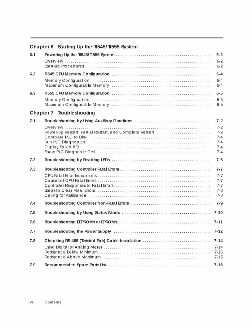
Chapter 6 Starting Up the TI545/TI555 System6.1 Powering Up the TI545/TI555 System 6-2. . . . . . . . . . . . . . . . . . . . . . . . . . . . . . . . . . . . . . . . . . . . . .
Overview 6-2. . . . . . . . . . . . . . . . . . . . . . . . . . . . . . . . . . . . . . . . . . . . . . . . . . . . . . . . . . . . . . . . . . . . . . . Start-up Procedures 6-2. . . . . . . . . . . . . . . . . . . . . . . . . . . . . . . . . . . . . . . . . . . . . . . . . . . . . . . . . . . . .
6.2 TI545 CPU Memory Configuration 6-4. . . . . . . . . . . . . . . . . . . . . . . . . . . . . . . . . . . . . . . . . . . . . . . . Memory Configuration 6-4. . . . . . . . . . . . . . . . . . . . . . . . . . . . . . . . . . . . . . . . . . . . . . . . . . . . . . . . . . Maximum Configurable Memory 6-4. . . . . . . . . . . . . . . . . . . . . . . . . . . . . . . . . . . . . . . . . . . . . . . .
6.3 TI555 CPU Memory Configuration 6-5. . . . . . . . . . . . . . . . . . . . . . . . . . . . . . . . . . . . . . . . . . . . . . . . Memory Configuration 6-5. . . . . . . . . . . . . . . . . . . . . . . . . . . . . . . . . . . . . . . . . . . . . . . . . . . . . . . . . . Maximum Configurable Memory 6-5. . . . . . . . . . . . . . . . . . . . . . . . . . . . . . . . . . . . . . . . . . . . . . . .
Chapter 7 Troubleshooting7.1 Troubleshooting by Using Auxiliary Functions 7-2. . . . . . . . . . . . . . . . . . . . . . . . . . . . . . . . . . . . .
Overview 7-2. . . . . . . . . . . . . . . . . . . . . . . . . . . . . . . . . . . . . . . . . . . . . . . . . . . . . . . . . . . . . . . . . . . . . . . Power-up Restart, Partial Restart, and Complete Restart 7-2. . . . . . . . . . . . . . . . . . . . . . . . . . Compare PLC to Disk 7-4. . . . . . . . . . . . . . . . . . . . . . . . . . . . . . . . . . . . . . . . . . . . . . . . . . . . . . . . . . . Run PLC Diagnostics 7-4. . . . . . . . . . . . . . . . . . . . . . . . . . . . . . . . . . . . . . . . . . . . . . . . . . . . . . . . . . . . Display Failed I/O 7-4. . . . . . . . . . . . . . . . . . . . . . . . . . . . . . . . . . . . . . . . . . . . . . . . . . . . . . . . . . . . . . . Show PLC Diagnostic Cell 7-4. . . . . . . . . . . . . . . . . . . . . . . . . . . . . . . . . . . . . . . . . . . . . . . . . . . . . . .
7.2 Troubleshooting by Reading LEDs 7-6. . . . . . . . . . . . . . . . . . . . . . . . . . . . . . . . . . . . . . . . . . . . . . . .
7.3 Troubleshooting Controller Fatal Errors 7-7. . . . . . . . . . . . . . . . . . . . . . . . . . . . . . . . . . . . . . . . . . . . CPU Fatal Error Indications 7-7. . . . . . . . . . . . . . . . . . . . . . . . . . . . . . . . . . . . . . . . . . . . . . . . . . . . . . . Causes of CPU Fatal Errors 7-7. . . . . . . . . . . . . . . . . . . . . . . . . . . . . . . . . . . . . . . . . . . . . . . . . . . . . . . Controller Responses to Fatal Errors 7-7. . . . . . . . . . . . . . . . . . . . . . . . . . . . . . . . . . . . . . . . . . . . . . Steps to Clear Fatal Errors 7-8. . . . . . . . . . . . . . . . . . . . . . . . . . . . . . . . . . . . . . . . . . . . . . . . . . . . . . . Calling for Assistance 7-8. . . . . . . . . . . . . . . . . . . . . . . . . . . . . . . . . . . . . . . . . . . . . . . . . . . . . . . . . . .
7.4 Troubleshooting Controller Non-Fatal Errors 7-9. . . . . . . . . . . . . . . . . . . . . . . . . . . . . . . . . . . . . . .
7.5 Troubleshooting by Using Status Words 7-10. . . . . . . . . . . . . . . . . . . . . . . . . . . . . . . . . . . . . . . . . . .
7.6 Troubleshooting EEPROMs or EPROMs 7-11. . . . . . . . . . . . . . . . . . . . . . . . . . . . . . . . . . . . . . . . . . . . .
7.7 Troubleshooting the Power Supply 7-12. . . . . . . . . . . . . . . . . . . . . . . . . . . . . . . . . . . . . . . . . . . . . . .
7.8 Checking RS-485 (Twisted Pair) Cable Installation 7-14. . . . . . . . . . . . . . . . . . . . . . . . . . . . . . . . . Using Digital or Analog Meter 7-14. . . . . . . . . . . . . . . . . . . . . . . . . . . . . . . . . . . . . . . . . . . . . . . . . . . . Resistance Below Minimum 7-15. . . . . . . . . . . . . . . . . . . . . . . . . . . . . . . . . . . . . . . . . . . . . . . . . . . . . . Resistance Above Maximum 7-15. . . . . . . . . . . . . . . . . . . . . . . . . . . . . . . . . . . . . . . . . . . . . . . . . . . .
7.9 Recommended Spare Parts List 7-16. . . . . . . . . . . . . . . . . . . . . . . . . . . . . . . . . . . . . . . . . . . . . . . . . .

Contents vii
Appendix A System SpecificationsA.1 Series 505 System Specifications A-2. . . . . . . . . . . . . . . . . . . . . . . . . . . . . . . . . . . . . . . . . . . . . . . . .
Appendix B Module Power ConsumptionB.1 Series 505 Modules B-2. . . . . . . . . . . . . . . . . . . . . . . . . . . . . . . . . . . . . . . . . . . . . . . . . . . . . . . . . . . . .
Appendix C TI545/TI555 CPU and I/O CompatibilityC.1 I/O Module Compatibility C-2. . . . . . . . . . . . . . . . . . . . . . . . . . . . . . . . . . . . . . . . . . . . . . . . . . . . . . .
I/O Modules not Compatible with TI545/TI555 CPUs C-2. . . . . . . . . . . . . . . . . . . . . . . . . . . . . . . Determining the Compatibility of a Module C-3. . . . . . . . . . . . . . . . . . . . . . . . . . . . . . . . . . . . . . Series 505 High Speed Counter C-3. . . . . . . . . . . . . . . . . . . . . . . . . . . . . . . . . . . . . . . . . . . . . . . . . .
C.2 Reading the Serial Numbers C-4. . . . . . . . . . . . . . . . . . . . . . . . . . . . . . . . . . . . . . . . . . . . . . . . . . . . . Determining the Manufacturing Date C-4. . . . . . . . . . . . . . . . . . . . . . . . . . . . . . . . . . . . . . . . . . . . Examples C-4. . . . . . . . . . . . . . . . . . . . . . . . . . . . . . . . . . . . . . . . . . . . . . . . . . . . . . . . . . . . . . . . . . . . . . . 86ML8712020175_ C-4. . . . . . . . . . . . . . . . . . . . . . . . . . . . . . . . . . . . . . . . . . . . . . . . . . . . . . . . . . . . . . . 86ML8712020175G C-4. . . . . . . . . . . . . . . . . . . . . . . . . . . . . . . . . . . . . . . . . . . . . . . . . . . . . . . . . . . . . . 86ML8801041324_ C-4. . . . . . . . . . . . . . . . . . . . . . . . . . . . . . . . . . . . . . . . . . . . . . . . . . . . . . . . . . . . . . .
Appendix D Upgrading Series 500 InstallationsD.1 Series 500 System Installations D-2. . . . . . . . . . . . . . . . . . . . . . . . . . . . . . . . . . . . . . . . . . . . . . . . . . .
D.2 Upgrading a TI520/TI520C/TI530/TI530C/TI530T System D-3. . . . . . . . . . . . . . . . . . . . . . . . . . . . Install RS-485 Twin Axial Cabling D-3. . . . . . . . . . . . . . . . . . . . . . . . . . . . . . . . . . . . . . . . . . . . . . . . . . Check Base to be Upgraded D-4. . . . . . . . . . . . . . . . . . . . . . . . . . . . . . . . . . . . . . . . . . . . . . . . . . . . Upgrading 14-Slot, 12-Slot, 6-Slot Bases D-4. . . . . . . . . . . . . . . . . . . . . . . . . . . . . . . . . . . . . . . . . . . Upgrading 16-Slot and 8-Slot Bases D-4. . . . . . . . . . . . . . . . . . . . . . . . . . . . . . . . . . . . . . . . . . . . . . Finish Upgrade with these Steps D-4. . . . . . . . . . . . . . . . . . . . . . . . . . . . . . . . . . . . . . . . . . . . . . . . . .
D.3 Upgrading an RS-485 Based TI560/TI565/TI560T/TI565P System D-6. . . . . . . . . . . . . . . . . . . . .
D.4 Upgrading an RF Based TI560/TI565/TI560T/TI565P System D-8. . . . . . . . . . . . . . . . . . . . . . . . . .
D.5 Installing a PPX:500-5114A RBC D-10. . . . . . . . . . . . . . . . . . . . . . . . . . . . . . . . . . . . . . . . . . . . . . . . . . Output State Selection D-10. . . . . . . . . . . . . . . . . . . . . . . . . . . . . . . . . . . . . . . . . . . . . . . . . . . . . . . . . . Installing a Series 500 RBC D-11. . . . . . . . . . . . . . . . . . . . . . . . . . . . . . . . . . . . . . . . . . . . . . . . . . . . . . . Setting Baud Rates D-12. . . . . . . . . . . . . . . . . . . . . . . . . . . . . . . . . . . . . . . . . . . . . . . . . . . . . . . . . . . . . . Assigning Base Numbers D-12. . . . . . . . . . . . . . . . . . . . . . . . . . . . . . . . . . . . . . . . . . . . . . . . . . . . . . . . . Series 500 RBC LED Display D-13. . . . . . . . . . . . . . . . . . . . . . . . . . . . . . . . . . . . . . . . . . . . . . . . . . . . . . .

viii Contents
List of Figures
Figure 1-1 Typical TI555-1102 Control System 1-4. . . . . . . . . . . . . . . . . . . . . . . . . . . . . . . . . . . . . . . . . . . . Figure 1-2 TI545/TI555 System Using Series 500 and Series 505 Components 1-5. . . . . . . . . . . . . . .
Figure 2-1 Operator Safety Switch 2-4. . . . . . . . . . . . . . . . . . . . . . . . . . . . . . . . . . . . . . . . . . . . . . . . . . . . . Figure 2-2 Emergency Stop Switch 2-4. . . . . . . . . . . . . . . . . . . . . . . . . . . . . . . . . . . . . . . . . . . . . . . . . . . . . Figure 2-3 JOG or INCH Switch 2-5. . . . . . . . . . . . . . . . . . . . . . . . . . . . . . . . . . . . . . . . . . . . . . . . . . . . . . . . . Figure 2-4 Fuse/Circuit Breaker Placement 2-7. . . . . . . . . . . . . . . . . . . . . . . . . . . . . . . . . . . . . . . . . . . . . Figure 2-5 Load Noise Snubbing 2-9. . . . . . . . . . . . . . . . . . . . . . . . . . . . . . . . . . . . . . . . . . . . . . . . . . . . . . . Figure 2-6 Contact Noise Snubbing 2-10. . . . . . . . . . . . . . . . . . . . . . . . . . . . . . . . . . . . . . . . . . . . . . . . . . . . Figure 2-7 Grounding Shielded, Twisted Pair Cables 2-11. . . . . . . . . . . . . . . . . . . . . . . . . . . . . . . . . . . . . Figure 2-8 Isolating Ground and Neutral From Conduit 2-13. . . . . . . . . . . . . . . . . . . . . . . . . . . . . . . . . . Figure 2-9 Grounding the TI545/TI555 Controller 2-14. . . . . . . . . . . . . . . . . . . . . . . . . . . . . . . . . . . . . . . . . Figure 2-10 Example of Ground Connection 2-15. . . . . . . . . . . . . . . . . . . . . . . . . . . . . . . . . . . . . . . . . . . .
Figure 3-1 Mounting Base to Standard 19-inch Rack 3-4. . . . . . . . . . . . . . . . . . . . . . . . . . . . . . . . . . . . Figure 3-2 Screw-hole Dimensions for PPX:505–6516/6511 Bases 3-5. . . . . . . . . . . . . . . . . . . . . . . . . . Figure 3-3 Screw-hole Dimensions for PPX:505–6504 Bases 3-6. . . . . . . . . . . . . . . . . . . . . . . . . . . . . . . Figure 3-4 Screw-hole Dimensions for PPX:505-6508 Bases 3-7. . . . . . . . . . . . . . . . . . . . . . . . . . . . . . . . Figure 3-5 Mounting Brackets to Base 3-8. . . . . . . . . . . . . . . . . . . . . . . . . . . . . . . . . . . . . . . . . . . . . . . . . . Figure 3-6 Mounting Base in NEMA Enclosure 3-8. . . . . . . . . . . . . . . . . . . . . . . . . . . . . . . . . . . . . . . . . . . Figure 3-7 Series 505 Module Placement in Base 3-9. . . . . . . . . . . . . . . . . . . . . . . . . . . . . . . . . . . . . . . . Figure 3-8 Selecting Input Voltage—PPX:505–6660 Only 3-10. . . . . . . . . . . . . . . . . . . . . . . . . . . . . . . . . Figure 3-9 Location of CPU/RBC in a Series 505 Base 3-11. . . . . . . . . . . . . . . . . . . . . . . . . . . . . . . . . . . . Figure 3-10 Installing CPU Module in a Series 505 Base 3-12. . . . . . . . . . . . . . . . . . . . . . . . . . . . . . . . . . . Figure 3-11 CPU Dipswitch Location 3-13. . . . . . . . . . . . . . . . . . . . . . . . . . . . . . . . . . . . . . . . . . . . . . . . . . . . Figure 3-12 TI545/TI555 CPU Port Locations 3-14. . . . . . . . . . . . . . . . . . . . . . . . . . . . . . . . . . . . . . . . . . . . . . Figure 3-13 RBC Dipswitch Location 3-16. . . . . . . . . . . . . . . . . . . . . . . . . . . . . . . . . . . . . . . . . . . . . . . . . . . . Figure 3-14 Series 505 RBC Jumper Locations 3-18. . . . . . . . . . . . . . . . . . . . . . . . . . . . . . . . . . . . . . . . . . . Figure 3-15 Series 505 Remote Base Controller 3-20. . . . . . . . . . . . . . . . . . . . . . . . . . . . . . . . . . . . . . . . . . Figure 3-16 Installing and Removing Modules in a Series 505 Base 3-21. . . . . . . . . . . . . . . . . . . . . . . .
Figure 4-1 Supplying Power with the PPX:505–6660A 4-3. . . . . . . . . . . . . . . . . . . . . . . . . . . . . . . . . . . . . Figure 4-2 Trunk and Drop Line Example 4-6. . . . . . . . . . . . . . . . . . . . . . . . . . . . . . . . . . . . . . . . . . . . . . . . Figure 4-3 9-Pin I/O Female D-Connector Pinout 4-8. . . . . . . . . . . . . . . . . . . . . . . . . . . . . . . . . . . . . . . . Figure 4-4 Connecting to Terminal Block 4-9. . . . . . . . . . . . . . . . . . . . . . . . . . . . . . . . . . . . . . . . . . . . . . . Figure 4-5 Adding a Terminating Resistor 4-10. . . . . . . . . . . . . . . . . . . . . . . . . . . . . . . . . . . . . . . . . . . . . . . Figure 4-6 Attaching RBC to Terminal Block 4-11. . . . . . . . . . . . . . . . . . . . . . . . . . . . . . . . . . . . . . . . . . . . . Figure 4-7 Maximum Trunk Length 4-14. . . . . . . . . . . . . . . . . . . . . . . . . . . . . . . . . . . . . . . . . . . . . . . . . . . . . . Figure 4-8 T Configuration 4-14. . . . . . . . . . . . . . . . . . . . . . . . . . . . . . . . . . . . . . . . . . . . . . . . . . . . . . . . . . . . . Figure 4-9 Multiple Tap Connections in Close Proximity 4-15. . . . . . . . . . . . . . . . . . . . . . . . . . . . . . . . . . Figure 4-10 Spacing between Taps 4-15. . . . . . . . . . . . . . . . . . . . . . . . . . . . . . . . . . . . . . . . . . . . . . . . . . . . Figure 4-11 Connecting Terminal Blocks 4-17. . . . . . . . . . . . . . . . . . . . . . . . . . . . . . . . . . . . . . . . . . . . . . . . Figure 4-12 Modem Configuration 4-18. . . . . . . . . . . . . . . . . . . . . . . . . . . . . . . . . . . . . . . . . . . . . . . . . . . . .

Contents ix
Figure 4-13 XON/XOFF Printer Handshaking 4-20. . . . . . . . . . . . . . . . . . . . . . . . . . . . . . . . . . . . . . . . . . . . . Figure 4-14 READY/BUSY Printer Handshaking 4-20. . . . . . . . . . . . . . . . . . . . . . . . . . . . . . . . . . . . . . . . . . .
Figure 5-1 EEPROM (EPROM) Socket and Jumper Pins 5-7. . . . . . . . . . . . . . . . . . . . . . . . . . . . . . . . . . .
Figure 7-1 Typical AUX Function 29 Screen 7-5. . . . . . . . . . . . . . . . . . . . . . . . . . . . . . . . . . . . . . . . . . . . . . Figure 7-2 Replacing PPX:505–6660 Power Supply Fuse 7-13. . . . . . . . . . . . . . . . . . . . . . . . . . . . . . . . . .
Figure C-1 Serial Number Definition C-4. . . . . . . . . . . . . . . . . . . . . . . . . . . . . . . . . . . . . . . . . . . . . . . . . . . .
Figure D-1 Upgrading a TI520/TI520C/TI530/TI530C/TI530T System D-5. . . . . . . . . . . . . . . . . . . . . . . . Figure D-2 Upgrading an RS-485 Based TI560/TI565/TI560T/TI565P System D-7. . . . . . . . . . . . . . . . . . Figure D-3 Upgrading an RF Based TI560/TI565/TI560T/TI565P System D-9. . . . . . . . . . . . . . . . . . . . . . Figure D-4 Series 500 RBC Switch Selection D-10. . . . . . . . . . . . . . . . . . . . . . . . . . . . . . . . . . . . . . . . . . . . . Figure D-5 Installed Series 500 RBC D-11. . . . . . . . . . . . . . . . . . . . . . . . . . . . . . . . . . . . . . . . . . . . . . . . . . . . . Figure D-6 Series 500 Remote Base Controller and Baud Rate Settings D-12. . . . . . . . . . . . . . . . . . . .
x Contents
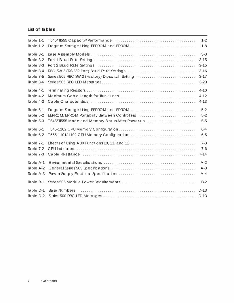
List of Tables
Table 1-1 TI545/TI555 Capacity/Performance 1-2. . . . . . . . . . . . . . . . . . . . . . . . . . . . . . . . . . . . . . . . . . . Table 1-2 Program Storage Using EEPROM and EPROM 1-8. . . . . . . . . . . . . . . . . . . . . . . . . . . . . . . . . .
Table 3-1 Base Assembly Models 3-3. . . . . . . . . . . . . . . . . . . . . . . . . . . . . . . . . . . . . . . . . . . . . . . . . . . . . . . Table 3-2 Port 1 Baud Rate Settings 3-15. . . . . . . . . . . . . . . . . . . . . . . . . . . . . . . . . . . . . . . . . . . . . . . . . . . . Table 3-3 Port 2 Baud Rate Settings 3-15. . . . . . . . . . . . . . . . . . . . . . . . . . . . . . . . . . . . . . . . . . . . . . . . . . . . Table 3-4 RBC SW 2 (RS-232 Port) Baud Rate Settings 3-16. . . . . . . . . . . . . . . . . . . . . . . . . . . . . . . . . . . . Table 3-5 Series 505 RBC SW 3 (Factory) Dipswitch Setting 3-17. . . . . . . . . . . . . . . . . . . . . . . . . . . . . . . Table 3-6 Series 505 RBC LED Messages 3-20. . . . . . . . . . . . . . . . . . . . . . . . . . . . . . . . . . . . . . . . . . . . . . . . .
Table 4-1 Terminating Resistors 4-10. . . . . . . . . . . . . . . . . . . . . . . . . . . . . . . . . . . . . . . . . . . . . . . . . . . . . . . . . Table 4-2 Maximum Cable Length for Trunk Lines 4-12. . . . . . . . . . . . . . . . . . . . . . . . . . . . . . . . . . . . . . . Table 4-3 Cable Characteristics 4-13. . . . . . . . . . . . . . . . . . . . . . . . . . . . . . . . . . . . . . . . . . . . . . . . . . . . . . .
Table 5-1 Program Storage Using EEPROM and EPROM 5-2. . . . . . . . . . . . . . . . . . . . . . . . . . . . . . . . . . Table 5-2 EEPROM/EPROM Portability Between Controllers 5-2. . . . . . . . . . . . . . . . . . . . . . . . . . . . . . Table 5-3 TI545/TI555 Mode and Memory Status After Power-up 5-5. . . . . . . . . . . . . . . . . . . . . . . . .
Table 6-1 TI545-1102 CPU Memory Configuration 6-4. . . . . . . . . . . . . . . . . . . . . . . . . . . . . . . . . . . . . . . . Table 6-2 TI555-1101/1102 CPU Memory Configuration 6-5. . . . . . . . . . . . . . . . . . . . . . . . . . . . . . . . . .
Table 7-1 Effects of Using AUX Functions 10, 11, and 12 7-3. . . . . . . . . . . . . . . . . . . . . . . . . . . . . . . . . . Table 7-2 CPU Indicators 7-6. . . . . . . . . . . . . . . . . . . . . . . . . . . . . . . . . . . . . . . . . . . . . . . . . . . . . . . . . . . . . . Table 7-3 Cable Resistance 7-14. . . . . . . . . . . . . . . . . . . . . . . . . . . . . . . . . . . . . . . . . . . . . . . . . . . . . . . . . . .
Table A-1 Environmental Specifications A-2. . . . . . . . . . . . . . . . . . . . . . . . . . . . . . . . . . . . . . . . . . . . . . . . Table A-2 General Series 505 Specifications A-3. . . . . . . . . . . . . . . . . . . . . . . . . . . . . . . . . . . . . . . . . . . . Table A-3 Power Supply Electrical Specifications A-4. . . . . . . . . . . . . . . . . . . . . . . . . . . . . . . . . . . . . . . .
Table B-1 Series 505 Module Power Requirements B-2. . . . . . . . . . . . . . . . . . . . . . . . . . . . . . . . . . . . . . .
Table D-1 Base Numbers D-13. . . . . . . . . . . . . . . . . . . . . . . . . . . . . . . . . . . . . . . . . . . . . . . . . . . . . . . . . . . . Table D-2 Series 500 RBC LED Messages D-13. . . . . . . . . . . . . . . . . . . . . . . . . . . . . . . . . . . . . . . . . . . . . . . .

Preface xiTI545/TI555 System Manual
Preface
This SIMATIC� TI545 /TI555 System Manual includes requirements andspecifications for preparing your control site and installing aSIMATIC TI545/TI555 Programmable Logic Controller (PLC) system.
NOTE: This manual describes the SIMATIC TI545-1102 CPU, and both theSIMATIC TI555-1101 and -1102 CPUs. Information in this manual does notapply to the SIMATIC TI545-1101 CPU. For the information concerning theSIMATIC TI545-1101 CPU refer to SIMATIC TI545 System Manual:PPX:545-8101-x.
The following major topics are covered.
• Site preparation including power and grounding requirements andother safety considerations.
• Hardware installation including Series 505 bases, power supplies,TI545/TI555 CPUs, Remote Base Controllers (RBCs), and I/O modules.
• Upgrade of Series 500 bases for connection to the TI545/TI555.
• System cable and wiring procedures.
• Using EEPROMs or EPROMs.
• System startup, including modem operation.
• System troubleshooting, including use of AUX functions, status words,and other diagnostic aids.
• General maintenance procedures such as changing power supply fuses.
About this Manual

Prefacexii TI545/TI555 System Manual
Additional manuals that have relevant information include the following:
• SIMATIC� TI505 Programming Reference Manual (PPX:505–8104-5).
• SIMATIC� TI505/TI500 TISOFT Release 5.0 User Manual(PPX:TS505–8101-x).
• SIMATIC TI505 Input/Output Modules User Manual(PPX:505–8105-x).
• SIMATIC TI505 Analog I/O Modules User Manual (PPX:505–8120-x).
• SIMATIC TI505 H1 Communication Processor User Manual(PPX:505–8126–2 or later).
• SIMATIC TI505 Redundant I/O Systems Users Manual,(PPX:505-8125-x).
• SIMATIC TI505 Isolated Interrupt Discrete Input Module User Manual(PPX:505-4317–x) provides information on configuring and installingthe Interrupt Input module (PPX:505–8123-x) which is required for theoperation of interrupt I/O.
Refer to material in these manuals as necessary for additional informationabout programming and operating your TI545/TI555 system.
Series 505 products have been developed with consideration of the draftstandard of the International Electrotechnical Commission Committeeproposed standard (IEC-65A/WG6) for programmable controllers (releasedas IEC 1131–2, Programmable Controllers Part 2: Equipment Requirementsand Tests, First Edition, 1992–09). Contact Siemens Industrial Automation,Inc., for information about regulatory agency approvals that have beenobtained on the TI545/555 systems and Series 505 units.
Agency Approvals are the following:
– UL Listed (industrial control equipment)– CSA Certified (process control equipment)– FM (Class I, Div. 2, Group A, B, C, D Hazardous Locations)
For technical assistance, contact your Siemens Industrial Automation, Inc.distributor or sales office. If you need assistance in contacting your salesagent or distributor in the United States, call 1–800–964–4114.
Related Manuals
Agency Standards
TechnicalAssistance

1-1System OverviewTI545/TI555 System Manual
Chapter 1
System Overview
Chapter 1 System Overview1.1 Features 1-2. . . . . . . . . . . . . . . . . . . . . . . . . . . . . . . . . . . . . . . . . . . . . . . . . . . . . . . . . . . . . . . . . . . . . . . .
1.2 Hardware Description 1-6. . . . . . . . . . . . . . . . . . . . . . . . . . . . . . . . . . . . . . . . . . . . . . . . . . . . . . . . . . . Series 505 Base Assemblies 1-6. . . . . . . . . . . . . . . . . . . . . . . . . . . . . . . . . . . . . . . . . . . . . . . . . . . . . . Local and Remote I/O 1-6. . . . . . . . . . . . . . . . . . . . . . . . . . . . . . . . . . . . . . . . . . . . . . . . . . . . . . . . . . Series 505 Power Supply 1-6. . . . . . . . . . . . . . . . . . . . . . . . . . . . . . . . . . . . . . . . . . . . . . . . . . . . . . . . . Communication Ports 1-7. . . . . . . . . . . . . . . . . . . . . . . . . . . . . . . . . . . . . . . . . . . . . . . . . . . . . . . . . . . I/O Port 1-7. . . . . . . . . . . . . . . . . . . . . . . . . . . . . . . . . . . . . . . . . . . . . . . . . . . . . . . . . . . . . . . . . . . . . . . . Battery Backup 1-7. . . . . . . . . . . . . . . . . . . . . . . . . . . . . . . . . . . . . . . . . . . . . . . . . . . . . . . . . . . . . . . . . Real-time Clock 1-8. . . . . . . . . . . . . . . . . . . . . . . . . . . . . . . . . . . . . . . . . . . . . . . . . . . . . . . . . . . . . . . . Programming Software 1-8. . . . . . . . . . . . . . . . . . . . . . . . . . . . . . . . . . . . . . . . . . . . . . . . . . . . . . . . . . Program Storage in EEPROM 1-8. . . . . . . . . . . . . . . . . . . . . . . . . . . . . . . . . . . . . . . . . . . . . . . . . . . . . Program Storage in EPROM 1-8. . . . . . . . . . . . . . . . . . . . . . . . . . . . . . . . . . . . . . . . . . . . . . . . . . . . . .

1-2 System Overview TI545/TI555 System Manual
1.1 Features
The TI545/TI555 CPUs and support equipment comprise acomputer-controlled system that is capable of controlling complexmanufacturing systems. This system performs the same functions as relays,static control, or card logic control systems. It can detect the change in stateof input signals from such devices as pushbuttons, limit switches, andanalog sensors.
Acting on this information and executing a Relay Ladder Logic (RLL)program stored in memory, the TI545/TI555 CPU produces output signals todrive motor starters, solenoids, pilot lights, modulating control valves, etc.These signals are used to regulate the operation of various pieces ofequipment.
The TI545/TI555 systems offer the following features:
• Memory and I/O capacities and scan performance are summarized inTable 1-1.
Table 1-1 TI545/TI555 Capacity/Performance
FeatureTI545–1102
TI555–1101 –1102
User Memory (bytes) 192K 384K 1920K
EEPROM (EPROM) (bytes) 256K
Discrete I/O Points 2048 1
8192 2Word I/O Points 1024 1
8192 2
Control Relays 32,768
Scan Performance (milliseconds/KW, best case) .67 .07
Notes:1 Total I/O count may not exceed 2,048 points.2 Total I/O count may not exceed 8,192 points.
• Optional password protection for user programs.
• Support for Report By Exception (RBE) when used as a control elementin a SIMATIC� PCS System (Release 3.0 or later).
Features

1-3System OverviewTI545/TI555 System Manual
• Interrupt I/O allows for fast reaction to external events.
• Support for Redundant Remote Base Controller.
• Immediate I/O Updates allow your application program to access an I/Opoint multiple times during a controller scan.
• Cyclic RLL allows you to create an additional RLL program that runsindependently of the main RLL program.
• External subroutines allows your program to call externally developedprograms written in high-level languages such as C.
• Proportional-Integral-Derivative (PID) loop functions for process andbatch control.
• Special Function Programs (SFPGMs) and Special FunctionSubroutines (SFSUBs) that use a higher level statement-drivenprogramming language to ease the development of complex programs.
• Up to 256 SF modules can be used in the TI545/TI555 system.
• A communication port baud rate of up to 19,200 baud to provide fastcommunication with your (programming) operator interfaces.
• Ethernet connectivity using H1 protocol and the CP1434TF H1 module(Rel. 2.0 and later).
• Adjustable processor scan time by using the configurable timelinefunction.
• Analog alarm functionality.
• Non-volatile program storage and execution (EEPROM or EPROM).
• Series 505 footprint.

1-4 System Overview TI545/TI555 System Manual
Features (continued)
CPU GOOD
RUN
BATT GOOD
I/O
555–1102
SIMATICTI555
RS232#1
RS232#2
SIMATICTI505
Siemens
Figure 1-1 Typical TI555–1102 Control System
TI545/TI555 systems (see Figure 1-1) are designed for use in applicationsthat require discrete and analog control. Components include the CPU andthe support devices that provide operator communication, I/O control, andpower (see Figure 1-2).
You can communicate with the CPU by using the following devices:
• IBM� PC/AT� (386 or higher) or a 100% compatible computer, using theSIMATIC� APT or TISOFT software.
• Control Vision Unit (CVU100 , CVU1000 , or CVU10000 ).
• SIMATIC PCS.
1-5System OverviewTI545/TI555 System Manual
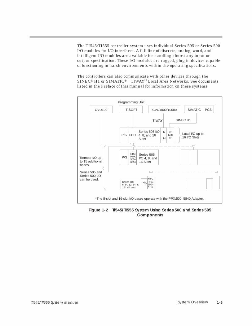
The TI545/TI555 controller system uses individual Series 505 or Series 500I/O modules for I/O interfaces. A full line of discrete, analog, word, andintelligent I/O modules are available for handling almost any input oroutput specification. These I/O modules are rugged, plug-in devices capableof functioning in harsh environments within the operating specifications.
The controllers can also communicate with other devices through theSINEC� H1 or SIMATIC� TIWAY Local Area Networks. See documentslisted in the Preface of this manual for information on these systems.
P/S
P/S
Local I/O up to16 I/O Slots
Remote I/O upto 15 additionalbases.
Series 505 andSeries 500 I/Ocan be used.
P/SRBC
500–5114
*The 8-slot and 16-slot I/O bases operate with the PPX:500–5840 Adapter.
Series 505I/O 4, 8, and16 Slots
TISOFT
Programming Unit
CVU100 CVU1000/10000
Series 5006, 8*, 12, 14, &16* I/O slots
NIM
RBCPPX:505–6851
CPU
PPX:
Series 505 I/O4, 8, and 16Slots
CP
TF1434
TIWAY SINEC H1
SIMATIC PCS
Figure 1-2 TI545/TI555 System Using Series 500 and Series 505Components
1-6 System Overview TI545/TI555 System Manual
1.2 Hardware Description
The CPUs are housed in a Series 505 base assembly. A base assembly hasslots for the CPU or remote base controller (RBC), a power supply, and theI/O modules. Three base assembly models are currently available. Each hasthe following number of slots for I/O modules.
• Model PPX:505–6504, 4 slots.
• Model PPX:505–6508, 8 slots.
• Model PPX:505–6511, 11 slots (redundant). Power supply and media.
• Model PPX:505–6516, 16 slots.
Any base assembly may be used at any point in the system, depending uponthe number of I/O points required.
I/O modules are grouped into local and remote I/O categories dependingupon their physical location. The local I/O comprises those modules locatedin the same base assembly as the CPU. If you install the CPU in baseassembly Model PPX:505–6516, the local I/O may consist of as many as 16I/O modules. The base assembly containing the local I/O is designated 0.
You can connect up to 15 additional base assemblies to the system,numbered 1–15. The I/O modules in these bases make up the remote I/O asshown in Figure 1-2.
Individual I/O modules in the remote bases communicate with the CPUthrough RBCs. The RBC in each remote base transmits information fromthe I/O modules in that base directly to the CPU.
The power supply provides up to 55 W at +5 VDC and 3.75 W at –5 VDC foruse by the CPU and the I/O modules. The PPX:505–6660 power supplyoperates at either 110 VAC or 220 VAC on user-supplied power. A jumper onthe inside of the back of the module is used to select voltage. The modelPPX:505–6663 power supply operates on 24 VDC user-supplied power.
Series 505 BaseAssemblies
Local and RemoteI/O
Series 505Power Supply

1-7System OverviewTI545/TI555 System Manual
The CPU has two communications ports; features and descriptions arelisted below. Both ports are configured as Data Terminal Equipment (DTE).
• Port 1 — RS-232 (9-pin male) is used to either program the CPU by anIBM PC/AT compatible computer with APT or TISOFT, or to attachequipment such as the Timer/Counter Access Module (TCAM), aCVU100, or other operator interface using RS-232. The operatorinterface can be up to 50 feet (15 m) away. A user supplied modem canbe used to extend this distance. Port 1 can also be used to attach aprinter.
• Port 2 — RS-232/RS-423 or RS-422/RS-485 (9-pin male) is used tocommunicate with operator interface equipment. Selection betweenRS-232/423 and RS-422/485 is done with cabling options. Dipswitch 1selects between RS-422 and RS-485 if 422/485 cabling is used. SeeChapter 3, Making Port Selection. Distance constraints are listedbelow.
• RS-232/RS-423 connection for operator interface up to 50 feet.
• RS-422/RS-485 connection to 1000 feet.
The CPU has one Remote I/O port, (9-pin female) used to communicatedirectly with remote base controllers (RBCs). This port uses a twisted,shielded-pair RS-485 cable to communicate with RBCs.
Both Series 505 (see NOTE and Appendix C) and Series 500 I/O modules canbe connected to the TI545/TI555 CPU as remote I/O. The CPU is capable ofdirectly addressing the PPX:505–6851–A RBC in a Series 505 baseassembly, or the PPX:500–5114–A RBC in a Series 500 base assemblyintermixed in the same system. Both RBC models use shielded twisted-paircable. They can be placed up to 3300 feet from the CPU.
NOTE: You cannot use some early model Series 505 I/O modules with aTI545/TI555 CPU. Refer to Appendix C for details.
A permanent, rechargeable battery protects user memory and programmingduring a power outage. Battery memory backup typically lasts six monthsat temperatures ranging from 0° to 60°C.
Battery Damage: If the TI545/TI555 unit is left without power andwith the battery switch on for longer than six months, the batterymay be damaged to the point that it cannot be recharged.
Be aware that the battery will appear to charge, but the memorybackup time will be seriously degraded.
Return a unit in this condition to the factory for batteryreplacement.
CommunicationPorts
I/O Port
Battery Backup
CAUTION!

1-8 System Overview TI545/TI555 System Manual
Hardware Description (continued)
The CPU contains a real-time clock which includes the followinginformation:
• Year (two digits), Month, Day of month, and Day of week.
• Hour, minute, second, tenths and hundredths of a second.
You can use APT to program the CPU. APT is a graphic programmingenvironment that eliminates the need for you to work in relay ladder logicwhen you create your application program. APT presents a familiarstructure for process engineers, allowing them to become more closelyinvolved in up-front design work. When the APT program is compiled, anRLL program code is produced, generating the language with which theelectrician or maintenance person is already familiar. Refer to the APTmanual set for more information.
You can use the TISOFT programming software to create and edit yourapplication program. TISOFT allows you to work directly in the ladder logicenvironment as you design the RLL program. For loops, analog alarms, andSF programs, TISOFT presents menu-driven programming tools.
To program the latest features that are described in the Preface of thismanual, you need TISOFT Release 5.0, which runs on an IBM PC/AT (386or higher) compatible personal computer running MS-DOS� 3.3 or later.
Refer to your TISOFT manual for detailed instructions about how to enter aprogram.
The CPU offers the option of saving your RLL program in a non-volatileform by downloading it to an EEPROM integrated circuit as shown inTable 1-2. A separate programming device is not necessary. Onceprogrammed, an EEPROM can be removed and used in any Release 3.0 orhigher CPU as required. To help ensure equipment compatibility, use onlythe EEPROM model supplied by your distributor.
If your operating program does not change, you can store it permanently onEPROM(s) as shown in Table 1-2. By copying your program from anEEPROM to an EPROM (using an EPROM copier), you can createadditional copies for CPUs that are running the same program.
Table 1-2 Program Storage Using EEPROM and EPROM
Storage Type Size Order Number
EEPROM 128K bytes 2587681–8022
EEPROM 256K bytes 2587681–8030
EPROM 128K bytes 2587681–8023
EPROM 256K bytes 2587681–8031
Real-time Clock
ProgrammingSoftware
Program Storagein EEPROM
Program Storagein EPROM

2-1TI545/TI555 System Manual Pre-installation Guidelines
Chapter 2
Pre-installation Guidelines
Chapter 2 Pre-installation Guidelines2.1 Planning Your Installation 2-2. . . . . . . . . . . . . . . . . . . . . . . . . . . . . . . . . . . . . . . . . . . . . . . . . . . . . . . .
Defining Control 2-2. . . . . . . . . . . . . . . . . . . . . . . . . . . . . . . . . . . . . . . . . . . . . . . . . . . . . . . . . . . . . . . . Calculating Power Needs 2-2. . . . . . . . . . . . . . . . . . . . . . . . . . . . . . . . . . . . . . . . . . . . . . . . . . . . . . .
2.2 Safety Considerations 2-3. . . . . . . . . . . . . . . . . . . . . . . . . . . . . . . . . . . . . . . . . . . . . . . . . . . . . . . . . . . Operator Safety Switches 2-4. . . . . . . . . . . . . . . . . . . . . . . . . . . . . . . . . . . . . . . . . . . . . . . . . . . . . . . Emergency Stop Switch 2-4. . . . . . . . . . . . . . . . . . . . . . . . . . . . . . . . . . . . . . . . . . . . . . . . . . . . . . . . . JOG or INCH Switch 2-5. . . . . . . . . . . . . . . . . . . . . . . . . . . . . . . . . . . . . . . . . . . . . . . . . . . . . . . . . . . . .
2.3 Enclosure and Temperature Considerations 2-6. . . . . . . . . . . . . . . . . . . . . . . . . . . . . . . . . . . . . . Enclosure Selection 2-6. . . . . . . . . . . . . . . . . . . . . . . . . . . . . . . . . . . . . . . . . . . . . . . . . . . . . . . . . . . . . Temperature Considerations 2-6. . . . . . . . . . . . . . . . . . . . . . . . . . . . . . . . . . . . . . . . . . . . . . . . . . . . .
2.4 Guidelines for Fuses/Circuit Breakers 2-7. . . . . . . . . . . . . . . . . . . . . . . . . . . . . . . . . . . . . . . . . . . . . Fusing the Controller and Remote I/O Base 2-7. . . . . . . . . . . . . . . . . . . . . . . . . . . . . . . . . . . . . . .
2.5 Definition and Source of Electrical Noise 2-8. . . . . . . . . . . . . . . . . . . . . . . . . . . . . . . . . . . . . . . . . Electrical Noise 2-8. . . . . . . . . . . . . . . . . . . . . . . . . . . . . . . . . . . . . . . . . . . . . . . . . . . . . . . . . . . . . . . . .
2.6 Correcting Noise Problems 2-9. . . . . . . . . . . . . . . . . . . . . . . . . . . . . . . . . . . . . . . . . . . . . . . . . . . . . . Noise Snubbing 2-9. . . . . . . . . . . . . . . . . . . . . . . . . . . . . . . . . . . . . . . . . . . . . . . . . . . . . . . . . . . . . . . . . Noise Isolation 2-11. . . . . . . . . . . . . . . . . . . . . . . . . . . . . . . . . . . . . . . . . . . . . . . . . . . . . . . . . . . . . . . . . .
2.7 Wiring Considerations 2-12. . . . . . . . . . . . . . . . . . . . . . . . . . . . . . . . . . . . . . . . . . . . . . . . . . . . . . . . . . . Guidelines 2-12. . . . . . . . . . . . . . . . . . . . . . . . . . . . . . . . . . . . . . . . . . . . . . . . . . . . . . . . . . . . . . . . . . . . . .
2.8 Power System Grounding 2-13. . . . . . . . . . . . . . . . . . . . . . . . . . . . . . . . . . . . . . . . . . . . . . . . . . . . . . . . Earth Ground 2-13. . . . . . . . . . . . . . . . . . . . . . . . . . . . . . . . . . . . . . . . . . . . . . . . . . . . . . . . . . . . . . . . . . . Grounding the Controller 2-14. . . . . . . . . . . . . . . . . . . . . . . . . . . . . . . . . . . . . . . . . . . . . . . . . . . . . . . . Grounding the Cabinet or Rack 2-14. . . . . . . . . . . . . . . . . . . . . . . . . . . . . . . . . . . . . . . . . . . . . . . . . Ground Connections 2-14. . . . . . . . . . . . . . . . . . . . . . . . . . . . . . . . . . . . . . . . . . . . . . . . . . . . . . . . . . .

2-2 Pre-installation Guidelines TI545/TI555 System Manual
2.1 Planning Your Installation
Preparing the site for installation of your TI545/TI555 controller consists ofthe following tasks.
• Defining control requirements
• Determining the number of controllers needed
• Determining the panel and grounding layout
NOTE: Since no two applications are identical, use these recommendationsas general guidelines only.
Use the following steps to define your control requirements:
• Define the number and type of inputs and outputs you need.
• Calculate the number of I/O modules and bases that you need.
• Determine the power requirements and mounting space needed.
• Consider availability of space (including growth potential). This isparticularly true if several double-wide modules are needed.
Calculate a power budget for each base prior to installation. The powerrequirements of all modules must be included in the calculations — thecontroller, the base controllers, as well as the I/O modules. Theuser-supplied power to individual modules is not a part of the power budgetcalculation. Refer to Appendix B for Series 505 module power consumptioninformation.
To help ensure reliable system operation, the total power required for thecontroller and I/O modules must not exceed the total power available fromthe system power supply. Refer to Chapter 3 for Series 505 power budget.
Defining Control
Calculating PowerNeeds

2-3TI545/TI555 System Manual Pre-installation Guidelines
2.2 Safety Considerations
Pre-installation planning and site preparation must include consideration ofhazards to personnel in the event of a system failure. The equipmentconnected to the control system must include interlocks and safety switchesto help prevent operation during a system failure. Although the specificsteps depend on the application, the general precautions include thefollowing data.
Control devices can fail in an unsafe condition. This means that,unless you incorporate proper safeguards, certain malfunctions ofthese devices could lead to a sudden equipment startup orshutdown. Such a startup or shutdown could result in propertydamage and/or death or severe physical injury to the equipmentoperator. Failure can also be exhibited as erratic or unexpectedoperation.
If you, or your company, use any programmable controllers withequipment which requires an operator or attendant, you should beaware that this potential safety hazard exists and take appropriateprecautions. Although the specific design steps depend on yourparticular application, the following precautions generally apply toinstallation of solid-state programmable control devices.
These precautions conform to the guidelines for installation ofProgrammable Controllers as recommended in the NEMA ICS 3–304Programmable Control Standards.
ICS 3-304.81 Safety Recommendations:
Consideration should be given to the use of an emergency stop function which isindependent of the programmable controller.
Where the operator is exposed to the machinery, such as in loading or unloading amachine tool, or where the machine cycles automatically, consideration should begiven to the use of an electromechanical override or other redundant means,independent of the programmable controller, for starting and interrupting the cycle.
If provision is required for changing programs while the equipment is in operation,consideration should be given to the use of locks or other means of assuring that suchchanges can be made only by authorized personnel.
These recommendations are intended as safeguards against the failure of criticalcomponents and the effects of such failures or the inadvertent errors that might beintroduced if programs are changed while the equipment is in operation.
The ICS 3-304.81 Safety Recommendations from NEMA ICS 3-304, Programmable Control-ler Standard. Recommendations are reproduced by permission of the National ElectricalManufacturers Association.
WARNING!
2-4 Pre-installation Guidelines TI545/TI555 System Manual
Safety Considerations (continued)
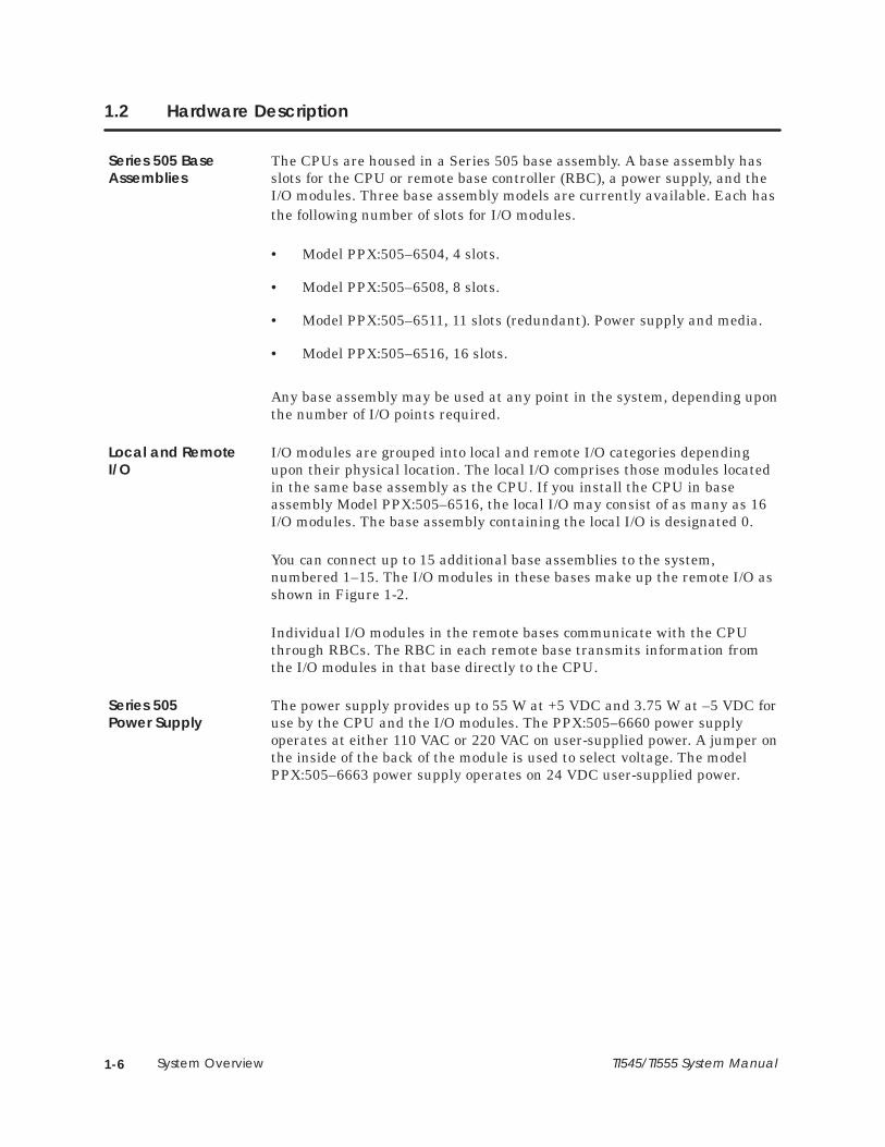
Provide a means for disconnecting power — independent of the controller —from the output loads when a machine is not operating, or when it isnecessary for the operator to reach into the machine. Power must beremoved by a non-semiconductor switch or a physically-wired relay contact,placed to interrupt power to the output. It is not sufficient to rely solely onthe controller for this function. Figure 2-1 shows an operator safety switch.
OutputModule
Relay contacts or limit switchesopen when operator mustreach into machine.
User-suppliedcritical loadswhich couldcause injury
Loads whichcould notcause injury
Output points fromthe programmable control system
Figure 2-1 Operator Safety Switch
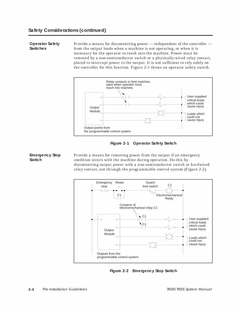
Provide a means for removing power from the output if an emergencycondition occurs with the machine during operation. Do this bydisconnecting output power with a non-semiconductor switch or hardwiredrelay contact, not through the programmable control system (Figure 2-2).
OutputModule
Contacts ofelectromechanical relay C1
User-suppliedcritical loadswhich couldcause injury
Loads whichcould notcause injury
Outputs from theprogrammable control system
C1
C1
Emergencystop
ResetC1
ElectromechanicalRelay
Guardlimit switch
C1
Figure 2-2 Emergency Stop Switch
Operator SafetySwitches
Emergency StopSwitch

2-5TI545/TI555 System Manual Pre-installation Guidelines
Bypass the programmable control system with an external JOG or INCHswitch during machine loading or setup operations. See Figure 2-3.
OutputModule
User-suppliedcritical loadswhich couldcause injury
Outputs from theprogrammable controller
Jog
Switch or contactopen in the JOGor INCH mode
Switch or contactclosed in the jogor inch mode
Figure 2-3 JOG or INCH Switch
JOG or INCHSwitch

2-6 Pre-installation Guidelines TI545/TI555 System Manual
2.3 Enclosure and Temperature Considerations
An enclosure should provide the following features:
• Easy access to components.
• A common ground potential on the cabinet.
• A secure vertical panel or rails.
• Conformance to electrical standards.
• An electromagnetic shield.
• Access restricted to authorized personnel only.
• Cooling and heat dissipation.
• Protection from dust and dirt as required by the environment.
Mount the components in a dustproof and drip tight enclosure such as theNEMA Type enclosure. The enclosure must provide a minimum depth of 10 in. (25.4 cm) from the panel to the inside surface of the enclosure door.The enclosure should be located so that the doors may be opened fully,permitting easy access to the controller, wiring, and components. Ifenvironmental conditions permit, a 19-inch rack may be used instead of aNEMA enclosure. Use the 16-slot PPX:505–6516 I/O base for 19-inch rackinstallations.
When preparing your installation, plan for an adequate air flow to ensureproper cooling of equipment. Do not permit the convection cooling of thecontroller to be hindered. Unless ambient temperatures are extremely high,a fan or air-conditioned cooling is unnecessary for keeping controllers belowtheir maximum-rated operating temperature of 60°C provided that thecabinet adequately dissipate heat.
For one local base and one remote base located in the bottom half of a 7-foot,19-inch rack, place equipment that dissipates no more than 325 W in thetop half, above the System 505 bases, assuming a 25°C external ambienttemperature. If you must exceed these guidelines, use cooling equipment tolower the equipment temperature to the recommended level.
Enclosure Selection
TemperatureConsiderations

2-7TI545/TI555 System Manual Pre-installation Guidelines
2.4 Guidelines for Fuses/Circuit Breakers
Use the following guidelines for installing fuses/circuit breakers; seeFigure 2-4. The sizes and types of fuses/circuit breakers depend on thespecified power distribution requirement.
• A circuit breaker before isolation transformer (isolation transformersmay not be required if your power distribution system does not have ahigh level of noise).
• A fuse after isolation transformer.
• An external fuse before each power supply.
Input Power Line 110/220 VAC
P/S(Line)
(Neutral)
(Ground)
Controller
Remote I/O Base
IsolationTransformer
P/S(Line)
(Neutral)
(Ground)
OptionalGrounds
Figure 2-4 Fuse/Circuit Breaker Placement
NOTE: In order to ensure a proper level of safety compliance, observe localinstallation code practices and guidelines.
Fusing theController andRemote I/O Base

2-8 Pre-installation Guidelines TI545/TI555 System Manual
2.5 Definition and Source of Electrical Noise
Electrical noise is defined as any unwanted electrical signal which entersthe control equipment. Noise signals cover the entire spectrum offrequencies and may have any wave shape.
A major difficulty with noise problems is that they can occur at randomintervals. Continuous, or frequent, periodic noises generally are easy todetect and remedy. Intermittent noise sources that produce short,high-energy bursts at irregular and widely spaced intervals create problemsthat can be harder to resolve.
The primary sources of noise in industry are those devices (and their wiring)that produce and switch high voltage and current. Typical examples includelarge motors, welders and contacts that switch heavily inductive loads suchas brakes or clutches.
Noise can enter your control equipment by several routes. It can beconducted through signal or power wiring or can be radiated byelectromagnetic waves. Conducted noise typically is coupled with the signalor power wiring, either electrostatically or magnetically.
Electrostatic coupling occurs through parasitic capacitance between thenoisy line and the signal/power line. This requires high voltage or high rateof change voltages in the noisy line and high parasitic capacitance betweenlines. This can occur when you have long wire runs in the same conduit.
Magnetic coupling occurs through mutual inductances between lines. Thisrequires high currents or high rates of change of current, as well assignificant mutual inductance.
Electromagnetically radiated noise typically is high frequency (radio waves).The control system and its wiring may act as antennas in picking up noisesignals. This pathway is least likely to present problem levels of noise, butits sources are common in industrial applications.
Electrical Noise
2-9TI545/TI555 System Manual Pre-installation Guidelines
2.6 Correcting Noise Problems
When potential noise problem sources are identified, two general methodsare available to handle them. These methods are described in the followingsections.
• Noise snubbing.
• Noise isolation.
These methods are described in the following sections.
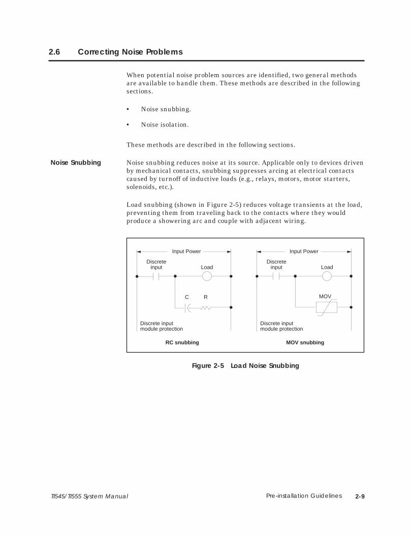
Noise snubbing reduces noise at its source. Applicable only to devices drivenby mechanical contacts, snubbing suppresses arcing at electrical contactscaused by turnoff of inductive loads (e.g., relays, motors, motor starters,solenoids, etc.).
Load snubbing (shown in Figure 2-5) reduces voltage transients at the load,preventing them from traveling back to the contacts where they wouldproduce a showering arc and couple with adjacent wiring.
Discreteinput Load
C R
Discrete inputmodule protection
RC snubbing
Input Power
Discreteinput Load
Discrete inputmodule protection
MOV snubbing
MOV
Input Power
Figure 2-5 Load Noise Snubbing
Noise Snubbing

2-10 Pre-installation Guidelines TI545/TI555 System Manual
Correcting Noise Problems (continued)
You can also use contact snubbing (shown in Figure 2-6) as an alternativetype of snubbing.
Both types of snubbing cause the physical devices to come on or go off moreslowly. The resistance-capacitance (RC) and metal oxide varistor (MOV)elements should have minimal effect on system timing; their time constantsare substantially less than one millisecond.
Discreteinput Load
CR
Discrete inputmodule protection
RC snubbing
Discreteinput Load
Discrete inputmodule protection
MOV snubbing
MOV
Input Power Input Power
Figure 2-6 Contact Noise Snubbing
NOTE: Noise snubbing shown in Figure 2-6 is built into the PPX:505-5518Relay Output module.

2-11TI545/TI555 System Manual Pre-installation Guidelines
The second approach to handling noise problems is to isolate the problemdevice and its wiring from the electronics and associated signal wiring. Youmay accomplish this by increasing the physical distance from some types ofnoisy devices. For extreme cases, electrostatic (metal) shielding may berequired. This is true for noise sources outside as well as inside themounting cabinet (NEMA-type recommended).
Two cases of field wiring warrant special attention; wiring which enters theharsh noise area to enable monitoring and control of those devices, and TTLor low-level (less than 24 V) wiring. In these cases, supplement the physicalseparation between control and noise-prone wiring with shielded,twisted-pair wiring (12 twists/ft) for the control signals.
Process transmitters should normally be grounded at the transmitter end.Use a single-point, shield ground as shown in Figure 2-7.
Shielding
Twisted Pair
Shielding
Transmitter
Single-point ground To Controller I/O
Figure 2-7 Grounding Shielded, Twisted Pair Cables
Noise Isolation
2-12 Pre-installation Guidelines TI545/TI555 System Manual
2.7 Wiring Considerations
Consider the following guidelines before installing any system or powerwiring.
• Always use the shortest possible single length cable.
• Avoid placing system and field wiring in the vicinity of high-energyand/or high frequency wiring.
• Keep field input wiring, output wiring, and all other types of wiring inthe panel physically separated when possible.
• Consider separating DC field wiring from AC field wiring whereverpossible.
• Avoid sharp bends to power and data cables. Use 7.6 cm (3 inches)radius on all bends.
• Ensure that a good low earth ground impedance of 0.1 ohm or lessexists for all components in the system.
• Use metal wireways and conduit when possible.
• Keep wire strippings from falling into modules, controllers, or bases.
• For long return lines to the power supply, do not use the same wire forinput and output modules. Using separate return wiring for thesemodules minimizes the voltage drop on the return lines of the inputconnections.
Guidelines
2-13TI545/TI555 System Manual Pre-installation Guidelines
2.8 Power System Grounding
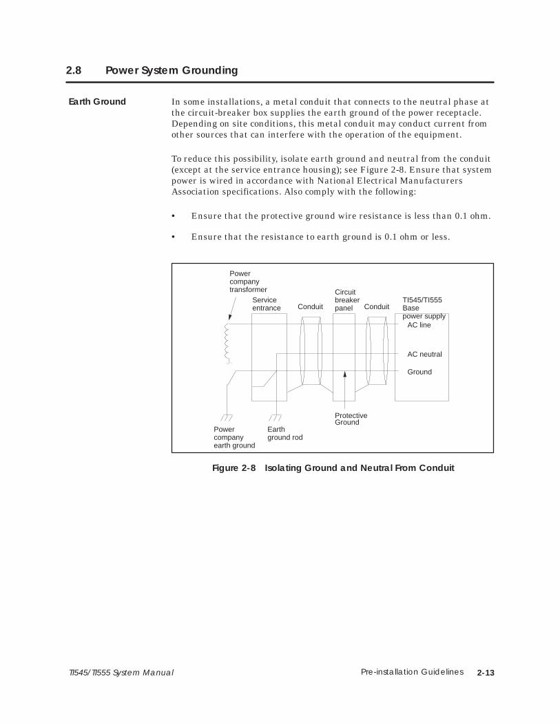
In some installations, a metal conduit that connects to the neutral phase atthe circuit-breaker box supplies the earth ground of the power receptacle.Depending on site conditions, this metal conduit may conduct current fromother sources that can interfere with the operation of the equipment.
To reduce this possibility, isolate earth ground and neutral from the conduit(except at the service entrance housing); see Figure 2-8. Ensure that systempower is wired in accordance with National Electrical ManufacturersAssociation specifications. Also comply with the following:
• Ensure that the protective ground wire resistance is less than 0.1 ohm.
• Ensure that the resistance to earth ground is 0.1 ohm or less.
Conduit Conduit
ProtectiveGround
Circuitbreakerpanel
TI545/TI555Basepower supply
AC line
AC neutral
Ground
Serviceentrance
Powercompanytransformer
Powercompanyearth ground
Earthground rod
Figure 2-8 Isolating Ground and Neutral From Conduit
Earth Ground

2-14 Pre-installation Guidelines TI545/TI555 System Manual
Power System Grounding (continued)
When installing the controller, ensure that noise is minimized by followingthese guidelines. Use the ground connection (Figure 2-9) to attach one endof a ground wire; attach the other end to a nearby grounding rod that meetsall electrical specifications required for an earth ground. Use the shortestpossible length of #8-gauge copper wire, or equivalent braided cable to makethe connection.
G
G
Figure 2-9 Grounding the TI545/TI555 Controller
If the controller is mounted in a cabinet or rack, use the same groundingprocedure. Ensure that a good cabinet or rack ground connection is achievedby removing existing paint and attaching a #8-gauge copper wire (orequivalent) using a bolt, washers, and nut as necessary. You can attach theother end of the wire to the same ground rod used to ground the controller.
Use particular care when establishing the ground connections. Thefollowing techniques will help to establish good electrical connections anddecrease noise interference:
• Terminate grounding braid and green wires at both ends with coppereye lugs to provide a good contact surface. Lugs should be crimped andsoldered.
• Use #10 copper bolts (or equivalent) for those fasteners providingelectrical connections to the single-point ground. This applies todevice-mounting bolts and braid termination bolts for subpanel anduser-supplied single points. Tapped holes for these fasteners are betterthan nut-bolt arrangements.
• Paints, coatings, and corrosion can prevent good electrical contact atground points. Remove these impediments in the area of contact anduse external toothed lock washers (star washers) to ensure goodcontinuity and low impedance. This practice should be used for allterminations — lug to subpanel, device to lug, device to subpanel,subpanel to conduit, etc. Examples of ground connections are shown inFigure 2-10.
Grounding theController
Grounding theCabinet or Rack
GroundConnections

2-15TI545/TI555 System Manual Pre-installation Guidelines
A good grounding system is essential for proper operation of thesystem. It is one of the most important considerations in planningyour installation. Failure to provide a good grounding system could result in death orserious injury to personnel and/or damage to equipment.
Ensure that you have a good grounding system when you installyour equipment.
Starwashers
Equipment Subpanel
Step 1
Step 3Step 2
Step 1
Step 2
To ground equipment directly to the sub-panel,follow these steps:
1. Remove the finish from the equipment atareas of contact.
2. Tighten the first nut.
3. Tighten the second nut.
You may need a lock washer to prevent the nutin Step 3 from backing off.
To attach ground leads to the sub-panel,follow these steps:
1. Remove the finish from the equipment atareas of contact.
2. Tighten the bolt.
Subpanelor user-suppliedsingle pointground
Starwashers
Groundbraidcopper lugs
Figure 2-10 Example of Ground Connection
CAUTION!
3-1TI545/TI555 System Manual Installing Series 505 System Hardware
Chapter 3
Installing Series 505 System Hardware
3.1 Overview of Installation Procedures 3-2. . . . . . . . . . . . . . . . . . . . . . . . . . . . . . . . . . . . . . . . . . . . . .
3.2 Series 505 Bases 3-3. . . . . . . . . . . . . . . . . . . . . . . . . . . . . . . . . . . . . . . . . . . . . . . . . . . . . . . . . . . . . . . . Description 3-3. . . . . . . . . . . . . . . . . . . . . . . . . . . . . . . . . . . . . . . . . . . . . . . . . . . . . . . . . . . . . . . . . . . . . Connecting Series 500 Bases 3-3. . . . . . . . . . . . . . . . . . . . . . . . . . . . . . . . . . . . . . . . . . . . . . . . . . . .
3.3 Rack Mounting Series 505 Base 3-4. . . . . . . . . . . . . . . . . . . . . . . . . . . . . . . . . . . . . . . . . . . . . . . . . . PPX:505–6516, 16-Slot Base 3-4. . . . . . . . . . . . . . . . . . . . . . . . . . . . . . . . . . . . . . . . . . . . . . . . . . . . . .
3.4 Panel Mounting Series 505 Bases 3-5. . . . . . . . . . . . . . . . . . . . . . . . . . . . . . . . . . . . . . . . . . . . . . . . . Series 505 Bases PPX:505–6516, PPX:505–6508, PPX:505–6504 3-5. . . . . . . . . . . . . . . . . . . . . . .
3.5 Installing Series 505 Power Supply 3-9. . . . . . . . . . . . . . . . . . . . . . . . . . . . . . . . . . . . . . . . . . . . . . . . Power Budget for Series 505 Base 3-9. . . . . . . . . . . . . . . . . . . . . . . . . . . . . . . . . . . . . . . . . . . . . . . . Power Supply Placement in Bases 3-9. . . . . . . . . . . . . . . . . . . . . . . . . . . . . . . . . . . . . . . . . . . . . . . . Installing and Removing the Power Supply 3-9. . . . . . . . . . . . . . . . . . . . . . . . . . . . . . . . . . . . . . .
3.6 Installing the TI545/TI555 CPU 3-11. . . . . . . . . . . . . . . . . . . . . . . . . . . . . . . . . . . . . . . . . . . . . . . . . . . . CPU/RBC Location in a Base 3-11. . . . . . . . . . . . . . . . . . . . . . . . . . . . . . . . . . . . . . . . . . . . . . . . . . . . . Installing and Removing the CPU 3-12. . . . . . . . . . . . . . . . . . . . . . . . . . . . . . . . . . . . . . . . . . . . . . . . CPU Battery 3-13. . . . . . . . . . . . . . . . . . . . . . . . . . . . . . . . . . . . . . . . . . . . . . . . . . . . . . . . . . . . . . . . . . . . Setting CPU Dipswitches 3-13. . . . . . . . . . . . . . . . . . . . . . . . . . . . . . . . . . . . . . . . . . . . . . . . . . . . . . . . . Using Port 1 3-14. . . . . . . . . . . . . . . . . . . . . . . . . . . . . . . . . . . . . . . . . . . . . . . . . . . . . . . . . . . . . . . . . . . . . Using Port 2 3-14. . . . . . . . . . . . . . . . . . . . . . . . . . . . . . . . . . . . . . . . . . . . . . . . . . . . . . . . . . . . . . . . . . . . . Setting Baud Rates 3-15. . . . . . . . . . . . . . . . . . . . . . . . . . . . . . . . . . . . . . . . . . . . . . . . . . . . . . . . . . . . . . Enabling Battery Backup 3-15. . . . . . . . . . . . . . . . . . . . . . . . . . . . . . . . . . . . . . . . . . . . . . . . . . . . . . . .
3.7 Installing Series 505 Remote Base Controller 3-16. . . . . . . . . . . . . . . . . . . . . . . . . . . . . . . . . . . . . . RBC Placement in Bases 3-16. . . . . . . . . . . . . . . . . . . . . . . . . . . . . . . . . . . . . . . . . . . . . . . . . . . . . . . . . Dipswitches 3-16. . . . . . . . . . . . . . . . . . . . . . . . . . . . . . . . . . . . . . . . . . . . . . . . . . . . . . . . . . . . . . . . . . . . Setting RS-232 Port Baud Rates (SW 2) 3-16. . . . . . . . . . . . . . . . . . . . . . . . . . . . . . . . . . . . . . . . . . . . Series 505 RBC SW 3 (Factory) Dipswitch Settings 3-17. . . . . . . . . . . . . . . . . . . . . . . . . . . . . . . . . . Output State Selection 3-17. . . . . . . . . . . . . . . . . . . . . . . . . . . . . . . . . . . . . . . . . . . . . . . . . . . . . . . . . . Installing and Removing Series 505 RBC 3-19. . . . . . . . . . . . . . . . . . . . . . . . . . . . . . . . . . . . . . . . . . Assigning RBC Base Numbers 3-19. . . . . . . . . . . . . . . . . . . . . . . . . . . . . . . . . . . . . . . . . . . . . . . . . . . . Series 505 RBC LED Display 3-20. . . . . . . . . . . . . . . . . . . . . . . . . . . . . . . . . . . . . . . . . . . . . . . . . . . . . . .
3.8 Installing Series 505 I/O Modules 3-21. . . . . . . . . . . . . . . . . . . . . . . . . . . . . . . . . . . . . . . . . . . . . . . . . Mixing I/O Modules 3-21. . . . . . . . . . . . . . . . . . . . . . . . . . . . . . . . . . . . . . . . . . . . . . . . . . . . . . . . . . . . . Installing and Removing I/O Modules 3-21. . . . . . . . . . . . . . . . . . . . . . . . . . . . . . . . . . . . . . . . . . . .

3-2 Installing Series 505 System Hardware TI545/TI555 System Manual
3.1 Overview of Installation Procedures
The following chart identifies the tasks for installing Series 505 systemhardware.
Install Base
• Rack mounting (Section 3.3) • Panel mounting (Section 3.4)
Install Power Supply (Section 3.5)
Install TI545/TI555 Controller (Section 3.6)
Install Remote Base Controller (Section 3.7)
Install I/O Modules (Section 3.8)
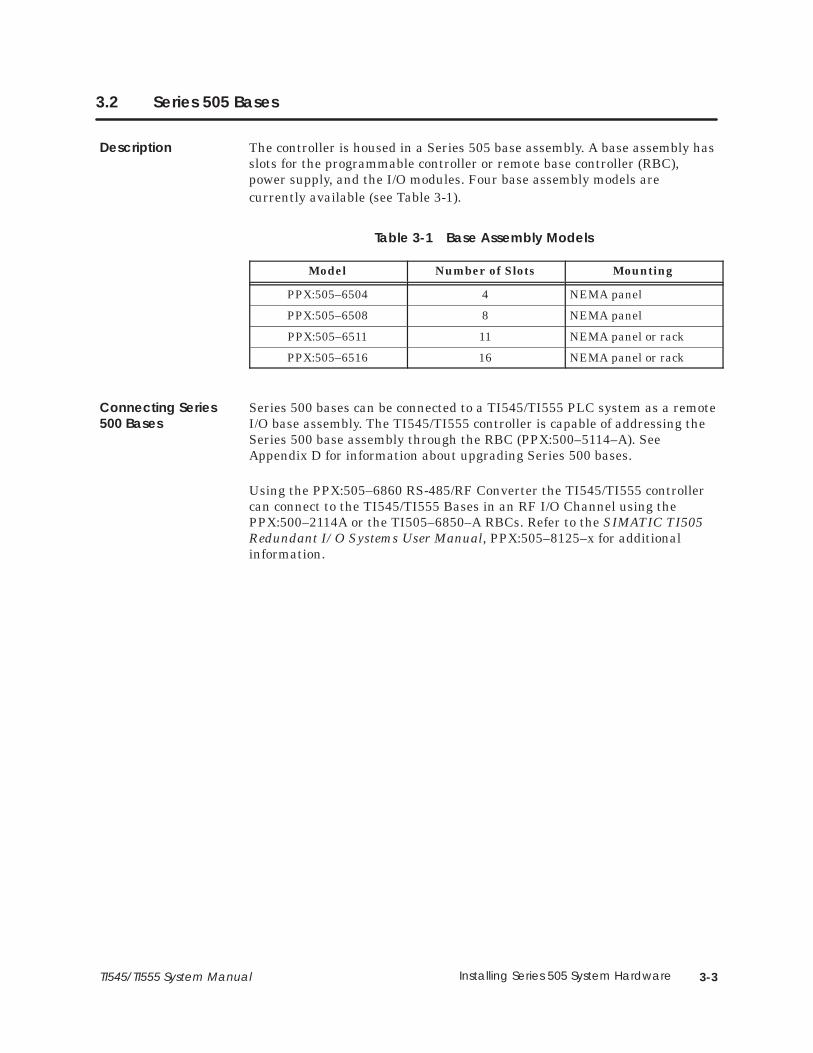
3-3TI545/TI555 System Manual Installing Series 505 System Hardware
3.2 Series 505 Bases
The controller is housed in a Series 505 base assembly. A base assembly hasslots for the programmable controller or remote base controller (RBC),power supply, and the I/O modules. Four base assembly models arecurrently available (see Table 3-1).
Table 3-1 Base Assembly Models
Model Number of Slots Mounting
PPX:505–6504 4 NEMA panel
PPX:505–6508 8 NEMA panel
PPX:505–6511 11 NEMA panel or rack
PPX:505–6516 16 NEMA panel or rack
Series 500 bases can be connected to a TI545/TI555 PLC system as a remoteI/O base assembly. The TI545/TI555 controller is capable of addressing theSeries 500 base assembly through the RBC (PPX:500–5114–A). SeeAppendix D for information about upgrading Series 500 bases.
Using the PPX:505–6860 RS-485/RF Converter the TI545/TI555 controllercan connect to the TI545/TI555 Bases in an RF I/O Channel using thePPX:500–2114A or the TI505–6850–A RBCs. Refer to the SIMATIC TI505Redundant I/O Systems User Manual, PPX:505–8125–x for additionalinformation.
Description
Connecting Series500 Bases

3-4 Installing Series 505 System Hardware TI545/TI555 System Manual
3.3 Rack Mounting Series 505 Base
Use the following steps, and Figure 3-1, for mounting the base in a standard19-inch rack.
1. Align two bracket holes with two screw holes located on the sides ofbase.
2. Secure each bracket to base with two screws installed through thebracket holes.
3. Position the base in the 19-inch rack. Depth of base is 7.99 inches(20.3 cm).
NOTE: There should be at least 6 inches (15.24 cm.) of clearance at the topand bottom of base for adequate airflow.
4. Align two bracket slots with two screw holes located on each side of the19-inch rack. See Figure 3-1.
5. Secure each bracket to the 19-inch rack with two screws installedthrough the the bracket slots. See Figure 3-1.
Figure 3-1 Mounting Base to Standard 19-inch Rack
PPX:505–6516,16-Slot Base

3-5TI545/TI555 System Manual Installing Series 505 System Hardware
3.4 Panel Mounting Series 505 Bases
Use the following steps for panel mounting in an NEMA enclosure.
1. Open NEMA enclosure door.
2. Drill four holes in sub-panel of NEMA enclosure with a #21 drill bit.Refer to Figure 3-2 through Figure 3-4 for screw-hole dimensions foreach base.
NOTE: There should be at least 6 inches (15.24 cm.) of clearance at the topand bottom of base for adequate airflow. The base depth is 7.99 inches(20.3 cm.).
PPX:505–6516 and PPX:505–651 1
0.64(16.26)
17.70(449.58)
0.64(16.26)
8.97(227.81)
1.47(37.31)
18.34(465.84)
10.47(265.94)
Note: in.(mm)
Figure 3-2 Screw-hole Dimensions for PPX:505–6516/6511 Bases
Series 505 BasesPPX:505–6516,PPX:505–6508,PPX:505–6504

3-6 Installing Series 505 System Hardware TI545/TI555 System Manual
Panel Mounting Series 505 Bases (continued)
PPX:505–6504
0.64(16.26)
0.64(16.26)
8.10(205.74)
10.47(265.94)
8.69(220.79)
8.97(227.81)
1.47(37.31)
Note: in.(mm)
Figure 3-3 Screw-hole Dimensions for PPX:505–6504 Bases
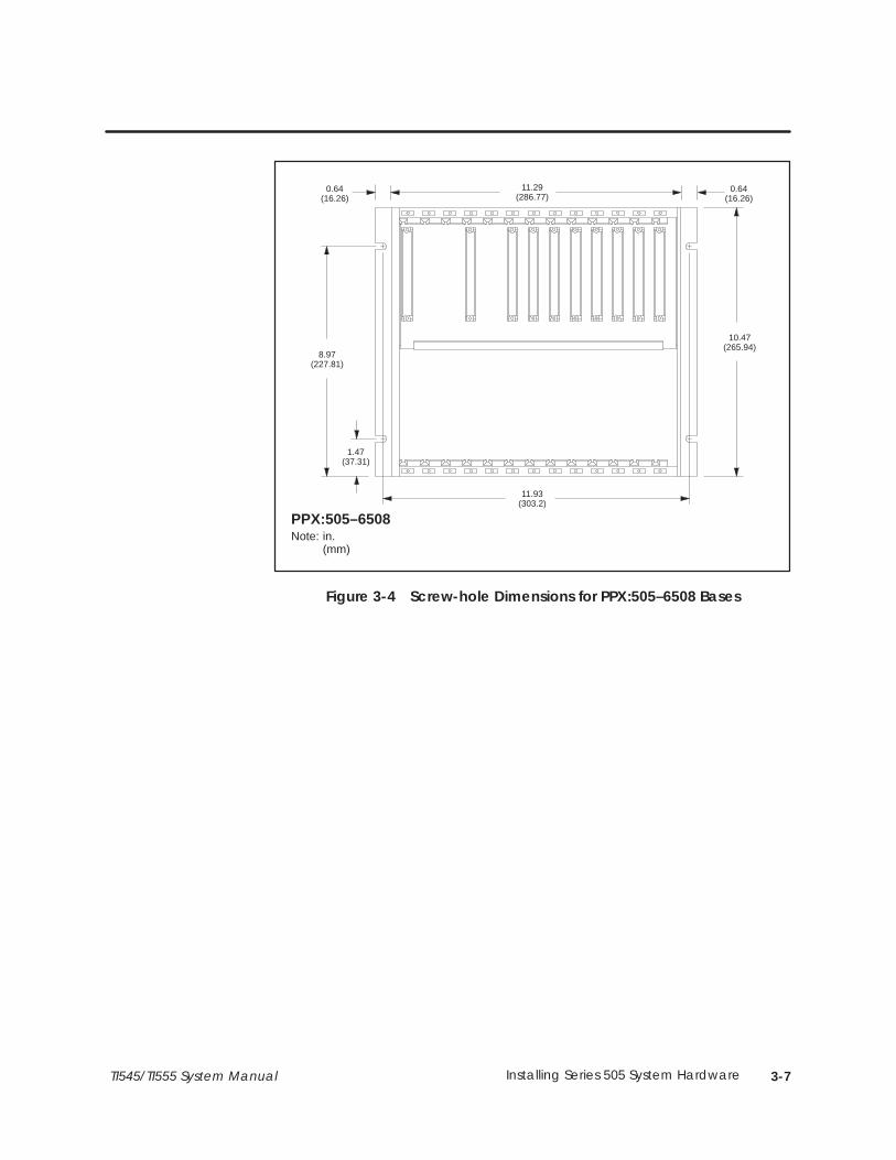
3-7TI545/TI555 System Manual Installing Series 505 System Hardware
PPX:505–6508
0.64(16.26)
11.29(286.77)
0.64(16.26)
10.47(265.94)
8.97(227.81)
1.47(37.31)
11.93(303.2)
Note: in.(mm)
Figure 3-4 Screw-hole Dimensions for PPX:505–6508 Bases
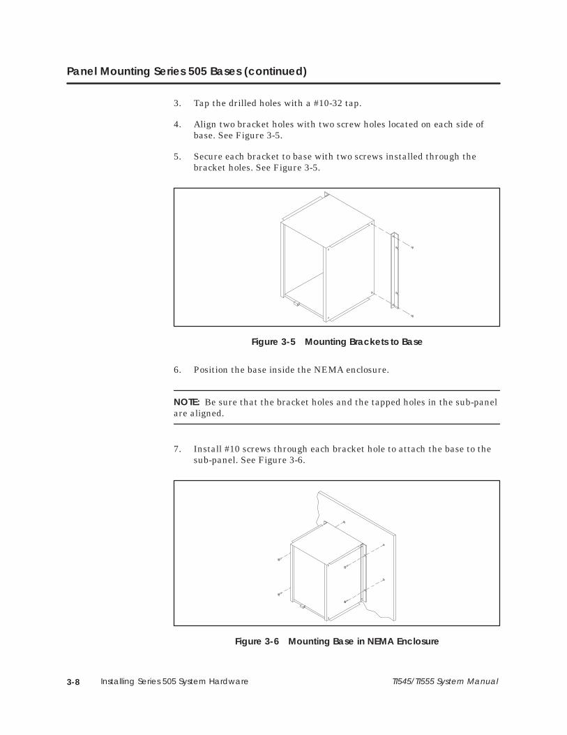
3-8 Installing Series 505 System Hardware TI545/TI555 System Manual
Panel Mounting Series 505 Bases (continued)
3. Tap the drilled holes with a #10-32 tap.
4. Align two bracket holes with two screw holes located on each side ofbase. See Figure 3-5.
5. Secure each bracket to base with two screws installed through thebracket holes. See Figure 3-5.
Figure 3-5 Mounting Brackets to Base
6. Position the base inside the NEMA enclosure.
NOTE: Be sure that the bracket holes and the tapped holes in the sub-panelare aligned.
7. Install #10 screws through each bracket hole to attach the base to thesub-panel. See Figure 3-6.
Figure 3-6 Mounting Base in NEMA Enclosure

3-9TI545/TI555 System Manual Installing Series 505 System Hardware
3.5 Installing Series 505 Power Supply
The total power consumption of all I/O modules (including theprogrammable controller and RBC) drawing power from a Series 505 powersupply must not exceed 55.0 W from the +5 VDC output and 3.75 W fromthe –5 VDC output. Refer to Appendix B for power consumption listings forthe controller and all currently available Series 505 I/O modules and RBCs.
See Figure 3-7 for power supply placement in Series 505 bases. The powersupply must always be installed in the left-most slot.
I/O
I/O
I/O
I/O
CPU/RBC
I/O
I/O
I/O
I/O
P/S
Figure 3-7 Series 505 Module Placement in Base
Use the steps that follow to install or remove the Series 505 base powersupply.
1. Disconnect power to the base.
Disable all power to the base before installing or removing anymodule.
Failure to do so could cause death or serious injury and/or damageto equipment.
Ensure that all power is disabled before you install or remove anymodule.
Power Budget forSeries 505 Base
Power SupplyPlacement in Bases
Installing andRemoving thePower Supply
WARNING!
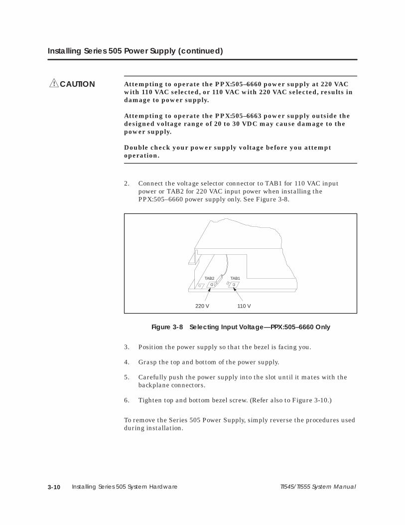
3-10 Installing Series 505 System Hardware TI545/TI555 System Manual
Installing Series 505 Power Supply (continued)
Attempting to operate the PPX:505–6660 power supply at 220 VACwith 110 VAC selected, or 110 VAC with 220 VAC selected, results indamage to power supply.
Attempting to operate the PPX:505–6663 power supply outside thedesigned voltage range of 20 to 30 VDC may cause damage to thepower supply.
Double check your power supply voltage before you attemptoperation.
2. Connect the voltage selector connector to TAB1 for 110 VAC inputpower or TAB2 for 220 VAC input power when installing thePPX:505–6660 power supply only. See Figure 3-8.
220 V 110 V
TAB1TAB2
Figure 3-8 Selecting Input Voltage—PPX:505–6660 Only
3. Position the power supply so that the bezel is facing you.
4. Grasp the top and bottom of the power supply.
5. Carefully push the power supply into the slot until it mates with thebackplane connectors.
6. Tighten top and bottom bezel screw. (Refer also to Figure 3-10.)
To remove the Series 505 Power Supply, simply reverse the procedures usedduring installation.
CAUTION!

3-11TI545/TI555 System Manual Installing Series 505 System Hardware
3.6 Installing the TI545/TI555 CPU
The CPU/RBC must always be installed in the second slot from the left(beside the power supply module), as shown in Figure 3-9.
I/O
I/O
I/O
I/O
I/O
I/O
I/O
I/O
P/S
CPU/RBC
Figure 3-9 Location of CPU/RBC in a Series 505 Base
Electronic equipment can be damaged by electrostatic discharge.
Ensure that personnel make contact with a grounded conductivepad and/or wear a grounded wrist strap when handling thecontroller cards or modules.
CPU/RBC Locationin a Base
CAUTION!
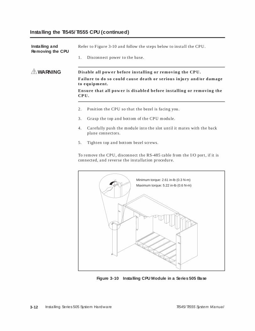
3-12 Installing Series 505 System Hardware TI545/TI555 System Manual
Installing the TI545/TI555 CPU (continued)
Refer to Figure 3-10 and follow the steps below to install the CPU.
1. Disconnect power to the base.
Disable all power before installing or removing the CPU.
Failure to do so could cause death or serious injury and/or damageto equipment.
Ensure that all power is disabled before installing or removing theCPU.
2. Position the CPU so that the bezel is facing you.
3. Grasp the top and bottom of the CPU module.
4. Carefully push the module into the slot until it mates with the backplane connectors.
5. Tighten top and bottom bezel screws.
To remove the CPU, disconnect the RS-485 cable from the I/O port, if it isconnected, and reverse the installation procedure.
Minimum torque: 2.61 in-lb (0.3 N-m)
Maximum torque: 5.22 in-lb (0.6 N-m)
Figure 3-10 Installing CPU Module in a Series 505 Base
Installing andRemoving the CPU
WARNING!
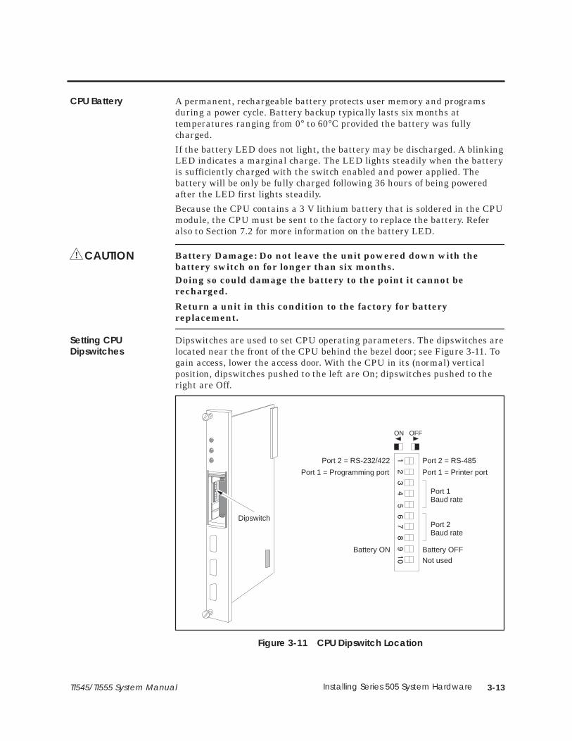
3-13TI545/TI555 System Manual Installing Series 505 System Hardware
A permanent, rechargeable battery protects user memory and programsduring a power cycle. Battery backup typically lasts six months attemperatures ranging from 0° to 60°C provided the battery was fullycharged.
If the battery LED does not light, the battery may be discharged. A blinkingLED indicates a marginal charge. The LED lights steadily when the batteryis sufficiently charged with the switch enabled and power applied. Thebattery will be only be fully charged following 36 hours of being poweredafter the LED first lights steadily.
Because the CPU contains a 3 V lithium battery that is soldered in the CPUmodule, the CPU must be sent to the factory to replace the battery. Referalso to Section 7.2 for more information on the battery LED.
Battery Damage: Do not leave the unit powered down with thebattery switch on for longer than six months.Doing so could damage the battery to the point it cannot berecharged.
Return a unit in this condition to the factory for batteryreplacement.
Dipswitches are used to set CPU operating parameters. The dipswitches arelocated near the front of the CPU behind the bezel door; see Figure 3-11. Togain access, lower the access door. With the CPU in its (normal) verticalposition, dipswitches pushed to the left are On; dipswitches pushed to theright are Off.
Dipswitch
OFFON
Port 2 = RS-485Port 2 = RS-232/422
Port 1 = Programming port Port 1 = Printer port
Port 1 Baud rate
Port 2 Baud rate
Battery OFFBattery ONNot used
Figure 3-11 CPU Dipswitch Location
CPU Battery
CAUTION!
Setting CPUDipswitches

3-14 Installing Series 505 System Hardware TI545/TI555 System Manual
Installing the TI545/TI555 CPU (continued)
Switch 2 selects Port 1 as, either a programming port, or a printer port; seeFigure 3-12 for port locations. This port uses a RS-232/RS-423 signalingprotocol and uses a RS-232 pinout arrangement with a RS-423 (+5 V) signallevel extending up to 50 feet. A modem may be used to increase the cabledistance.
• Setting Switch 2 to the left selects Port 1 as a programming port.
• Setting Switch 2 to the right selects Port 1 as a printer port.
Selection between RS-232/RS423 or RS-422/RS-485 is accomplished bycabling. If RS-422/RS-485 cabling is used, then dipswitch 1 selects betweenRS-422 and RS-485 (see Figure 3-11). The cable installation for RS-485 orRS-422 can include a 120-ohm termination resistor across the signalconductors at each end of the cable. The resistor provides a higher noiseimmunity and better long-distance communication (see Figure 3-12).
• RS-232/RS-423 connection for Operator Interface up to 50 feet.
• RS-422/RS-485 connection to 3300 feet (1 km).
Switch 1 is used as follows:
• When RS-232 or RS-422 cabling is used, set Switch 1 to the left.
• When RS-485 cabling is used, set Switch 1 to to the right. RS-485 usesa single twisted pair to transmit and receive data between theprogramming device and the CPU. Multiple CPUs or multipleprogramming devices (on this RS-485 link) are currently not supportedand should not be used.
Port 1
Port 2
Pin Signal3
9
5
8
2
DO+
DI+
GND
DO–
DI–
ControllerMale 9-Pin D Type
Port 2 (1)
RS-422 Port Pinouts
Pin Signal3
8
5
TX/RX+
TX/RX–
GND
ControllerMale 9-Pin D Type
Pin Signal1
2
3
4
5
RSD
RCV
XMT
DTR
GND
ControllerMale 9-Pin D Type
Port 1RS-232 Port Pinouts
6 DSR
7 RTS
8 CTS
Pin Signal2
3
5
RCV
XMT
GND
Controller
Port 2 (1)
RS-232 Port Pinouts
Male 9-Pin D Type
Port 2 (2)
RS-485 Port Pinouts
(1) Dipswitch 1 is ON(2) Dipswitch 1 is OFF
Termination resistors can beused for higher noise immunityand better long-distancecommunication.
Figure 3-12 TI545/TI555 CPU Port Locations
Using Port 1
Using Port 2
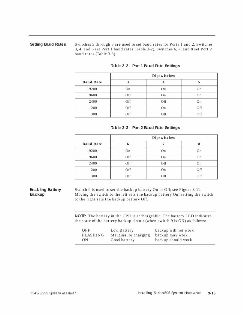
3-15TI545/TI555 System Manual Installing Series 505 System Hardware
Switches 3 through 8 are used to set baud rates for Ports 1 and 2. Switches3, 4, and 5 set Port 1 baud rates (Table 3-2). Switches 6, 7, and 8 set Port 2baud rates (Table 3-3).
Table 3-2 Port 1 Baud Rate Settings
Dipswitches
Baud Rate 3 4 5
19200 On On On
9600 Off On On
2400 Off Off On
1200 Off On Off
300 Off Off Off
Table 3-3 Port 2 Baud Rate Settings
Dipswitches
Baud Rate 6 7 8
19200 On On On
9600 Off On On
2400 Off Off On
1200 Off On Off
300 Off Off Off
Switch 9 is used to set the backup battery On or Off; see Figure 3-11.Moving the switch to the left sets the backup battery On; setting the switchto the right sets the backup battery Off.
NOTE: The battery in the CPU is rechargeable. The battery LED indicatesthe state of the battery backup circuit (when switch 9 is ON) as follows:
OFF Low Battery backup will not workFLASHING Marginal or charging backup may workON Good battery backup should work
Setting Baud Rates
Enabling BatteryBackup

3-16 Installing Series 505 System Hardware TI545/TI555 System Manual
3.7 Installing Series 505 Remote Base Controller
The RBC must always be installed in the second slot from the left (adjacentto the power supply module) in a remote base.
There are two dipswitches, SW 2 and SW 3, located on the components sideof the RBC. SW 2 (Figure 3-13) is used to set baud rates. SW 3 is afactory-use-only switch.
1 2 3 4
Front bezel
Off
On
SW 2
Figure 3-13 RBC Dipswitch Location
Dipswitch SW 2 is used to set baud rates for the RBC RS-232 port. TheRS-232 port is used to program the controller or to troubleshoot from aremote I/O base.
See Figure 3-13 for positions of SW 2 on the board; refer to Table 3-4 forindividual dipswitch settings.
Table 3-4 RBC SW 2 (RS-232 Port) Baud Rate Settings
Dipswitch
Baud Rate 1 2 3 4
19200 On (1) On (1) Off (0) On (1)
9600 On (1) On (1) On (1) On (1)
2400 Off (0) On (1) On (1) On (1)
1200 On (1) Off (0) On (1) On (1)
300 Off (0) Off (0) On (1) On (1)
RBC Placement inBases
Dipswitches
Setting RS-232 PortBaud Rates (SW 2)
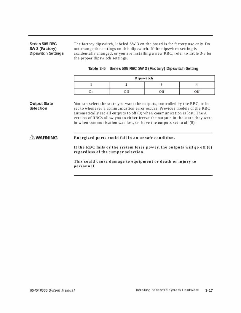
3-17TI545/TI555 System Manual Installing Series 505 System Hardware
The factory dipswitch, labeled SW 3 on the board is for factory use only. Donot change the settings on this dipswitch. If the dipswitch setting isaccidentally changed, or you are installing a new RBC, refer to Table 3-5 forthe proper dipswitch settings.
Table 3-5 Series 505 RBC SW 3 (Factory) Dipswitch Setting
Dipswitch
1 2 3 4
On Off Off Off
You can select the state you want the outputs, controlled by the RBC, to beset to whenever a communication error occurs. Previous models of the RBCautomatically set all outputs to off (0) when communication is lost. The Aversion of RBCs allow you to either freeze the outputs in the state they werein when communication was lost, or have the outputs set to off (0).
Energized parts could fail in an unsafe condition.
If the RBC fails or the system loses power, the outputs will go off (0)regardless of the jumper selection.
This could cause damage to equipment or death or injury topersonnel.
Series 505 RBCSW 3 (Factory)Dipswitch Settings
Output StateSelection
WARNING!
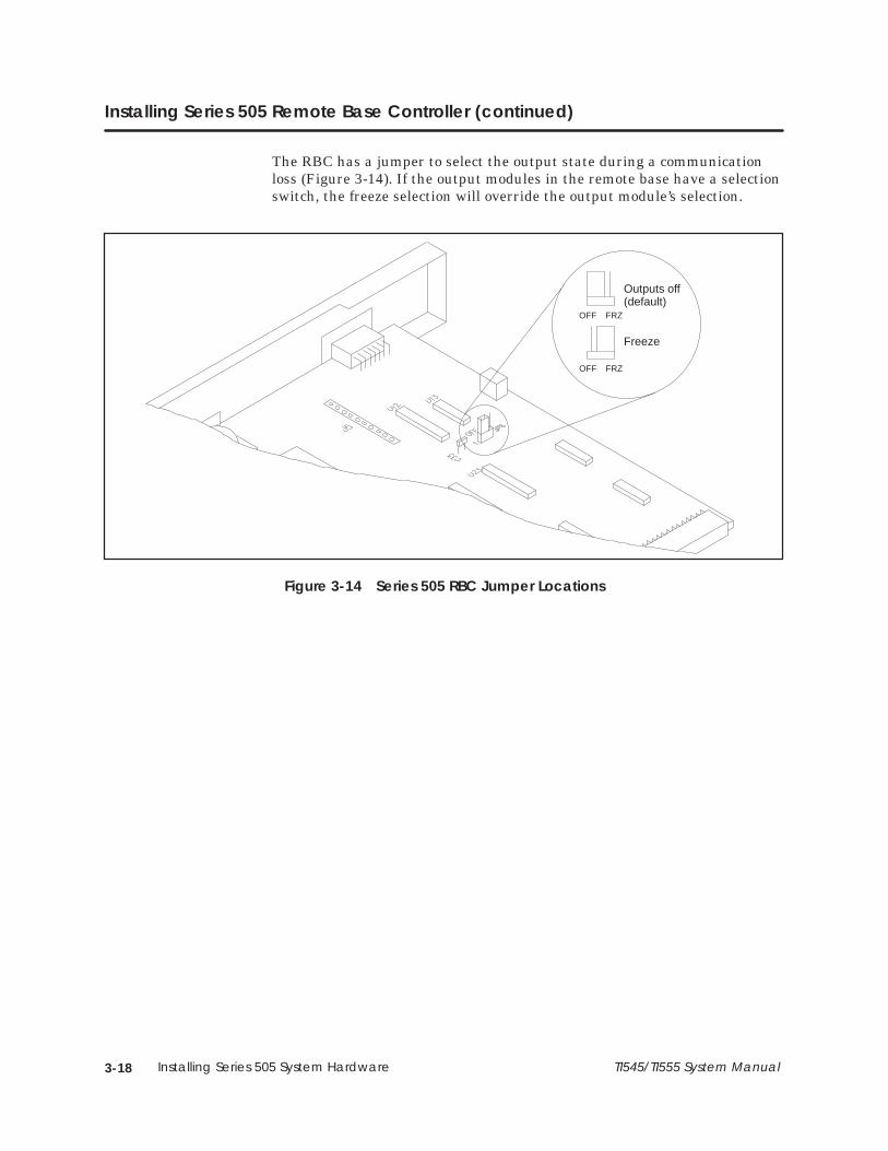
3-18 Installing Series 505 System Hardware TI545/TI555 System Manual
Installing Series 505 Remote Base Controller (continued)
The RBC has a jumper to select the output state during a communicationloss (Figure 3-14). If the output modules in the remote base have a selectionswitch, the freeze selection will override the output module’s selection.
Outputs off(default)
Freeze
OFF FRZ
OFF FRZ
Figure 3-14 Series 505 RBC Jumper Locations

3-19TI545/TI555 System Manual Installing Series 505 System Hardware
Use the following steps to install and remove a Series 505 RBC.
The RBC can be damaged by electrostatic discharge.
Ensure that personnel make contact with a grounded conductivepad and/or wear a grounded wrist strap when handling the RBC.
1. Disconnect power to the base.
Disable all power to the base before installing or removing theRBC.
Failure to do so could cause death or serious injury and/or damageto equipment.
To prevent disruption of the I/O channel, disconnect the RS-485cable before removing or installing an RBC.
2. Position the RBC so that the bezel is facing you.
3. Grasp the top and bottom of the RBC.
4. Carefully push the RBC into the slot until it mates with the back planeconnectors.
5. Tighten top and bottom bezel screws.
To remove the RBC module, complete these steps.
1. If attached, remove cables from the front of the RBC.
2. To complete the removal of the RBC module, simply reverse proceduresused during installation.
A base thumbwheel is used to assign a base number to the RBC for systemidentification. If you are using more than one RBC, each RBC must beuniquely numbered. Base numbers are the same as the thumbwheelnumber except for base 0, which is reserved for local base assignment andcannot be used by Series 505 RBCs.
Installing andRemovingSeries 505 RBC
CAUTION!
WARNING!
Assigning RBCBase Numbers

3-20 Installing Series 505 System Hardware TI545/TI555 System Manual
Installing Series 505 Remote Base Controller (continued)
Control devices can fail in an unsafe condition that could result indeath or serious injury and/or damage to equipment.
Do not change the base thumbwheel numbers when the system isoperating. This may cause the base to be logged off the system.
When the base is logged off the system, all discrete outputs will beturned off, analog outputs will be frozen, and word and discreteinputs will go to 0.
The display at the top of the module (see Figure 3-15) indicates the status ofthe Series 505 RBC. Status is displayed in integer format; see Table 3-6 fordefinitions of the displays.
Table 3-6 Series 505 RBC LED Messages
Display Definitions
0 RBC Good
1 Self Diagnostics Failure
2 Module Mismatch
3 I/O Communication Time Out
4 RAM Parity Error
5 Standby, No Configuration
6 Address Mismatch
7 Communication Good, No Configuration
8 Watchdog Time Out
C Standby, Configuration
Base Thumbwheel
LED Display
RS-232 port (male)
I/O port (female)
Figure 3-15 Series 505 Remote Base Controller
WARNING!
Series 505 RBCLED Display
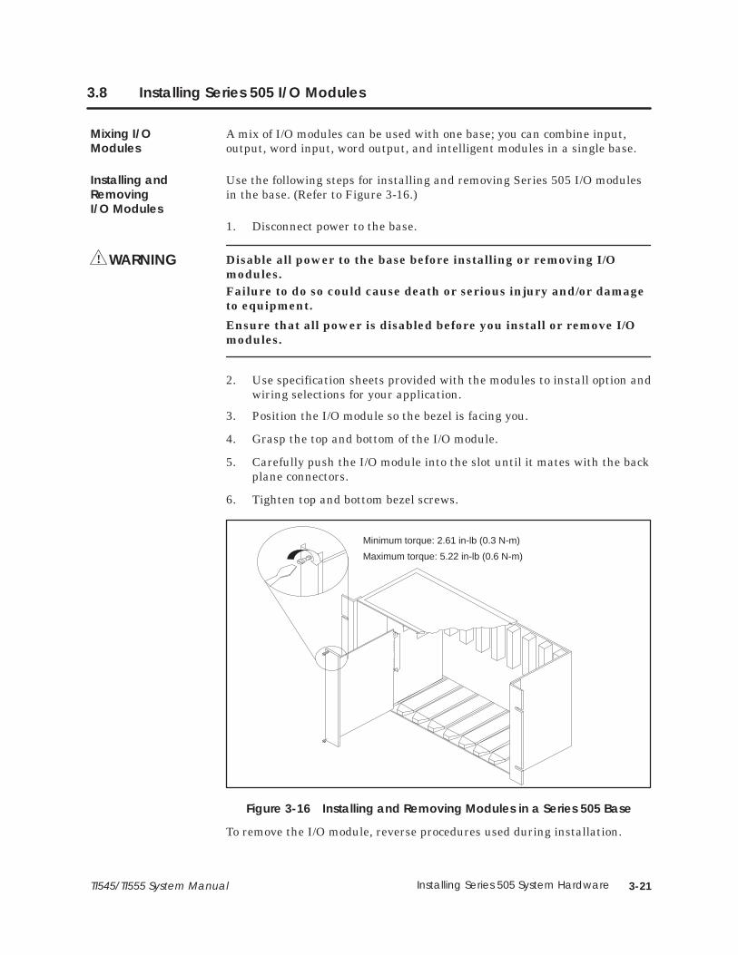
3-21TI545/TI555 System Manual Installing Series 505 System Hardware
3.8 Installing Series 505 I/O Modules
A mix of I/O modules can be used with one base; you can combine input,output, word input, word output, and intelligent modules in a single base.
Use the following steps for installing and removing Series 505 I/O modulesin the base. (Refer to Figure 3-16.)
1. Disconnect power to the base.
Disable all power to the base before installing or removing I/Omodules.Failure to do so could cause death or serious injury and/or damageto equipment.
Ensure that all power is disabled before you install or remove I/Omodules.
2. Use specification sheets provided with the modules to install option andwiring selections for your application.
3. Position the I/O module so the bezel is facing you.
4. Grasp the top and bottom of the I/O module.
5. Carefully push the I/O module into the slot until it mates with the backplane connectors.
6. Tighten top and bottom bezel screws.
Minimum torque: 2.61 in-lb (0.3 N-m)
Maximum torque: 5.22 in-lb (0.6 N-m)
Figure 3-16 Installing and Removing Modules in a Series 505 Base
To remove the I/O module, reverse procedures used during installation.
Mixing I/OModules
Installing andRemovingI/O Modules
WARNING!
4-1Cabling and Wiring the SystemTI545/TI555 System Manual
Chapter 4
Cabling and Wiring the System
4.1 Connecting Input Power 4-2. . . . . . . . . . . . . . . . . . . . . . . . . . . . . . . . . . . . . . . . . . . . . . . . . . . . . . . . Guidelines 4-2. . . . . . . . . . . . . . . . . . . . . . . . . . . . . . . . . . . . . . . . . . . . . . . . . . . . . . . . . . . . . . . . . . . . . . Wiring Power Supply 4-2. . . . . . . . . . . . . . . . . . . . . . . . . . . . . . . . . . . . . . . . . . . . . . . . . . . . . . . . . . . .
4.2 Cable Routing 4-4. . . . . . . . . . . . . . . . . . . . . . . . . . . . . . . . . . . . . . . . . . . . . . . . . . . . . . . . . . . . . . . . . . Guidelines 4-4. . . . . . . . . . . . . . . . . . . . . . . . . . . . . . . . . . . . . . . . . . . . . . . . . . . . . . . . . . . . . . . . . . . . . . Cable Routing Methods 4-4. . . . . . . . . . . . . . . . . . . . . . . . . . . . . . . . . . . . . . . . . . . . . . . . . . . . . . . . . Under-Floor Routing 4-5. . . . . . . . . . . . . . . . . . . . . . . . . . . . . . . . . . . . . . . . . . . . . . . . . . . . . . . . . . . . . In-Ceiling Routing 4-5. . . . . . . . . . . . . . . . . . . . . . . . . . . . . . . . . . . . . . . . . . . . . . . . . . . . . . . . . . . . . . . Surface Duct Routing 4-5. . . . . . . . . . . . . . . . . . . . . . . . . . . . . . . . . . . . . . . . . . . . . . . . . . . . . . . . . . . Mounting the Tap or Terminal Block 4-5. . . . . . . . . . . . . . . . . . . . . . . . . . . . . . . . . . . . . . . . . . . . . .
4.3 Installing Remote I/O Cables 4-6. . . . . . . . . . . . . . . . . . . . . . . . . . . . . . . . . . . . . . . . . . . . . . . . . . . . Cabling Options 4-6. . . . . . . . . . . . . . . . . . . . . . . . . . . . . . . . . . . . . . . . . . . . . . . . . . . . . . . . . . . . . . . . Trunk and Drop Lines 4-6. . . . . . . . . . . . . . . . . . . . . . . . . . . . . . . . . . . . . . . . . . . . . . . . . . . . . . . . . . . . User-Supplied Equipment 4-7. . . . . . . . . . . . . . . . . . . . . . . . . . . . . . . . . . . . . . . . . . . . . . . . . . . . . . . . Mounting the Terminal Block 4-7. . . . . . . . . . . . . . . . . . . . . . . . . . . . . . . . . . . . . . . . . . . . . . . . . . . . . Programmable Controller and RBC Drop Lines 4-7. . . . . . . . . . . . . . . . . . . . . . . . . . . . . . . . . . . . Preparing Cables (for Drop Lines) 4-8. . . . . . . . . . . . . . . . . . . . . . . . . . . . . . . . . . . . . . . . . . . . . . . . Connecting a CPU Drop Line 4-9. . . . . . . . . . . . . . . . . . . . . . . . . . . . . . . . . . . . . . . . . . . . . . . . . . . . Connecting the RBC Drop Line 4-11. . . . . . . . . . . . . . . . . . . . . . . . . . . . . . . . . . . . . . . . . . . . . . . . . . Connecting Terminal Block Trunk Lines 4-12. . . . . . . . . . . . . . . . . . . . . . . . . . . . . . . . . . . . . . . . . . . Alternate Cables 4-13. . . . . . . . . . . . . . . . . . . . . . . . . . . . . . . . . . . . . . . . . . . . . . . . . . . . . . . . . . . . . . . Configuration Requirements 4-14. . . . . . . . . . . . . . . . . . . . . . . . . . . . . . . . . . . . . . . . . . . . . . . . . . . . . Preparing Trunk Line Cables 4-16. . . . . . . . . . . . . . . . . . . . . . . . . . . . . . . . . . . . . . . . . . . . . . . . . . . . . Connecting Trunk Line to Terminal Blocks 4-17. . . . . . . . . . . . . . . . . . . . . . . . . . . . . . . . . . . . . . . . .
4.4 Connecting Modems 4-18. . . . . . . . . . . . . . . . . . . . . . . . . . . . . . . . . . . . . . . . . . . . . . . . . . . . . . . . . . . Overview 4-18. . . . . . . . . . . . . . . . . . . . . . . . . . . . . . . . . . . . . . . . . . . . . . . . . . . . . . . . . . . . . . . . . . . . . . . Dedicated Line Operation 4-19. . . . . . . . . . . . . . . . . . . . . . . . . . . . . . . . . . . . . . . . . . . . . . . . . . . . . . Dial-up Phone Line Operation 4-19. . . . . . . . . . . . . . . . . . . . . . . . . . . . . . . . . . . . . . . . . . . . . . . . . . .
4.5 Connecting a Printer 4-20. . . . . . . . . . . . . . . . . . . . . . . . . . . . . . . . . . . . . . . . . . . . . . . . . . . . . . . . . . . . Overview 4-20. . . . . . . . . . . . . . . . . . . . . . . . . . . . . . . . . . . . . . . . . . . . . . . . . . . . . . . . . . . . . . . . . . . . . . .

Cabling and Wiring the System4-2 TI545/TI555 System Manual
4.1 Connecting Input Power
To connect the Series 505 power supply, and the Series 500 remote I/O baseto the external power source, follow these guidelines.
• Use 14 AWG solid or stranded wire. If you use stranded wire, the wireshould be twisted and trimmed.
• Strip insulation back 0.40 inches (10mm).
• Insert the wires fully into the terminal block so that the insulationbutts against the block.
Use the following steps for connecting input power to the power supply. SeeFigure 4-1.
1. Disconnect power to the base.
Disable all power before attempting the wiring procedures.
Failure to do so could cause death or serious injury and/or damageto equipment.
Ensure that all power is disabled before attempting the wiringprocedures.
2. Loosen three power connector screws.
3. Connect wires as appropriate for your power supply module.
Model PPX:505–6660A: insert ground, neutral, and AC line wires intosocket on the power supply. This power supply requires 110 or 220 VAC.
Ensure that PPX:505–6660A power supply is set to operate on 110VAC or 220 VAC to match the input power. See Chapter 3 forselecting voltage for this power supply.
Attempting to operate the power supply at 220 VAC with 110 VACselected, or 110 VAC with 220 VAC selected, will result in damage tothe power supply.
Double check your power supply voltage before you attempt theoperation.
Model PPX:505–6663: insert chassis ground, DC–, and DC+ line wiresinto socket on the power supply. This power supply requires 24 VDC.
Guidelines
WiringPower Supply
WARNING!
CAUTION!
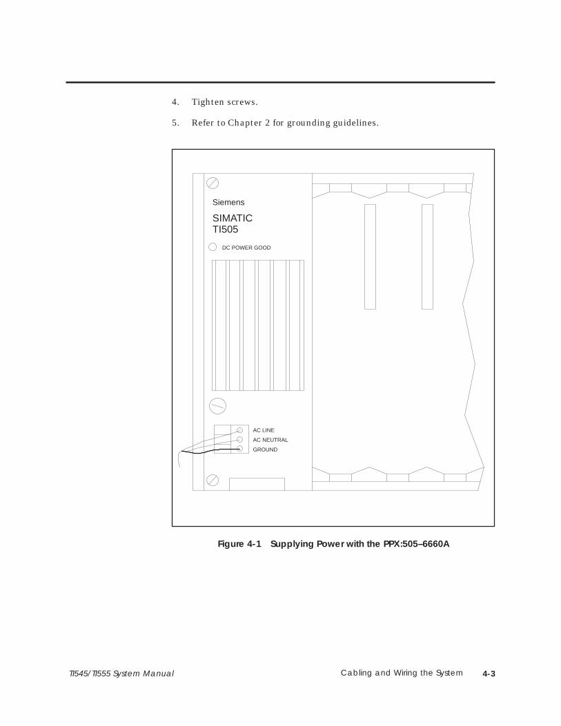
4-3Cabling and Wiring the SystemTI545/TI555 System Manual
4. Tighten screws.
5. Refer to Chapter 2 for grounding guidelines.
DC POWER GOOD
AC LINE
AC NEUTRAL
GROUND
Siemens
SIMATICTI505
Figure 4-1 Supplying Power with the PPX:505–6660A
Cabling and Wiring the System4-4 TI545/TI555 System Manual
4.2 Cable Routing
Follow these suggestions when planning your cable routing.
• Allow for system growth. Provide for attachment of future I/O bases byrouting cable through all possible areas of plant expansion.
• The TI545/TI555 can have a trunk line (attached to its I/O) thatextends up to 3300 feet (1000 m) using RS-485 (twisted pair) cables.
• Take steps to bypass or eliminate noise sources to reduce system dataerror rates. The following are common sources of electrical noise.
� Power distribution mains
� Arcing motors
� Fluorescent lighting
� Undesired signal transfer between adjacent circuits
� Poor terminations of cable connector
• Do not allow the trunk cable to come into contact with any otherelectrical conductor.
• If cabling is installed inside a conduit, the conduit should be groundedaccording to applicable electrical codes.
• Maintain a minimum of 3 feet (0.91 m) between trunk lines and thefollowing noise sources.
� Power lines
� Electric motors and motor starters
� Generators
� Electric welders
The type of routing is usually determined by the type of building in whichthe cables are being installed. Any combination of the following may be usedto route the cables: under-floor, in-ceiling, or surface duct.
NOTE: Electrical and fire safety must be considered in planning theinstallation. Modern codes seek to limit the hazard of cable installations asa means of propagating fire and smoke. In order to ensure a proper level ofsafety compliance, observe local installation code practices and guidelines.
Guidelines
Cable RoutingMethods

4-5Cabling and Wiring the SystemTI545/TI555 System Manual
In under-floor routing, the cable can be enclosed in ducts or, with raisedflooring, in the open air.
• Duct systems are better protected against unauthorized taps orterminal blocks, but expansion is more difficult and expensive thanwith open air systems.
• Open air systems provide more freedom of access, and allow maximumsystem expansion and flexibility.
For in-ceiling routing, cables are usually supported in troughs or with hooksand clamps every 10 or 15 feet (3.05 or 4.57 m).
Some advantages of in-ceiling routing follow:
• Flexibility.
• Low cost installation.
• Accessibility of cabling.
Some disadvantages of in-ceiling routing are:
• Collection of dust and other debris in ceilings.
• Hazardous working conditions in ceilings.
• Impracticality for buildings without drop ceilings.
Surface ducting is usually installed along baseboards or attached to walls atdesktop height. While surface ducting ordinarily protects cables from bothphysical and electro-magnetic (E/M) effects, it usually requires I/O bases tobe positioned near a wall.
NOTE: Consult your cable vendor for proper cable-pulling techniques so thatno kinks occur in the cable during installation.
Installation procedures for mounting the tap or terminal block depend uponthe cable installation technique used. Refer to mounting instructionsprovided by the tap or terminal block vendor.
Under-FloorRouting
In-Ceiling Routing
Surface DuctRouting
Mounting the Tapor Terminal Block

Cabling and Wiring the System4-6 TI545/TI555 System Manual
4.3 Installing Remote I/O Cables
Effective with Firmware Release 3.0 the TI545/TI555 provides two cablingoptions for the remote I/O system:
• Non-redundant I/O cabling using twisted pair (RS-485) media.
• Redundant I/O cabling using coaxial (RF) media.
This manual describes the twisted pair media. If you are installing aRedundant I/O system follow the instructions in the SIMATIC TI505Redundant I/O Systems User Manual, PPX:505–8125–2.
Use RS-485 cabling to install your trunk and drop lines after you haveinstalled other system hardware items.
Figure 4-2 shows a typical application. The following sections provideinformation on cabling the TI545/TI555 controller and RBCs designed forRS-485 cables. These models are as follows:
• Programmable Controller — PPX:545–1102, PPX:555–1101, orPPX:555–1102.
• RBC — PPX:505–6851–A for Series 505 bases.
• RBC — PPX:500–5114–A for Series 500 bases (see Appendix D).
TT
Trunk Lines
Drop Lines
Drop Line
T = Terminal Block
T
RemoteBase
RemoteBase
LocalBase
Figure 4-2 Trunk and Drop Line Example
Cabling Options
Trunk and DropLines

4-7Cabling and Wiring the SystemTI545/TI555 System Manual
User-supplied components are listed below:
• RS-485 cables.
• Taps (terminal blocks).
• 9-Pin D-connectors (male) and shell.
• Terminal lugs.
Installation procedures for mounting the terminal block depend upon thecable installation technique used. Refer to mounting instructions providedby the terminal block vendor for additional information.
The cable that connects the programmable controller and RBC to a terminalblock is called a drop line (Figure 4-2). Belden� cable type 9271 and 9182should be used for all drop lines.
NOTE: If the trunk line is Belden cable type 9182, the drop line must beBelden cable type 9182.
If the trunk line is Belden cable type 9860 or 9271, the drop line can beBelden cable type 9271 or 9182.
User-SuppliedEquipment
Mounting theTerminal Block
ProgrammableController andRBC Drop Lines

Cabling and Wiring the System4-8 TI545/TI555 System Manual
Installing Remote I/O Cables (continued)
Use the following procedures to prepare drop line cables to connect theprogrammable controller and RBC to terminal blocks:
1. Strip back 1.50 inches (3.8 cm) of the sleeving on one end of the cable.There are three wires when the sleeving is stripped back; two wireshave color coded insulation jackets and one is bare.
2. Remove 0.13 in. (0.33 cm) of each color coded insulation jacket toexpose the bare wires.
NOTE: One wire should already be bare.
3. Install the cable wires to a 9-pin D-connector according to directionsprovided by the connector vendor.
NOTE: Install the wire without insulation to pin #5 of the 9-pin D-connector.Install the wires with the color-coded insulation to pins #3 and #8. It does not matter which wire is installed to pin #3 or #8, but all connectorsmust be installed identically. See Figure 4-3 for pin-out information.
Ground (5)
Signal (3)Signal (8)
6 1
95
Figure 4-3 9-Pin I/O Female D-Connector Pinout
Preparing Cables(for Drop Lines)
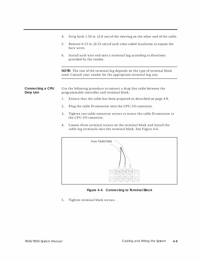
4-9Cabling and Wiring the SystemTI545/TI555 System Manual
4. Strip back 1.50 in. (3.8 cm) of the sleeving on the other end of the cable.
5. Remove 0.13 in. (0.33 cm) of each color-coded insulation to expose thebare wires.
6. Install each wire end onto a terminal lug according to directionsprovided by the vendor.
NOTE: The size of the terminal lug depends on the type of terminal blockused. Consult your vendor for the appropriate terminal lug size.
Use the following procedure to connect a drop line cable between theprogrammable controller and terminal block.
1. Ensure that the cable has been prepared as described on page 4-8.
2. Plug the cable D-connector onto the CPU I/O connector.
3. Tighten two cable connector screws to secure the cable D-connector tothe CPU I/O connector.
4. Loosen three terminal screws on the terminal block and install thecable lug terminals onto the terminal block. See Figure 4-4.
From TI545/TI555
Figure 4-4 Connecting to Terminal Block
5. Tighten terminal block screws.
Connecting a CPUDrop Line
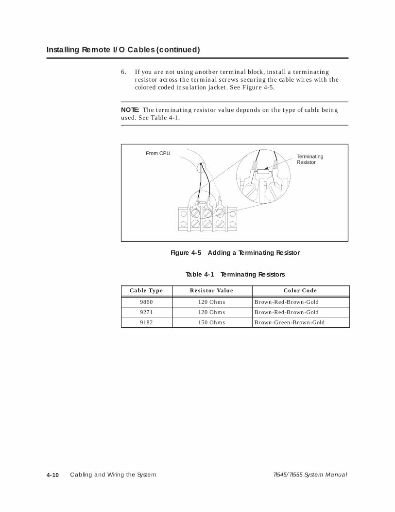
Cabling and Wiring the System4-10 TI545/TI555 System Manual
Installing Remote I/O Cables (continued)
6. If you are not using another terminal block, install a terminatingresistor across the terminal screws securing the cable wires with thecolored coded insulation jacket. See Figure 4-5.
NOTE: The terminating resistor value depends on the type of cable beingused. See Table 4-1.
From CPUTerminatingResistor
Figure 4-5 Adding a Terminating Resistor
Table 4-1 Terminating Resistors
Cable Type Resistor Value Color Code
9860 120 Ohms Brown-Red-Brown-Gold
9271 120 Ohms Brown-Red-Brown-Gold
9182 150 Ohms Brown-Green-Brown-Gold
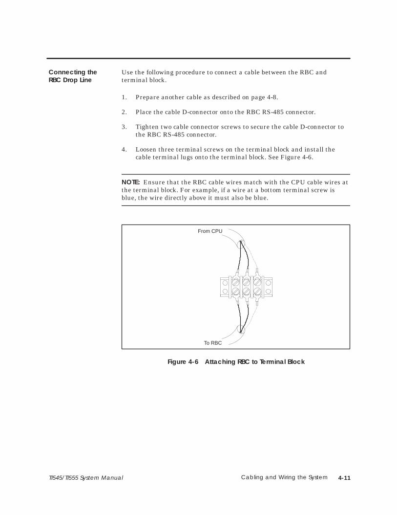
4-11Cabling and Wiring the SystemTI545/TI555 System Manual
Use the following procedure to connect a cable between the RBC andterminal block.
1. Prepare another cable as described on page 4-8.
2. Place the cable D-connector onto the RBC RS-485 connector.
3. Tighten two cable connector screws to secure the cable D-connector tothe RBC RS-485 connector.
4. Loosen three terminal screws on the terminal block and install thecable terminal lugs onto the terminal block. See Figure 4-6.
NOTE: Ensure that the RBC cable wires match with the CPU cable wires atthe terminal block. For example, if a wire at a bottom terminal screw isblue, the wire directly above it must also be blue.
To RBC
From CPU
Figure 4-6 Attaching RBC to Terminal Block
Connecting theRBC Drop Line
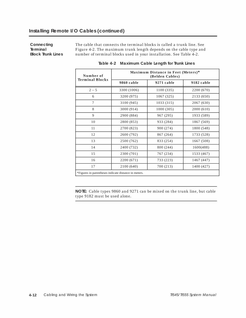
Cabling and Wiring the System4-12 TI545/TI555 System Manual
Installing Remote I/O Cables (continued)
The cable that connects the terminal blocks is called a trunk line. SeeFigure 4-2. The maximum trunk length depends on the cable type andnumber of terminal blocks used in your installation. See Table 4-2.
Table 4-2 Maximum Cable Length for Trunk Lines
Number ofTerminal Blocks
Maximum Distance in Feet (Meters)*(Belden Cables)
Terminal Blocks9860 cable 9271 cable 9182 cable
2 – 5 3300 (1006) 1100 (335) 2200 (670)
6 3200 (975) 1067 (325) 2133 (650)
7 3100 (945) 1033 (315) 2067 (630)
8 3000 (914) 1000 (305) 2000 (610)
9 2900 (884) 967 (295) 1933 (589)
10 2800 (853) 933 (284) 1867 (569)
11 2700 (823) 900 (274) 1800 (548)
12 2600 (792) 867 (264) 1733 (528)
13 2500 (762) 833 (254) 1667 (508)
14 2400 (732) 800 (244) 1600(488)
15 2300 (701) 767 (234) 1533 (467)
16 2200 (671) 733 (223) 1467 (447)
17 2100 (640) 700 (213) 1400 (427)
*Figures in parentheses indicate distance in meters.
NOTE: Cable types 9860 and 9271 can be mixed on the trunk line, but cabletype 9182 must be used alone.
ConnectingTerminalBlock Trunk Lines

4-13Cabling and Wiring the SystemTI545/TI555 System Manual
Three commercially available cables provide an acceptable level of I/Ocommunication in an industrial environment when used in accordance withTable 4-2.
• Belden cable 9860 is a large conductor cable that provides a lowattenuation and distortion for long trunk lines.
• Belden cable 9271 is a smaller and more flexible cable suitable for shorttrunk lines and all drop line cables.
• Belden cable 9182 provides an intermediate level of size, flexibility, anduseful length. The 9182 cable is also available in a version (89182)rated for a higher level of fire resistance and low smoke producingproperties.
Alternate cables should have a specified characteristic impedance between100 and 150 ohms; 124 ohms being optimum. Other considerations foralternate cables include: a high uniform twist and spacing of conductors(usually found in cables called “twinaxial”), shield coverage approaching100%, DC resistance of the installed cable length smaller than thecharacteristic impedance, and a jacket suitable for the installation.
Characteristics of the cables listed in Table 4-2 are provided in Table 4-3 asa guide for selecting alternate cables.
Table 4-3 Cable Characteristics
BeldenCable Type
CenterConductor
Outside Diameter Impedance Capacitance Velocity
9860 16 AWG solid13.8 ohm/km
11.18 mm 124 ohms 35.8 pf/m 0.78 c
9271 25 AWG 7x33 104.3ohm/km
6.15 mm 124 ohms 40 pf/m 0.66 c
9182(89182)
22 AWG 19x3446 ohm/km
8.89 mm 150 ohms 28.9 pf/m 0.78 c
Alternate Cables

Cabling and Wiring the System4-14 TI545/TI555 System Manual
Installing Remote I/O Cables (continued)
Follow these guidelines when installing RS-485 trunk line cabling.
• Measure the maximum length (listed in Table 4-2) from the CPU to themost distant tap. See Figure 4-7.
T T T
Maximum Trunk Length
T = Terminal Block
*A terminating resistor must be installed on the end terminal blocks. If only one terminal block isused, a terminating resistor must be installed on that terminal block. See Figure 4-11 for details.
*TerminatingResistor
T
*TerminatingResistor
P
L
C
Figure 4-7 Maximum Trunk Length
• By using a T configuration (Figure 4-8), you can increase the totaltrunk line length to twice the length specified in Table 4-2.
T T
T = Terminal Block
T TTTT
Total Trunk Line Length
P
L
C
*A terminating resistor must be installed on the end terminal blocks. If only one terminal block isused, a terminating resistor must be installed on that terminal block. See Figure 4-11 for details.
Max. Trunk LengthMax. Trunk Length*TerminatingResistor
*TerminatingResistor
Figure 4-8 T Configuration
• Drop lines should be no longer than 10 m (33 feet).
• Short drop lines of 1 m (3.3 feet) do not measurably affect signal qualityand do not have to be counted for the length reduction shown inTable 4-2.
ConfigurationRequirements

4-15Cabling and Wiring the SystemTI545/TI555 System Manual
• Where several connections need to be made close together, it is better toplace a single terminal block in the trunk line and connect all nearbyequipment to that terminal block (Figure 4-9).
TRemote
Base
RemoteBase
RemoteBase
Make multiple connections like this... ... or this...T
RemoteBase
RemoteBase
RemoteBase
... but not like this.
T T T
RemoteBase
RemoteBase
RemoteBase
Figure 4-9 Multiple Tap Connections in Close Proximity
• Tap connections on the trunk line should be spaced, on average, so thatthe total length of trunk cable separating several taps is greater thanthe sum of the total length of drop cables connected at the taps(Figure 4-10).
L3 > (L1 + L2)
T T
RemoteBase
RemoteBase
L1 L2
L3
Figure 4-10 Spacing between Taps
Cabling and Wiring the System4-16 TI545/TI555 System Manual
Installing Remote I/O Cables (continued)
• The ideal cable installation is a single, unbranched trunk line withshort drop cables and a termination resistor at each end of the trunk.
NOTE: For installations with five connections or less that have a cablelength between the controller and the most distant RBC less than 30m(100 feet), any cable configuration can be used. Always use at least onetermination resistor, even with the simplest installation.
Use the following procedures to prepare trunk-line cables for connectingterminal blocks.
1. Strip back 1.50 in. (3.8 cm) of the sleeving on both ends of the cable.
NOTE: You will see three wires when the sleeving is stripped back. Twowires have color coded insulation jackets and one is bare.
2. Remove 0.13 in. (0.33 cm) of each color-coded insulation jacket (bothends) to expose the bare wires.
NOTE: One wire is already bare.
3. Install each wire (both cable ends) onto a terminal lug according todirections provided by the vendor.
NOTE: The size of the terminal lug depends on the type of terminal blockused. Consult your vendor for the appropriate terminal lug size.
Preparing TrunkLine Cables

4-17Cabling and Wiring the SystemTI545/TI555 System Manual
Use the following procedures to connect two terminal blocks. SeeFigure 4-11.
1. Loosen three terminal screws on terminal block A and install secondset of cable terminal lugs onto the terminal block.
NOTE: Ensure that the wires of the second set of terminal lugs match withthose of the first set of terminal lugs. For example, if a wire at a terminalscrew is blue, the second wire installed with it on the same terminal screwmust also be blue.
First set of terminal lugs were previously installed
Second set of terminal lugs
Terminal Block A Terminal Block B
Terminatingresistor
Figure 4-11 Connecting Terminal Blocks
2. Tighten screws on terminal block A.
3. Loosen three screws on terminal block B.
4. Install the terminal lugs on the other cable end to the terminal screwsin terminal block B.
5. Tighten screws on terminal block B.
6. If you are not using another terminal block, install a terminatingresistor across the terminal screws that secure the cable wires with thecolored coded insulation.
NOTE: The terminating resistor value depends on the type of cable beingused; see Table 4-1. A terminating resistor must be installed on the endterminal blocks.
Refer to Chapter 7 for procedures to check for faulty cables.
Connecting TrunkLine to TerminalBlocks

Cabling and Wiring the System4-18 TI545/TI555 System Manual
4.4 Connecting Modems
The CPU can communicate through Port 1 to an operator interface viadedicated line or dial-up phone modems. Dedicated line operation is a lineused exclusively to connect the modems. Dial-up phone operation connectsthe modems by telephone lines. Refer to Figure 4-12 for a typicalconfiguration.
NOTE: The modems must provide an EIA RS-232C DCE interface to theTI545/TI555 controller and operator interface and must have a built-in V.32error correction capability.
Although the TI545 and TI555 controllers support both full- and half-duplexcommunications, TISOFT only supports full-duplex communications.
RS-232(9-Pin Port)
TI555
ProgrammingDevice
Modem Modem
Connect in accordance with the modem manual
25-9 Pin female adapter,INMAC 359–4 (or equivalent)
Cable(2462553–0001)
Cable(2462553–0001)
25-9 Pin female adapter,INMAC 359–4 (if needed)
EIA RS-232C connector
EIA RS-232C connector
Figure 4-12 Modem Configuration
Overview
4-19Cabling and Wiring the SystemTI545/TI555 System Manual
Use these procedures to establish communication between modems in adedicated line configuration.
1. Connect the modem configuration.
2. Ensure that the CPU controller and modem baud rates are set to thesame value.
NOTE: If the modems are auto-bauding, ensure that the controller baud rateis set within the baud rate range of the modems.
3. Power up the modems and verify that they are connected—usually byan indicator on the modems.
4. Execute TISOFT; TISOFT auto-bauds to the system’s baud rate (CPUand modem).
Use these procedures to establish communication between modems in adial-up phone line configuration.
1. Connect the modem configuration.
2. Ensure that the CPU controller and modem baud rates are set to thesame value.
3. Depending on the type of modems being used, the following are threeways to establish communication between the modems.
• Manually call from one modem station to the other modem stationand then switch on both modems.
• Manually call from one modem station to an auto-answer modemat the other station.
• Use TIDIAL dialing software installed with TISOFT Release 5.0 tocall an auto-answer modem at the PLC modem station.
4. Execute TISOFT; TISOFT auto-bauds to the system’s baud rate (CPUand modems).
Dedicated LineOperation
Dial-up Phone LineOperation

Cabling and Wiring the System4-20 TI545/TI555 System Manual
4.5 Connecting a Printer
The CPU has the capability to send information to a printer through the useof an SF program or SF subroutine. The printer connects to Port 1 and usesRS-232 protocol. Cabling for the two available handshaking options are asfollows:
• XON/XOFF printer handshaking; see Figure 4-13.
• READY/BUSY printer handshaking; see Figure 4-14.
NOTE: Set dipswitch 2 on theCPU to the OFFposition for printing.
Not required for all printers
RCV XMT
XMT RCV
GND
RTS
CTSPort 1 (RS-232/423)
RTS
CTS
RSDDSR
DTR9
6
5
1
Serial Printeror
ProgrammingDevice
Figure 4-13 XON/XOFF Printer Handshaking
CTS CTS
XMT RCV
GND
Port 1 (RS-232/423)
RSDDSR
DTR9
6
5
1
Serial Printer
NOTE: Set dipswitch 2 on theCPU to the OFFposition for printing.
Figure 4-14 READY/BUSY Printer Handshaking
Overview

5-1Using an EEPROM or EPROMTI545/TI555 System Manual
Chapter 5
Using an EEPROM or EPROM
5.1 Introduction 5-2. . . . . . . . . . . . . . . . . . . . . . . . . . . . . . . . . . . . . . . . . . . . . . . . . . . . . . . . . . . . . . . . . . . . Program Storage 5-2. . . . . . . . . . . . . . . . . . . . . . . . . . . . . . . . . . . . . . . . . . . . . . . . . . . . . . . . . . . . . . . Using an EEPROM 5-2. . . . . . . . . . . . . . . . . . . . . . . . . . . . . . . . . . . . . . . . . . . . . . . . . . . . . . . . . . . . . . . Using an EPROM 5-3. . . . . . . . . . . . . . . . . . . . . . . . . . . . . . . . . . . . . . . . . . . . . . . . . . . . . . . . . . . . . . . . EEPROM Functions 5-4. . . . . . . . . . . . . . . . . . . . . . . . . . . . . . . . . . . . . . . . . . . . . . . . . . . . . . . . . . . . . .
5.2 TI545/TI555 Memory and Mode Status at Power-up 5-5. . . . . . . . . . . . . . . . . . . . . . . . . . . . . . . .
5.3 Installing EEPROMs and EPROMs 5-6. . . . . . . . . . . . . . . . . . . . . . . . . . . . . . . . . . . . . . . . . . . . . . . . .
5.4 Copying a Program into an EEPROM 5-8. . . . . . . . . . . . . . . . . . . . . . . . . . . . . . . . . . . . . . . . . . . . .
5.5 Editing a Program Stored in EEPROM 5-10. . . . . . . . . . . . . . . . . . . . . . . . . . . . . . . . . . . . . . . . . . . . .

5-2 Using an EEPROM or EPROM TI545/TI555 System Manual
5.1 Introduction
The CPU offers the option of storing your application program innon-volatile form. Using Electrically Erasable Programmable Read-OnlyMemory (EEPROM), or Erasable Programmable Read-Only Memory(EPROM [UV-EPROM]), is discussed in the following sections. See Table 5-1for a description of available EEPROMs and EPROMs.
Table 5-1 Program Storage Using EEPROM and EPROM
Storage Type Size Order Number
EEPROM 128K bytes 2587681–8022
EEPROM 256K bytes 2587681–8030
EPROM 128K bytes 2587681–8023
EPROM 256K bytes 2587681–8031
After your EEPROM has been programmed, it is portable; that is, it can beused in any other TI545–1102 or TI555 controller.
If you install an EEPROM, the CPU allows you to save your currentprogram without using a separate EEPROM programming device. Theprogram can be downloaded directly from RAM to a 128K byte or 256K byteEEPROM by using Auxiliary Function 84. Complete instructions on storinga program using an EEPROM appear later in this chapter. Refer toTable 5-2 for EEPROM compatibility.
Table 5-2 EEPROM/EPROM Portability Between Controllers
Controller /Firmware Release Can Use EEPROM/EPROM From:
TI545–1102* or TI555 withFirmware Release 3.0 or later.
TI545, TI555 with any firmware release.
TI555 with Release 1.1.2. or earlier.TI545–1101 with any firmware release.
TI555 with Release 1.1.2 or earlier.
Note: * Due to the inclusion of password-related information in the (E)EPROM,an EEPROM generated by Release 3.0 or later on the TI545–1102 or TI555 cannotbe used in the TI545–1101. If you require an (E)EPROM for use on the both theTI545–1101 and the TI545–1102 (TI555), create the EEPROM on the TI545–1101.
Program Storage
Using an EEPROM

5-3Using an EEPROM or EPROMTI545/TI555 System Manual
The EEPROM stores the user program including the following:
• Relay ladder logic (RLL).
• K memory.
• U memory.
• S memory (PID loops, analog alarms, and SF programs).
• Memory configuration.
• I/O configuration.
• Password , if installed.
• Scan configuration.
After storage in the EEPROM, this data is saved even if power is cycledwithout a backup battery. However, other data in memory will be lost if youdo not have a backup battery.
NOTE: To help ensure that the data listed above is saved, the total usermemory space to be stored in the EEPROM must not exceed 126K bytes or254K bytes. If the total user memory (not system memory) space occupiedby these areas is greater than 126K bytes or 254 K bytes, no data is saved.The error message, OPERATION FAILED, is displayed on the screen if theuser memory exceeds the applicable size when attempting to save the data.
If your operating program does not change, you can store it permanently onan EPROM. You can use an EPROM copier to copy your program from anEEPROM to an EPROM. (The EPROM cannot be programmed in the CPU.)This is a cost-effective method for creating duplicate copies if you haveadditional CPUs running the same program.
Using an EPROM
5-4 Using an EEPROM or EPROM TI545/TI555 System Manual
Introduction (continued)
After your EPROM has been programmed, it is portable and can be usedin any other TI545–1102 or TI555 CPU of compatible or newer softwarerevision. EPROMS are available from your distributor for EPROMapplications.
You can manage operation of EEPROMs by using AUX Function 84 on yourprogramming unit. If necessary, refer to your SIMATIC TI505 ProgrammingReference manual for detailed instructions about executing AUX Functions.AUX Function 84 allows you to do the following procedures:
• Copy RAM to EEPROM.
• Copy EEPROM to RAM.
• Select RAM as program source.
• Select EEPROM as program source.
• Erase the program in EEPROM.
• Report source (RAM OR EEPROM) of program being executed.
NOTE: The EEPROM is automatically write protected on power up, whichhelps to prevent any accidental write operations.
EEPROM Functions

5-5Using an EEPROM or EPROMTI545/TI555 System Manual
5.2 TI545/TI555 Memory and Mode Status at Power-up
When you power up a TI545/TI555 system, the CPU checks the status of theEEPROM (EPROM) and the battery. A clear (un-programmed) EEPROM(EPROM) is equivalent to having no EEPROM (EPROM) installed.Table 5-3 lists mode and memory status (after power up) that result fromvarious battery and EEPROM (EPROM) conditions.
Table 5-3 TI545/TI555 Mode and Memory Status After Power-up
Conditions Results
BatteryStatus
Programmed EEPROM (or EPROM)Installed and Selected
Controller Memory ControllerMode
Bad or Off No Cleared PROGRM
Bad or Off YesCleared, then loaded withprogram that is inEEPROM (EPROM)
RUN
Good andOn
No No changeMode priorto powerloss
Good andOn
Yes (same program) No changeMode priorto powerloss
Good andOn
Yes (different program)Cleared, then loaded withprogram that is in EEPROM (EPROM)
RUN
5-6 Using an EEPROM or EPROM TI545/TI555 System Manual
5.3 Installing EEPROMs and EPROMs
Follow instructions in this section to install an EEPROM or EPROM in yourCPU.
NOTE: If you are installing an EEPROM and intend to download a program(from RAM memory), ensure that the good back-up battery is fully chargedand enabled. Controller power must be turned off and, without afunctioning back-up battery, your program may be lost when power isrestored.
1. Place the CPU in PROGRAM Mode. You may want to use TISOFT AUX60 (SAVE PLC � ALL) to save program to disk before proceeding.
2. Ensure that switch 9 on the CPU dipswitch is turned On (to the left).This enables backup battery.
3. Turn off all user-supplied power to the TI545/TI555 base.
Electrostatic discharge can damage the CPU.
Personnel must make contact with a grounded conductive padand/or wear a grounded wrist strap when handling the CPU.
4. Remove the CPU from the base assembly and place component-side upon a non-conductive surface.
5. Insert the EEPROM (EPROM), aligning the notches on the EEPROM(EPROM) and the socket (Figure 5-1).
6. Check the pins to make sure that they are all seated properly in thesocket.
7. Observe Jumper E18. If you intend to write to the EEPROM, ensurethat Jumper E18 is strapped. If you do not write to the EEPROM andwant to disable this feature, remove strap E18.
8. Re-install the CPU in the base and turn the base power On. Refer tothe Troubleshooting chapter if the EEPROM (EPROM) fails to functioncorrectly.
CAUTION!

5-7Using an EEPROM or EPROMTI545/TI555 System Manual
Note location of notches
Figure 5-1 EEPROM (EPROM) Socket and Jumper Pins
5-8 Using an EEPROM or EPROM TI545/TI555 System Manual
5.4 Copying a Program into an EEPROM
To copy a program into your EEPROM, you must first enter the programinto the CPU. Verify that your program is correct, save your program toyour programming unit hard disk, and then continue with the steps listedbelow.
1. Ensure that the battery enable dipswitch is On, and that jumper pins(E18) are strapped to enable programming.
2. Set the CPU to PROGRAM mode.
3. Select Auxiliary Function 84 in your programming unit.
4. Use the Source Toggle option to select RAM as your program source.
5. Use the AUX Function 84 to erase program data on the EEPROM.
6. Use the Copy option to copy the program from RAM to the EEPROM.
NOTE: The CPU does not allow changes to program memory during theprogramming of the EEPROM.
The CPU returns to the PROGRAM mode when the copy process iscompleted.
7. If you are finished copying the program, go to step 8.
To copy the program to another EEPROM, turn off controller power,replace the EEPROM with another, and power up again. Repeat Steps5 and 6 to copy the program to another EEPROM; continue the processto program additional EEPROMs.
To minimize risk of potential injury to personnel or damage toequipment check the program before permitting a CPU to executefrom an EEPROM program.An incorrect program can cause death or serious injury and/ordamage to equipment.
You must be absolutely certain that the EEPROM program iscorrect. Take standard precautions associated with programdevelopment and debug.
WARNING!

5-9Using an EEPROM or EPROMTI545/TI555 System Manual
8. If the program is correct and you want to run the program fromEEPROM, use the Source Toggle option to select EEPROM as theprogram source.
Electronic devices can operate in an unsafe condition that cancause death or serious injury and/or damage to equipment.
When you select EEPROM, the controller is cleared and thenloaded with the EEPROM content. This clears V-memory and resetsall timers, counters, and drums, etc.
Be sure that you really want to select EEPROM.
9. Use AUX 17 to check the program carefully, while the CPU is in thePROGRAM mode, before allowing the CPU to control equipmentconnected to the I/O.
If an error occurs during the copy process it will be listed on theprogramming unit. If an error occurs, perform the following checks:
• Ensure that the EEPROM jumper pin programming enable strap isinstalled correctly.
• Ensure that an EEPROM, not an EPROM, is installed.
• Ensure that all EEPROM pins are properly seated in the socket.
Other possible causes for errors include the following:
• The EEPROM may be defective.
• The EEPROM may already have been programmed (and not erased).Use the AUX Function 84 to erase program data on the EEPROM.
• The size of your user program that is being stored may exceed the sizeof the installed EEPROM (126K bytes or 254K bytes).
If you suspect a defective EEPROM, power down, remove the EEPROM,install another EEPROM, power up again and repeat the programmingprocedure.
WARNING!

5-10 Using an EEPROM or EPROM TI545/TI555 System Manual
5.5 Editing a Program Stored in EEPROM
You can edit the program and data stored in an EEPROM by following thesteps listed below.
NOTE: If necessary, refer to your SIMATIC TI505 Programming Referencemanual for detailed instructions about executing AUX Functions.
1. Using your programming unit and the AUX Function 84 option, selectEEPROM as the program source. This will copy the EEPROM programto RAM.
Electronic devices can operate in an unsafe condition that cancause death or serious injury and/or damage to equipment.
When you select EEPROM, the controller is cleared and thenloaded with the EEPROM content. This clears V-memory and resetsall timers, counters, and drums, etc.
Be sure that you really want to select EEPROM.
2. Select RAM as the program source.
3. Edit the program source code (in RAM memory) as required.
4. Use the AUX Function 84 to erase program data on the EEPROM.
5. Copy the RAM program back to EEPROM.
6. Select the EEPROM as the program source.
Although the CPU can copy a program from either an EEPROM or anEPROM into RAM, the CPU cannot copy a program from RAM to anEPROM.
NOTE: AUX Function 84 will not download timer/counter and drum/eventpresets, and values in V-memory.
WARNING!
Starting Up the TI555 System 6-1TI545/TI555 System Manual
Chapter 6
Starting Up the TI545/TI555 System
6.1 Powering Up the TI545/TI555 System 6-2. . . . . . . . . . . . . . . . . . . . . . . . . . . . . . . . . . . . . . . . . . . . . . Overview 6-2. . . . . . . . . . . . . . . . . . . . . . . . . . . . . . . . . . . . . . . . . . . . . . . . . . . . . . . . . . . . . . . . . . . . . . . Start-up Procedures 6-2. . . . . . . . . . . . . . . . . . . . . . . . . . . . . . . . . . . . . . . . . . . . . . . . . . . . . . . . . . . . .
6.2 TI545 CPU Memory Configuration 6-4. . . . . . . . . . . . . . . . . . . . . . . . . . . . . . . . . . . . . . . . . . . . . . . . Memory Configuration 6-4. . . . . . . . . . . . . . . . . . . . . . . . . . . . . . . . . . . . . . . . . . . . . . . . . . . . . . . . . . Maximum Configurable Memory 6-4. . . . . . . . . . . . . . . . . . . . . . . . . . . . . . . . . . . . . . . . . . . . . . . .
6.3 TI555 CPU Memory Configuration 6-5. . . . . . . . . . . . . . . . . . . . . . . . . . . . . . . . . . . . . . . . . . . . . . . . Memory Configuration 6-5. . . . . . . . . . . . . . . . . . . . . . . . . . . . . . . . . . . . . . . . . . . . . . . . . . . . . . . . . . Maximum Configurable Memory 6-5. . . . . . . . . . . . . . . . . . . . . . . . . . . . . . . . . . . . . . . . . . . . . . . .
Starting Up the TI555 System6-2 TI545/TI555 System Manual
6.1 Powering Up the TI545/TI555 System
This section provides general guidelines for powering up your TI545/TI555system system.
You must be fully informed about safety procedures before youpower up the TI545/TI555 system.
Not knowing so could result in death or serious injury and/ordamage to equipment.
Review and comply with safety procedures listed in Chapter 2before completing the following steps.
Follow these procedures when powering up your TI545/TI555 system for thefirst time.
1. Be familiar with the operation of your system components.
2. Verify the following items.
• Power Supply PPX:505-6660 requires 110 or 220 VAC input power.
• If any of your installed 505 bases have empty I/O slots, usefiller bezels (part #2587705-8003) and bezel screws(part #2587705–8001) to cover the openings in the base. Thisprevents debris from getting into the system; it also helps preventelectrostatic discharge and other types of electrical noiseinterference.
• After installation is complete, remove the plastic dust guard on thetop grill of every installed Series 505 base.
You must remove the dustguard from the base.
Failure to remove the dustguard may result in overheating anddamage to equipment.
This could result in death or serious injury and/or damage toequipment.
• Check for correct switch settings on all configurable modules, e.g.,the programmable controller and RBC(s). The jumper strap (E18)on the CPU must be strapped if you intend to copy user programsinto an installed EEPROM.
• Ensure that all modules are securely plugged into the base(s),connector pins are not bent, and bezel screws are tightened.
Overview
WARNING!
Start-upProcedures
WARNING!

Starting Up the TI555 System 6-3TI545/TI555 System Manual
• Check AC input power for proper voltages. Ensure that the jumperin the back of the power supply is set for the correct voltage.
• Ensure that all I/O interface cables are properly connected to I/Ointerface connectors.
• Ensure that all configured bases are properly connected, there areno crimps or breaks in the cable, and base addresses are correct.
3. If you intend to use an EEPROM (EPROM), install the EEPROM(EPROM) according to the instructions given in Chapter 5.
4. Initialize the CPU by completing the following procedures:
• If you have not already done so, disable the CPU battery byturning off switch 9 on the dipswitch. Ensure that a programmedEEPROM (EPROM) is not installed.
• Turn on power to the controller.
• With the battery disabled and no programmed EEPROM (EPROM)installed, the CPU clears memory and enters PROGRAM mode.
• Enable the battery backup circuit by turning on switch 9. TheBattery Good LED should light. The CPU is now initialized.
NOTE: If the battery LED does not come on, the battery may be discharged.The LED should light when fully charged with the switch enabled andpower applied. A blinking light means marginal charge. The battery will befully charged after 24 hours of operation.
5. Connect your programming device to one of the CPU communicationports. Place the CPU in PROGRAM mode. If you have installed apre-programmed EEPROM (EPROM), go to step 8.
6. Using your programming device, enter the memory (refer to Table 6-1and Table 6-2) and I/O configuration.
7. Enter the user program. See the SIMATIC TI505 ProgrammingReference Manual (PPX:505–8104) for programming information.
8. Use your programming device to JOG motors, solenoids, or otherpositioning devices one at a time to establish correct rotation orpositioning.
After all the steps are performed and verified, place the controller in RUNmode.
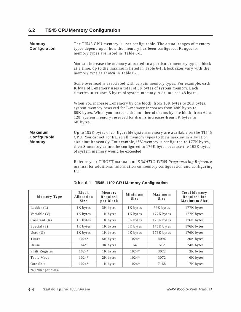
Starting Up the TI555 System6-4 TI545/TI555 System Manual
6.2 TI545 CPU Memory Configuration
The TI545 CPU memory is user configurable. The actual ranges of memorytypes depend upon how the memory has been configured. Ranges formemory types are listed in Table 6-1.
You can increase the memory allocated to a particular memory type, a blockat a time, up to the maximum listed in Table 6-1. Block sizes vary with thememory type as shown in Table 6-1.
Some overhead is associated with certain memory types. For example, eachK byte of L-memory uses a total of 3K bytes of system memory. Eachtimer/counter uses 5 bytes of system memory. A drum uses 48 bytes.
When you increase L-memory by one block, from 16K bytes to 20K bytes,system memory reserved for L-memory increases from 48K bytes to60K bytes. When you increase the number of drums by one block, from 64 to128, system memory reserved for drums increases from 3K bytes to6K bytes.
Up to 192K bytes of configurable system memory are available on the TI545CPU. You cannot configure all memory types to their maximum allocationsize simultaneously. For example, if V-memory is configured to 177K bytes,then S memory cannot be configured to 176K bytes because the 192K bytesof system memory would be exceeded.
Refer to your TISOFT manual and SIMATIC TI505 Programming Referencemanual for additional information on memory configuration and configuringI/O.
Table 6-1 TI545-1102 CPU Memory Configuration
Memory TypeBlock
AllocationSize
MemoryRequiredper Block
MinimumSize
MaximumSize
Total MemoryRequired for
Maximum Size
Ladder (L) 1K bytes 3K bytes 1K bytes 59K bytes 177K bytes
Variable (V) 1K bytes 1K bytes 1K bytes 177K bytes 177K bytes
Constant (K) 1K bytes 1K bytes 0K bytes 176K bytes 176K bytes
Special (S) 1K bytes 1K bytes 0K bytes 176K bytes 176K bytes
User (U) 1K bytes 1K bytes 0K bytes 176K bytes 176K bytes
Timer 1024* 5K bytes 1024* 4096 20K bytes
Drum 64* 3K bytes 64 512 24K bytes
Shift Register 1024* 1K bytes 1024* 3072 3K bytes
Table Move 1024* 2K bytes 1024* 3072 6K bytes
One Shot 1024* 1K bytes 1024* 7168 7K bytes
*Number per block.
MemoryConfiguration
MaximumConfigurableMemory

Starting Up the TI555 System 6-5TI545/TI555 System Manual
6.3 TI555 CPU Memory Configuration
The TI555 CPU memory is user configurable. The actual ranges of memorytypes for each model of the CPU depend upon how the memory has beenconfigured. Ranges for memory types are listed in Table 6-2.
You can increase the memory allocated to a particular memory type, a blockat a time, up to the maximum listed in Table 6-2. Block sizes vary with thememory type as shown in Table 6-2.
Some overhead is associated with certain memory types. For example, eachK-byte of L-memory uses a total of 3K bytes of system memory. Eachtimer/counter uses 5 bytes of system memory. A drum uses 48 bytes. Whenyou increase L-memory by one block, from 16K bytes to 20K bytes, systemmemory reserved for L-memory increases from 48K bytes to 60K bytes.When you increase the number of drums by one block, from 64 to 128,system memory reserved for drums increases from 3K bytes to 6K bytes.
Up to 384K bytes of system memory are available on the PPX:555–1101CPU, and up to 1920K bytes on the PPX:555–1102 CPU. You cannotconfigure all memory types to their maximum allocation sizesimultaneously. For example, (for the TI555–1101) if you configureV-memory to 369K bytes, then you cannot configure S-memory to 368Kbytes because the 384K bytes of system memory would be exceeded.
Refer to your TISOFT manual and SIMATIC TI505 Programming Referencemanual for additional information on memory configuration.
Table 6-2 TI555-1101/1102 CPU Memory Configuration
Memory TypeBlock
AllocationSize
MemoryRequiredper Block
MinimumSize
MaximumSize
–1101 –1102
Total MemoryRequired for
Maximum Size–1101 –1102
Ladder (L) 1K bytes 3K bytes 1K bytes 123Kbytes 635Kbytes 369Kbytes 1905Kbytes
Variable (V) 1K bytes 1K bytes 1K bytes 369Kbytes 1905Kbytes 369Kbytes 1905Kbytes
Constant (K) 1K bytes 1K bytes 0K bytes 368Kbytes 1904Kbytes 368Kbytes 1904Kbytes
Special (S) 1K bytes 1K bytes 0K bytes 368Kbytes 1904Kbytes 368Kbytes 1904Kbytes
User (U) 1K bytes 1K bytes 0K bytes 368Kbytes 1904Kbytes 368Kbytes 1904Kbytes
Timer 1024* 5K bytes 1024* 20480 20480 100Kbytes 100Kbytes
Drum 64* 3K bytes 64* 2304 2304 108Kbytes 108Kbytes
Shift Register 1024* 1K bytes 1024* 16384 16384 16Kbytes 16Kbytes
Table Move 1024* 2K bytes 1024* 14336 14336 28Kbytes 28Kbytes
One Shot 1024* 1K bytes 1024* 32768 32768 32Kbytes 32Kbytes
*Number per block.
MemoryConfiguration
MaximumConfigurableMemory

Troubleshooting 7-1TI545/TI555 System Manual
Chapter 7
Troubleshooting
7.1 Troubleshooting by Using Auxiliary Functions 7-2. . . . . . . . . . . . . . . . . . . . . . . . . . . . . . . . . . . . . Overview 7-2. . . . . . . . . . . . . . . . . . . . . . . . . . . . . . . . . . . . . . . . . . . . . . . . . . . . . . . . . . . . . . . . . . . . . . . Power-up Restart, Partial Restart, and Complete Restart 7-2. . . . . . . . . . . . . . . . . . . . . . . . . . Compare PLC to Disk 7-4. . . . . . . . . . . . . . . . . . . . . . . . . . . . . . . . . . . . . . . . . . . . . . . . . . . . . . . . . . . Run PLC Diagnostics 7-4. . . . . . . . . . . . . . . . . . . . . . . . . . . . . . . . . . . . . . . . . . . . . . . . . . . . . . . . . . . . Display Failed I/O 7-4. . . . . . . . . . . . . . . . . . . . . . . . . . . . . . . . . . . . . . . . . . . . . . . . . . . . . . . . . . . . . . . Show PLC Diagnostic Cell 7-4. . . . . . . . . . . . . . . . . . . . . . . . . . . . . . . . . . . . . . . . . . . . . . . . . . . . . . .
7.2 Troubleshooting by Reading LEDs 7-6. . . . . . . . . . . . . . . . . . . . . . . . . . . . . . . . . . . . . . . . . . . . . . . .
7.3 Troubleshooting Controller Fatal Errors 7-7. . . . . . . . . . . . . . . . . . . . . . . . . . . . . . . . . . . . . . . . . . . . CPU Fatal Error Indications 7-7. . . . . . . . . . . . . . . . . . . . . . . . . . . . . . . . . . . . . . . . . . . . . . . . . . . . . . . Causes of CPU Fatal Errors 7-7. . . . . . . . . . . . . . . . . . . . . . . . . . . . . . . . . . . . . . . . . . . . . . . . . . . . . . . Controller Responses to Fatal Errors 7-7. . . . . . . . . . . . . . . . . . . . . . . . . . . . . . . . . . . . . . . . . . . . . . Steps to Clear Fatal Errors 7-8. . . . . . . . . . . . . . . . . . . . . . . . . . . . . . . . . . . . . . . . . . . . . . . . . . . . . . . Calling for Assistance 7-8. . . . . . . . . . . . . . . . . . . . . . . . . . . . . . . . . . . . . . . . . . . . . . . . . . . . . . . . . . .
7.4 Troubleshooting Controller Non-Fatal Errors 7-9. . . . . . . . . . . . . . . . . . . . . . . . . . . . . . . . . . . . . . .
7.5 Troubleshooting by Using Status Words 7-10. . . . . . . . . . . . . . . . . . . . . . . . . . . . . . . . . . . . . . . . . . .
7.6 Troubleshooting EEPROMs or EPROMs 7-11. . . . . . . . . . . . . . . . . . . . . . . . . . . . . . . . . . . . . . . . . . . . .
7.7 Troubleshooting the Power Supply 7-12. . . . . . . . . . . . . . . . . . . . . . . . . . . . . . . . . . . . . . . . . . . . . . .
7.8 Checking RS-485 (Twisted Pair) Cable Installation 7-14. . . . . . . . . . . . . . . . . . . . . . . . . . . . . . . . . Using Digital or Analog Meter 7-14. . . . . . . . . . . . . . . . . . . . . . . . . . . . . . . . . . . . . . . . . . . . . . . . . . . . Resistance Below Minimum 7-15. . . . . . . . . . . . . . . . . . . . . . . . . . . . . . . . . . . . . . . . . . . . . . . . . . . . . . Resistance Above Maximum 7-15. . . . . . . . . . . . . . . . . . . . . . . . . . . . . . . . . . . . . . . . . . . . . . . . . . . .
7.9 Recommended Spare Parts List 7-16. . . . . . . . . . . . . . . . . . . . . . . . . . . . . . . . . . . . . . . . . . . . . . . . . .

Troubleshooting7-2 TI545/TI555 System Manual
7.1 Troubleshooting by Using Auxiliary Functions
The TI545/TI555 CPU has self-checking and diagnostic capabilities that canbe used for troubleshooting purposes. The diagnostics and self-checks areaccessible through the Auxiliary Function menu on your programmingdevice.
When you display the Auxiliary Function menu, the following functions areavailable for resetting the CPU, initiating diagnostics or displayingdiagnostic information:
• Power-up restart — AUX 10.
• Partial restart — AUX 11.
• Complete restart — AUX 12.
• Compare PLC to Disk — AUX 17.
• Run PLC diagnostics — AUX 20.
• Display failed I/O — AUX 25.
• Show PLC diagnostic cell — AUX 29.
AUX Function 10 (power-up restart), AUX Function 11 (partial restart), andAUX Function 12 (complete restart) are restart/clear functions. SeeTable 7-1 for AUX Function 10, 11, and 12 restart states.
Overview
Power-up Restart,Partial Restart, andComplete Restart

Troubleshooting 7-3TI545/TI555 System Manual
Table 7-1 Effects of Using AUX Functions 10, 11, and 12
Power-up Restart Partial Restart Complete Restart
AUX 10 AUX 11 AUX 12
Battery Battery Battery
System Characteristic ON OFF ON OFF ON OFF
Controller Mode (RUN,PGM HOLD, RAM,ROM)
No change Program** No change* No change* No change* No change*
Loop Processing Mode No change Program/LOCK** No change* No change* No change* No change*
Loop Mode No change N/A No change No change Manual Manual
Discrete I/O (X’s and Y’s) Cleared Cleared Cleared Cleared Cleared Cleared
Word I/O (WX’s and WY’s) No change Cleared No change No change Cleared Cleared
Non-Retentive Control Relays Cleared Cleared Cleared Cleared Cleared Cleared
Retentive Control Relays No change Cleared No change No change Cleared Cleared
Forced Elements No change Cleared No change No change No change No change
TMR/CTR/Drum Presets No change Cleared No change No change Downloaded Downloaded
L, V, K, S, U Memory No change Cleared No change No change No change No change
Memory Configuration No change Default value No change No change No change No change
I/O Configuration No change Cleared No change No change No change No change
Scan Time No change Variable No change No change No change No change
Time of Day No change No change No change No change No change No change
Task Codes/Scan No change 2 No change No change No change No change
Watchdog Value No change 1 sec No change No change No change No change
Port Lockout No change Unlocked No change No change No change No change
Fatal Error No change Cleared Cleared Cleared Cleared Cleared
* If fatal error was present, then Program Mode** If programmed EEPROM (EPROM) is present, then Run Mode using program in EEPROM (EPROM)

Troubleshooting7-4 TI545/TI555 System Manual
Troubleshooting by Using Auxiliary Functions (continued)
AUX Function 17 (Compare PLC to Disk) compares program disk andcontroller data. It allows you to save and load your VERIFY options to andfrom the disk or directory.
AUX Function 20 (run PLC diagnostics) initiates the CPU self-checks. TheCPU must be in PROGRAM mode in order to execute self-tests. The CPUexecutes the equivalent of an AUX Function 20 at every power up. If anyarea fails, a message detailing the failure is displayed. AUX Function 20makes the following tests.
• Valid RAM locations are verified.
• Pre-coded ROM checksum values are checked.
• The hardware force function is checked.
• Internal timer operation is verified.
AUX Function 25 (display failed I/O) displays the locations of any failed I/Omodules which are capable of diagnosing and indicating failure. Somemodules, such as word and analog modules, report that they have failed ifthe user-supplied voltage is not correct.
AUX Function 25 also displays I/O mismatch(es), indicating that one ormore installed module(s) do not agree with the I/O configuration. Verify thatthe configuration data for listed modules is correct before considering thatthe module may actually be malfunctioning.
AUX Function 29 checks the operational status of the CPU and displays theresults. The display provides the information illustrated in Figure 7-1. Fielddescriptions are listed below.
• Scan = scan time reported by AUX Function 29; it is the highest scantime recorded since the last CPU reset, PROGRAM–RUN modetransition, or user peak resets. Status Word 10 (STW10) contains acontinuously updated report of the scan time.
• Key = always unlocked; the CPU does not have a key.
• Mode = Run, Program, or Hold; shows the CPU operating mode.
• SF/Loop Mode = Run indicates the system is running loops, analogalarms, and SF programs in the SF/Loop Mode.
Compare PLCto Disk
Run PLCDiagnostics
Display Failed I/O
Show PLCDiagnostic Cell
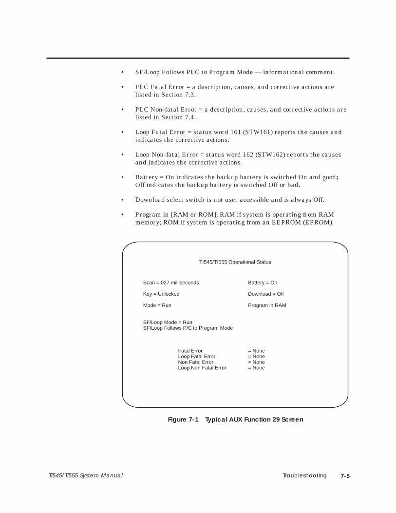
Troubleshooting 7-5TI545/TI555 System Manual
• SF/Loop Follows PLC to Program Mode — informational comment.
• PLC Fatal Error = a description, causes, and corrective actions arelisted in Section 7.3.
• PLC Non-fatal Error = a description, causes, and corrective actions arelisted in Section 7.4.
• Loop Fatal Error = status word 161 (STW161) reports the causes andindicates the corrective actions.
• Loop Non-fatal Error = status word 162 (STW162) reports the causesand indicates the corrective actions.
• Battery = On indicates the backup battery is switched On and good;Off indicates the backup battery is switched Off or bad.
• Download select switch is not user accessible and is always Off.
• Program in [RAM or ROM]; RAM if system is operating from RAMmemory; ROM if system is operating from an EEPROM (EPROM).
TI545/TI555 Operational Status
Scan = 027 milliseconds Battery = On
Key = Unlocked Download = Off
Mode = Run Program in RAM
SF/Loop Mode = RunSF/Loop Follows P/C to Program Mode
Fatal Error = NoneLoop Fatal Error = NoneNon Fatal Error = NoneLoop Non Fatal Error = None
Figure 7-1 Typical AUX Function 29 Screen
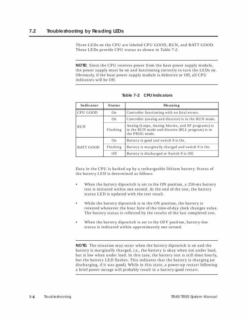
Troubleshooting7-6 TI545/TI555 System Manual
7.2 Troubleshooting by Reading LEDs
Three LEDs on the CPU are labeled CPU GOOD, RUN, and BATT GOOD.These LEDs provide CPU status as shown in Table 7-2.
NOTE: Since the CPU receives power from the base power supply module,the power supply must be on and functioning correctly to turn the LEDs on.Obviously, if the base power supply module is defective or Off, all CPUindicators will be Off.
Table 7-2 CPU Indicators
Indicator Status Meaning
CPU GOOD On Controller functioning with no fatal errors.
On Controller (analog and discrete) is in the RUN mode.
RUNFlashing
Analog (Loops, Analog Alarms, and SF programs) isin the RUN mode and discrete (RLL program) is inthe PROG mode.
On Battery is good and switch 9 is On.
BATT GOOD Flashing Battery is marginally charged and switch 9 is On.BATT GOOD
Off Battery is discharged or Switch 9 is Off.
Data in the CPU is backed up by a rechargeable lithium battery. Status ofthe battery LED is determined as follows:
• When the battery dipswitch is set to the ON position, a 250-ms batterytest is initiated within one second. At the end of the test, the batterystatus LED is updated with the test result.
• While the battery dipswitch is in the ON position, the battery isretested whenever the hour byte of the time-of-day clock changes value.The battery status is reflected by the results of the last completed test.
• When the battery dipswitch is set to the OFF position, battery-lowstatus is indicated within approximately one second.
NOTE: The situation may occur when the battery dipswitch is on and thebattery is marginally charged, i.e., the battery is okay when not under load,but is low when under load. In this case, the battery test is still done hourly,but the battery LED flashes. This indicates that the battery is charging (ordischarging, if it was good). While in this state, a power-up restart followinga brief power outage will probably result in a battery-good restart.
Troubleshooting 7-7TI545/TI555 System Manual
7.3 Troubleshooting Controller Fatal Errors
A fatal error is indicated when both the following conditions are present.
• CPU GOOD LED is not lighted.
• The DC POWER GOOD LED on the power supply is on.
The CPU enters a fatal error condition and ceases operation if one of theproblems listed below occurs. AUX Function 20 or 29 displays the problemthat caused the CPU to enter the fatal error condition.
• ROM diagnostic failure — the operating system EPROMs are found tobe invalid.
• Watchdog time-out — the microprocessor does not reset a watchdogcircuit periodically.
• Illegal operation code — the microprocessor receives an illegalinstruction.
• Diagnostic test failure — the CPU fails a diagnostic test.
• Operating system fatal error — the CPU detects a non-recoverableerror during execution.
• Abnormal power loss — the CPU detects DC power failure withoutadvance warning from the power supply.
• Dynamic Program Memory Diagnostics Error — the CPU determines achecksum error in the user program memory (ladder or externalsubroutine)
• Fatal error due to EEPROM (EPROM) — the EEPROM (EPROM) isbad.
When a fatal error occurs, the CPU attempts the following actions.
• The CPU GOOD LED is turned off.
• I/O ports are disabled, discrete outputs are turned off, and wordoutputs are held in their last valid state.
• Communication ports are cleared and re-initialized.
• Pending or queued communication tasks are aborted.
CPU Fatal ErrorIndications
Causes of CPUFatal Errors
ControllerResponses to FatalErrors

Troubleshooting7-8 TI545/TI555 System Manual
Troubleshooting Controller Fatal Errors (continued)
Attempt to clear the fatal error by following the steps listed below. When theCPU GOOD LED turns on, the fatal error has been cleared.
1. Determine the fatal error condition by selecting AUX Function 29 fromthe Auxiliary Function Menu on your programming unit. Record thefatal and non-fatal error(s) listed along with the date, time, controllerserial number and software part number (AUX 15) for later reference.
NOTE: Always execute AUX Function 29 and make a list of the errors beforeattempting to clear them. If you clear errors before listing them, it will beimpossible to determine what errors occurred and difficult to identify theproblem that caused them.
If communication errors occur, ensure that the battery backup is enabledand then cycle power to the controller. If communication errors continue,record No Communication as the fatal error, and go to step 4.
2. Execute AUX Function 11 — CPU partial restart. If this fails to clearthe error, execute AUX Function 12 — CPU complete restart.
3. If the fatal error persists, ensure that the battery backup is enabled,power cycle the CPU, then reattempt step 2 and execute the AUXFunction 10 — CPU power-up restart.
4. If you have been unable to clear the fatal error to this point, you mustre-initialize the CPU. Disable the battery backup (turn off switch 9 ofthe dipswitch) and cycle power to the CPU (or execute AUXFunction 10). This clears the CPU memory.
5. If the CPU GOOD LED comes on, restore the battery backup byturning on switch 9 of the dipswitch. You must now use yourprogramming unit to restore your program.
6. If the CPU GOOD LED does not turn on at this time, your CPU mayhave a hardware failure.
Before calling for assistance, be sure that you have the followinginformation available.
• List of fatal and non-fatal errors
• Model number
• CPU serial number
• CPU software revision (execute AUX Function 15 or check the EPROMlabel)
• Sequence of events leading up to the failure
Steps toClear Fatal Errors
Calling forAssistance

Troubleshooting 7-9TI545/TI555 System Manual
7.4 Troubleshooting Controller Non-Fatal Errors
Definitions of non-fatal errors are listed in this section along with suggestedcourses of action.
• Scan overrun — The CPU scan time is not sufficient to execute the userprogram.
• I/O base failure — A configured base is not connected or has failed.Check the I/O cabling and/or I/O configuration.
• Special function port failure — A communication port on an SF modulehas failed. Check all SF modules.
• I/O module failure — A configured module is not present or is reportingan error. Run AUX 25 or see Appendix C to identify the module.
• I/O table does not agree with modules installed — The configured I/Odoes not match what is installed in the base. Check the I/Oconfiguration and/or run AUX 25.
NOTE: Series 505 I/O modules with date codes before January 1988 cannotbe used with a TI545/TI555 CPU. See Appendix C for details.

Troubleshooting7-10 TI545/TI555 System Manual
7.5 Troubleshooting by Using Status Words
In addition to auxiliary functions, the CPU provides operational informationin the form of 16-bit status words. Status words can be read with yourprogramming device. Status words can also be used within a RLL programthus allowing the system to execute diagnostics during run-time conditions.
Status words supported by the CPU are described in detail in the SIMATICTI505 Programming Reference Manual.
Troubleshooting 7-11TI545/TI555 System Manual
7.6 Troubleshooting EEPROMs or EPROMs
EEPROMs and EPROMs are generally not serviceable and must be replacedif they become defective. Before replacement however, review material inChapter 5, Using an EEPROM or EPROM, and perform the followingchecks.
• Ensure that the EEPROM programming enable strap is installedcorrectly on the jumper pin E18. (See Figure 5-1.)
• Ensure that an EEPROM or EPROM is installed, depending on youruse.
• Ensure that all EEPROM (EPROM) pins are properly seated in thesocket.
Other possible causes for errors include the following.
• The EEPROM may already have been programmed (and not erased).Use the AUX Function 84 to erase program data on the EEPROM.
• The size of your user program (L, K, S, and U memories) that is beingstored may exceed the size of the (E)EPROM (126 or 254K bytes).
NOTE: To help ensure that the user program will be saved, the total usermemory space occupied by the user program must not exceed the size of the(E)EPROM minus 2K bytes (126K or 254K bytes). If the total user memory(not system memory) space occupied by these user programs is greater thanthis value, none of the data is saved and the error message, OPERATIONFAILED , is displayed on the screen when attempting to save the data.

Troubleshooting7-12 TI545/TI555 System Manual
7.7 Troubleshooting the Power Supply
Complete the following steps when troubleshooting the power supply.
1. Ensure that the power budget has not been exceeded and that themodule is properly installed.
2. After making sure the backup battery is on (so the program will not belost), disable all power to the system for at least 90 seconds.
3. Restore system power.
4. If the problem still exists, turn off power to the system.
To minimize risk of shock hazard, always turn off the controllerbefore removing or installing a CPU or I/O module.
Failure to do so could cause death or serious injury and/or damageto equipment.
Ensure that controller power is turned off before removing orinstalling a CPU or I/O module.
5. Remove the power supply module from the base. This step is notrequired for the PPX:505–6663 power supply.
a. Ensure that the jumper in the back of the power supply module isset to the correct line voltage.
b. If the voltage has been set incorrectly, wait at least one minutebefore touching the jumper. Then move the jumper to theappropriate quick-connect pin.
6. Ensure that the wires attached to the terminal screws on the bezel aresecure and that the user-supplied power source is functional.
7. Verify that the fuse (located on the bezel) has not opened. Follow steps8. through 12. to replace the fuse, if necessary, with the appropriatefuse. See Figure 7-2 .
Before you replace a fuse, disable all power to the base .
Failure to do so could cause death or serious injury and/or damageto equipment.
Disable all power to the base before replacing a fuse.
WARNING!
WARNING!

Troubleshooting 7-13TI545/TI555 System Manual
8. Turn off power to the power supply module.
9. Turn the fuse cap counterclockwise a half-turn with a standardscrewdriver.
10. Pull the fuse cap out of the fuse socket.
11. Remove and replace fuse.
NOTE: PPX:505–6660A requires a 3 A, 250 V, slow-blow fuse. PPX:505–6663requires an 8 A, 250 V, normal-blow fuse.
12. Place the fuse cap in socket and turn it clockwise with a standardscrewdriver.
Fuse Cap
Front Bezel
Fuse
Figure 7-2 Replacing PPX:505–6660 Power Supply Fuse
13. Re-install the power supply and apply power to the system.
14. If the power supply continues to malfunction, replace it.
Follow procedures established at your site for processing defectiveequipment. If necessary, contact your distributor or sales office in theUnited States or call Siemens Industrial Automation, Inc., at (800)964–4114 for assistance in contacting your distributor or sales office.
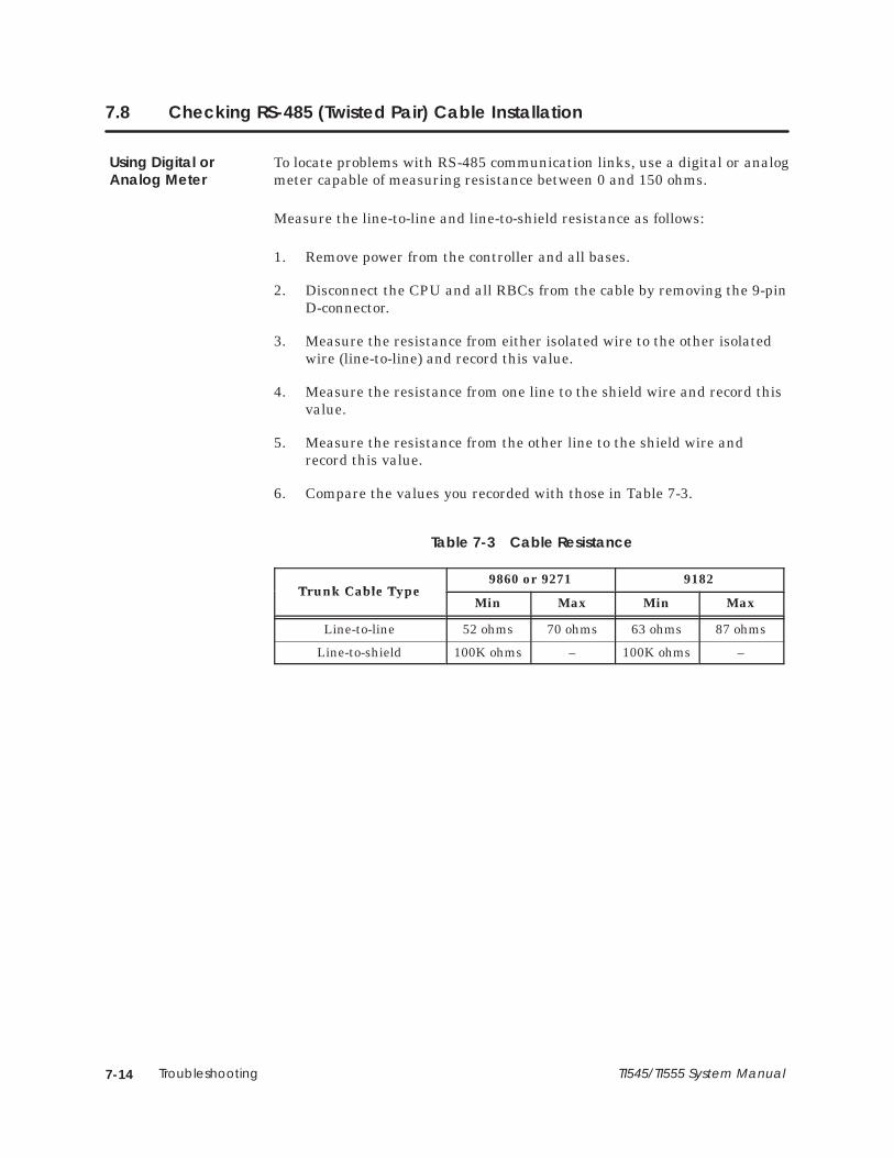
Troubleshooting7-14 TI545/TI555 System Manual
7.8 Checking RS-485 (Twisted Pair) Cable Installation
To locate problems with RS-485 communication links, use a digital or analogmeter capable of measuring resistance between 0 and 150 ohms.
Measure the line-to-line and line-to-shield resistance as follows:
1. Remove power from the controller and all bases.
2. Disconnect the CPU and all RBCs from the cable by removing the 9-pinD-connector.
3. Measure the resistance from either isolated wire to the other isolatedwire (line-to-line) and record this value.
4. Measure the resistance from one line to the shield wire and record thisvalue.
5. Measure the resistance from the other line to the shield wire andrecord this value.
6. Compare the values you recorded with those in Table 7-3.
Table 7-3 Cable Resistance
Trunk Cable Type9860 or 9271 9182
Trunk Cable TypeMin Max Min Max
Line-to-line 52 ohms 70 ohms 63 ohms 87 ohms
Line-to-shield 100K ohms – 100K ohms –
Using Digital orAnalog Meter

Troubleshooting 7-15TI545/TI555 System Manual
Checking RS-485 (Twisted Pair) Cable Installation (continued)
Line-to-line resistance that is below the minimum specified in Table 7-3may be caused by the following:
• Incorrect termination resistors are installed.
• More than two termination resistors are installed.
• There is a short in the cable.
Line-to-shield resistance that is below the minimum specified in Table 7-3may be caused by the following:
• One of the 9-pin connectors is connected to an RBC or CPU.
• Cable line wires are shorted to the shield.
Line-to-line resistance that is above the maximum specified in Table 7-3may be caused by the following:
• Incorrect termination resistors are installed.
• Fewer than two termination resistors are installed.
• The cable is open between the point of measurement and one or both ofthe termination resistors.
Resistance BelowMinimum
Resistance AboveMaximum

Troubleshooting7-16 TI545/TI555 System Manual
7.9 Recommended Spare Parts List
Siemens Industrial Automation, Inc., recommends that you maintain a 10%surplus of your system’s I/O modules as available spare parts. Dependingupon the number of CPUs that you have installed, you may wish to stock anextra controller as well. Additional spare parts, depending upon your siteconfiguration, include the following:
• PPX:505–6504, 4 I/O slots base.
• PPX:505–6508, 8 I/O slots base.
• PPX:505–6511, 11 I/O slots base.
• PPX:505–6516, 16 I/O slots base (19-inch rack compatible).
• PPX:505–6660A or PPX:505–6663, Power Supply Module.
• 3.0A/250 V, slow-blow fuse (3AG) for PPX:505–6660A,PPX:2587679–8015, Qty 5.
• 8.0A/250 V, normal-blow fuse (3AG) for PPX:505–6663,PPX:2587679–8018, Qty 5.
Order the following spare parts as needed from your supplier or SiemensIndustrial Automation:
• EEPROM, 128K x 8, PPX:2587681–8022EEPROM, 256K x 8, PPX:2587681–8030.
• EPROM, 128K x 8, PPX:2587681–8023EPROM, 256K x 8, PPX:2587681–8031.
• RS-232-C/RS-423 9-to-9 Pin Programming Cable, Part #2601094–8001.

System Specifications A-1TI545/TI555 System Manual
Appendix A
System Specifications
A.1 Series 505 System Specifications A-2. . . . . . . . . . . . . . . . . . . . . . . . . . . . . . . . . . . . . . . . . . . . . . . . .

System SpecificationsA-2 TI545/TI555 System Manual
A.1 Series 505 System Specifications
Table A-1 Environmental Specifications
Models
PPX:545–1102 ControllerPPX:555–1101 ControllerPPX:555–1102 ControllerPPX:505–6851 Remote Base ControllerPPX:505–6660A Power SupplyPPX:505–6663 Power Supply
Storage Temperature –40° to 70°C; –40° to 158°F
Operating Temperature 0° to 60°C; 32° to 140°F
Relative Humidity 5% to 95% noncondensing
Vibration Sinusoidal:
Random:
IEC 68-2-6, Test Fc;0.15 mm peak-to-peak, 10–57 Hz; 1.0 g, 57–150 Hz
NAVMAT P–9492 or IEC 68–2–34,Test Fdc with 0.04 g2 /Hz, 80–350 Hz, and 3 dB/octave rolloff, 80–20 Hz and 350–2000 Hz at 10 min/axis
Impact Shock IEC, 68–2–27, Test Ea; Half sine, 15 g 11 ms
Pollution Degree 2, IEC664, 684A
Electric Noise ImmunityConducted noise:
Radiated noise:
Electrostatic discharge:
IEC 801, Part 4, Level 3MIL-STD-461B, Part 4; CS01, CS02, CS06IEC 255–4, Appendix CEEC 4517/79 Com(78) 766 Final, Part 4IEEE 472, 2.5 kV
IEC 801 Part 3, Level 3MIL-STD-461B, Part 4; RS01, RS02
IEC 801, Part 2, Level 4 (15 kV)
System Isolation 1500 Vrms (user-side to controller-side)
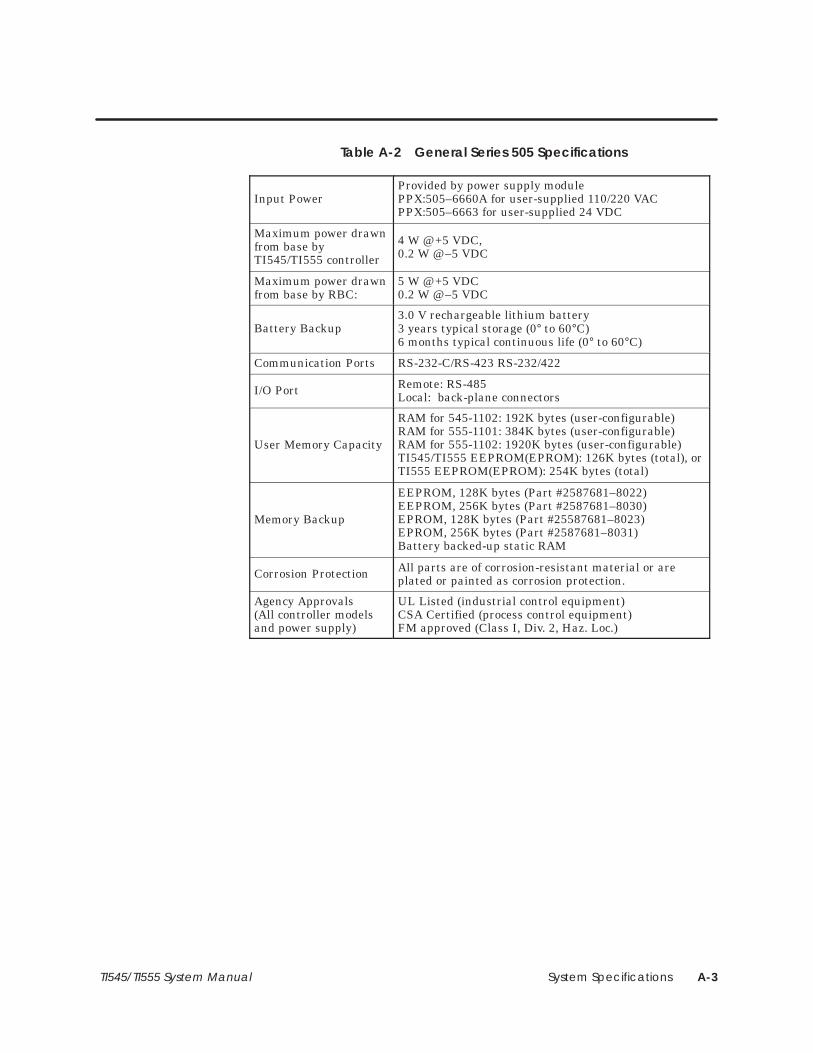
System Specifications A-3TI545/TI555 System Manual
Table A-2 General Series 505 Specifications
Input PowerProvided by power supply modulePPX:505–6660A for user-supplied 110/220 VACPPX:505–6663 for user-supplied 24 VDC
Maximum power drawnfrom base byTI545/TI555 controller
4 W @ +5 VDC, 0.2 W @ –5 VDC
Maximum power drawnfrom base by RBC:
5 W @ +5 VDC 0.2 W @ –5 VDC
Battery Backup3.0 V rechargeable lithium battery 3 years typical storage (0° to 60°C)6 months typical continuous life (0° to 60°C)
Communication Ports RS-232-C/RS-423 RS-232/422
I/O Port Remote: RS-485Local: back-plane connectors
User Memory Capacity
RAM for 545-1102: 192K bytes (user-configurable)RAM for 555-1101: 384K bytes (user-configurable)RAM for 555-1102: 1920K bytes (user-configurable)TI545/TI555 EEPROM(EPROM): 126K bytes (total), orTI555 EEPROM(EPROM): 254K bytes (total)
Memory Backup
EEPROM, 128K bytes (Part #2587681–8022)EEPROM, 256K bytes (Part #2587681–8030)EPROM, 128K bytes (Part #25587681–8023)EPROM, 256K bytes (Part #2587681–8031)Battery backed-up static RAM
Corrosion Protection All parts are of corrosion-resistant material or areplated or painted as corrosion protection.
Agency Approvals(All controller modelsand power supply)
UL Listed (industrial control equipment)CSA Certified (process control equipment)FM approved (Class I, Div. 2, Haz. Loc.)

System SpecificationsA-4 TI545/TI555 System Manual
Series 505 System Specifications (continued)
Table A-3 Power Supply Electrical Specifications
Input Voltage Select, PPX:505–6660 110/220 VAC (User-selectable)
Voltage Range PPX:505–6660A
85–132 VAC (110), or170–264 VAC (220)
PPX:505–6663 20–30 VDC (24)
Frequency PPX:505–6660A 47–63 Hz
Input CurrentPeak Inrush – PPX:505–6660APeak Inrush – PPX:505–6663
Steady state – PPX:505–6660ASteady state – PPX:505–6663
Volt-Amp rating – PPX:505–6660AWattage rating – PPX:505–6663
50 A maximum20 A maximum
2 A rms maximum8 A zero to peak5 A DC maximum
200 V-A100 W maximum
Output 55 W at +5 VDC3.75 W at –5 VDC
FusePPX:505–6660APPX:505–6663
3.0A/250 V, slow-blow, 3 AG8.0A/250 V, normal-blow, 3 AG
In addition, the system complies with applicable requirements of VerbandDeutscher Elektrotechniker (VDE) 0160: Electrical Equipment, except 220VAC Input Modules (No. PPX:505-44XX).
Series 505 products have been developed with consideration of the draftstandard for programmable controllers as described in the proposedstandard of the International Electrotechnical Commission Committee(IEC-65A/WG6, Part 2).
Information concerning product reliability and compliance to the IEC orother standards can be provided upon request. Contact Siemens IndustrialAutomation at the following address.
Siemens Industrial Automation Incorporated3000 Bill Garland RoadP.O. Box 1255,Johnson City, TN. 37605-1255

Module Power Consumption B-1T545/TI555 System Manual
Appendix B
Module Power Consumption
B.1 Series 505 Modules B-2. . . . . . . . . . . . . . . . . . . . . . . . . . . . . . . . . . . . . . . . . . . . . . . . . . . . . . . . . . . . .
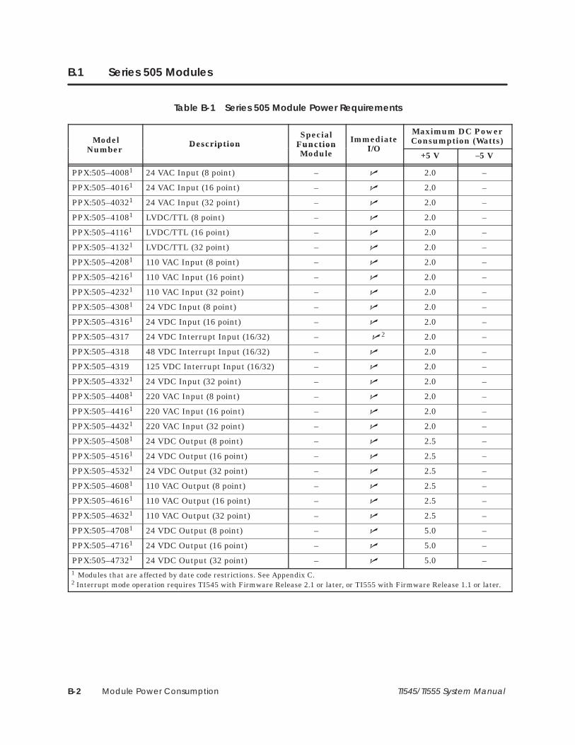
Module Power ConsumptionB-2 TI545/TI555 System Manual
B.1 Series 505 Modules
Table B-1 Series 505 Module Power Requirements
Modelumber
DescriptionSpecial
FunctionModule
ImmediateI/
Maximum DC PowerConsumption (Watts)
NumberDescription Function
Module I/O+5 V –5 V
PPX:505–40081 24 VAC Input (8 point) – � 2.0 –
PPX:505–40161 24 VAC Input (16 point) – � 2.0 –
PPX:505–40321 24 VAC Input (32 point) – � 2.0 –
PPX:505–41081 LVDC/TTL (8 point) – � 2.0 –
PPX:505–41161 LVDC/TTL (16 point) – � 2.0 –
PPX:505–41321 LVDC/TTL (32 point) – � 2.0 –
PPX:505–42081 110 VAC Input (8 point) – � 2.0 –
PPX:505–42161 110 VAC Input (16 point) – � 2.0 –
PPX:505–42321 110 VAC Input (32 point) – � 2.0 –
PPX:505–43081 24 VDC Input (8 point) – � 2.0 –
PPX:505–43161 24 VDC Input (16 point) – � 2.0 –
PPX:505–4317 24 VDC Interrupt Input (16/32) – �2 2.0 –
PPX:505–4318 48 VDC Interrupt Input (16/32) – � 2.0 –
PPX:505–4319 125 VDC Interrupt Input (16/32) – � 2.0 –
PPX:505–43321 24 VDC Input (32 point) – � 2.0 –
PPX:505–44081 220 VAC Input (8 point) – � 2.0 –
PPX:505–44161 220 VAC Input (16 point) – � 2.0 –
PPX:505–44321 220 VAC Input (32 point) – � 2.0 –
PPX:505–45081 24 VDC Output (8 point) – � 2.5 –
PPX:505–45161 24 VDC Output (16 point) – � 2.5 –
PPX:505–45321 24 VDC Output (32 point) – � 2.5 –
PPX:505–46081 110 VAC Output (8 point) – � 2.5 –
PPX:505–46161 110 VAC Output (16 point) – � 2.5 –
PPX:505–46321 110 VAC Output (32 point) – � 2.5 –
PPX:505–47081 24 VDC Output (8 point) – � 5.0 –
PPX:505–47161 24 VDC Output (16 point) – � 5.0 –
PPX:505–47321 24 VDC Output (32 point) – � 5.0 –1 Modules that are affected by date code restrictions. See Appendix C.2 Interrupt mode operation requires TI545 with Firmware Release 2.1 or later, or TI555 with Firmware Release 1.1 or later.
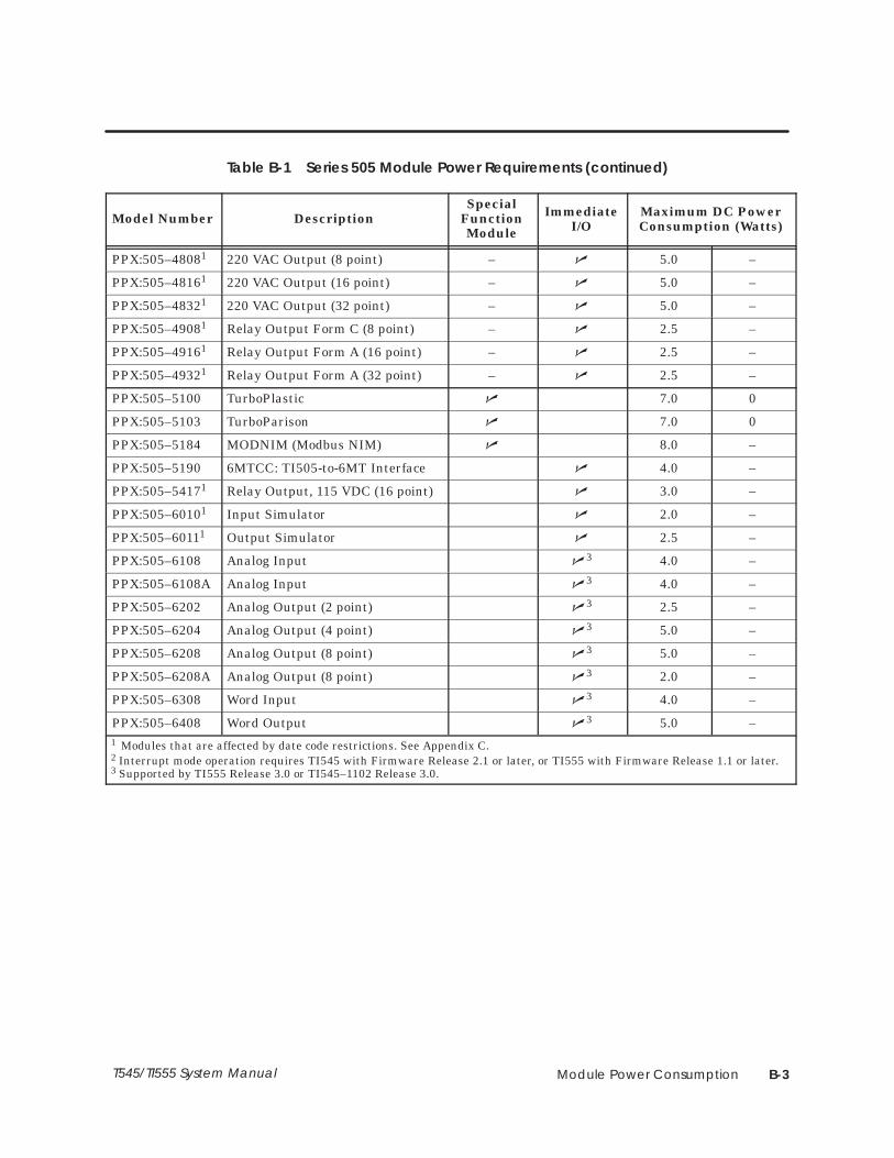
Module Power Consumption B-3T545/TI555 System Manual
Table B-1 Series 505 Module Power Requirements (continued)
Model Number DescriptionSpecial
FunctionModule
ImmediateI/O
Maximum DC PowerConsumption (Watts)
PPX:505–48081 220 VAC Output (8 point) – � 5.0 –
PPX:505–48161 220 VAC Output (16 point) – � 5.0 –
PPX:505–48321 220 VAC Output (32 point) – � 5.0 –
PPX:505–49081 Relay Output Form C (8 point) – � 2.5 –
PPX:505–49161 Relay Output Form A (16 point) – � 2.5 –
PPX:505–49321 Relay Output Form A (32 point) – � 2.5 –
PPX:505–5100 TurboPlastic � 7.0 0
PPX:505–5103 TurboParison � 7.0 0
PPX:505–5184 MODNIM (Modbus NIM) � 8.0 –
PPX:505–5190 6MTCC: TI505-to-6MT Interface � 4.0 –
PPX:505–54171 Relay Output, 115 VDC (16 point) � 3.0 –
PPX:505–60101 Input Simulator � 2.0 –
PPX:505–60111 Output Simulator � 2.5 –
PPX:505–6108 Analog Input �3 4.0 –
PPX:505–6108A Analog Input �3 4.0 –
PPX:505–6202 Analog Output (2 point) �3 2.5 –
PPX:505–6204 Analog Output (4 point) �3 5.0 –
PPX:505–6208 Analog Output (8 point) �3 5.0 –
PPX:505–6208A Analog Output (8 point) �3 2.0 –
PPX:505–6308 Word Input �3 4.0 –
PPX:505–6408 Word Output �3 5.0 –
1 Modules that are affected by date code restrictions. See Appendix C.2 Interrupt mode operation requires TI545 with Firmware Release 2.1 or later, or TI555 with Firmware Release 1.1 or later.3 Supported by TI555 Release 3.0 or TI545–1102 Release 3.0.

Module Power ConsumptionB-4 TI545/TI555 System Manual
Series 505 Modules (continued)
Table B-1 Series 505 Module Power Requirements (continued)
Model Number DescriptionSpecial
FunctionModule
ImmediateI/
Maximum DC PowerConsumption (Watts)Model Number Description Function
Module I/O+5 V –5 V
PPX:505–6851A Remote Base Controller (RBC) 5.0 0.200
PPX:505–6860 RF to RS-485 Converter 4 4
PPX:505–7002 High Speed Counter & Encoder �3 2.0 –
PPX:505–7003 High Speed Counter Encoder �3 2.0 –
PPX:505–7012 8 In/4 Out Analog �2 3.0 0.030
PPX:505–7016 Bipolar 8 In/4 Out Analog � 3.0 0.030
PPX:505–7028 Thermocouple Input � 2.2 0.01
PPX:505–7038 RTD Input � 2.2 0
PPX:505–7101 BASIC Module � 6.0 0.125
PPX:505–7190 7MT Channel Controller 4.0 –
PPX:505–7201 FIM (Field Inteface Module) 2.5 –
PPX:505–7339 NIM (Network Interface Module) � 8.0 –
PPX:505–7340 Dual Media NIM � 8.0 –
PPX:505–7354 Peerlink � 8.0 –
PPX:505–ATM–0220–0440, –4120
386/ATM Coprocessor Module(IBM AT-Compatible Coprocessor) � 11.0 0.2
PPX:545–1102PPX:555–1101PPX:555–1102
Programmable Logic Controller 4.0 0.200
Notes: 1 Modules that are affected by date code restrictions. See Appendix C.
2 Only inputs should be used for immediate I/O when using Release 1.1.x of TI555. No restriction with Release 3.0. 3 Supported by TI555 Release 3.0 or TI545–1102 Release 3.0.
4 Refer to TI555 Release 3.0 Notes.
For any module not listed here, see the manual for that module.

TI545/TI555 Controller and I/O Compatibility C-1TI545/TI555 System Manual
Appendix C
TI545/TI555 CPU and I/O Compatibility
C.1 I/O Module Compatibility C-2. . . . . . . . . . . . . . . . . . . . . . . . . . . . . . . . . . . . . . . . . . . . . . . . . . . . . . . I/O Modules not Compatible with TI545/TI555 CPUs C-2. . . . . . . . . . . . . . . . . . . . . . . . . . . . . . . Determining the Compatibility of a Module C-3. . . . . . . . . . . . . . . . . . . . . . . . . . . . . . . . . . . . . . Series 505 High Speed Counter C-3. . . . . . . . . . . . . . . . . . . . . . . . . . . . . . . . . . . . . . . . . . . . . . . . . .
C.2 Reading the Serial Numbers C-4. . . . . . . . . . . . . . . . . . . . . . . . . . . . . . . . . . . . . . . . . . . . . . . . . . . . . Determining the Manufacturing Date C-4. . . . . . . . . . . . . . . . . . . . . . . . . . . . . . . . . . . . . . . . . . . . Examples C-4. . . . . . . . . . . . . . . . . . . . . . . . . . . . . . . . . . . . . . . . . . . . . . . . . . . . . . . . . . . . . . . . . . . . . . . 86ML8712020175_ C-4. . . . . . . . . . . . . . . . . . . . . . . . . . . . . . . . . . . . . . . . . . . . . . . . . . . . . . . . . . . . . . . 86ML8712020175G C-4. . . . . . . . . . . . . . . . . . . . . . . . . . . . . . . . . . . . . . . . . . . . . . . . . . . . . . . . . . . . . . 86ML8801041324_ C-4. . . . . . . . . . . . . . . . . . . . . . . . . . . . . . . . . . . . . . . . . . . . . . . . . . . . . . . . . . . . . . .
TI545/TI555 Controller and I/O CompatibilityC-2 TI545/TI555 System Manual
C.1 I/O Module Compatibility
Unmodified Series 505 discrete I/O modules manufactured prior toJanuary, 1988 are unable to report module status and, therefore, cannot berecognized by the TI545/TI555 CPU (that is, inputs are not read andoutputs are not written). Series 505 discrete I/O modules manufactured inJanuary, 1988 or later and those manufactured prior to this date that havebeen modified contain the status reporting mechanism and are compatiblewith the TI545/TI555 CPU.
The Series 505 Simulators (PPX:505–6010, 32-Input Simulator andPPX:505–6011, 32-Output Simulator) are also affected by this compatibilityrestriction.
NOTE: Note1 in Table B-1 indentifies all affected modules.
The following modules are fully compatible with the TI545/TI555 CPU,regardless of the manufacturing date.
• All Series 500 I/O and all non-discrete Series 505 I/O, such as analogmodules (except for the High Speed Counter, as described on page C-3)
• Series 505 Word modules (PPX:505–6308, 8-Channel Word Input andPPX:505–6408, 8-Channel Word Output)
I/O Modules notCompatible withTI545/TI555 CPUs

TI545/TI555 Controller and I/O Compatibility C-3TI545/TI555 System Manual
The serial number found on each module contains the manufacturing dateof the module. The fifth through the eighth characters of the serial numberdetermines the manufacturing date; see Figure C-1.
NOTE: Units manufactured prior to January, 1988 that have been modifiedhave the letter G immediately following the serial number.
Before you install Series 505 discrete modules into a TI545/TI555 system,check the serial number of each module to ensure it is compatible with theTI545/TI555 CPU.
High Speed Counter modules (PPX:505-7002) manufactured prior to May1990 will not operate properly in a TI545/TI555 controller’s local baseconfiguration. If a High Speed Counter is placed in a TI545/TI555controller’s local base configuration, the WX inputs will intermittently set toFFs, which could cause improper operation.
NOTE: High Speed Counter modules manufactured prior to May 1990 thathave been modified for TI545/TI555 controller’s local base compatibilityhave the letter A immediately following the serial number.
Before you install Series 505 High Speed Counter modules into aTI545/TI555 local base, check the serial number of each module to ensurethat it is compatible with the TI545/TI555 local base.
Do not use an unmodified Series 505 High Speed Counter modulemanufactured prior to May 1990 in a TI545/TI555 controller’s localbase.In a Series 505 High Speed Counter, WX inputs may change to FFsthat could change the High Speed Counter outputs to an unsafecondition. This could result in death or serious injury and/ordamage to equipment.
Refer to the Safety Considerations Guidelines, part no.2588015-0003 (shipped with each TI545/TI555 controller), for details.Follow Siemens Industrial Automation, Inc.’s recommended safetyinstallation guidelines.
Determining theCompatibility of aModule
Series 505 HighSpeed Counter
WARNING!

TI545/TI555 Controller and I/O CompatibilityC-4 TI545/TI555 System Manual
C.2 Reading the Serial Numbers
The fifth through the eighth characters of the serial number determines themanufacturing date. Figure C-1 shows how to read the serial numbers.
Not present with initial serial number;a G appears here if the Series 505Discrete Module was manufacturedprior to January, 1988 but was modifiedfor TI545/TI555 compatibility.
Serial Number Checksum
Unique Unit Identifier
Month of Manufacture
Last Two Digits of Year of Manufacture
Device Indicator
Family Indicator
FF DD YY MM SSSSS C X
Serial Number
Figure C-1 Serial Number Definition
The following examples demonstrate how to read the serial number on themodules.
This module was manufactured in December (12) of 1987 (87). This unit isnot compatible with the TI545/TI555 controller because it wasmanufactured prior to January, 1988 and the letter G (designating that amodification occurred) does not appear at the end of the serial number.
This module was manufactured in December (12) of 1987 (87). This unit iscompatible with the TI545/TI555 controller because it was manufacturedprior to January, 1988 and the letter G (designating that a modificationoccurred) appears at the end of the serial number.
This module was manufactured in January (01) of 1988 (88). This unit iscompatible with the TI545/TI555 controller because it was manufactured inJanuary, 1988. (The letter G is not required if the module wasmanufactured in January, 1988 or later.)
Determining theManufacturingDate
Examples
86ML8712020175_
86ML8712020175G
86ML8801041324_

Upgrading Existing Series 500 Installations D-1TI545/TI555 System Manual
Appendix D
Upgrading Series 500 Installations
D.1 Series 500 System Installations D-2. . . . . . . . . . . . . . . . . . . . . . . . . . . . . . . . . . . . . . . . . . . . . . . . . . .
D.2 Upgrading a TI520/TI520C/TI530/TI530C/TI530T System D-3. . . . . . . . . . . . . . . . . . . . . . . . . . . . Install RS-485 Twin Axial Cabling D-3. . . . . . . . . . . . . . . . . . . . . . . . . . . . . . . . . . . . . . . . . . . . . . . . . . Check Base to be Upgraded D-4. . . . . . . . . . . . . . . . . . . . . . . . . . . . . . . . . . . . . . . . . . . . . . . . . . . . Upgrading 14-Slot, 12-Slot, 6-Slot Bases D-4. . . . . . . . . . . . . . . . . . . . . . . . . . . . . . . . . . . . . . . . . . . Upgrading 16-Slot and 8-Slot Bases D-4. . . . . . . . . . . . . . . . . . . . . . . . . . . . . . . . . . . . . . . . . . . . . . Finish Upgrade with these Steps D-4. . . . . . . . . . . . . . . . . . . . . . . . . . . . . . . . . . . . . . . . . . . . . . . . . .
D.3 Upgrading an RS-485 Based TI560/TI565/TI560T/TI565P System D-6. . . . . . . . . . . . . . . . . . . . .
D.4 Upgrading an RF Based TI560/TI565/TI560T/TI565P System D-8. . . . . . . . . . . . . . . . . . . . . . . . . .
D.5 Installing a PPX:500–5114A RBC D-10. . . . . . . . . . . . . . . . . . . . . . . . . . . . . . . . . . . . . . . . . . . . . . . . . . Output State Selection D-10. . . . . . . . . . . . . . . . . . . . . . . . . . . . . . . . . . . . . . . . . . . . . . . . . . . . . . . . . . Installing a Series 500 RBC D-11. . . . . . . . . . . . . . . . . . . . . . . . . . . . . . . . . . . . . . . . . . . . . . . . . . . . . . . Setting Baud Rates D-12. . . . . . . . . . . . . . . . . . . . . . . . . . . . . . . . . . . . . . . . . . . . . . . . . . . . . . . . . . . . . . Assigning Base Numbers D-12. . . . . . . . . . . . . . . . . . . . . . . . . . . . . . . . . . . . . . . . . . . . . . . . . . . . . . . . . Series 500 RBC LED Display D-13. . . . . . . . . . . . . . . . . . . . . . . . . . . . . . . . . . . . . . . . . . . . . . . . . . . . . . .
Upgrading Existing Series 500 InstallationsD-2 TI545/TI555 System Manual
D.1 Series 500 System Installations
You can upgrade an existing Series 500 system, by replacing the controllerwith a TI545–1102 or a TI555. The following Series 500 systems can beupgraded:
• SIMATIC TI520 , TI520C , TI530 , TI530C , and TI530T systems.
• SIMATIC TI560 , TI560T , TI565 , and TI565P systems using twinaxial (RS-485) remote I/O channels.
• SIMATIC TI560, TI560T, TI565, and TI565P systems using coaxial(RF) remote I/O channels.
Refer to Section D.2 for information about upgrading an existing TI520,TI520C, TI530, TI530C, or TI530T systems.
Refer to Section D.3 for information about upgrading an existing TI560,TI560T, TI565, or TI565P system with one or more RS-485 remote I/Ochannels.
Refer to Section D.4 for information about upgrading an existing TI560,TI560T, TI565, or TI565P system with one or more coaxial remote I/Ochannels.

Upgrading Existing Series 500 Installations D-3TI545/TI555 System Manual
D.2 Upgrading a TI520/TI520C/TI530/TI530C/TI530T System
To upgrade a TI520, TI520C, TI530, TI530C, or TI530T system to theTI545/TI555 you must install a twin axial (RS-485) remote I/O channel toconnect the Series 500 bases to the TI545/TI555.
You must also convert each of the existing series 500 bases to a series 500remote base by replacing the existing programmable controller (and I/Ochannel controller, if present) or the existing distributed base controllerwith a PPX:500–5114A (RS-485) Remote Base Controller (RBC). If the basecontains a TI520, TI530, or a PPX:500–2103 distributed base controller youmust install an adapter base and modular power supply before you caninstall the RBC in the Series 500 base.
Consider these points as you do the upgrade:
• The Series 500 physical base assembly is composed of one or two logicalbases. A logical base is defined as a contiguous group of eight I/O slots.For example, the 16-slot physical base assembly has two 8-slot logicalbases. Each logical base has a unique base address.
By comparison, the TI545/TI555 remote base assembly addresses up to16 contiguous slots with a single base address.
• To reduce down time for your process, plan to install the new RS-485twin axial cables for the I/O trunkline before upgrading the hardwarefor each I/O base.
• Update time for a special function module is significantly faster whenyou install the module in the local base, versus a remote base. Becausethe TI545/TI555 is installed in a Series 505 local base, Series 500 SFmodules cannot be located in the TI545/TI555 local base. Therefore, ifSF module updates are critical to your application, consider replacingthe Series 500 SF modules with Series 505 SF modules and installingthem in the TI545/TI555 local base.
If all SF modules cannot be installed in the local base, consider placinglow-activity SF modules, such as the ASCII, BASIC, or Dual CommPort (DCP) modules, in a remote base. Place high-activity modules,such as the NIM or Peerlink, in the local base.
To do an upgrade, refer to Figure D-1 and follow the procedure below.
Refer to Chapter 4 “Cabling and Wiring the System,” for information aboutinstalling RS-485 twin axial cabling for the I/O trunk line. To reduce thedown time for your process, install the cabling before installing newhardware in each I/O base.
Install RS-485 TwinAxial Cabling

Upgrading Existing Series 500 InstallationsD-4 TI545/TI555 System Manual
Upgrading a TI520/TI520C/TI530/TI530C/TI530T System (continued)
Determine the number of I/O slots in the base to be upgraded. For somebases, a PPX:500–5840 adapter base must be installed. The 14-slot, 12-slotand 6-slot bases (Upgrade Path A) do not require an adapter base. For a16-slot or 8-slot base (Upgrade Path B), you need to install an adapter base.
Disable all power to bases before installing or removing modules.Failure to do so could cause death or serious injury and/or damageto equipment.
Ensure that all power is disabled before installing or removingmodules.
For 14-slot, 12-slot and 6-slot bases follow these steps (Upgrade Path A):
1. Remove the existing controlling device(s): the controller and IOCC (ifan IOCC is present), or the DBC.
2. If the power supply is in slot B, move it to slot A of the I/O base. Thismakes slot B of the I/O base available for an I/O module. In your I/Oconfiguration, the slot that was previously slot #1 becomes slot #2.
For 16-slot and 8-slot bases follow these steps (Upgrade Path B):
1. Remove the existing controlling device(s): the controller and IOCC (ifan IOCC is present), or the DBC.
2. Install a PPX:500–5840 adapter base. See user manual PPX:500–8140for information about installing the adapter base.
3. Install an AC (PPX:500–2151A) or DC (PPX:500–2153) power supply inSlot B of the adapter base. Slot A is left empty. See the appropriateuser manuals for information about the power supply.
These steps finish the upgrade for both Upgrade Paths A and B.
1. Install an RBC (PPX:500–5114A) in the controller slot. See Section D.5for information about installing the RBC.
2. Set the base address (1–15) using the thumbwheel on the RBC. Basenumber 0 is reserved for the local base and cannot be used for an RBC.
3. Connect the twin axial cable to the RS-485 port on the RBC(s) and tothe I/O port of the TI545/TI555.
4. Use APT or TISOFT to set the I/O configuration for the upgrade.
Check Base to beUpgraded
WARNING!
Upgrading 14-Slot,12-Slot, 6-SlotBases
Upgrading 16-Slotand 8-Slot Bases
Finish Upgrade withthese Steps

Upgrading Existing Series 500 Installations D-5TI545/TI555 System Manual
Series 500 Base is:
• PPX:500–5228(16 I/O Slots) or
• PPX:500–5864(8 I/O Slots)
Controlling Device is:
• TI530 (and IOCC if present)• TI520 or• PPX:500–2103 DBC
Series 500 Base is:
• PPX:500–5848(14 I/O Slots)
• PPX:500–5884(12 I/O Slots) or
• PPX:500–5892(6 I/O Slots)
Controlling Device is:
• TI530C/TI530T (and IOCC if present)• TI520C or• PPX:500–2109 DBC
Remove controlling device: controller(and IOCC, if present) or DBC.
1
Install PPX:500–5840 Adapter Base.2
Upgrade Path A
1 Remove controlling device: controller(and IOCC, if present) or DBC.
2 Set base address(es).
3 Connect twin axial cable to RBC port.
Upgrade Path B
3 Install PPX:500–2151A orPPX:500–2153 Power Supply in slot A.
Finish upgrade with these steps:
P/STI555
Series 505 I/O4, 8, or 16 slots
Local I/O
2 If power supply is in slot B, move it toslot A. This makes I/O slot #1 availablefor an I/O module.
1 Install PPX:500–5114/A RBC.
4 Configure I/O.
TI545or
Figure D-1 Upgrading a TI520/TI520C/TI530/TI530C/TI530T System

Upgrading Existing Series 500 InstallationsD-6 TI545/TI555 System Manual
D.3 Upgrading an RS-485 Based TI560/TI565/TI560T/TI565P System
To upgrade an existing RS-485 based TI560, TI560T, TI565, TI565P system,replace the existing programmable controller, including its chassis, powersupply and all installed boards with the TI505 base, power supply, andTI545/TI555 controller. The upgrade is shown graphically in Figure D-2.
NOTE: Note that the TI545/TI555 cannot directly replace an hot backupHBU configuration.
1. If the series 500 remote I/O installation consists of more than onetwin-axial (RS-485) remote I/O channel, combine these channels into asingle remote I/O channel. Refer to Section 4, “Cabling and Wiring theSystem,” for information about installation of a twin axial remote I/Otrunk line.
2. Renumber your bases so that no two bases have the same number andso that base number 0 is not used.
3. Modify the controller’s I/O configuration to reflect the channel numberand base number changes.
4. Connect the I/O trunk line to the TI545/TI555 I/O connector.
Update time for a special function module is significantly faster when youinstall the module in the local base, versus a remote base. You can improveSF module performance, and scan performance, by replacing the Series 500SF modules with Series 505 SF modules and installing them in theTI545/TI555 local base.
If all SF modules cannot be installed in the local base, consider placinglow-activity SF modules, such as the ASCII, BASIC, or DCP modules, in aremote base. Place high-activity modules, such as the NIM or Peerlink, inthe local base.
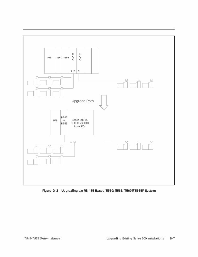
Upgrading Existing Series 500 Installations D-7TI545/TI555 System Manual
P/STI555
Series 505 I/O4, 8, or 16 slots
Local I/O
Upgrade Path
P/S TI560RCC
TI565
1 2 3
RCC
TI545or
Figure D-2 Upgrading an RS-485 Based TI560/TI565/TI560T/TI565P System

Upgrading Existing Series 500 InstallationsD-8 TI545/TI555 System Manual
D.4 Upgrading an RF Based TI560/TI565/TI560T/TI565P System
To upgrade an existing RF based TI560, TI560T, TI565, TI565P system,replace the existing programmable controller, including its chassis, powersupply and all installed boards with the TI505 base, power supply,TI545/TI555 controller, and RF/RS-485 converter. The upgrade is showngraphically in Figure D-3.
NOTE: Note that the TI545/TI555 cannot directly replace an hot backupHBU configuration.
1. If the series 500 remote I/O installation consists of more than onecoaxial (RF) remote I/O channel, combine these channels into a singleremote I/O channel. Refer to your existing controller’s documentationfor information about installation of a coaxial remote I/O channel.
2. Renumber your bases so that no two bases have the same number andso that base number 0 is not used.
3. Modify the controller’s I/O configuration to reflect the channel numberand base number changes.
4. Connect the resulting I/O channel to the TI545/TI555 system using thePPX:505–6860 RF to RS-485 converter.
Update time for a special function module is significantly faster when youinstall the module in the local base, versus a remote base. You can improveSF module performance, and scan performance, by replacing the Series 500SF modules with Series 505 SF modules and installing them in theTI545/TI555 local base.
If all SF modules cannot be installed in the local base, consider placinglow-activity SF modules, such as the ASCII, BASIC, or DCP modules, in aremote base. Place high-activity modules, such as the NIM or Peerlink, inthe local base.

Upgrading Existing Series 500 Installations D-9TI545/TI555 System Manual
P/STI555
Series 505 I/O4, 8, or 16 slots
Local I/O
Upgrade Path
P/S TI560RCC
TI565
1 2 3
RCC
TI545or
505–6860
Figure D-3 Upgrading an RF Based TI560/TI565/TI560T/TI565P System

Upgrading Existing Series 500 InstallationsD-10 TI545/TI555 System Manual
D.5 Installing a PPX:500–5114A RBC
With the PPX:500–5114A RBC you can select the state of the outputswhenever a communication error occurs. Previous models of the RBCautomatically set all outputs to off (0) when communication is lost. Youmust configure the RBC to freeze outputs in the state they were in whencommunication was lost, or to have them set to off (0).
The Series 500 output modules in the remote base have a selection switchfor the state of the outputs during a communication loss (Figure D-4). If theoutput modules in the remote base have a selection switch, the freezeselection will override the output module’s selection.
NOTE: If the RBC fails or the system loses power, the outputs will go off (0)regardless of the jumper selection.
OFF
FREEZE
(Factory Set)
Figure D-4 Series 500 RBC Switch Selection
Output StateSelection

Upgrading Existing Series 500 Installations D-11TI545/TI555 System Manual
To install the RBC, refer to Figure D-5 and follow the steps below.
1. Position the RBC so that the bezel is facing you.
2. Grasp the top and bottom of the RBC.
3. Carefully push the RBC into the slot until it mates with the back planeconnectors.
4. Tighten top and bottom bezel screws.
5. Connect the RBC to the RS-485 trunkline.
Remote Base Controller
Power Supply
Figure D-5 Installed Series 500 RBC
Installing aSeries 500 RBC

Upgrading Existing Series 500 InstallationsD-12 TI545/TI555 System Manual
Installing a PPX:500–5114A RBC (continued)
The RBC is equipped with a RS-232 port to program the TI545/TI555 CPUor, to troubleshoot from a remote I/O base. A baud rate thumbwheel (seeFigure D-6) is used to set the baud rate for this port.
Baud Rate Thumbwheel
Base Thumbwheel
LED Display
RemoteBase
Controller
Thumbwheel BaudNumber Rate
0 9600. . . . . . . . 1 2400. . . . . . . . 2 1200. . . . . . . . 3 300. . . . . . . . . 4 9600. . . . . . . . 5 2400. . . . . . . . 6 1200. . . . . . . . 7 300. . . . . . . . . 8 9600. . . . . . . . 9 2400. . . . . . . .
10 1200. . . . . . . . 11 300. . . . . . . . . 12 9600. . . . . . . . 13 2400. . . . . . . . 14 1200. . . . . . . . 15 300. . . . . . . . .
RS-485 I/O port 9-pin female
RS-232 port 25-pin female
Figure D-6 Series 500 Remote Base Controller and Baud Rate Settings
The base thumbwheel (Figure D-6) is used to assign a base number to theRBC for system identification. If you are using more than one RBC, eachRBC must be uniquely numbered. Refer to Table D-1 for assigning basenumbers. Base number 0 is reserved for the TI545/TI555 and must not beassigned to the RBC.
Setting Baud Rates
Assigning BaseNumbers
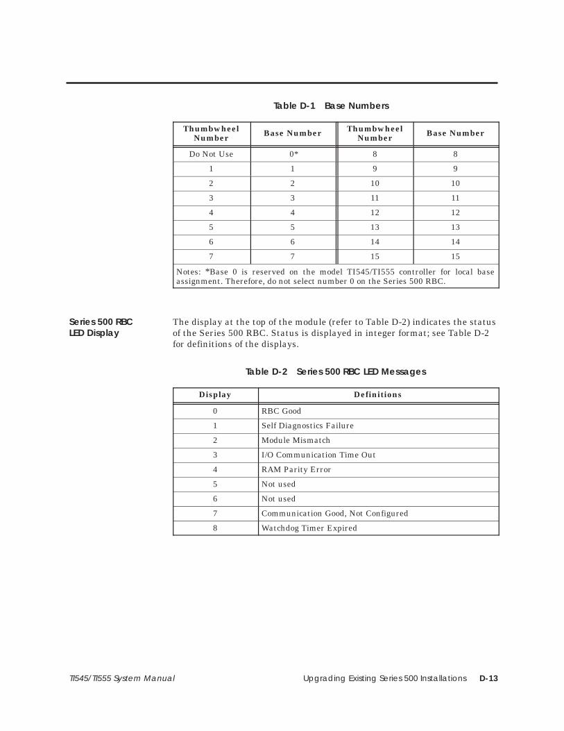
Upgrading Existing Series 500 Installations D-13TI545/TI555 System Manual
Table D-1 Base Numbers
ThumbwheelNumber Base Number Thumbwheel
Number Base Number
Do Not Use 0* 8 8
1 1 9 9
2 2 10 10
3 3 11 11
4 4 12 12
5 5 13 13
6 6 14 14
7 7 15 15
Notes: *Base 0 is reserved on the model TI545/TI555 controller for local baseassignment. Therefore, do not select number 0 on the Series 500 RBC.
The display at the top of the module (refer to Table D-2) indicates the statusof the Series 500 RBC. Status is displayed in integer format; see Table D-2for definitions of the displays.
Table D-2 Series 500 RBC LED Messages
Display Definitions
0 RBC Good
1 Self Diagnostics Failure
2 Module Mismatch
3 I/O Communication Time Out
4 RAM Parity Error
5 Not used
6 Not used
7 Communication Good, Not Configured
8 Watchdog Timer Expired
Series 500 RBCLED Display

Index-1
Index
AAssistance, calling for, 7-8
Auxiliary functionsdisplay failed I/O, 7-4restarting, 7-2run diagnostics, 7-4show diagnostic cell, 7-4used in troubleshooting, 7-2
BBase
series 500, RBC, installing and removing,D-11
series 505installing controller, 3-11–3-15installing RBC, 3-19panel mounting, 3-5rack mounting, 3-4
Battery, backupdescription, 1-7replacing, 3-13
Baud ratesseries 500, RBC, setting thumbwheel, D-12series 505, 3-15series 505 RBC, 3-16setting, 3-15
CCable
alternate cables, 4-13characteristics, 4-13connecting drop line, 4-9, 4-12, 4-14, 4-16connecting modems, overview, 4-18connecting to terminal block, 4-8, 4-10installing drop lines, 4-8, 4-10overview, 4-6resistance of line-to-line, 7-15routing guidelines, 4-4RS-485
connecting drop line, 4-8, 4-10
connecting terminal blocks, 4-17measuring resistance, 7-14preparing trunk line, 4-16
user-supplied equipment, 4-6
Cable routingin-ceiling, 4-5methods, 4-4mounting tap, 4-5surface duct, 4-5terminal block, 4-5under-floor, 4-5
Circuit breaker, guidelines for fuses/circuitbreakers, 2-7
Clock (real-time), 1-7
Communicating with controller, devices to use,1-5
Communication ports, description, 1-7
DDipswitches
back-up battery switch, 3-15baud rates, 3-15port selections, 3-14series 505 RBC, setting baud rate, 3-16setting controller, 3-13
EEEPROM
errors and corrections, 5-9installing, 5-6list of functions, 5-4overview, 5-2program
copying, 5-8editing, 5-10errors, 5-9
Electrical noiseavoiding, 2-8correcting, 2-9isolating from, 2-11

Index-2
Emergency, stop switch, 2-4
Enclosure, planning for PLC, 2-6
EPROMinstalling, 5-6overview, 5-3
EPROM/EEPROMcompatability, 5-2troubleshooting, 7-11using, 5-2
Errorscorrecting fatal errors, 7-7troubleshooting fatal, 7-7
FFatal errors, steps to clear, 7-8
Features, 1-2
Fuseguidelines for fuses/circuit breakers, 2-7series 505, replacing in power supply, 7-12
GGrounding
cabinet or rack, 2-14connections, 2-14controller, 2-14earth, 2-13planning for, 2-13sample connection, 2-15
HH1 support, 1-5
Hardware, description, 1-6
Hot backup, D-8
II/O modules
compatibility, determing of module, C-2
controller compatibility, C-2local, overview, 1-6mismatches, troubleshooting, 7-4remote, overview, 1-6serial number, C-4series 505
installing and removing, 3-21mixing, 3-21
troubleshooting, 7-4
I/O port, description, 1-7
Inch switch, location, 2-5
InstallingEEPROM and EPROM, 5-6planning for, 2-2series 500 RBC
in adapters, D-11in bases, D-11
series 505, 3-4power supply, 3-9
series 505 RBC, 3-19
Installing and removingseries 500 RBC, D-11series 505
I/O modules, 3-21power supply, 3-9RBC, 3-19
JJog switch, location, 2-5
LLocal area networks, supported, 1-5
MMemory, configuration, list of types, 6-4, 6-5
Modemconnecting, overview, 4-18dedicated line operation, 4-18, 4-19dial-up phone line, 4-19

Index-3
NNoise
avoiding electrical, 2-8isolating from, 2-11snubbing, contact noise, 2-9
PPower needs, planning for, 2-2
Power supplyconnecting input, 4-2series 505, 1-7
installing, 3-9installing and removing, 3-9power consumption, 3-9replacing fuse, 7-12troubleshooting, 7-12
Power-upmemory and mode status, 5-5procedures, 6-2
Printerconnecting, 4-20handshaking, 4-20overview, 4-20
Programcopying into EEPROM, 5-8editing in EEPROM, 5-10software, 1-8storage in EEPROM, 1-8storage in EPROM, 1-8
RRBC
series 500assigning base numbers, D-12installing and removing, D-11placing in bases, D-11setting baud rate, D-12
series 505assigning base numbers, 3-19description, 3-3installing and removing, 3-19installing in base, 3-19
setting baud rate, 3-16
RBE, support, 1-2
Restartlist of auxiliary functions, 7-3–7-16using auxiliary functions, 7-2
RF to RS-485 converter, D-8
SSafety
guidelines, 2-3inch switch, 2-5jog switch, 2-5operator safety switches, 2-4
Series 500, base numbers, assigning, D-12
Series 500 RBCinstalling and removing, D-11LED messages, D-13placing in bases, D-11setting baud rates, D-12
Series 505base
installing controller, 3-11–3-15models available, 3-3panel mounting, 3-5
models available, 3-3rack mounting, 3-4
models available, 3-3connecting base, 3-3dipswitch, ports, 3-14environmental specifications, A-2general specifications, A-3I/O modules, installing and removing, 3-21installing, flowchart, 3-2module power requirements, B-2power supply
installing and removing, 3-9replacing fuse, 7-12
specifications, power supply electrical, A-4
Series 505 RBCbase, installing, 3-19base numbers, assigning, 3-19dipswitch (factory), 3-17installing and removing, 3-19LED messages, 3-20

Index-4
Spare parts, list of, 7-16
Specifications, series 505general, A-3power supply electrical, A-4system specifications, A-2
Start-up, procedures, 6-2
Status words, using in troubleshooting, 7-10
Switch, emergency stop, 2-4
Switchesinch, 2-5jog, 2-5safety, 2-4
TTemperature, planning for PLC, 2-6
Thumbwheelsseries 500 RBC
assigning base numbers, D-12setting baud rate, D-12
series 505 RBC, assigning base numbers, 3-19
TIWAY, support, 1-5
Troubleshootingcable, RS-485, 7-14compare disk to PLC, 7-4EPROM/EEPROM, 7-11fatal errors, 7-7non-fatal errors, list of, 7-9reading LEDs, 7-6restart, 7-2series 505, power supply, 7-12using auxiliary functions, 7-2using status words, 7-10
UUpgrading
series 500 system, D-3–D-5TI560/TI565 system, D-6–D-7, D-8–D-9
WWiring
connecting input power, 4-2planning for installation, 2-12

SIMATIC and SINEC are trademarks of Siemens AG.
Series 505, Series 500, APT, CVU100, CVU1000, CVU10000, Peerlink, TISOFT, TIWAY, PCS, 386/ATM, and 7MT are trademarks ofSiemens Industrial Automation, Inc.
IBM and AT are registered trademarks of International Business Machines Incorporated.
MS-DOS is a registered trademark of Microsoft corporation.
Belden is a registered trademark of Cooper Industries, Inc.
TI505, TI520, TI520C, TI530, TI530C, TI530T, TI545, TI555, TI560, TI565, TI560T, and TI565P are trademarks of Texas InstrumentsIncorporated.
CSA is a registered trademark of the Canadian Standards Association.

Customer Registration
We would like to know what you think about our user manuals so that we can serve you better.How would you rate the quality of our manuals?
Excellent Good Fair Poor
AccuracyOrganizationClarityCompletenessOverall designSizeIndex
Would you be interested in giving us more detailed comments about our manuals?
Yes! Please send me a questionnaire.
No. Thanks anyway.
Your Name:
Title:
Telephone Number: ( )
Company Name:
Company Address:
Manual Name: SIMATIC TI545/555 System Manual Edition: Second
Manual Assembly Number: 2586546–0084 Date: 10/94
Order Number: PPX:545/555–8101-2

BUSINESS REPLY MAILFIRST CLASS PERMIT NO.3 JOHNSON CITY, TN
FOLD
FOLD
POSTAGE WILL BE PAID BY ADDRESSEE
NO POSTAGENECESSARYIF MAILED
IN THEUNITED STATES
ATTN: Technical Communications M/S 3519SIEMENS INDUSTRIAL AUTOMATION INC. 3000 BILL GARLAND RDP O BOX 1255JOHNSON CITY TN 37605–1255