Embed Size (px)
Citation preview
SIMATIC 505
Input/Output Modules
User Manual
!

Copyright 1994 by Siemens Industrial Automation, Inc. All Rights Reserved — Printed in USA
Reproduction, transmission or use of this document or contents is not permitted without express consent of Siemens Industrial Au-tomation, Inc. All rights, including rights created by patent grant or registration of a utility model or design, are reserved.
Since Siemens Industrial Automation, Inc. does not possess full access to data concerning all of the uses and applications of cus-tomer’s products, we do not assume responsibility either for customer product design or for any infringements of patents or rights ofothers which may result from our assistance.
Technical data is subject to change.
We check the contents of every manual for accuracy at the time it is approved for printing; however, there may be undetected errors.Any errors found will be corrected in subsequent editions. Any suggestions for improvement are welcomed.
MANUAL PUBLICATION HISTORY
SIMATIC 505 Input/Output Modules User ManualOrder Manual Number: PPX:505–8105–2Refer to this history in all correspondence and/or discussion about this manual.
Event Date Description
Original Issue 02/94 Original Issue (2803210–0001)(This manual supersedes the manual set PPX:505–8105–1.)
LIST OF EFFECTIVE PAGES
Pages Description Pages Description
Cover/Copyright OriginalHistory/Effective Pages Originaliii — xii Original
1-1 — 1-9 Original2-1 — 2-16 Original3-1 — 3-41 Original4-1 — 4-7 OriginalA-1 — A-24 OriginalIndex-1 — Index-2 OriginalRegistration Original
Contents iii
Contents
Preface xi. . . . . . . . . . . . . . . . . . . . . . . . . . . . . . . . . . . . . . . . . . . . . . . . . . . . . . . . . . . . . . . . . Other Manuals xii. . . . . . . . . . . . . . . . . . . . . . . . . . . . . . . . . . . . . . . . . . . . . . . . . . . . . . . . . . . . . . . . . . Agency Approvals xii. . . . . . . . . . . . . . . . . . . . . . . . . . . . . . . . . . . . . . . . . . . . . . . . . . . . . . . . . . . . . . For Assistance xii. . . . . . . . . . . . . . . . . . . . . . . . . . . . . . . . . . . . . . . . . . . . . . . . . . . . . . . . . . . . . . . . . .
Chapter 1 Discrete Input/Output and Relay Output Modules1.1 Module Descriptions 1-2. . . . . . . . . . . . . . . . . . . . . . . . . . . . . . . . . . . . . . . . . . . . . . . . . . . . . . . . . . . .
Discrete Input/Output Modules 1-2. . . . . . . . . . . . . . . . . . . . . . . . . . . . . . . . . . . . . . . . . . . . . . . . . . Relay Output Modules 1-2. . . . . . . . . . . . . . . . . . . . . . . . . . . . . . . . . . . . . . . . . . . . . . . . . . . . . . . . . . I/O Simulators 1-4. . . . . . . . . . . . . . . . . . . . . . . . . . . . . . . . . . . . . . . . . . . . . . . . . . . . . . . . . . . . . . . . . . . Operation of the Input Simulator Module Switches 1-5. . . . . . . . . . . . . . . . . . . . . . . . . . . . . . . .
1.2 Power Sources 1-6. . . . . . . . . . . . . . . . . . . . . . . . . . . . . . . . . . . . . . . . . . . . . . . . . . . . . . . . . . . . . . . . . . Discrete and Relay Modules 1-6. . . . . . . . . . . . . . . . . . . . . . . . . . . . . . . . . . . . . . . . . . . . . . . . . . . . .
1.3 LED Arrays 1-7. . . . . . . . . . . . . . . . . . . . . . . . . . . . . . . . . . . . . . . . . . . . . . . . . . . . . . . . . . . . . . . . . . . . . . Discrete I/O Modules 1-7. . . . . . . . . . . . . . . . . . . . . . . . . . . . . . . . . . . . . . . . . . . . . . . . . . . . . . . . . . . .
1.4 Fuses 1-8. . . . . . . . . . . . . . . . . . . . . . . . . . . . . . . . . . . . . . . . . . . . . . . . . . . . . . . . . . . . . . . . . . . . . . . . . . . Discrete Output Modules 1-8. . . . . . . . . . . . . . . . . . . . . . . . . . . . . . . . . . . . . . . . . . . . . . . . . . . . . . . . Relay Output Modules 1-9. . . . . . . . . . . . . . . . . . . . . . . . . . . . . . . . . . . . . . . . . . . . . . . . . . . . . . . . . .
Chapter 2 Word Input and Output Modules2.1 Module Descriptions 2-2. . . . . . . . . . . . . . . . . . . . . . . . . . . . . . . . . . . . . . . . . . . . . . . . . . . . . . . . . . . .
Word Input Module 2-2. . . . . . . . . . . . . . . . . . . . . . . . . . . . . . . . . . . . . . . . . . . . . . . . . . . . . . . . . . . . . Word Output Module 2-3. . . . . . . . . . . . . . . . . . . . . . . . . . . . . . . . . . . . . . . . . . . . . . . . . . . . . . . . . . . Data Word Format 2-4. . . . . . . . . . . . . . . . . . . . . . . . . . . . . . . . . . . . . . . . . . . . . . . . . . . . . . . . . . . . . .
2.2 Power Sources 2-5. . . . . . . . . . . . . . . . . . . . . . . . . . . . . . . . . . . . . . . . . . . . . . . . . . . . . . . . . . . . . . . . . . Power Supplies 2-5. . . . . . . . . . . . . . . . . . . . . . . . . . . . . . . . . . . . . . . . . . . . . . . . . . . . . . . . . . . . . . . . . Early Power Failure 2-5. . . . . . . . . . . . . . . . . . . . . . . . . . . . . . . . . . . . . . . . . . . . . . . . . . . . . . . . . . . . . .
2.3 LED Arrays 2-6. . . . . . . . . . . . . . . . . . . . . . . . . . . . . . . . . . . . . . . . . . . . . . . . . . . . . . . . . . . . . . . . . . . . . . LED Status Indicators 2-6. . . . . . . . . . . . . . . . . . . . . . . . . . . . . . . . . . . . . . . . . . . . . . . . . . . . . . . . . . . .
2.4 Fuses 2-7. . . . . . . . . . . . . . . . . . . . . . . . . . . . . . . . . . . . . . . . . . . . . . . . . . . . . . . . . . . . . . . . . . . . . . . . . . . Fuse Locations 2-7. . . . . . . . . . . . . . . . . . . . . . . . . . . . . . . . . . . . . . . . . . . . . . . . . . . . . . . . . . . . . . . . . .
2.5 Timing Characteristics 2-8. . . . . . . . . . . . . . . . . . . . . . . . . . . . . . . . . . . . . . . . . . . . . . . . . . . . . . . . . . . Input Scan 2-8. . . . . . . . . . . . . . . . . . . . . . . . . . . . . . . . . . . . . . . . . . . . . . . . . . . . . . . . . . . . . . . . . . . . . Output Scan 2-8. . . . . . . . . . . . . . . . . . . . . . . . . . . . . . . . . . . . . . . . . . . . . . . . . . . . . . . . . . . . . . . . . . .
iv Contents
2.6 Jumper Options 2-9. . . . . . . . . . . . . . . . . . . . . . . . . . . . . . . . . . . . . . . . . . . . . . . . . . . . . . . . . . . . . . . . . Selecting Options 2-9. . . . . . . . . . . . . . . . . . . . . . . . . . . . . . . . . . . . . . . . . . . . . . . . . . . . . . . . . . . . . . . Word Input Data Active Level 2-9. . . . . . . . . . . . . . . . . . . . . . . . . . . . . . . . . . . . . . . . . . . . . . . . . . . Word Output Data Active Level 2-10. . . . . . . . . . . . . . . . . . . . . . . . . . . . . . . . . . . . . . . . . . . . . . . . . Word Input Strobe Active Level 2-11. . . . . . . . . . . . . . . . . . . . . . . . . . . . . . . . . . . . . . . . . . . . . . . . . . Word Output Strobe Active Level 2-11. . . . . . . . . . . . . . . . . . . . . . . . . . . . . . . . . . . . . . . . . . . . . . . . Word Input Internal Resistance 2-12. . . . . . . . . . . . . . . . . . . . . . . . . . . . . . . . . . . . . . . . . . . . . . . . . . Word Input Drive Capabilities 2-12. . . . . . . . . . . . . . . . . . . . . . . . . . . . . . . . . . . . . . . . . . . . . . . . . . . . Word Output Drive Capabilities 2-13. . . . . . . . . . . . . . . . . . . . . . . . . . . . . . . . . . . . . . . . . . . . . . . . . . Word Input Strobe Source 2-13. . . . . . . . . . . . . . . . . . . . . . . . . . . . . . . . . . . . . . . . . . . . . . . . . . . . . . . Word Output Channel Operation 2-15. . . . . . . . . . . . . . . . . . . . . . . . . . . . . . . . . . . . . . . . . . . . . . . . Eight- and Single- Channel Modes 2-16. . . . . . . . . . . . . . . . . . . . . . . . . . . . . . . . . . . . . . . . . . . . . . .
Chapter 3 Installing the Modules3.1 Installing the Modules 3-2. . . . . . . . . . . . . . . . . . . . . . . . . . . . . . . . . . . . . . . . . . . . . . . . . . . . . . . . . . .
Overview 3-2. . . . . . . . . . . . . . . . . . . . . . . . . . . . . . . . . . . . . . . . . . . . . . . . . . . . . . . . . . . . . . . . . . . . . . . Guidelines 3-2. . . . . . . . . . . . . . . . . . . . . . . . . . . . . . . . . . . . . . . . . . . . . . . . . . . . . . . . . . . . . . . . . . . . . .
3.2 Wiring the Discrete Input and Output Modules 3-3. . . . . . . . . . . . . . . . . . . . . . . . . . . . . . . . . . . . Pin-outs for Discrete Input and Output Modules 3-3. . . . . . . . . . . . . . . . . . . . . . . . . . . . . . . . . . .
3.3 Wiring the Relay Output Modules 3-14. . . . . . . . . . . . . . . . . . . . . . . . . . . . . . . . . . . . . . . . . . . . . . . . Pin-outs for Relay Output Modules 3-14. . . . . . . . . . . . . . . . . . . . . . . . . . . . . . . . . . . . . . . . . . . . . . .
3.4 Wiring the Word Input and Output Modules 3-19. . . . . . . . . . . . . . . . . . . . . . . . . . . . . . . . . . . . . . . Pin-outs for Word Input and Output Modules 3-19. . . . . . . . . . . . . . . . . . . . . . . . . . . . . . . . . . . . . Avoiding Noise 3-21. . . . . . . . . . . . . . . . . . . . . . . . . . . . . . . . . . . . . . . . . . . . . . . . . . . . . . . . . . . . . . . . . Connections and Terminations 3-21. . . . . . . . . . . . . . . . . . . . . . . . . . . . . . . . . . . . . . . . . . . . . . . . . .
3.5 Field Wiring 3-24. . . . . . . . . . . . . . . . . . . . . . . . . . . . . . . . . . . . . . . . . . . . . . . . . . . . . . . . . . . . . . . . . . . . . Wiring Recommendations 3-24. . . . . . . . . . . . . . . . . . . . . . . . . . . . . . . . . . . . . . . . . . . . . . . . . . . . . . . Wiring the Terminal Block 3-25. . . . . . . . . . . . . . . . . . . . . . . . . . . . . . . . . . . . . . . . . . . . . . . . . . . . . . . . Connecting the Terminal Block 3-27. . . . . . . . . . . . . . . . . . . . . . . . . . . . . . . . . . . . . . . . . . . . . . . . . . Typical Connections 3-28. . . . . . . . . . . . . . . . . . . . . . . . . . . . . . . . . . . . . . . . . . . . . . . . . . . . . . . . . . . .
3.6 Connecting Discrete Output Modules 3-37. . . . . . . . . . . . . . . . . . . . . . . . . . . . . . . . . . . . . . . . . . . . AC and DC Output Modules 3-37. . . . . . . . . . . . . . . . . . . . . . . . . . . . . . . . . . . . . . . . . . . . . . . . . . . .
3.7 Loopback Configuration 3-38. . . . . . . . . . . . . . . . . . . . . . . . . . . . . . . . . . . . . . . . . . . . . . . . . . . . . . . . Discrete Input and Output Modules 3-38. . . . . . . . . . . . . . . . . . . . . . . . . . . . . . . . . . . . . . . . . . . . . .
3.8 Configuring I/O 3-39. . . . . . . . . . . . . . . . . . . . . . . . . . . . . . . . . . . . . . . . . . . . . . . . . . . . . . . . . . . . . . . . . Discrete I/O Modules and I/O Simulators 3-39. . . . . . . . . . . . . . . . . . . . . . . . . . . . . . . . . . . . . . . . . Relay Output Modules 3-40. . . . . . . . . . . . . . . . . . . . . . . . . . . . . . . . . . . . . . . . . . . . . . . . . . . . . . . . . . Word Input and Word Output Modules 3-41. . . . . . . . . . . . . . . . . . . . . . . . . . . . . . . . . . . . . . . . . . .
Contents v
Chapter 4 Troubleshooting4.1 LED Status Indicators 4-2. . . . . . . . . . . . . . . . . . . . . . . . . . . . . . . . . . . . . . . . . . . . . . . . . . . . . . . . . . . .
Discrete Input and Output Modules 4-2. . . . . . . . . . . . . . . . . . . . . . . . . . . . . . . . . . . . . . . . . . . . . . Relay Output Modules 4-3. . . . . . . . . . . . . . . . . . . . . . . . . . . . . . . . . . . . . . . . . . . . . . . . . . . . . . . . . . Word Input and Output Modules 4-4. . . . . . . . . . . . . . . . . . . . . . . . . . . . . . . . . . . . . . . . . . . . . . . . For Assistance 4-4. . . . . . . . . . . . . . . . . . . . . . . . . . . . . . . . . . . . . . . . . . . . . . . . . . . . . . . . . . . . . . . . . .
4.2 Replacing a Fuse 4-5. . . . . . . . . . . . . . . . . . . . . . . . . . . . . . . . . . . . . . . . . . . . . . . . . . . . . . . . . . . . . . . Discrete Output, Relay Output, Word Input and Word Output Modules 4-5. . . . . . . . . . . . For Assistance 4-5. . . . . . . . . . . . . . . . . . . . . . . . . . . . . . . . . . . . . . . . . . . . . . . . . . . . . . . . . . . . . . . . . .
4.3 Replacing a Relay 4-6. . . . . . . . . . . . . . . . . . . . . . . . . . . . . . . . . . . . . . . . . . . . . . . . . . . . . . . . . . . . . . Relay Output Modules 4-6. . . . . . . . . . . . . . . . . . . . . . . . . . . . . . . . . . . . . . . . . . . . . . . . . . . . . . . . . . Replacing a Damaged Relay 4-6. . . . . . . . . . . . . . . . . . . . . . . . . . . . . . . . . . . . . . . . . . . . . . . . . . . For Assistance 4-7. . . . . . . . . . . . . . . . . . . . . . . . . . . . . . . . . . . . . . . . . . . . . . . . . . . . . . . . . . . . . . . . . .
Appendix A SpecificationsA.1 Environmental Specifications A-2. . . . . . . . . . . . . . . . . . . . . . . . . . . . . . . . . . . . . . . . . . . . . . . . . . . .
A.2 Electrical Specifications A-3. . . . . . . . . . . . . . . . . . . . . . . . . . . . . . . . . . . . . . . . . . . . . . . . . . . . . . . . . Discrete Input Modules A-3. . . . . . . . . . . . . . . . . . . . . . . . . . . . . . . . . . . . . . . . . . . . . . . . . . . . . . . . . . Discrete Output Modules A-9. . . . . . . . . . . . . . . . . . . . . . . . . . . . . . . . . . . . . . . . . . . . . . . . . . . . . . . . Relay Output Modules A-17. . . . . . . . . . . . . . . . . . . . . . . . . . . . . . . . . . . . . . . . . . . . . . . . . . . . . . . . . . Word Input Module A-21. . . . . . . . . . . . . . . . . . . . . . . . . . . . . . . . . . . . . . . . . . . . . . . . . . . . . . . . . . . . . Word Output Module A-22. . . . . . . . . . . . . . . . . . . . . . . . . . . . . . . . . . . . . . . . . . . . . . . . . . . . . . . . . . . I/O Simulators A-23. . . . . . . . . . . . . . . . . . . . . . . . . . . . . . . . . . . . . . . . . . . . . . . . . . . . . . . . . . . . . . . . . . .
A.3 Terminal Block Worksheet A-24. . . . . . . . . . . . . . . . . . . . . . . . . . . . . . . . . . . . . . . . . . . . . . . . . . . . . . .
vi Contents
List of Figures
1-1 TI505 Discrete Input, Discrete Output, and Relay Output Modules 1-3. . . . . . . . . . . . . . . . . .
1-2 LED Array for Discrete Input, Discrete Output, I/O Simulators, and Relay Output Modules 1-7. . . . . . . . . . . . . . . . . . . . . . . . . . . . . . . . . . . . . . . . . . . . . . . . . . . . . . . . . .
2-1 SIMATIC TI505 Word Input and Word Output Modules 2-2. . . . . . . . . . . . . . . . . . . . . . . . . . . . .
2-2 Input Circuit for Data Lines and Output Circuit for Module-Generated Strobes 2-3. . . . .
2-3 Output Circuit for Data and Strobe Lines 2-4. . . . . . . . . . . . . . . . . . . . . . . . . . . . . . . . . . . . . . . . .
2-4 Data Word Format for Word Input and Word Output Modules 2-4. . . . . . . . . . . . . . . . . . . . .
2-5 Early Power Failure Output (on Terminal Block) 2-5. . . . . . . . . . . . . . . . . . . . . . . . . . . . . . . . . . . .
2-6 LED Status Indicator for Word Input and Word Output Modules 2-6. . . . . . . . . . . . . . . . . . . .
2-7 Data Active Level Jumper (on Terminal Block) 2-10. . . . . . . . . . . . . . . . . . . . . . . . . . . . . . . . . . . .
2-8 Strobe Active Level Jumper (on Terminal Block) 2-12. . . . . . . . . . . . . . . . . . . . . . . . . . . . . . . . . .
2-9 Internal Resistance Jumper (on Terminal Block) 2-12. . . . . . . . . . . . . . . . . . . . . . . . . . . . . . . . . . .
2-10 Timing of Module-Supplied Strobes (High True) 2-13. . . . . . . . . . . . . . . . . . . . . . . . . . . . . . . . . . . .
2-11 Timing of User-Supplied Strobes (High True) 2-14. . . . . . . . . . . . . . . . . . . . . . . . . . . . . . . . . . . . . . .
2-12 Word Input Strobe Source Jumper (on Terminal Block) 2-15. . . . . . . . . . . . . . . . . . . . . . . . . . . .
2-13 Word Output Channel Operation Jumper (on Terminal Block) 2-15. . . . . . . . . . . . . . . . . . . . .
2-14 Strobe Timing - Eight Channel Mode (High True) 2-16. . . . . . . . . . . . . . . . . . . . . . . . . . . . . . . . . .
2-15 Strobe Timing - Single Channel Mode (High True) 2-16. . . . . . . . . . . . . . . . . . . . . . . . . . . . . . . . .
3-1 Inserting the Module into the Base 3-2. . . . . . . . . . . . . . . . . . . . . . . . . . . . . . . . . . . . . . . . . . . . . . .
3-2 Example of Terminal Block Wiring 3-3. . . . . . . . . . . . . . . . . . . . . . . . . . . . . . . . . . . . . . . . . . . . . . . .
3-3 Example of Terminal Block Wiring on 32-Point Relay Output Module 3-14. . . . . . . . . . . . . . . .
3-4 Blocking Diodes for Multiple Thumbwheels: Word Input Modules 3-23. . . . . . . . . . . . . . . . . . .
3-5 Terminal Blocks 3-26. . . . . . . . . . . . . . . . . . . . . . . . . . . . . . . . . . . . . . . . . . . . . . . . . . . . . . . . . . . . . . . . .
3-6 Installing the Terminal Block 3-27. . . . . . . . . . . . . . . . . . . . . . . . . . . . . . . . . . . . . . . . . . . . . . . . . . . . . .
3-7 Typical Sinking Connection for 32–Point Discrete Input Modules (PPX:505–4032(A),PPX:505–4132, PPX:505–4232(A), PPX:505–4332, and PPX:505–4432(A)) 3-28. . . . . . . . . . . . . .
3-8 Typical Sinking Connection for a 16–Point Discrete Input Module (PPX:505–4316–A) 3-29.
3-9 Typical Sourcing Connection for 8-Point AC Discrete Output Modules (PPX:505–4608 and PPX:505–4808) 3-30. . . . . . . . . . . . . . . . . . . . . . . . . . . . . . . . . . . . . . . . . . . . . . .
3-10 Typical Connection for Discrete Sourcing Output Modules (PPX:505–4508, PPX:505–4708,PPX:505–4516, PPX:505–4716, PPX:505–4532, and PPX:505–4732) 3-31. . . . . . . . . . . . . . . . . . .
3-11 Typical Connections for Discrete Sinking Output Modules (PPX:505–3508, PPX:505–3516,PPX:505–3532, PPX:505–3708, PPX:505–3716, and PPX:505–3732) 3-32. . . . . . . . . . . . . . . . . . .
3-12 Typical Connection for an 8–Point Relay Output Module (PPX:505–4908) 3-33. . . . . . . . . . .
3-13 Typical Connections for an 8–Point Relay Output Module (PPX:505–5417) 3-34. . . . . . . . . .
3-14 Typical Connections for an 8–Point Relay Output Module (PPX:505–5518) 3-35. . . . . . . . . .
3-15 Typical Connections for a Word Input or Output Module 3-36. . . . . . . . . . . . . . . . . . . . . . . . . .
3-16 Sample Discrete I/O Module Definition Chart 3-39. . . . . . . . . . . . . . . . . . . . . . . . . . . . . . . . . . . . .
3-17 Sample Relay Output Module Definition Chart 3-40. . . . . . . . . . . . . . . . . . . . . . . . . . . . . . . . . . .
3-18 Sample Word I/O Module Definition Chart 3-41. . . . . . . . . . . . . . . . . . . . . . . . . . . . . . . . . . . . . . . .
Contents vii
4-1 Replacing a Relay 4-7. . . . . . . . . . . . . . . . . . . . . . . . . . . . . . . . . . . . . . . . . . . . . . . . . . . . . . . . . . . . . .
A-1 Volt-Ampere Curve for PPX:505–40xx(A) Modules A-3. . . . . . . . . . . . . . . . . . . . . . . . . . . . . . . . . A-2 Volt-Ampere Curve for PPX:505–41xx Modules A-4. . . . . . . . . . . . . . . . . . . . . . . . . . . . . . . . . . . . A-3 Volt-Ampere Curve for PPX:505–42xx(–A) Modules A-5. . . . . . . . . . . . . . . . . . . . . . . . . . . . . . . . A-4 Volt-Ampere Curve for PPX:505–43xx Modules A-6. . . . . . . . . . . . . . . . . . . . . . . . . . . . . . . . . . . . A-5 Volt-Ampere Curve for PPX:505–4316–A Modules A-7. . . . . . . . . . . . . . . . . . . . . . . . . . . . . . . . . A-6 Volt-Ampere Curve for PPX:505–44xx Modules A-8. . . . . . . . . . . . . . . . . . . . . . . . . . . . . . . . . . . . A-7 Derating Curves for PPX:505–35xx and PPX:505–45xx Modules A-10. . . . . . . . . . . . . . . . . . . . . A-8 Derating Curves for PPX:505–46xx A-12. . . . . . . . . . . . . . . . . . . . . . . . . . . . . . . . . . . . . . . . . . . . . . . . A-9 Derating Curves for PPX:505–37xx and PPX:505–47xx A-14. . . . . . . . . . . . . . . . . . . . . . . . . . . . . . A-1 Derating Curves for PPX:505–48xx A-16. . . . . . . . . . . . . . . . . . . . . . . . . . . . . . . . . . . . . . . . . . . . . . . . A-11 Derating Curves for PPX:505–49xx A-18. . . . . . . . . . . . . . . . . . . . . . . . . . . . . . . . . . . . . . . . . . . . . . . . A-12 I/O Terminal Worksheet A-24. . . . . . . . . . . . . . . . . . . . . . . . . . . . . . . . . . . . . . . . . . . . . . . . . . . . . . . . . .
viii Contents
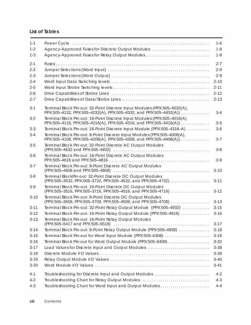
List of Tables
1-1 Power Cycle 1-6. . . . . . . . . . . . . . . . . . . . . . . . . . . . . . . . . . . . . . . . . . . . . . . . . . . . . . . . . . . . . . . . . . . 1-2 Agency-Approved Fuses for Discrete Output Modules 1-8. . . . . . . . . . . . . . . . . . . . . . . . . . . . 1-3 Agency-Approved Fuses for Relay Output Modules 1-9. . . . . . . . . . . . . . . . . . . . . . . . . . . . . . .
2-1 Fuses 2-7. . . . . . . . . . . . . . . . . . . . . . . . . . . . . . . . . . . . . . . . . . . . . . . . . . . . . . . . . . . . . . . . . . . . . . . . . . . 2-2 Jumper Selections (Word Input) 2-9. . . . . . . . . . . . . . . . . . . . . . . . . . . . . . . . . . . . . . . . . . . . . . . . . . 2-3 Jumper Selections (Word Output) 2-9. . . . . . . . . . . . . . . . . . . . . . . . . . . . . . . . . . . . . . . . . . . . . . . . 2-4 Word Input Data Switching levels 2-10. . . . . . . . . . . . . . . . . . . . . . . . . . . . . . . . . . . . . . . . . . . . . . . . 2-5 Word Input Strobe Switching levels 2-11. . . . . . . . . . . . . . . . . . . . . . . . . . . . . . . . . . . . . . . . . . . . . . . 2-6 Drive Capabilities of Strobe Lines 2-12. . . . . . . . . . . . . . . . . . . . . . . . . . . . . . . . . . . . . . . . . . . . . . . . 2-7 Drive Capabilities of Data/Strobe Lines 2-13. . . . . . . . . . . . . . . . . . . . . . . . . . . . . . . . . . . . . . . . . . .
3-1 Terminal Block Pin-out: 32-Point Discrete Input Modules (PPX:505–4032(A), PPX:505–4132, PPX:505–4232(A), PPX:505–4332, and PPX:505–4432(A)) 3-4. . . . . . . . . . . . . .
3-2 Terminal Block Pin-out: 16-Point Discrete Input Modules (PPX:505–4016(A)PPX:505–4116, PPX:505–4216(A), PPX:505–4316, and PPX:505–4416(A)) 3-5. . . . . . . . . . . . . .
3-3 Terminal Block Pin-out: 16-Point Discrete Input Module (PPX:505–4316–A) 3-6. . . . . . . . . . . 3-4 Terminal Block Pin-out: 8-Point Discrete Input Modules (PPX:505–4008(A),
PPX:505–4108, PPX:505–4208(A), PPX:505–4308, and PPX:505–4408(A)) 3-7. . . . . . . . . . . . . . 3-5 Terminal Block Pin-out: 32-Point Discrete AC Output Modules
(PPX:505–4632 and PPX:505–4832) 3-8. . . . . . . . . . . . . . . . . . . . . . . . . . . . . . . . . . . . . . . . . . . . . . . 3-6 Terminal Block Pin-out: 16-Point Discrete AC Output Modules
PPX:505–4616 and PPX:505–4816 3-9. . . . . . . . . . . . . . . . . . . . . . . . . . . . . . . . . . . . . . . . . . . . . . . . . 3-7 Terminal Block Pin-out: 8-Point Discrete AC Output Modules
(PPX:505–4608 and PPX:505–4808) 3-10. . . . . . . . . . . . . . . . . . . . . . . . . . . . . . . . . . . . . . . . . . . . . . . 3-8 Terminal BlockPin-out: 32-Point Discrete DC Output Modules
(PPX:505–3532, PPX:505–3732, PPX:505–4532, and PPX:505–4732) 3-11. . . . . . . . . . . . . . . . . . . 3-9 Terminal Block Pin-out: 16-Point Discrete DC Output Modules
(PPX:505–3516, PPX:505–3716, PPX:505–4516, and PPX:505–4716) 3-12. . . . . . . . . . . . . . . . . . . 3-10 Terminal Block Pin-out: 8-Point Discrete DC Output Modules
(PPX:505–3508, PPX:505–3708, PPX:505–4508, and PPX:505–4708) 3-13. . . . . . . . . . . . . . . . . . . 3-11 Terminal Block Pin-out: 32-Point Relay Output Module (PPX:505–4932) 3-15. . . . . . . . . . . . . 3-12 Terminal Block Pin-out: 16-Point Relay Output Module (PPX:505–4916) 3-16. . . . . . . . . . . . . . 3-13 Terminal Block Pin-out: 16-Point Relay Output Modules
(PPX:505–5417 and PPX:505–5518) 3-17. . . . . . . . . . . . . . . . . . . . . . . . . . . . . . . . . . . . . . . . . . . . . . . 3-14 Terminal Block Pin-out: 8-Point Relay Output Module (PPX:505–4908) 3-18. . . . . . . . . . . . . . . 3-15 Terminal Block Pin-out for Word Input Module (PPX:505–6308) 3-19. . . . . . . . . . . . . . . . . . . . . . 3-16 Terminal Block Pin-out for Word Output Module (PPX:505–6408) 3-20. . . . . . . . . . . . . . . . . . . . 3-17 Load Values for Discrete Input and Output Modules 3-38. . . . . . . . . . . . . . . . . . . . . . . . . . . . . . 3-18 Discrete Module I/O Values 3-39. . . . . . . . . . . . . . . . . . . . . . . . . . . . . . . . . . . . . . . . . . . . . . . . . . . . . . 3-19 Relay Output Module I/O Values 3-40. . . . . . . . . . . . . . . . . . . . . . . . . . . . . . . . . . . . . . . . . . . . . . . . . 3-20 Word Module I/O Values 3-41. . . . . . . . . . . . . . . . . . . . . . . . . . . . . . . . . . . . . . . . . . . . . . . . . . . . . . . .
4-1 Troubleshooting for Discrete Input and Output Modules 4-2. . . . . . . . . . . . . . . . . . . . . . . . . . . 4-2 Troubleshooting Chart for Relay Output Modules 4-3. . . . . . . . . . . . . . . . . . . . . . . . . . . . . . . . . 4-3 Troubleshooting Chart for Word Input and Output Modules 4-4. . . . . . . . . . . . . . . . . . . . . . . .
Contents ix
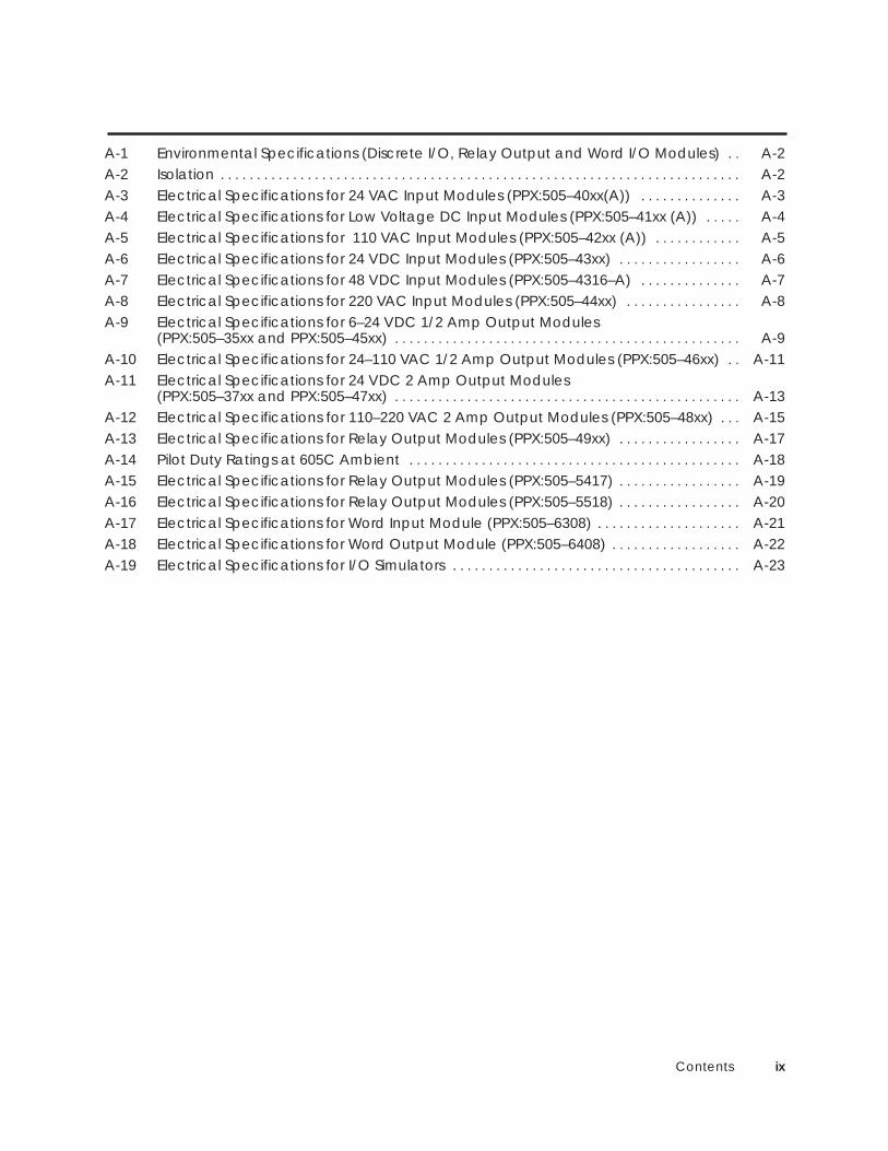
A-1 Environmental Specifications (Discrete I/O, Relay Output and Word I/O Modules) A-2. . A-2 Isolation A-2. . . . . . . . . . . . . . . . . . . . . . . . . . . . . . . . . . . . . . . . . . . . . . . . . . . . . . . . . . . . . . . . . . . . . . . . A-3 Electrical Specifications for 24 VAC Input Modules (PPX:505–40xx(A)) A-3. . . . . . . . . . . . . . A-4 Electrical Specifications for Low Voltage DC Input Modules (PPX:505–41xx (A)) A-4. . . . . A-5 Electrical Specifications for 110 VAC Input Modules (PPX:505–42xx (A)) A-5. . . . . . . . . . . . A-6 Electrical Specifications for 24 VDC Input Modules (PPX:505–43xx) A-6. . . . . . . . . . . . . . . . . A-7 Electrical Specifications for 48 VDC Input Modules (PPX:505–4316–A) A-7. . . . . . . . . . . . . . A-8 Electrical Specifications for 220 VAC Input Modules (PPX:505–44xx) A-8. . . . . . . . . . . . . . . . A-9 Electrical Specifications for 6–24 VDC 1/2 Amp Output Modules
(PPX:505–35xx and PPX:505–45xx) A-9. . . . . . . . . . . . . . . . . . . . . . . . . . . . . . . . . . . . . . . . . . . . . . . . A-10 Electrical Specifications for 24–110 VAC 1/2 Amp Output Modules (PPX:505–46xx) A-11. . A-11 Electrical Specifications for 24 VDC 2 Amp Output Modules
(PPX:505–37xx and PPX:505–47xx) A-13. . . . . . . . . . . . . . . . . . . . . . . . . . . . . . . . . . . . . . . . . . . . . . . . A-12 Electrical Specifications for 110–220 VAC 2 Amp Output Modules (PPX:505–48xx) A-15. . . A-13 Electrical Specifications for Relay Output Modules (PPX:505–49xx) A-17. . . . . . . . . . . . . . . . . A-14 Pilot Duty Ratings at 605C Ambient A-18. . . . . . . . . . . . . . . . . . . . . . . . . . . . . . . . . . . . . . . . . . . . . . A-15 Electrical Specifications for Relay Output Modules (PPX:505–5417) A-19. . . . . . . . . . . . . . . . . A-16 Electrical Specifications for Relay Output Modules (PPX:505–5518) A-20. . . . . . . . . . . . . . . . . A-17 Electrical Specifications for Word Input Module (PPX:505–6308) A-21. . . . . . . . . . . . . . . . . . . . A-18 Electrical Specifications for Word Output Module (PPX:505–6408) A-22. . . . . . . . . . . . . . . . . . A-19 Electrical Specifications for I/O Simulators A-23. . . . . . . . . . . . . . . . . . . . . . . . . . . . . . . . . . . . . . . .
Preface xiSIMATIC 505 Input/Output Modules User Manual
Preface
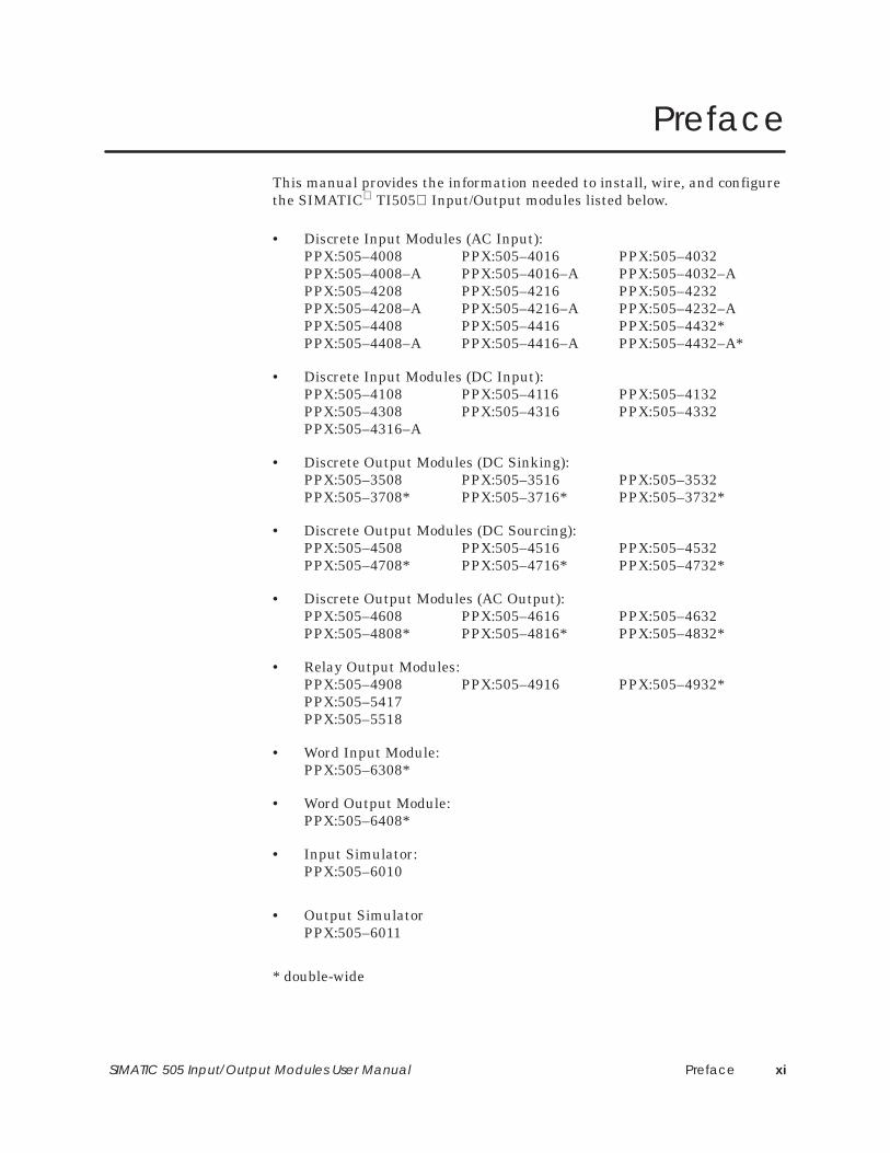
This manual provides the information needed to install, wire, and configurethe SIMATIC TI505 Input/Output modules listed below.
• Discrete Input Modules (AC Input):PPX:505–4008 PPX:505–4016 PPX:505–4032PPX:505–4008–A PPX:505–4016–A PPX:505–4032–APPX:505–4208 PPX:505–4216 PPX:505–4232PPX:505–4208–A PPX:505–4216–A PPX:505–4232–APPX:505–4408 PPX:505–4416 PPX:505–4432*PPX:505–4408–A PPX:505–4416–A PPX:505–4432–A*
• Discrete Input Modules (DC Input):PPX:505–4108 PPX:505–4116 PPX:505–4132PPX:505–4308 PPX:505–4316 PPX:505–4332PPX:505–4316–A
• Discrete Output Modules (DC Sinking):PPX:505–3508 PPX:505–3516 PPX:505–3532PPX:505–3708* PPX:505–3716* PPX:505–3732*
• Discrete Output Modules (DC Sourcing):PPX:505–4508 PPX:505–4516 PPX:505–4532PPX:505–4708* PPX:505–4716* PPX:505–4732*
• Discrete Output Modules (AC Output):PPX:505–4608 PPX:505–4616 PPX:505–4632PPX:505–4808* PPX:505–4816* PPX:505–4832*
• Relay Output Modules:PPX:505–4908 PPX:505–4916 PPX:505–4932*PPX:505–5417PPX:505–5518
• Word Input Module:PPX:505–6308*
• Word Output Module:PPX:505–6408*
• Input Simulator:PPX:505–6010
• Output SimulatorPPX:505–6011
* double-wide
Prefacexii SIMATIC 505 Input/Output Modules User Manual
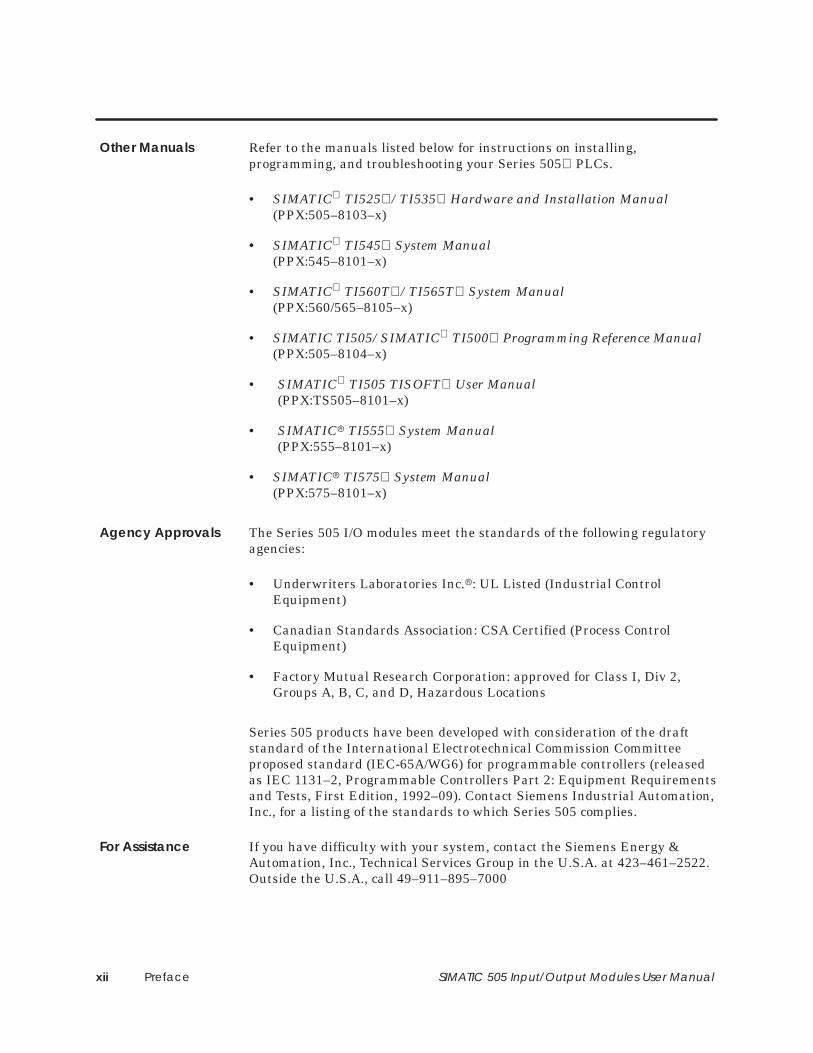
Refer to the manuals listed below for instructions on installing,programming, and troubleshooting your Series 505 PLCs.
• SIMATIC TI525 /TI535 Hardware and Installation Manual(PPX:505–8103–x)
• SIMATIC TI545 System Manual(PPX:545–8101–x)
• SIMATIC TI560T /TI565T System Manual(PPX:560/565–8105–x)
• SIMATIC TI505/SIMATIC TI500 Programming Reference Manual(PPX:505–8104–x)
• SIMATIC TI505 TISOFT User Manual(PPX:TS505–8101–x)
• SIMATIC TI555 System Manual(PPX:555–8101–x)
• SIMATIC TI575 System Manual(PPX:575–8101–x)
The Series 505 I/O modules meet the standards of the following regulatoryagencies:
• Underwriters Laboratories Inc.: UL Listed (Industrial ControlEquipment)
• Canadian Standards Association: CSA Certified (Process ControlEquipment)
• Factory Mutual Research Corporation: approved for Class I, Div 2,Groups A, B, C, and D, Hazardous Locations
Series 505 products have been developed with consideration of the draftstandard of the International Electrotechnical Commission Committeeproposed standard (IEC-65A/WG6) for programmable controllers (releasedas IEC 1131–2, Programmable Controllers Part 2: Equipment Requirementsand Tests, First Edition, 1992–09). Contact Siemens Industrial Automation,Inc., for a listing of the standards to which Series 505 complies.
If you have difficulty with your system, contact the Siemens Energy &Automation, Inc., Technical Services Group in the U.S.A. at 423–461–2522.Outside the U.S.A., call 49–911–895–7000
Other Manuals
Agency Approvals
For Assistance
Discrete Input and Output Modules 1-1SIMATIC 505 Input/Output Modules User Manual
Chapter 1
Discrete Input and Output Modules
1.1 Module Descriptions 1-2. . . . . . . . . . . . . . . . . . . . . . . . . . . . . . . . . . . . . . . . . . . . . . . . . . . . . . . . . . . . Discrete Input/Output Modules 1-2. . . . . . . . . . . . . . . . . . . . . . . . . . . . . . . . . . . . . . . . . . . . . . . . . . Relay Output Modules 1-2. . . . . . . . . . . . . . . . . . . . . . . . . . . . . . . . . . . . . . . . . . . . . . . . . . . . . . . . . . I/O Simulators 1-4. . . . . . . . . . . . . . . . . . . . . . . . . . . . . . . . . . . . . . . . . . . . . . . . . . . . . . . . . . . . . . . . . . . Operation of the Input Simulator Module Switches 1-5. . . . . . . . . . . . . . . . . . . . . . . . . . . . . . . .
1.2 Power Sources 1-6. . . . . . . . . . . . . . . . . . . . . . . . . . . . . . . . . . . . . . . . . . . . . . . . . . . . . . . . . . . . . . . . . . Discrete and Relay Modules 1-6. . . . . . . . . . . . . . . . . . . . . . . . . . . . . . . . . . . . . . . . . . . . . . . . . . . . .
1.3 LED Arrays 1-7. . . . . . . . . . . . . . . . . . . . . . . . . . . . . . . . . . . . . . . . . . . . . . . . . . . . . . . . . . . . . . . . . . . . . . Discrete I/O Modules 1-7. . . . . . . . . . . . . . . . . . . . . . . . . . . . . . . . . . . . . . . . . . . . . . . . . . . . . . . . . . . .
1.4 Fuses 1-8. . . . . . . . . . . . . . . . . . . . . . . . . . . . . . . . . . . . . . . . . . . . . . . . . . . . . . . . . . . . . . . . . . . . . . . . . . . Discrete Output Modules 1-8. . . . . . . . . . . . . . . . . . . . . . . . . . . . . . . . . . . . . . . . . . . . . . . . . . . . . . . . Relay Output Modules 1-9. . . . . . . . . . . . . . . . . . . . . . . . . . . . . . . . . . . . . . . . . . . . . . . . . . . . . . . . . .
Discrete Input and Output Modules1-2 SIMATIC 505 Input/Output Modules User Manual
1.1 Module Descriptions
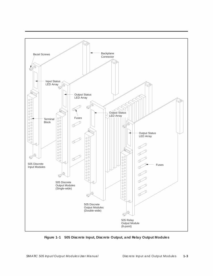
The 505 Discrete Input and Discrete Output modules (see Figure 1-1)contain 8-, 16- or 32- input or output circuits and can accept AC or DCvoltage, depending on the model. (See Appendix A for model numbers andnumber of input or output points.)
Both the input and output circuits are grouped into four commons for eachmodule. (Isolation is provided between each of the four commons. SeeAppendix A for isolation specifications.)
The Discrete Input modules are particularly valuable in areas whereapplications such as limit switches or pushbuttons are needed.
The Discrete AC Output modules are equipped with heavy-duty triacs,without zero cross circuits, to give a faster turn-on response.
The 505 Relay Output Modules (see Figure 1-1) may contain 8-, 16- or 32-output points. (See Appendix A for number of points contained in eachmodel.) These modules are particularly valuable for applications where:
• A “no leakage” output is mandatory in the off-state condition.
• Load currents must be isolated.
• A mixture of voltages must be connected to the same module (forexample, 24 VDC and 24 VAC).
The 16- and 32- point relay modules are equipped with four isolatedcommons, and can switch either AC or DC power at each common. The8-point module is equipped with 8 isolated commons (one for each point),and can switch either AC or DC power at each point. These modules are lesssusceptible than other DC-type modules to inductive load transients whenthe outputs are turned on or off.
The 32- and 16- point modules (PPX:505–4932 and PPX:505–4916) providenormally open (Form-A) contacts, while the 8-point module (PPX:505–4908)provides both normally open and normally closed contacts (Form-C). ThePPX:505–5417 and PPX:505–5518 provide both normally open and normallyclosed contacts (Form-C).
The PPX:505–5518 module provides snubbers on the normally opencontacts. This snubber should be used with inductive loads to extend thecontact life. The snubber is composed of a series 330 Ω resistor and a 0.1 µfcapacitor. If the load requires a “dry contact” relay then the snubber can bedisconnected. To connect the snubber, move the shorting plug associatedwith the output point, to on. For example, for a normally open output 5 thesnubber is controlled by E5. See Figure 3-14 for a typical connection.
DiscreteInput/OutputModules
Relay OutputModules
Discrete Input and Output Modules 1-3SIMATIC 505 Input/Output Modules User Manual
BackplaneConnector
Input StatusLED Array
Output StatusLED Array
505 DiscreteInput Modules
505 DiscreteOutput Modules(Single-wide)
505 DiscreteOutput Modules(Double-wide)
Output StatusLED Array
505 RelayOutput Module(8-point)
Fuses
Fuses
Output StatusLED Array
Bezel Screws
TerminalBlock
Figure 1-1 505 Discrete Input, Discrete Output, and Relay Output Modules
Discrete Input and Output Modules1-4 SIMATIC 505 Input/Output Modules User Manual
Module Descriptions (continued)
The PPX:505–6010 Input Simulator Module simulates discrete inputs to theSeries 505 PLC; PPX:505–6011 Output Simulator Module simulates discreteoutputs from the Series 505 PLC. The modules are designed for use indebugging and troubleshooting.
The modules fit any I/O slot of your Series 505 base. No wiring is necessaryand the modules operate without user-side power.
Each I/O Simulator Module has 32 LEDs on the front bezel. Each LEDrepresents an input or output point. The Input Simulator points areconfigured as X and the Output Simulator points are configured as Y. TheInput Simulator Module also has 17 switches on its front bezel. See page 1-5for details on switch functions.
I/O Simulators
Discrete Input and Output Modules 1-5SIMATIC 505 Input/Output Modules User Manual
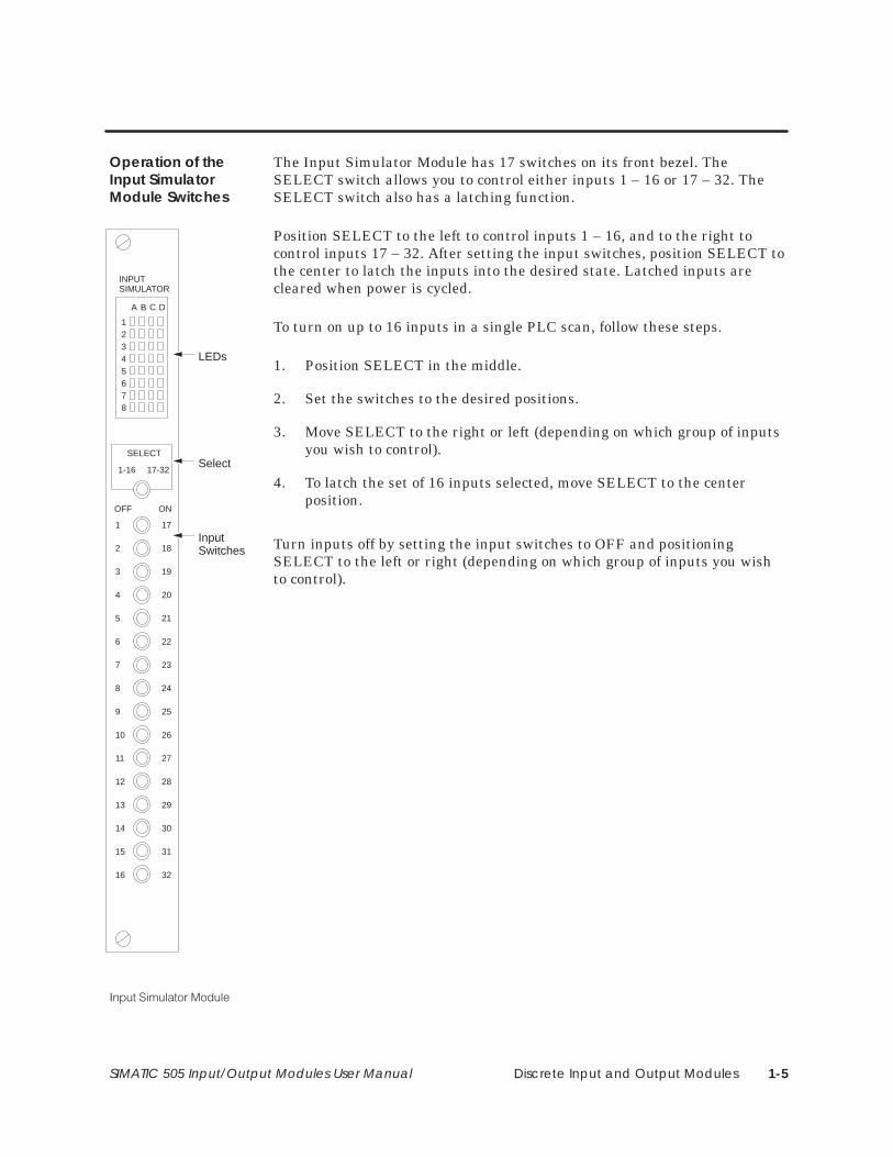
The Input Simulator Module has 17 switches on its front bezel. TheSELECT switch allows you to control either inputs 1 – 16 or 17 – 32. TheSELECT switch also has a latching function.
Position SELECT to the left to control inputs 1 – 16, and to the right tocontrol inputs 17 – 32. After setting the input switches, position SELECT tothe center to latch the inputs into the desired state. Latched inputs arecleared when power is cycled.
To turn on up to 16 inputs in a single PLC scan, follow these steps.
1. Position SELECT in the middle.
2. Set the switches to the desired positions.
3. Move SELECT to the right or left (depending on which group of inputsyou wish to control).
4. To latch the set of 16 inputs selected, move SELECT to the centerposition.
Turn inputs off by setting the input switches to OFF and positioningSELECT to the left or right (depending on which group of inputs you wishto control).
Operation of theInput SimulatorModule Switches
INPUTSIMULATOR
12345678
A B C D
SELECT
1-16 17-32
OFF ON
1
2
3
4
5
6
7
8
9
10
11
12
13
14
15
16
17
18
19
20
21
22
23
24
25
26
27
28
29
30
31
32
LEDs
Select
InputSwitches
Discrete Input and Output Modules1-6 SIMATIC 505 Input/Output Modules User Manual
1.2 Power Sources
The 505 Discrete Output and Relay modules must receive both user- andbase-supplied power to operate correctly. Refer to your controller systemmanual for instructions on wiring the base and power supply.
The outputs in the Discrete Output and normally open outputs inthe Discrete Relay Output modules will be off as long as the powerto the base is off, even if the user power is on.
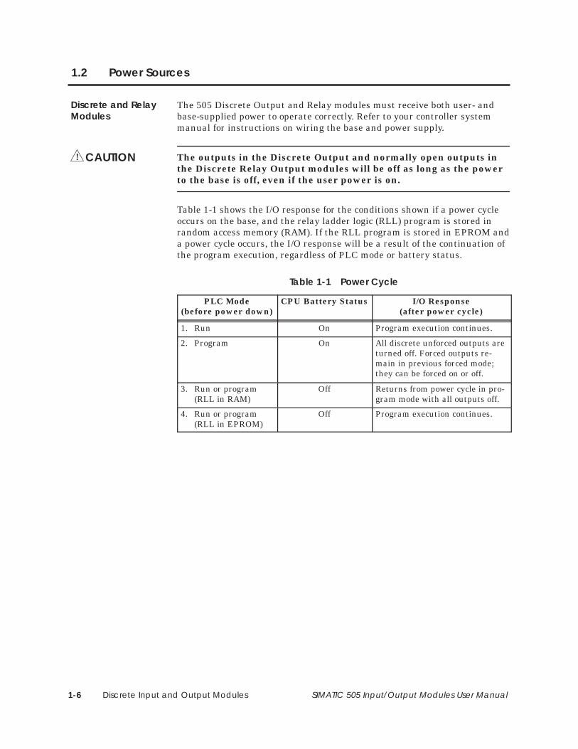
Table 1-1 shows the I/O response for the conditions shown if a power cycleoccurs on the base, and the relay ladder logic (RLL) program is stored inrandom access memory (RAM). If the RLL program is stored in EPROM anda power cycle occurs, the I/O response will be a result of the continuation ofthe program execution, regardless of PLC mode or battery status.
Table 1-1 Power Cycle
PLC Mode(before power down)
CPU Battery Status I/O Response(after power cycle)
1. Run On Program execution continues.
2. Program On All discrete unforced outputs areturned off. Forced outputs re-main in previous forced mode;they can be forced on or off.
3. Run or program(RLL in RAM)
Off Returns from power cycle in pro-gram mode with all outputs off.
4. Run or program(RLL in EPROM)
Off Program execution continues.
Discrete and RelayModules
CAUTION!
Discrete Input and Output Modules 1-7SIMATIC 505 Input/Output Modules User Manual
1.3 LED Arrays
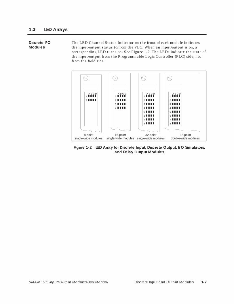
The LED Channel Status Indicator on the front of each module indicatesthe input/output status to/from the PLC. When an input/output is on, acorresponding LED turns on. See Figure 1-2. The LEDs indicate the state ofthe input/output from the Programmable Logic Controller (PLC) side, notfrom the field side.
A B C D1
2
A B C D1
2
3
4
A B C D1
2
3
4
5
6
7
8
A B C D1
2
3
4
5
6
7
8
8-pointsingle-wide modules
16-pointsingle-wide modules
32-pointsingle-wide modules
32-pointdouble-wide modules
Figure 1-2 LED Array for Discrete Input, Discrete Output, I/O Simulators,and Relay Output Modules
Discrete I/OModules
Discrete Input and Output Modules1-8 SIMATIC 505 Input/Output Modules User Manual
1.4 Fuses
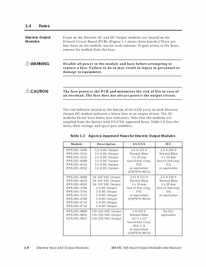
Fuses on the Discrete AC and DC Output modules are located on thePrinted Circuit Board (PCB). (Figure 1-1 shows these boards.) There arefour fuses on the module, one for each common. To gain access to the fuses,remove the module from the base.
Disable all power to the module and base before attempting toreplace a fuse. Failure to do so may result in injury to personnel ordamage to equipment.
The fuse protects the PCB and minimizes the risk of fire in case ofan overload. The fuse does not always protect the output circuit.
The red indicator located at the bottom of the LED array on each DiscreteOutput DC module indicates a blown fuse in an output circuit. The ACmodules do not have blown fuse indicators. Note that the modules aresupplied from the factory with UL/CSA approved fuses. Table 1-2 lists thefuses, their ratings, and spare part numbers.
Table 1-2 Agency-Approved Fuses for Discrete Output Modules
Module Description UL/CSA IEC
PPX:505–3508PPX:505–3516PPX:505–3532PPX:505–4508PPX:505–4516PPX:505–4532
1/2 A DC Output1/2 A DC Output1/2 A DC Output1/2 A DC Output1/2 A DC Output1/2 A DC Output
3.0 A 125 VNormal Blow
5 x 20 mmSan-O-Ind. Corp.
TSCor equivalent
(2587679–8012)
2.5 A 250 VNormal Blow
5 x 20 mmSan-O–Ind.corp.
EQor equivalent
PPX:505–4608PPX:505–4616PPX:505–4632PPX:505–3708PPX:505–3716PPX:505–3732PPX:505–4708PPX:505–4716PPX:505–4732
24–110 VAC Output24–110 VAC Output24–110 VAC Output
2 A DC Output2 A DC Output2 A DC Output2 A DC Output2 A DC Output2 A DC Output
3.15 A 125 VNormal Blow
5 x 20 mmSan-O-Ind. Corp.
TSCor equivalent
(2587679–8014)
2.5 A 250 VNormal Blow
5 x 20 mmSan-O–Ind.corp.
EQor equivalent
PPX:505–4808PPX:505–4816PPX:505–4832
110–220 VAC Output110–220 VAC Output110–220 VAC Output
5 A 250 VNormal Blow.25” x 1.25”
San-O-Ind. Corp.SS2–5 A
or equivalent(2587679–8013)
No IECequivalent
Discrete OutputModules
WARNING!
CAUTION!
Discrete Input and Output Modules 1-9SIMATIC 505 Input/Output Modules User Manual
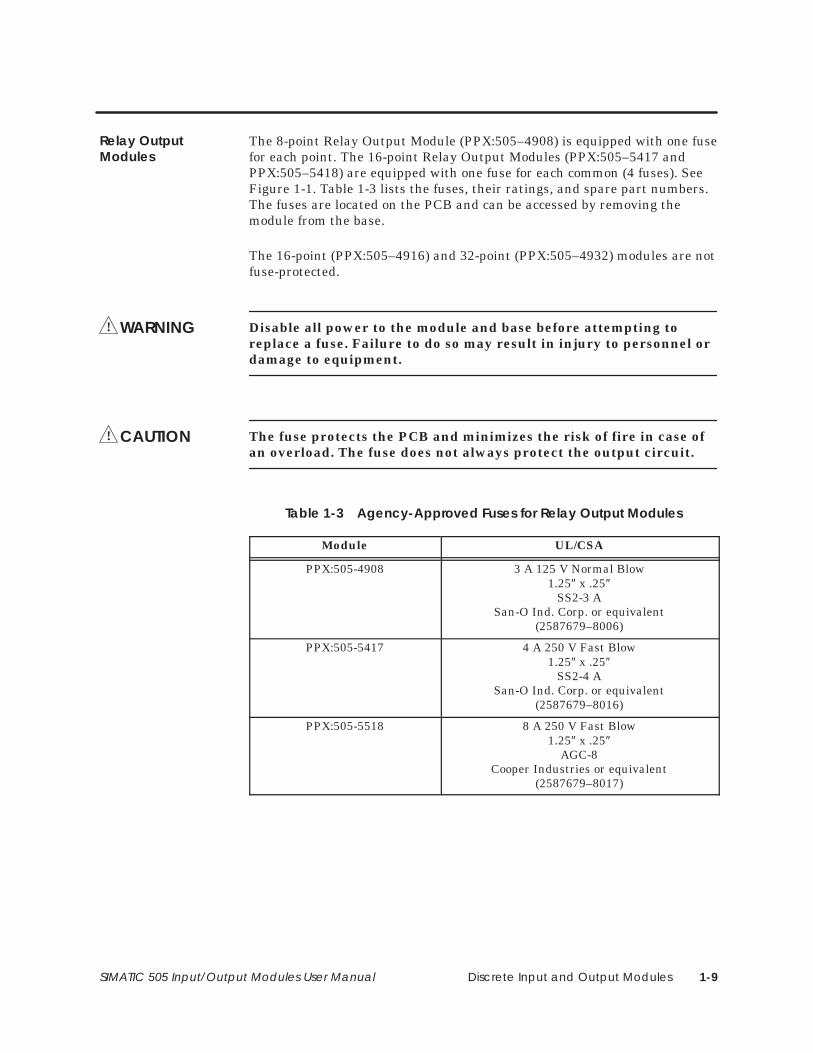
The 8-point Relay Output Module (PPX:505–4908) is equipped with one fusefor each point. The 16-point Relay Output Modules (PPX:505–5417 andPPX:505–5418) are equipped with one fuse for each common (4 fuses). SeeFigure 1-1. Table 1-3 lists the fuses, their ratings, and spare part numbers.The fuses are located on the PCB and can be accessed by removing themodule from the base.
The 16-point (PPX:505–4916) and 32-point (PPX:505–4932) modules are notfuse-protected.
Disable all power to the module and base before attempting toreplace a fuse. Failure to do so may result in injury to personnel ordamage to equipment.
The fuse protects the PCB and minimizes the risk of fire in case ofan overload. The fuse does not always protect the output circuit.
Table 1-3 Agency-Approved Fuses for Relay Output Modules
Module UL/CSA
PPX:505-4908 3 A 125 V Normal Blow1.25″ x .25″
SS2-3 ASan-O Ind. Corp. or equivalent
(2587679–8006)
PPX:505-5417 4 A 250 V Fast Blow1.25″ x .25″
SS2-4 ASan-O Ind. Corp. or equivalent
(2587679–8016)
PPX:505-5518 8 A 250 V Fast Blow1.25″ x .25″
AGC-8Cooper Industries or equivalent
(2587679–8017)
Relay OutputModules
WARNING!
CAUTION!
Word Input and Output Modules 2-1SIMATIC 505 Input/Output Modules User Manual
Chapter 2
Word Input and Output Modules
2.1 Module Descriptions 2-2. . . . . . . . . . . . . . . . . . . . . . . . . . . . . . . . . . . . . . . . . . . . . . . . . . . . . . . . . . . . Word Input Module 2-2. . . . . . . . . . . . . . . . . . . . . . . . . . . . . . . . . . . . . . . . . . . . . . . . . . . . . . . . . . . . . Word Output Module 2-3. . . . . . . . . . . . . . . . . . . . . . . . . . . . . . . . . . . . . . . . . . . . . . . . . . . . . . . . . . . Data Word Format 2-4. . . . . . . . . . . . . . . . . . . . . . . . . . . . . . . . . . . . . . . . . . . . . . . . . . . . . . . . . . . . . .
2.2 Power Sources 2-5. . . . . . . . . . . . . . . . . . . . . . . . . . . . . . . . . . . . . . . . . . . . . . . . . . . . . . . . . . . . . . . . . . Power Supplies 2-5. . . . . . . . . . . . . . . . . . . . . . . . . . . . . . . . . . . . . . . . . . . . . . . . . . . . . . . . . . . . . . . . . Early Power Failure 2-5. . . . . . . . . . . . . . . . . . . . . . . . . . . . . . . . . . . . . . . . . . . . . . . . . . . . . . . . . . . . . .
2.3 LED Arrays 2-6. . . . . . . . . . . . . . . . . . . . . . . . . . . . . . . . . . . . . . . . . . . . . . . . . . . . . . . . . . . . . . . . . . . . . . LED Status Indicators 2-6. . . . . . . . . . . . . . . . . . . . . . . . . . . . . . . . . . . . . . . . . . . . . . . . . . . . . . . . . . . .
2.4 Fuses 2-7. . . . . . . . . . . . . . . . . . . . . . . . . . . . . . . . . . . . . . . . . . . . . . . . . . . . . . . . . . . . . . . . . . . . . . . . . . . Fuse Locations 2-7. . . . . . . . . . . . . . . . . . . . . . . . . . . . . . . . . . . . . . . . . . . . . . . . . . . . . . . . . . . . . . . . . .
2.5 Timing Characteristics 2-8. . . . . . . . . . . . . . . . . . . . . . . . . . . . . . . . . . . . . . . . . . . . . . . . . . . . . . . . . . . Input Scan 2-8. . . . . . . . . . . . . . . . . . . . . . . . . . . . . . . . . . . . . . . . . . . . . . . . . . . . . . . . . . . . . . . . . . . . . Output Scan 2-8. . . . . . . . . . . . . . . . . . . . . . . . . . . . . . . . . . . . . . . . . . . . . . . . . . . . . . . . . . . . . . . . . . .
2.6 Jumper Options 2-9. . . . . . . . . . . . . . . . . . . . . . . . . . . . . . . . . . . . . . . . . . . . . . . . . . . . . . . . . . . . . . . . . Selecting Options 2-9. . . . . . . . . . . . . . . . . . . . . . . . . . . . . . . . . . . . . . . . . . . . . . . . . . . . . . . . . . . . . . . Word Input Data Active Level 2-9. . . . . . . . . . . . . . . . . . . . . . . . . . . . . . . . . . . . . . . . . . . . . . . . . . . Word Output Data Active Level 2-10. . . . . . . . . . . . . . . . . . . . . . . . . . . . . . . . . . . . . . . . . . . . . . . . . Word Input Strobe Active Level 2-11. . . . . . . . . . . . . . . . . . . . . . . . . . . . . . . . . . . . . . . . . . . . . . . . . . Word Output Strobe Active Level 2-11. . . . . . . . . . . . . . . . . . . . . . . . . . . . . . . . . . . . . . . . . . . . . . . . Word Input Internal Resistance 2-12. . . . . . . . . . . . . . . . . . . . . . . . . . . . . . . . . . . . . . . . . . . . . . . . . . Word Input Drive Capabilities 2-12. . . . . . . . . . . . . . . . . . . . . . . . . . . . . . . . . . . . . . . . . . . . . . . . . . . . Word Output Drive Capabilities 2-13. . . . . . . . . . . . . . . . . . . . . . . . . . . . . . . . . . . . . . . . . . . . . . . . . . Word Input Strobe Source 2-13. . . . . . . . . . . . . . . . . . . . . . . . . . . . . . . . . . . . . . . . . . . . . . . . . . . . . . . Word Output Channel Operation 2-15. . . . . . . . . . . . . . . . . . . . . . . . . . . . . . . . . . . . . . . . . . . . . . . . Eight- and Single-Channel Modes 2-16. . . . . . . . . . . . . . . . . . . . . . . . . . . . . . . . . . . . . . . . . . . . . . . .
Word Input and Output Modules2-2 SIMATIC 505 Input/Output Modules User Manual
2.1 Module Descriptions
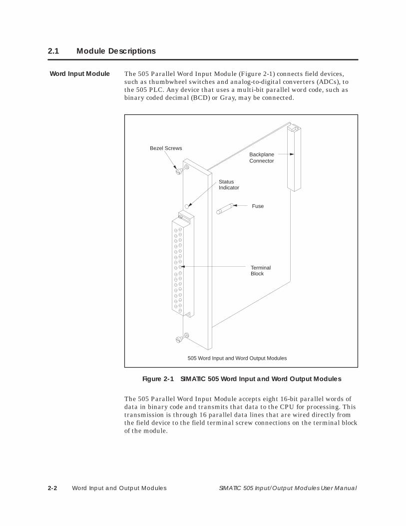
The 505 Parallel Word Input Module (Figure 2-1) connects field devices,such as thumbwheel switches and analog-to-digital converters (ADCs), tothe 505 PLC. Any device that uses a multi-bit parallel word code, such asbinary coded decimal (BCD) or Gray, may be connected.
TerminalBlock
505 Word Input and Word Output Modules
StatusIndicator
BackplaneConnector
Fuse
Bezel Screws
Figure 2-1 SIMATIC 505 Word Input and Word Output Modules
The 505 Parallel Word Input Module accepts eight 16-bit parallel words ofdata in binary code and transmits that data to the CPU for processing. Thistransmission is through 16 parallel data lines that are wired directly fromthe field device to the field terminal screw connections on the terminal blockof the module.
Word Input Module
Word Input and Output Modules 2-3SIMATIC 505 Input/Output Modules User Manual
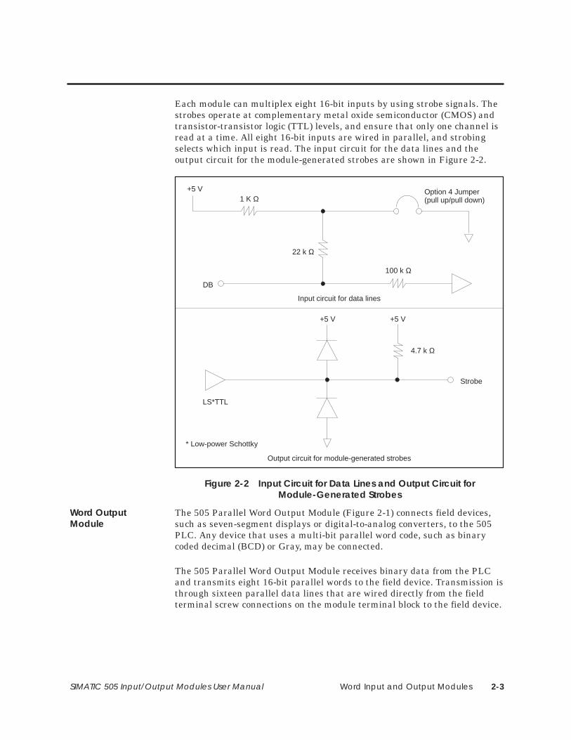
Each module can multiplex eight 16-bit inputs by using strobe signals. Thestrobes operate at complementary metal oxide semiconductor (CMOS) andtransistor-transistor logic (TTL) levels, and ensure that only one channel isread at a time. All eight 16-bit inputs are wired in parallel, and strobingselects which input is read. The input circuit for the data lines and theoutput circuit for the module-generated strobes are shown in Figure 2-2.
Input circuit for data lines
+5 V1 K Ω
22 k Ω
100 k Ω
DB
Option 4 Jumper(pull up/pull down)
Output circuit for module-generated strobes
Strobe
LS*TTL
+5 V
4.7 k Ω
+5 V
* Low-power Schottky
Figure 2-2 Input Circuit for Data Lines and Output Circuit forModule-Generated Strobes
The 505 Parallel Word Output Module (Figure 2-1) connects field devices,such as seven-segment displays or digital-to-analog converters, to the 505PLC. Any device that uses a multi-bit parallel word code, such as binarycoded decimal (BCD) or Gray, may be connected.
The 505 Parallel Word Output Module receives binary data from the PLCand transmits eight 16-bit parallel words to the field device. Transmission isthrough sixteen parallel data lines that are wired directly from the fieldterminal screw connections on the module terminal block to the field device.
Word OutputModule
Word Input and Output Modules2-4 SIMATIC 505 Input/Output Modules User Manual
Module Descriptions (continued)
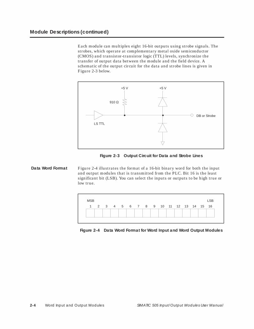
Each module can multiplex eight 16-bit outputs using strobe signals. Thestrobes, which operate at complementary metal oxide semiconductor(CMOS) and transistor-transistor logic (TTL) levels, synchronize thetransfer of output data between the module and the field device. Aschematic of the output circuit for the data and strobe lines is given inFigure 2-3 below.
DB or Strobe
+5 V
910 Ω
+5 V
LS TTL
Figure 2-3 Output Circuit for Data and Strobe Lines
Figure 2-4 illustrates the format of a 16-bit binary word for both the inputand output modules that is transmitted from the PLC. Bit 16 is the leastsignificant bit (LSB). You can select the inputs or outputs to be high true orlow true.
1 2 3 4 5 6 7 8 9 10 11 12 13 14 15 16
MSB LSB
Figure 2-4 Data Word Format for Word Input and Word Output Modules
Data Word Format
Word Input and Output Modules 2-5SIMATIC 505 Input/Output Modules User Manual
2.2 Power Sources
The Word Input and Word Output modules have been designed to use alow-cost, user-provided power supply. Each module requires only a singlevoltage source of 20-30 VDC: 0.25 A for the Word Input, and 0.35 A for theWord Output. The user power supply must have a ripple less than 0.4 volts.Power supply connections are shown in Figure 3–15.
NOTE: A UL Class 2 power supply must be used to ensure UL listingcompliance for this module.
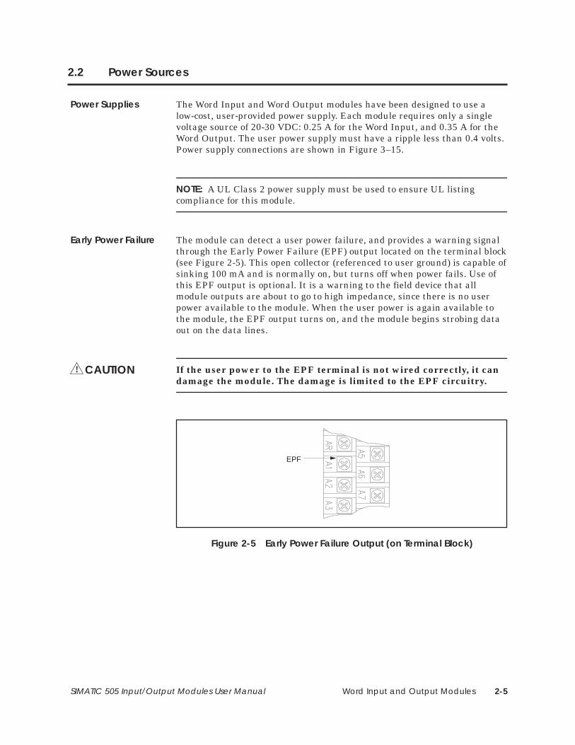
The module can detect a user power failure, and provides a warning signalthrough the Early Power Failure (EPF) output located on the terminal block(see Figure 2-5). This open collector (referenced to user ground) is capable ofsinking 100 mA and is normally on, but turns off when power fails. Use ofthis EPF output is optional. It is a warning to the field device that allmodule outputs are about to go to high impedance, since there is no userpower available to the module. When the user power is again available tothe module, the EPF output turns on, and the module begins strobing dataout on the data lines.
If the user power to the EPF terminal is not wired correctly, it candamage the module. The damage is limited to the EPF circuitry.
EPF
Figure 2-5 Early Power Failure Output (on Terminal Block)
Power Supplies
Early Power Failure
CAUTION!
Word Input and Output Modules2-6 SIMATIC 505 Input/Output Modules User Manual
2.3 LED Arrays
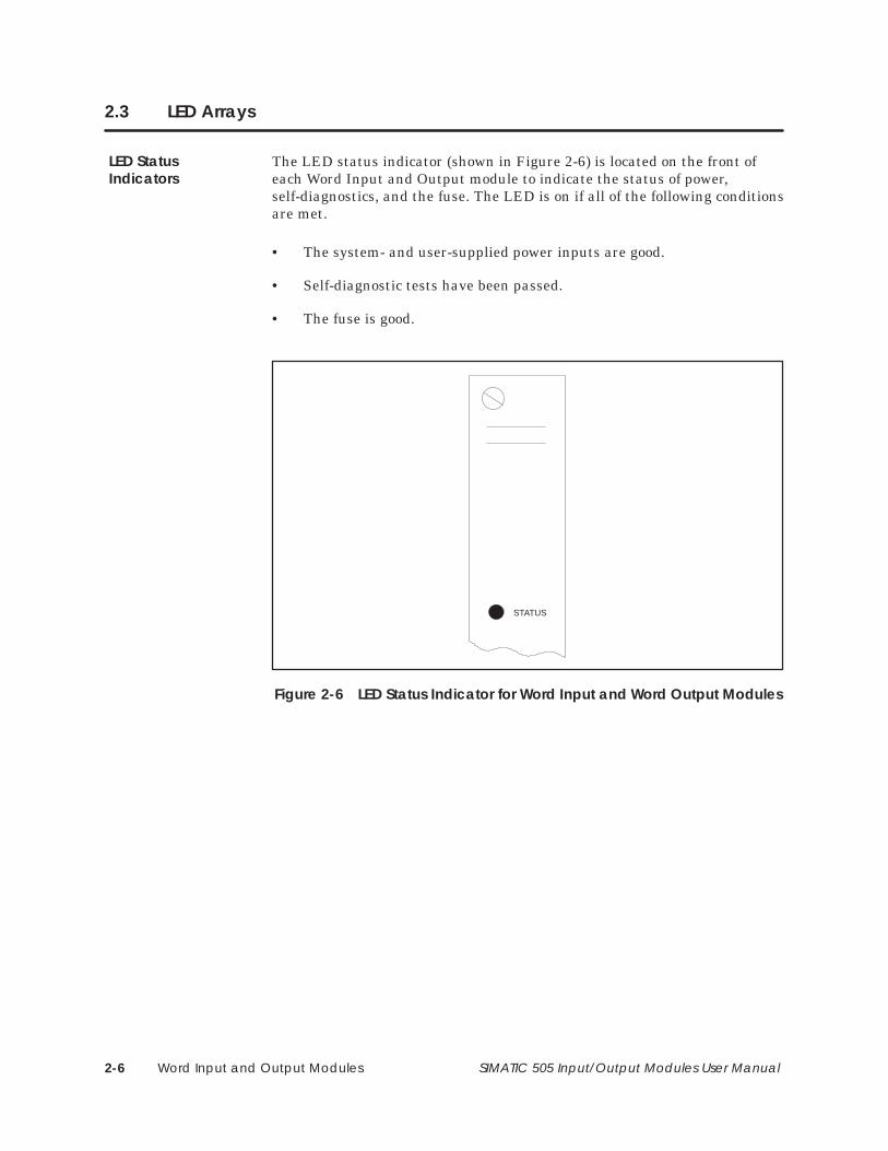
The LED status indicator (shown in Figure 2-6) is located on the front ofeach Word Input and Output module to indicate the status of power,self-diagnostics, and the fuse. The LED is on if all of the following conditionsare met.
• The system- and user-supplied power inputs are good.
• Self-diagnostic tests have been passed.
• The fuse is good.
STATUS
Figure 2-6 LED Status Indicator for Word Input and Word Output Modules
LED StatusIndicators
Word Input and Output Modules 2-7SIMATIC 505 Input/Output Modules User Manual
2.4 Fuses
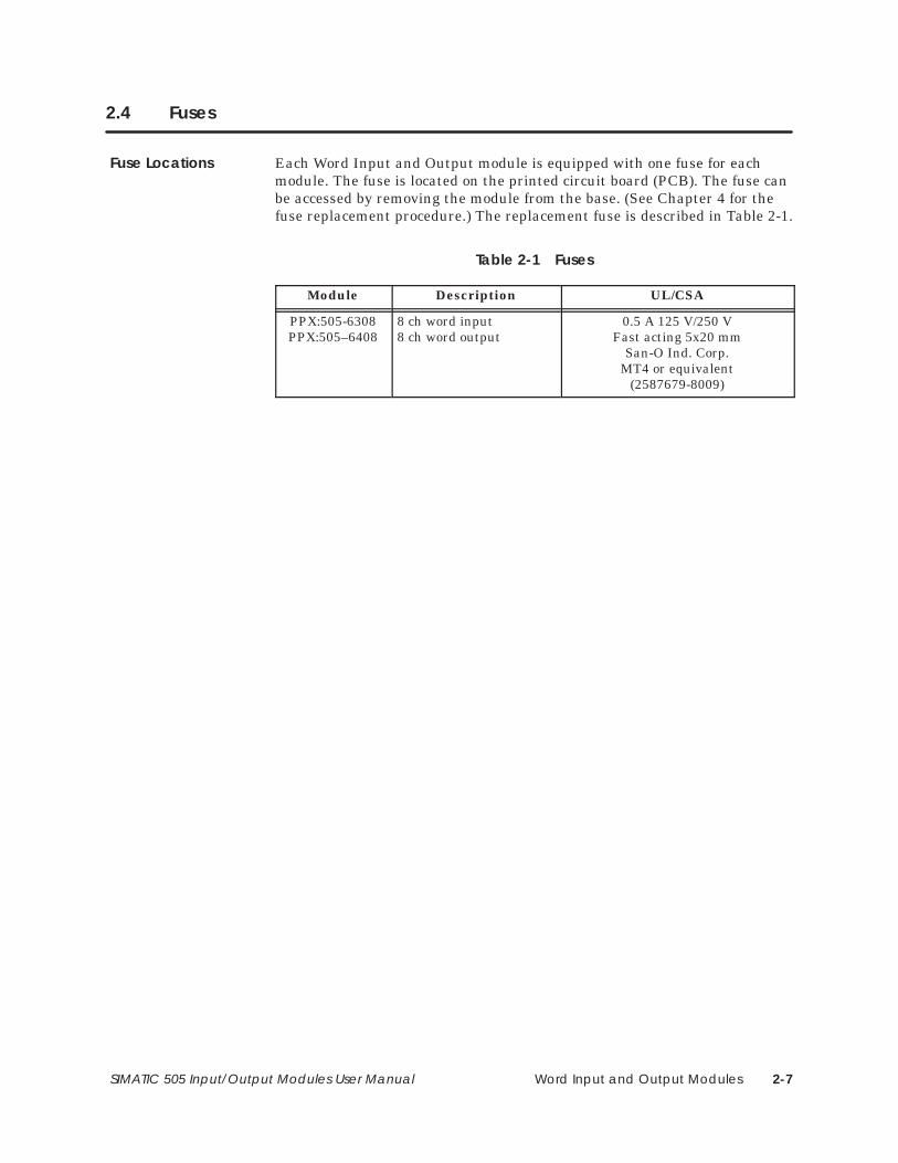
Each Word Input and Output module is equipped with one fuse for eachmodule. The fuse is located on the printed circuit board (PCB). The fuse canbe accessed by removing the module from the base. (See Chapter 4 for thefuse replacement procedure.) The replacement fuse is described in Table 2-1.
Table 2-1 Fuses
Module Description UL/CSA
PPX:505-6308PPX:505–6408
8 ch word input8 ch word output
0.5 A 125 V/250 VFast acting 5x20 mm
San-O Ind. Corp.MT4 or equivalent
(2587679-8009)
Fuse Locations
Word Input and Output Modules2-8 SIMATIC 505 Input/Output Modules User Manual
2.5 Timing Characteristics
Both the Word Input and Word Output modules operate asynchronouslywith the PLC; i.e., the scan time and PLC scan time are not synchronized.
The input module scan consists of converting all input channels, and storingthe conversion data in the buffer memory. The channels are converted oneat a time. The update time associated with the eight channels is less than 8ms. The input module does not update its buffer memory when the PLC isaccessing the module. For example, if the module has just updated channel3 when the PLC accesses the module, then channel 3 contains the mostrecent data, then channel 2, followed by channels 1, 8, 7, 6, 5, and 4.
The output module scan consists of accepting all output data words, storingthe data in buffer memory, and transferring the data to the output memory.The channels are transferred one at a time from buffer memory to outputmemory. The update time associated with the eight channels is less than 16 ms. The module does not update its output memory when the PLC isaccessing the module. For example, if the module has just updated theoutput memory for channel 3 when the PLC accesses the module, then thedata words for channels 1 through 3 would have been transmitted withvalues from the previous module scan. Channels 4 through 8 aretransmitted with data words from the next module scan, unless the PLCaccesses the module again before the remaining data words are transmitted.
Input Scan
Output Scan
Word Input and Output Modules 2-9SIMATIC 505 Input/Output Modules User Manual
2.6 Jumper Options
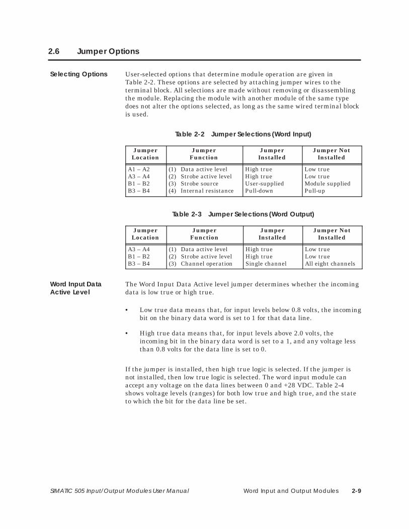
User-selected options that determine module operation are given inTable 2-2. These options are selected by attaching jumper wires to theterminal block. All selections are made without removing or disassemblingthe module. Replacing the module with another module of the same typedoes not alter the options selected, as long as the same wired terminal blockis used.
Table 2-2 Jumper Selections (Word Input)
JumperLocation
JumperFunction
JumperInstalled
Jumper NotInstalled
A1 – A2A3 – A4B1 – B2B3 – B4
(1) Data active level(2) Strobe active level(3) Strobe source(4) Internal resistance
High trueHigh trueUser-suppliedPull-down
Low trueLow trueModule suppliedPull-up
Table 2-3 Jumper Selections (Word Output)
JumperLocation
JumperFunction
JumperInstalled
Jumper NotInstalled
A3 – A4B1 – B2B3 – B4
(1) Data active level(2) Strobe active level(3) Channel operation
High trueHigh trueSingle channel
Low trueLow trueAll eight channels
The Word Input Data Active level jumper determines whether the incomingdata is low true or high true.
• Low true data means that, for input levels below 0.8 volts, the incomingbit on the binary data word is set to 1 for that data line.
• High true data means that, for input levels above 2.0 volts, theincoming bit in the binary data word is set to a 1, and any voltage lessthan 0.8 volts for the data line is set to 0.
If the jumper is installed, then high true logic is selected. If the jumper isnot installed, then low true logic is selected. The word input module canaccept any voltage on the data lines between 0 and +28 VDC. Table 2-4shows voltage levels (ranges) for both low true and high true, and the stateto which the bit for the data line be set.
Selecting Options
Word Input DataActive Level
Word Input and Output Modules2-10 SIMATIC 505 Input/Output Modules User Manual
Jumper Options (continued)
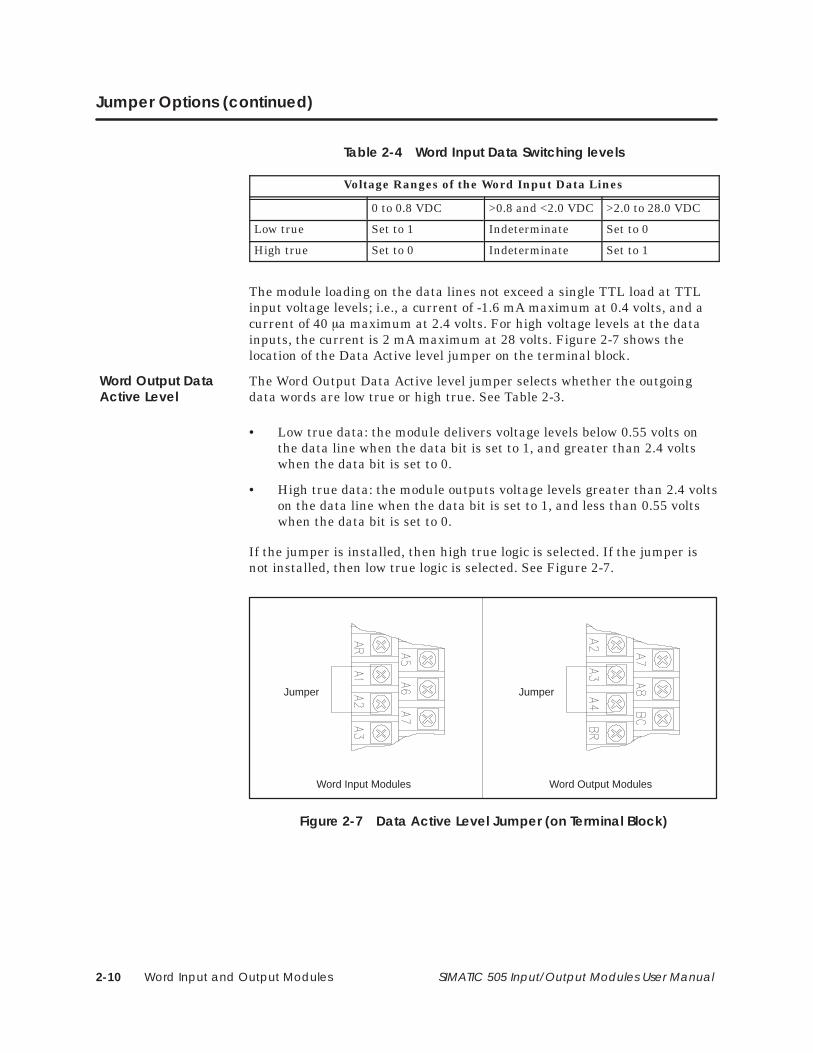
Table 2-4 Word Input Data Switching levels
Voltage Ranges of the Word Input Data Lines
0 to 0.8 VDC >0.8 and <2.0 VDC >2.0 to 28.0 VDC
Low true Set to 1 Indeterminate Set to 0
High true Set to 0 Indeterminate Set to 1
The module loading on the data lines not exceed a single TTL load at TTLinput voltage levels; i.e., a current of -1.6 mA maximum at 0.4 volts, and acurrent of 40 a maximum at 2.4 volts. For high voltage levels at the datainputs, the current is 2 mA maximum at 28 volts. Figure 2-7 shows thelocation of the Data Active level jumper on the terminal block.
The Word Output Data Active level jumper selects whether the outgoingdata words are low true or high true. See Table 2-3.
• Low true data: the module delivers voltage levels below 0.55 volts onthe data line when the data bit is set to 1, and greater than 2.4 voltswhen the data bit is set to 0.
• High true data: the module outputs voltage levels greater than 2.4 voltson the data line when the data bit is set to 1, and less than 0.55 voltswhen the data bit is set to 0.
If the jumper is installed, then high true logic is selected. If the jumper isnot installed, then low true logic is selected. See Figure 2-7.
Word Output Modules
JumperJumper
Word Input Modules
Figure 2-7 Data Active Level Jumper (on Terminal Block)
Word Output DataActive Level
Word Input and Output Modules 2-11SIMATIC 505 Input/Output Modules User Manual
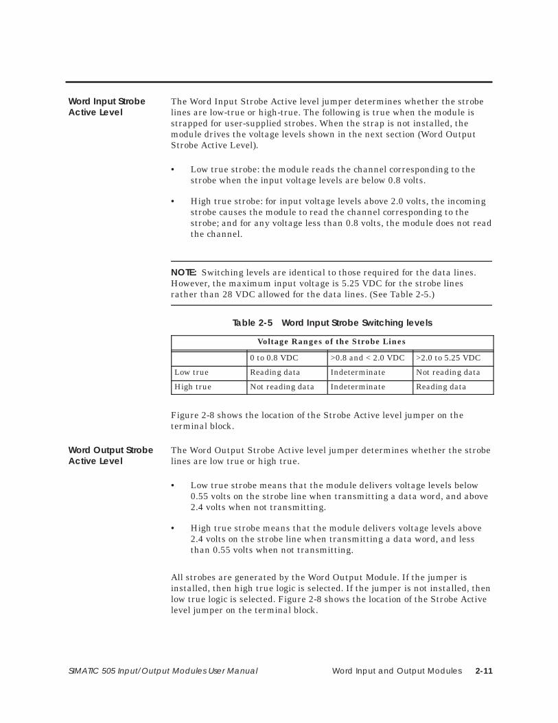
The Word Input Strobe Active level jumper determines whether the strobelines are low-true or high-true. The following is true when the module isstrapped for user-supplied strobes. When the strap is not installed, themodule drives the voltage levels shown in the next section (Word OutputStrobe Active Level).
• Low true strobe: the module reads the channel corresponding to thestrobe when the input voltage levels are below 0.8 volts.
• High true strobe: for input voltage levels above 2.0 volts, the incomingstrobe causes the module to read the channel corresponding to thestrobe; and for any voltage less than 0.8 volts, the module does not readthe channel.
NOTE: Switching levels are identical to those required for the data lines.However, the maximum input voltage is 5.25 VDC for the strobe linesrather than 28 VDC allowed for the data lines. (See Table 2-5.)
Table 2-5 Word Input Strobe Switching levels
Voltage Ranges of the Strobe Lines
0 to 0.8 VDC >0.8 and < 2.0 VDC >2.0 to 5.25 VDC
Low true Reading data Indeterminate Not reading data
High true Not reading data Indeterminate Reading data
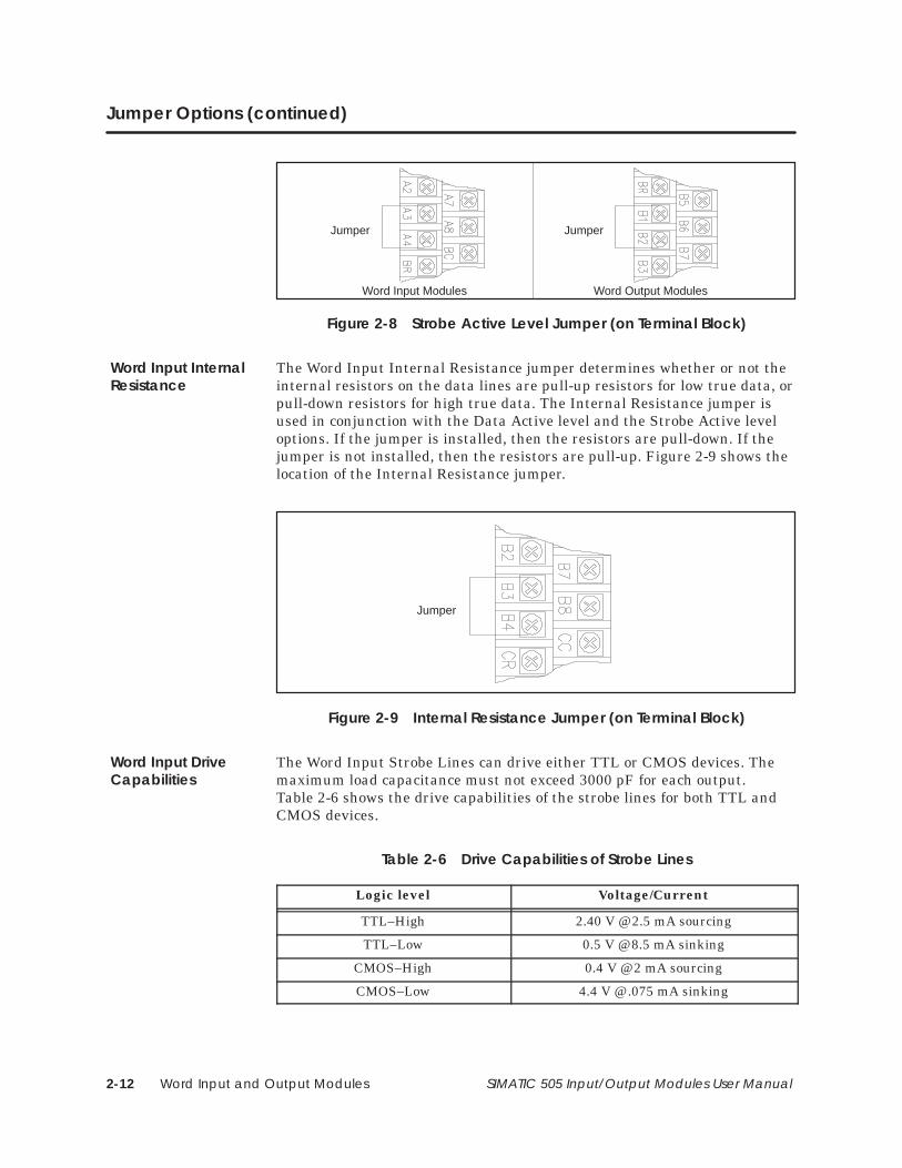
Figure 2-8 shows the location of the Strobe Active level jumper on theterminal block.
The Word Output Strobe Active level jumper determines whether the strobelines are low true or high true.
• Low true strobe means that the module delivers voltage levels below0.55 volts on the strobe line when transmitting a data word, and above2.4 volts when not transmitting.
• High true strobe means that the module delivers voltage levels above2.4 volts on the strobe line when transmitting a data word, and lessthan 0.55 volts when not transmitting.
All strobes are generated by the Word Output Module. If the jumper isinstalled, then high true logic is selected. If the jumper is not installed, thenlow true logic is selected. Figure 2-8 shows the location of the Strobe Activelevel jumper on the terminal block.
Word Input StrobeActive Level
Word Output StrobeActive Level
Word Input and Output Modules2-12 SIMATIC 505 Input/Output Modules User Manual
Jumper Options (continued)
Word Input Modules Word Output Modules
Jumper Jumper
Figure 2-8 Strobe Active Level Jumper (on Terminal Block)
The Word Input Internal Resistance jumper determines whether or not theinternal resistors on the data lines are pull-up resistors for low true data, orpull-down resistors for high true data. The Internal Resistance jumper isused in conjunction with the Data Active level and the Strobe Active leveloptions. If the jumper is installed, then the resistors are pull-down. If thejumper is not installed, then the resistors are pull-up. Figure 2-9 shows thelocation of the Internal Resistance jumper.
Jumper
Figure 2-9 Internal Resistance Jumper (on Terminal Block)
The Word Input Strobe Lines can drive either TTL or CMOS devices. Themaximum load capacitance must not exceed 3000 pF for each output.Table 2-6 shows the drive capabilities of the strobe lines for both TTL andCMOS devices.
Table 2-6 Drive Capabilities of Strobe Lines
Logic level Voltage/Current
TTL–High 2.40 V @ 2.5 mA sourcing
TTL–Low 0.5 V @ 8.5 mA sinking
CMOS–High 0.4 V @ 2 mA sourcing
CMOS–Low 4.4 V @ .075 mA sinking
Word Input InternalResistance
Word Input DriveCapabilities
Word Input and Output Modules 2-13SIMATIC 505 Input/Output Modules User Manual
The Word Output Data/Strobe Lines can drive either TTL or CMOS devices.The maximum load capacitance must not exceed 3000 pF for each output.Table 2-7 shows the drive capabilities of the data and strobe lines for bothTTL and CMOS devices.
Table 2-7 Drive Capabilities of Data/Strobe Lines
Logic level Voltage/Current
TTL–High 2.40 V @ 4.5 mA sourcing
TTL–Low 0.55 V @ 30 mA sinking
CMOS–High 4.40 V @ 0.35 mA sourcing
CMOS–Low 0.4 V @ 3.5 mA sinking
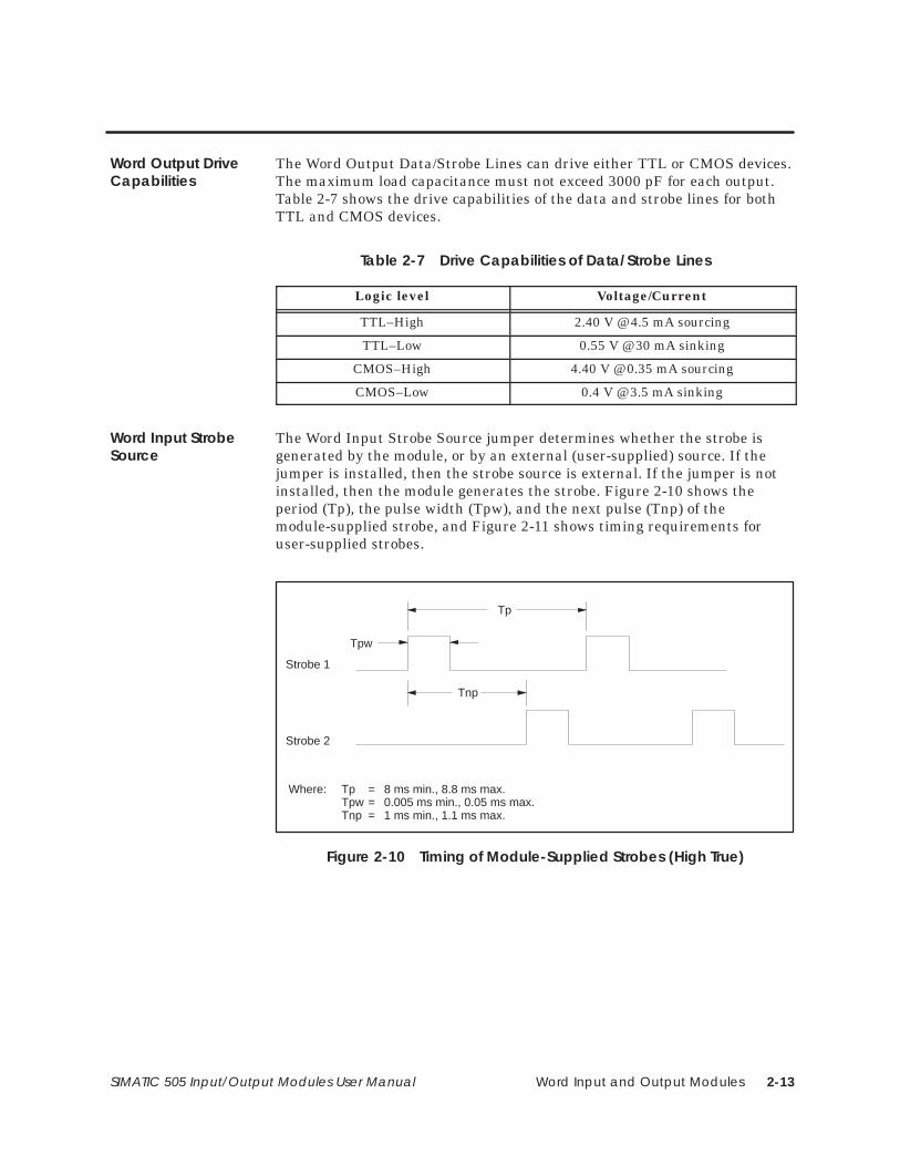
The Word Input Strobe Source jumper determines whether the strobe isgenerated by the module, or by an external (user-supplied) source. If thejumper is installed, then the strobe source is external. If the jumper is notinstalled, then the module generates the strobe. Figure 2-10 shows theperiod (Tp), the pulse width (Tpw), and the next pulse (Tnp) of themodule-supplied strobe, and Figure 2-11 shows timing requirements foruser-supplied strobes.
Tnp
Strobe 1
Tp
Tpw
Strobe 2
Where: Tp = 8 ms min., 8.8 ms max.Tpw = 0.005 ms min., 0.05 ms max.Tnp = 1 ms min., 1.1 ms max.
Figure 2-10 Timing of Module-Supplied Strobes (High True)
Word Output DriveCapabilities
Word Input StrobeSource
Word Input and Output Modules2-14 SIMATIC 505 Input/Output Modules User Manual
Jumper Options (continued)
Tps
Strobe 1
Tp
Tpw
Strobe 2
Where: Tp = 8 ms min., No max.Tpw = 0.002 ms min., No max.Tps = 0.998 ms min., No max.
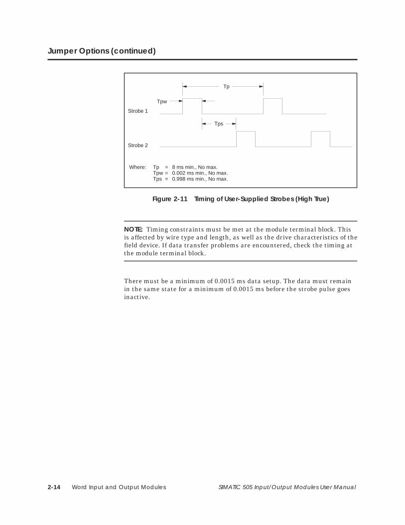
Figure 2-11 Timing of User-Supplied Strobes (High True)
NOTE: Timing constraints must be met at the module terminal block. Thisis affected by wire type and length, as well as the drive characteristics of thefield device. If data transfer problems are encountered, check the timing atthe module terminal block.
There must be a minimum of 0.0015 ms data setup. The data must remainin the same state for a minimum of 0.0015 ms before the strobe pulse goesinactive.
Word Input and Output Modules 2-15SIMATIC 505 Input/Output Modules User Manual
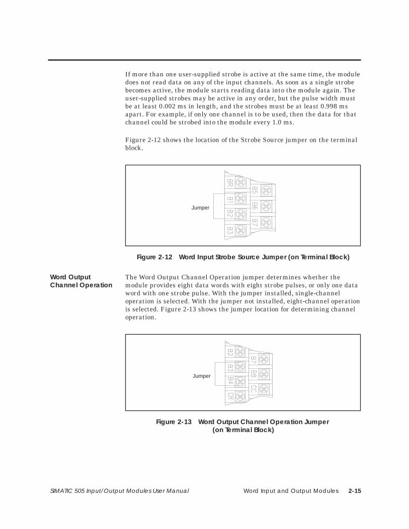
If more than one user-supplied strobe is active at the same time, the moduledoes not read data on any of the input channels. As soon as a single strobebecomes active, the module starts reading data into the module again. Theuser-supplied strobes may be active in any order, but the pulse width mustbe at least 0.002 ms in length, and the strobes must be at least 0.998 msapart. For example, if only one channel is to be used, then the data for thatchannel could be strobed into the module every 1.0 ms.
Figure 2-12 shows the location of the Strobe Source jumper on the terminalblock.
Jumper
Figure 2-12 Word Input Strobe Source Jumper (on Terminal Block)
The Word Output Channel Operation jumper determines whether themodule provides eight data words with eight strobe pulses, or only one dataword with one strobe pulse. With the jumper installed, single-channeloperation is selected. With the jumper not installed, eight-channel operationis selected. Figure 2-13 shows the jumper location for determining channeloperation.
Jumper
Figure 2-13 Word Output Channel Operation Jumper (on Terminal Block)
Word OutputChannel Operation
Word Input and Output Modules2-16 SIMATIC 505 Input/Output Modules User Manual
Jumper Options (continued)
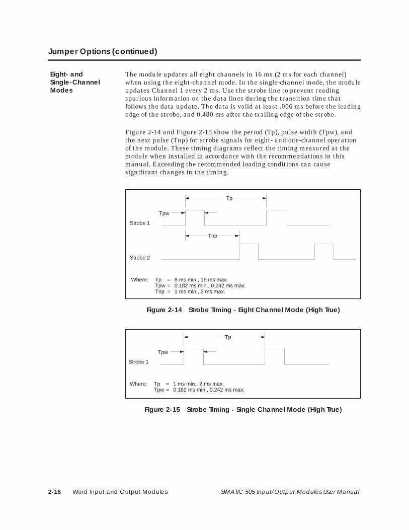
The module updates all eight channels in 16 ms (2 ms for each channel)when using the eight-channel mode. In the single-channel mode, the moduleupdates Channel 1 every 2 ms. Use the strobe line to prevent readingspurious information on the data lines during the transition time thatfollows the data update. The data is valid at least .006 ms before the leadingedge of the strobe, and 0.480 ms after the trailing edge of the strobe.
Figure 2-14 and Figure 2-15 show the period (Tp), pulse width (Tpw), andthe next pulse (Tnp) for strobe signals for eight- and one-channel operationof the module. These timing diagrams reflect the timing measured at themodule when installed in accordance with the recommendations in thismanual. Exceeding the recommended loading conditions can causesignificant changes in the timing.
Tnp
Strobe 1
Tp
Tpw
Strobe 2
Where: Tp = 8 ms min., 16 ms max.Tpw = 0.182 ms min., 0.242 ms max.Tnp = 1 ms min., 2 ms max.
Figure 2-14 Strobe Timing - Eight Channel Mode (High True)
Strobe 1
Tp
Tpw
Where: Tp = 1 ms min., 2 ms max.Tpw = 0.182 ms min., 0.242 ms max.
Figure 2-15 Strobe Timing - Single Channel Mode (High True)
Eight- andSingle-ChannelModes
Installing the Modules 3-1SIMATIC 505 Input/Output Modules User Manual
Chapter 3
Installing the Modules
3.1 Installing the Modules 3-2. . . . . . . . . . . . . . . . . . . . . . . . . . . . . . . . . . . . . . . . . . . . . . . . . . . . . . . . . . . Overview 3-2. . . . . . . . . . . . . . . . . . . . . . . . . . . . . . . . . . . . . . . . . . . . . . . . . . . . . . . . . . . . . . . . . . . . . . . Guidelines 3-2. . . . . . . . . . . . . . . . . . . . . . . . . . . . . . . . . . . . . . . . . . . . . . . . . . . . . . . . . . . . . . . . . . . . . .
3.2 Wiring the Discrete Input and Output Modules 3-3. . . . . . . . . . . . . . . . . . . . . . . . . . . . . . . . . . . . Pin-outs for Discrete Input and Output Modules 3-3. . . . . . . . . . . . . . . . . . . . . . . . . . . . . . . . . . .
3.3 Wiring the Relay Output Modules 3-14. . . . . . . . . . . . . . . . . . . . . . . . . . . . . . . . . . . . . . . . . . . . . . . . Pin-outs for Relay Output Modules 3-14. . . . . . . . . . . . . . . . . . . . . . . . . . . . . . . . . . . . . . . . . . . . . . .
3.4 Wiring the Word Input and Output Modules 3-19. . . . . . . . . . . . . . . . . . . . . . . . . . . . . . . . . . . . . . . Pin-outs for Word Input and Output Modules 3-19. . . . . . . . . . . . . . . . . . . . . . . . . . . . . . . . . . . . . Avoiding Noise 3-21. . . . . . . . . . . . . . . . . . . . . . . . . . . . . . . . . . . . . . . . . . . . . . . . . . . . . . . . . . . . . . . . . Connections and Terminations 3-21. . . . . . . . . . . . . . . . . . . . . . . . . . . . . . . . . . . . . . . . . . . . . . . . . .
3.5 Field Wiring 3-24. . . . . . . . . . . . . . . . . . . . . . . . . . . . . . . . . . . . . . . . . . . . . . . . . . . . . . . . . . . . . . . . . . . . . Wiring Recommendations 3-24. . . . . . . . . . . . . . . . . . . . . . . . . . . . . . . . . . . . . . . . . . . . . . . . . . . . . . . Wiring the Terminal Block 3-25. . . . . . . . . . . . . . . . . . . . . . . . . . . . . . . . . . . . . . . . . . . . . . . . . . . . . . . . Connecting the Terminal Block 3-27. . . . . . . . . . . . . . . . . . . . . . . . . . . . . . . . . . . . . . . . . . . . . . . . . . Typical Connections 3-28. . . . . . . . . . . . . . . . . . . . . . . . . . . . . . . . . . . . . . . . . . . . . . . . . . . . . . . . . . . .
3.6 Connecting Discrete Output Modules 3-37. . . . . . . . . . . . . . . . . . . . . . . . . . . . . . . . . . . . . . . . . . . . AC and DC Output Modules 3-37. . . . . . . . . . . . . . . . . . . . . . . . . . . . . . . . . . . . . . . . . . . . . . . . . . . .
3.7 Loopback Configuration 3-38. . . . . . . . . . . . . . . . . . . . . . . . . . . . . . . . . . . . . . . . . . . . . . . . . . . . . . . . Discrete Input and Output Modules 3-38. . . . . . . . . . . . . . . . . . . . . . . . . . . . . . . . . . . . . . . . . . . . . .
3.8 Configuring I/O 3-39. . . . . . . . . . . . . . . . . . . . . . . . . . . . . . . . . . . . . . . . . . . . . . . . . . . . . . . . . . . . . . . . . Discrete I/O Modules and I/O Simulators 3-39. . . . . . . . . . . . . . . . . . . . . . . . . . . . . . . . . . . . . . . . . Relay Output Modules 3-40. . . . . . . . . . . . . . . . . . . . . . . . . . . . . . . . . . . . . . . . . . . . . . . . . . . . . . . . . . Word Input and Word Output Modules 3-41. . . . . . . . . . . . . . . . . . . . . . . . . . . . . . . . . . . . . . . . . . .
Installing the Modules3-2 SIMATIC 505 Input/Output Modules User Manual
3.1 Installing the Modules
The 505 Discrete Input and Output modules, and Word Input and Outputmodules, may be installed in any available slot (or in two adjacent slots fordouble-wide modules).
To minimize risk of potential shock hazard, turn off power to theI/O base and to any modules installed in the base before insertingor removing a module, or installing a terminal block. Failure to doso may result in potential injury to personnel or damage toequipment.
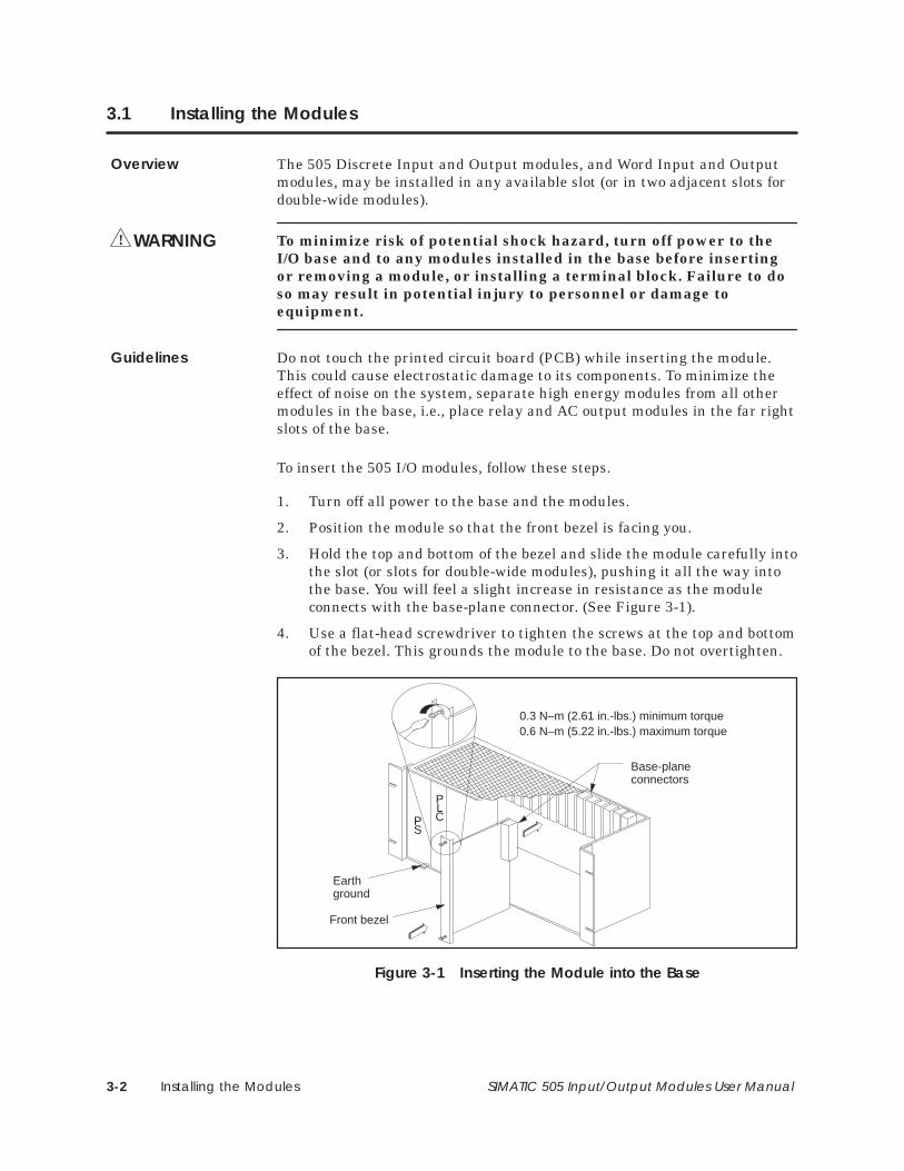
Do not touch the printed circuit board (PCB) while inserting the module.This could cause electrostatic damage to its components. To minimize theeffect of noise on the system, separate high energy modules from all othermodules in the base, i.e., place relay and AC output modules in the far rightslots of the base.
To insert the 505 I/O modules, follow these steps.
1. Turn off all power to the base and the modules.
2. Position the module so that the front bezel is facing you.
3. Hold the top and bottom of the bezel and slide the module carefully intothe slot (or slots for double-wide modules), pushing it all the way intothe base. You will feel a slight increase in resistance as the moduleconnects with the base-plane connector. (See Figure 3-1).
4. Use a flat-head screwdriver to tighten the screws at the top and bottomof the bezel. This grounds the module to the base. Do not overtighten.
Base-planeconnectors
0.3 N–m (2.61 in.-lbs.) minimum torque0.6 N–m (5.22 in.-lbs.) maximum torque
PLCP
S
Earthground
Front bezel
Figure 3-1 Inserting the Module into the Base
Overview
WARNING!
Guidelines
Installing the Modules 3-3SIMATIC 505 Input/Output Modules User Manual
3.2 Wiring the Discrete Input and Output Modules
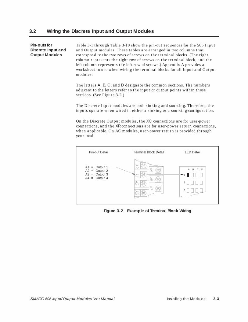
Table 3-1 through Table 3-10 show the pin-out sequences for the 505 Inputand Output modules. These tables are arranged in two columns thatcorrespond to the two rows of screws on the terminal blocks. (The rightcolumn represents the right row of screws on the terminal block, and theleft column represents the left row of screws.) Appendix A provides aworksheet to use when wiring the terminal blocks for all Input and Outputmodules.
The letters A, B, C, and D designate the common sections. The numbersadjacent to the letters refer to the input or output points within thosesections. (See Figure 3-2.)
The Discrete Input modules are both sinking and sourcing. Therefore, theinputs operate when wired in either a sinking or a sourcing configuration.
On the Discrete Output modules, the XC connections are for user-powerconnections, and the XR connections are for user-power return connections,when applicable. On AC modules, user-power return is provided throughyour load.
Terminal Block Detail
A B C D
1
2
3
LED DetailPin-out Detail
A1 = Output 1A2 = Output 2A3 = Output 3A4 = Output 4
Figure 3-2 Example of Terminal Block Wiring
Pin-outs forDiscrete Input andOutput Modules
Installing the Modules3-4 SIMATIC 505 Input/Output Modules User Manual
Wiring the Discrete Input and Output Modules (continued)
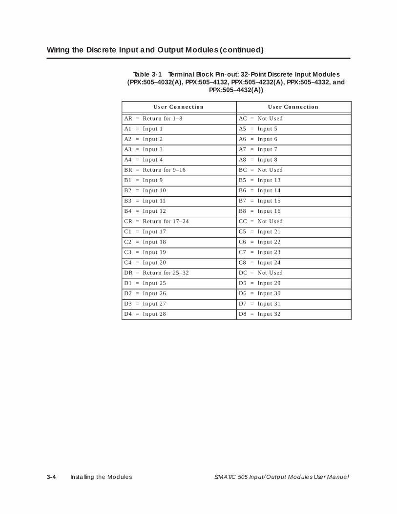
Table 3-1 Terminal Block Pin-out: 32-Point Discrete Input Modules(PPX:505–4032(A), PPX:505–4132, PPX:505–4232(A), PPX:505–4332, and
PPX:505–4432(A))
User Connection User Connection
AR = Return for 1–8 AC = Not Used
A1 = Input 1 A5 = Input 5
A2 = Input 2 A6 = Input 6
A3 = Input 3 A7 = Input 7
A4 = Input 4 A8 = Input 8
BR = Return for 9–16 BC = Not Used
B1 = Input 9 B5 = Input 13
B2 = Input 10 B6 = Input 14
B3 = Input 11 B7 = Input 15
B4 = Input 12 B8 = Input 16
CR = Return for 17–24 CC = Not Used
C1 = Input 17 C5 = Input 21
C2 = Input 18 C6 = Input 22
C3 = Input 19 C7 = Input 23
C4 = Input 20 C8 = Input 24
DR = Return for 25–32 DC = Not Used
D1 = Input 25 D5 = Input 29
D2 = Input 26 D6 = Input 30
D3 = Input 27 D7 = Input 31
D4 = Input 28 D8 = Input 32
Installing the Modules 3-5SIMATIC 505 Input/Output Modules User Manual
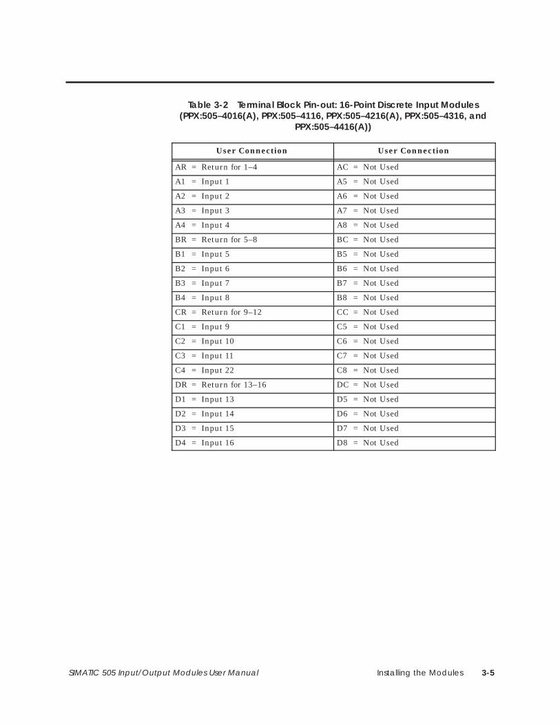
Table 3-2 Terminal Block Pin-out: 16-Point Discrete Input Modules(PPX:505–4016(A), PPX:505–4116, PPX:505–4216(A), PPX:505–4316, and
PPX:505–4416(A))
User Connection User Connection
AR = Return for 1–4 AC = Not Used
A1 = Input 1 A5 = Not Used
A2 = Input 2 A6 = Not Used
A3 = Input 3 A7 = Not Used
A4 = Input 4 A8 = Not Used
BR = Return for 5–8 BC = Not Used
B1 = Input 5 B5 = Not Used
B2 = Input 6 B6 = Not Used
B3 = Input 7 B7 = Not Used
B4 = Input 8 B8 = Not Used
CR = Return for 9–12 CC = Not Used
C1 = Input 9 C5 = Not Used
C2 = Input 10 C6 = Not Used
C3 = Input 11 C7 = Not Used
C4 = Input 22 C8 = Not Used
DR = Return for 13–16 DC = Not Used
D1 = Input 13 D5 = Not Used
D2 = Input 14 D6 = Not Used
D3 = Input 15 D7 = Not Used
D4 = Input 16 D8 = Not Used
Installing the Modules3-6 SIMATIC 505 Input/Output Modules User Manual
Wiring the Discrete Input and Output Modules (continued)
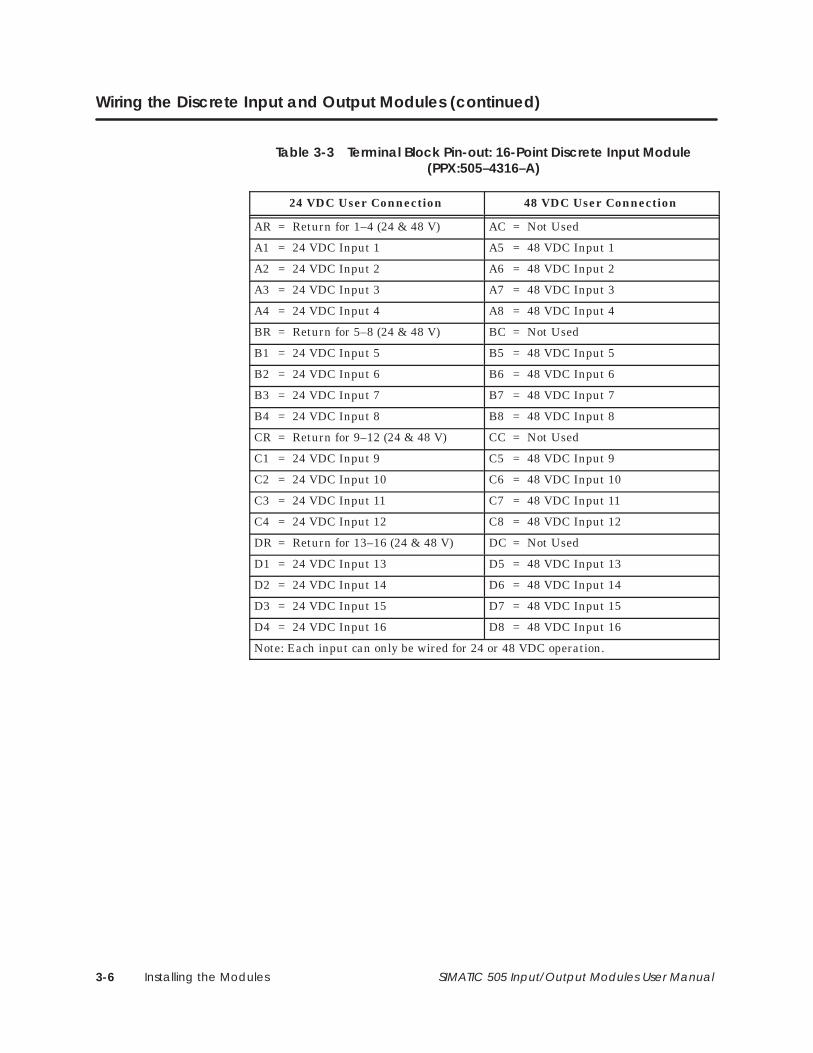
Table 3-3 Terminal Block Pin-out: 16-Point Discrete Input Module(PPX:505–4316–A)
24 VDC User Connection 48 VDC User Connection
AR = Return for 1–4 (24 & 48 V) AC = Not Used
A1 = 24 VDC Input 1 A5 = 48 VDC Input 1
A2 = 24 VDC Input 2 A6 = 48 VDC Input 2
A3 = 24 VDC Input 3 A7 = 48 VDC Input 3
A4 = 24 VDC Input 4 A8 = 48 VDC Input 4
BR = Return for 5–8 (24 & 48 V) BC = Not Used
B1 = 24 VDC Input 5 B5 = 48 VDC Input 5
B2 = 24 VDC Input 6 B6 = 48 VDC Input 6
B3 = 24 VDC Input 7 B7 = 48 VDC Input 7
B4 = 24 VDC Input 8 B8 = 48 VDC Input 8
CR = Return for 9–12 (24 & 48 V) CC = Not Used
C1 = 24 VDC Input 9 C5 = 48 VDC Input 9
C2 = 24 VDC Input 10 C6 = 48 VDC Input 10
C3 = 24 VDC Input 11 C7 = 48 VDC Input 11
C4 = 24 VDC Input 12 C8 = 48 VDC Input 12
DR = Return for 13–16 (24 & 48 V) DC = Not Used
D1 = 24 VDC Input 13 D5 = 48 VDC Input 13
D2 = 24 VDC Input 14 D6 = 48 VDC Input 14
D3 = 24 VDC Input 15 D7 = 48 VDC Input 15
D4 = 24 VDC Input 16 D8 = 48 VDC Input 16
Note: Each input can only be wired for 24 or 48 VDC operation.
Installing the Modules 3-7SIMATIC 505 Input/Output Modules User Manual
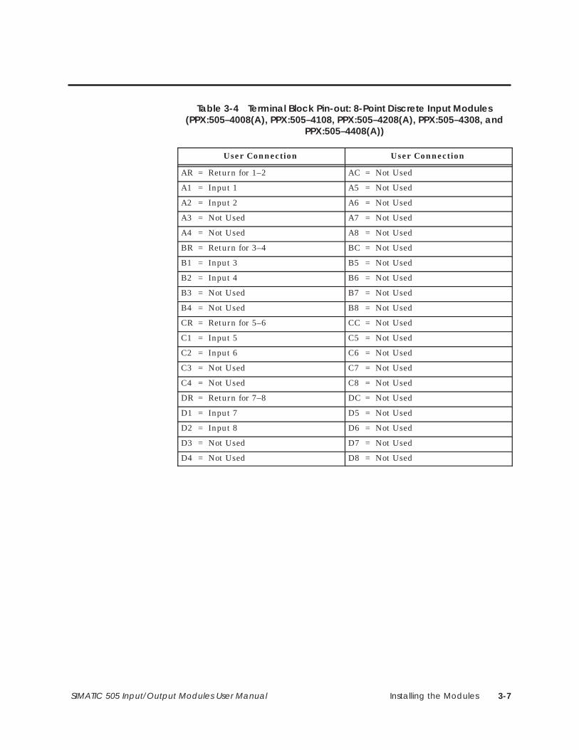
Table 3-4 Terminal Block Pin-out: 8-Point Discrete Input Modules(PPX:505–4008(A), PPX:505–4108, PPX:505–4208(A), PPX:505–4308, and
PPX:505–4408(A))
User Connection User Connection
AR = Return for 1–2 AC = Not Used
A1 = Input 1 A5 = Not Used
A2 = Input 2 A6 = Not Used
A3 = Not Used A7 = Not Used
A4 = Not Used A8 = Not Used
BR = Return for 3–4 BC = Not Used
B1 = Input 3 B5 = Not Used
B2 = Input 4 B6 = Not Used
B3 = Not Used B7 = Not Used
B4 = Not Used B8 = Not Used
CR = Return for 5–6 CC = Not Used
C1 = Input 5 C5 = Not Used
C2 = Input 6 C6 = Not Used
C3 = Not Used C7 = Not Used
C4 = Not Used C8 = Not Used
DR = Return for 7–8 DC = Not Used
D1 = Input 7 D5 = Not Used
D2 = Input 8 D6 = Not Used
D3 = Not Used D7 = Not Used
D4 = Not Used D8 = Not Used

Installing the Modules3-8 SIMATIC 505 Input/Output Modules User Manual
Wiring the Discrete Input and Output Modules (continued)
Table 3-5 Terminal Block Pin-out: 32-Point Discrete AC Output Modules(PPX:505–4632 and PPX:505–4832)
User Connection User Connection
AR = Not Used AC = User-Power
A1 = Output 1 A5 = Output 5
A2 = Output 2 A6 = Output 6
A3 = Output 3 A7 = Output 7
A4 = Output 4 A8 = Output 8
BR = Not Used BC = User-Power
B1 = Output 9 B5 = Output 13
B2 = Output 10 B6 = Output 14
B3 = Output 11 B7 = Output 15
B4 = Output 12 B8 = Output 16
CR = Not Used CC = User-Power
C1 = Output 17 C5 = Output 21
C2 = Output 18 C6 = Output 22
C3 = Output 19 C7 = Output 23
C4 = Output 20 C8 = Output 24
DR = Not Used DC = User-Power
D1 = Output 25 D5 = Output 29
D2 = Output 26 D6 = Output 30
D3 = Output 27 D7 = Output 31
D4 = Output 28 D8 = Output 32
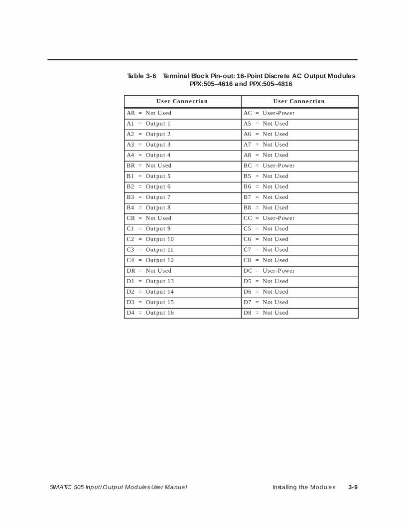
Installing the Modules 3-9SIMATIC 505 Input/Output Modules User Manual
Table 3-6 Terminal Block Pin-out: 16-Point Discrete AC Output ModulesPPX:505–4616 and PPX:505–4816
User Connection User Connection
AR = Not Used AC = User-Power
A1 = Output 1 A5 = Not Used
A2 = Output 2 A6 = Not Used
A3 = Output 3 A7 = Not Used
A4 = Output 4 A8 = Not Used
BR = Not Used BC = User-Power
B1 = Output 5 B5 = Not Used
B2 = Output 6 B6 = Not Used
B3 = Output 7 B7 = Not Used
B4 = Output 8 B8 = Not Used
CR = Not Used CC = User-Power
C1 = Output 9 C5 = Not Used
C2 = Output 10 C6 = Not Used
C3 = Output 11 C7 = Not Used
C4 = Output 12 C8 = Not Used
DR = Not Used DC = User-Power
D1 = Output 13 D5 = Not Used
D2 = Output 14 D6 = Not Used
D3 = Output 15 D7 = Not Used
D4 = Output 16 D8 = Not Used
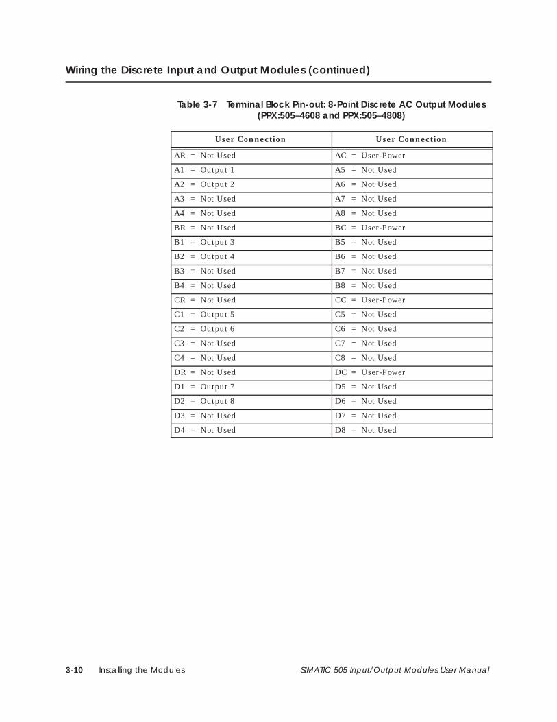
Installing the Modules3-10 SIMATIC 505 Input/Output Modules User Manual
Wiring the Discrete Input and Output Modules (continued)
Table 3-7 Terminal Block Pin-out: 8-Point Discrete AC Output Modules(PPX:505–4608 and PPX:505–4808)
User Connection User Connection
AR = Not Used AC = User-Power
A1 = Output 1 A5 = Not Used
A2 = Output 2 A6 = Not Used
A3 = Not Used A7 = Not Used
A4 = Not Used A8 = Not Used
BR = Not Used BC = User-Power
B1 = Output 3 B5 = Not Used
B2 = Output 4 B6 = Not Used
B3 = Not Used B7 = Not Used
B4 = Not Used B8 = Not Used
CR = Not Used CC = User-Power
C1 = Output 5 C5 = Not Used
C2 = Output 6 C6 = Not Used
C3 = Not Used C7 = Not Used
C4 = Not Used C8 = Not Used
DR = Not Used DC = User-Power
D1 = Output 7 D5 = Not Used
D2 = Output 8 D6 = Not Used
D3 = Not Used D7 = Not Used
D4 = Not Used D8 = Not Used
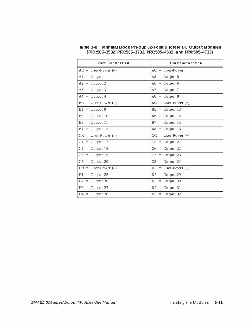
Installing the Modules 3-11SIMATIC 505 Input/Output Modules User Manual
Table 3-8 Terminal Block Pin-out: 32-Point Discrete DC Output Modules(PPX:505–3532, PPX:505–3732, PPX:505–4532, and PPX:505–4732)
User Connection User Connection
AR = User-Power (–) AC = User-Power (+)
A1 = Output 1 A5 = Output 5
A2 = Output 2 A6 = Output 6
A3 = Output 3 A7 = Output 7
A4 = Output 4 A8 = Output 8
BR = User-Power (–) BC = User-Power (+)
B1 = Output 9 B5 = Output 13
B2 = Output 10 B6 = Output 14
B3 = Output 11 B7 = Output 15
B4 = Output 12 B8 = Output 16
CR = User-Power (–) CC = User-Power (+)
C1 = Output 17 C5 = Output 21
C2 = Output 18 C6 = Output 22
C3 = Output 19 C7 = Output 23
C4 = Output 20 C8 = Output 24
DR = User-Power (–) DC = User-Power (+)
D1 = Output 25 D5 = Output 29
D2 = Output 26 D6 = Output 30
D3 = Output 27 D7 = Output 31
D4 = Output 28 D8 = Output 32
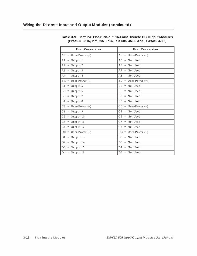
Installing the Modules3-12 SIMATIC 505 Input/Output Modules User Manual
Wiring the Discrete Input and Output Modules (continued)
Table 3-9 Terminal Block Pin-out: 16-Point Discrete DC Output Modules(PPX:505–3516, PPX:505–3716, PPX:505–4516, and PPX:505–4716)
User Connection User Connection
AR = User-Power (–) AC = User-Power (+)
A1 = Output 1 A5 = Not Used
A2 = Output 2 A6 = Not Used
A3 = Output 3 A7 = Not Used
A4 = Output 4 A8 = Not Used
BR = User-Power (–) BC = User-Power (+)
B1 = Output 5 B5 = Not Used
B2 = Output 6 B6 = Not Used
B3 = Output 7 B7 = Not Used
B4 = Output 8 B8 = Not Used
CR = User-Power (–) CC = User-Power (+)
C1 = Output 9 C5 = Not Used
C2 = Output 10 C6 = Not Used
C3 = Output 11 C7 = Not Used
C4 = Output 12 C8 = Not Used
DR = User-Power (–) DC = User-Power (+)
D1 = Output 13 D5 = Not Used
D2 = Output 14 D6 = Not Used
D3 = Output 15 D7 = Not Used
D4 = Output 16 D8 = Not Used
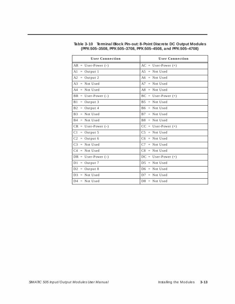
Installing the Modules 3-13SIMATIC 505 Input/Output Modules User Manual
Table 3-10 Terminal Block Pin-out: 8-Point Discrete DC Output Modules(PPX:505–3508, PPX:505–3708, PPX:505–4508, and PPX:505–4708)
User Connection User Connection
AR = User-Power (–) AC = User-Power (+)
A1 = Output 1 A5 = Not Used
A2 = Output 2 A6 = Not Used
A3 = Not Used A7 = Not Used
A4 = Not Used A8 = Not Used
BR = User-Power (–) BC = User-Power (+)
B1 = Output 3 B5 = Not Used
B2 = Output 4 B6 = Not Used
B3 = Not Used B7 = Not Used
B4 = Not Used B8 = Not Used
CR = User-Power (–) CC = User-Power (+)
C1 = Output 5 C5 = Not Used
C2 = Output 6 C6 = Not Used
C3 = Not Used C7 = Not Used
C4 = Not Used C8 = Not Used
DR = User-Power (–) DC = User-Power (+)
D1 = Output 7 D5 = Not Used
D2 = Output 8 D6 = Not Used
D3 = Not Used D7 = Not Used
D4 = Not Used D8 = Not Used
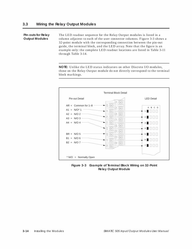
Installing the Modules3-14 SIMATIC 505 Input/Output Modules User Manual
3.3 Wiring the Relay Output Modules
The LED readout sequence for the Relay Output modules is listed in acolumn adjacent to each of the user connector columns. Figure 3-3 shows a32-point module with the corresponding connection between the pin-outguide, the terminal block, and the LED array. Note that the figure is anexample only: the complete LED readout locations are listed in Table 3-11through Table 3-14.
NOTE: Unlike the LED status indicators on other Discrete I/O modules,those on the Relay Output module do not directly correspond to the terminalblock markings.
A B C D
1
2
3
4
5
6
7
Terminal Block Detail
LED DetailPin-out Detail
AR = Common for 1–8
A1 = N/O* 1
A2 = N/O 2
A3 = N/O 3
A4 = N/O 4
* N/O = Normally Open
BR = N/O 5
B1 = N/O 6
B2 = N/O 7
Figure 3-3 Example of Terminal Block Wiring on 32-PointRelay Output Module
Pin-outs for RelayOutput Modules
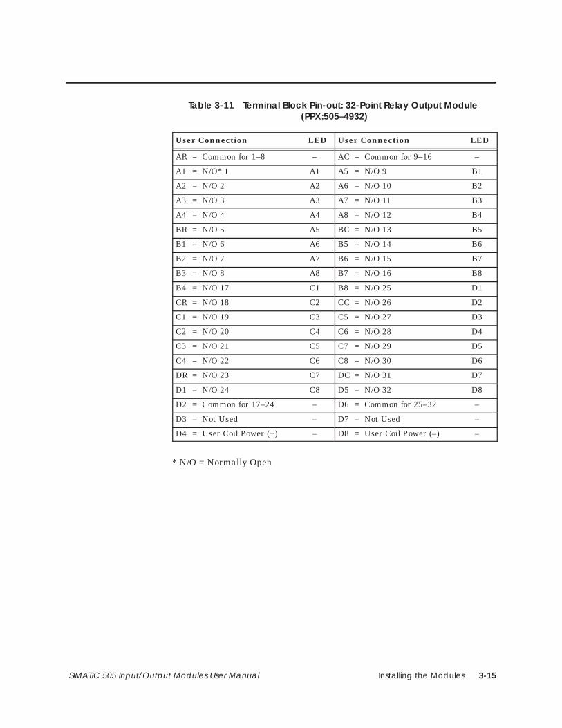
Installing the Modules 3-15SIMATIC 505 Input/Output Modules User Manual
Table 3-11 Terminal Block Pin-out: 32-Point Relay Output Module (PPX:505–4932)
User Connection LED User Connection LED
AR = Common for 1–8 – AC = Common for 9–16 –
A1 = N/O* 1 A1 A5 = N/O 9 B1
A2 = N/O 2 A2 A6 = N/O 10 B2
A3 = N/O 3 A3 A7 = N/O 11 B3
A4 = N/O 4 A4 A8 = N/O 12 B4
BR = N/O 5 A5 BC = N/O 13 B5
B1 = N/O 6 A6 B5 = N/O 14 B6
B2 = N/O 7 A7 B6 = N/O 15 B7
B3 = N/O 8 A8 B7 = N/O 16 B8
B4 = N/O 17 C1 B8 = N/O 25 D1
CR = N/O 18 C2 CC = N/O 26 D2
C1 = N/O 19 C3 C5 = N/O 27 D3
C2 = N/O 20 C4 C6 = N/O 28 D4
C3 = N/O 21 C5 C7 = N/O 29 D5
C4 = N/O 22 C6 C8 = N/O 30 D6
DR = N/O 23 C7 DC = N/O 31 D7
D1 = N/O 24 C8 D5 = N/O 32 D8
D2 = Common for 17–24 – D6 = Common for 25–32 –
D3 = Not Used – D7 = Not Used –
D4 = User Coil Power (+) – D8 = User Coil Power (–) –
* N/O = Normally Open
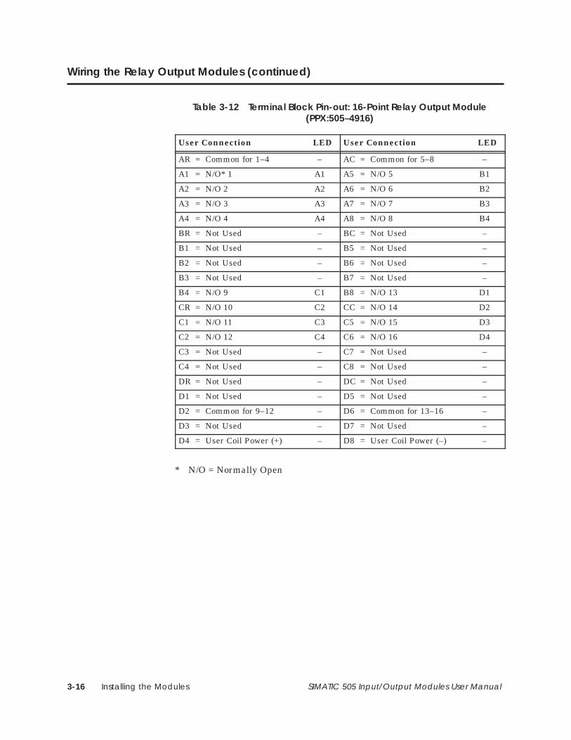
Installing the Modules3-16 SIMATIC 505 Input/Output Modules User Manual
Wiring the Relay Output Modules (continued)
Table 3-12 Terminal Block Pin-out: 16-Point Relay Output Module(PPX:505–4916)
User Connection LED User Connection LED
AR = Common for 1–4 – AC = Common for 5–8 –
A1 = N/O* 1 A1 A5 = N/O 5 B1
A2 = N/O 2 A2 A6 = N/O 6 B2
A3 = N/O 3 A3 A7 = N/O 7 B3
A4 = N/O 4 A4 A8 = N/O 8 B4
BR = Not Used – BC = Not Used –
B1 = Not Used – B5 = Not Used –
B2 = Not Used – B6 = Not Used –
B3 = Not Used – B7 = Not Used –
B4 = N/O 9 C1 B8 = N/O 13 D1
CR = N/O 10 C2 CC = N/O 14 D2
C1 = N/O 11 C3 C5 = N/O 15 D3
C2 = N/O 12 C4 C6 = N/O 16 D4
C3 = Not Used – C7 = Not Used –
C4 = Not Used – C8 = Not Used –
DR = Not Used – DC = Not Used –
D1 = Not Used – D5 = Not Used –
D2 = Common for 9–12 – D6 = Common for 13–16 –
D3 = Not Used – D7 = Not Used –
D4 = User Coil Power (+) – D8 = User Coil Power (–) –
* N/O = Normally Open
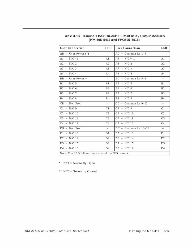
Installing the Modules 3-17SIMATIC 505 Input/Output Modules User Manual
Table 3-13 Terminal Block Pin-out: 16-Point Relay Output Modules(PPX:505–5417 and PPX:505–5518)
User Connection LED User Connection LED
AR = User-Power (–) – AC = Common for 1–4 –
A1 = N/O* 1 A1 A5 = N/C** 1 A1
A2 = N/O 2 A2 A6 = N/C 2 A2
A3 = N/O 3 A3 A7 = N/C 3 A3
A4 = N/O 4 A4 A8 = N/C 4 A4
BR = User-Power + – BC = Common for 5–8 –
B1 = N/O 5 B1 B5 = N/C 5 B1
B2 = N/O 6 B2 B6 = N/C 6 B2
B3 = N/O 7 B3 B7 = N/C 7 B3
B4 = N/O 8 B4 B8 = N/C 8 B4
CR = Not Used – CC = Common for 9–12 –
C1 = N/O 9 C1 C5 = N/C 9 C1
C2 = N/O 10 C2 C6 = N/C 10 C2
C3 = N/O 11 C3 C7 = N/C 11 C3
C4 = N/O 12 C4 C8 = N/C 12 C4
DR = Not Used – DC = Common for 13–16 –
D1 = N/O 13 D1 D5 = N/C 13 D1
D2 = N/O 14 D2 D6 = N/C 14 D2
D3 = N/O 15 D3 D7 = N/C 15 D3
D4 = N/O 16 D4 D8 = N/C 16 D4
Note: The LED follows the status of the N/O contact.
* N/O = Normally Open
** N/C = Normally Closed
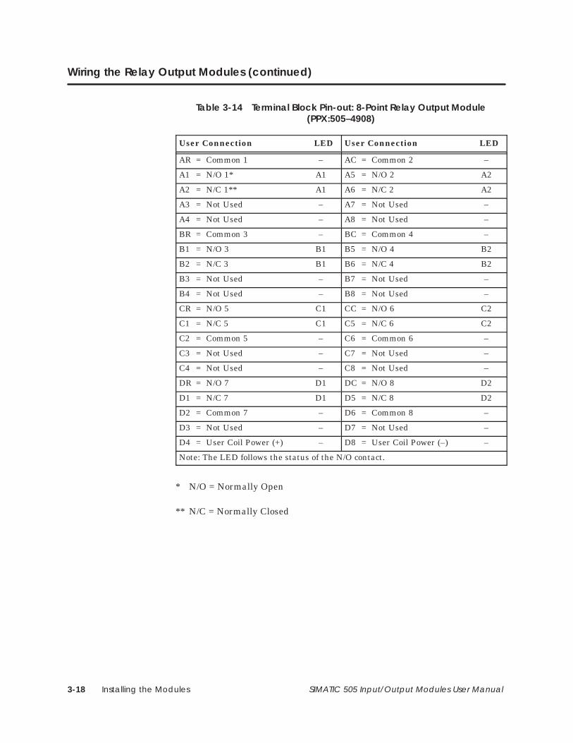
Installing the Modules3-18 SIMATIC 505 Input/Output Modules User Manual
Wiring the Relay Output Modules (continued)
Table 3-14 Terminal Block Pin-out: 8-Point Relay Output Module(PPX:505–4908)
User Connection LED User Connection LED
AR = Common 1 – AC = Common 2 –
A1 = N/O 1* A1 A5 = N/O 2 A2
A2 = N/C 1** A1 A6 = N/C 2 A2
A3 = Not Used – A7 = Not Used –
A4 = Not Used – A8 = Not Used –
BR = Common 3 – BC = Common 4 –
B1 = N/O 3 B1 B5 = N/O 4 B2
B2 = N/C 3 B1 B6 = N/C 4 B2
B3 = Not Used – B7 = Not Used –
B4 = Not Used – B8 = Not Used –
CR = N/O 5 C1 CC = N/O 6 C2
C1 = N/C 5 C1 C5 = N/C 6 C2
C2 = Common 5 – C6 = Common 6 –
C3 = Not Used – C7 = Not Used –
C4 = Not Used – C8 = Not Used –
DR = N/O 7 D1 DC = N/O 8 D2
D1 = N/C 7 D1 D5 = N/C 8 D2
D2 = Common 7 – D6 = Common 8 –
D3 = Not Used – D7 = Not Used –
D4 = User Coil Power (+) – D8 = User Coil Power (–) –
Note: The LED follows the status of the N/O contact.
* N/O = Normally Open
** N/C = Normally Closed
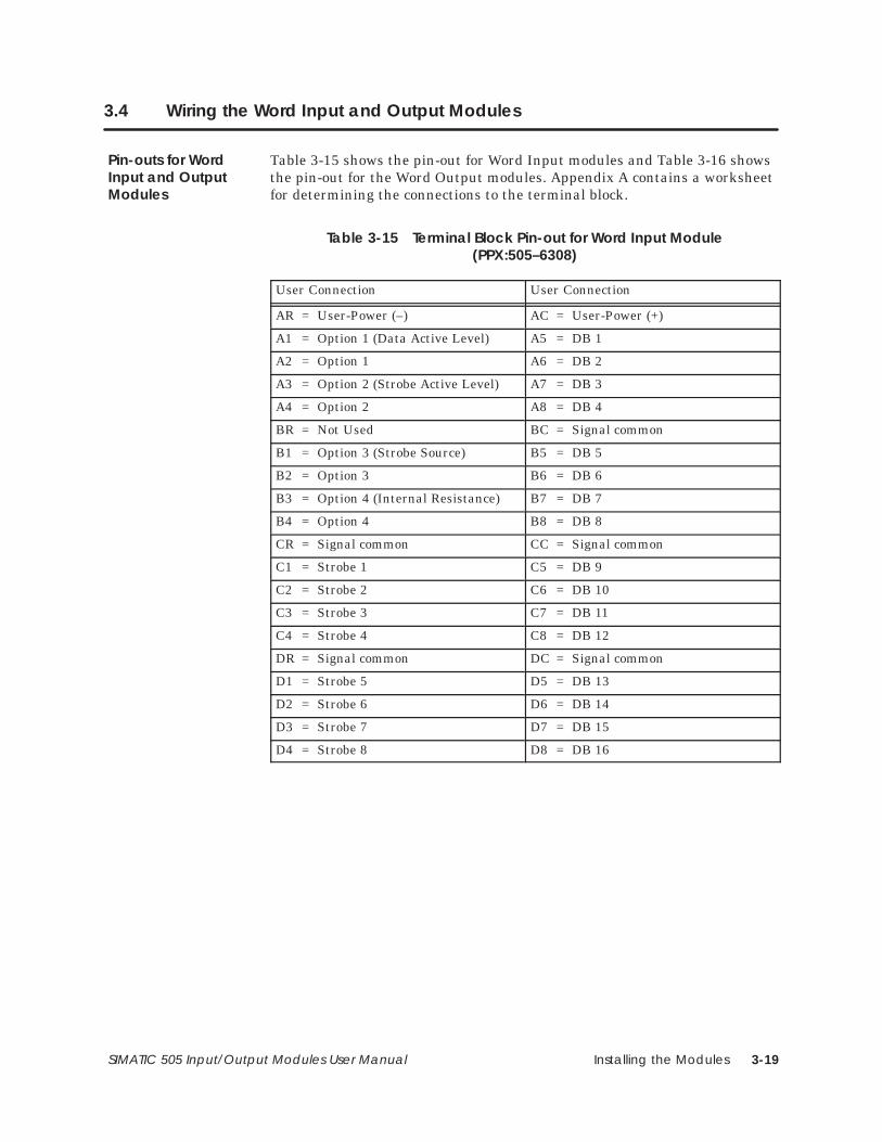
Installing the Modules 3-19SIMATIC 505 Input/Output Modules User Manual
3.4 Wiring the Word Input and Output Modules
Table 3-15 shows the pin-out for Word Input modules and Table 3-16 showsthe pin-out for the Word Output modules. Appendix A contains a worksheetfor determining the connections to the terminal block.
Table 3-15 Terminal Block Pin-out for Word Input Module(PPX:505–6308)
User Connection User Connection
AR = User-Power (–) AC = User-Power (+)
A1 = Option 1 (Data Active Level) A5 = DB 1
A2 = Option 1 A6 = DB 2
A3 = Option 2 (Strobe Active Level) A7 = DB 3
A4 = Option 2 A8 = DB 4
BR = Not Used BC = Signal common
B1 = Option 3 (Strobe Source) B5 = DB 5
B2 = Option 3 B6 = DB 6
B3 = Option 4 (Internal Resistance) B7 = DB 7
B4 = Option 4 B8 = DB 8
CR = Signal common CC = Signal common
C1 = Strobe 1 C5 = DB 9
C2 = Strobe 2 C6 = DB 10
C3 = Strobe 3 C7 = DB 11
C4 = Strobe 4 C8 = DB 12
DR = Signal common DC = Signal common
D1 = Strobe 5 D5 = DB 13
D2 = Strobe 6 D6 = DB 14
D3 = Strobe 7 D7 = DB 15
D4 = Strobe 8 D8 = DB 16
Pin-outs for WordInput and OutputModules
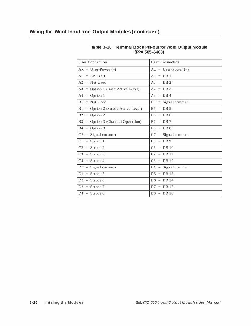
Installing the Modules3-20 SIMATIC 505 Input/Output Modules User Manual
Wiring the Word Input and Output Modules (continued)
Table 3-16 Terminal Block Pin-out for Word Output Module(PPX:505–6408)
User Connection User Connection
AR = User-Power (–) AC = User-Power (+)
A1 = EPF Out A5 = DB 1
A2 = Not Used A6 = DB 2
A3 = Option 1 (Data Active Level) A7 = DB 3
A4 = Option 1 A8 = DB 4
BR = Not Used BC = Signal common
B1 = Option 2 (Strobe Active Level) B5 = DB 5
B2 = Option 2 B6 = DB 6
B3 = Option 3 (Channel Operation) B7 = DB 7
B4 = Option 3 B8 = DB 8
CR = Signal common CC = Signal common
C1 = Strobe 1 C5 = DB 9
C2 = Strobe 2 C6 = DB 10
C3 = Strobe 3 C7 = DB 11
C4 = Strobe 4 C8 = DB 12
DR = Signal common DC = Signal common
D1 = Strobe 5 D5 = DB 13
D2 = Strobe 6 D6 = DB 14
D3 = Strobe 7 D7 = DB 15
D4 = Strobe 8 D8 = DB 16
Installing the Modules 3-21SIMATIC 505 Input/Output Modules User Manual
Wiring the Word Input and Output modules consists of wiring theuser-provided power supply, and wiring the input signals and jumpers. Allconnections are made at the module terminal block. The power supplywiring should be separated from the signal wiring to avoid introducing noiseon the input data lines.
Make the power connections at the top two terminals: AR (negative) and AC(positive).
Connect the data lines to the terminals on the right side of the terminalblock. The data lines are designated DB1–DB16 in Table 3-15 andTable 3-16; DB16 is the least significant bit.
Terminate the shields for the data lines at the source of the signal, andconnect the return lines to the signal common terminals on the terminalblock. The five signal common terminals are labeled BC, CC, DC, CR, andDR. These terminals are linked internally. Signal common connections canbe made to any of these five terminals.
Because the input data lines are multiplexed on the Word Input modules,the devices connected to them must have tri-state outputs or open collectoroutputs. Diodes may also be used to isolate field devices, as shown inFigure 3-4.
Avoiding NoiseProblems
Connections andTerminations
Installing the Modules3-22 SIMATIC 505 Input/Output Modules User Manual
Wiring the Word Input and Output Modules (continued)
The strobe lines are connected to the C and D group of terminals on the leftside of the terminal block. The strobe lines are designated Strobe 1 throughStrobe 8, where Strobe 1 corresponds to Word number 1 (WY1).
Transmission distance for the module-generated strobes is determined bycable size.
• Use up to 10 feet for AWG #20 ribbon cable with interleaved signalreturns terminated at both ends.
• Use up to 30 feet for AWG #18 shielded, twisted pair cable.
Use supply wires suitable for at least 75° C. Signal wiring connectedin this box must be rated at least 300 V.
Employer des fils d’alimentation pour au moins 75° C. Le cablage designalisation raccordé dans cette boîte doit convenir pour unetension nominale d’au moins 300 V.
The shielding for the cable should be terminated at the source end of thesignal. Use the earth ground to which the base is connected to terminate thecable shielding.
Figure 3-4 shows the connections for the blocking diodes for multiplethumbwheels that use high true module-generated strobes. If you use thisconfiguration:
• Install jumper one for a high true data active level
• Install jumper two for high true strobes
• Install jumper four for pull-down resistors
CAUTION!
ATTENTION!
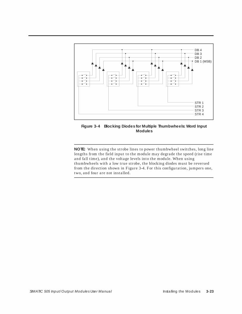
Installing the Modules 3-23SIMATIC 505 Input/Output Modules User Manual
DB 4DB 3DB 2DB 1 (MSB)
STR 1STR 2STR 3STR 4
Figure 3-4 Blocking Diodes for Multiple Thumbwheels: Word InputModules
NOTE: When using the strobe lines to power thumbwheel switches, long linelengths from the field input to the module may degrade the speed (rise timeand fall time), and the voltage levels into the module. When usingthumbwheels with a low true strobe, the blocking diodes must be reversedfrom the direction shown in Figure 3-4. For this configuration, jumpers one,two, and four are not installed.
Installing the Modules3-24 SIMATIC 505 Input/Output Modules User Manual
3.5 Field Wiring
To minimize unwanted noise, follow these wiring installation guidelines.
• Use the shortest possible wires.
• Separate discrete and analog wires.
• Avoid placing signal wires parallel to high-energy wires. If the twomust meet, cross them at right angles.
• Avoid bending the wire into sharp angles.
• Use wireways for wire routing.
• When using shielded wires, ground them only at the source end forbetter noise immunity.
• Place wires so that they do not interfere with existing wiring.
• Label the wires.
You must use supply wires suitable for at least 75° C. Signal wiringconnected in this box must be rated at least 300 V.
Employer des fils d’alimentation pour au moins 75° C. Le cablage designalisation raccordé dans cette boîte doit convenir pour unetension nominale d’au moins 300 V.
WiringRecommendations
CAUTION!
ATTENTION!
Installing the Modules 3-25SIMATIC 505 Input/Output Modules User Manual
You can use either of the terminal blocks shown in Figure 3-5. Bothterminal blocks are removable. To wire the terminal block, follow theprocedure below.
1. Turn the terminal block, with the screw-heads facing you, until the Aseries of terminals is at the top and the D series is at the bottom.
2. Using Table 3-1 through Table 3-16 as wiring guides, start with the Dseries and loosen the appropriate terminal block screws.
3. Strip back the insulation on the wires about 1/4″ to 3/8″ (or onecentimeter). Use a 12–26 AWG or a 0.16–3.2 mm2 metric gauge wire ofeither stranded or solid type.
(If you are using the side-accessible connector number,PPX:2587705–8010, a spade or a ring lug may be attached to the end ofthe wire.)
4. Connect the end of the wire to the loosened terminal block screw andtighten the screw firmly. Once the D series is completed, connect the Cseries, and continue until the terminal block is completely wired.
NOTE: An easy-to-use, stick-on label is provided separately with spaceavailable to write in the name of each input. Write in the correspondinginput or output names and apply the label to the flat side of the terminalblock. Appendix A contains a worksheet to help you document the input andoutput labeling.
Wiring the TerminalBlock
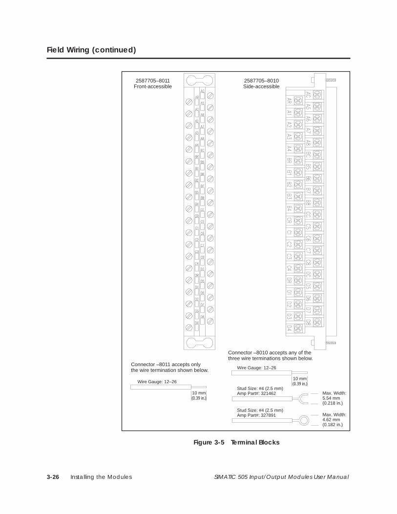
Installing the Modules3-26 SIMATIC 505 Input/Output Modules User Manual
Field Wiring (continued)
10 mm(0.39 in.)
Wire Gauge: 12–26
Max. Width:5.54 mm(0.218 in.)
Stud Size: #4 (2.5 mm)Amp Part#: 321462
Max. Width:4.62 mm (0.182 in.)
Stud Size: #4 (2.5 mm)Amp Part#: 327891
2587705–8011Front-accessible
10 mm(0.39 in.)
Wire Gauge: 12–26
Connector –8010 accepts any of thethree wire terminations shown below.
Connector –8011 accepts onlythe wire termination shown below.
2587705–8010Side-accessible
Figure 3-5 Terminal Blocks
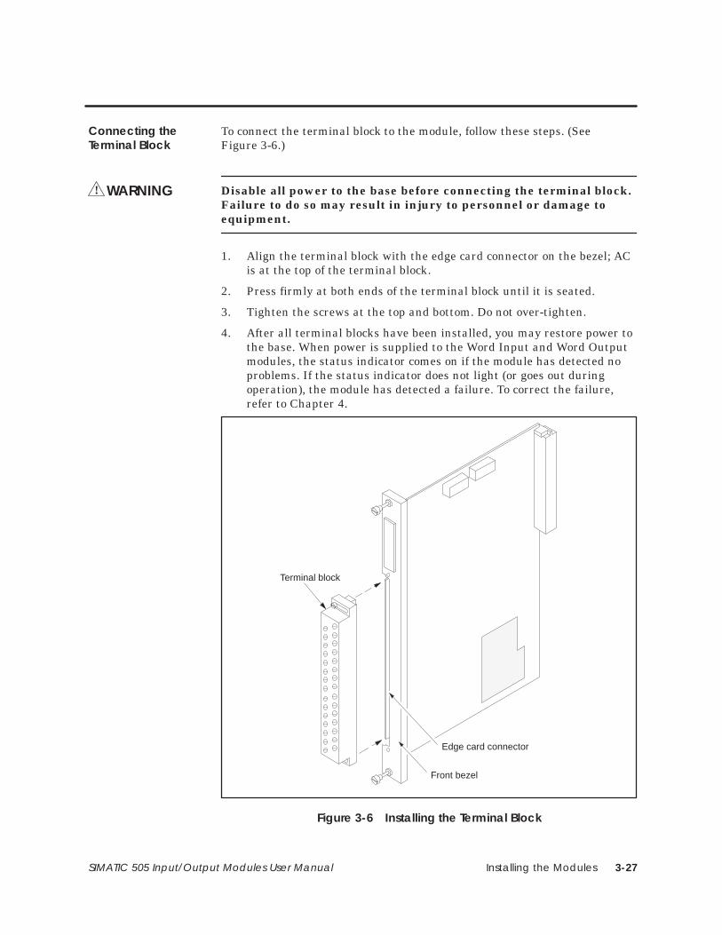
Installing the Modules 3-27SIMATIC 505 Input/Output Modules User Manual
To connect the terminal block to the module, follow these steps. (SeeFigure 3-6.)
Disable all power to the base before connecting the terminal block.Failure to do so may result in injury to personnel or damage toequipment.
1. Align the terminal block with the edge card connector on the bezel; ACis at the top of the terminal block.
2. Press firmly at both ends of the terminal block until it is seated.
3. Tighten the screws at the top and bottom. Do not over-tighten.
4. After all terminal blocks have been installed, you may restore power tothe base. When power is supplied to the Word Input and Word Outputmodules, the status indicator comes on if the module has detected noproblems. If the status indicator does not light (or goes out duringoperation), the module has detected a failure. To correct the failure,refer to Chapter 4.
Terminal block
Edge card connector
Front bezel
Figure 3-6 Installing the Terminal Block
Connecting theTerminal Block
WARNING!
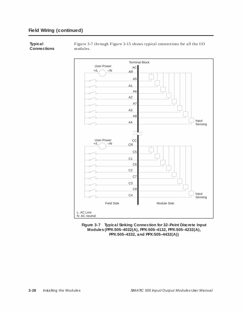
Installing the Modules3-28 SIMATIC 505 Input/Output Modules User Manual
Field Wiring (continued)
Figure 3-7 through Figure 3-15 shows typical connections for all the I/Omodules.
ACAR
A5
A1
A6
A2
A7
A3
A8
A4
+/L –/N
InputSensing
CCCR
C5
C1
C6
C2
C7
C3
C8
C4
+/L –/N
InputSensing
Field Side Module Side
Terminal BlockUser-Power
User-Power
L: AC LineN: AC neutral
Figure 3-7 Typical Sinking Connection for 32–Point Discrete InputModules (PPX:505–4032(A), PPX:505–4132, PPX:505–4232(A),
PPX:505–4332, and PPX:505–4432(A))
TypicalConnections
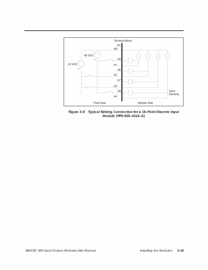
Installing the Modules 3-29SIMATIC 505 Input/Output Modules User Manual
ACAR
A5
A1
A6
A2
A7
A3
A8
A4
–
InputSensing
Field Side Module Side
Terminal Block
+
48 VDC
–
+
24 VDC
Figure 3-8 Typical Sinking Connection for a 16–Point Discrete InputModule (PPX:505–4316–A)
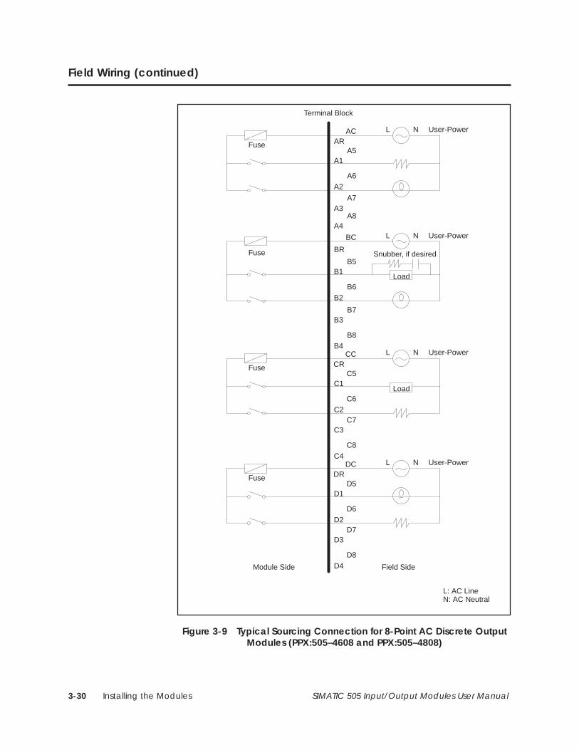
Installing the Modules3-30 SIMATIC 505 Input/Output Modules User Manual
Field Wiring (continued)
ACAR
A5A1
L N User-Power
A6A2
Fuse
A7A3
A8A4
BC
BR
B5B1
L N User-Power
B6B2
Fuse
B7B3
B8B4
CCCR
C5C1
L N User-Power
C6C2
Fuse
C7C3
C8C4
DCDR
D5D1
L N User-Power
D6D2
Fuse
D7D3
D8
D4
Load
Snubber, if desired
Load
Field SideModule Side
Terminal Block
L: AC LineN: AC Neutral
Figure 3-9 Typical Sourcing Connection for 8-Point AC Discrete OutputModules (PPX:505–4608 and PPX:505–4808)
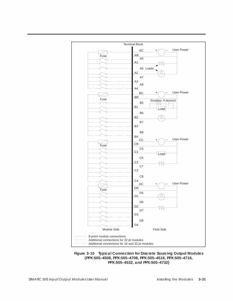
Installing the Modules 3-31SIMATIC 505 Input/Output Modules User Manual
AC
ARA5
A1
User-Power
A6A2
Fuse
A7A3
A8A4
BCBR
B5B1
User-Power
B6B2
Fuse
B7B3
B8B4
CCCR
C5C1
User-Power
C6C2
Fuse
C7C3
C8C4
DCDR
D5D1
User-Power
D6D2
Fuse
D7D3
D8D4
Load
Snubber, if desired
Load
Field SideModule Side
Loads
Terminal Block
Additional connections for 32 pt modulesAdditional connections for 16 and 32 pt modules
8-point module connections
+ –
+ –
+ –
+ –
Figure 3-10 Typical Connection for Discrete Sourcing Output Modules(PPX:505–4508, PPX:505–4708, PPX:505–4516, PPX:505–4716,
PPX:505–4532, and PPX:505–4732)
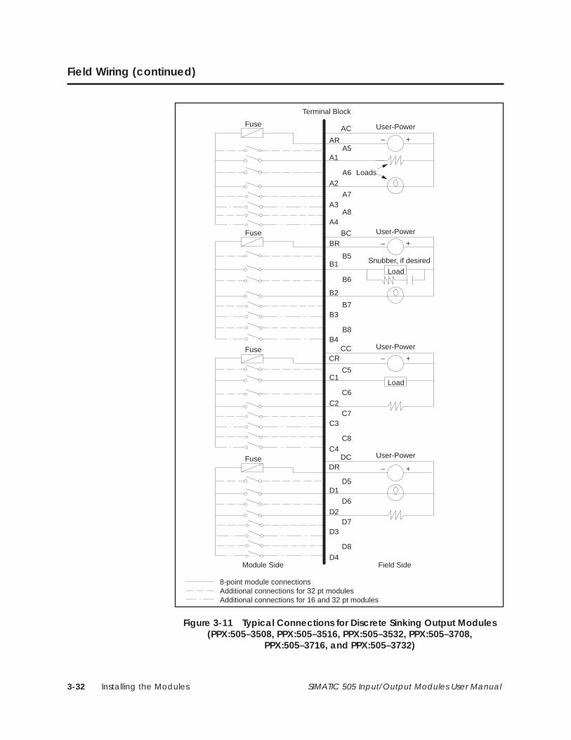
Installing the Modules3-32 SIMATIC 505 Input/Output Modules User Manual
Field Wiring (continued)
AC
ARA5
A1
User-Power
A6A2
A7A3
A8A4
BCBR
B5B1
User-Power
B6
B2
B7B3
B8B4
CCCR
C5C1
User-Power
C6C2
C7C3
C8C4
DCDR
D5D1
User-Power
D6D2
D7D3
D8
D4
Load
Snubber, if desired
Load
Field SideModule Side
Loads
Terminal Block
Fuse
Fuse
Additional connections for 32 pt modulesAdditional connections for 16 and 32 pt modules
8-point module connections
Fuse
Fuse
+–
+–
+–
+–
Figure 3-11 Typical Connections for Discrete Sinking Output Modules(PPX:505–3508, PPX:505–3516, PPX:505–3532, PPX:505–3708,
PPX:505–3716, and PPX:505–3732)
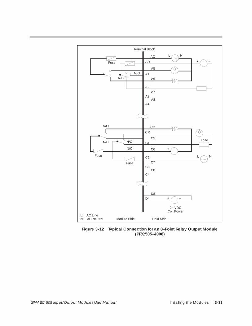
Installing the Modules 3-33SIMATIC 505 Input/Output Modules User Manual
AC
AR
A5
A1A6
A2
A7A3
A8A4
D8D4
Field SideModule Side
Terminal Block
Fuse
L N
N/ON/C
CC
CR
C5C1
C6
C2
C7C3
C8C4
L N
N/O
N/C
N/O
Load
Fuse
Fuse
24 VDCCoil Power
N/C
L: AC LineN: AC Neutral
+ –
+ –
+ –
Figure 3-12 Typical Connection for an 8–Point Relay Output Module(PPX:505–4908)
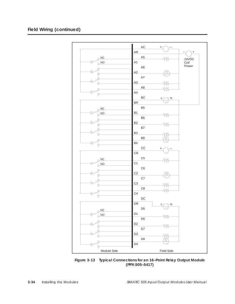
Installing the Modules3-34 SIMATIC 505 Input/Output Modules User Manual
Field Wiring (continued)
AC
AR
A5
A1
A6
A2
A7
A3
A8
A4
BC
BR
B5
B1
B6
B2
B7
B3
B8
B4
CC
CR
C5
C1
C6
C2
C7
C3
C8
C4
DC
DR
D5
D1
D6
D2
D7
D3
D8
D4
NC
NO
NC
NO
L N
NC
NO
NC
NO
L N
24VDCCoilPower
Field SideModule Side
+–
+ –
+ –
Figure 3-13 Typical Connections for an 16–Point Relay Output Module(PPX:505–5417)
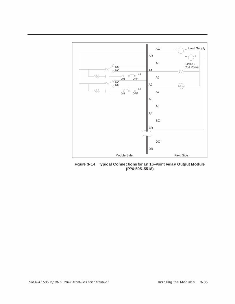
Installing the Modules 3-35SIMATIC 505 Input/Output Modules User Manual
AC
AR
A5
A1
A6
A2
A7
A3
A8
A4
BC
BR
DC
DR
NCNO
+ –
24VDCCoil Power
Field SideModule Side
Load Supply
ON OFF
E1
ON OFF
E2
NCNO
+–
Figure 3-14 Typical Connections for an 16–Point Relay Output Module(PPX:505–5518)
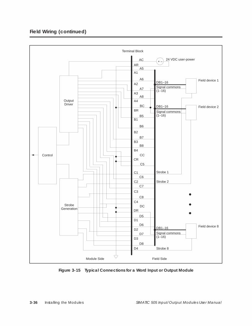
Installing the Modules3-36 SIMATIC 505 Input/Output Modules User Manual
Field Wiring (continued)
Signal commons(1–16)
AC
ARA5
A1
A6
A2
A7A3
A8A4
BCBR
B5B1
B6
B2
B7B3
B8B4
CCCR
C5
C1C6
C2C7
C3
C8
C4DC
DR
D5D1
D6
D2D7
D3
D8D4
Field SideModule Side
Terminal Block
+ –
OutputDriver
StrobeGeneration
Control
24 VDC user-power
Field device 1
Field device 2
DB1–16
DB1–16
Signal commons(1–16)
Field device 8
Signal commons(1–16)
DB1–16
Strobe 1
Strobe 2
Strobe 8
Figure 3-15 Typical Connections for a Word Input or Output Module
Installing the Modules 3-37SIMATIC 505 Input/Output Modules User Manual
3.6 Connecting Discrete Output Modules
The Discrete AC Output modules are both sourcing and sinking. Therefore,the outputs operate when wired in either a sourcing or a sinkingconfiguration. AC modules do not have blown-fuse indicators.
On AC or DC modules, the module may be damaged if more thanone channel is overloaded simultaneously, or if the temporaryoverload specification is exceeded.
The Discrete DC Output modules (PPX:505–45xx and PPX:505–47xx) aresourcing outputs, and do not function unless the module is wired correctly.The Discrete DC Output modules (PPX:505–35xx and PPX:505–37xx) aresinking outputs, and do not function unless the module is wired correctly. Ifthe user-power is incorrectly connected, the fuse blows; however, theblown-fuse indicator does not light until power is properly connected. (Notethat reverse polarity connections within the ratings of the device does notcause damage to the device.)
AC and DC OutputModules
CAUTION!
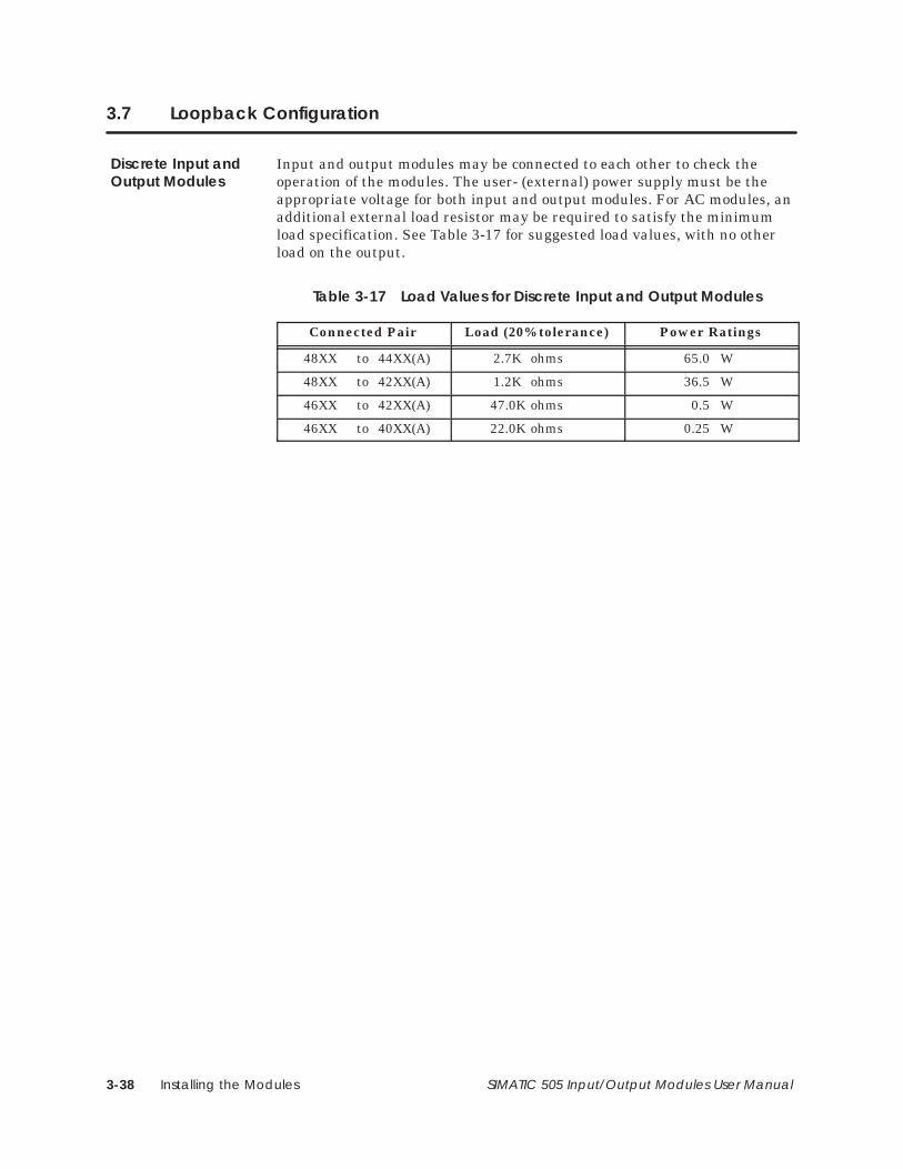
Installing the Modules3-38 SIMATIC 505 Input/Output Modules User Manual
3.7 Loopback Configuration
Input and output modules may be connected to each other to check theoperation of the modules. The user- (external) power supply must be theappropriate voltage for both input and output modules. For AC modules, anadditional external load resistor may be required to satisfy the minimumload specification. See Table 3-17 for suggested load values, with no otherload on the output.
Table 3-17 Load Values for Discrete Input and Output Modules
Connected Pair Load (20% tolerance) Power Ratings
48XX to 44XX(A) 2.7K ohms 65.0 W
48XX to 42XX(A) 1.2K ohms 36.5 W
46XX to 42XX(A) 47.0K ohms 0.5 W
46XX to 40XX(A) 22.0K ohms 0.25 W
Discrete Input andOutput Modules
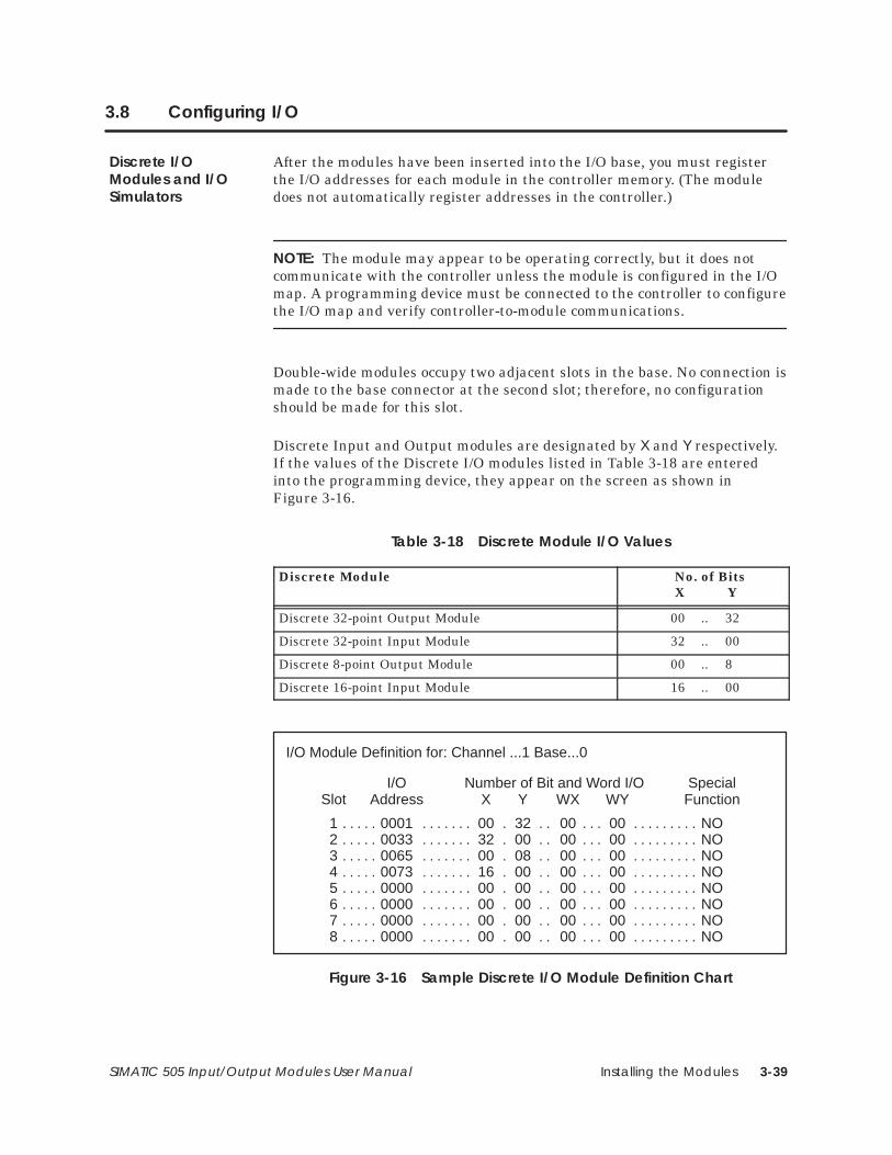
Installing the Modules 3-39SIMATIC 505 Input/Output Modules User Manual
3.8 Configuring I/O
After the modules have been inserted into the I/O base, you must registerthe I/O addresses for each module in the controller memory. (The moduledoes not automatically register addresses in the controller.)
NOTE: The module may appear to be operating correctly, but it does notcommunicate with the controller unless the module is configured in the I/Omap. A programming device must be connected to the controller to configurethe I/O map and verify controller-to-module communications.
Double-wide modules occupy two adjacent slots in the base. No connection ismade to the base connector at the second slot; therefore, no configurationshould be made for this slot.
Discrete Input and Output modules are designated by X and Y respectively.If the values of the Discrete I/O modules listed in Table 3-18 are enteredinto the programming device, they appear on the screen as shown inFigure 3-16.
Table 3-18 Discrete Module I/O Values
Discrete Module No. of BitsX Y
Discrete 32-point Output Module 00 .. 32
Discrete 32-point Input Module 32 .. 00
Discrete 8-point Output Module 00 .. 8
Discrete 16-point Input Module 16 .. 00
I/O Module Definition for: Channel ...1 Base...0
I/O Number of Bit and Word I/O SpecialSlot Address X Y WX WY Function
1 0001 00 32 00 00 NO. . . . . . . . . . . . . . . . . . . . . . . . . . . 2 0033 32 00 00 00 NO. . . . . . . . . . . . . . . . . . . . . . . . . . . 3 0065 00 08 00 00 NO. . . . . . . . . . . . . . . . . . . . . . . . . . . 4 0073 16 00 00 00 NO. . . . . . . . . . . . . . . . . . . . . . . . . . . 5 0000 00 00 00 00 NO. . . . . . . . . . . . . . . . . . . . . . . . . . . 6 0000 00 00 00 00 NO. . . . . . . . . . . . . . . . . . . . . . . . . . . 7 0000 00 00 00 00 NO. . . . . . . . . . . . . . . . . . . . . . . . . . . 8 0000 00 00 00 00 NO. . . . . . . . . . . . . . . . . . . . . . . . . . .
Figure 3-16 Sample Discrete I/O Module Definition Chart
Discrete I/OModules and I/OSimulators
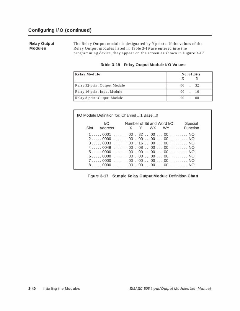
Installing the Modules3-40 SIMATIC 505 Input/Output Modules User Manual
Configuring I/O (continued)
The Relay Output module is designated by Y points. If the values of theRelay Output modules listed in Table 3-19 are entered into theprogramming device, they appear on the screen as shown in Figure 3-17.
Table 3-19 Relay Output Module I/O Values
Relay Module No. of BitsX Y
Relay 32-point Output Module 00 .. 32
Relay 16-point Input Module 00 .. 16
Relay 8-point Output Module 00 .. 08
I/O Module Definition for: Channel ...1 Base...0
I/O Number of Bit and Word I/O SpecialSlot Address X Y WX WY Function
1 0001 00 32 00 00 NO. . . . . . . . . . . . . . . . . . . . . . . . . . . 2 0000 00 00 00 00 NO. . . . . . . . . . . . . . . . . . . . . . . . . . . 3 0033 00 16 00 00 NO. . . . . . . . . . . . . . . . . . . . . . . . . . . 4 0049 00 08 00 00 NO. . . . . . . . . . . . . . . . . . . . . . . . . . . 5 0000 00 00 00 00 NO. . . . . . . . . . . . . . . . . . . . . . . . . . . 6 0000 00 00 00 00 NO. . . . . . . . . . . . . . . . . . . . . . . . . . . 7 0000 00 00 00 00 NO. . . . . . . . . . . . . . . . . . . . . . . . . . . 8 0000 00 00 00 00 NO. . . . . . . . . . . . . . . . . . . . . . . . . . .
Figure 3-17 Sample Relay Output Module Definition Chart
Relay OutputModules
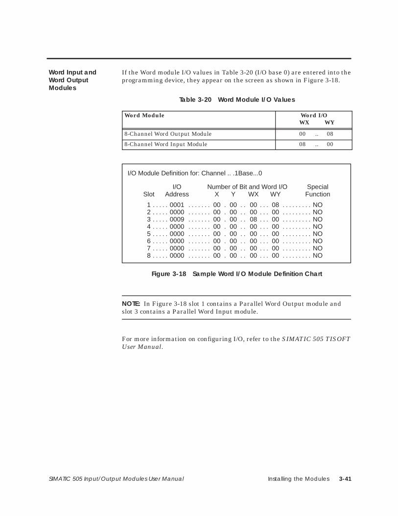
Installing the Modules 3-41SIMATIC 505 Input/Output Modules User Manual
If the Word module I/O values in Table 3-20 (I/O base 0) are entered into theprogramming device, they appear on the screen as shown in Figure 3-18.
Table 3-20 Word Module I/O Values
Word Module Word I/OWX WY
8-Channel Word Output Module 00 .. 08
8-Channel Word Input Module 08 .. 00
I/O Module Definition for: Channel .. .1Base...0
I/O Number of Bit and Word I/O SpecialSlot Address X Y WX WY Function
1 0001 00 00 00 08 NO. . . . . . . . . . . . . . . . . . . . . . . . . . . 2 0000 00 00 00 00 NO. . . . . . . . . . . . . . . . . . . . . . . . . . . 3 0009 00 00 08 00 NO. . . . . . . . . . . . . . . . . . . . . . . . . . . 4 0000 00 00 00 00 NO. . . . . . . . . . . . . . . . . . . . . . . . . . . 5 0000 00 00 00 00 NO. . . . . . . . . . . . . . . . . . . . . . . . . . . 6 0000 00 00 00 00 NO. . . . . . . . . . . . . . . . . . . . . . . . . . . 7 0000 00 00 00 00 NO. . . . . . . . . . . . . . . . . . . . . . . . . . . 8 0000 00 00 00 00 NO. . . . . . . . . . . . . . . . . . . . . . . . . . .
Figure 3-18 Sample Word I/O Module Definition Chart
NOTE: In Figure 3-18 slot 1 contains a Parallel Word Output module andslot 3 contains a Parallel Word Input module.
For more information on configuring I/O, refer to the SIMATIC 505 TISOFTUser Manual.
Word Input andWord OutputModules
Troubleshooting 4-1SIMATIC 505 Input/Output Modules User Manual
Chapter 4
Troubleshooting
4.1 LED Status Indicators 4-2. . . . . . . . . . . . . . . . . . . . . . . . . . . . . . . . . . . . . . . . . . . . . . . . . . . . . . . . . . . . Discrete Input and Output Modules 4-2. . . . . . . . . . . . . . . . . . . . . . . . . . . . . . . . . . . . . . . . . . . . . . Relay Output Modules 4-3. . . . . . . . . . . . . . . . . . . . . . . . . . . . . . . . . . . . . . . . . . . . . . . . . . . . . . . . . . Word Input and Word Output Modules 4-4. . . . . . . . . . . . . . . . . . . . . . . . . . . . . . . . . . . . . . . . . . . For Assistance 4-4. . . . . . . . . . . . . . . . . . . . . . . . . . . . . . . . . . . . . . . . . . . . . . . . . . . . . . . . . . . . . . . . . .
4.2 Replacing a Fuse 4-5. . . . . . . . . . . . . . . . . . . . . . . . . . . . . . . . . . . . . . . . . . . . . . . . . . . . . . . . . . . . . . . Discrete Output, Relay Output, Word Input, and Word Output Modules 4-5. . . . . . . . . . . . For Assistance 4-5. . . . . . . . . . . . . . . . . . . . . . . . . . . . . . . . . . . . . . . . . . . . . . . . . . . . . . . . . . . . . . . . . .
4.3 Replacing a Relay 4-6. . . . . . . . . . . . . . . . . . . . . . . . . . . . . . . . . . . . . . . . . . . . . . . . . . . . . . . . . . . . . . Relay Output Modules 4-6. . . . . . . . . . . . . . . . . . . . . . . . . . . . . . . . . . . . . . . . . . . . . . . . . . . . . . . . . . Replacing a Damaged Relay 4-6. . . . . . . . . . . . . . . . . . . . . . . . . . . . . . . . . . . . . . . . . . . . . . . . . . . For Assistance 4-7. . . . . . . . . . . . . . . . . . . . . . . . . . . . . . . . . . . . . . . . . . . . . . . . . . . . . . . . . . . . . . . . . .
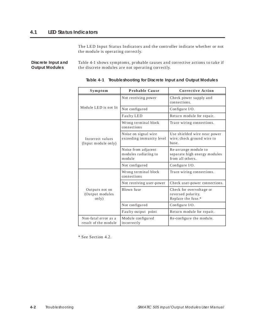
Troubleshooting4-2 SIMATIC 505 Input/Output Modules User Manual
4.1 LED Status Indicators
The LED Input Status Indicators and the controller indicate whether or notthe module is operating correctly.
Table 4-1 shows symptoms, probable causes and corrective actions to take ifthe discrete modules are not operating correctly.
Table 4-1 Troubleshooting for Discrete Input and Output Modules
Symptom Probable Cause Corrective Action
Module LED is not lit
Not receiving power Check power supply andconnections.
Module LED is not lit Not configured Configure I/O.
Faulty LED Return module for repair.
Wrong terminal blockconnections
Trace wiring connections.
Incorrect values(Input module only)
Noise on signal wireexceeding immunity level
Use shielded wire near powerwire; check ground wire tobase.(Input module only)
Noise from adjacentmodules radiating tomodule
Re-arrange module toseparate high energy modulesfrom all others.
Not configured Configure I/O.
Wrong terminal blockconnections
Trace wiring connections.
Not receiving user-power Check user-power connections.
Outputs not on(Output modules
only)
Blown fuse Check for overvoltage orreversed polarity.Replace the fuse.*
Not configured Configure I/O.
Faulty output point Return module for repair.
Non-fatal error as aresult of the module
Module configuredincorrectly
Re-configure the module.
* See Section 4.2.
Discrete Input andOutput Modules
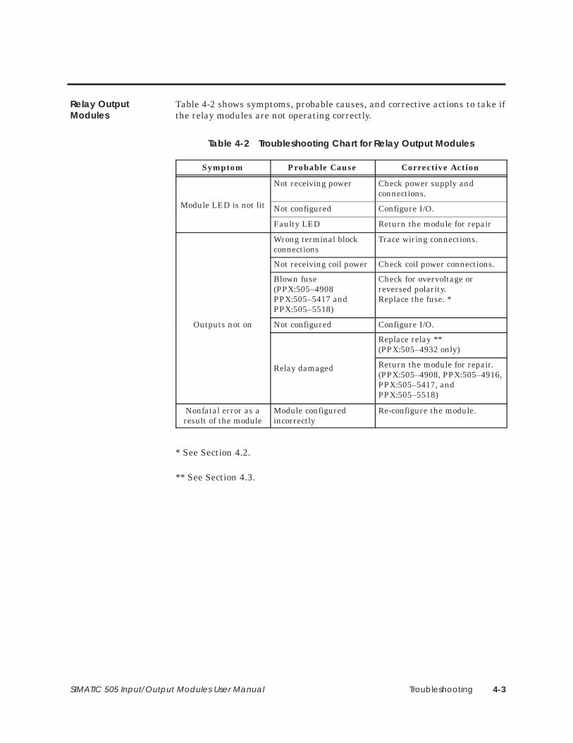
Troubleshooting 4-3SIMATIC 505 Input/Output Modules User Manual
Table 4-2 shows symptoms, probable causes, and corrective actions to take ifthe relay modules are not operating correctly.
Table 4-2 Troubleshooting Chart for Relay Output Modules
Symptom Probable Cause Corrective Action
Module LED is not lit
Not receiving power Check power supply andconnections.
Module LED is not lit Not configured Configure I/O.
Faulty LED Return the module for repair
Wrong terminal blockconnections
Trace wiring connections.
Not receiving coil power Check coil power connections.
Blown fuse(PPX:505–4908PPX:505–5417 andPPX:505–5518)
Check for overvoltage orreversed polarity.Replace the fuse. *
Outputs not on Not configured Configure I/O.
Replace relay **(PPX:505–4932 only)
Relay damaged Return the module for repair.(PPX:505–4908, PPX:505–4916,PPX:505–5417, andPPX:505–5518)
Nonfatal error as aresult of the module
Module configuredincorrectly
Re-configure the module.
* See Section 4.2.
** See Section 4.3.
Relay OutputModules

Troubleshooting4-4 SIMATIC 505 Input/Output Modules User Manual
LED Status Indicators (continued)
Table 4-3 shows symptoms, probable causes, and corrective actions to take ifthe word modules are not operating correctly.
Table 4-3 Troubleshooting Chart for Word Input and Output Modules
Symptom Probable Cause Corrective Action
Not receiving user-power Check user-power supply andconnections.
Module LED is not lit
Not receiving powerfrom base
Check power to base.
Module LED is not litBlown fuse Check for overvoltage or
reversed polarity.Replace the fuse. *
Faulty LED Return module for repair.
Connections wrong Trace wiring connections.
Signal wire noise Use shielded wire near powerwire.
Not configured Configure I/O.
Wrong jumpers selected Check jumpers.
Incorrect readings Signal timingrequirements not met(Input modules only)
Check signal timing at theterminal block.
Noise from adjacentmodules radiating tomodule
Re-arrange module toseparate high energy modulesfrom all others.
Nonfatal error as aresult of the module
Module has failed Take actions under LED is notlit, above. If this does notcorrect the problem, returnthe module for repair.
* See Section 4.2.
If you have difficulty with your system, contact the Siemens Energy &Automation, Inc., Technical Services Group in the U.S.A. at 423–461–2522.Outside the U.S.A., call 49–911–895–7000
Word Input andOutput Modules
If You Need Help
Troubleshooting 4-5SIMATIC 505 Input/Output Modules User Manual
4.2 Replacing a Fuse
If you have determined that your module has a blown fuse, follow theinstructions below to replace it.
Disable all power to the module and base before replacing a fuse.Failure to do so could result in injury to personnel or damage toequipment.
1. Disable all power to module and base.
2. Disconnect the terminal block from the module.
3. Use a flat-head screwdriver to loosen the screws at the top and bottomof the bezel.
4. Hold the top and bottom of the bezel, and slide the module carefully outof the slot (or slots for double-wide modules). There will be a slightresistance before the base backplane connectors separate.
5. Replace the blown fuse on the printed circuit board.
6. Insert the module into the base. (See Section 3.1.)
7. Power up the system.
If replacing the fuse does not correct the problem, check for other causes. Ifyou still cannot correct the problem, contact the Siemens Energy &Automation, Inc., Technical Services Group in the U.S.A. at 423–461–2522.Outside the U.S.A., call 49–911–895–7000
Discrete Output,Relay Output, WordInput and WordOutput Modules
WARNING!
If You Need Help
Troubleshooting4-6 SIMATIC 505 Input/Output Modules User Manual
4.3 Replacing a Relay
The 8-point and 16-point relay modules do not have replaceable relays. Ifyou have determined that one of the relays is the problem, contact yourdistributor. The 32-point relay module (PPX:505–4932) is equipped withreplaceable relays, one for each point. When a relay is bad, the LEDindicator continues functioning normally, since the indicators read from thelogic side of the PLC. However, the output device does not operate.
Disable all power to the module and base before replacing a relay.Failure to do so could result in injury to personnel, or damage toequipment.
To replace a damaged relay follow the instructions below.
1. Disable all power to module and base.
2. Disconnect the terminal block from the module.
3. Use a flat-head screwdriver to loosen the screws at the top and bottomof the bezel.
4. Hold the top and bottom of the bezel, and slide the module carefully outof the slot (or slots for double-wide modules). There will be a slightresistance before the base backplane connectors separate.
5. Using an ohmmeter, locate the damaged relay. Note its orientation.
6. Grasp the damaged relay at the top, and gently rock it from side to sideuntil the relay is loosened from the socket. Do not pry or apply force.You could break off one of the relay prongs inside the socket.
7. Insert a new relay (PPX:2586289–0001) as shown in Figure 4-1, withthe same orientation as the damaged relay.
8. Insert the module into the base. (See Section 3.1.)
9. Power up the system.
Relay OutputModules
WARNING!
Replacing aDamaged Relay
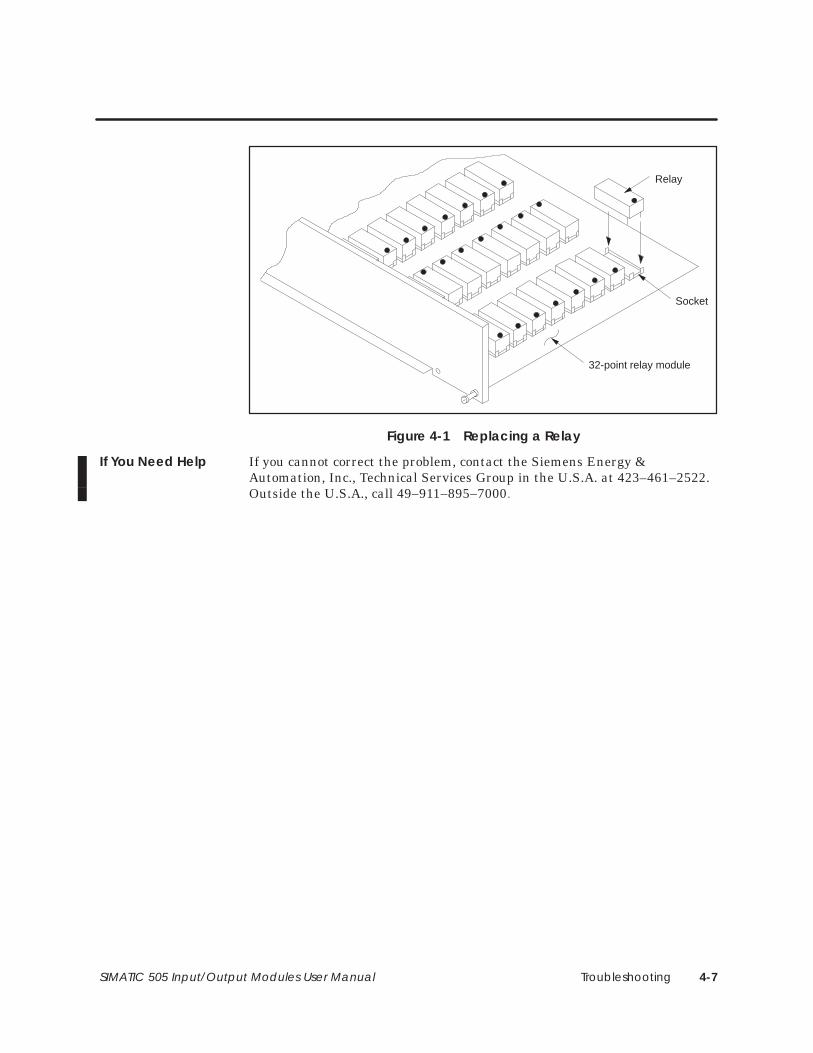
Troubleshooting 4-7SIMATIC 505 Input/Output Modules User Manual
Relay
Socket
32-point relay module
Figure 4-1 Replacing a Relay
If you cannot correct the problem, contact the Siemens Energy &Automation, Inc., Technical Services Group in the U.S.A. at 423–461–2522.Outside the U.S.A., call 49–911–895–7000
If You Need Help
Specifications A-1SIMATIC 505 Input/Output Modules User Manual
Appendix A
Specifications
A.1 Environmental Specifications A-2. . . . . . . . . . . . . . . . . . . . . . . . . . . . . . . . . . . . . . . . . . . . . . . . . . . .
A.2 Electrical Specifications A-3. . . . . . . . . . . . . . . . . . . . . . . . . . . . . . . . . . . . . . . . . . . . . . . . . . . . . . . . . Discrete Input Modules A-3. . . . . . . . . . . . . . . . . . . . . . . . . . . . . . . . . . . . . . . . . . . . . . . . . . . . . . . . . . Discrete Output Modules A-9. . . . . . . . . . . . . . . . . . . . . . . . . . . . . . . . . . . . . . . . . . . . . . . . . . . . . . . . Relay Output Modules A-17. . . . . . . . . . . . . . . . . . . . . . . . . . . . . . . . . . . . . . . . . . . . . . . . . . . . . . . . . . Word Input Module A-21. . . . . . . . . . . . . . . . . . . . . . . . . . . . . . . . . . . . . . . . . . . . . . . . . . . . . . . . . . . . . Word Output Module A-22. . . . . . . . . . . . . . . . . . . . . . . . . . . . . . . . . . . . . . . . . . . . . . . . . . . . . . . . . . . I/O Simulators A-23. . . . . . . . . . . . . . . . . . . . . . . . . . . . . . . . . . . . . . . . . . . . . . . . . . . . . . . . . . . . . . . . . . .
A.3 Terminal Block Worksheet A-24. . . . . . . . . . . . . . . . . . . . . . . . . . . . . . . . . . . . . . . . . . . . . . . . . . . . . . .
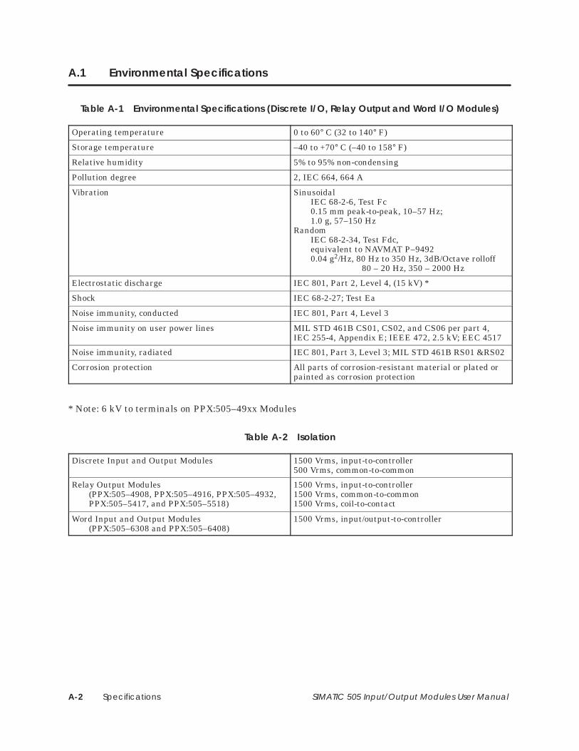
SpecificationsA-2 SIMATIC 505 Input/Output Modules User Manual
A.1 Environmental Specifications
Table A-1 Environmental Specifications (Discrete I/O, Relay Output and Word I/O Modules)
Operating temperature 0 to 60° C (32 to 140° F)
Storage temperature –40 to +70° C (–40 to 158° F)
Relative humidity 5% to 95% non-condensing
Pollution degree 2, IEC 664, 664 A
Vibration SinusoidalIEC 68-2-6, Test Fc0.15 mm peak-to-peak, 10–57 Hz;1.0 g, 57–150 Hz
RandomIEC 68-2-34, Test Fdc, equivalent to NAVMAT P–94920.04 g2/Hz, 80 Hz to 350 Hz, 3dB/Octave rolloff
80 – 20 Hz, 350 – 2000 Hz
Electrostatic discharge IEC 801, Part 2, Level 4, (15 kV) *
Shock IEC 68-2-27; Test Ea
Noise immunity, conducted IEC 801, Part 4, Level 3
Noise immunity on user power lines MIL STD 461B CS01, CS02, and CS06 per part 4, IEC 255-4, Appendix E; IEEE 472, 2.5 kV; EEC 4517
Noise immunity, radiated IEC 801, Part 3, Level 3; MIL STD 461B RS01 &RS02
Corrosion protection All parts of corrosion-resistant material or plated orpainted as corrosion protection
* Note: 6 kV to terminals on PPX:505–49xx Modules
Table A-2 Isolation
Discrete Input and Output Modules 1500 Vrms, input-to-controller500 Vrms, common-to-common
Relay Output Modules (PPX:505–4908, PPX:505–4916, PPX:505–4932,PPX:505–5417, and PPX:505–5518)
1500 Vrms, input-to-controller1500 Vrms, common-to-common1500 Vrms, coil-to-contact
Word Input and Output Modules(PPX:505–6308 and PPX:505–6408)
1500 Vrms, input/output-to-controller
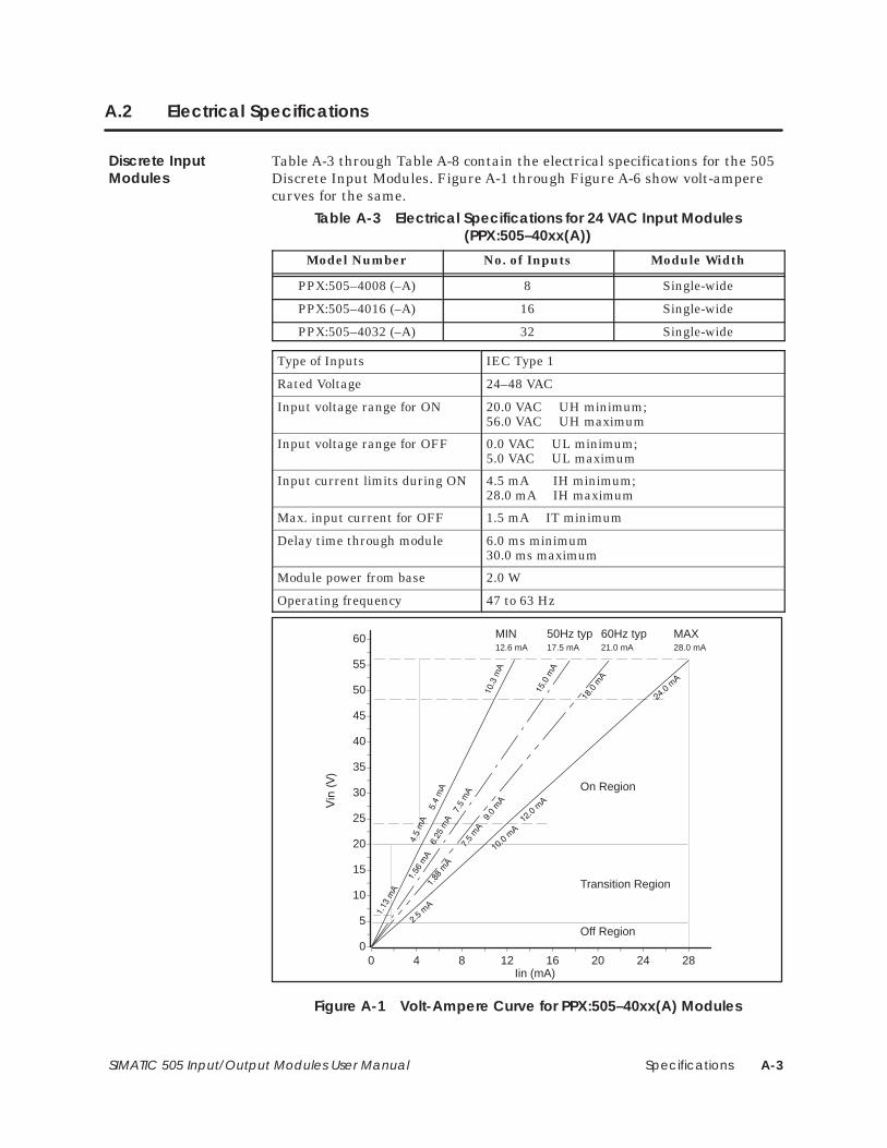
Specifications A-3SIMATIC 505 Input/Output Modules User Manual
A.2 Electrical Specifications
Table A-3 through Table A-8 contain the electrical specifications for the 505Discrete Input Modules. Figure A-1 through Figure A-6 show volt-amperecurves for the same.
Table A-3 Electrical Specifications for 24 VAC Input Modules(PPX:505–40xx(A))
Model Number No. of Inputs Module Width
PPX:505–4008 (–A) 8 Single-wide
PPX:505–4016 (–A) 16 Single-wide
PPX:505–4032 (–A) 32 Single-wide
Type of Inputs IEC Type 1
Rated Voltage 24–48 VAC
Input voltage range for ON 20.0 VAC UH minimum; 56.0 VAC UH maximum
Input voltage range for OFF 0.0 VAC UL minimum; 5.0 VAC UL maximum
Input current limits during ON 4.5 mA IH minimum;28.0 mA IH maximum
Max. input current for OFF 1.5 mA IT minimum
Delay time through module 6.0 ms minimum30.0 ms maximum
Module power from base 2.0 W
Operating frequency 47 to 63 Hz
0
5
10
15
20
25
30
35
40
45
50
55
60
0 4 8 12 16 20 24 28
MIN12.6 mA
MAX28.0 mA
50Hz typ17.5 mA
60Hz typ21.0 mA
Iin (mA)
Off Region
Transition Region
On Region
Figure A-1 Volt-Ampere Curve for PPX:505–40xx(A) Modules
Discrete InputModules
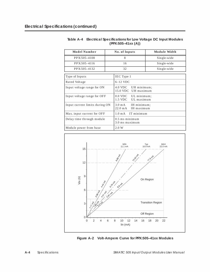
SpecificationsA-4 SIMATIC 505 Input/Output Modules User Manual
Electrical Specifications (continued)
Table A-4 Electrical Specifications for Low Voltage DC Input Modules(PPX:505–41xx (A))
Model Number No. of Inputs Module Width
PPX:505–4108 8 Single-wide
PPX:505–4116 16 Single-wide
PPX:505–4132 32 Single-wide
Type of Inputs IEC Type 1
Rated Voltage 6–12 VDC
Input voltage range for ON 4.0 VDC UH minimum; 15.0 VDC UH maximum
Input voltage range for OFF 0.0 VDC UL minimum; 1.5 VDC UL maximum
Input current limits during ON 3.0 mA IH minimum;22.0 mA IH maximum
Max. input current for OFF 1.0 mA IT minimum
Delay time through module 0.5 ms minimum3.0 ms maximum
Module power from base 2.0 W
0
3
6
9
12
15
0 2 4 6 8 10 12 14 16 18 20 22
MIN11.1 mA
MAX22.0 mA
Typ16.9 mA
lin (mA)
Off Region
Transition Region
On Region
Figure A-2 Volt-Ampere Curve for PPX:505–41xx Modules
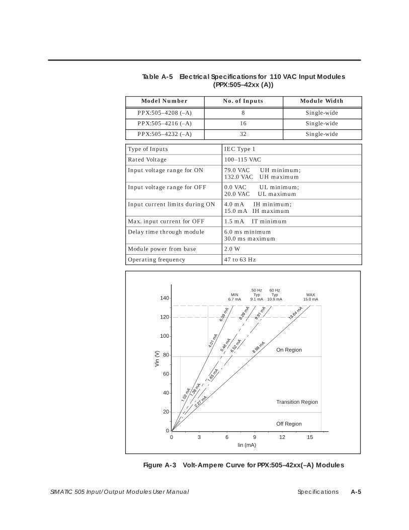
Specifications A-5SIMATIC 505 Input/Output Modules User Manual
Table A-5 Electrical Specifications for 110 VAC Input Modules(PPX:505–42xx (A))
Model Number No. of Inputs Module Width
PPX:505–4208 (–A) 8 Single-wide
PPX:505–4216 (–A) 16 Single-wide
PPX:505–4232 (–A) 32 Single-wide
Type of Inputs IEC Type 1
Rated Voltage 100–115 VAC
Input voltage range for ON 79.0 VAC UH minimum; 132.0 VAC UH maximum
Input voltage range for OFF 0.0 VAC UL minimum; 20.0 VAC UL maximum
Input current limits during ON 4.0 mA IH minimum;15.0 mA IH maximum
Max. input current for OFF 1.5 mA IT minimum
Delay time through module 6.0 ms minimum30.0 ms maximum
Module power from base 2.0 W
Operating frequency 47 to 63 Hz
0
20
40
60
80
100
120
140
0 3 6 9 12 15
MIN6.7 mA
MAX15.0 mA
50 HzTyp
9.1 mA
lin (mA)
Off Region
Transition Region
On Region
60 HzTyp
10.9 mA
Figure A-3 Volt-Ampere Curve for PPX:505–42xx(–A) Modules
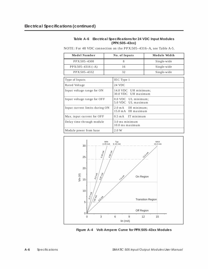
SpecificationsA-6 SIMATIC 505 Input/Output Modules User Manual
Electrical Specifications (continued)
Table A-6 Electrical Specifications for 24 VDC Input Modules(PPX:505–43xx)
NOTE: For 48 VDC connection on the PPX:505–4316–A, see Table A-5.
Model Number No. of Inputs Module Width
PPX:505–4308 8 Single-wide
PPX:505–4316 (–A) 16 Single-wide
PPX:505–4332 32 Single-wide
Type of Inputs IEC Type 1
Rated Voltage 24 VDC
Input voltage range for ON 14.0 VDC UH minimum; 30.0 VDC UH maximum
Input voltage range for OFF 0.0 VDC UL minimum; 5.0 VDC UL maximum
Input current limits during ON 2.0 mA IH minimum;15.0 mA IH maximum
Max. input current for OFF 0.5 mA IT minimum
Delay time through module 3.0 ms minimum10.0 ms maximum
Module power from base 2.0 W
0
5
10
15
20
25
30
0 3 6 9 12 15
MIN4.29 mA
MAX15.0 mA
Typ6.15 mA
lin (mA)
Off Region
Transition Region
On Region
Figure A-4 Volt-Ampere Curve for PPX:505–43xx Modules
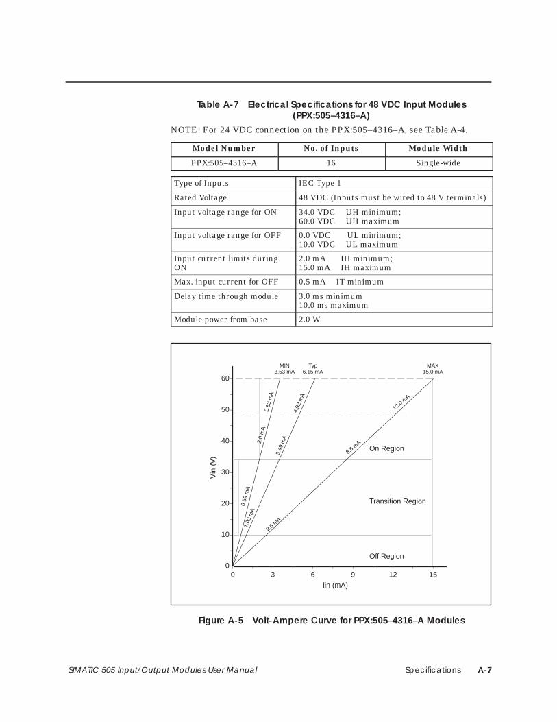
Specifications A-7SIMATIC 505 Input/Output Modules User Manual
Table A-7 Electrical Specifications for 48 VDC Input Modules(PPX:505–4316–A)
NOTE: For 24 VDC connection on the PPX:505–4316–A, see Table A-4.
Model Number No. of Inputs Module Width
PPX:505–4316–A 16 Single-wide
Type of Inputs IEC Type 1
Rated Voltage 48 VDC (Inputs must be wired to 48 V terminals)
Input voltage range for ON 34.0 VDC UH minimum; 60.0 VDC UH maximum
Input voltage range for OFF 0.0 VDC UL minimum; 10.0 VDC UL maximum
Input current limits duringON
2.0 mA IH minimum;15.0 mA IH maximum
Max. input current for OFF 0.5 mA IT minimum
Delay time through module 3.0 ms minimum10.0 ms maximum
Module power from base 2.0 W
0
10
20
30
40
50
60
0 3 6 9 12 15
MIN3.53 mA
MAX15.0 mA
Typ6.15 mA
lin (mA)
Off Region
Transition Region
On Region
Figure A-5 Volt-Ampere Curve for PPX:505–4316–A Modules
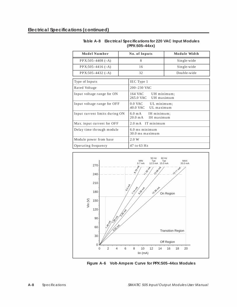
SpecificationsA-8 SIMATIC 505 Input/Output Modules User Manual
Electrical Specifications (continued)
Table A-8 Electrical Specifications for 220 VAC Input Modules(PPX:505–44xx)
Model Number No. of Inputs Module Width
PPX:505–4408 (–A) 8 Single-wide
PPX:505–4416 (–A) 16 Single-wide
PPX:505–4432 (–A) 32 Double-wide
Type of Inputs IEC Type 1
Rated Voltage 200–230 VAC
Input voltage range for ON 164 VAC UH minimum; 265.0 VAC UH maximum
Input voltage range for OFF 0.0 VAC UL minimum; 40.0 VAC UL maximum
Input current limits during ON 6.0 mA IH minimum;20.0 mA IH maximum
Max. input current for OFF 2.0 mA IT minimum
Delay time through module 6.0 ms minimum30.0 ms maximum
Module power from base 2.0 W
Operating frequency 47 to 63 Hz
0
30
60
90
120
150
180
210
240
270
0 2 4 6 8 10 12 14 16 18 20
MIN9.7 mA
MAX20.0 mA
50 HzTyp
12.5 mA
lin (mA)
Off Region
Transition Region
On Region
60 HzTyp
15.0 mA
Figure A-6 Volt-Ampere Curve for PPX:505–44xx Modules
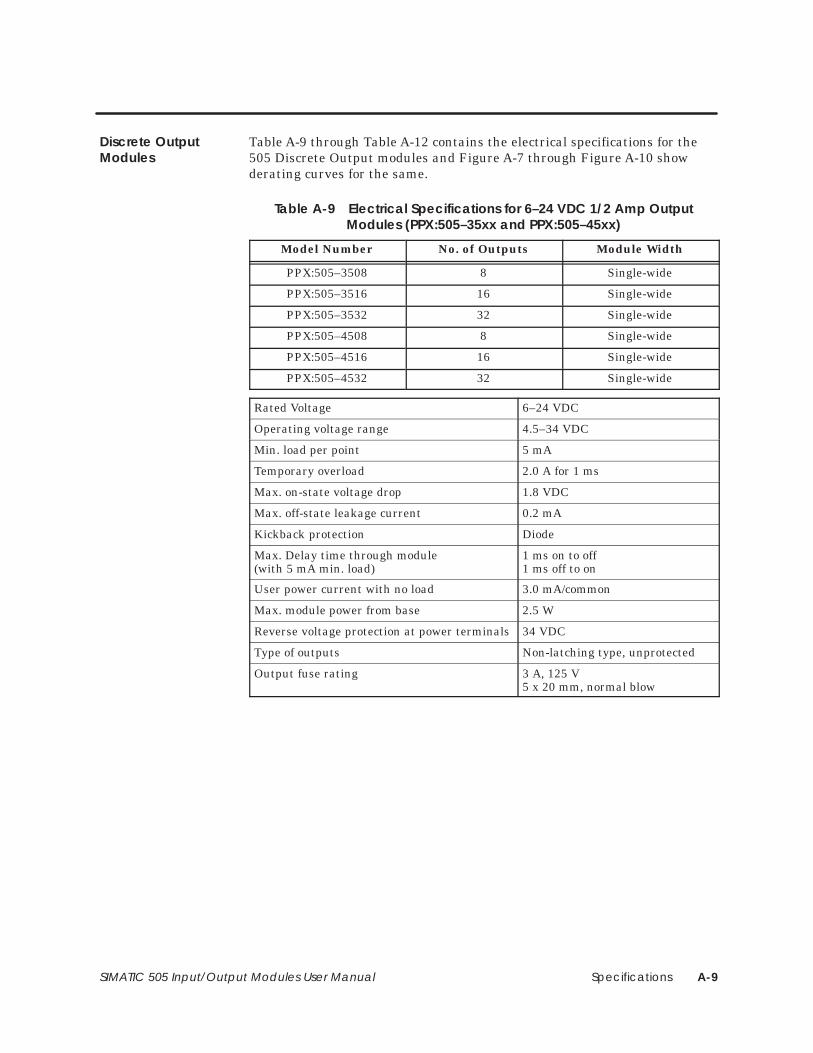
Specifications A-9SIMATIC 505 Input/Output Modules User Manual
Table A-9 through Table A-12 contains the electrical specifications for the505 Discrete Output modules and Figure A-7 through Figure A-10 showderating curves for the same.
Table A-9 Electrical Specifications for 6–24 VDC 1/2 Amp OutputModules (PPX:505–35xx and PPX:505–45xx)
Model Number No. of Outputs Module Width
PPX:505–3508 8 Single-wide
PPX:505–3516 16 Single-wide
PPX:505–3532 32 Single-wide
PPX:505–4508 8 Single-wide
PPX:505–4516 16 Single-wide
PPX:505–4532 32 Single-wide
Rated Voltage 6–24 VDC
Operating voltage range 4.5–34 VDC
Min. load per point 5 mA
Temporary overload 2.0 A for 1 ms
Max. on-state voltage drop 1.8 VDC
Max. off-state leakage current 0.2 mA
Kickback protection Diode
Max. Delay time through module(with 5 mA min. load)
1 ms on to off1 ms off to on
User power current with no load 3.0 mA/common
Max. module power from base 2.5 W
Reverse voltage protection at power terminals 34 VDC
Type of outputs Non-latching type, unprotected
Output fuse rating 3 A, 125 V5 x 20 mm, normal blow
Discrete OutputModules
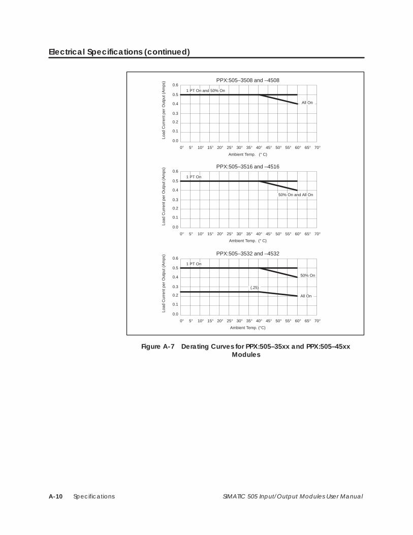
SpecificationsA-10 SIMATIC 505 Input/Output Modules User Manual
Electrical Specifications (continued)
0.6
0.5
0.4
0.3
0.2
0.1
0.0
0° 5° 10° 15° 20° 25° 30° 35° 40° 45° 50° 55° 60° 65° 70°
PPX:505–3508 and –4508
1 PT On and 50% On
Load
Cur
rent
per
Out
put (
Am
ps)
0.6
0.5
0.4
0.3
0.2
0.1
0.0
0° 5° 10° 15° 20° 25° 30° 35° 40° 45° 50° 55° 60° 65° 70°
PPX:505–3516 and –4516
1 PT On
50% On and All On
Load
Cur
rent
per
Out
put (
Am
ps)
0.6
0.5
0.4
0.3
0.2
0.1
0.0
0° 5° 10° 15° 20° 25° 30° 35° 40° 45° 50° 55° 60° 65° 70°
PPX:505–3532 and –4532
1 PT On
50% On
Load
Cur
rent
per
Out
put (
Am
ps)
Ambient Temp. (° C)
Ambient Temp. (° C)
Ambient Temp. (°C)
All On
All On
(.25)
Figure A-7 Derating Curves for PPX:505–35xx and PPX:505–45xxModules
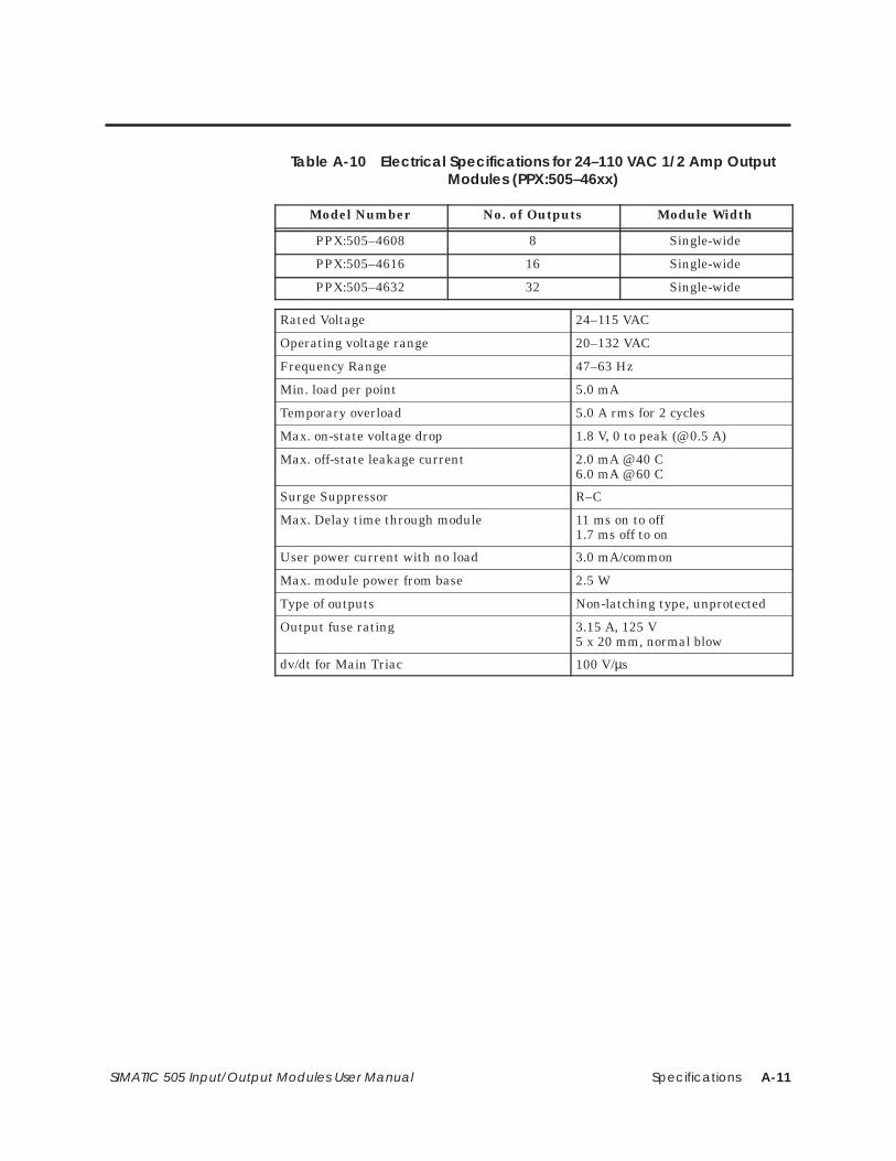
Specifications A-11SIMATIC 505 Input/Output Modules User Manual
Table A-10 Electrical Specifications for 24–110 VAC 1/2 Amp OutputModules (PPX:505–46xx)
Model Number No. of Outputs Module Width
PPX:505–4608 8 Single-wide
PPX:505–4616 16 Single-wide
PPX:505–4632 32 Single-wide
Rated Voltage 24–115 VAC
Operating voltage range 20–132 VAC
Frequency Range 47–63 Hz
Min. load per point 5.0 mA
Temporary overload 5.0 A rms for 2 cycles
Max. on-state voltage drop 1.8 V, 0 to peak (@ 0.5 A)
Max. off-state leakage current 2.0 mA @ 40 C6.0 mA @ 60 C
Surge Suppressor R–C
Max. Delay time through module 11 ms on to off1.7 ms off to on
User power current with no load 3.0 mA/common
Max. module power from base 2.5 W
Type of outputs Non-latching type, unprotected
Output fuse rating 3.15 A, 125 V5 x 20 mm, normal blow
dv/dt for Main Triac 100 V/µs
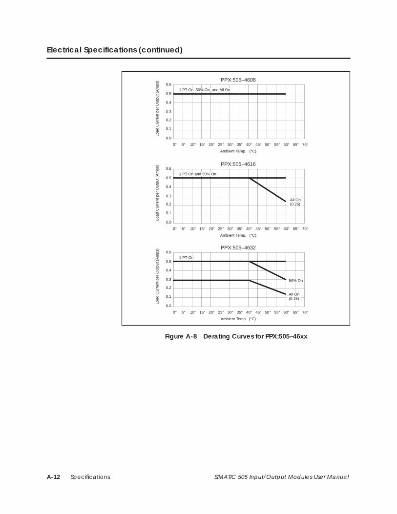
SpecificationsA-12 SIMATIC 505 Input/Output Modules User Manual
Electrical Specifications (continued)
0.6
0.5
0.4
0.3
0.2
0.1
0.0
0° 5° 10° 15° 20° 25° 30° 35° 40° 45° 50° 55° 60° 65° 70°
PPX:505–4608
1 PT On, 50% On, and All On
Load
Cur
rent
per
Out
put (
Am
ps)
0.6
0.5
0.4
0.3
0.2
0.1
0.0
0° 5° 10° 15° 20° 25° 30° 35° 40° 45° 50° 55° 60° 65° 70°
PPX:505–4616
1 PT On and 50% On
All On(0.25)
Load
Cur
rent
per
Out
put (
Am
ps)
0.6
0.5
0.4
0.3
0.2
0.1
0.0
0° 5° 10° 15° 20° 25° 30° 35° 40° 45° 50° 55° 60° 65° 70°
PPX:505–4632
1 PT On
50% On
Load
Cur
rent
per
Out
put (
Am
ps)
Ambient Temp. (°C)
Ambient Temp. (°C)
Ambient Temp. (°C)
All On(0.15)
Figure A-8 Derating Curves for PPX:505–46xx
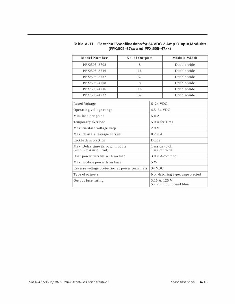
Specifications A-13SIMATIC 505 Input/Output Modules User Manual
Table A-11 Electrical Specifications for 24 VDC 2 Amp Output Modules(PPX:505–37xx and PPX:505–47xx)
Model Number No. of Outputs Module Width
PPX:505–3708 8 Double-wide
PPX:505–3716 16 Double-wide
PPX:505–3732 32 Double-wide
PPX:505–4708 8 Double-wide
PPX:505–4716 16 Double-wide
PPX:505–4732 32 Double-wide
Rated Voltage 6–24 VDC
Operating voltage range 4.5–34 VDC
Min. load per point 5 mA
Temporary overload 5.0 A for 1 ms
Max. on-state voltage drop 2.0 V
Max. off-state leakage current 0.2 mA
Kickback protection Diode
Max. Delay time through module(with 5 mA min. load)
1 ms on to off1 ms off to on
User power current with no load 3.0 mA/common
Max. module power from base 5 W
Reverse voltage protection at power terminals 34 VDC
Type of outputs Non-latching type, unprotected
Output fuse rating 3.15 A, 125 V5 x 20 mm, normal blow
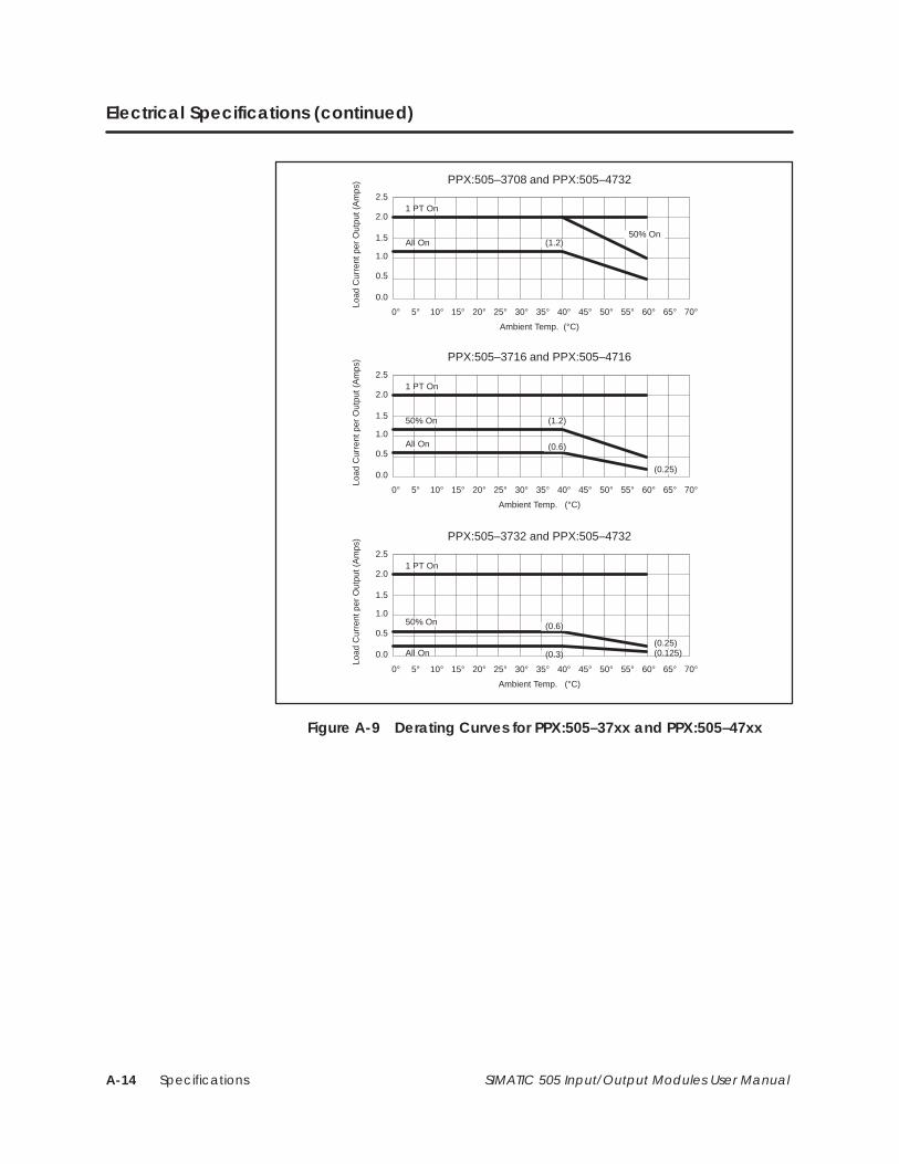
SpecificationsA-14 SIMATIC 505 Input/Output Modules User Manual
Electrical Specifications (continued)
2.5
2.0
1.5
1.0
0.5
0.0
0° 5° 10° 15° 20° 25° 30° 35° 40° 45° 50° 55° 60° 65° 70°
PPX:505–3708 and PPX:505–4732
1 PT On
Load
Cur
rent
per
Out
put (
Am
ps)
PPX:505–3716 and PPX:505–4716
PPX:505–3732 and PPX:505–4732
Ambient Temp. (°C)
All On (1.2)50% On
2.5
2.0
1.5
1.0
0.5
0.0
0° 5° 10° 15° 20° 25° 30° 35° 40° 45° 50° 55° 60° 65° 70°
1 PT On
Load
Cur
rent
per
Out
put (
Am
ps)
Ambient Temp. (°C)
50% On (1.2)
All On (0.6)
(0.25)
2.5
2.0
1.5
1.0
0.5
0.0
0° 5° 10° 15° 20° 25° 30° 35° 40° 45° 50° 55° 60° 65° 70°
1 PT On
Load
Cur
rent
per
Out
put (
Am
ps)
Ambient Temp. (°C)
50% On
(0.3)All On
(0.6)
(0.25)(0.125)
Figure A-9 Derating Curves for PPX:505–37xx and PPX:505–47xx

Specifications A-15SIMATIC 505 Input/Output Modules User Manual
Table A-12 Electrical Specifications for 110–220 VAC 2 Amp OutputModules (PPX:505–48xx)
Model Number No. of Outputs Module Width
PPX:505–4808 8 Double-wide
PPX:505–4816 16 Double-wide
PPX:505–4832 32 Double-wide
Rated Voltage 100–230 VAC
Operating voltage range 85–265 VAC
Frequency Range 47–63 Hz
Min. load per point 50.0 mA
Temporary overload 20.0 A rms for 2 cycles
Max. on-state voltage drop 2.0 V, 0 to peak, (@ 2 A)
Max. off-state leakage current 6.0 mA
Max. Delay time through module 11 ms on to off; 2 ms off to on
Frequency range 47 to 63 Hz
Max. module power from base 5 W
Surge Suppressor R–C
Type of outputs Non-latching type, unprotected
Output fuse rating 5.0 A, 250 V0.25 x 1.25 in., normal blow
dv/dt for Main Triac 100 V/us
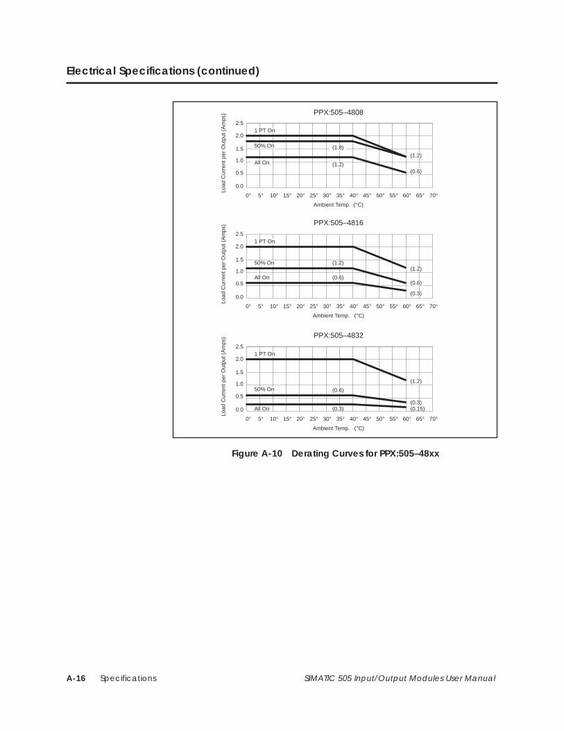
SpecificationsA-16 SIMATIC 505 Input/Output Modules User Manual
Electrical Specifications (continued)
2.5
2.0
1.5
1.0
0.5
0.0
0° 5° 10° 15° 20° 25° 30° 35° 40° 45° 50° 55° 60° 65° 70°
PPX:505–4808
1 PT On
Load
Cur
rent
per
Out
put (
Am
ps)
PPX:505–4816
PPX:505–4832
Ambient Temp. (°C)
All On
(1.8)(1.2)
2.5
2.0
1.5
1.0
0.5
0.0
0° 5° 10° 15° 20° 25° 30° 35° 40° 45° 50° 55° 60° 65° 70°
1 PT On
Load
Cur
rent
per
Out
put (
Am
ps)
Ambient Temp. (°C)
50% On (1.2)
All On (0.6)
(0.3)
2.5
2.0
1.5
1.0
0.5
0.0
0° 5° 10° 15° 20° 25° 30° 35° 40° 45° 50° 55° 60° 65° 70°
1 PT On
Load
Cur
rent
per
Out
put (
Am
ps)
Ambient Temp. (°C)
50% On
(0.3)All On
(0.6)
(0.3)(0.15)
(1.2)(0.6)
50% On
(0.6)
(1.2)
(1.2)
Figure A-10 Derating Curves for PPX:505–48xx
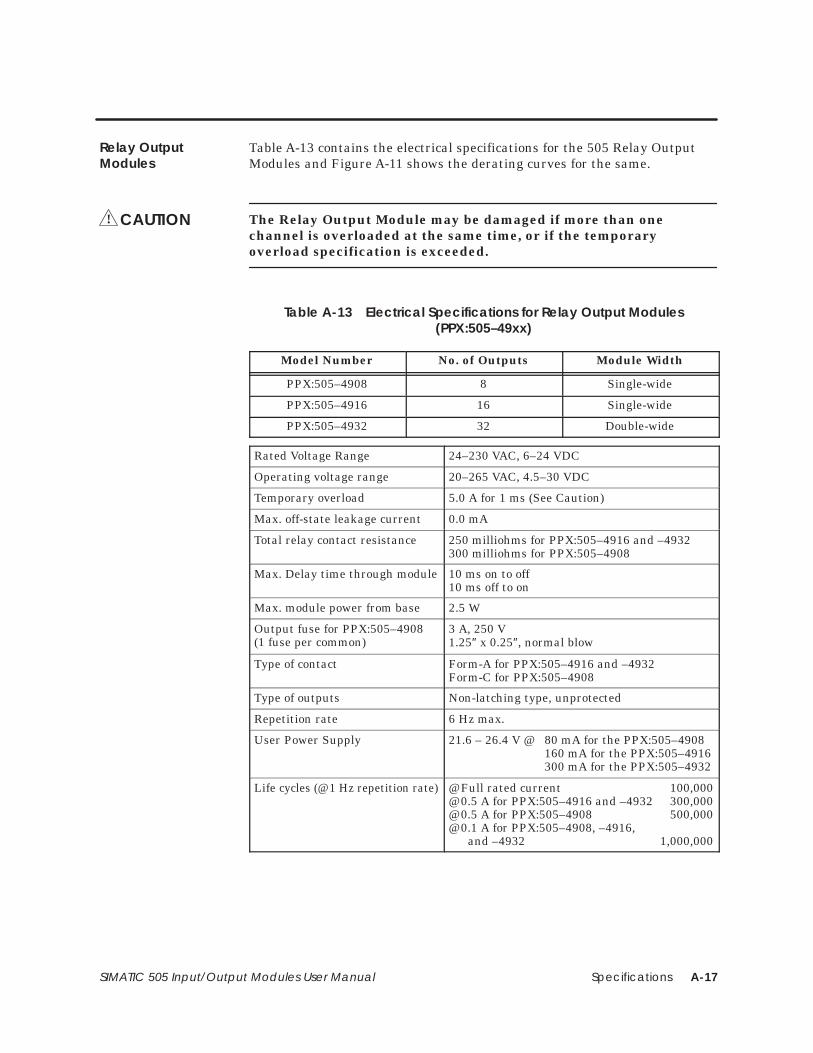
Specifications A-17SIMATIC 505 Input/Output Modules User Manual
Table A-13 contains the electrical specifications for the 505 Relay OutputModules and Figure A-11 shows the derating curves for the same.
The Relay Output Module may be damaged if more than onechannel is overloaded at the same time, or if the temporaryoverload specification is exceeded.
Table A-13 Electrical Specifications for Relay Output Modules(PPX:505–49xx)
Model Number No. of Outputs Module Width
PPX:505–4908 8 Single-wide
PPX:505–4916 16 Single-wide
PPX:505–4932 32 Double-wide
Rated Voltage Range 24–230 VAC, 6–24 VDC
Operating voltage range 20–265 VAC, 4.5–30 VDC
Temporary overload 5.0 A for 1 ms (See Caution)
Max. off-state leakage current 0.0 mA
Total relay contact resistance 250 milliohms for PPX:505–4916 and –4932300 milliohms for PPX:505–4908
Max. Delay time through module 10 ms on to off10 ms off to on
Max. module power from base 2.5 W
Output fuse for PPX:505–4908(1 fuse per common)
3 A, 250 V1.25″ x 0.25″, normal blow
Type of contact Form-A for PPX:505–4916 and –4932Form-C for PPX:505–4908
Type of outputs Non-latching type, unprotected
Repetition rate 6 Hz max.
User Power Supply 21.6 – 26.4 V @ 80 mA for the PPX:505–4908160 mA for the PPX:505–4916300 mA for the PPX:505–4932
Life cycles (@ 1 Hz repetition rate) @ Full rated current 100,000@ 0.5 A for PPX:505–4916 and –4932 300,000@ 0.5 A for PPX:505–4908 500,000@ 0.1 A for PPX:505–4908, –4916,
and –4932 1,000,000
Relay OutputModules
CAUTION!
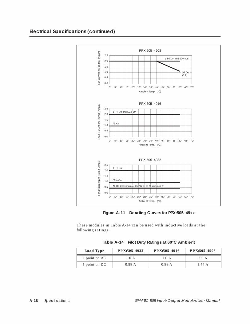
SpecificationsA-18 SIMATIC 505 Input/Output Modules User Manual
Electrical Specifications (continued)
2.5
2.0
1.5
1.0
0.5
0.0
0° 5° 10° 15° 20° 25° 30° 35° 40° 45° 50° 55° 60° 65° 70°
PPX:505–4908
1 PT On and 50% On
Load
Cur
rent
per
Out
put (
Am
ps)
PPX:505–4916
PPX:505–4932
Ambient Temp. (°C)
2.5
2.0
1.5
1.0
0.5
0.0
0° 5° 10° 15° 20° 25° 30° 35° 40° 45° 50° 55° 60° 65° 70°
1 PT On and 50% On
Load
Cur
rent
per
Out
put (
Am
ps)
Ambient Temp. (°C)
2.5
2.0
1.5
1.0
0.5
0.0
0° 5° 10° 15° 20° 25° 30° 35° 40° 45° 50° 55° 60° 65° 70°
1 PT On
Load
Cur
rent
per
Out
put (
Am
ps)
Ambient Temp. (°C)
50% On
All On (maximum of 25 Pts on at 60 degrees C)
All On(1.2)
All On
Figure A-11 Derating Curves for PPX:505–49xx
These modules in Table A-14 can be used with inductive loads at thefollowing ratings:
Table A-14 Pilot Duty Ratings at 60°C Ambient
Load Type PPX:505–4932 PPX:505–4916 PPX:505–4908
1 point on AC 1.0 A 1.0 A 2.0 A
1 point on DC 0.88 A 0.88 A 1.44 A
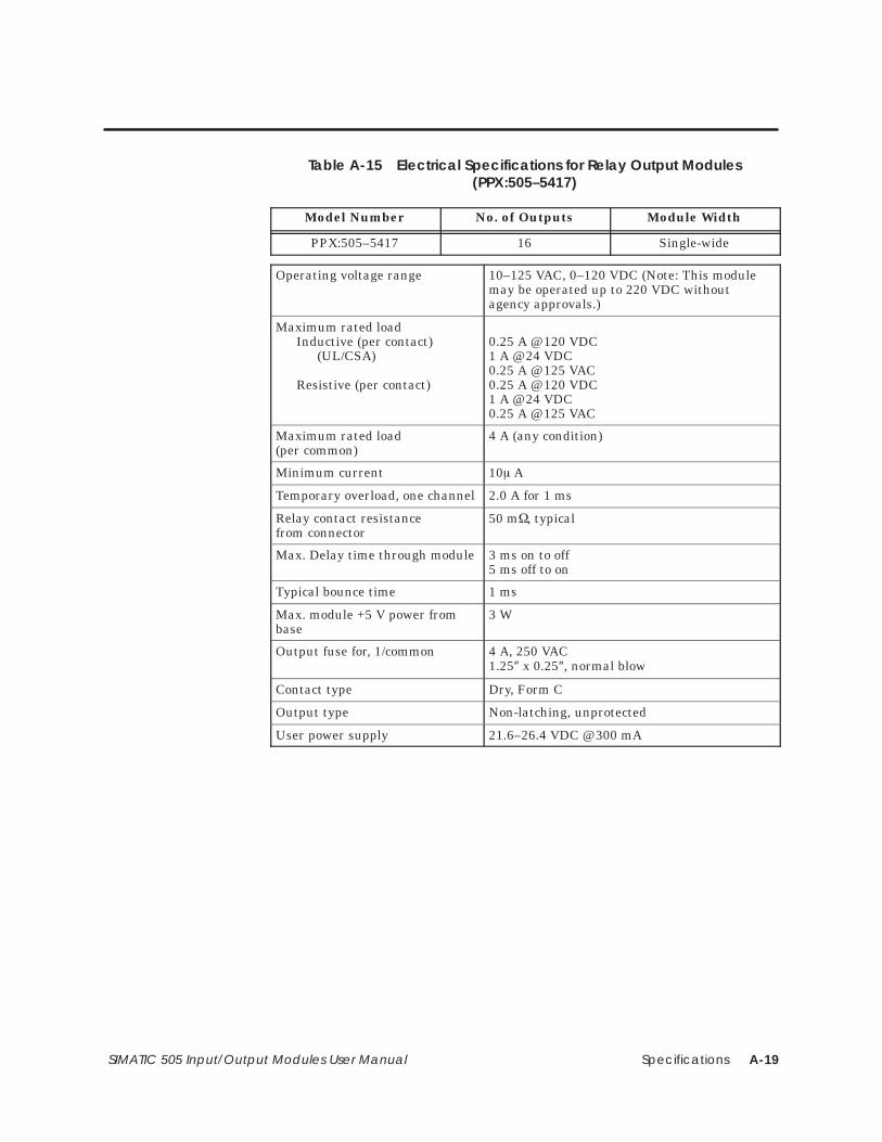
Specifications A-19SIMATIC 505 Input/Output Modules User Manual
Table A-15 Electrical Specifications for Relay Output Modules(PPX:505–5417)
Model Number No. of Outputs Module Width
PPX:505–5417 16 Single-wide
Operating voltage range 10–125 VAC, 0–120 VDC (Note: This modulemay be operated up to 220 VDC withoutagency approvals.)
Maximum rated loadInductive (per contact)
(UL/CSA)
Resistive (per contact)
0.25 A @ 120 VDC1 A @ 24 VDC0.25 A @ 125 VAC0.25 A @ 120 VDC1 A @ 24 VDC0.25 A @ 125 VAC
Maximum rated load(per common)
4 A (any condition)
Minimum current 10 A
Temporary overload, one channel 2.0 A for 1 ms
Relay contact resistancefrom connector
50 m, typical
Max. Delay time through module 3 ms on to off5 ms off to on
Typical bounce time 1 ms
Max. module +5 V power frombase
3 W
Output fuse for, 1/common 4 A, 250 VAC1.25″ x 0.25″, normal blow
Contact type Dry, Form C
Output type Non-latching, unprotected
User power supply 21.6–26.4 VDC @ 300 mA
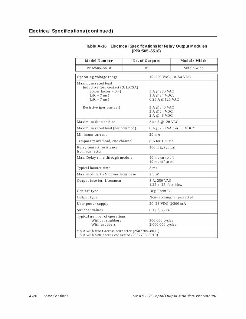
SpecificationsA-20 SIMATIC 505 Input/Output Modules User Manual
Electrical Specifications (continued)
Table A-16 Electrical Specifications for Relay Output Modules(PPX:505–5518)
Model Number No. of Outputs Module Width
PPX:505–5518 16 Single-wide
Operating voltage range 10–250 VAC, 10–54 VDC
Maximum rated loadInductive (per contact) (UL/CSA)
(power factor = 0.4)(L/R = 7 ms)(L/R = 7 ms)
Resistive (per contact)
5 A @ 250 VAC1 A @ 24 VDC; 0.25 A @ 125 VAC
5 A @ 240 VAC3 A @ 24 VDC2 A @ 48 VDC
Maximum Starter Size Size 5 @ 120 VAC
Maximum rated load (per common) 8 A @ 250 VAC or 30 VDC*
Minimum current 20 mA
Temporary overload, one channel 8 A for 100 ms
Relay contact resistancefrom connector
100 m, typical
Max. Delay time through module 10 ms on to off10 ms off to on
Typical bounce time 3 ms
Max. module +5 V power from base 2.5 W
Output fuse for, 1/common 8 A, 250 VAC1.25 x .25, fast blow
Contact type Dry, Form C
Output type Non-latching, unprotected
User power supply 20–28 VDC @ 200 mA
Snubber values 0.1 µf, 330 Ω
Typical number of operationsWithout snubbersWith snubbers
300,000 cycles2,000,000 cycles
* 8 A with front access connector (2587705–8011)5 A with side access connector (2587705–8010)
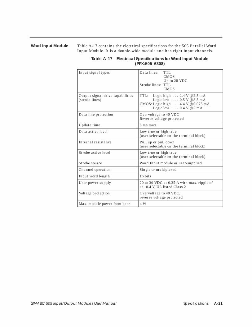
Specifications A-21SIMATIC 505 Input/Output Modules User Manual
Table A-17 contains the electrical specifications for the 505 Parallel WordInput Module. It is a double-wide module and has eight input channels.
Table A-17 Electrical Specifications for Word Input Module(PPX:505–6308)
Input signal types Data lines: TTLCMOSUp to 28 VDC
Strobe lines: TTLCMOS
Output signal drive capabilities(strobe lines)
TTL: Logic high 2.4 V @ 2.5 mA. . . Logic low 0.5 V @ 8.5 mA. . . .
CMOS: Logic high 4.4 V @ 0.075 mA. . . Logic low 0.4 V @ 2 mA. . . .
Data line protection Overvoltage to 40 VDCReverse voltage protected
Update time 8 ms max.
Data active level Low true or high true (user selectable on the terminal block)
Internal resistance Pull up or pull down(user selectable on the terminal block)
Strobe active level Low true or high true (user selectable on the terminal block)
Strobe source Word Input module or user-supplied
Channel operation Single or multiplexed
Input word length 16 bits
User power supply 20 to 30 VDC at 0.35 A with max. ripple of+/– 0.4 V, UL listed Class 2
Voltage protection Overvoltage to 40 VDC,reverse voltage protected
Max. module power from base 4 W
Word Input Module
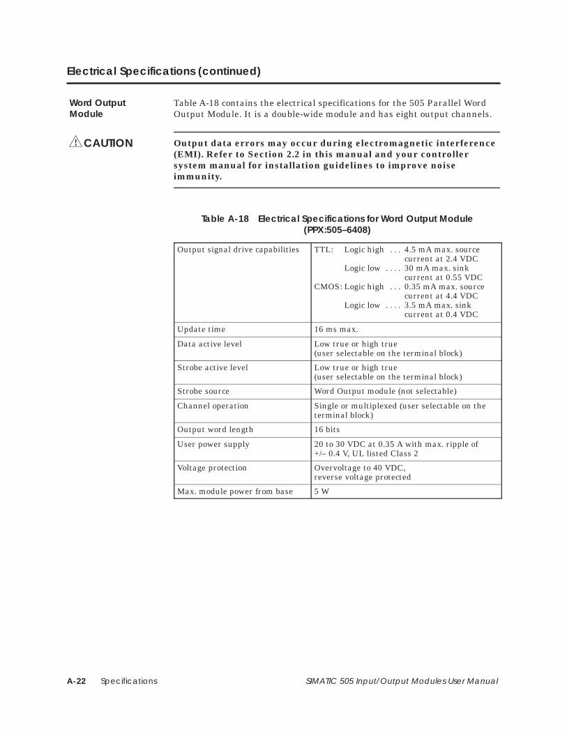
SpecificationsA-22 SIMATIC 505 Input/Output Modules User Manual
Electrical Specifications (continued)
Table A-18 contains the electrical specifications for the 505 Parallel WordOutput Module. It is a double-wide module and has eight output channels.
Output data errors may occur during electromagnetic interference(EMI). Refer to Section 2.2 in this manual and your controllersystem manual for installation guidelines to improve noiseimmunity.
Table A-18 Electrical Specifications for Word Output Module(PPX:505–6408)
Output signal drive capabilities TTL: Logic high 4.5 mA max. source. . . current at 2.4 VDC
Logic low 30 mA max. sink. . . . current at 0.55 VDC
CMOS: Logic high 0.35 mA max. source. . . current at 4.4 VDC
Logic low 3.5 mA max. sink. . . . current at 0.4 VDC
Update time 16 ms max.
Data active level Low true or high true (user selectable on the terminal block)
Strobe active level Low true or high true (user selectable on the terminal block)
Strobe source Word Output module (not selectable)
Channel operation Single or multiplexed (user selectable on theterminal block)
Output word length 16 bits
User power supply 20 to 30 VDC at 0.35 A with max. ripple of+/– 0.4 V, UL listed Class 2
Voltage protection Overvoltage to 40 VDC,reverse voltage protected
Max. module power from base 5 W
Word OutputModule
CAUTION!
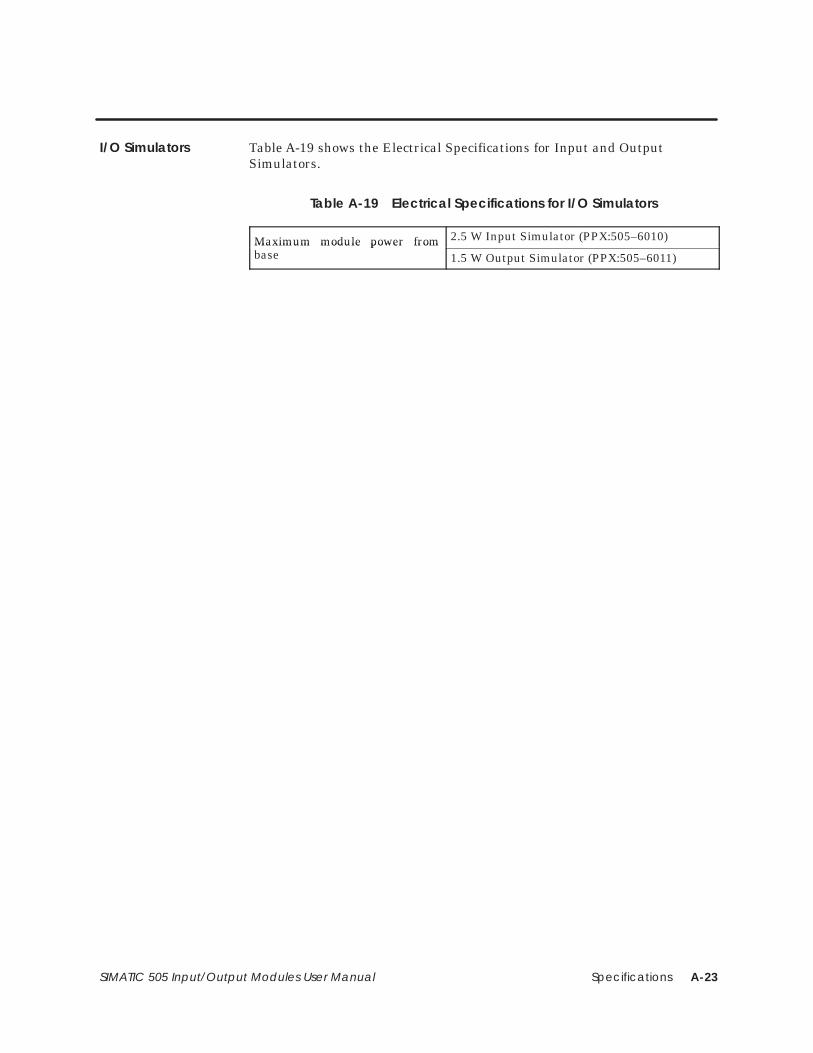
Specifications A-23SIMATIC 505 Input/Output Modules User Manual
Table A-19 shows the Electrical Specifications for Input and OutputSimulators.
Table A-19 Electrical Specifications for I/O Simulators
Maximum module power frombase
2.5 W Input Simulator (PPX:505–6010)Maximum module power frombase 1.5 W Output Simulator (PPX:505–6011)
I/O Simulators
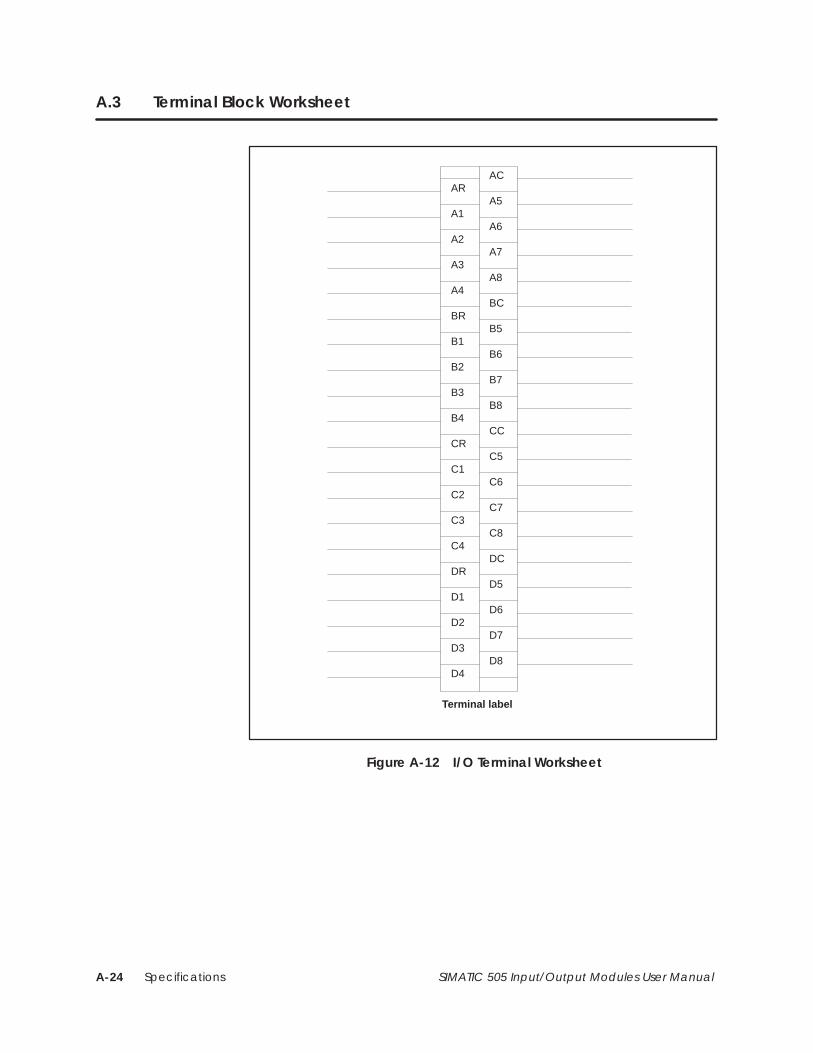
SpecificationsA-24 SIMATIC 505 Input/Output Modules User Manual
A.3 Terminal Block Worksheet
Terminal label
ACAR
A1
A2
A3
A4
BR
B1
B2
B3
B4
CR
C1
C2
C3
C4
DR
D1
D2
D3
D4
A5
A6
A7
A8
BC
B5
B6
B7
B8
CC
C5
C6
C7
C8
DC
D5
D6
D7
D8
Figure A-12 I/O Terminal Worksheet
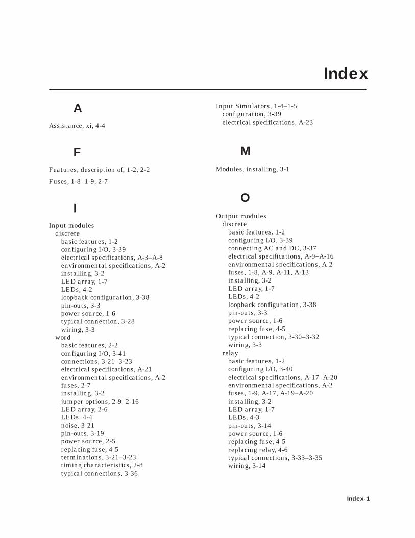
Index-1
Index
AAssistance, xi, 4-4
FFeatures, description of, 1-2, 2-2
Fuses, 1-8–1-9, 2-7
IInput modules
discretebasic features, 1-2configuring I/O, 3-39electrical specifications, A-3–A-8environmental specifications, A-2installing, 3-2LED array, 1-7LEDs, 4-2loopback configuration, 3-38pin-outs, 3-3power source, 1-6typical connection, 3-28wiring, 3-3
wordbasic features, 2-2configuring I/O, 3-41connections, 3-21–3-23electrical specifications, A-21environmental specifications, A-2fuses, 2-7installing, 3-2jumper options, 2-9–2-16LED array, 2-6LEDs, 4-4noise, 3-21pin-outs, 3-19power source, 2-5replacing fuse, 4-5terminations, 3-21–3-23timing characteristics, 2-8typical connections, 3-36
Input Simulators, 1-4–1-5configuration, 3-39electrical specifications, A-23
MModules, installing, 3-1
OOutput modules
discretebasic features, 1-2configuring I/O, 3-39connecting AC and DC, 3-37electrical specifications, A-9–A-16environmental specifications, A-2fuses, 1-8, A-9, A-11, A-13installing, 3-2LED array, 1-7LEDs, 4-2loopback configuration, 3-38pin-outs, 3-3power source, 1-6replacing fuse, 4-5typical connection, 3-30–3-32wiring, 3-3
relaybasic features, 1-2configuring I/O, 3-40electrical specifications, A-17–A-20environmental specifications, A-2fuses, 1-9, A-17, A-19–A-20installing, 3-2LED array, 1-7LEDs, 4-3pin-outs, 3-14power source, 1-6replacing fuse, 4-5replacing relay, 4-6typical connections, 3-33–3-35wiring, 3-14
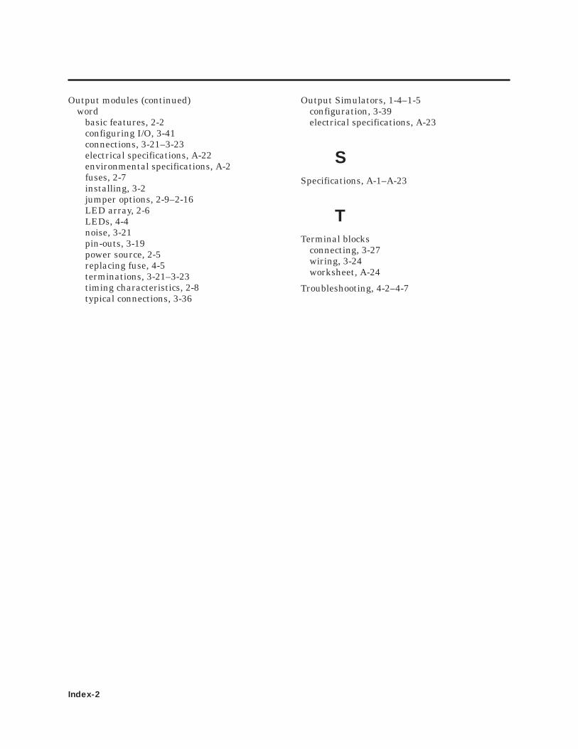
Index-2
Output modules (continued)word
basic features, 2-2configuring I/O, 3-41connections, 3-21–3-23electrical specifications, A-22environmental specifications, A-2fuses, 2-7installing, 3-2jumper options, 2-9–2-16LED array, 2-6LEDs, 4-4noise, 3-21pin-outs, 3-19power source, 2-5replacing fuse, 4-5terminations, 3-21–3-23timing characteristics, 2-8typical connections, 3-36
Output Simulators, 1-4–1-5configuration, 3-39electrical specifications, A-23
SSpecifications, A-1–A-23
TTerminal blocks
connecting, 3-27wiring, 3-24worksheet, A-24
Troubleshooting, 4-2–4-7

Customer Registration
We would like to know what you think about our user manuals so that we can serve you better.How would you rate the quality of our manuals?
Excellent Good Fair Poor
AccuracyOrganizationClarityCompletenessOverall designSizeIndex
Would you be interested in giving us more detailed comments about our manuals?
Yes! Please send me a questionnaire.
No. Thanks anyway.
Your Name:
Title:
Telephone Number: ( )
Company Name:
Company Address:
Manual Name: SIMATIC 505 Input/Output Modules User Manual Edition: Second
Manual Assembly Number: 2586546–0094 Date: 02/94
Order Number: PPX:505–8105–2
BUSINESS REPLY MAILFIRST CLASS PERMIT NO.3 JOHNSON CITY, TN
FOLD
FOLD
POSTAGE WILL BE PAID BY ADDRESSEE
NO POSTAGENECESSARYIF MAILED
IN THEUNITED STATES
ATTN TECHNICAL COMMUNICATIONS M/S 519SIEMENS ENERGY & AUTOMATION INC PO BOX 1255JOHNSON CITY TN 37605–1255
SIEMENS ENERGY & AUTOMATION INC 3000 BILL GARLAND ROADPO BOX 1255JOHNSON CITY TN 37605–1255

$ %# # " !$
#$ ! # %# #$ " !$ !#( ! &%" %"! !
!#%# #$ " !$ !#( ! &%" %"! !
!#'#%#$ "#%"#$ ! $ #$%# %# # " !#'#%#$ "#%"#$ !