Embed Size (px)
Citation preview

Appendix C Job Performance Measure Form ES-C-1 Worksheet
2016 Systems - Control Room JPM A (Rev_011116) NUREG 1021, Revision 10
SIM JPM A Developed By: ______________________________ Date: ___________ Instructor/Developer Concurred By: ______________________________ Date: ___________ Line Superintendent/Supervisor SRO Approved By: ______________________________ Date: ___________ Superintendent/Supervisor Training

Appendix C Page 2 of 22 Form ES-C-1 Job Performance Measure Worksheet
2016 Systems - Control Room JPM A NUREG 1021, Revision 10
Facility: HB Robinson Task No.: Task Title: Operation With High Switchyard
Voltage JPM No.: 2016 Systems - Control
Room JPM A (Alternate Path)
K/A Reference: 062 A2.08 (2.7/3.0) Examinee: NRC Examiner:
Facility Evaluator: Date:
Method of testing:
Simulated Performance: Actual Performance: X Classroom Simulator X Plant
READ TO THE EXAMINEE
I will explain the initial conditions, which steps to simulate or discuss, and provide initiating cues. When you complete the task successfully, the objective for this Job Performance Measure will be satisfied.
Provide operator with Initial Conditions/Cue (Last Page of this JPM), and Handout 1. Initial Conditions: • Plant is at 100% power. • Due to abnormal conditions on the Grid, 480V Bus E-2 currently
exceeds 505 Volts. • AOP-031, Operation with High Switchyard Voltage, has been
completed up to step 21. • You are the BOP. • “D” IAC is in service with “A” and “B” IACs in AUTO. • The DSDG is secured and aligned for AUTO. • The Load on Emergency Bus E-1 has NOT been altered since
entering this AOP. Initiating Cue: The CRS has directed you to continue with AOP-031 until 480V Bus E-2
voltage is restored to less than 505 Volts.

Appendix C Page 3 of 22 Form ES-C-1 Job Performance Measure Worksheet
2016 Systems - Control Room JPM A NUREG 1021, Revision 10
Task Standard: The operator will transfer 4KV Bus 4 & 5 from the UAT to the SUT (via 4KV Bus 3) in an effort to lower Switchyard Voltage; and when Breaker 50/20 fails to automatically OPEN, the operator will manually open it per AOP-31. Ultimately, the voltage on 480V Bus E-2 will be lowered to less than 502 volts.
Required Materials: None General References: AOP-031 (Operation with High Switchyard Voltage), Rev 15 OMM-022 (Emergency Operating Procedures User’s Guide), Rev 45 Handouts: Handout 1: Control Room Copy of AOP-031 marked up for this JPM to
Step 21. Time Critical Task: NO Validation Time: 11 minutes
Critical Step Justification
Step 21 This step is critical because inserting the synchroscope key into 4 KV TIES
Synchroscope Key Switch is necessary to transfer 4KV Bus 4 & 5 from the UAT to the SUT (via 4KV Bus 3).
Step 22 This step is critical because placing the Synchroscope Switch to the BUS 3 & 4 position is necessary to transfer 4KV Bus 4 & 5 from the UAT to the SUT (via 4KV Bus 3).
Step 24 This step is critical because momentarily placing the Control Switch for 4KV BUS 3-4 TIE, BKR 52/19 to the CLOSE position is necessary to transfer 4KV Bus 4 & 5 from the UAT to the SUT (via 4KV Bus 3).
Alternate Path Critical Step Justification
Step 27 This step is critical because depressing the THINK pushbutton and placing the
control switch for BKR 52/20 to the OPEN (TRIP) position is necessary to manually open Breaker 52/20.

Appendix C Page 4 of 22 Form ES-C-1 Job Performance Measure Worksheet
2016 Systems - Control Room JPM A NUREG 1021, Revision 10
SIMULATOR OPERATIONAL GUIDELINES 1. Construct Scenario File 006_JPM_ A as follows:
• ICO V4160B4BRK20 f:TRIP_FAIL, (Breaker 52/20 Fails to Auto OPEN)
• IMF EPS09 f:239.25, (Overvoltage on Bus E-2; > 506 Volts, due to High Switchyard Voltage)
• (Conditional) $006_52_20_TRIP DCO V4160B4BRK20 (Remove Breaker 52/20 failure on Control Switch to TRIP)
2. Reset simulator to IC-5, 100% Power. 3. Place in RUN and allow time to stabilize. 4. Execute Scenario File 006_JPM_ A
5. Ensure that the following components are aligned:
• C Charging Pump is RUNNING • HVH-3 and HVH-4 are RUNNING • HVA-1B is RUNNING • HVH-5B is OFF • HVE-2B is OFF
6. Call up QP E1E2 at the BOP Desk. 7. Perform the actions of AOP-31 up to Step 21. 8. Stabilize the plant. 9. Freeze the Simulator. OR 1. Reset Simulator to Temporary Snap IC-600 (July, 2015). 2. Perform Attachment 2 (Simulator Setup For Exams) of TAP-411.
3. Call up QP E1E2 at the BOP Desk. 4. Place Simulator in Run when Operator assumes the watch.
Appendix C Page 5 of 22 Form ES-C-1 PERFORMANCE INFORMATION
2016 Systems - Control Room JPM A NUREG 1021, Revision 10
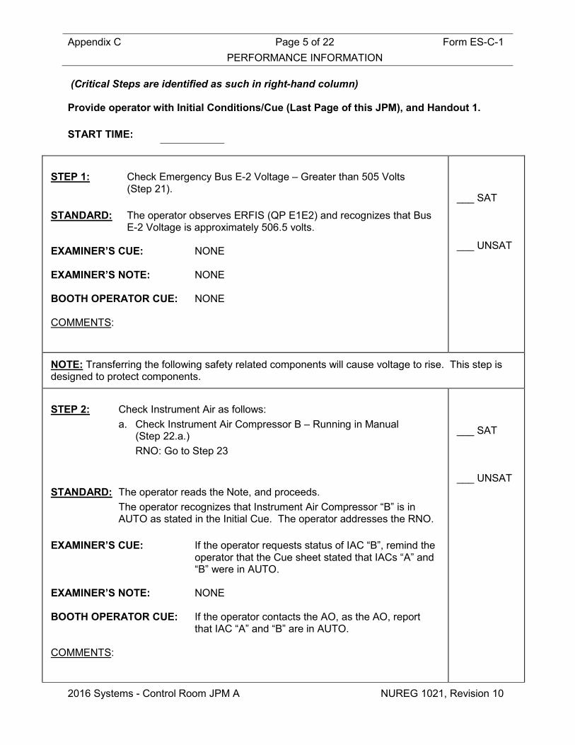
(Critical Steps are identified as such in right-hand column) Provide operator with Initial Conditions/Cue (Last Page of this JPM), and Handout 1. START TIME:
STEP 1: Check Emergency Bus E-2 Voltage – Greater than 505 Volts
(Step 21).
STANDARD: The operator observes ERFIS (QP E1E2) and recognizes that Bus E-2 Voltage is approximately 506.5 volts.
EXAMINER’S CUE: NONE EXAMINER’S NOTE: NONE BOOTH OPERATOR CUE: NONE COMMENTS:
___ SAT ___ UNSAT
NOTE: Transferring the following safety related components will cause voltage to rise. This step is designed to protect components.
STEP 2: Check Instrument Air as follows:
a. Check Instrument Air Compressor B – Running in Manual (Step 22.a.) RNO: Go to Step 23
STANDARD: The operator reads the Note, and proceeds. The operator recognizes that Instrument Air Compressor “B” is in
AUTO as stated in the Initial Cue. The operator addresses the RNO. EXAMINER’S CUE: If the operator requests status of IAC “B”, remind the
operator that the Cue sheet stated that IACs “A” and “B” were in AUTO.
EXAMINER’S NOTE: NONE BOOTH OPERATOR CUE: If the operator contacts the AO, as the AO, report
that IAC “A” and “B” are in AUTO. COMMENTS:
___ SAT ___ UNSAT

Appendix C Page 6 of 22 Form ES-C-1 PERFORMANCE INFORMATION
2016 Systems - Control Room JPM A NUREG 1021, Revision 10
NOTE: For conditions where it may not be possible to reduce emergency bus voltages below 505 volts AND running of the EDG is required to ensure that the EDG is operable, testing of the EDG may be performed with concurrence from the system engineer if the system engineer determines that such testing does not constitute a long term degradation risk. STEP 3: Check EDG “B” Status as Follows:
a. Check Main Generator – ON LINE (Step 23.a.)
STANDARD: The operator reads the Note, and proceeds. The operator observes the 52/8 and 52/9 Red status lights are LIT
and Green status lights are OFF (or equivalent), and concludes that the Main Generator is ON Line.
EXAMINER’S CUE: NONE EXAMINER’S NOTE: NONE BOOTH OPERATOR CUE: NONE COMMENTS:
___ SAT ___ UNSAT
STEP 4: Check EDG “B” Status as Follows:
b. Check EMERGENCY DIESEL GENERATOR B - RUNNING (Step 23.b.)
STANDARD: The operator observes the “B” EDG Green OFF status light is LIT
and concludes that the “B” EDG is NOT running. EXAMINER’S CUE: NONE EXAMINER’S NOTE: NONE BOOTH OPERATOR CUE: NONE COMMENTS:
___ SAT ___ UNSAT

Appendix C Page 7 of 22 Form ES-C-1 PERFORMANCE INFORMATION
2016 Systems - Control Room JPM A NUREG 1021, Revision 10
STEP 5: Check EDG “B” Status as Follows:
b. RNO: Postpone EDG “B” testing while in the AOP. Go to Step 24. Check EMERGENCY DIESEL GENERATOR B - RUNNING (Step 23.b. RNO)
STANDARD: The operator proceeds to Step 24. EXAMINER’S CUE: If the operator informs the CRS to postpone
EMERGENCY DIESEL GENERATOR “B” testing while in this procedure, acknowledge as the CRS.
EXAMINER’S NOTE: NONE BOOTH OPERATOR CUE: If the operator contacts the System Engineer to
postpone EMERGENCY DIESEL GENERATOR “B” testing while in this procedure, acknowledge as the System Engineer.
COMMENTS:
___ SAT ___ UNSAT
STEP 6: Log the Time That Any of the Following Equipment Is OR Was
Running Above 505 Volts. • INSTRUMENT AIR COMPRESSOR B • EDG B PRE-LUBE OIL PUMP • Fuel Oil Transfer Pump B
(Step 24) STANDARD: The operator recognizes that NONE of these components are
running. EXAMINER’S CUE: Inform operator that another operator will track the
run times. EXAMINER’S NOTE: The “B” IAC is in AUTO and the “B” EDG is NOT
RUNNING. BOOTH OPERATOR CUE: NONE COMMENTS:
___ SAT ___ UNSAT

Appendix C Page 8 of 22 Form ES-C-1 PERFORMANCE INFORMATION
2016 Systems - Control Room JPM A NUREG 1021, Revision 10
STEP 7: Check Load On Emergency Bus E-1 – HAS BEEN RAISED USING
STEP 18. (Step 25) Go to Step 27
(Step 25 RNO) STANDARD: The operator recognizes that load on Emergency Bus E-1 has NOT
been raised based on information given in the Initial Cue. EXAMINER’S CUE: NONE EXAMINER’S NOTE: This would have been completed in Step 18 of AOP-
031, which was bypassed. BOOTH OPERATOR CUE: NONE COMMENTS:
___ SAT ___ UNSAT
STEP 8: Raise Load On Emergency BUS E-2 As Follows:
a. Check Charging Pump C - Running (Step 27.a)
STANDARD: The operator observes the “C” Charging Pump Red status light is
LIT and the Green status light is OFF (Or equivalent) and concludes that Charging Pump “C” is running.
EXAMINER’S CUE: NONE EXAMINER’S NOTE: NONE BOOTH OPERATOR CUE: NONE COMMENTS:
___ SAT ___ UNSAT

Appendix C Page 9 of 22 Form ES-C-1 PERFORMANCE INFORMATION
2016 Systems - Control Room JPM A NUREG 1021, Revision 10
STEP 9: Raise Load On Emergency BUS E-2 As Follows:
b. Verify CV RECIRC FANS – RUNNING - HVH-3 - HVH-4
(Step 27.b) STANDARD: The operator observes the HVH-3 Red ON status light is LIT and
concludes that HVH-3 is running. The operator observes the HVH-4 Red ON status light is LIT and
concludes that HVH-4 is running. EXAMINER’S CUE: NONE EXAMINER’S NOTE: NONE BOOTH OPERATOR CUE: NONE COMMENTS:
___ SAT ___ UNSAT
STEP 10: Check CONT RM AIR HANDLING HVA-1B - RUNNING
(Step 27.c) STANDARD: The operator observes the HVA-1B Red ON status light is LIT and
concludes that HVH-1B is running. EXAMINER’S CUE: NONE EXAMINER’S NOTE: NONE BOOTH OPERATOR CUE: NONE COMMENTS:
___ SAT ___ UNSAT
Appendix C Page 10 of 22 Form ES-C-1 PERFORMANCE INFORMATION
2016 Systems - Control Room JPM A NUREG 1021, Revision 10
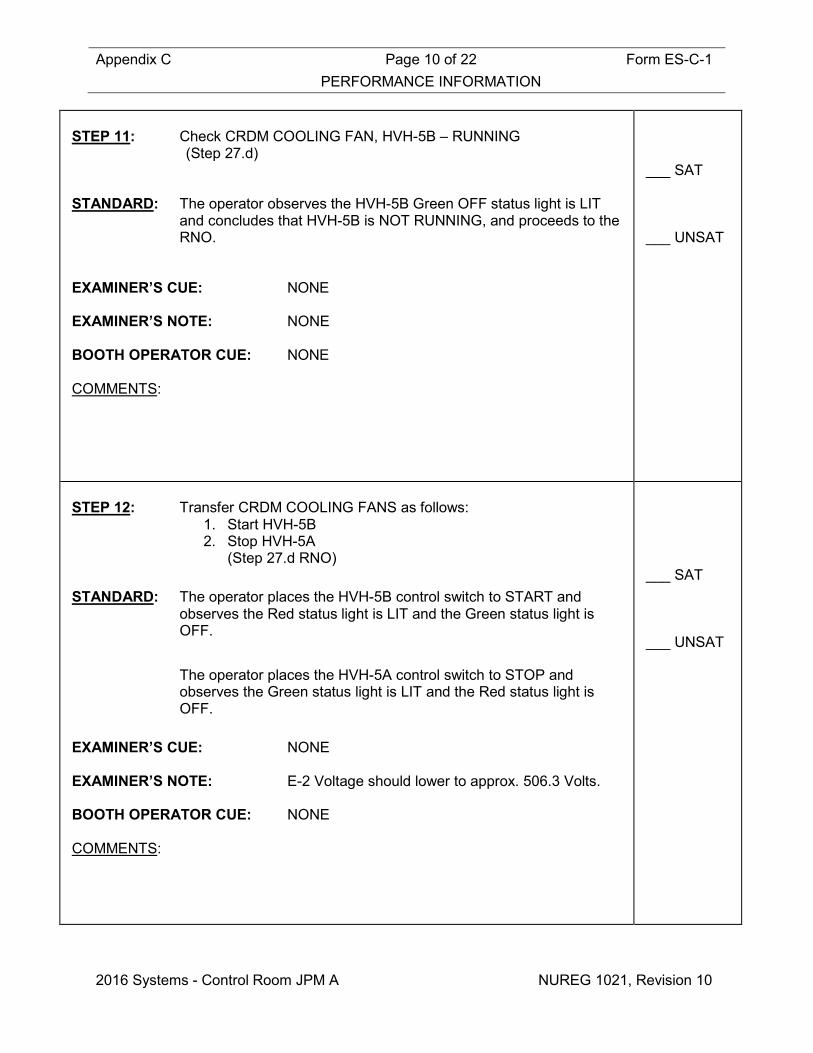
STEP 11: Check CRDM COOLING FAN, HVH-5B – RUNNING (Step 27.d) STANDARD: The operator observes the HVH-5B Green OFF status light is LIT
and concludes that HVH-5B is NOT RUNNING, and proceeds to the RNO.
EXAMINER’S CUE: NONE EXAMINER’S NOTE: NONE BOOTH OPERATOR CUE: NONE COMMENTS:
___ SAT ___ UNSAT
STEP 12: Transfer CRDM COOLING FANS as follows:
1. Start HVH-5B 2. Stop HVH-5A
(Step 27.d RNO) STANDARD: The operator places the HVH-5B control switch to START and
observes the Red status light is LIT and the Green status light is OFF.
The operator places the HVH-5A control switch to STOP and
observes the Green status light is LIT and the Red status light is OFF.
EXAMINER’S CUE: NONE EXAMINER’S NOTE: E-2 Voltage should lower to approx. 506.3 Volts. BOOTH OPERATOR CUE: NONE COMMENTS:
___ SAT ___ UNSAT

Appendix C Page 11 of 22 Form ES-C-1 PERFORMANCE INFORMATION
2016 Systems - Control Room JPM A NUREG 1021, Revision 10
STEP 13: Check AUX BLDG EXH FAN, HVE-2B - RUNNING
(Step 27.e) STANDARD: The operator observes the HVE-2B Green OFF status light is LIT
and concludes that HVE-2B is NOT running, and proceeds to the RNO.
EXAMINER’S CUE: NONE EXAMINER’S NOTE: NONE BOOTH OPERATOR CUE: NONE COMMENTS:
___ SAT ___ UNSAT
STEP 14: Transfer AUX BLDG EXH FANs as follows:
1) Start HVE-2B 2) Stop HVE-2A
(Step 27.e RNO) STANDARD: The operator places the HVE-2B control switch to START and
observes the Red status light is LIT and the Green status light is OFF.
The operator places the HVE-2A control switch to STOP and
observes the Green status light is LIT and the Red status light is OFF.
EXAMINER’S CUE: NONE EXAMINER’S NOTE: E-2 Voltage should lower to approx. 506.2 Volts. BOOTH OPERATOR CUE: NONE COMMENTS:
___ SAT ___ UNSAT

Appendix C Page 12 of 22 Form ES-C-1 PERFORMANCE INFORMATION
2016 Systems - Control Room JPM A NUREG 1021, Revision 10
STEP 15: Check RHR – IN SERVICE.
(Step 27. f) STANDARD: The operator recognizes that the plant is in Mode 1 and determines
that RHR is NOT is IN SERVICE. The operator addresses the RNO and proceeds to Step 28.
EXAMINER’S CUE: NONE EXAMINER’S NOTE: NONE BOOTH OPERATOR CUE: NONE COMMENTS:
___ SAT ___ UNSAT
STEP 16: Check Emergency BUS E-2 Voltage – GREATER THAN 505
VOLTS (Step 28)
STANDARD: The operator observes Bus E-2 Voltage on ERFIS to be greater than 505 Volts (506.2 volts).
EXAMINER’S CUE: NONE EXAMINER’S NOTE: NONE BOOTH OPERATOR CUE: NONE COMMENTS:
___ SAT ___ UNSAT

Appendix C Page 13 of 22 Form ES-C-1 PERFORMANCE INFORMATION
2016 Systems - Control Room JPM A NUREG 1021, Revision 10
STEP 17: Check DSDG Status As Follows:
a. Check Main Generator – ON LINE (Step 29.a)
STANDARD: The operator observes the 52/8 and 52/9 Red status lights are LIT
and Green status lights are OFF (or equivalent), and concludes that the Main Generator is ON Line.
EXAMINER’S CUE: NONE EXAMINER’S NOTE: NONE BOOTH OPERATOR CUE: NONE COMMENTS:
___ SAT ___ UNSAT
STEP 18: Check DSDG Status As Follows:
b. Check DSDG - RUNNING (Step 29.b)
STANDARD: The operator recognizes that DSDG is secured and aligned for
AUTO as stated in the Initial Cue. The operator addresses the RNO.
EXAMINER’S CUE: If the operator requests status of the DSDG, remind
the operator that the Cue sheet stated that the DSDG was secured and aligned for AUTO.
EXAMINER’S NOTE: NONE BOOTH OPERATOR CUE: If the operator contacts the AO, as the AO, report
that the DSDG is secured and aligned for AUTO. COMMENTS:
___ SAT ___ UNSAT

Appendix C Page 14 of 22 Form ES-C-1 PERFORMANCE INFORMATION
2016 Systems - Control Room JPM A NUREG 1021, Revision 10
STEP 19: Check DSDG Status As Follows:
b. RNO: Postpone DSDG testing while in this AOP. Go to Step 30. (Step 29.b RNO)
STANDARD: The operator proceeds to step 30. EXAMINER’S CUE: If operator informs the CRS to postpone DSDG
testing while in this procedure, acknowledge as the CRS.
EXAMINER’S NOTE: NONE BOOTH OPERATOR CUE: If the operator contacts the System Engineer to
postpone DSDG testing while in this procedure, acknowledge as the System Engineer.
COMMENTS:
___ SAT ___ UNSAT
STEP 20: Check 4KV BUS 3-4 TIE, BKR 52-19 - OPEN
(Step 30) STANDARD: The operator observes 4KV BUS 3-4 TIE, BKR 52-19 Green status
light is LIT and Red status light is OFF, and determines that BKR 52-19 IS OPEN.
EXAMINER’S CUE: NONE EXAMINER’S NOTE: BKR 52-19 indicates OPEN (TRIP) by GREEN light
lit. BOOTH OPERATOR CUE: NONE COMMENTS:
___ SAT ___ UNSAT

Appendix C Page 15 of 22 Form ES-C-1 PERFORMANCE INFORMATION
2016 Systems - Control Room JPM A NUREG 1021, Revision 10
STEP 21: Transfer 4160V BUS 4 to the STARTUP TRANSFORMER as
follows: a. Insert the Synchroscope Key into 4 KV TIES Synchroscope Key
Switch (Step 31.a)
STANDARD: The operator inserts the synchroscope key into 4 KV TIES
Synchroscope Key Switch. EXAMINER’S CUE: NONE EXAMINER’S NOTE: NONE BOOTH OPERATOR CUE: NONE COMMENTS:
CRITICAL
STEP ___ SAT ___ UNSAT
STEP 22: Transfer 4160V BUS 4 to the STARTUP TRANSFORMER as
follows: b. Place the Synchroscope Switch to the BUS 3 & 4 position (Step 31.b)
STANDARD: The operator rotates the Synchroscope Switch clockwise to the
BUS 3 & 4 position. EXAMINER’S CUE: NONE EXAMINER’S NOTE: NONE BOOTH OPERATOR CUE: NONE COMMENTS:
CRITICAL
STEP ___ SAT ___ UNSAT

Appendix C Page 16 of 22 Form ES-C-1 PERFORMANCE INFORMATION
2016 Systems - Control Room JPM A NUREG 1021, Revision 10
STEP 23: Transfer 4160V BUS 4 to the STARTUP TRANSFORMER as
follows: c. Verify the Synchroscope comes to approximately the 12 o’clock
position. (Step 31.c)
STANDARD: The operator observes that the Synchroscope is pointing to the 12
o’clock position. EXAMINER’S CUE: NONE EXAMINER’S NOTE: NONE BOOTH OPERATOR CUE: NONE COMMENTS:
___ SAT ___ UNSAT
STEP 24: Transfer 4160V BUS 4 to the STARTUP TRANSFORMER as
follows: d. Momentarily place the Control Switch for 4KV BUS 3-4 TIE,
BKR 52/19 to the CLOSE position. (Step 31.d)
STANDARD: The operator momentarily places the control switch for BKR 52/19
to the CLOSE position. EXAMINER’S CUE: NONE EXAMINER’S NOTE: NONE BOOTH OPERATOR CUE: NONE COMMENTS:
CRITICAL
STEP ___ SAT ___ UNSAT
Appendix C Page 17 of 22 Form ES-C-1 PERFORMANCE INFORMATION
2016 Systems - Control Room JPM A NUREG 1021, Revision 10
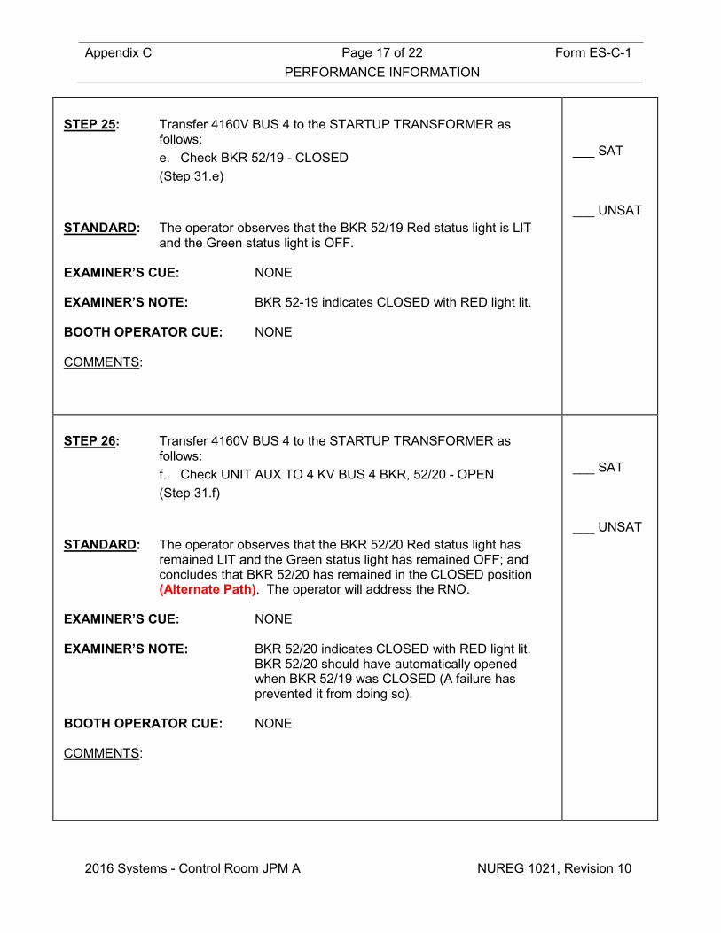
STEP 25: Transfer 4160V BUS 4 to the STARTUP TRANSFORMER as
follows: e. Check BKR 52/19 - CLOSED (Step 31.e)
STANDARD: The operator observes that the BKR 52/19 Red status light is LIT
and the Green status light is OFF. EXAMINER’S CUE: NONE EXAMINER’S NOTE: BKR 52-19 indicates CLOSED with RED light lit. BOOTH OPERATOR CUE: NONE COMMENTS:
___ SAT ___ UNSAT
STEP 26: Transfer 4160V BUS 4 to the STARTUP TRANSFORMER as
follows: f. Check UNIT AUX TO 4 KV BUS 4 BKR, 52/20 - OPEN (Step 31.f)
STANDARD: The operator observes that the BKR 52/20 Red status light has
remained LIT and the Green status light has remained OFF; and concludes that BKR 52/20 has remained in the CLOSED position (Alternate Path). The operator will address the RNO.
EXAMINER’S CUE: NONE EXAMINER’S NOTE: BKR 52/20 indicates CLOSED with RED light lit.
BKR 52/20 should have automatically opened when BKR 52/19 was CLOSED (A failure has prevented it from doing so).
BOOTH OPERATOR CUE: NONE COMMENTS:
___ SAT ___ UNSAT

Appendix C Page 18 of 22 Form ES-C-1 PERFORMANCE INFORMATION
2016 Systems - Control Room JPM A NUREG 1021, Revision 10
STEP 27: Transfer 4160V BUS 4 to the STARTUP TRANSFORMER as
follows: f. RNO: Perform the following
• Simultaneously depress the THINK pushbutton AND place the control switch for BKR 52/20 to the OPEN position.
(Step 31.f RNO) STANDARD: The operator simultaneously depresses the THINK pushbutton and
places the control switch for BKR 52/20 to the OPEN (TRIP) position, and observes that the Green status light is LIT and the Red status light is OFF.
EXAMINER’S CUE: NONE EXAMINER’S NOTE: BKR 52/20 indicates OPEN (TRIP) with GREEN
light lit. When this occurs Bus E-2 voltage will drop to 484.8 volts.
BOOTH OPERATOR CUE: NONE COMMENTS:
CRITICAL
STEP ___ SAT ___ UNSAT
Appendix C Page 19 of 22 Form ES-C-1 PERFORMANCE INFORMATION
2016 Systems - Control Room JPM A NUREG 1021, Revision 10
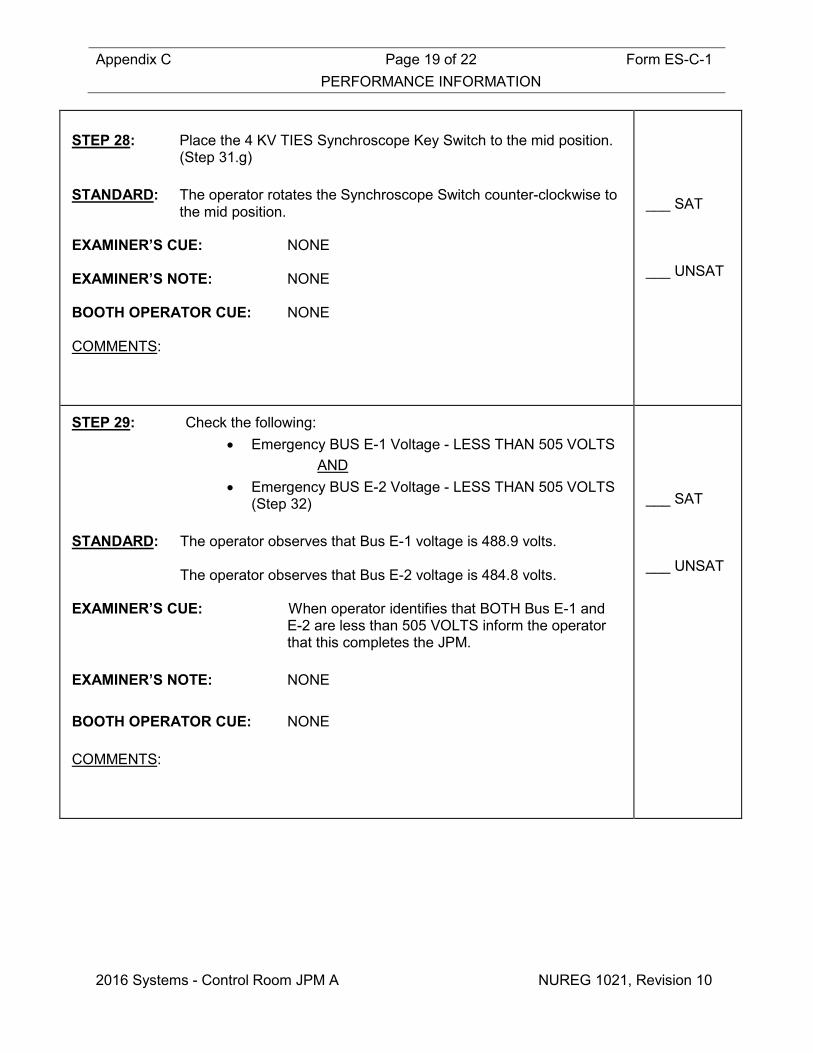
STEP 28: Place the 4 KV TIES Synchroscope Key Switch to the mid position.
(Step 31.g) STANDARD: The operator rotates the Synchroscope Switch counter-clockwise to
the mid position. EXAMINER’S CUE: NONE EXAMINER’S NOTE: NONE BOOTH OPERATOR CUE: NONE COMMENTS:
___ SAT ___ UNSAT
STEP 29: Check the following: • Emergency BUS E-1 Voltage - LESS THAN 505 VOLTS
AND • Emergency BUS E-2 Voltage - LESS THAN 505 VOLTS
(Step 32) STANDARD: The operator observes that Bus E-1 voltage is 488.9 volts. The operator observes that Bus E-2 voltage is 484.8 volts. EXAMINER’S CUE: When operator identifies that BOTH Bus E-1 and
E-2 are less than 505 VOLTS inform the operator that this completes the JPM.
EXAMINER’S NOTE: NONE BOOTH OPERATOR CUE: NONE COMMENTS:
___ SAT ___ UNSAT

Appendix C Page 20 of 22 Form ES-C-1 PERFORMANCE INFORMATION
2016 Systems - Control Room JPM A NUREG 1021, Revision 10
STEP 30: Check Voltage as Follows: (Continuous Action Step) • APP-036-E3, SUT PRI OVER/UNDER VOLTAGE –
EXTINGUISHED AND
• WEST 115KV BUS VOLTAGE – LESS THAN 119 KV AND
• Emergency BUS E-1 Voltage – LESS THAN 502 VOLTS AND
• Emergency BUS E-2 Voltage – LESS THAN 502 VOLTS (Step 33)
STANDARD: The operator observes that APP-036-E3 is DARK. The operator observes that WEST 115KV BUS VOLTAGE is 18.8
KV. The operator observes that Bus E-1 voltage is 488.9 volts. The operator observes that Bus E-2 voltage is 484.8 volts. EXAMINER’S CUE: When operator identifies that BOTH Bus E-1 and
E-2 are less than 502 VOLTS inform the operator that this completes the JPM.
EXAMINER’S NOTE: NONE BOOTH OPERATOR CUE: NONE COMMENTS:
___ SAT ___ UNSAT
Terminating Cue: Evaluation on this JPM is complete. STOP TIME:

Appendix C Page 21 of 22 Form ES-C-1 VERIFICATION OF COMPLETION
2016 Systems - Control Room JPM A NUREG 1021, Revision 10
Job Performance Measure No.: 2016 Systems - Control Room JPM A
Examinee’s Name:
Date Performed:
Facility Evaluator:
Number of Attempts:
Time to Complete:
Question Documentation:
Result: SAT UNSAT Examiner’s Signature: Date:
Appendix C Form ES-C-1 JPM CUE SHEET
NUREG 1021, Revision 10
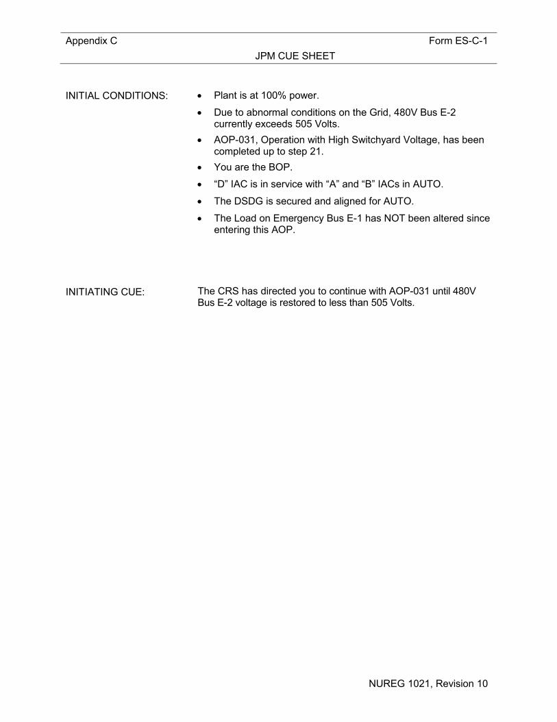
INITIAL CONDITIONS: • Plant is at 100% power.
• Due to abnormal conditions on the Grid, 480V Bus E-2 currently exceeds 505 Volts.
• AOP-031, Operation with High Switchyard Voltage, has been completed up to step 21.
• You are the BOP.
• “D” IAC is in service with “A” and “B” IACs in AUTO.
• The DSDG is secured and aligned for AUTO.
• The Load on Emergency Bus E-1 has NOT been altered since entering this AOP.
INITIATING CUE: The CRS has directed you to continue with AOP-031 until 480V
Bus E-2 voltage is restored to less than 505 Volts.

Appendix C Job Performance Measure Form ES-C-1 Worksheet
2016 Systems - Control Room JPM B (Rev_011216) NUREG 1021, Revision 10
SIM JPM B Developed By: ______________________________ Date: ___________ Instructor/Developer Concurred By: ______________________________ Date: ___________ Line Superintendent/Supervisor SRO Approved By: ______________________________ Date: ___________ Superintendent/Supervisor Training

Appendix C Page 2 of 13 Form ES-C-1 Job Performance Measure Worksheet
2016 Systems - Control Room JPM B NUREG 1021, Revision 10
Facility: HB Robinson Task No.: Task Title: Transfer From the FRV Bypass
Valves to the FRVs JPM No.: 2016 Systems - Control
Room JPM B (Alternate Path)
K/A Reference: 059 A4.08 (3.2/2.9) Examinee: NRC Examiner:
Facility Evaluator: Date:
Method of testing:
Simulated Performance: Actual Performance: X Classroom Simulator X Plant
READ TO THE EXAMINEE
I will explain the initial conditions, which steps to simulate or discuss, and provide initiating cues. When you complete the task successfully, the objective for this Job Performance Measure will be satisfied.
Provide operator with Initial Conditions/Cue (Last Page of this JPM), and Handout 1. Initial Conditions: • A plant startup is in progress with reactor power approximately 19%. • “A” and “B” S/G levels are being controlled with the Feed Reg Valves
operating in AUTO. • The “C” S/G level is being controlled manually on both the Feed Reg
Valve and the Feed Reg Bypass Valve. • The Turbine is at 1800 RPM (Not synched to the Grid). • You are the operator assigned to control S/G water level. • Annunciator APP-003-D4, TAVE/TREF DEV, is an expected alarm. Initiating Cue: The CRS has directed you to transfer the “C” S/G level control to the Main
Feedwater Regulating Valve in accordance with Step 6.4.12 of GP-005, Power Operation.
Task Standard: The operator will place the “C” Feed Reg Valve in AUTO, and then take
manual control of the “B” Feed Reg Valve and stabilize the “B” S/G level when it is determined that the “B” Feed Reg Valve has failed to control the “B” S/G level in AUTO.

Appendix C Page 3 of 13 Form ES-C-1 Job Performance Measure Worksheet
2016 Systems - Control Room JPM B NUREG 1021, Revision 10
Required Materials: None General References: GP-005 (Power Operation), Rev 128 AOP-010 (Main Feedwater/Condensate Malfunction), Rev 33 Handouts: Handout 1: Section 6.4 of GP-005 marked up for this JPM through Step
6.12.d for “A” and “B” FRVs. Handout 2: Blank copy of AOP-010 Time Critical Task: NO Validation Time: 12 minutes NOTE: This JPM should be pre-briefed in the Briefing Room.
Critical Step Justification
Step 2 This step is critical because adjusting the output of the FCV-499 controller is
necessary to place the “C” Feed Reg Valve in AUTO. Step 3 This step is critical because depressing the AUTO pushbutton on the FCV-498
controller is necessary to place the “C” Feed Reg Valve in AUTO. Step 4 This step is critical because rotating the FCV-499 controller adjust knob counter-
clockwise until the controller is at 0% is necessary to place the “C” Feed Reg Valve in AUTO.
Alternate Path Critical Step Justification
Step 5 or 7 This step is critical because placing the FCV-488 controller in MANUAL and
stabilizing the “B” S/G level is necessary to take manual control of the “B” Feed Reg Valve and stabilize the “B” S/G level.

Appendix C Page 4 of 13 Form ES-C-1 Job Performance Measure Worksheet
2016 Systems - Control Room JPM B NUREG 1021, Revision 10
SIMULATOR OPERATIONAL GUIDELINES 1. Reset simulator to IC-3, ≈16% Power, Turbine Ready for Synch 2. Place in RUN.
3. Perform the following:
• Raise power to 18-20% by withdrawing control rods. • Adjust FRV Bypasses to 60-90% OPEN. • Override CLOSED FCV-1446 (1CFW094 f:normal)
4. Ensure the following:
• Rx power is between 17-20% • Tavg is between 551-555°F • The “C” FRV Bypass Valve OPEN with 60-90% output demand • The “C” S/G level is within 2-4% of programmed level (39%) • The “A” and “B” FRV Controllers are in AUTO • The “C” FRV Controller is in MANUAL • FCV-1446 indicates SHUT
5. Insert $006_FRV_BYPASS IMF CFW17B d:5 r:90 f:0 (5 seconds after FCV-499 (“C” Feed
Reg Bypass Valve) OPEN indication extinguishes) 6. Identify APP-003-D4, TAVE/TREF DEV, and an expected alarm (Green Dot)
7. Place Green Dots on all other LIT annunciators (Expected alarms) 8. Acknowledge alarms and stabilize plant. 9. Freeze the Simulator. OR 1. Reset Simulator to Temporary Snap IC-601 (January, 2016). 2. Open Scenario File 006_JPM_B.
3. Perform Attachment 2 (Simulator Setup For Exams) of TAP-411. 4. Place Simulator in Run when Operator assumes the watch.

Appendix C Page 5 of 13 Form ES-C-1 PERFORMANCE INFORMATION
2016 Systems - Control Room JPM B NUREG 1021, Revision 10
(Critical Steps are identified as such in right-hand column) Provide operator with Initial Conditions/Cue (Last Page of this JPM), and Handout 1. START TIME:
NOTE
Section 6.4 Step 12 is a continuous action step that should be performed whenever plant conditions require Feedwater flow through the FRVs and conditions are suitable or automatic S/G water level control. Feedwater Regulating Valves should be transferred to automatic control one at a time. FCV-1446 (Condensate Recirc) is controlled by FS-1446 (Cond Pmp Recirc VLV Flow Switch). FS-1446 is set to open FCV-1446 at a flow of 1050 gpm with the valve closing at a Condensate System flow of 4200 gpm flow through the GS Condenser and SGBD Heat Exchangers. The Push Button to reset FS-1446 is located in the same enclosure as FS-1446 which is located approximately 15 feet northwest of FCV-1446 on a concrete column. STEP 1: WHEN Reactor Power is 15% to 20%, OR the Feedwater
Regulating Bypass Valves are 60% to 90% demand signal, THEN shift each Feedwater Regulating Valve to AUTO as follows: • IF FCV-1446 (Condenser Recirc) does NOT indicate SHUT,
THEN……. (Step 12/12.a).
STANDARD: The operator reads the Notes, and proceeds. The operator observes reactor power on NR-45 (or equivalent) to be
18%, and proceeds. The operator observes that FCV-499 Controller output to be
between 60-90%, and proceeds. The operator observes the FCV-1446 Green status light is LIT and
Red status light is OFF, and recognizes that this Step is NOT Applicable, and proceeds.
EXAMINER’S CUE: NONE EXAMINER’S NOTE: NONE BOOTH OPERATOR CUE: NONE COMMENTS:
___ SAT ___ UNSAT

Appendix C Page 6 of 13 Form ES-C-1 PERFORMANCE INFORMATION
2016 Systems - Control Room JPM B NUREG 1021, Revision 10
NOTE
With the Turbine not yet loaded, S/G Program Level will be approximately 39% based on First Stage Pressure. STEP 2: Ensure Feed Flow is trending with Steam Flow and S/G Levels are
within 1% of program level. (Step 12.b).
STANDARD: The operator reads the Note, and proceeds. The operator observes “C” S/G Feed Flow is trending with Steam
Flow, and that “C” S/G level is NOT within 1% of programmed level. The operator adjusts the output of the FCV-499 controller as needed
to adjust the feed flow trend and/or “C” S/G level within 1% of programmed level.
EXAMINER’S CUE: APP-003-D4, which is an expected alarm, may alarm
during this time. If so, state that the OATC will address this alarm.
It may be necessary to provide this cue throughout the
JPM. EXAMINER’S NOTE: S/G programmed level is 39%. BOOTH OPERATOR CUE: NONE COMMENTS:
CRITICAL
STEP ___ SAT ___ UNSAT

Appendix C Page 7 of 13 Form ES-C-1 PERFORMANCE INFORMATION
2016 Systems - Control Room JPM B NUREG 1021, Revision 10
STEP 3: Depress the Auto pushbutton on the FRV controller.
(Step 12.c) STANDARD: The operator observes that “C” S/G level is within 1% of
programmed level. The operator depresses the AUTO pushbutton on the FCV-498
controller, and observes the White AUTO light is LIT. EXAMINER’S CUE: NONE EXAMINER’S NOTE: NONE BOOTH OPERATOR CUE: NONE COMMENTS:
CRITICAL
STEP ___ SAT ___ UNSAT

Appendix C Page 8 of 13 Form ES-C-1 PERFORMANCE INFORMATION
2016 Systems - Control Room JPM B NUREG 1021, Revision 10
STEP 4: IF ANY Feedwater Regulating Bypass Valve is NOT closed, THEN
slowly close it (Step 12.c.1)
STANDARD: The operator observes FCV-499 to be OPEN, and rotates the
controller adjust knob counter-clockwise, and observes the controller output move toward 0%.
The operator observes the FCV-498 Red and Green status light is
LIT, and the controller output start to rise from 0%. EXAMINER’S CUE: S/G level may drop as much as 5% while the FRV
adjusts automatically, and this may result in an APP-006 deviation alarm (This is normal and expected). However, the operator may take action per AOP-010, and place the FRV controller in MANUAL.
If so, when the “C” S/G level is under the operator’s
control, report as I&C that troubleshooting has been conducted (Using time compression), and it has been determined that the FCV-498 controller is operating properly.
EXAMINER’S NOTE: NONE BOOTH OPERATOR CUE: NONE COMMENTS:
CRITICAL STEP
___ SAT ___ UNSAT

Appendix C Page 9 of 13 Form ES-C-1 PERFORMANCE INFORMATION
2016 Systems - Control Room JPM B NUREG 1021, Revision 10
STEP 5: Ensure each FRV in AUTO is maintaining programmed S/G level. (Step 12.d)
STANDARD: The operator observes that “C” S/G level is stabilized and concludes
that the “C” FRV (FCV-498) is maintaining programmed S/G level in AUTO.
The operator observes one or more of the following:
• “B” Feed flow as indicated on FR-488 starts to lower • “B” S/G level as indicated on FR-488 starts to lower • FCV-488 controller output starts to lower • FCV-488 Green status light is LIT, Red status light is OFF • APP-006-E1, S/G B NAR RANGE LO/LO-LO LEVEL
(Alternate Path) The operator depresses the MANUAL pushbutton on the FCV-488
controller, and observes the White AUTO light is Extinguished; and the “B” S/G is stabilized (i.e. under the operator control). (If so, Terminate JPM)
OR The operator addresses AOP-010. (If so, continue to subsequent
Steps) EXAMINER’S CUE: If the operator addresses AOP-010, provide the
operator with a copy of Handout 2, and continue. EXAMINER’S NOTE: 5 seconds after the “C” FRBV is closed the “B” FRV
controller will fail causing FCV-488 to CLOSE. The operator is expected to take manual control of
FCV-488 using the guidance for Prompt and Prudent actions in OMM-022, Step 5.3.1.c. (Prompt action is necessary to prevent the deterioration of plant conditions or components to a possibly unsafe or unstable level. If time permits, approval from the SM/CRS shall be obtained. Factors to consider include: complexity of action, potential for damage from common cause, etc. Examples include: Failure of automatic systems to perform or respond correctly.); or by entering AOP-010. If the operator addresses AOP-010, continue.
BOOTH OPERATOR CUE: NONE COMMENTS:
CRITICAL STEP
___ SAT ___ UNSAT

Appendix C Page 10 of 13 Form ES-C-1 PERFORMANCE INFORMATION
2016 Systems - Control Room JPM B NUREG 1021, Revision 10
STEP 6: CHECK FRVs ‑ OPERATING PROPERLY (MANUAL OR AUTO): FCV‑478
FCV‑488 FCV‑498 (AOP-010 Step 1)
STANDARD: The operator observes one or more of the following:
• “B” Feed flow as indicated on FR-488 starts to lower • “B” S/G level as indicated on FR-488 starts to lower • FCV-488 controller output starts to lower • FCV-488 Green status light is LIT, Red status light is OFF • APP-006-E1, S/G B NAR RANGE LO/LO-LO LEVEL
The operator proceeds to Step 1 RNO. EXAMINER’S CUE: NONE EXAMINER’S NOTE: NONE BOOTH OPERATOR CUE: NONE COMMENTS:
___ SAT ___ UNSAT
STEP 7: PERFORM the following: ENSURE FRV for affected S/G(s) in manual control. ATTEMPT to stabilize S/G level using FRV and/or FRV Bypass Valves by matching steam flow with feed flow. STOP any load change in progress. If unable to control S/G level, THEN TRIP the reactor and GO TO EOP‑E‑0, Reactor Trip Or Safety Injection. (AOP-010 Step 1 RNO)
STANDARD: The operator places FCV-498 controller in MANUAL and stabilizes
the “B” S/G level. EXAMINER’S CUE: NONE EXAMINER’S NOTE: NONE BOOTH OPERATOR CUE: NONE COMMENTS:
CRITICAL STEP
___ SAT ___ UNSAT

Appendix C Page 11 of 13 Form ES-C-1 PERFORMANCE INFORMATION
2016 Systems - Control Room JPM B NUREG 1021, Revision 10
STEP 8: CHECK Reactor Trip Setpoint ‑ BEING APPROACHED (AOP-010 Step 2)
STANDARD: The operator observes that the “B” S/G level is stabilized. EXAMINER’S CUE: NONE EXAMINER’S NOTE: NONE BOOTH OPERATOR CUE: NONE COMMENTS:
___ SAT ___ UNSAT
STEP 9: IF a reactor trip setpoint is approached, THEN TRIP the reactor and GO TO EOP‑E‑0, Reactor Trip Or Safety Injection.
GO TO Step 4. (AOP-010 Step 2 RNO)
STANDARD: The operator observes that the “B” S/G level is stabilized. EXAMINER’S CUE: NONE EXAMINER’S NOTE: NONE BOOTH OPERATOR CUE: NONE COMMENTS:
___ SAT ___ UNSAT
Terminating Cue: Evaluation on this JPM is complete. STOP TIME:

Appendix C Page 12 of 13 Form ES-C-1 VERIFICATION OF COMPLETION
2016 Systems - Control Room JPM B NUREG 1021, Revision 10
Job Performance Measure No.: 2016 Systems - Control Room JPM B
Examinee’s Name:
Date Performed:
Facility Evaluator:
Number of Attempts:
Time to Complete:
Question Documentation:
Result: SAT UNSAT Examiner’s Signature: Date:

Appendix C Form ES-C-1 JPM CUE SHEET
NUREG 1021, Revision 10
INITIAL CONDITIONS: • A plant startup is in progress with reactor power approximately
19%. • “A” and “B” S/G levels are being controlled with the Feed Reg
Valves operating in AUTO. • The “C” S/G level is being controlled manually on both the
Feed Reg Valve and the Feed Reg Bypass Valve. • The Turbine is at 1800 RPM (Not synched to the Grid).
• You are the operator assigned to control S/G water level.
• Annunciator APP-003-D4, TAVE/TREF DEV, is an expected alarm.
INITIATING CUE: The CRS has directed you to transfer the “C” S/G level control to
the Main Feedwater Regulating Valve in accordance with Step 6.4.12 of GP-005, Power Operation.

Appendix C Job Performance Measure Form ES-C-1 Worksheet
2016 Systems - Control Room JPM C (Rev_011116) NUREG 1021, Revision 10
SIM JPM C Developed By: ______________________________ Date: ___________ Instructor/Developer Concurred By: ______________________________ Date: ___________ Line Superintendent/Supervisor SRO Approved By: ______________________________ Date: ___________ Superintendent/Supervisor Training

Appendix C Page 2 of 17 Form ES-C-1 Job Performance Measure Worksheet
2016 Systems - Control Room JPM C NUREG 1021, Revision 10
Facility: HB Robinson Task No.: Task Title: Restore PRT to Normal Operating
Conditions JPM No.: 2016 Systems - Control
Room JPM C (Alternate Path)
K/A Reference: 007 A1.01 (2.9/3.1) Examinee: NRC Examiner:
Facility Evaluator: Date:
Method of testing:
Simulated Performance: Actual Performance: X Classroom Simulator X Plant
READ TO THE EXAMINEE
I will explain the initial conditions, which steps to simulate or discuss, and provide initiating cues. When you complete the task successfully, the objective for this Job Performance Measure will be satisfied.
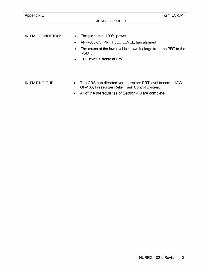
Provide Operator with Initial Conditions/Cue (Last Page of this JPM) and Handout 1. Initial Conditions: • The plant is at 100% power. • APP-003-D3, PRT HI/LO LEVEL, has alarmed. • The cause of the low level is known leakage from the PRT to the
RCDT. • PRT level is stable at 67%. Initiating Cue: • The CRS has directed you to restore PRT level to normal IAW OP-
103, Pressurizer Relief Tank Control System. • All of the prerequisites of Section 4.0 are complete. Task Standard: The operator will refill the PRT in accordance with Section 8.2.2 of OP-
103; and then diagnose and relieve the hydraulic lock on RC-519B in accordance with Section 8.4.1 of OP-103.
Required Materials: None General References: OP-103 (Pressurizer Relief Tank Control System), Rev 21

Appendix C Page 3 of 17 Form ES-C-1 Job Performance Measure Worksheet
2016 Systems - Control Room JPM C NUREG 1021, Revision 10
Handouts: Handout 1: Blank Copy of OP-103 Time Critical Task: NO Validation Time: 10 minutes NOTE: This JPM should be pre-briefed in the briefing room.
Critical Step Justification
Step 2 This step is critical because placing a PW Pump control switch to START is
necessary to refill the PRT in accordance with Section 8.2.2 of OP-103. Step 3 This step is critical because placing the RC-519C control switch to OPEN is
necessary to refill the PRT in accordance with Section 8.2.2 of OP-103. Step 4 This step is critical because placing the RC-519A and B control switch to OPEN is
necessary to refill the PRT in accordance with Section 8.2.2 of OP-103. Step 9 This step is critical because placing the RC-519A and B control switch to CLOSE is
necessary to refill the PRT in accordance with Section 8.2.2 of OP-103. Step 10 This step is critical because placing the RC-519C control switch to CLOSE is
necessary to refill the PRT in accordance with Section 8.2.2 of OP-103.
Alternate Path Critical Step Justification
Step 15 This step is critical because cycling RC-519C open and closed is necessary to relieve the hydraulic lock on RC-519B in accordance with Section 8.4.1 of OP-103.

Appendix C Page 4 of 17 Form ES-C-1 Job Performance Measure Worksheet
2016 Systems - Control Room JPM C NUREG 1021, Revision 10
SIMULATOR OPERATIONAL GUIDELINES 1. Construct Scenario File 006_JPM_ C as follows:
• IOR doRCSAAO212d e:006_RC_519AB_OPEN f:ON (Over-Ride RC-519B to OPEN when Switch taken to OPEN)
• IOR do CNMAOO086J e:006_519AB_OPEN f:OFF (Over-Ride RC-519A/B CIV Indication to OFF)
To be inserted after RC-519C is CLOSED during Initial Fill of PRT (JPM Step 12)
• $006_RC_519C_OPEN DOR doRCSAAO212D (Removes Over-Ride for RC-519B when RC-519C is OPEN)
• $600_RC_519C_OPEN DOR doCNMAOO086J (Removes Over-Ride on RC-519A/B CIV Indication)
2. Reset simulator to IC-5, 100% Power. 3. Place in RUN, execute Scenario File 006_JPM_C and allow time to stabilize. 4. Drain PRT to ≈67% (Open RC-523 until PRT level 67% and Close RC-523. 5. Verify PRT conditions as follows: 103°F temperature, 67% level and 3 psig pressure. 6. Stabilize the plant. 7. Freeze the Simulator. OR 1. Reset Simulator to Temporary Snap IC-602 (July, 2015). 2. Scenario File 006_JPM_ C
NOTE: Booth Instructor verify that two additional overrides are available to be
inserted at Step 11 of this JPM.
3. Perform Attachment 2 (Simulator Setup For Exams) of TAP-411. 4. Place Simulator in Run when Operator assumes the watch.

Appendix C Page 5 of 17 Form ES-C-1 PERFORMANCE INFORMATION
2016 Systems - Control Room JPM C NUREG 1021, Revision 10
(Critical Steps are identified as such in right-hand column) Provide Operator with Initial Conditions/Cue (Last Page of this JPM) and Handout 1. START TIME:
NOTE:
PRT temperatures of greater than 120°F should be reduced by alternately adding Primary Water to the PRT and draining the PRT. (SER 93-007)
Maximum cooling effect can be achieved by leaving the added Primary Water in the PRT for at least 10 minutes prior to draining. (SER 93-007)
STEP 1: Verify the following initial conditions are satisfied:
a. All prerequisites of Section 4.0 are complete b. Pressurizer Relief Tank level is less than 80%. c. Draining the PRT is NOT in progress.
(Step 8.2.2.1) STANDARD: The operator reads the Notes, and proceeds. The operator Verifies all initial conditions satisfied (Initial Cue). EXAMINER’S CUE: If asked, section 4.0 prerequisites are complete. EXAMINER’S NOTE: NONE BOOTH OPERATOR CUE: NONE COMMENTS:
___ SAT ___ UNSAT
Appendix C Page 6 of 17 Form ES-C-1 PERFORMANCE INFORMATION
2016 Systems - Control Room JPM C NUREG 1021, Revision 10
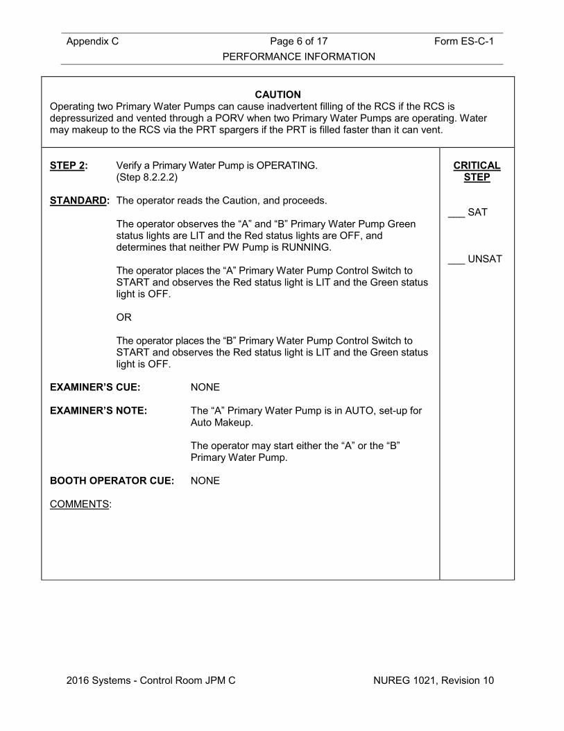
CAUTION
Operating two Primary Water Pumps can cause inadvertent filling of the RCS if the RCS is depressurized and vented through a PORV when two Primary Water Pumps are operating. Water may makeup to the RCS via the PRT spargers if the PRT is filled faster than it can vent. STEP 2: Verify a Primary Water Pump is OPERATING.
(Step 8.2.2.2) STANDARD: The operator reads the Caution, and proceeds. The operator observes the “A” and “B” Primary Water Pump Green
status lights are LIT and the Red status lights are OFF, and determines that neither PW Pump is RUNNING.
The operator places the “A” Primary Water Pump Control Switch to
START and observes the Red status light is LIT and the Green status light is OFF.
OR The operator places the “B” Primary Water Pump Control Switch to
START and observes the Red status light is LIT and the Green status light is OFF.
EXAMINER’S CUE: NONE EXAMINER’S NOTE: The “A” Primary Water Pump is in AUTO, set-up for
Auto Makeup. The operator may start either the “A” or the “B”
Primary Water Pump. BOOTH OPERATOR CUE: NONE COMMENTS:
CRITICAL
STEP ___ SAT ___ UNSAT
Appendix C Page 7 of 17 Form ES-C-1 PERFORMANCE INFORMATION
2016 Systems - Control Room JPM C NUREG 1021, Revision 10
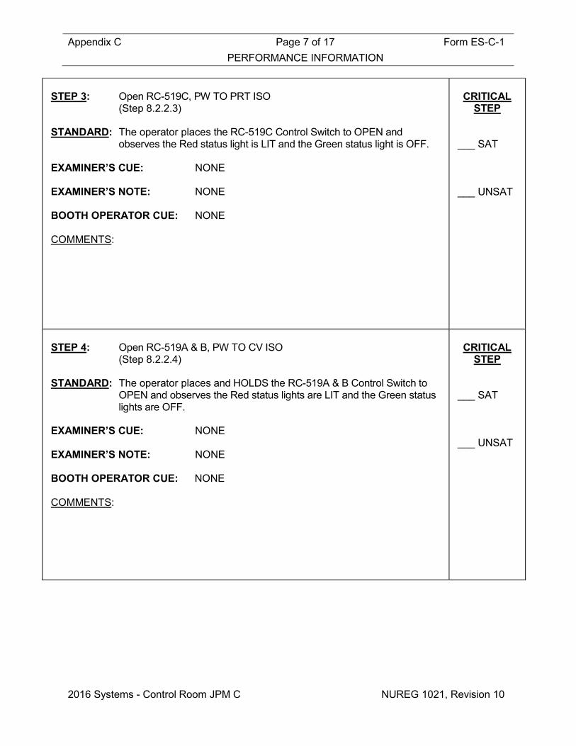
STEP 3: Open RC-519C, PW TO PRT ISO
(Step 8.2.2.3) STANDARD: The operator places the RC-519C Control Switch to OPEN and
observes the Red status light is LIT and the Green status light is OFF. EXAMINER’S CUE: NONE EXAMINER’S NOTE: NONE BOOTH OPERATOR CUE: NONE COMMENTS:
CRITICAL
STEP ___ SAT ___ UNSAT
STEP 4: Open RC-519A & B, PW TO CV ISO
(Step 8.2.2.4) STANDARD: The operator places and HOLDS the RC-519A & B Control Switch to
OPEN and observes the Red status lights are LIT and the Green status lights are OFF.
EXAMINER’S CUE: NONE EXAMINER’S NOTE: NONE BOOTH OPERATOR CUE: NONE COMMENTS:
CRITICAL
STEP ___ SAT ___ UNSAT

Appendix C Page 8 of 17 Form ES-C-1 PERFORMANCE INFORMATION
2016 Systems - Control Room JPM C NUREG 1021, Revision 10
STEP 5: Monitor PRT for rising level
(Step 8.2.2.5) STANDARD: The operator observes rising PRT level on LI-470 or ERFIS. EXAMINER’S CUE: NONE EXAMINER’S NOTE: The normal PRT Level band is 70-80%. It is expected that APP-003-C3, PRT HI PRESS, is
an expected alarm during this evolution. BOOTH OPERATOR CUE: NONE COMMENTS:
___ SAT ___ UNSAT
STEP 6: IF the expected rise in level does NOT occur, THEN stop filling AND
investigate. (Step 8.2.2.6)
STANDARD: The operator observes rising PRT level on LI-470 or ERFIS. EXAMINER’S CUE: NONE EXAMINER’S NOTE: The normal PRT Level band is 70-80%. It is expected that APP-003-C3, PRT HI PRESS, is
an expected alarm during this evolution. BOOTH OPERATOR CUE: NONE COMMENTS:
___ SAT ___ UNSAT
Appendix C Page 9 of 17 Form ES-C-1 PERFORMANCE INFORMATION
2016 Systems - Control Room JPM C NUREG 1021, Revision 10
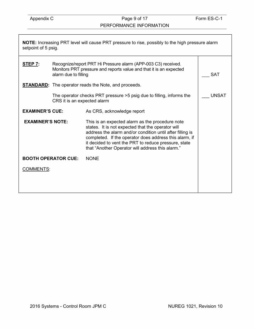
NOTE: Increasing PRT level will cause PRT pressure to rise, possibly to the high pressure alarm setpoint of 5 psig. STEP 7: Recognize/report PRT Hi Pressure alarm (APP-003 C3) received.
Monitors PRT pressure and reports value and that it is an expected alarm due to filling
STANDARD: The operator reads the Note, and proceeds. The operator checks PRT pressure >5 psig due to filling, informs the
CRS it is an expected alarm EXAMINER’S CUE: As CRS, acknowledge report EXAMINER’S NOTE: This is an expected alarm as the procedure note
states. It is not expected that the operator will address the alarm and/or condition until after filling is completed. If the operator does address this alarm, if it decided to vent the PRT to reduce pressure, state that “Another Operator will address this alarm.”
BOOTH OPERATOR CUE: NONE COMMENTS:
___ SAT ___ UNSAT

Appendix C Page 10 of 17 Form ES-C-1 PERFORMANCE INFORMATION
2016 Systems - Control Room JPM C NUREG 1021, Revision 10
STEP 8: WHEN PRT level is between 70% and 80%, THEN perform the
following: a. Stop the Primary Water Pump b. Verify one Primary Water pump is in AUTO.
(Step 8.2.2.7a&b) STANDARD: If the “A” Primary Water Pump was previously started, the operator
places the “A” Primary Water Pump Control Switch to STOP and observes the Green status light is LIT and the Red status light is OFF.
The operator places the “A” Primary Water Pump Control Switch to
AUTO. OR If the “B” Primary Water Pump was previously started, the operator
places the “B” Primary Water Pump Control Switch to STOP and observes the Green status light is LIT and the Red status light is OFF.
EXAMINER’S CUE: NONE EXAMINER’S NOTE: NONE BOOTH OPERATOR CUE: NONE COMMENTS:
___ SAT ___ UNSAT
Appendix C Page 11 of 17 Form ES-C-1 PERFORMANCE INFORMATION
2016 Systems - Control Room JPM C NUREG 1021, Revision 10
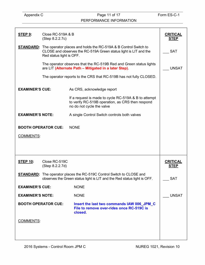
STEP 9: Close RC-519A & B
(Step 8.2.2.7c) STANDARD: The operator places and holds the RC-519A & B Control Switch to
CLOSE and observes the RC-519A Green status light is LIT and the Red status light is OFF.
The operator observes that the RC-519B Red and Green status lights
are LIT (Alternate Path – Mitigated in a later Step). The operator reports to the CRS that RC-519B has not fully CLOSED. EXAMINER’S CUE: As CRS, acknowledge report If a request is made to cycle RC-519A & B to attempt
to verify RC-519B operation, as CRS then respond no do not cycle the valve
EXAMINER’S NOTE: A single Control Switch controls both valves BOOTH OPERATOR CUE: NONE COMMENTS:
CRITICAL
STEP ___ SAT ___ UNSAT
STEP 10: Close RC-519C
(Step 8.2.2.7d) STANDARD: The operator places the RC-519C Control Switch to CLOSE and
observes the Green status light is LIT and the Red status light is OFF. EXAMINER’S CUE: NONE EXAMINER’S NOTE: NONE BOOTH OPERATOR CUE: Insert the last two commands IAW 006_JPM_C
File to remove over-rides once RC-519C is closed.
COMMENTS:
CRITICAL
STEP ___ SAT ___ UNSAT
Appendix C Page 12 of 17 Form ES-C-1 PERFORMANCE INFORMATION
2016 Systems - Control Room JPM C NUREG 1021, Revision 10
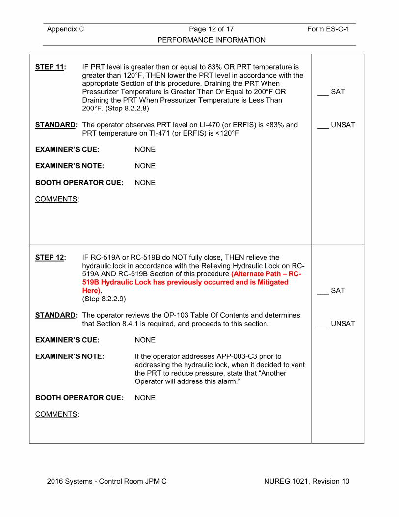
STEP 11: IF PRT level is greater than or equal to 83% OR PRT temperature is
greater than 120°F, THEN lower the PRT level in accordance with the appropriate Section of this procedure, Draining the PRT When Pressurizer Temperature is Greater Than Or Equal to 200°F OR Draining the PRT When Pressurizer Temperature is Less Than 200°F. (Step 8.2.2.8)
STANDARD: The operator observes PRT level on LI-470 (or ERFIS) is <83% and
PRT temperature on TI-471 (or ERFIS) is <120°F EXAMINER’S CUE: NONE EXAMINER’S NOTE: NONE BOOTH OPERATOR CUE: NONE COMMENTS:
___ SAT ___ UNSAT
STEP 12: IF RC-519A or RC-519B do NOT fully close, THEN relieve the
hydraulic lock in accordance with the Relieving Hydraulic Lock on RC-519A AND RC-519B Section of this procedure (Alternate Path – RC-519B Hydraulic Lock has previously occurred and is Mitigated Here). (Step 8.2.2.9)
STANDARD: The operator reviews the OP-103 Table Of Contents and determines
that Section 8.4.1 is required, and proceeds to this section. EXAMINER’S CUE: NONE EXAMINER’S NOTE: If the operator addresses APP-003-C3 prior to
addressing the hydraulic lock, when it decided to vent the PRT to reduce pressure, state that “Another Operator will address this alarm.”
BOOTH OPERATOR CUE: NONE COMMENTS:
___ SAT ___ UNSAT

Appendix C Page 13 of 17 Form ES-C-1 PERFORMANCE INFORMATION
2016 Systems - Control Room JPM C NUREG 1021, Revision 10
NOTE: The RCS System Engineer WILL need to be NOTIFIED WHEN the following section is PERFORMED to relieve hydraulic lock on RC-519A AND RC-519B for Engineering Trending Purposes. STEP 13: Relieving Hydraulic Lock on RC-519A AND RC-519B: Verify the following initial conditions are satisfied:
a. RC-519A & B, PW TO CV ISO, control switch is in the CLOSE position and one OR both valves indicate in mid position. (Step 8.4.1.a)
STANDARD: The operator reads the Note, and proceeds. The operator observes the RC-519A Green status light is LIT and the
Red status light is OFF. The operator observes the RC-519B Red and Green status lights are
LIT. EXAMINER’S CUE: If the operator notifies the CRS or the System
Engineer, acknowledge as the CRS. EXAMINER’S NOTE: NONE BOOTH OPERATOR CUE: NONE COMMENTS:
___ SAT ___ UNSAT

Appendix C Page 14 of 17 Form ES-C-1 PERFORMANCE INFORMATION
2016 Systems - Control Room JPM C NUREG 1021, Revision 10
STEP 14: Verify the Post Accident Sampling System is NOT in operation.
(Step 8.4.1.b) STANDARD: Operator verifies PASS is not operating EXAMINER’S CUE: If asked about the status of this system, ask the
operator what they would expect the status to be in the current plant condition. THEN, indicate that the system is as expected.
EXAMINER’S NOTE: The PASS is ONLY operated under accident
conditions, which do NOT exist. BOOTH OPERATOR CUE: NONE COMMENTS:
___ SAT ___ UNSAT
STEP 15: IF RC-519B is indicating in mid position, THEN cycle RC-519C, PW
TO PRT ISO (Step 8.4.2)
STANDARD: The operator places the RC-519C Control Switch to OPEN and
observes the Red status light is LIT and the Green status light is OFF. The operator places the RC-519C Control Switch to CLOSE and
observes the Green status light is LIT and the Red status light is OFF. The operator observes the RC-519B Green status light is LIT and the
Red status light is OFF. EXAMINER’S CUE: If the operator informs the CRS of the valve position
change, acknowledge as the CRS. EXAMINER’S NOTE: NONE BOOTH OPERATOR CUE: NONE COMMENTS:
CRITICAL
STEP ___ SAT ___ UNSAT

Appendix C Page 15 of 17 Form ES-C-1 PERFORMANCE INFORMATION
2016 Systems - Control Room JPM C NUREG 1021, Revision 10
STEP 16: IF RC-519A is indicating in mid position, THEN perform the following:
a. Verify neither Primary Water Pump is OPERATING. b. Close breaker 15 on Power Panel 27. c. Open HCV-4176, CDT ISOLATION. d. Open HCV-4174, PZR RELIEF TANK ISOLATION. e. Close HCV-4176, CDT ISOLATION. f. Close HCV-4174, PZR RELIEF TANK ISOLATION. g. Open breaker 15 on Power Panel 27.
(Step 8.4.1.3)
STANDARD: The operator recognizes the sub-steps under Section 8.4.1.3 are not applicable and annotates the steps with “N/A”
EXAMINER’S CUE: NONE EXAMINER’S NOTE: NONE BOOTH OPERATOR CUE: NONE COMMENTS:
___ SAT ___ UNSAT
NOTE: Power Panel 27 is located on the west side of the PASS panel. STEP 17: IF RC-519A OR RC-519B is still indicating mid position, THEN
declare the valve out of service AND refer to ITS LCO 3.6.3. (Step 8.4.1.4)
STANDARD: The operator reads the Note, and proceeds. The operator recognizes this step is N/A and marks it N/A EXAMINER’S CUE: Inform the operator you will have another operator
restore PRT pressure to normal EXAMINER’S NOTE: NONE BOOTH OPERATOR CUE: NONE COMMENTS:
___ SAT ___ UNSAT
Terminating Cue: Evaluation on this JPM is complete. STOP TIME:

Appendix C Page 16 of 17 Form ES-C-1 VERIFICATION OF COMPLETION
2016 Systems - Control Room JPM C NUREG 1021, Revision 10
Job Performance Measure No.: 2016 Systems - Control Room JPM C
Examinee’s Name:
Date Performed:
Facility Evaluator:
Number of Attempts:
Time to Complete:
Question Documentation:
Result: SAT UNSAT Examiner’s Signature: Date:
Appendix C Form ES-C-1 JPM CUE SHEET
NUREG 1021, Revision 10
INITIAL CONDITIONS: • The plant is at 100% power.
• APP-003-D3, PRT HI/LO LEVEL, has alarmed.
• The cause of the low level is known leakage from the PRT to the RCDT.
• PRT level is stable at 67%. INITIATING CUE: • The CRS has directed you to restore PRT level to normal IAW
OP-103, Pressurizer Relief Tank Control System. • All of the prerequisites of Section 4.0 are complete.

Appendix C Job Performance Measure Form ES-C-1 Worksheet
2016 Systems - Control Room JPM D (Rev_011216) NUREG 1021, Revision 10
SIM JPM D Developed By: ______________________________ Date: ___________ Instructor/Developer Concurred By: ______________________________ Date: ___________ Line Superintendent/Supervisor SRO Approved By: ______________________________ Date: ___________ Superintendent/Supervisor Training

Appendix C Page 2 of 13 Form ES-C-1 Job Performance Measure Worksheet
2016 Systems - Control Room JPM D NUREG 1021, Revision 10
Facility: HB Robinson Task No.: Task Title: Reactor Startup with Ejected Control
Rod JPM No.: 2016 Systems - Control
Room JPM D (Alternate Path)
K/A Reference: 001 A1.06 (4.1/4.4) Examinee: NRC Examiner:
Facility Evaluator: Date:
Method of testing:
Simulated Performance: Actual Performance: X Classroom Simulator X Plant
READ TO THE EXAMINEE
I will explain the initial conditions, which steps to simulate or discuss, and provide initiating cues. When you complete the task successfully, the objective for this Job Performance Measure will be satisfied.
Provide Operator with Initial Conditions/Cue (Last Page of this JPM), and Handout 1. Initial Conditions: • The plant is stabilized at 2% power. • The RCS is at normal operating temperature and pressure. • A plant startup is in progress IAW GP-003, Normal Plant Startup
From Hot Shutdown to Critical, and complete through Step 8.4.7. • You are the OATC. • The BOP is temporarily outside the Control Room. Initiating Cue: The CRS has directed you to pull control rods to stabilize reactor power
between 3-5% by continuing with Step 8.4.8 of GP-003. Task Standard: The operator will start to raise reactor power to 3-5%. Then, the operator
will manually trip the reactor, attempt to manually actuate Safety Injection and manually start SI Pumps in response to an ejected rod.
Required Materials: None General References: GP-003 (Normal Plant Startup From Hot Shutdown to Critical), Rev 105

Appendix C Page 3 of 13 Form ES-C-1 Job Performance Measure Worksheet
2016 Systems - Control Room JPM D NUREG 1021, Revision 10
APP-004 (First Out Reactor Trips), Rev 18 EOP-E-0 (Reactor Trip or Safety Injection), Rev 6 AOP-001 (Malfunction of Reactor Control System), Rev 33 AOP-016 (Excessive Primary Plant Leakage), Rev 23 AOP-019 (Malfunction of RCS Pressure Control), Rev 20 EOP-E-0 (Reactor Trip or Safety Injection), Rev 6 OMM-022 (Emergency Operating Procedures User’s Guide), Rev 45 Handouts: Handout 1: Section 8.4 of GP-003 marked up for this JPM to Step 8.4.7. Time Critical Task: NO Validation Time: 5 minutes NOTE: This JPM should be pre-briefed in the Briefing Room.
Critical Step Justification
Step 1 This step is critical because placing the Manual Rod Control Switch to the OUT
position is necessary to raise and then stabilize power between 3-5%. Step 2 This step is critical because pressing one of two Rx Trip pushbuttons is necessary
to manually trip the reactor. Step 8 This step is critical because pressing BOTH SI pushbuttons is necessary to
manually attempt to actuate SI.
Alternate Path Critical Step Justification
Step 9 This step is critical because placing the “A” and the “C” SI Pump Control Switches
to START is necessary to manually start SI Pumps in response to an ejected rod.

Appendix C Page 4 of 13 Form ES-C-1 Job Performance Measure Worksheet
2016 Systems - Control Room JPM D NUREG 1021, Revision 10
SIMULATOR OPERATIONAL GUIDELINES 1. Construct Scenario File 006_JPM_ D as follows:
• IMF SIS01A, f:FAIL_TO_INITIATE, (SI Train “A” Fails to AUTO/MANUAL actuate) • IMF SIS01B, f:FAIL_TO_INITIATE, (SI Train “A” Fails to AUTO/MANUAL actuate) • IMF RPS01A f:FAILURE_TO_OPEN, AUTO • IMF RPS01B f:FAILURE_TO_OPEN, AUTO
• Event 1: $006_ROD_OUT_ARMED IMF CRF05A d:5 f:2000, H-8 (Ejected Control Rod)
2. Reset simulator to IC-1, 10-8amps IR and raise power to 2% and stabilize. 3. Place in RUN, execute Scenario File 006_JPM_D and allow time to stabilize. 4. Ensure actions of GP-003 up to Step 8.4.7 are complete. 5. Stabilize the plant. 6. Freeze the Simulator. OR 1. Reset Simulator to Temporary Snap IC-603 (August, 2015). 2. Scenario File 006_JPM_ D
3. Perform Attachment 2 (Simulator Setup For Exams) of TAP-411. 4. Place Simulator in Run when Operator assumes the watch.

Appendix C Page 5 of 13 Form ES-C-1 PERFORMANCE INFORMATION
2016 Systems - Control Room JPM D NUREG 1021, Revision 10
(Critical Steps are identified as such in right-hand column) Provide Operator with Initial Conditions/Cue (Last Page of this JPM), and Handout 1. START TIME:
STEP 1: ADJUST control rods as necessary to achieve the following while
continuing with this procedure:
RCS Tavg between 547°F and 551°F Reactor Power 3% to less than or equal to 5%. (Step 8.4.8).
STANDARD: The operator places the Manual Rod Control Switch to the OUT
position to raise reactor power between 3-5%, and Tavg between 547°F and 551°F.
The operator will observe that an event unrelated to the reactor
startup is occurring. EXAMINER’S CUE: NONE EXAMINER’S NOTE: An Ejected Rod will occur shortly after the rod
withdrawal has commenced. Shortly afterwards, the following indications will be
available to the operator: • Several RTGB Annunciators alarm • Rod Bottom light for Control Rod H-8 is LIT • SUR is positive and rising • Neutron flux is rising • RCS pressure is lowering • Pzr level is lowering • Charging Pump speed is rising
COMMENTS:
CRITICAL
STEP ___ SAT ___ UNSAT

Appendix C Page 6 of 13 Form ES-C-1 PERFORMANCE INFORMATION
2016 Systems - Control Room JPM D NUREG 1021, Revision 10
STEP 2: Diagnose LOCA and manually trip Rx
STANDARD: The operator observes RTGB alarms and indications and manually
trips the Rx by pressing one of two Rx Trip pushbuttons. The operator proceeds to EOP-E-0. EXAMINER’S CUE: NONE EXAMINER’S NOTE: The operator may address one or more APPs, enter
AOP-001, AOP-016, or AOP-019. The operator may manually trip the reactor based on
Attachment 3, Control Band and Trip Limit Guidance, of OMM-022, Emergency Operating Procedures User’s Guide.
Since the first four actions of EOP-E-0 are Immediate
Actions, the operator will likely NOT address the procedure (EOP-E-0) until the Immediate Actions are complete.
BOOTH OPERATOR CUE: NONE COMMENTS:
CRITICAL
STEP ___ SAT ___ UNSAT

Appendix C Page 7 of 13 Form ES-C-1 PERFORMANCE INFORMATION
2016 Systems - Control Room JPM D NUREG 1021, Revision 10
STEP 3: CHECK Reactor Trip:
Reactor Trip AND Bypass Breakers ‑ OPEN Rod position indicators ‑ FULLY INSERTED Rod Bottom Lights ‑ ILLUMINATED Neutron Flux ‑ LOWERING (EOP-E-0 Step 1)
STANDARD: The operator observes parameters and determines that the Rx is
tripped. EXAMINER’S CUE: NONE EXAMINER’S NOTE: NONE BOOTH OPERATOR CUE: NONE COMMENTS:
___ SAT ___ UNSAT
STEP 4: CHECK Turbine Trip:
Both Turbine Stop Valves ‑ CLOSED All MSR Purge AND Shutoff Valves ‑ CLOSED (EOP-E-0 Step 2)
STANDARD: The operator observes parameters and determines that the Turbine
is tripped. EXAMINER’S CUE: NONE EXAMINER’S NOTE: NONE BOOTH OPERATOR CUE: NONE COMMENTS:
___ SAT ___ UNSAT

Appendix C Page 8 of 13 Form ES-C-1 PERFORMANCE INFORMATION
2016 Systems - Control Room JPM D NUREG 1021, Revision 10
STEP 5: CHECK Power To AC EMERGENCY BUSSES:
CHECK Bus E‑1 OR E‑2 ‑ AT LEAST ONE ENERGIZED CHECK Bus E‑1 AND E‑2 ‑ BOTH ENERGIZED (EOP-E-0 Step 3)
STANDARD: The operator observes E-1/E-2 bus voltage and determines that
both E-1 and E-2 are energized. EXAMINER’S CUE: NONE EXAMINER’S NOTE: NONE BOOTH OPERATOR CUE: NONE COMMENTS:
___ SAT ___ UNSAT
STEP 6: CHECK SI Status:
CHECK if SI is actuated: SI annunciators ‑ ANY ILLUMINATED OR SI equipment ‑ AUTO STARTED
(EOP-E-0 Step 4/4.a) STANDARD: The operator observes SI annunciators are LIT, and proceeds. EXAMINER’S CUE: NONE EXAMINER’S NOTE: If the SI annunciators are not lit, the operator will
perform the step 4.a RNO (It is expected that the criteria to automatically actuate safety injection will either occur or be close to occurring during the performance of this step).
SI equipment will NOT auto start. BOOTH OPERATOR CUE: NONE COMMENTS:
___ SAT ___ UNSAT
Appendix C Page 9 of 13 Form ES-C-1 PERFORMANCE INFORMATION
2016 Systems - Control Room JPM D NUREG 1021, Revision 10
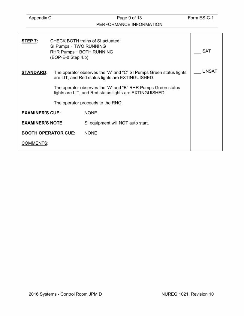
STEP 7: CHECK BOTH trains of SI actuated: SI Pumps ‑ TWO RUNNING
RHR Pumps ‑ BOTH RUNNING (EOP-E-0 Step 4.b)
STANDARD: The operator observes the “A” and “C” SI Pumps Green status lights
are LIT, and Red status lights are EXTINGUISHED. The operator observes the “A” and “B” RHR Pumps Green status
lights are LIT, and Red status lights are EXTINGUISHED The operator proceeds to the RNO. EXAMINER’S CUE: NONE EXAMINER’S NOTE: SI equipment will NOT auto start. BOOTH OPERATOR CUE: NONE COMMENTS:
___ SAT ___ UNSAT

Appendix C Page 10 of 13 Form ES-C-1 PERFORMANCE INFORMATION
2016 Systems - Control Room JPM D NUREG 1021, Revision 10
STEP 8: Manually ACTUATE SI by depressing BOTH SI pushbuttons. (EOP-E-0 Step 4.b RNO)
STANDARD: The operator presses BOTH SI pushbuttons. The operator observes the “A” and “C” SI Pumps Green status lights
are LIT, and Red status lights are EXTINGUISHED. The operator observes the “A” and “B” RHR Pumps Green status
lights are LIT, and Red status lights are EXTINGUISHED. (Alternate Path).
EXAMINER’S CUE: NONE EXAMINER’S NOTE: Upon completion of the EOP-E-0 Immediate Actions
the operator may obtain EOP-E-0 and verify the Immediate Actions, BEFORE proceeding.
If so, the operator will likely review the EOP-E-0
Foldout Page, as well. BOOTH OPERATOR CUE: NONE COMMENTS:
CRITICAL
STEP ___ SAT ___ UNSAT

Appendix C Page 11 of 13 Form ES-C-1 PERFORMANCE INFORMATION
2016 Systems - Control Room JPM D NUREG 1021, Revision 10
STEP 9: Manually start both SI Pumps. (Step 5.3.1.c of OMM-022)
STANDARD: The operator places the “A” SI Pump Control Switch to Start and
observes the Red status lights are LIT, and Green status lights are EXTINGUISHED.
The operator places the “C” SI Pump Control Switch to Start and
observes the Red status lights are LIT, and Green status lights are EXTINGUISHED.
EXAMINER’S CUE: NONE EXAMINER’S NOTE: This action may be taken at the time that the
operator realizes that the manual SI actuation pushbuttons have failed to start the SI equipment using the guidance for Prompt and Prudent actions in OMM-022, Step 5.3.1.c. (Prompt action is necessary to prevent the deterioration of plant conditions or components to a possibly unsafe or unstable level. If time permits, approval from the SM/CRS shall be obtained. Factors to consider include: complexity of action, potential for damage from common cause, etc. Examples include: Failure of automatic systems to perform or respond correctly.)
If the operator addresses EOP-E-0 to verify the
Immediate Actions upon completion of Step 4, and the SI Pumps have NOT been started, the operator will address Attachment 1 (With the BOP out of the Control Room) and manually start the SI Pumps (Step 1 and Step 1 RNO).
BOOTH OPERATOR CUE: NONE COMMENTS:
CRITICAL STEP
___ SAT ___ UNSAT
Terminating Cue: Evaluation on this JPM is complete. STOP TIME:

Appendix C Page 12 of 13 Form ES-C-1 VERIFICATION OF COMPLETION
2016 Systems - Control Room JPM D NUREG 1021, Revision 10
Job Performance Measure No.: 2016 Systems - Control Room JPM D
Examinee’s Name:
Date Performed:
Facility Evaluator:
Number of Attempts:
Time to Complete:
Question Documentation:
Result: SAT UNSAT Examiner’s Signature: Date:

Appendix C Form ES-C-1 JPM CUE SHEET
NUREG 1021, Revision 10
INITIAL CONDITIONS: • The plant is stabilized at 2% power.
• The RCS is at normal operating temperature and pressure.
• A plant startup is in progress IAW GP-003, Normal Plant Startup From Hot Shutdown to Critical, and complete through Step 8.4.7.
• You are the OATC.
• The BOP is temporarily outside the Control Room. INITIATING CUE: The CRS has directed you to pull control rods to stabilize reactor
power between 3-5% by continuing with Step 8.4.8 of GP-003.
Appendix C Job Performance Measure Form ES-C-1 Worksheet
2016 Systems - Control Room JPM E (Rev_011116) NUREG 1021, Revision 10
SIM JPM E Developed By: ______________________________ Date: ___________ Instructor/Developer Concurred By: ______________________________ Date: ___________ Line Superintendent/Supervisor SRO Approved By: ______________________________ Date: ___________ Superintendent/Supervisor Training
Appendix C Page 2 of 18 Form ES-C-1 Job Performance Measure Worksheet
2016 Systems - Control Room JPM E NUREG 1021, Revision 10
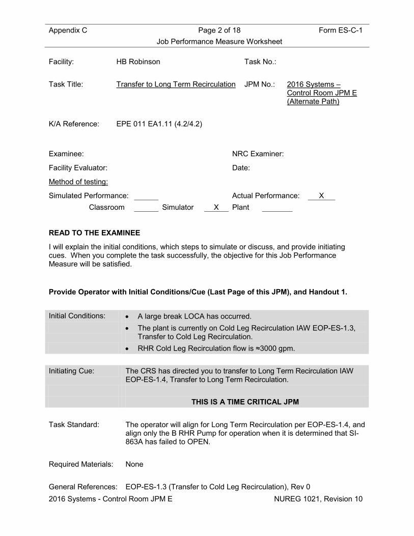
Facility: HB Robinson Task No.: Task Title: Transfer to Long Term Recirculation JPM No.: 2016 Systems –
Control Room JPM E (Alternate Path)
K/A Reference: EPE 011 EA1.11 (4.2/4.2) Examinee: NRC Examiner:
Facility Evaluator: Date:
Method of testing:
Simulated Performance: Actual Performance: X Classroom Simulator X Plant
READ TO THE EXAMINEE
I will explain the initial conditions, which steps to simulate or discuss, and provide initiating cues. When you complete the task successfully, the objective for this Job Performance Measure will be satisfied.
Provide Operator with Initial Conditions/Cue (Last Page of this JPM), and Handout 1. Initial Conditions: • A large break LOCA has occurred. • The plant is currently on Cold Leg Recirculation IAW EOP-ES-1.3,
Transfer to Cold Leg Recirculation. • RHR Cold Leg Recirculation flow is ≈3000 gpm. Initiating Cue: The CRS has directed you to transfer to Long Term Recirculation IAW
EOP-ES-1.4, Transfer to Long Term Recirculation. THIS IS A TIME CRITICAL JPM Task Standard: The operator will align for Long Term Recirculation per EOP-ES-1.4, and
align only the B RHR Pump for operation when it is determined that SI-863A has failed to OPEN.
Required Materials: None General References: EOP-ES-1.3 (Transfer to Cold Leg Recirculation), Rev 0
Appendix C Page 3 of 18 Form ES-C-1 Job Performance Measure Worksheet
2016 Systems - Control Room JPM E NUREG 1021, Revision 10
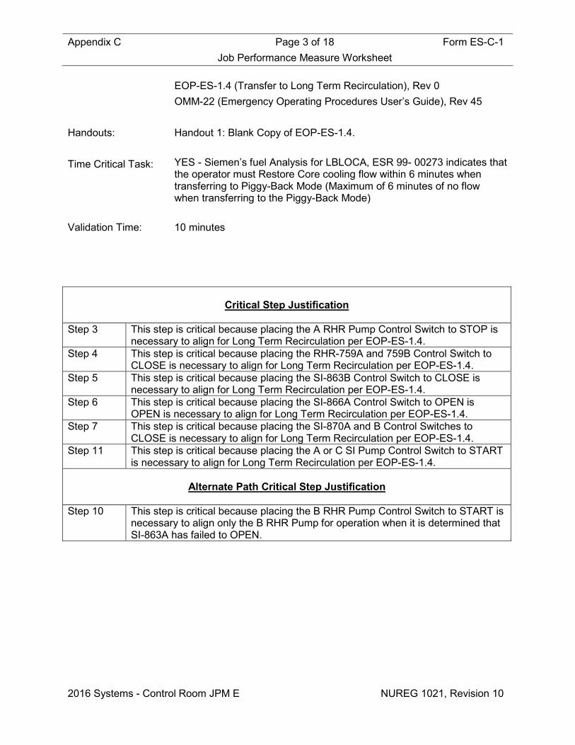
EOP-ES-1.4 (Transfer to Long Term Recirculation), Rev 0 OMM-22 (Emergency Operating Procedures User’s Guide), Rev 45 Handouts: Handout 1: Blank Copy of EOP-ES-1.4. Time Critical Task: YES - Siemen’s fuel Analysis for LBLOCA, ESR 99- 00273 indicates that
the operator must Restore Core cooling flow within 6 minutes when transferring to Piggy-Back Mode (Maximum of 6 minutes of no flow when transferring to the Piggy-Back Mode)
Validation Time: 10 minutes
Critical Step Justification
Step 3 This step is critical because placing the A RHR Pump Control Switch to STOP is
necessary to align for Long Term Recirculation per EOP-ES-1.4. Step 4 This step is critical because placing the RHR-759A and 759B Control Switch to
CLOSE is necessary to align for Long Term Recirculation per EOP-ES-1.4. Step 5 This step is critical because placing the SI-863B Control Switch to CLOSE is
necessary to align for Long Term Recirculation per EOP-ES-1.4. Step 6 This step is critical because placing the SI-866A Control Switch to OPEN is
OPEN is necessary to align for Long Term Recirculation per EOP-ES-1.4. Step 7 This step is critical because placing the SI-870A and B Control Switches to
CLOSE is necessary to align for Long Term Recirculation per EOP-ES-1.4. Step 11 This step is critical because placing the A or C SI Pump Control Switch to START
is necessary to align for Long Term Recirculation per EOP-ES-1.4.
Alternate Path Critical Step Justification
Step 10 This step is critical because placing the B RHR Pump Control Switch to START is necessary to align only the B RHR Pump for operation when it is determined that SI-863A has failed to OPEN.

Appendix C Page 4 of 18 Form ES-C-1 Job Performance Measure Worksheet
2016 Systems - Control Room JPM E NUREG 1021, Revision 10
SIMULATOR OPERATIONAL GUIDELINES 1. Construct Scenario File 006_JPM_ E as follows:
• IOR diSISAAI201 f:CLOSE (RHR Loop Recirc SI-863A fails to OPEN)
2. Reset simulator to IC-28, (Cold Leg Recirculation). 3. Place in RUN, execute Scenario File 006_JPM_E and allow time to stabilize.
4. Perform the following:
• Stop “A” Primary Water Pump and place in AUTO • CLOSE FCV-114A and place in AUTO • Place Controller FCV-114A in AUTO
5. Acknowledge alarms on RR-1 and APP-036. 6. Freeze the Simulator. OR 1. Reset Simulator to Temporary Snap IC-604 (August, 2015). 2. Place Simulator in Run, acknowledge alarms on RR-1 and APP-036, and Freeze Simulator. 3. Perform Attachment 2 (Simulator Setup For Exams) of TAP-411. 4. Place Simulator in Run when operator assumes the watch.
Appendix C Page 5 of 18 Form ES-C-1 PERFORMANCE INFORMATION
2016 Systems - Control Room JPM E NUREG 1021, Revision 10
(Critical Steps are identified as such in right-hand column) Provide Operator with Initial Conditions/Cue (Last Page of this JPM), and Handout 1. START TIME:
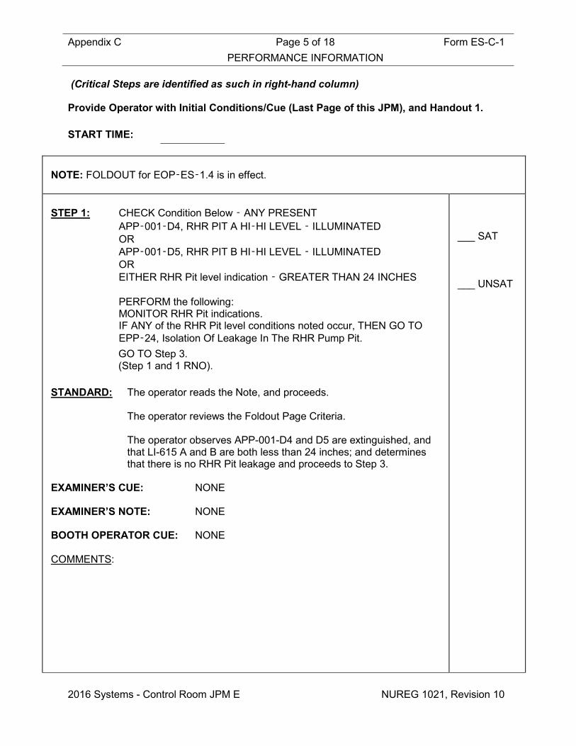
NOTE: FOLDOUT for EOP‑ES‑1.4 is in effect. STEP 1: CHECK Condition Below ‑ ANY PRESENT
APP‑001‑D4, RHR PIT A HI‑HI LEVEL ‑ ILLUMINATED OR APP‑001‑D5, RHR PIT B HI‑HI LEVEL ‑ ILLUMINATED OR EITHER RHR Pit level indication ‑ GREATER THAN 24 INCHES PERFORM the following: MONITOR RHR Pit indications. IF ANY of the RHR Pit level conditions noted occur, THEN GO TO EPP‑24, Isolation Of Leakage In The RHR Pump Pit. GO TO Step 3. (Step 1 and 1 RNO).
STANDARD: The operator reads the Note, and proceeds. The operator reviews the Foldout Page Criteria. The operator observes APP-001-D4 and D5 are extinguished, and
that LI-615 A and B are both less than 24 inches; and determines that there is no RHR Pit leakage and proceeds to Step 3.
EXAMINER’S CUE: NONE EXAMINER’S NOTE: NONE BOOTH OPERATOR CUE: NONE COMMENTS:
___ SAT ___ UNSAT

Appendix C Page 6 of 18 Form ES-C-1 PERFORMANCE INFORMATION
2016 Systems - Control Room JPM E NUREG 1021, Revision 10
STEP 2: DETERMINE Needed RHR Alignment:
CHECK RHR System alignment ‑ IN PIGGY‑BACK MODE
OBSERVE the CAUTION prior to Step 5 AND GO TO Step 5. (Step 3 and 3 RNO.)
STANDARD: The operator observes SI-863A and B Green status lights are LIT,
and Red status lights are OFF (Or equivalent) and determines that RHR is NOT in PIGGY-BACK Mode and proceeds to the Caution prior to Step 5.
EXAMINER’S CUE: NONE EXAMINER’S NOTE: NONE BOOTH OPERATOR CUE: NONE COMMENTS:
___ SAT ___ UNSAT
CAUTION: Steps 5 through 8 must be performed without delay to minimize the time without flow through the core.
Appendix C Page 7 of 18 Form ES-C-1 PERFORMANCE INFORMATION
2016 Systems - Control Room JPM E NUREG 1021, Revision 10
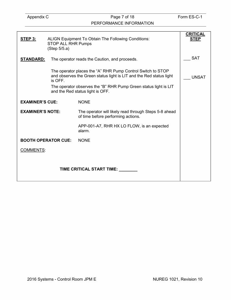
STEP 3: ALIGN Equipment To Obtain The Following Conditions:
STOP ALL RHR Pumps (Step 5/5.a)
STANDARD: The operator reads the Caution, and proceeds. The operator places the “A” RHR Pump Control Switch to STOP
and observes the Green status light is LIT and the Red status light is OFF.
The operator observes the “B” RHR Pump Green status light is LIT and the Red status light is OFF.
EXAMINER’S CUE: NONE EXAMINER’S NOTE: The operator will likely read through Steps 5-8 ahead
of time before performing actions. APP-001-A7, RHR HX LO FLOW, is an expected
alarm. BOOTH OPERATOR CUE: NONE COMMENTS:
TIME CRITICAL START TIME: ________
CRITICAL STEP
___ SAT ___ UNSAT

Appendix C Page 8 of 18 Form ES-C-1 PERFORMANCE INFORMATION
2016 Systems - Control Room JPM E NUREG 1021, Revision 10
STEP 4: ALIGN Equipment To Obtain The Following Conditions:
CLOSE RHR HX Discharge Valves RHR‑759A RHR‑759B (Step 5/5.b)
STANDARD: The operator places the RHR-759A Control Switch to CLOSE and
observes that the Green status light is LIT and the Red status light is OFF.
The operator places the RHR-759B Control Switch to CLOSE and observes that the Green status light is LIT and the Red status light is OFF.
EXAMINER’S CUE: NONE EXAMINER’S NOTE: NONE BOOTH OPERATOR CUE: NONE COMMENTS:
CRITICAL
STEP ___ SAT ___ UNSAT

Appendix C Page 9 of 18 Form ES-C-1 PERFORMANCE INFORMATION
2016 Systems - Control Room JPM E NUREG 1021, Revision 10
STEP 5: ALIGN Equipment To Obtain The Following Conditions:
OPEN RHR Loop Recirc Valves SI‑863A SI‑863B (Step 5/5.c)
STANDARD: The operator places the SI-863A Control Switch to OPEN and
observes that the Green status light remains LIT and the Red status light remains OFF (Alternate Path – mitigated in subsequent steps).
The operator places the SI-863B Control Switch to OPEN and observes that the Red status light is LIT and the Green status light is OFF.
EXAMINER’S CUE: If operator reports the failure of SI-863A to OPEN,
acknowledge as the CRS. EXAMINER’S NOTE: The operator should not stop the procedure, the
procedure is designed to subsequently mitigate the failure of SI-863A to OPEN.
The operator may place the SI-863A Control Switch
back to CLOSE. BOOTH OPERATOR CUE: NONE COMMENTS:
CRITICAL
STEP ___ SAT ___ UNSAT
CAUTION: Opening SI‑866A AND SI‑866B, Hot Leg Injection Valves, with only one SI pump running will result in SI Pump runout.

Appendix C Page 10 of 18 Form ES-C-1 PERFORMANCE INFORMATION
2016 Systems - Control Room JPM E NUREG 1021, Revision 10
STEP 6: ALIGN For Hot Leg Recirculation:
OPEN SI‑866A, LOOP 3 HOT LEG INJ Valve (Step 6/6.a)
STANDARD: The operator reads the Caution, and proceeds. The operator places the key-operated SI-866A Control Switch to
OPEN and observes that SI-866A Red status light is LIT and the Green status light is OFF.
EXAMINER’S CUE: NONE EXAMINER’S NOTE: NONE BOOTH OPERATOR CUE: NONE COMMENTS:
CRITICAL
STEP ___ SAT ___ UNSAT
STEP 7: ALIGN For Hot Leg Recirculation:
CLOSE BIT Outlet Valves: SI‑870A SI‑870B (Step 6/6.b)
STANDARD: The operator places the SI-870A Control Switch to CLOSE, and
observes that the Green status light is LIT and the Red status light is OFF.
The operator places the SI-870B Control Switch to CLOSE, and observes that the Green status light is LIT and the Red status light is OFF.
EXAMINER’S CUE: NONE EXAMINER’S NOTE: NONE BOOTH OPERATOR CUE: NONE COMMENTS:
CRITICAL
STEP ___ SAT ___ UNSAT

Appendix C Page 11 of 18 Form ES-C-1 PERFORMANCE INFORMATION
2016 Systems - Control Room JPM E NUREG 1021, Revision 10
CAUTION: RHR‑759A AND RHR‑759B, RHR HX Discharge Valves, are closed. The RHR Pumps will run dead‑headed AND are subject to damage UNTIL the SI pumps are started. STEP 8: ESTABLISH Hot Leg Recirculation Flow:
CHECK RHR‑759A, RHR HX A DISCH Valve ‑ CLOSED (Step 7/7.a)
STANDARD: The operator reads the Caution, and proceeds. The operator observes the RHR-759A Green status light is LIT, and
Red status light is OFF. EXAMINER’S CUE: NONE EXAMINER’S NOTE: NONE BOOTH OPERATOR CUE: NONE COMMENTS:
___ SAT ___ UNSAT
STEP 9: ESTABLISH Hot Leg Recirculation Flow:
CHECK SI‑863A, RHR LOOP RECIRC Valve ‑ OPEN (Step 7/7.b)
STANDARD: The operator observes the SI-863A Green status light is LIT and
determines that SI-863A is CLOSED (Alternate Path), and proceeds to Step 7.b RNO.
EXAMINER’S CUE: NONE EXAMINER’S NOTE: The operator has previously attempted to OPEN this
valve, and it failed to OPEN. This procedure will address the compensatory actions now.
BOOTH OPERATOR CUE: NONE COMMENTS:
___ SAT ___ UNSAT
Appendix C Page 12 of 18 Form ES-C-1 PERFORMANCE INFORMATION
2016 Systems - Control Room JPM E NUREG 1021, Revision 10
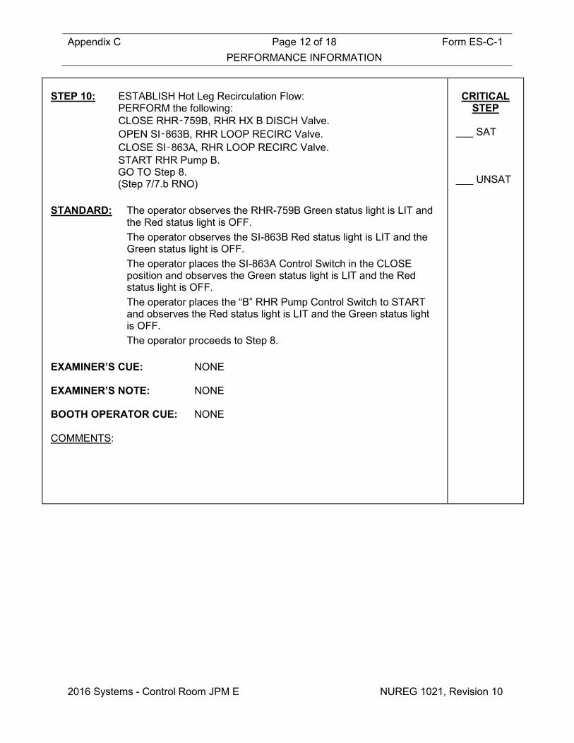
STEP 10: ESTABLISH Hot Leg Recirculation Flow:
PERFORM the following: CLOSE RHR‑759B, RHR HX B DISCH Valve. OPEN SI‑863B, RHR LOOP RECIRC Valve. CLOSE SI‑863A, RHR LOOP RECIRC Valve. START RHR Pump B. GO TO Step 8. (Step 7/7.b RNO)
STANDARD: The operator observes the RHR-759B Green status light is LIT and
the Red status light is OFF. The operator observes the SI-863B Red status light is LIT and the
Green status light is OFF. The operator places the SI-863A Control Switch in the CLOSE
position and observes the Green status light is LIT and the Red status light is OFF.
The operator places the “B” RHR Pump Control Switch to START and observes the Red status light is LIT and the Green status light is OFF.
The operator proceeds to Step 8. EXAMINER’S CUE: NONE EXAMINER’S NOTE: NONE BOOTH OPERATOR CUE: NONE COMMENTS:
CRITICAL
STEP ___ SAT ___ UNSAT

Appendix C Page 13 of 18 Form ES-C-1 PERFORMANCE INFORMATION
2016 Systems - Control Room JPM E NUREG 1021, Revision 10
STEP 11: START One SI Pump (Step 8) STANDARD: The operator places the “A” or “C” SI Pump Control Switch to
START, and observes the Red status light is LIT and the Green status light is OFF.
EXAMINER’S CUE: NONE EXAMINER’S NOTE: NONE BOOTH OPERATOR CUE: NONE COMMENTS:
TIME CRITICAL STOP TIME: ________ (Less than 6 Minutes)
CRITICAL STEP
___ SAT ___ UNSAT
STEP 12: CHECK Indicated Flow On The Appropriate Flow Meters:
PATH FLOW METERS SI-866B FI-940, SI Hot Leg Header Flow
FI-933, SI Loop 2 Hot Leg Flow SI-866A FI-940, SI Hot Leg Header Flow
FI-932, SI Loop 3 Hot Leg Flow (Step 9)
STANDARD: The operator observes FI-940 and determines flow to be 640-680
gpm. The operator observes FI-932 and determines flow to be 580-600
gpm. EXAMINER’S CUE: NONE EXAMINER’S NOTE: NONE BOOTH OPERATOR CUE: NONE COMMENTS:
___ SAT ___ UNSAT

Appendix C Page 14 of 18 Form ES-C-1 PERFORMANCE INFORMATION
2016 Systems - Control Room JPM E NUREG 1021, Revision 10
CAUTION: The operator should be sure that cavitation is taking place prior to transitioning to steps that attempt to mitigate screen blockage. The actions taken are beyond design basis AND should NOT be taken unless warranted. Stable indication on FI‑605 may also be used as an aid in determining if cavitation is present in subsequent steps when RHR‑759A OR RHR‑759B AND RHR‑
744A OR RHR‑744B are open. STEP 13: CHECK RHR Pump Discharge Pressure ‑ STABLE PI‑602A
PI‑602B (Step 10)
STANDARD: The operator reads the caution, and proceeds. The operator observes PI-602B to be ≈160 psig. EXAMINER’S CUE: NONE EXAMINER’S NOTE: NONE BOOTH OPERATOR CUE: NONE COMMENTS:
___ SAT ___ UNSAT

Appendix C Page 15 of 18 Form ES-C-1 PERFORMANCE INFORMATION
2016 Systems - Control Room JPM E NUREG 1021, Revision 10
STEP 14: DETERMINE If Flow Should Be Established To Cold Legs as follows:
CHECK RCS pressure ‑ LESS THAN 275 PSIG CHECK RHR Cold Leg Recirculation flow indicated in EOP‑ES‑1.3, Transfer To Cold Leg Recirculation CHECK CV Sump Screen status ‑ HAS REMAINED CLEAR DURING RECIRCULATION CHECK ALL of the following ‑ AVAILABLE
• FI‑605, RHR TOTAL FLOW • RHR‑759A AND RHR‑759B, RHR HX Discharge Valves • SI‑863A AND SI‑863B, RHR LOOP RECIRC Valves • RHR Pumps A AND B
(Step 11a-d and 11.d RNO) STANDARD: The operator observes PR-444 (or equivalent) to be 5 psig. The operator recalls that 3000 gpm of flow existed in the Cold Legs
before this procedure started. The operator observes RHR discharge pressure to be steady at 150
psig (or equivalent), and determines that no RHR Pump cavitation is occurring.
The operator observes 0 gpm on FI-605. The operator observes the RHR-759A Green status light is LIT, and
the Red status light is OFF. The operator observes the RHR-759B Green status light is LIT, and
the Red status light is OFF. The operator observes the SI-863B Red status light is LIT and the
Green status light is OFF. The operator observes the SI-863A Green status light is LIT and the
Red status light is OFF. The operator recognizes that SI-863A is NOT available, and
proceeds to Step 16. EXAMINER’S CUE: NONE EXAMINER’S NOTE: NONE BOOTH OPERATOR CUE: NONE COMMENTS:
___ SAT ___ UNSAT
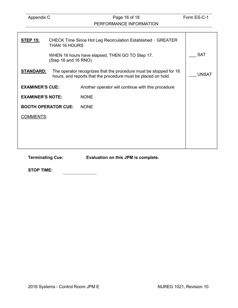
Appendix C Page 16 of 18 Form ES-C-1 PERFORMANCE INFORMATION
2016 Systems - Control Room JPM E NUREG 1021, Revision 10
STEP 15: CHECK Time Since Hot Leg Recirculation Established ‑ GREATER
THAN 16 HOURS WHEN 16 hours have elapsed, THEN GO TO Step 17.
(Step 16 and 16 RNO) STANDARD: The operator recognizes that the procedure must be stopped for 16
hours, and reports that the procedure must be placed on hold. EXAMINER’S CUE: Another operator will continue with this procedure EXAMINER’S NOTE: NONE BOOTH OPERATOR CUE: NONE COMMENTS:
___ SAT ___ UNSAT
Terminating Cue: Evaluation on this JPM is complete. STOP TIME:
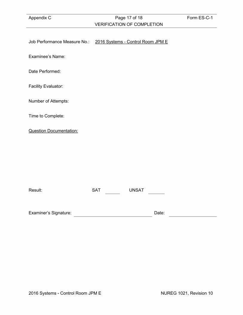
Appendix C Page 17 of 18 Form ES-C-1 VERIFICATION OF COMPLETION
2016 Systems - Control Room JPM E NUREG 1021, Revision 10
Job Performance Measure No.: 2016 Systems - Control Room JPM E
Examinee’s Name:
Date Performed:
Facility Evaluator:
Number of Attempts:
Time to Complete:
Question Documentation:
Result: SAT UNSAT Examiner’s Signature: Date:

Appendix C Form ES-C-1 JPM CUE SHEET
NUREG 1021, Revision 10
INITIAL CONDITIONS: • A large break LOCA has occurred.
• The plant is currently on Cold Leg Recirculation IAW EOP-ES-1.3, Transfer to Cold Leg Recirculation.
• RHR Cold Leg Recirculation flow is ≈3000 gpm. INITIATING CUE: The CRS has directed you to transfer to Long Term Recirculation
IAW EOP-ES-1.4, Transfer to Long Term Recirculation.
THIS IS A TIME CRITICAL JPM

Appendix C Job Performance Measure Form ES-C-1 Worksheet
2016 Systems - Control Room JPM F (Rev_011116) NUREG 1021, Revision 10
SIM JPM F Developed By: ______________________________ Date: ___________ Instructor/Developer Concurred By: ______________________________ Date: ___________ Line Superintendent/Supervisor SRO Approved By: ______________________________ Date: ___________ Superintendent/Supervisor Training

Appendix C Page 2 of 15 Form ES-C-1 Job Performance Measure Worksheet
2016 Systems - Control Room JPM F NUREG 1021, Revision 10
Facility: HB Robinson Task No.: Task Title: Fill a Safety Injection Accumulator JPM No.: 2016 Systems - Control
Room JPM F K/A Reference: 006 A4.02 (4.0/3.8) Examinee: NRC Examiner:
Facility Evaluator: Date:
Method of testing:
Simulated Performance: Actual Performance: X Classroom Simulator X Plant
READ TO THE EXAMINEE
I will explain the initial conditions, which steps to simulate or discuss, and provide initiating cues. When you complete the task successfully, the objective for this Job Performance Measure will be satisfied.
Provide Operator with Initial Conditions/Cue (Last Page of this JPM), and Handout 1. Initial Conditions: • The plant is at 100% power. • SI ACCUM C HI/LO LVL (APP-002-E4) alarm has been received and
actions have been reviewed by the RO. • You are the Licensed Dedicated Operator referred to in OP-202. Initiating Cue: The CRS has briefed and directed you to fill SI Accumulator “C” to reset
the low level alarm IAW OP-202, Section 5.2.1. Task Standard: The operator will refill SI Accumulator “C” to reset the low level alarm
without exceeding specified limits. Required Materials: None General References: OP-202 (Safety Injection and Containment Vessel Spray System), Rev
98 APP-002 (Engineering Safeguards), Rev 70

Appendix C Page 3 of 15 Form ES-C-1 Job Performance Measure Worksheet
2016 Systems - Control Room JPM F NUREG 1021, Revision 10
Handouts: Handout 1: OP-202, Section 5.2.1 marked up as follows: Step 5.2.1.1.a – Initialed Step 5.2.1.1.b Bullet 1 – Initialed Step 5.2.1.1.b Bullet 2 – NA’d Step 5.2.1.1.c – NA’d Step 5.2.1.1.d – Initialed Step 5.2.1.1.e (1) and (2) – NA’d
Time Critical Task: NO Validation Time: 8 minutes

Appendix C Page 4 of 15 Form ES-C-1 Job Performance Measure Worksheet
2016 Systems - Control Room JPM F NUREG 1021, Revision 10
Critical Step Justification
Step 2 This step is critical because placing the SI-869 Normal/Defeat switch in the NORMAL position is necessary to refill SI Accumulator “C” to reset the low level alarm without exceeding specified limits (Control power must be aligned to the valve to allow for RTGB operation).
Step 4 This step is critical because placing the SI-869 control switch to the OPEN position is necessary to refill SI Accumulator “C” to reset the low level alarm without exceeding specified limits (Open valve to align flowpath to SI Accumulator).
Step 5 This step is critical because placing an SI Pump control switch to the START position is necessary to refill SI Accumulator “C” to reset the low level alarm without exceeding specified limits (Provides adequate flow and pressure to fill the SI Accumulator).
Step 7 This step is critical because placing the SI-851C control switch to the OPEN position, and then closing it within limits is necessary to refill SI Accumulator “C” to reset the low level alarm without exceeding specified limits (align fill path to appropriate accumulator and to secure filling at desired level).
Step 8 This step is critical because placing the operating SI Pump control switch to STOP and returning it to the MID position is necessary to refill SI Accumulator “C” to reset the low level alarm without exceeding specified limits (secure fill source and prevent operating on recirculation for an extended period).
Step 10 This step is critical because placing the SI-869 control switch to the CLOSED position is necessary to refill SI Accumulator “C” to reset the low level alarm without exceeding specified limits (realign SI-869 to its normal Mode 1 alignment).
Step 11 This step is critical because placing the SI-869 Normal/Defeat switch in the DEFEAT position is necessary to refill SI Accumulator “C” to reset the low level alarm without exceeding specified limits (properly align SI-869 Control Power Defeat Switch as required for Mode 1).

Appendix C Page 5 of 15 Form ES-C-1 Job Performance Measure Worksheet
2016 Systems - Control Room JPM F NUREG 1021, Revision 10
SIMULATOR OPERATIONAL GUIDELINES 1. Reset simulator to IC-5, 100% Power. 2. Lower the C SI Accumulator Level as follows:
• OPEN SI-852C • WHEN APP-002-B4, SI ACCUM C HI/LO LVL, is LIT, CLOSE SI-852C • Check C SI Accumulator level at 64%
3. Place in RUN and allow time to stabilize. 4. Freeze the Simulator. OR 1. Reset Simulator to Temporary Snap IC-605 (August, 2015). 2. Perform Attachment 2 (Simulator Setup For Exams) of TAP-411.
3. Place Simulator in Run when Operator assumes the watch.

Appendix C Page 6 of 15 Form ES-C-1 PERFORMANCE INFORMATION
2016 Systems - Control Room JPM F NUREG 1021, Revision 10
(Critical Steps are identified as such in right-hand column) Provide Operator with Initial Conditions/Cue (Last Page of this JPM), and Handout 1. START TIME:
STEP 1: Check open SI-856A, SI PUMP RECIRC and SI-856B, SI PUMP
RECIRC (Steps 5.2.1.2.a and b). STANDARD: The operator observes SI-856A and B RED lights are LIT and the
Green status lights are OFF. EXAMINER’S CUE: NONE EXAMINER’S NOTE: The operator may use ERFIS to monitor SI
Accumulator “C” level. (ERFIS: QP ACCUM C) The Control Switches for these valves are located
on the CV Sump Recirc Panel on the apron section of the RTGB below APP-002.
BOOTH OPERATOR CUE: NONE COMMENTS:
___ SAT ___ UNSAT

Appendix C Page 7 of 15 Form ES-C-1 PERFORMANCE INFORMATION
2016 Systems - Control Room JPM F NUREG 1021, Revision 10
STEP 2: ENSURE the Control Power Defeat switch for SI-869 is in the NORMAL position (Step 5.2.1.c) STANDARD: The operator places the SI-869 NORMAL/DEFEAT key switch in
the NORMAL position and observes the Amber status light is LIT. EXAMINER’S CUE: If the operator requests an AO check breaker status,
report that all requested breakers are open. EXAMINER’S NOTE: Key switch for SI-869 is located in the rear of the
RTGB on the ECCS VALVES CONTROL POWER DEFEAT PANEL.
BOOTH OPERATOR CUE: NONE COMMENTS:
CRITICAL
STEP ___ SAT ___ UNSAT
NOTE
Based upon the numerous indications available to the Dedicated Operator of an SI actuation at the RTGB and the immediate response to isolate the SI Accumulator flowpath, an LCO declaration for SI Pump OR SI Flowpath Operability is NOT required. The following step is a continuous action step which shall be performed when the stated condition is met.

Appendix C Page 8 of 15 Form ES-C-1 PERFORMANCE INFORMATION
2016 Systems - Control Room JPM F NUREG 1021, Revision 10
STEP 3: IF an SI actuation is received during filling, THEN IMMEDIATELY
CLOSE the applicable SI Accumulator makeup valve AND PERFORM Step 5.2.1.2.m to restore the SI System lineup. (Step 5.2.1.d)
STANDARD: The operator reads the Notes, and proceeds. The operator reads step and acknowledges continuous actions step
in the event of an SI actuation. EXAMINER’S CUE: NONE EXAMINER’S NOTE: NONE BOOTH OPERATOR CUE: NONE COMMENTS:
___ SAT ___ UNSAT
STEP 4: Open SI-869, SI HOT LEG HDR. (Step 5.2.1.2.e) STANDARD: The operator places the SI-869 Control Switch in the OPEN position
and observes the Red status light LIT and the Green status light is OFF.
EXAMINER’S CUE: NONE EXAMINER’S NOTE: NONE BOOTH OPERATOR CUE: NONE COMMENTS:
CRITICAL
STEP ___ SAT ___ UNSAT

Appendix C Page 9 of 15 Form ES-C-1 PERFORMANCE INFORMATION
2016 Systems - Control Room JPM F NUREG 1021, Revision 10
STEP 5: Start an SI Pump. (Step 5.2.1.2.f) STANDARD: The operator will make an announcement regarding the pump start. The operator places an SI Pump Control Switch in the START
position and observes the Red status light is LIT and the Green status light is OFF.
EXAMINER’S CUE: NONE EXAMINER’S NOTE: Starting the SI Pump will cause APP-002-C3, BIT
HDR HI PRESS, to alarm (Expected). The operator may address the APP.
The announcement of the Pump start is NOT critical BOOTH OPERATOR CUE: NONE COMMENTS:
CRITICAL
STEP ___ SAT ___ UNSAT
NOTE: If the cooling unit for the train of the SI pump started is NOT operable, the opposite train unit can be started by placing its AUTO/RUN switch on the power supply breaker to RUN. STEP 6: ENSURE at least one SI Pump Area Cooling unit (HVH-6A OR
HVH-6B OR both) is operating. (Step 5.2.1.2.g) STANDARD: The operator reads the Note, and proceeds. The operator observes the HVH-6A Red status light is LIT and the
Green status light is OFF if the “A” SI Pump is started. The operator observes the HVH-6B Red status light is LIT and the
Green status light is OFF if the “C” SI Pump is started. EXAMINER’S CUE: NONE EXAMINER’S NOTE: The non-operating HVH Unit Green status light is
LIT. BOOTH OPERATOR CUE: NONE COMMENTS:
___ SAT ___ UNSAT

Appendix C Page 10 of 15 Form ES-C-1 PERFORMANCE INFORMATION
2016 Systems - Control Room JPM F NUREG 1021, Revision 10
NOTE: The following are pressure and level limits/alarms for the SI Accumulators:
• High Pressure Alarm 646 psig • Normal Operating Pressure 630 psig • High Level Alarm 75 percent • Low Level Alarm 67 percent
CAUTION
Filling the SI Accumulators can result in rapid indicated level changes due to the narrow span (approx. 14 inches) associated with the SI Accumulator level instruments and should be closely monitored. STEP 7: IF SI Accumulator “C” is to be filled, THEN perform the following:
(Step 5.2.1.2.j) 1) Open SI-851C, MAKEUP. 2) Monitor the level and pressure of SI Accumulator “C”. 3) When desired level is obtained, then close SI-851C.
STANDARD: The operator reads the Note and the Caution, and proceeds. The operator places the SI-851C Control Switch to OPEN and
observes the Red status light is LIT and the Green status light is OFF.
The operator observes LI-928 and PI-929 and LI-930 and PI-931 during filling.
When the accumulator level is > 67% and < 75% and accumulator
pressure is > 614 psig and < 646 psig, the operator places the SI-851C Control Switch to CLOSE and observes the Green status light is LIT and the Red status light is OFF.
EXAMINER’S CUE: NONE EXAMINER’S NOTE: APP-002-E4 will clear during the filling process. It is acceptable if the “C” Accumulator Hi Level
Annunciator (APP-002-E4) alarms during filling, as long as the TS LCO maximum level of 80.4% is NOT exceeded.
BOOTH OPERATOR CUE: NONE COMMENTS:
CRITICAL
STEP ___ SAT ___ UNSAT

Appendix C Page 11 of 15 Form ES-C-1 PERFORMANCE INFORMATION
2016 Systems - Control Room JPM F NUREG 1021, Revision 10
STEP 8: Stop the operating SI Pump. (Step 5.2.1.2.k) STANDARD: The operator places the operating SI Pump Control Switch in the
STOP position and observes the Green status light is LIT and the Red status light is OFF.
EXAMINER’S CUE: NONE EXAMINER’S NOTE: APP-002-C3 will clear when the SI Pump is
stopped. BOOTH OPERATOR CUE: NONE COMMENTS:
CRITICAL
STEP ___ SAT ___ UNSAT
STEP 9: Verify both SI Pump Area Cooling units are OFF. (Step 5.2.1.2.l)
1) HVH-6A 2) HVH-6B
STANDARD: The operator observes the HVH-6A Green status light is LIT and the
Red status light is OFF. The operator observes the HVH-6B Green status light is LIT and the
Red status light is OFF. EXAMINER’S CUE: NONE EXAMINER’S NOTE: NONE BOOTH OPERATOR CUE: NONE COMMENTS:
___ SAT ___ UNSAT
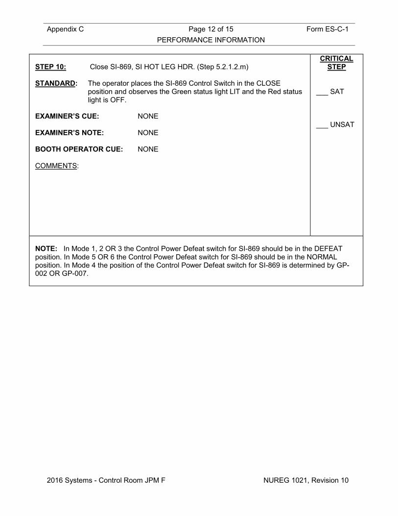
Appendix C Page 12 of 15 Form ES-C-1 PERFORMANCE INFORMATION
2016 Systems - Control Room JPM F NUREG 1021, Revision 10
STEP 10: Close SI-869, SI HOT LEG HDR. (Step 5.2.1.2.m)
STANDARD: The operator places the SI-869 Control Switch in the CLOSE
position and observes the Green status light LIT and the Red status light is OFF.
EXAMINER’S CUE: NONE EXAMINER’S NOTE: NONE BOOTH OPERATOR CUE: NONE COMMENTS:
CRITICAL STEP
___ SAT ___ UNSAT
NOTE: In Mode 1, 2 OR 3 the Control Power Defeat switch for SI-869 should be in the DEFEAT position. In Mode 5 OR 6 the Control Power Defeat switch for SI-869 should be in the NORMAL position. In Mode 4 the position of the Control Power Defeat switch for SI-869 is determined by GP-002 OR GP-007.

Appendix C Page 13 of 15 Form ES-C-1 PERFORMANCE INFORMATION
2016 Systems - Control Room JPM F NUREG 1021, Revision 10
STEP 11: ENSURE the Control Power Defeat switch for SI-869 in the position
determined by plant status. (Step 5.2.1.2.n)
STANDARD: The operator reads the Note, and proceeds. The operator places the SI-869 NORMAL/DEFEAT key switch in
the DEFEAT position and observes the Amber status light is OFF. EXAMINER’S CUE: NA EXAMINER’S NOTE: Key switch for SI-869 is located in the rear of the
RTGB on the ECCS VALVES CONTROL POWER DEFEAT PANEL.
BOOTH OPERATOR CUE: NONE COMMENTS:
CRITICAL
STEP ___ SAT ___ UNSAT
Terminating Cue: Evaluation on this JPM is complete. STOP TIME:

Appendix C Page 14 of 15 Form ES-C-1 VERIFICATION OF COMPLETION
2016 Systems - Control Room JPM F NUREG 1021, Revision 10
Job Performance Measure No.: 2016 Systems - Control Room JPM F
Examinee’s Name:
Date Performed:
Facility Evaluator:
Number of Attempts:
Time to Complete:
Question Documentation:
Result: SAT UNSAT Examiner’s Signature: Date:

Appendix C Form ES-C-1 JPM CUE SHEET
NUREG 1021, Revision 10
INITIAL CONDITIONS: • The plant is at 100% power.
• SI ACCUM C HI/LO LVL (APP-002-E4) alarm has been received and actions have been reviewed by the RO.
• You are the Licensed Dedicated Operator referred to in OP-202.
INITIATING CUE: The CRS has briefed and directed you to fill SI Accumulator “C” to
reset the low level alarm IAW OP-202, Section 5.2.1.

Appendix C Job Performance Measure Form ES-C-1 Worksheet
2016 Systems - Control Room JPM G (Rev_011116) NUREG 1021, Revision 10
SIM JPM G Developed By: ______________________________ Date: ___________ Instructor/Developer Concurred By: ______________________________ Date: ___________ Line Superintendent/Supervisor SRO Approved By: ______________________________ Date: ___________ Superintendent/Supervisor Training

Appendix C Page 2 of 10 Form ES-C-1 Job Performance Measure Worksheet
2016 Systems - Control Room JPM G NUREG 1021, Revision 10
Facility: HB Robinson Task No.: Task Title: Remove Source Range Channel N-
31 From Service JPM No.: 2016 Systems - Control
Room JPM G K/A Reference: 015 A4.03 (3.8/3.9) Examinee: NRC Examiner:
Facility Evaluator: Date:
Method of testing:
Simulated Performance: Actual Performance: X Classroom Simulator X Plant
READ TO THE EXAMINEE
I will explain the initial conditions, which steps to simulate or discuss, and provide initiating cues. When you complete the task successfully, the objective for this Job Performance Measure will be satisfied.
Provide Operator with Initial Conditions/Cue (Last Page of this JPM), and Handout 1. Initial Conditions: • A plant startup is in progress in accordance with GP-003, Normal Plant
Startup From Hot Shutdown to Critical. • SR Channel N-31 has just failed low. Initiating Cue: • The CRS has directed you to remove SR Channel N-31 from service
IAW OWP-011, Nuclear Instrumentation. • The latest Revision of OWP-011 has been verified to be Rev 24,
and the associated Work Request is 16-02. Task Standard: The operator will remove SR Channel N-31 from service IAW NI-5 of
OWP-011. Required Materials: None General References: OWP-011 (Nuclear Instrumentation), Rev 24 GP-003, Normal Plant Startup From Hot Shutdown to Critical, Rev 105
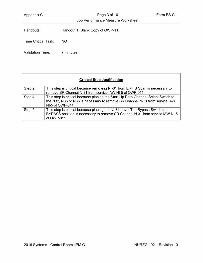
Appendix C Page 3 of 10 Form ES-C-1 Job Performance Measure Worksheet
2016 Systems - Control Room JPM G NUREG 1021, Revision 10
Handouts: Handout 1: Blank Copy of OWP-11. Time Critical Task: NO Validation Time: 7 minutes
Critical Step Justification
Step 2 This step is critical because removing NI-31 from ERFIS Scan is necessary to
remove SR Channel N-31 from service IAW NI-5 of OWP-011. Step 4 This step is critical because placing the Start Up Rate Channel Select Switch to
the N32, N35 or N36 is necessary to remove SR Channel N-31 from service IAW NI-5 of OWP-011.
Step 5 This step is critical because placing the NI-31 Level Trip Bypass Switch to the BYPASS position is necessary to remove SR Channel N-31 from service IAW NI-5 of OWP-011.

Appendix C Page 4 of 10 Form ES-C-1 Job Performance Measure Worksheet
2016 Systems - Control Room JPM G NUREG 1021, Revision 10
SIMULATOR OPERATIONAL GUIDELINES 1. Reset simulator to IC-8, (47.25 hours tripped, Critical at 48 hours). 2. Place in RUN and allow time to stabilize. 3. Perform the following:
• Rod Bank Select Switch to SBB • Withdrawal SBB rods to 225 Steps • Rod Bank Select Switch to M • Withdrawal CBA rods to 22 Steps • Place Audio Count Rate Selector in the N31 position • Place the Startup Rate Channel Select Switch in the N31 position
4. Insert Malfunction NIS01A, Final: 1 (SR N-31 fails LOW) 5. Acknowledge alarms and stabilize the plant. 6. Freeze the Simulator. OR 1. Reset Simulator to Temporary Snap IC-606 (August, 2015). 2. Place Simulator in Run when Operator assumes the watch.

Appendix C Page 5 of 10 Form ES-C-1 PERFORMANCE INFORMATION
2016 Systems - Control Room JPM G NUREG 1021, Revision 10
(Critical Steps are identified as such in right-hand column) Provide Operator with Initial Conditions/Cue (Last Page of this JPM), and Handout 1. START TIME:
STEP 1: Obtain and review the procedure. (OWP-011, NI-5, Steps 1-7).
STANDARD: The operator reviews Handout 1 and identifies that NI-5 must be
addressed. The operator verifies that Revision 24 is the latest revision (Initial
Cue), and prints their name, signs and dates Step 1. Operator reviews Steps 2-7. EXAMINER’S CUE: NONE EXAMINER’S NOTE: The operator may use Green Dots to flag the
expected annunciators. BOOTH OPERATOR CUE: NONE COMMENTS:
___ SAT ___ UNSAT

Appendix C Page 6 of 10 Form ES-C-1 PERFORMANCE INFORMATION
2016 Systems - Control Room JPM G NUREG 1021, Revision 10
STEP 2: Complete Step 8: REMOVE NI-31 from ERFIS SCAN: NIN0031A. (NI-5 Valve, Breaker, Switch Lineup).
STANDARD: The operator selects F3 on ERFIS (Master Menu) The operator selects ADMIN (Administrative Functions Menu) The operator selects DR (Del/Res Point From/To Scan or Alarm) The operator depresses the DELETE SCAN pushbutton The operator enters Point I.D. NIN0031A EXAMINER’S CUE: NONE EXAMINER’S NOTE: This can be checked on ERFIS as follows: Select F3 (Master Menu) Select REAL (Real Time Data Menu) Select DBO (Point Information/Value Display) Enter NNI0031A Observe QUALITY to be DEL BOOTH OPERATOR CUE: NONE COMMENTS:
CRITICAL
STEP ___ SAT ___ UNSAT
STEP 3: Complete Step 8: AUDIO COUNT RATE CHANNEL – CHANNEL SELECTOR Switch (NI-5 Valve, Breaker, Switch Lineup).
STANDARD: The operator pulls and rotates the Audio Count Rate Channel
Selector Switch counter-clockwise to the N32 position, and initials the Selected to SR 32 block on the NI-5 Valve, Breaker, Switch Lineup.
EXAMINER’S CUE: NONE EXAMINER’S NOTE: This switch is on the Audio Count Rate Drawer BOOTH OPERATOR CUE: NONE COMMENTS:
___ SAT ___ UNSAT
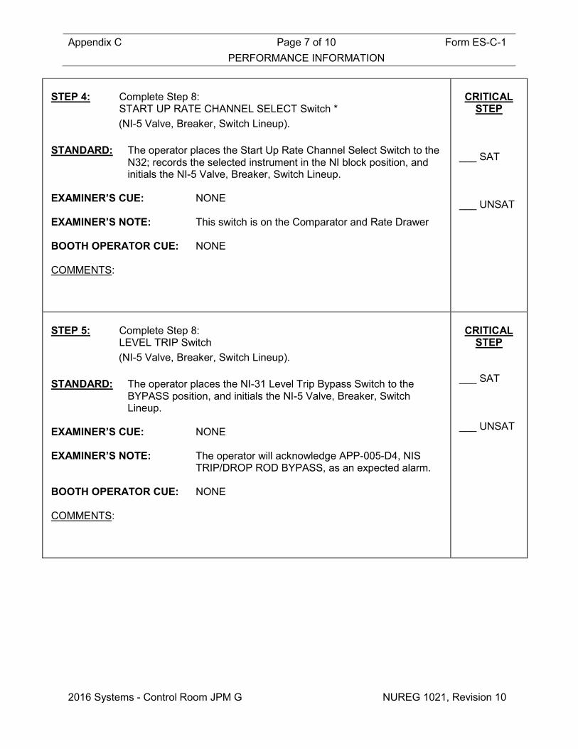
Appendix C Page 7 of 10 Form ES-C-1 PERFORMANCE INFORMATION
2016 Systems - Control Room JPM G NUREG 1021, Revision 10
STEP 4: Complete Step 8: START UP RATE CHANNEL SELECT Switch * (NI-5 Valve, Breaker, Switch Lineup).
STANDARD: The operator places the Start Up Rate Channel Select Switch to the
N32; records the selected instrument in the NI block position, and initials the NI-5 Valve, Breaker, Switch Lineup.
EXAMINER’S CUE: NONE EXAMINER’S NOTE: This switch is on the Comparator and Rate Drawer BOOTH OPERATOR CUE: NONE COMMENTS:
CRITICAL
STEP ___ SAT ___ UNSAT
STEP 5: Complete Step 8: LEVEL TRIP Switch (NI-5 Valve, Breaker, Switch Lineup).
STANDARD: The operator places the NI-31 Level Trip Bypass Switch to the
BYPASS position, and initials the NI-5 Valve, Breaker, Switch Lineup.
EXAMINER’S CUE: NONE EXAMINER’S NOTE: The operator will acknowledge APP-005-D4, NIS
TRIP/DROP ROD BYPASS, as an expected alarm. BOOTH OPERATOR CUE: NONE COMMENTS:
CRITICAL
STEP ___ SAT ___ UNSAT

Appendix C Page 8 of 10 Form ES-C-1 PERFORMANCE INFORMATION
2016 Systems - Control Room JPM G NUREG 1021, Revision 10
STEP 6: Complete Step 8: NIS TRIP BYPASS NI-31 Status Light (NI-5 Valve, Breaker, Switch Lineup).
STANDARD: The operator observes the NI-31 LEVEL TRIP BYPASS status light
is LIT and initials the NI-5 Valve, Breaker, Switch Lineup. EXAMINER’S CUE: NONE EXAMINER’S NOTE: NONE BOOTH OPERATOR CUE: NONE COMMENTS:
___ SAT ___ UNSAT
STEP 7: Complete Step 8: HIGH FLUX AT SHUTDOWN Switch (NI-5 Valve, Breaker, Switch Lineup).
STANDARD: The operator places the NI-High Flux At Shutdown Switch to the
BLOCK position, and initials the NI-5 Valve, Breaker, Switch Lineup. The operator signs and dates Step 8 of NI-5. EXAMINER’S CUE: NONE EXAMINER’S NOTE: The operator will acknowledge APP-005-B1, HI
FLUX AT SHUTDOWN ALARM BLOCK, as an expected alarm.
BOOTH OPERATOR CUE: NONE COMMENTS:
___ SAT ___ UNSAT
Terminating Cue: Evaluation on this JPM is complete. STOP TIME:

Appendix C Page 9 of 10 Form ES-C-1 VERIFICATION OF COMPLETION
2016 Systems - Control Room JPM G NUREG 1021, Revision 10
Job Performance Measure No.: 2016 Systems - Control Room JPM G
Examinee’s Name:
Date Performed:
Facility Evaluator:
Number of Attempts:
Time to Complete:
Question Documentation:
Result: SAT UNSAT Examiner’s Signature: Date:

Appendix C Form ES-C-1 JPM CUE SHEET
NUREG 1021, Revision 10
INITIAL CONDITIONS: • A plant startup is in progress in accordance with GP-003,
Normal Plant Startup From Hot Shutdown to Critical. • SR Channel N-31 has just failed low. INITIATING CUE: • The CRS has directed you to remove SR Channel N-31 from
service IAW OWP-011, Nuclear Instrumentation. • The latest Revision of OWP-011 has been verified to be Rev
24, and the associated Work Request is 16-02.

Appendix C Job Performance Measure Form ES-C-1 Worksheet
2016 Systems - Control Room JPM H (Rev_011116) NUREG 1021, Revision 10
SIM JPM H Developed By: ______________________________ Date: ___________ Instructor/Developer Concurred By: ______________________________ Date: ___________ Line Superintendent/Supervisor SRO Approved By: ______________________________ Date: ___________ Superintendent/Supervisor Training
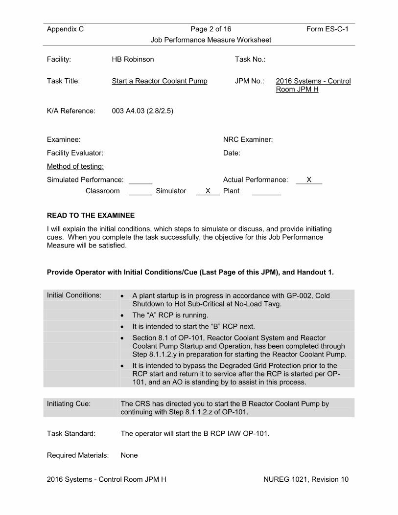
Appendix C Page 2 of 16 Form ES-C-1 Job Performance Measure Worksheet
2016 Systems - Control Room JPM H NUREG 1021, Revision 10
Facility: HB Robinson Task No.: Task Title: Start a Reactor Coolant Pump JPM No.: 2016 Systems - Control
Room JPM H K/A Reference: 003 A4.03 (2.8/2.5) Examinee: NRC Examiner:
Facility Evaluator: Date:
Method of testing:
Simulated Performance: Actual Performance: X Classroom Simulator X Plant
READ TO THE EXAMINEE
I will explain the initial conditions, which steps to simulate or discuss, and provide initiating cues. When you complete the task successfully, the objective for this Job Performance Measure will be satisfied.
Provide Operator with Initial Conditions/Cue (Last Page of this JPM), and Handout 1. Initial Conditions: • A plant startup is in progress in accordance with GP-002, Cold
Shutdown to Hot Sub-Critical at No-Load Tavg. • The “A” RCP is running. • It is intended to start the “B” RCP next. • Section 8.1 of OP-101, Reactor Coolant System and Reactor
Coolant Pump Startup and Operation, has been completed through Step 8.1.1.2.y in preparation for starting the Reactor Coolant Pump.
• It is intended to bypass the Degraded Grid Protection prior to the RCP start and return it to service after the RCP is started per OP-101, and an AO is standing by to assist in this process.
Initiating Cue: The CRS has directed you to start the B Reactor Coolant Pump by
continuing with Step 8.1.1.2.z of OP-101. Task Standard: The operator will start the B RCP IAW OP-101. Required Materials: None

Appendix C Page 3 of 16 Form ES-C-1 Job Performance Measure Worksheet
2016 Systems - Control Room JPM H NUREG 1021, Revision 10
General References: OP-101 (Reactor Coolant System and Reactor Coolant Pump Startup and Operation), Rev 74
AD-OP-ALL-1000 (Conduct of Operations) Rev 4 AOP-018 (Reactor Coolant Pump Abnormal Conditions), Rev 31 APP-001 (Miscellaneous NSSS), Rev 60 Technical Specification LCO 3.3.5 (Loss of Power (LOP) Diesel
Generator (DG) Start Instrumentation), Amendment 176 Handouts: Handout 1: Section 8.1 of OP-101 marked up through Step 8.1.1.2.y for
this JPM. Time Critical Task: NO Validation Time: 10 minutes NOTE: This JPM should be pre-briefed in the Briefing Room.
Critical Step Justification
Step 2 This step is critical because contacting the AO and directing the performance of
Step 8.1.1.2.aa.1&3 is necessary to start the B RCP IAW OP-101. Step 3 This step is critical because placing the Bearing Lift Pump in the START position,
and observing that the LIFT PRESSURE status light is LIT is necessary to start the B RCP IAW OP-101.
Step 6 This step is critical because after 2 minutes with the Bearing Oil Lift Pump running, placing the B RCP Control Switch to the START position is necessary to start the B RCP IAW OP-101.
Step 8 This step is critical because contacting the AO and directing the performance of Step 8.1.1.2.gg.1-6 is necessary to start the B RCP IAW OP-101.
Step 10 This step is critical because contacting the AO and directing the performance of Step 8.1.1.2.ii.1-6. is necessary to start the B RCP IAW OP-101.
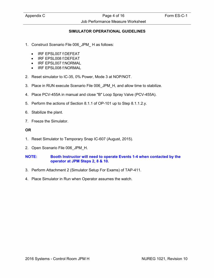
Appendix C Page 4 of 16 Form ES-C-1 Job Performance Measure Worksheet
2016 Systems - Control Room JPM H NUREG 1021, Revision 10
SIMULATOR OPERATIONAL GUIDELINES 1. Construct Scenario File 006_JPM_ H as follows:
• IRF EPSL007 f:DEFEAT • IRF EPSL008 f:DEFEAT • IRF EPSL007 f:NORMAL • IRF EPSL008 f:NORMAL
2. Reset simulator to IC-35, 0% Power, Mode 3 at NOP/NOT. 3. Place in RUN execute Scenario File 006_JPM_H, and allow time to stabilize. 4. Place PCV-455A in manual and close "B" Loop Spray Valve (PCV-455A). 5. Perform the actions of Section 8.1.1 of OP-101 up to Step 8.1.1.2.y. 6. Stabilize the plant. 7. Freeze the Simulator. OR 1. Reset Simulator to Temporary Snap IC-607 (August, 2015). 2. Open Scenario File 006_JPM_H. NOTE: Booth Instructor will need to operate Events 1-4 when contacted by the
operator at JPM Steps 2, 8 & 10. 3. Perform Attachment 2 (Simulator Setup For Exams) of TAP-411. 4. Place Simulator in Run when Operator assumes the watch.
Appendix C Page 5 of 16 Form ES-C-1 PERFORMANCE INFORMATION
2016 Systems - Control Room JPM H NUREG 1021, Revision 10
(Critical Steps are identified as such in right-hand column) Provide Operator with Initial Conditions/Cue (Last Page of this JPM), and Handout 1. START TIME:
NOTES
ITS LCO 3.3.5 allows bypassing Degraded Grid Protection when the Unit is NOT in Mode 1. Conservative operating principles have determined that bypassing the Degraded Grid Protection will only be permitted when the Unit is NOT in Mode 1 OR Mode 2. (NCR 151422) Degraded Grid Voltage Protection is limited to one hour in the DEFEAT position before it shall be returned to NORMAL. (NCR 151422) STEP 1: IF required, THEN ENTER LCO 3.3.5 Action Statement due to
bypassing Degraded Grid Protection, AND RECORD time. (Step 8.1.1.2.z).
STANDARD: The operator reads the Note, and proceeds. The operator records the time in the block provided. The operator informs the CRS that LCO 3.3.5 may need to be
entered. EXAMINER’S CUE: As the CRS, acknowledge report. EXAMINER’S NOTE: NONE BOOTH OPERATOR CUE: NONE COMMENTS:
___ SAT ___ UNSAT

Appendix C Page 6 of 16 Form ES-C-1 PERFORMANCE INFORMATION
2016 Systems - Control Room JPM H NUREG 1021, Revision 10
STEP 2: IF degraded grid protection is in service, THEN DEFEAT the
degraded grid voltage protection as follows: • On the front of Bus E-1, Cubicle 18A, INSTALL key in the
DEGRADED GRID VOLTAGE keylock switch AND PLACE in the DEFEAT position.
• CHECK annunciator APP-010-F5, DEGRADED GRID E-1 PROT BYPD, is ILLUMINATED.
• On the front of Bus E-2, Cubicle 28A, INSTALL key in the DEGRADED GRID VOLTAGE keylock switch AND PLACE in the DEFEAT position.
• CHECK annunciator APP-010-F6, DEGRADED GRID E-2 PROT BYPD, is ILLUMINATED. (Step 8.1.1.2.aa).
STANDARD: The operator contacts AO and directs performance of Step 8.1.1.2.aa.1&3.
The operator observes APP-010-F5, DEGRADED GRID E-1 PROT
BYPD, is LIT and is an expected alarm. The operator observes APP-010-F6, DEGRADED GRID E-2 PROT
BYPD, is LIT and is an expected alarm. EXAMINER’S CUE: NONE EXAMINER’S NOTE: NONE BOOTH OPERATOR CUE: When directed, defeat Degraded Grid Protection
on Bus E-1 RFI EPSL007, and report back as AO that Steps 8.1.1.2.aa.1 has been completed
When directed, defeat Degraded Grid Protection
on Bus E-2 RFI EPSL008, and report back as AO that Steps 8.1.1.2.aa.3 has been completed
COMMENTS:
CRITICAL STEP
___ SAT ___ UNSAT
NOTE: Several starts / stops of the Bearing Oil Lift Pump may be required to prime the pump in a Motor where the Upper Reservoir has been drained and refilled.

Appendix C Page 7 of 16 Form ES-C-1 PERFORMANCE INFORMATION
2016 Systems - Control Room JPM H NUREG 1021, Revision 10
STEP 3: START the BRG LIFT PUMP AND CHECK the LIFT PRESSURE
light ILLUMINATES. (Step 8.1.1.2.bb).
STANDARD: The operator reads the Note, and proceeds. The operator places the Bearing Lift Pump “B” Control Switch in the
START position, and observes the Red status light is LIT and the Green status light is OFF.
The operator observes that that the LIFT PRESSURE status light is
LIT. EXAMINER’S CUE: If the operator addresses the CRS/SM about AOP-
018 because of APP-001-E2, as the SM indicate that the performance of the procedure can be deferred.
EXAMINER’S NOTE: APP-001-E2, RCP #1 SEAL LEAKOFF LO FLOW,
alarms when the Bearing Oil Lift Pump is started. This is because the pump start causes the “B” RCP shaft to be lifted affecting the #1 Seal on the “B” RCP, which will affect the #1 Seal Leakoff flows on the other RCPs.
The operator may address the APP, and may
address AOP-018, Reactor Coolant Pump Abnormal Conditions. If so, a NOTE on the Entry Conditions to AOP-018 states that “IF RCP#1 Seal Leakoff flow is below 1 gpm due to plant conditions known to affect leakoff flow, the SM may defer procedure entry provided the #1 Seal Leakoff flow remains above 0.8 gpm.”
BOOTH OPERATOR CUE: NONE COMMENTS:
CRITICAL
STEP ___ SAT ___ UNSAT

Appendix C Page 8 of 16 Form ES-C-1 PERFORMANCE INFORMATION
2016 Systems - Control Room JPM H NUREG 1021, Revision 10
STEP 4: IF RCP Oil Reservoir level annunciator is NOT EXTINGUISHED,
THEN REFER to the appropriate Annunciator Procedure. (Step 8.1.1.2.cc).
STANDARD: The operator observes that APP-001-E8, RCP B OIL RESERV HI/LO LVL, is EXTINGUISHED.
EXAMINER’S CUE: NONE EXAMINER’S NOTE: NONE BOOTH OPERATOR CUE: NONE COMMENTS:
___ SAT ___ UNSAT
STEP 5: NOTIFY RC that RCP’s are to be started AND to monitor for
changing radiological conditions. (Step 8.1.1.2.dd).
STANDARD: The operator contacts RC and makes notification. EXAMINER’S CUE: As RC Supervisor, Acknowledge EXAMINER’S NOTE: NONE BOOTH OPERATOR CUE: NONE COMMENTS:
___ SAT ___ UNSAT
CAUTION: Only one Reactor Coolant Pump is to be started at a time.
Appendix C Page 9 of 16 Form ES-C-1 PERFORMANCE INFORMATION
2016 Systems - Control Room JPM H NUREG 1021, Revision 10
STEP 6: WHEN the Brg Lift Pump has operated for a minimum of 2 minutes,
THEN START the Reactor Coolant Pump. (Step 8.1.1.2.ee).
STANDARD: The operator reads the Caution, and proceeds. The operator will make a plant announcement prior to starting the
RCP. After 2 minutes with the Bearing Oil Lift Pump running, the operator
places the B RCP Control Switch to the START position, and observes the Red status light is LIT and the Green status light is OFF.
The operator will observe FI-424 at 118%. (Not Critical) The operator will observe FI-425 at 118%. (Not Critical) The operator will observe FI-426 at 117%. (Not Critical) The operator will observe “B” RCP #1 Seal Leakoff on FR-154B to
be 1.24 gpm. (Not Critical) The operator will observe RCS pressure on PR-444 to be ≈360 psig.
(Not Critical) EXAMINER’S CUE: NONE EXAMINER’S NOTE: NONE BOOTH OPERATOR CUE: NONE COMMENTS:
CRITICAL
STEP ___ SAT ___ UNSAT
Appendix C Page 10 of 16 Form ES-C-1 PERFORMANCE INFORMATION
2016 Systems - Control Room JPM H NUREG 1021, Revision 10
STEP 7: WHEN a minimum of 50 seconds has elapsed since the Reactor
Coolant Pump was started, THEN STOP the BRG LIFT PUMP. (Step 8.1.1.2.ff).
STANDARD: After a minimum of 50 seconds with the B RCP Running, the operator places the Bearing Oil Lift Pump Control Switch to the STOP position, and observes the Green status light is LIT and the Red status light is OFF.
The operator observes that that the LIFT PRESSURE status light is OFF.
EXAMINER’S CUE: NONE EXAMINER’S NOTE: NONE BOOTH OPERATOR CUE: NONE COMMENTS:
___ SAT ___ UNSAT
CAUTION: Do NOT Restore the Degraded Grid Voltage Protection to NORMAL until the Amber indicating light is Extinguished. NOTE: The Degraded Grid Voltage keylock keys can NOT be removed from switches unless positioned to NORMAL.

Appendix C Page 11 of 16 Form ES-C-1 PERFORMANCE INFORMATION
2016 Systems - Control Room JPM H NUREG 1021, Revision 10
STEP 8: IF E-1 Degraded Grid Voltage Protection is to be returned to
NORMAL, THEN RESTORE as follows: • Momentarily DEPRESS the amber E-1 DEGRADED GRID TRIP
SIGNAL light cover AND CHECK the light ILLUMINATES. • CHECK the amber E-1 DEGRADED GRID TRIP SIGNAL light is
EXTINGUISHED. • PLACE E-1 DEGRADED GRID VOLTAGE key switch to
NORMAL. • REMOVE key. • IF all three RCPs have been placed in service, THEN NOTIFY
I&C to perform Attachment 10.3, E-1 Defeat Switch Contact Position Verification.
• ENSURE Relay 27 contacts are RESET by performing the following:
o DEPRESS the TARGET RESET pushbutton for Relay 27/DVA-1 AND CHECK that the target flag indicates black.
o DEPRESS the TARGET RESET pushbutton for Relay 27/DVB-1 AND CHECK that the target flag indicates black.
o DEPRESS the TARGET RESET pushbutton for Relay 27/DVC-1 AND CHECK that the target flag indicates black.
• CHECK annunciator APP-010-F5, DEGRADED GRID E-1 PROT BYPD, is EXTINGUISHED. (Step 8.1.1.2.gg.1-7).
STANDARD: The operator reads the Caution and Note, and proceeds. The operator contacts AO and directs performance of Step
8.1.1.2.gg.1-6. The operator observes APP-010-F5, DEGRADED GRID E-1 PROT
BYPD, is EXTINGUISHED. EXAMINER’S CUE: If the operator asks the CRS about leaving the
Degraded Grid Voltage Protection in effect until after the “C” RCP is started, direct the operator to continue with the procedure as written.
EXAMINER’S NOTE: NONE BOOTH OPERATOR CUE: When directed, return Degraded Grid Protection
on Bus E-1 to normal RFI EPSL007, and report back as AO that Steps 8.1.1.2.gg.1-6 have been completed
COMMENTS:
CRITICAL STEP
___ SAT ___ UNSAT
Appendix C Page 12 of 16 Form ES-C-1 PERFORMANCE INFORMATION
2016 Systems - Control Room JPM H NUREG 1021, Revision 10
STEP 9: IF an Action Statement has been entered due to bypassing
Degraded Grid Protection, THEN NOTIFY the CRS/SM of exiting the Action Statement AND RECORD time. (Step 8.1.1.2.hh).
STANDARD: The operator records the time in the block provided. EXAMINER’S CUE: NONE EXAMINER’S NOTE: NONE BOOTH OPERATOR CUE: NONE COMMENTS:
___ SAT ___ UNSAT
Appendix C Page 13 of 16 Form ES-C-1 PERFORMANCE INFORMATION
2016 Systems - Control Room JPM H NUREG 1021, Revision 10
STEP 10: IF E-2 Degraded Grid Voltage Protection is to be returned to
NORMAL, THEN RESTORE as follows: • Momentarily DEPRESS the amber E-2 DEGRADED GRID TRIP
SIGNAL light cover AND CHECK the light ILLUMINATES. • CHECK the amber E-2 DEGRADED GRID TRIP SIGNAL light is
EXTINGUISHED. • PLACE E-2 DEGRADED GRID VOLTAGE key switch to
NORMAL. • REMOVE key. • IF all three RCPs have been placed in service, THEN NOTIFY
I&C to perform Attachment 10.4, E-2 Defeat Switch Contact Position Verification.
• ENSURE relay 27 contacts are RESET by performing the following:
o DEPRESS the TARGET RESET pushbutton for relay 27/DVA-2 AND CHECK that the target flag indicates black.
o DEPRESS the TARGET RESET pushbutton for relay 27/DVB-2 AND CHECK that the target flag indicates black.
o DEPRESS the TARGET RESET pushbutton for relay 27/DVC-2 AND CHECK that the target flag indicates black.
• CHECK annunciator APP-010-F6, DEGRADED GRID E-2 PROT BYPD, is EXTINGUISHED. (Step 8.1.1.2.ii).
STANDARD: The operator contacts AO and directs performance of Step 8.1.1.2.ii.1-6.
The operator observes APP-010-F6, DEGRADED GRID E-2 PROT
BYPD, is EXTINGUISHED. EXAMINER’S CUE: If the operator asks the CRS about leaving the
Degraded Grid Voltage Protection in effect until after the “C” RCP is started, direct the operator to continue with the procedure as written.
EXAMINER’S NOTE: NONE BOOTH OPERATOR CUE: When directed, return Degraded Grid Protection
on Bus E-2 to normal RFI EPSL008, and report back as AO that Steps 8.1.1.2.ii.1-6 have been completed
COMMENTS:
CRITICAL
STEP ___ SAT ___ UNSAT

Appendix C Page 14 of 16 Form ES-C-1 PERFORMANCE INFORMATION
2016 Systems - Control Room JPM H NUREG 1021, Revision 10
STEP 11: IF an Action Statement has been entered due to bypassing
Degraded Grid Protection, THEN NOTIFY the CRS/SM of exiting the Action Statement AND RECORD time. (Step 8.1.1.2.jj).
STANDARD: The operator records the time in the block provided. The operator informs the CRS that the LCO 3.3.5 Action Statement
may be able to be exited. EXAMINER’S CUE: NONE EXAMINER’S NOTE: NONE BOOTH OPERATOR CUE: NONE COMMENTS:
___ SAT ___ UNSAT
Terminating Cue: Evaluation on this JPM is complete. STOP TIME:

Appendix C Page 15 of 16 Form ES-C-1 VERIFICATION OF COMPLETION
2016 Systems - Control Room JPM H NUREG 1021, Revision 10
Job Performance Measure No.: 2016 Systems - Control Room JPM H
Examinee’s Name:
Date Performed:
Facility Evaluator:
Number of Attempts:
Time to Complete:
Question Documentation:
Result: SAT UNSAT Examiner’s Signature: Date:

Appendix C Form ES-C-1 JPM CUE SHEET
NUREG 1021, Revision 10
INITIAL CONDITIONS: • A plant startup is in progress in accordance with GP-002, Cold
Shutdown to Hot Sub-Critical at No-Load Tavg. • The “A” RCP is running.
• It is intended to start the “B” RCP next.
• Section 8.1 of OP-101, Reactor Coolant System and Reactor Coolant Pump Startup and Operation, has been completed through Step 8.1.1.2.y in preparation for starting the Reactor Coolant Pump.
• It is intended to bypass the Degraded Grid Protection prior to the RCP start and return it to service after the RCP is started per OP-101, and an AO is standing by to assist in this process.
INITIATING CUE: The CRS has directed you to start the B Reactor Coolant Pump by
continuing with Step 8.1.1.2.z of OP-101.
Appendix C Job Performance Measure Form ES-C-1 Worksheet
2016 Systems – In-Plant JPM I (Rev_011116) NUREG 1021, Revision 10
In-Plant JPM I Developed By: ______________________________ Date: ___________ Instructor/Developer Concurred By: ______________________________ Date: ___________ Line Superintendent/Supervisor SRO Approved By: ______________________________ Date: ___________ Superintendent/Supervisor Training
Appendix C Page 2 of 11 Form ES-C-1 Job Performance Measure Worksheet
2016 Systems – In-Plant JPM I NUREG 1021, Revision 10
Facility: HB Robinson Task No.: Task Title: Locally Establish AFW Flow from
the SDAFW Pump and Control S/G Levels and Pressures
JPM No.: 2016 Systems – In-Plant JPM I
K/A Reference: EPE 055 EA2.01 (3.4/3.7) Examinee: NRC Examiner:
Facility Evaluator: Date:
Method of testing:
Simulated Performance: X Actual Performance: Classroom Simulator Plant X
READ TO THE EXAMINEE
I will explain the initial conditions, which steps to simulate or discuss, and provide initiating cues. When you complete the task successfully, the objective for this Job Performance Measure will be satisfied.
Provide Operator with Initial Conditions/Cue (Last Page of this JPM), and Handout 1. Initial Conditions: • The Plant has experienced a loss of onsite and offsite power. • EOP-ECA-0.0, Loss of All AC Power, has been implemented. • Wide range levels in all three SGs are 55%. • Steam Generator pressures are 1075 psig • The SDAFW Pump has just been started. Initiating Cue: The CRS has directed you to locally perform Attachment 4, Local
Control Of S/G Level And Pressure, of EOP-ECA-0.0. Task Standard: The operator will control AFW flow to the Steam Generators and align
the Nitrogen System to the SG PORVs IAW Attachment 4 of EOP-ECA-0.0.
Required Materials: PPE (Hardhat, Safety Glasses, Hearing Protection, Safety Shoes etc.) General References: EOP-ECA-0.0 (Loss of All AC Power), Rev 4

Appendix C Page 3 of 11 Form ES-C-1 Job Performance Measure Worksheet
2016 Systems – In-Plant JPM I NUREG 1021, Revision 10
OMM-022 (Emergency Operating Procedures User’s Guide), Rev 45 Handouts: Handout 1: Blank copy of Attachment 4 of EOP-ECA-0.0. Time Critical Task: NO Validation Time: 7 minutes
Critical Step Justification
Step 1 This step is critical because throttling the SDAFW Pump Discharge Valves is
necessary to control AFW flow to the Steam Generators IAW Attachment 4 of EOP-ECA-0.0.
Step 3 This step is critical because closing IA-297 is necessary to align the Nitrogen System to the SG PORVs IAW Attachment 4 of EOP-ECA-0.0.
Step 4 This step is critical because opening SDN-13 is necessary to align the Nitrogen System to the SG PORVs IAW Attachment 4 of EOP-ECA-0.0.
Step 5 This step is critical because closing SDN-29 is necessary to align the Nitrogen System to the SG PORVs IAW Attachment 4 of EOP-ECA-0.0.
Step 6 This step is critical because opening SDN-28 is necessary to align the Nitrogen System to the SG PORVs IAW Attachment 4 of EOP-ECA-0.0.
Step 7 This step is critical because opening IA-423 is necessary to align the Nitrogen System to the SG PORVs IAW Attachment 4 of EOP-ECA-0.0.

Appendix C Page 4 of 11 Form ES-C-1 PERFORMANCE INFORMATION
2016 Systems – In-Plant JPM I NUREG 1021, Revision 10
(Critical Steps are identified as such in right-hand column) Provide Operator with Initial Conditions/Cue (Last Page of this JPM), and Handout 1. START TIME:
NOTE
Flashlights AND ANY handtools needed are located with AOP/EOP/DSP Tool Kits. The S/G Wide Range level indicators LI‑607A‑2, LI‑607B‑2, AND LI‑607C‑2 located in the Secondary Control Panel are powered from PP‑50 AND should always be available. These channels are credited in the SBO Coping Analysis. STEP 1: Locally THROTTLE The Steam Driven AFW Pump Discharge
Valve(s) At The Secondary Control Panel Area To Maintain S/G WR Levels Between 60% AND 67%. • AFW‑V2‑14A ‑ S/G A • AFW‑V2‑14B ‑ S/G B • AFW‑V2‑14C ‑ S/G C (Step 1)
STANDARD: The operator reads the Notes, and proceeds. The operator depresses the AFW‑V2‑14A, 14B and 14C de-clutch
lever and rotates handwheel counterclockwise to increase feedwater flow or clockwise to decrease feedwater flow.
AS-FOUND: All three valves are CLOSED (Stems fully inserted) EXAMINER’S CUE: After locating and describing how the three valves
are operated, indicate that each valve has been De-Clutched and the handwheel rotated as needed to adjust feedwater flow
When appropriate, indicate that each SG WR level is
64% and stable If the operator elects to OPEN the motor breakers for
these valves, indicate that another operator will perform this action
EXAMINER’S NOTE: The operator may request that a second operator
observe SG WR levels while the remainder of the Attachment is completed
COMMENTS:
CRITICAL STEP
___ SAT ___ UNSAT

Appendix C Page 5 of 11 Form ES-C-1 PERFORMANCE INFORMATION
2016 Systems – In-Plant JPM I NUREG 1021, Revision 10
STEP 2: OBSERVE NOTE Prior To Step 10 AND GO TO Step 10
(Step 2) STANDARD: The operator proceeds to Step 10. AS-FOUND: NA EXAMINER’S CUE: NONE EXAMINER’S NOTE: NONE COMMENTS:
___ SAT ___ UNSAT
NOTE IA‑297 is located at the southeast corner of the Pipe Jungle at an elevation between the feed AND steam lines. STEP 3: CLOSE IA‑297, HDR STOP TO PORV STATION & MSIVS (Step 10) STANDARD: The operator reads the Note, and proceeds. The operator rotates the IA-297 handwheel in the clockwise
direction. AS-FOUND: OPEN (Stem Fully Withdrawn) EXAMINER’S CUE: The IA-297 handwheel will no longer turn in the
clockwise direction and the stem is inserted EXAMINER’S NOTE: Located at the SE corner of Pipe Jungle between the
Feed & Steam lines elevation IA-297 is located in the overhead under a catwalk
and the operator must climb an installed ladder, or proceed up the stairs to the top floor of the Turbine Building. However, the valve can be seen from below or above, and discussion of operation can take place from one of these two locations
COMMENTS:
CRITICAL STEP
___ SAT ___ UNSAT

Appendix C Page 6 of 11 Form ES-C-1 PERFORMANCE INFORMATION
2016 Systems – In-Plant JPM I NUREG 1021, Revision 10
NOTE: SDN‑13 is located at the Steam Dump Nitrogen Accumulator. STEP 4: OPEN SDN‑13, NITROGEN BACK UP SUPPLY
(Step 11) STANDARD: The operator reads the Note, and proceeds. The operator rotates the SDN-13 handwheel in the counter-
clockwise direction. AS-FOUND: CLOSED (Stem Fully Inserted) EXAMINER’S CUE: The SDN-13 handwheel will no longer turn in the
clockwise direction and the stem is inserted. EXAMINER’S NOTE: Located at the Steam Dump Nitrogen Accumulator COMMENTS:
CRITICAL
STEP ___ SAT ___ UNSAT

Appendix C Page 7 of 11 Form ES-C-1 PERFORMANCE INFORMATION
2016 Systems – In-Plant JPM I NUREG 1021, Revision 10
NOTE: SDN‑28 AND SDN‑29 are located at the southeast corner of the Pipe Jungle on the Mezzanine Deck. STEP 5: UNLOCK AND CLOSE SDN‑29, STEAM LINE PORV NITROGEN
B/U TO IA TELL‑TALE DRAIN (Step 12)
STANDARD: The operator reads the Note, and proceeds. The operator unlocks and rotates the SDN-29 handwheel in the
clockwise direction. AS-FOUND: Locked OPEN (Stem Fully Withdrawn) EXAMINER’S CUE: The SDN-29 handwheel will no longer turn in the
clockwise direction and the stem is inserted. EXAMINER’S NOTE: Located at the SE Corner of the Pipe Jungle on the
Mezzanine Deck COMMENTS:
CRITICAL
STEP ___ SAT ___ UNSAT
STEP 6: UNLOCK AND OPEN SDN‑28, NITROGEN BACKUP TO STEAM
LINE PORVS (Step 13)
STANDARD: The operator unlocks and rotates the SDN-28 handwheel in the
counter-clockwise direction. AS-FOUND: Locked CLOSED (Stem Fully Inserted) EXAMINER’S CUE: The SDN-28 handwheel will no longer turn in the
counter-clockwise direction and the stem is withdrawn.
EXAMINER’S NOTE: Located at the SE Corner of the Pipe Jungle on the
Mezzanine Deck COMMENTS:
CRITICAL
STEP ___ SAT ___ UNSAT
Appendix C Page 8 of 11 Form ES-C-1 PERFORMANCE INFORMATION
2016 Systems – In-Plant JPM I NUREG 1021, Revision 10
NOTE: IA‑423 is located at the southeast corner of the Pipe Jungle on the Mezzanine Deck. STEP 7: UNLOCK AND OPEN IA‑423, NITROGEN TO STEAM LINE PORVS
(Step 14) STANDARD: The operator reads the Note, and proceeds. The operator unlocks and rotates the IA-423 handwheel in the
counter-clockwise direction. AS-FOUND: Locked CLOSED (Stem Fully Inserted) EXAMINER’S CUE: The IA-423 handwheel will no longer turn in the
counter-clockwise direction and the stem is withdrawn.
EXAMINER’S NOTE: Located at the SE Corner of the Pipe Jungle on the
Mezzanine Deck COMMENTS:
CRITICAL
STEP ___ SAT ___ UNSAT
STEP 8: NOTIFY The Control Room Of The Following:
• S/G level is under control locally • The S/G Steam Line PORVs have N2 supplied for motive air
(Step 15/15.a and b) STANDARD: The operator contacts the Control Room and makes the
notifications. AS-FOUND: NA EXAMINER’S CUE: As the CRS, acknowledge EXAMINER’S NOTE: NONE COMMENTS:
___ SAT ___ UNSAT
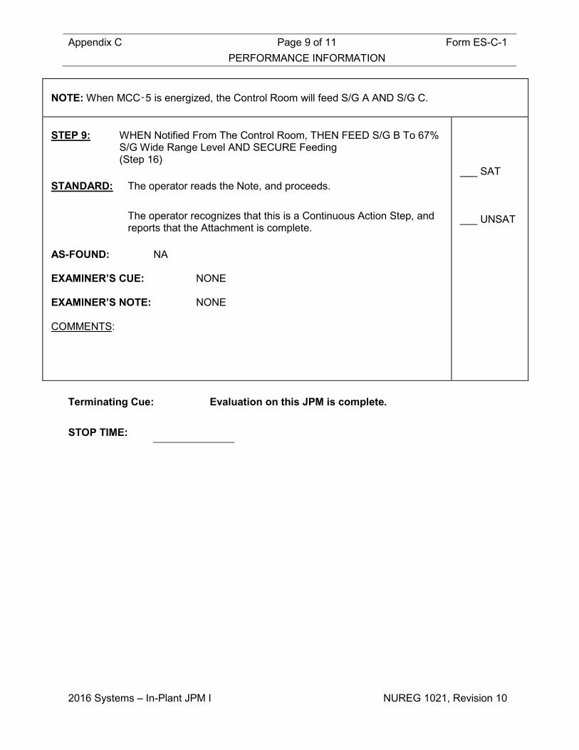
Appendix C Page 9 of 11 Form ES-C-1 PERFORMANCE INFORMATION
2016 Systems – In-Plant JPM I NUREG 1021, Revision 10
NOTE: When MCC‑5 is energized, the Control Room will feed S/G A AND S/G C. STEP 9: WHEN Notified From The Control Room, THEN FEED S/G B To 67%
S/G Wide Range Level AND SECURE Feeding (Step 16)
STANDARD: The operator reads the Note, and proceeds. The operator recognizes that this is a Continuous Action Step, and
reports that the Attachment is complete. AS-FOUND: NA EXAMINER’S CUE: NONE EXAMINER’S NOTE: NONE COMMENTS:
___ SAT ___ UNSAT
Terminating Cue: Evaluation on this JPM is complete. STOP TIME:

Appendix C Page 10 of 11 Form ES-C-1 VERIFICATION OF COMPLETION
2016 Systems – In-Plant JPM I NUREG 1021, Revision 10
Job Performance Measure No.: 2016 Systems – In-Plant JPM I
Examinee’s Name:
Date Performed:
Facility Evaluator:
Number of Attempts:
Time to Complete:
Question Documentation:
Result: SAT UNSAT Examiner’s Signature: Date:

Appendix C Form ES-C-1 JPM CUE SHEET
NUREG 1021, Revision 10
INITIAL CONDITIONS: • The Plant has experienced a loss of onsite and offsite power.
• EOP-ECA-0.0, Loss of All AC Power, has been implemented.
• Wide range levels in all three SGs are 55%.
• Steam Generator pressures are 1075 psig
• The SDAFW Pump has just been started. INITIATING CUE: The CRS has directed you to locally perform Attachment 4,
Local Control Of S/G Level And Pressure, of EOP-ECA-0.0.
NOTE: No plant equipment should be operated during the performance of this JPM. All actions must be SIMULATED.

Appendix C Job Performance Measure Form ES-C-1 Worksheet
2016 Systems – In-Plant JPM J (Rev_011116) NUREG 1021, Revision 10
In-Plant JPM J Developed By: ______________________________ Date: ___________ Instructor/Developer Concurred By: ______________________________ Date: ___________ Line Superintendent/Supervisor SRO Approved By: ______________________________ Date: ___________ Superintendent/Supervisor Training

Appendix C Page 2 of 10 Form ES-C-1 Job Performance Measure Worksheet
2016 Systems – In-Plant JPM J NUREG 1021, Revision 10
Facility: HB Robinson Task No.: Task Title: Respond to a Loss of Instrument Air JPM No.: 2016 Systems – In-
Plant JPM J K/A Reference: 065 AA1.04 (3.5.3.4) Examinee: NRC Examiner:
Facility Evaluator: Date:
Method of testing:
Simulated Performance: X Actual Performance: Classroom Simulator Plant X
READ TO THE EXAMINEE
I will explain the initial conditions, which steps to simulate or discuss, and provide initiating cues. When you complete the task successfully, the objective for this Job Performance Measure will be satisfied.
Provide Candidate with Initial Conditions/Cue (Last Page of this JPM), and Handout 1. Initial Conditions: • IA Header Pressure is 75 PSIG and lowering. • AOP-017, Loss Of Instrument Air, has been entered. • The Station Air Compressor is under clearance and disassembled • The Station Air Receiver is depressurized and vented. Initiating Cue: • The CRS has directed you to perform AOP-017 Step 8. • The Outside AO is standing by to assist as needed. Task Standard: The operator will start IA Compressors “A” and “B” and align their
discharge to supply air to the Instrument Air Header in accordance with Step 8 of AOP-017.
Required Materials: PPE (Hardhat, Safety Glasses, Hearing Protection, Safety Shoes etc.) General References: AOP-017 (Loss of Instrument Air), Rev 43 OMM-022 (Emergency Operating Procedures User’s Guide), Rev 45

Appendix C Page 3 of 10 Form ES-C-1 Job Performance Measure Worksheet
2016 Systems – In-Plant JPM J NUREG 1021, Revision 10
Handouts: Handout 1: Blank Copy of AOP-017. Time Critical Task: NO Validation Time: 14 minutes
Critical Step Justification
Step 6 This step is critical because placing the IA Compressor A & B Control Switches in
MANUAL is necessary to start IA Compressors “A” and “B” in accordance with Step 8 of AOP-017.
Step 8 This step is critical because rotating the IA‑3665 handwheel in the counter-clockwise direction is necessary to align the IA Compressors “A” and “B” discharge to supply air to the Instrument Air Header in accordance with Step 8 of AOP-017.

Appendix C Page 4 of 10 Form ES-C-1 PERFORMANCE INFORMATION
2016 Systems – In-Plant JPM J NUREG 1021, Revision 10
(Critical Steps are identified as such in right-hand column) Provide Candidate with Initial Conditions/Cue (Last Page of this JPM), and Handout 1. START TIME:
NOTE
IA‑3821 is located on IA Dryer D. Operator Aid 97‑OP‑35 to supply Station Air to Instrument Air is located in the Aux Bldg hallway on the Station Air Receiver. STEP 1: DISPATCH Operator(s) To Perform The Following:
CHECK Station Air Compressor Available For Service: SA‑1, STATION AIR TO RECEIVER ‑ OPEN AND Station Air Compressor Function Switch ‑ ON (Step 8/8.a)
STANDARD: The operator reads the Notes, and proceeds. The operator recognizes that SA-1 is OOS and proceeds to the
RNO. AS FOUND: SA-1 Red Tagged CLOSED, SAC Function Switch is Red
tagged OFF (Cue as needed) EXAMINER’S CUE: NONE EXAMINER’S NOTE: NONE COMMENTS:
___ SAT ___ UNSAT

Appendix C Page 5 of 10 Form ES-C-1 PERFORMANCE INFORMATION
2016 Systems – In-Plant JPM J NUREG 1021, Revision 10
STEP 2: OPEN SA‑1 AND PLACE the Station Air Compressor Function switch
to ON. IF the Station Air Compressor is still NOT available for service, THEN
GO TO Step 8.d. (Step 8.a RNO)
STANDARD: The operator recognizes that SA-1 cannot be opened nor can the SAC Function Switch be placed to ON, and proceeds to Step 8.d.
AS FOUND: SA-1 Red Tagged CLOSED, SAC Function Switch is Red
tagged OFF (Cue as needed) EXAMINER’S CUE: NONE EXAMINER’S NOTE: NONE COMMENTS:
___ SAT ___ UNSAT
STEP 3: CHECK IA‑18, AIR DRYER "A" & "B" BYPASS ‑ OPEN
(Step 8.d) STANDARD: The operator observes IA-18, and (After Cue) proceeds to the Step
8.d RNO. AS FOUND: IA-18 stem is fully inserted (Cue as needed) EXAMINER’S CUE: NONE EXAMINER’S NOTE: NONE COMMENTS:
___ SAT ___ UNSAT

Appendix C Page 6 of 10 Form ES-C-1 PERFORMANCE INFORMATION
2016 Systems – In-Plant JPM J NUREG 1021, Revision 10
STEP 4: OPEN IA‑18, AIR DRYER "A" & "B" BYPASS.
(Step 8.d RNO) STANDARD: The operator rotates the IA-18 handwheel in the counter-clockwise
direction. AS FOUND: IA-18 stem is fully inserted (Cue as needed) EXAMINER’S CUE: After locating and describing how the valve would be
opened, indicate that the stem is fully withdrawn. EXAMINER’S NOTE: NONE COMMENTS:
___ SAT ___ UNSAT
STEP 5: CHECK the following Compressors ‑ RUNNING
• INST AIR COMP A • INST AIR COMP B
(Step 8.e) STANDARD: The operator observes the IA Compressor A Control Switch. The operator observes the IA Compressor B Control Switch. AS FOUND: Both IA Compressors are stopped, with their local control
switches in AUTO (Cue as needed) EXAMINER’S CUE: NONE EXAMINER’S NOTE: NONE COMMENTS:
___ SAT ___ UNSAT
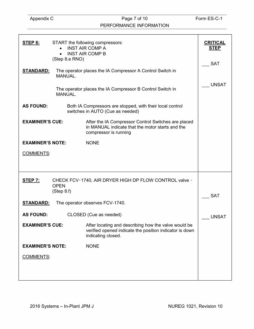
Appendix C Page 7 of 10 Form ES-C-1 PERFORMANCE INFORMATION
2016 Systems – In-Plant JPM J NUREG 1021, Revision 10
STEP 6: START the following compressors:
• INST AIR COMP A • INST AIR COMP B
(Step 8.e RNO) STANDARD: The operator places the IA Compressor A Control Switch in
MANUAL. The operator places the IA Compressor B Control Switch in
MANUAL. AS FOUND: Both IA Compressors are stopped, with their local control
switches in AUTO (Cue as needed) EXAMINER’S CUE: After the IA Compressor Control Switches are placed
in MANUAL indicate that the motor starts and the compressor is running
EXAMINER’S NOTE: NONE COMMENTS:
CRITICAL
STEP ___ SAT ___ UNSAT
STEP 7: CHECK FCV‑1740, AIR DRYER HIGH DP FLOW CONTROL valve ‑
OPEN (Step 8.f)
STANDARD: The operator observes FCV-1740. AS FOUND: CLOSED (Cue as needed) EXAMINER’S CUE: After locating and describing how the valve would be
verified opened indicate the position indicator is down indicating closed.
EXAMINER’S NOTE: NONE COMMENTS:
___ SAT ___ UNSAT
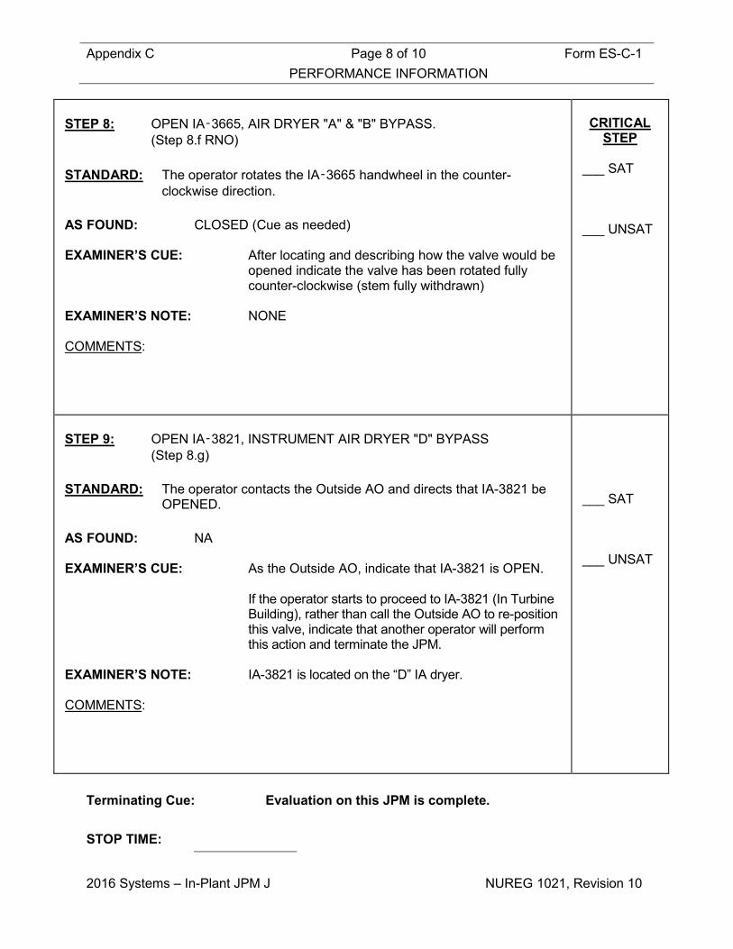
Appendix C Page 8 of 10 Form ES-C-1 PERFORMANCE INFORMATION
2016 Systems – In-Plant JPM J NUREG 1021, Revision 10
STEP 8: OPEN IA‑3665, AIR DRYER "A" & "B" BYPASS.
(Step 8.f RNO) STANDARD: The operator rotates the IA‑3665 handwheel in the counter-
clockwise direction. AS FOUND: CLOSED (Cue as needed) EXAMINER’S CUE: After locating and describing how the valve would be
opened indicate the valve has been rotated fully counter-clockwise (stem fully withdrawn)
EXAMINER’S NOTE: NONE COMMENTS:
CRITICAL
STEP
___ SAT ___ UNSAT
STEP 9: OPEN IA‑3821, INSTRUMENT AIR DRYER "D" BYPASS
(Step 8.g) STANDARD: The operator contacts the Outside AO and directs that IA-3821 be
OPENED. AS FOUND: NA EXAMINER’S CUE: As the Outside AO, indicate that IA-3821 is OPEN. If the operator starts to proceed to IA-3821 (In Turbine
Building), rather than call the Outside AO to re-position this valve, indicate that another operator will perform this action and terminate the JPM.
EXAMINER’S NOTE: IA-3821 is located on the “D” IA dryer. COMMENTS:
___ SAT ___ UNSAT
Terminating Cue: Evaluation on this JPM is complete. STOP TIME:

Appendix C Page 9 of 10 Form ES-C-1 VERIFICATION OF COMPLETION
2016 Systems – In-Plant JPM J NUREG 1021, Revision 10
Job Performance Measure No.: 2016 Systems – In-Plant JPM J
Examinee’s Name:
Date Performed:
Facility Evaluator:
Number of Attempts:
Time to Complete:
Question Documentation:
Result: SAT UNSAT Examiner’s Signature: Date:

Appendix C Form ES-C-1 JPM CUE SHEET
NUREG 1021, Revision 10
INITIAL CONDITIONS: • IA Header Pressure is 75 PSIG and lowering.
• AOP-017, Loss Of Instrument Air, has been entered.
• The Station Air Compressor is under clearance and disassembled
• The Station Air Receiver is depressurized and vented. INITIATING CUE: • The CRS has directed you to perform AOP-017 Step 8.
• The Outside AO is standing by to assist as needed.
NOTE: No plant equipment should be operated during the performance of this JPM. All actions must be SIMULATED.
Appendix C Job Performance Measure Form ES-C-1 Worksheet
2016 Systems – In-Plant JPM K (Rev_011116) NUREG 1021, Revision 10
In-Plant JPM K Developed By: ______________________________ Date: ___________ Instructor/Developer Concurred By: ______________________________ Date: ___________ Line Superintendent/Supervisor SRO Approved By: ______________________________ Date: ___________ Superintendent/Supervisor Training

Appendix C Page 2 of 14 Form ES-C-1 Job Performance Measure Worksheet
2016 Systems – In-Plant JPM K NUREG 1021, Revision 10
Facility: HB Robinson Task No.: Task Title: Loss of North SW Header in the
Auxiliary Building JPM No.: 2016 Systems – In-
Plant JPM K K/A Reference: APE 062 AA2.01 (2.9/3.5) Examinee: NRC Examiner:
Facility Evaluator: Date:
Method of testing:
Simulated Performance: X Actual Performance: Classroom Simulator Plant X
READ TO THE EXAMINEE
I will explain the initial conditions, which steps to simulate or discuss, and provide initiating cues. When you complete the task successfully, the objective for this Job Performance Measure will be satisfied.
Provide Operator with Initial Conditions/Cue (Last Page of this JPM), and Handouts 1-2. Initial Conditions: • The plant is at 100% power. • The North SW header has ruptured inside the Auxiliary Building. • The Control Room has implemented AOP-022 (Loss of Service
Water) for a leak in the North header. Initiating Cue: The CRS has directed you to isolate the leak IAW Attachment 6 of AOP-
022. Task Standard: The operator will isolate the intact SW header from the ruptured header,
isolate the leak, and align cooling water to critical loads IAW Attachment 6 of AOP-022.
Required Materials: PPE (Hardhat, Safety Glasses, Hearing Protection, Safety Shoes etc.) Flashlight Magnifying Glass General References: AOP-022 (Loss of Service Water), Rev 35
Appendix C Page 3 of 14 Form ES-C-1 Job Performance Measure Worksheet
2016 Systems – In-Plant JPM K NUREG 1021, Revision 10
OMM-022 (Emergency Operating Procedures User’s Guide), Rev 45 Plant Drawing G-190199 (Service & Cooling Water Flow Diagram) Rev
72 Figure 9.2.1-1, Flow Diagram Service and Cooling Water, Rev 26 Handouts: Handout 1: Blank Copy of Attachment 6 of AOP-022. Handout 2: Figure 9.2.1-1, Flow Diagram Service and Cooling Water,
with the leak location marked. Time Critical Task: NO Validation Time: 14 minutes
Critical Step Justification
Step 1 This step is critical because closing either SW-18 or SW-19 is necessary to
isolate the ruptured header from intact header. Step 2 This step is critical because closing SW-740 and SW-102 is necessary to isolate
the ruptured header from intact header. Step 4 This step is critical because placing Instrument Air Compressor “B” in OFF is
necessary to prevent damage to the compressor. Step 7 This step is critical because cross-connecting the Booster Pump Suction is
necessary to isolate the leak and align cooling water to critical loads (SW-25 must be closed to prevent reinitiating the leak, SW-26 and SW-27 must be opened to supply cooling water to vital equipment, SW-503 must be closed to prevent reinitiating the leak and SW-200A must be opened to provide emergency make up to the IVSW Tank).
Step 9 This step is critical because Closing SW-53 and Opening SW-83 is necessary to align cooling water to critical loads (EDGs).

Appendix C Page 4 of 14 Form ES-C-1 PERFORMANCE INFORMATION
2016 Systems – In-Plant JPM K NUREG 1021, Revision 10
(Critical Steps are identified as such in right-hand column) Provide Operator with Initial Conditions/Cue (Last Page of this JPM), and Handouts 1-2. START TIME:
CAUTION
Electrically rated boots and gloves must be worn in the Auxiliary Building where flooding is in progress.
NOTE
Dielectric rubber boots and low voltage electrical gloves are available in the AOP/DSP/EOP Equipment storage Locker inside the Auxiliary Building. STEP 1: Close One Of The Following Valves In The Auxiliary Building
Hallway : • SW-18, North & South Supply HDR X-Conn (Chain Operated)
OR • SW-19, North & South Supply HDR X-Conn (Chain Operated)
(Step 1) STANDARD: The operator pulls either the SW-18 or SW-19 chain operator to
rotate valve handwheel in the clockwise direction, and observes the area for water.
AS FOUND: Both Valves Are Open EXAMINER’S CUE: The operator reads the Caution and Note, and
proceeds. After locating and describing how either valve
would be closed then indicate the selected valve has been rotated full clockwise and the pointer indicates “Closed”.
IF asked if any water is observed on the ground in
the AUX BLDG Hallway near the SW Booster Pumps, say YES.
EXAMINER’S NOTE: The valve handwheels face opposite directions.
Ensure operator turns the selected handwheel via the chain in the proper direction.
COMMENTS:
CRITICAL
STEP ___ SAT ___ UNSAT
Appendix C Page 5 of 14 Form ES-C-1 PERFORMANCE INFORMATION
2016 Systems – In-Plant JPM K NUREG 1021, Revision 10
NOTE
SW-102 is located overhead East of CCW Pump B on top of horizontal header supported by adjustable pipe support. STEP 2: Close The Following Valves In The CCW Pump Room:
• SW-740, CCW Heat Exchanger "B" Return • SW-102, HVH-7B Supply
(Step 2) STANDARD: The operator reads the Note, and proceeds. The operator rotates the SW-740 and SW-102 handwheels in the
clockwise direction. AS FOUND: Both Valves Open (SW-740 Pointer Indicates “POS 1” And SW-102
Stem Is Fully Withdrawn). EXAMINER’S CUE: After locating and describing how both valves
would be closed, indicate the valves have been rotated full clockwise, the SW-740 pointer indicates “Closed” and the SW-102 stem is fully inserted.
EXAMINER’S NOTE: SW-102 is located overhead east of CCW Pump
“B” on top of horizontal header supported by adjustable pipe support.
SW-102 is located in the overhead will require a
ladder to manipulate. A ladder is located on the south wall of the CCW Pump Room.
COMMENTS:
CRITICAL
STEP ___ SAT ___ UNSAT

Appendix C Page 6 of 14 Form ES-C-1 PERFORMANCE INFORMATION
2016 Systems – In-Plant JPM K NUREG 1021, Revision 10
STEP 3: Notify Control Room Personnel That Steps 1 And 2 of Attachment 6
Are Complete (Step 3)
STANDARD: The operator contacts the Control Room and reports Steps 1 and 2
of Attachment 6 are complete. AS FOUND: NONE EXAMINER’S CUE: When contacted, as CRS then acknowledge the
report from the operator EXAMINER’S NOTE: NONE COMMENTS:
___ SAT ___ UNSAT
STEP 4: Place Instrument Air Compressor B Control Switch In The OFF
Position (Step 4)
STANDARD: The operator places the Instrument Air Compressor “B” Control
Switch in OFF position AS FOUND: IA Compressor B Control Switch is in AUTO EXAMINER’S CUE: After locating and describing how the “B” IA
compressor would be placed in “OFF” indicate the Control Switch has been rotated to the middle position “OFF”.
EXAMINER’S NOTE: NONE COMMENTS:
CRITICAL
STEP ___ SAT ___ UNSAT
Appendix C Page 7 of 14 Form ES-C-1 PERFORMANCE INFORMATION
2016 Systems – In-Plant JPM K NUREG 1021, Revision 10
CAUTION
Subsequent actions to cross-connect cooling water to plant components should not be performed if the leak will be reinitiated.
NOTE
SW-53, North Supply HDR To "B" TRN Components In Aux Bldg, is located in Auxiliary Building hallway, midway between Instrument Air Dryers A and B, above third cable tray. STEP 5: Check leak location - Downstream of SW-53.
(Step 5) STANDARD: The operator reads the caution and Note, and proceeds. The operator uses the SW flow diagram marked with the leak
location (Handout 2), and observes the area for water and determines leak is NOT Downstream of SW-53; and goes to step 5 RNO which directs the operator to Step 9
AS FOUND: NONE EXAMINER’S CUE: IF asked if any water is observed on the ground in
the AUX BLDG Hallway near the SW Booster Pumps, say YES.
EXAMINER’S NOTE: NONE COMMENTS:
___ SAT ___ UNSAT

Appendix C Page 8 of 14 Form ES-C-1 PERFORMANCE INFORMATION
2016 Systems – In-Plant JPM K NUREG 1021, Revision 10
STEP 6: Check Leak Location – Upstream of SW-25, North HDR Supply To
SW Booster Pump (Step 9)
STANDARD: The operator determines the leak is upstream of SW-25. AS FOUND: NONE EXAMINER’S CUE: IF asked if any water is observed on the ground in
the AUX BLDG Hallway near the SW Booster Pumps, say YES.
EXAMINER’S NOTE: NONE COMMENTS:
___ SAT ___ UNSAT
NOTE
• SW Booster Pump B may be operated as required after the suction path is established from the
South Service Water Header. • Closing SW-503, SW Pump Supply To IVSW Tank, also isolates SW to the Penetration Coolers.

Appendix C Page 9 of 14 Form ES-C-1 PERFORMANCE INFORMATION
2016 Systems – In-Plant JPM K NUREG 1021, Revision 10
STEP 7: Cross-Connect SW Booster Pump Suction Supply As Follows:
a. Close SW-25, North HDR Supply To SW Booster Pumps b. Open SW-26, SW Booster Pump Suction Cross-Connect c. Open SW-27, SW Booster Pump Suction Cross-Connect d. Close SW-503, SW Pump Supply To IVSW Tank e. Open SW-200A, SWBP "A" TO IVSW Tank Supply
(Step 10) STANDARD: The operator reads the Notes, and proceeds. The operator rotates the T-handle locking device counter-clockwise
on SW-25, and rotates the handwheel clockwise. The operator rotates the T-handle locking device counter-clockwise
on SW-26, and rotates the handwheel counter-clockwise. The operator rotates the T-handle locking device counter-clockwise
on SW-27, and rotates the handwheel counter-clockwise. The operator rotates the SW-503 handwheel clockwise. The operator rotates the SW-200A handwheel counter-clockwise. AS FOUND: SW-25 & SW-503, OPEN
SW-26, SW-27 & SW-200A, CLOSED EXAMINER’S CUE: After locating and describing how each valve would
be operated then indicate the selected valve has been rotated full counter-clockwise and the stem is fully withdrawn for the “OPEN” valves and rotated full clockwise with the stem fully inserted for the “CLOSED” valves
SW-26 and 200A is located above the A SW Booster
Pump. SW-503 is located above the vent duct above the B
SW Booster Pump, and requires a ladder. EXAMINER’S NOTE: NONE COMMENTS:
CRITICAL
STEP ___ SAT ___ UNSAT

Appendix C Page 10 of 14 Form ES-C-1 PERFORMANCE INFORMATION
2016 Systems – In-Plant JPM K NUREG 1021, Revision 10
STEP 8: Notify Control Room Personnel That Step 10 Is Complete And SW
Has Been Cross-Connected To Supply SW Booster Pump B (Step 11)
STANDARD: The operator contacts the Control Room and reports SW has been
cross-connected to supply SW Booster Pump “B”. AS FOUND: NONE EXAMINER’S CUE: When contacted, as CRS acknowledge the report
from the operator EXAMINER’S NOTE: NONE COMMENTS:
___ SAT ___ UNSAT
NOTE
• SW-83, Diesel Supply Cross-Connect, is located at the North end of Emergency Diesel Generator
A. • Cross-connecting Service Water to the Emergency Diesel Generators will also cross-connect
Service Water to HVH-6B, HVH-8B, and Instrument Air Compressor B. • A ladder is required for access to SW-53, North Supply HDR To "B" TRN Components In Aux
BLDG.

Appendix C Page 11 of 14 Form ES-C-1 PERFORMANCE INFORMATION
2016 Systems – In-Plant JPM K NUREG 1021, Revision 10
STEP 9: Cross-Connect Service Water Supply To EDGs AS Follows:
a. Close SW-53 b. Open SW-83
(Step 12) STANDARD: The operator reads the Notes, and proceeds. The operator rotates the SW-53 handwheel in the clockwise
direction. The operator rotates the SW-83 handwheel in the counter-clockwise
direction. AS FOUND: SW-53 is OPEN, SW-83 is CLOSED EXAMINER’S CUE: After locating and describing how each valve would
be operated indicate that the SW-53 handwheel has been rotated full clockwise and the stem is fully inserted, and that the SW-83 handwheel has been rotated full counter-clockwise with the stem fully withdrawn.
EXAMINER’S NOTE: SW-53 is located in the overhead will require a
ladder to manipulate. A ladder is located on the south wall of the CCW Pump Room.
There is a label identifying the location of SW-53 on
the vent duct above the walkway between the IA Dryers A and B.
SW-83 is located in the A EDG Vault Room. This
room requires Control Room/WCCS permission to enter the room. The examiner will either need to get permission to enter, or open the door and observe the valve without entering the room (The valve can be seen from the open doorway).
COMMENTS:
CRITICAL
STEP ___ SAT ___ UNSAT

Appendix C Page 12 of 14 Form ES-C-1 PERFORMANCE INFORMATION
2016 Systems – In-Plant JPM K NUREG 1021, Revision 10
STEP 10: Notify Control Room Personnel That SW Has Been Cross-
Connected To Supply The Following Equipment: • EDG B • Instrument Air Compressor B • HVH-6B • HVH-8B
(Step 13) STANDARD: The operator contacts the Control Room and reports that SW has
been cross-connected to supply the above equipment AS FOUND: NONE EXAMINER’S CUE: When contacted, as CRS acknowledge the report
from the operator EXAMINER’S NOTE: NONE COMMENTS:
___ SAT ___ UNSAT
STEP 11: Notify Control Room Personnel That Attachment 6 Is Complete
(Step 14) STANDARD: The operator contacts the control room and reports that Attachment
6 is complete AS FOUND: NONE EXAMINER’S CUE: When contacted, as CRS acknowledge that
Attachment 6 is complete EXAMINER’S NOTE: NONE COMMENTS:
___ SAT ___ UNSAT
Terminating Cue: Evaluation on this JPM is complete. STOP TIME:

Appendix C Page 13 of 14 Form ES-C-1 VERIFICATION OF COMPLETION
2016 Systems – In-Plant JPM K NUREG 1021, Revision 10
Job Performance Measure No.: 2016 Systems – In-Plant JPM K
Examinee’s Name:
Date Performed:
Facility Evaluator:
Number of Attempts:
Time to Complete:
Question Documentation:
Result: SAT UNSAT Examiner’s Signature: Date:
Appendix C Form ES-C-1 JPM CUE SHEET
NUREG 1021, Revision 10
INITIAL CONDITIONS: • The plant is at 100% power.
• The North SW header has ruptured inside the Auxiliary Building.
• The Control Room has implemented AOP-022 (Loss of Service Water) for a leak in the North header.
INITIATING CUE: The CRS has directed you to isolate the leak IAW Attachment 6 of
AOP-022.
NOTE: No plant equipment should be operated during the performance of this JPM. All actions must be SIMULATED.