Embed Size (px)
Citation preview
www.rhydolabz.com SIM900 GSM/GPRS TTL UART Modem - User Manual
W e b r i n g t h e w o r l d t o y o u … … . . Page 1
Document : Datasheet Model # : GSM – 1936
Date : 10-DEC-2011
SIM 900 SIM 900 SIM 900 SIM 900 ----TTL TTL TTL TTL UARTUARTUARTUART
GGGGSSSSM/GM/GM/GM/GPPPPRSRSRSRS MMMMooooddddeeeemmmm
User Manual
Rhydo Technologies (P) Ltd. (An ISO 9001:2008 Certified R&D Company)
Golden Plaza, Chitoor Road,
Cochin – 682018, Kerala State, India
Phone : 0091- 484-2370444, 2371666
Cell : 0091- 99466 70444
Fax : 0091 - 484-2370579
E-mail : [email protected], [email protected]
WebSite : http://www.rhydolabz.com
www.rhydolabz.com SIM900 GSM/GPRS TTL UART Modem - User Manual
W e b r i n g t h e w o r l d t o y o u … … . . Page 2
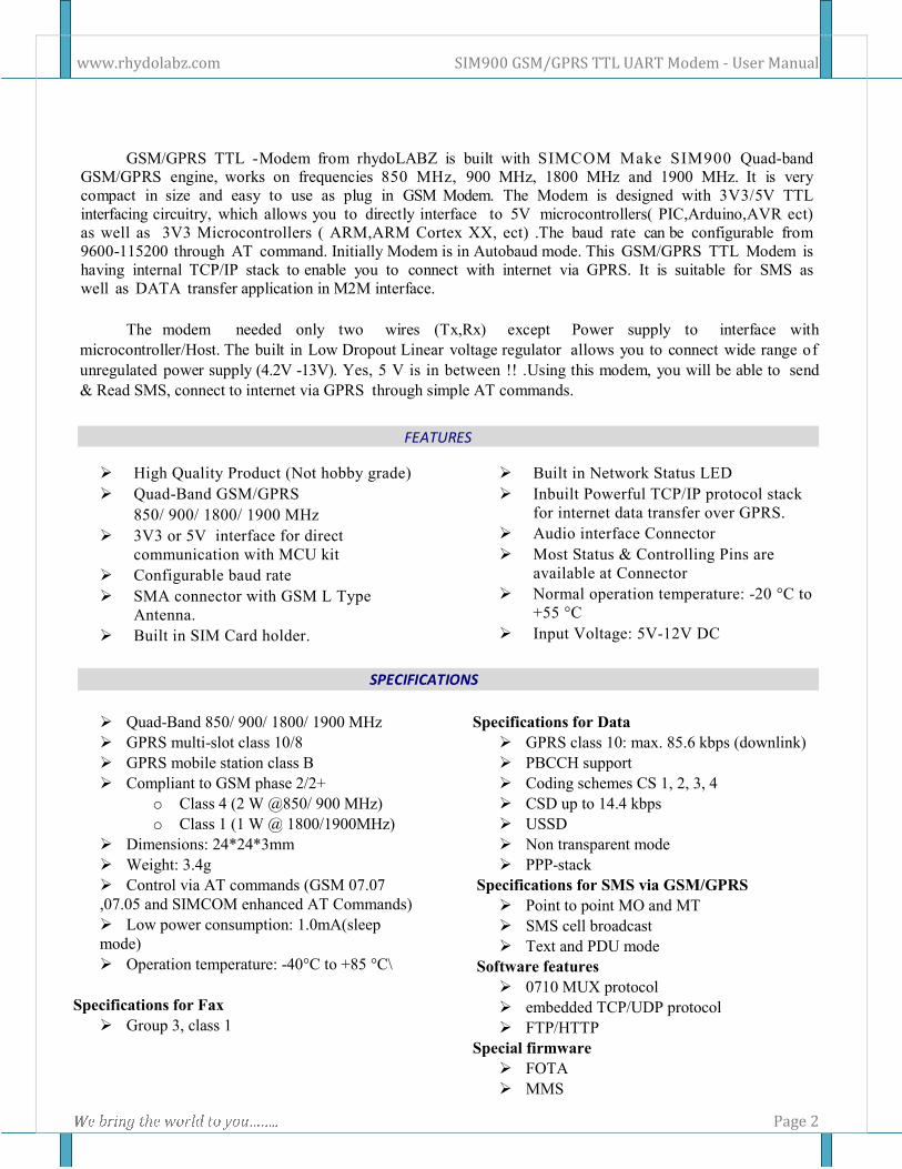
GSM/GPRS TTL -Modem from rhydoLABZ is built with SIMCOM Make SIM900 Quad-band GSM/GPRS engine, works on frequencies 850 MHz, 900 MHz, 1800 MHz and 1900 MHz. It is very
compact in size and easy to use as plug in GSM Modem. The Modem is designed with 3V3/5V TTL
interfacing circuitry, which allows you to directly interface to 5V microcontrollers( PIC,Arduino,AVR ect)
as well as 3V3 Microcontrollers ( ARM,ARM Cortex XX, ect) .The baud rate can be configurable from
9600-115200 through AT command. Initially Modem is in Autobaud mode. This GSM/GPRS TTL Modem is
having internal TCP/IP stack to enable you to connect with internet via GPRS. It is suitable for SMS as
well as DATA transfer application in M2M interface.
The modem needed only two wires (Tx,Rx) except Power supply to interface with
microcontroller/Host. The built in Low Dropout Linear voltage regulator allows you to connect wide range of
unregulated power supply (4.2V -13V). Yes, 5 V is in between !! .Using this modem, you will be able to send
& Read SMS, connect to internet via GPRS through simple AT commands.
FEATURES
� High Quality Product (Not hobby grade)
� Quad-Band GSM/GPRS
850/ 900/ 1800/ 1900 MHz
� 3V3 or 5V interface for direct
communication with MCU kit
� Configurable baud rate
� SMA connector with GSM L Type
Antenna.
� Built in SIM Card holder.
� Built in Network Status LED
� Inbuilt Powerful TCP/IP protocol stack
for internet data transfer over GPRS.
� Audio interface Connector
� Most Status & Controlling Pins are
available at Connector
� Normal operation temperature: -20 °C to
+55 °C
� Input Voltage: 5V-12V DC
SPECIFICATIONS
� Quad-Band 850/ 900/ 1800/ 1900 MHz
� GPRS multi-slot class 10/8
� GPRS mobile station class B
� Compliant to GSM phase 2/2+
o Class 4 (2 W @850/ 900 MHz)
o Class 1 (1 W @ 1800/1900MHz)
� Dimensions: 24*24*3mm
� Weight: 3.4g
� Control via AT commands (GSM 07.07
,07.05 and SIMCOM enhanced AT Commands)
� Low power consumption: 1.0mA(sleep
mode)
� Operation temperature: -40°C to +85 °C\
Specifications for Fax
� Group 3, class 1
Specifications for Data
� GPRS class 10: max. 85.6 kbps (downlink)
� PBCCH support
� Coding schemes CS 1, 2, 3, 4
� CSD up to 14.4 kbps
� USSD
� Non transparent mode
� PPP-stack
Specifications for SMS via GSM/GPRS
� Point to point MO and MT
� SMS cell broadcast
� Text and PDU mode
Software features
� 0710 MUX protocol
� embedded TCP/UDP protocol
� FTP/HTTP
Special firmware
� FOTA
� MMS
www.rhydolabz.com SIM900 GSM/GPRS TTL UART Modem - User Manual
W e b r i n g t h e w o r l d t o y o u … … . . Page 3
� Java (cooperate with Iasolution)
� Embedded AT
Specifications for Voice
� Tricodec
o Half rate (HR)
o Full rate (FR)
o Enhanced Full rate (EFR)
� Hands-free operation
� (Echo suppression)
� AMR
o Half rate (HR)
o Full rate (FR)
Interfaces
� Analog audio interface
� Serial interface
� SMA Antenna Connector
� Seriel Port Pins (RXD,TXD) at 2mm Pitch
RMC
� Seriel Port Status and Controlling Pins at
2mm Pitch RMC
� DC Power pins at 2mm Pitch RMC
Compatibility
� AT cellular command interface
www.rhydolabz.com SIM900 GSM/GPRS TTL UART Modem - User Manual
W e b r i n g t h e w o r l d t o y o u … … . . Page 4
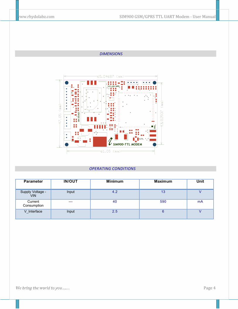
DIMENSIONS
OPERATING CONDITIONS
Parameter IN/OUT Minimum Maximum Unit
Supply Voltage - VIN
Input 4.2 13 V
Current Consumption
--- 40 590 mA
V_Interface Input 2.5 6 V
www.rhydolabz.com SIM900 GSM/GPRS TTL UART Modem - User Manual
W e b r i n g t h e w o r l d t o y o u … … . . Page 5
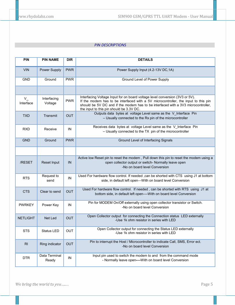
PIN DESCRIPTIONS
PIN PIN NAME DIR DETAILS
VIN Power Supply PWR Power Supply Input (4.2-13V DC,1A)
GND Ground PWR Ground Level of Power Supply
V_
Interface
Interfacing
Voltage PWR
Interfacing Voltage Input for on board voltage level conversion (3V3 or 5V). If the modem has to be interfaced with a 5V microcontroller, the input to this pin should be 5V DC and if the modem has to be interfaced with a 3V3 microcontroller, the input to this pin should be 3.3V DC.
TXD Transmit OUT Outputs data bytes at voltage Level same as the V_Interface Pin
– Usually connected to the Rx pin of the microcontroller
RXD Receive IN Receives data bytes at voltage Level same as the V_Interface Pin
– Usually connected to the TX pin of the microcontroller
GND Ground PWR Ground Level of Interfacing Signals
/RESET Reset Input IN
Active low Reset pin to reset the modem , Pull down this pin to reset the modem using a
open collector output or switch- Normally leave open
-No on board level Conversion
RTS Request to
send IN
Used For hardware flow control. If needed ,can be shorted with CTS using J1 at bottom
side, in default left open—With on board level Conversion
CTS Clear to send OUT Used For hardware flow control. If needed , can be shorted with RTS using J1 at
bottom side, in default left open-—With on board level Conversion
PWRKEY Power Key IN Pin for MODEM On/Off externally using open collector transistor or Switch.
-No on board level Conversion
NETLIGHT Net Led OUT Open Collector output for connecting the Connection status LED externally
-Use 1k ohm resistor in series with LED
STS Status LED OUT Open Collector output for connecting the Status LED externally
-Use 1k ohm resistor in series with LED
RI Ring indicator OUT Pin to interrupt the Host / Microcontroller to indicate Call, SMS, Error ect.
-No on board level Conversion
DTR Data Terminal
Ready IN
Input pin used to switch the modem to and from the command mode
- Normally leave open-—With on board level Conversion
www.rhydolabz.com SIM900 GSM/GPRS TTL UART Modem - User Manual
W e b r i n g t h e w o r l d t o y o u … … . . Page 6
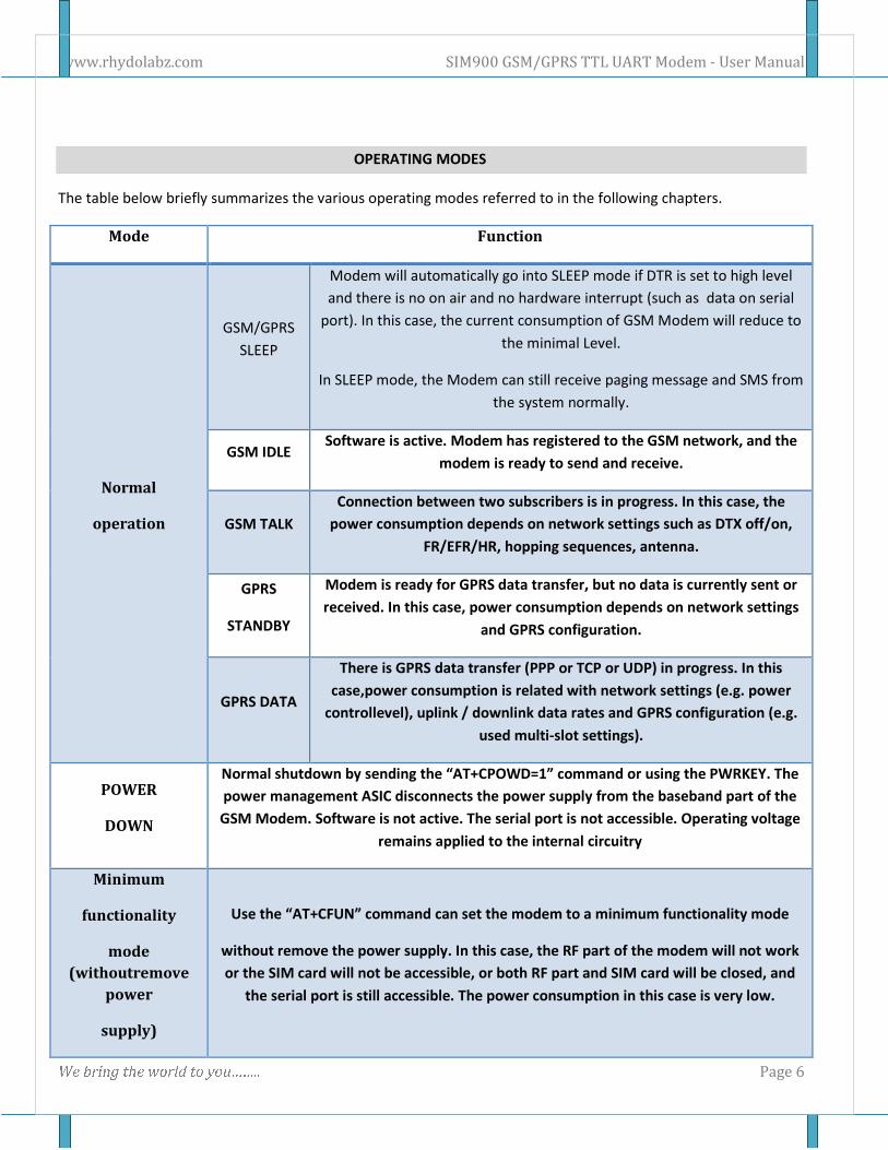
OPERATING MODES
The table below briefly summarizes the various operating modes referred to in the following chapters.
Mode Function
Normal
operation
GSM/GPRS
SLEEP
Modem will automatically go into SLEEP mode if DTR is set to high level
and there is no on air and no hardware interrupt (such as data on serial
port). In this case, the current consumption of GSM Modem will reduce to
the minimal Level.
In SLEEP mode, the Modem can still receive paging message and SMS from
the system normally.
GSM IDLE Software is active. Modem has registered to the GSM network, and the
modem is ready to send and receive.
GSM TALK
Connection between two subscribers is in progress. In this case, the
power consumption depends on network settings such as DTX off/on,
FR/EFR/HR, hopping sequences, antenna.
GPRS
STANDBY
Modem is ready for GPRS data transfer, but no data is currently sent or
received. In this case, power consumption depends on network settings
and GPRS configuration.
GPRS DATA
There is GPRS data transfer (PPP or TCP or UDP) in progress. In this
case,power consumption is related with network settings (e.g. power
controllevel), uplink / downlink data rates and GPRS configuration (e.g.
used multi-slot settings).
POWER
DOWN
Normal shutdown by sending the “AT+CPOWD=1” command or using the PWRKEY. The
power management ASIC disconnects the power supply from the baseband part of the
GSM Modem. Software is not active. The serial port is not accessible. Operating voltage
remains applied to the internal circuitry
Minimum
functionality
mode
(withoutremove
power
supply)
Use the “AT+CFUN” command can set the modem to a minimum functionality mode
without remove the power supply. In this case, the RF part of the modem will not work
or the SIM card will not be accessible, or both RF part and SIM card will be closed, and
the serial port is still accessible. The power consumption in this case is very low.
www.rhydolabz.com SIM900 GSM/GPRS TTL UART Modem - User Manual
W e b r i n g t h e w o r l d t o y o u … … . . Page 7
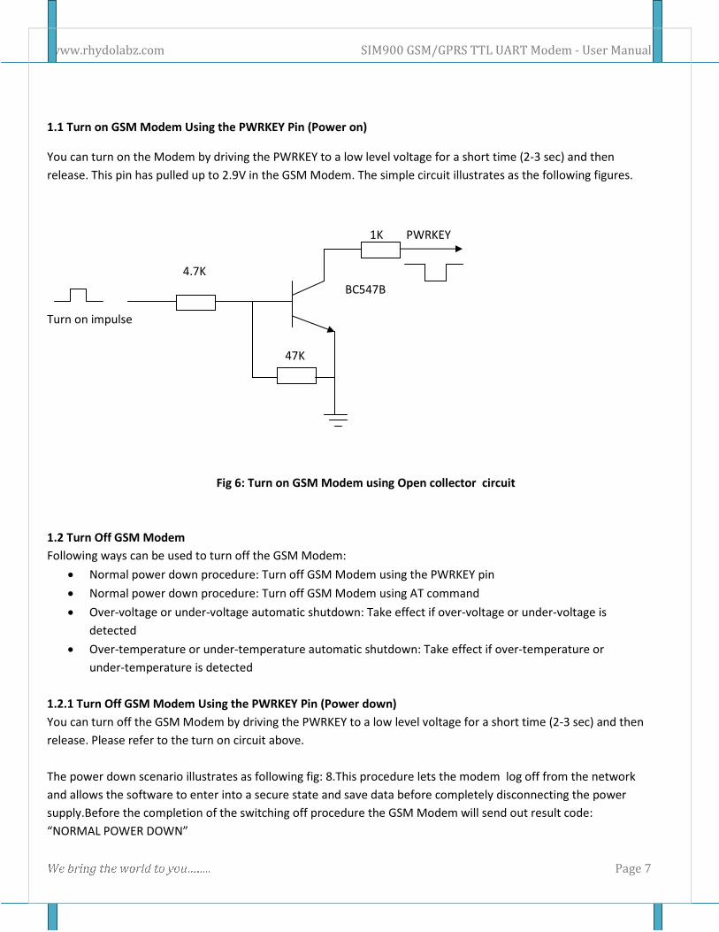
1.1 Turn on GSM Modem Using the PWRKEY Pin (Power on)
You can turn on the Modem by driving the PWRKEY to a low level voltage for a short time (2-3 sec) and then
release. This pin has pulled up to 2.9V in the GSM Modem. The simple circuit illustrates as the following figures.
1K PWRKEY
4.7K
BC547B
Turn on impulse
47K
Fig 6: Turn on GSM Modem using Open collector circuit
1.2 Turn Off GSM Modem
Following ways can be used to turn off the GSM Modem:
• Normal power down procedure: Turn off GSM Modem using the PWRKEY pin
• Normal power down procedure: Turn off GSM Modem using AT command
• Over-voltage or under-voltage automatic shutdown: Take effect if over-voltage or under-voltage is
detected
• Over-temperature or under-temperature automatic shutdown: Take effect if over-temperature or
under-temperature is detected
1.2.1 Turn Off GSM Modem Using the PWRKEY Pin (Power down)
You can turn off the GSM Modem by driving the PWRKEY to a low level voltage for a short time (2-3 sec) and then
release. Please refer to the turn on circuit above.
The power down scenario illustrates as following fig: 8.This procedure lets the modem log off from the network
and allows the software to enter into a secure state and save data before completely disconnecting the power
supply.Before the completion of the switching off procedure the GSM Modem will send out result code:
“NORMAL POWER DOWN”
www.rhydolabz.com SIM900 GSM/GPRS TTL UART Modem - User Manual
W e b r i n g t h e w o r l d t o y o u … … . . Page 8
After this moment, the AT commands can’t be executed. The modem enters the POWER DOWN mode. POWER
DOWN can also be indicated by STATUS pin, which is a low level voltage in this mode.
1.3 Turn Off GSM Modem Using AT Command
You can use the AT command “AT+CPOWD=1” to turn off the modem. This command lets the GSM Modem log off
from the network and allows the GSM Modem to enter into a secure state and save data before completely
disconnecting the power supply. Before the completion of the switching off procedure the GSM Modem will send
out result code:
“ NORMAL POWER DOWN”
After this moment, the AT commands can’t be executed. The GSM Modem enters the POWER DOWN mode, only
the RTC is still active. POWER DOWN can also be indicated by STATUS pin, which is a low level voltage in this
mode.
1.4 Restart GSM Modem Using the PWRKEY Pin
You can restart GSM MODEM by driving the PWRKEY to a low level voltage for a short time(2-3 sec) and then
release, the same as turning on GSM MODEM using the PWRKEY pin. Before restarting the GSM MODEM, you
need delay at least 500ms from detecting the STATUS low level on. The restarting scenario illustrates as the
following figure.
1.5 Power Saving
There are two methods for the GSM Modem to enter into low current consumption status. “AT+CFUN” is used to
set GSM Modem into minimum functionality mode and DTR hardware interface signal can be used to lead system
to be in SLEEP mode (or slow clocking mode).
1.6 Minimum Functionality Mode
Minimum functionality mode reduces the functionality of the GSM Modem to a minimum and, thus, minimizes the
current consumption to the lowest level. This mode is set with the “AT+CFUN” command which provides the
choice of the functionality levels <fun>=0,1,4
• 0: minimum functionality;
• 1: full functionality (default);
• 4: disable phone both transmit and receive RF circuits;
If GSM MODEM has been set to minimum functionality by “AT+CFUN=0”, the RF function and SIM card function
will be closed. In this case, the serial port is still accessible, but all AT commands correlative with RF function or
SIM card function will not be accessible.
If GSM MODEM has been set by “AT+CFUN=4”, the RF function will be closed, the serial port is still active. In this
case all AT commands correlative with RF function will not be accessible.
www.rhydolabz.com SIM900 GSM/GPRS TTL UART Modem - User Manual
W e b r i n g t h e w o r l d t o y o u … … . . Page 9
After GSM MODEM has been set by “AT+CFUN=0” or “AT+CFUN=4”, it can return to full functionality by
“AT+CFUN=1”.
For detailed information about “AT+CFUN”, please refer to document [1].
1.7 Sleep Mode (Slow Clock Mode)
We can control SIM900 GSM Modem to enter or exit the SLEEP mode in customer applications through DTR signal.
When DTR is in high level and there is no on air and hardware interrupt (such as GPIO interrupt or data on serial
port), GSM MODEM will enter SLEEP mode automatically. In this mode, GSM MODEM can still receive paging or
SMS from network but the serial port is not accessible.
Note: For GSM MODEM, it requests to set AT command “AT+CSCLK=1” to enable the sleep mode; the default
value is 0, that can’t make the GSM Modem enter sleep mode. For more details please refer to our AT command
list.
1.8 Wake Up GSM MODEM from SLEEP Mode
When GSM MODEM is in SLEEP mode, the following methods can wake up the GSM Modem.
• Enable DTR pin to wake up GSM MODEM.
If DTR pin is pulled down to a low level,this signal will wake up GSM MODEM from power saving mode.
The serial port will be active after DTR changed to low level for about 50ms.
• Receiving a voice or data call from network to wake up GSM MODEM.
• Receiving a SMS from network to wake up GSM MODEM.
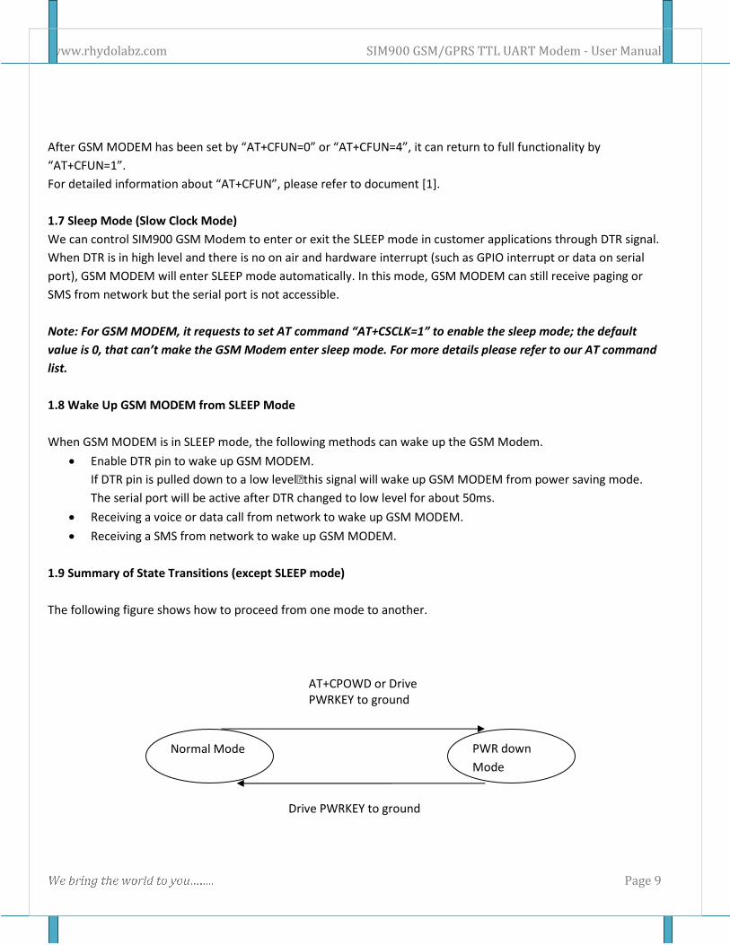
1.9 Summary of State Transitions (except SLEEP mode)
The following figure shows how to proceed from one mode to another.
AT+CPOWD or Drive
PWRKEY to ground
Drive PWRKEY to ground
Normal Mode PWR down
Mode
www.rhydolabz.com SIM900 GSM/GPRS TTL UART Modem - User Manual
W e b r i n g t h e w o r l d t o y o u … … . . Page 10
2.0 Serial Interfaces
The GSM module is designed as a DCE (Data Communication Equipment), following the traditional DCE-DTE (Data
Terminal Equipment) connection. The GSM Modem and the client (DTE) are connected through the following
signal (as following figure shows). Autobauding supports baud rate from 1200bps to 57600bps.
Serial port
• TXD: Send data to the RXD signal line of the DTE
• RXD: Receive data from the TXD signal line of the DTE
serial port of the GSM engine supports autobauding for the following baud rates: 1200, 2400, 4800, 9600,
19200,38400 and 57600bps. Factory setting is autobauding enabled. This gives you the flexibility to put the
GSMengine into operation no matter what baud rate your host application is configured to. To take advantage
ofautobauding mode, specific attention should be paid to the following requirements:
Synchronization between DTE and DCE:
When DCE powers on with the autobauding enabled, user must first send “A” to synchronize the baud rate. It is
recommended to wait 2 to 3 seconds before sending “AT” character. After receiving the “OK” response, DTE and
DCE are correctly synchronized. The more information please refer to the AT command “AT+IPR”.
Restrictions on autobauding operation
• The serial port has to be operated at 8 data bits, no parity and 1 stop bit (factory setting).
• The Unsolicited Result Codes like "RDY", "+CFUN: 1" and "+CPIN: READY” are not indicated when you start
up the ME while autobauding is enabled. This is due to the fact that the new baud rate is not detected
unless DTE and DCE are correctly synchronized as described above.
Note: You can use AT+IPR=x to set a fixed baud rate and save the configuration to non-volatile flash memory.
After the configuration is saved as fixed baud rate, the Unsolicited Result Codes like "RDY" should be received
from the serial port all the time that the GSM MODEM is power on.
AT Command Syntax
When DCE powers on with the autobauding enabled, user must first send “A” to synchronize the baud rate. It is
recommended to wait 2 to 3 seconds before sending “AT” character. After receiving the “OK” response, DTE and
DCE are correctly synchronized The “AT” or “at” prefix must be set at the beginning of each Command. To
terminate a Command line enter <CR> , otherwise known as carriage return or \r.
Commands are followed by a response that includes <CR><LF><response><CR><LF>. Only the responses are
presented in the document here, <CR><LF> are omitted intentionally.
www.rhydolabz.com SIM900 GSM/GPRS TTL UART Modem - User Manual
W e b r i n g t h e w o r l d t o y o u … … . . Page 11
Example: With Local Echo enabled:
Transmit: AT\r
Receive: AT\r\r\nOK\r\n
SETTINGS FOR EASY MICROCONTROLLER COMMUNICATION
When communicating with the GSM Modem using a microcontroller, you usually want very short responses, no
local echo, and no startup messages.
Sticking on the &W to the end of the command saves the setting into memory.
ATV0&W\r Enable short response
ATE0&W\r Disable Local Echo
AT+CIURC=0;&W\r Disable “CALL READY” Startup Message
Now instead of commands returning OK or ERROR in plain text, as well as repeating all written commands, the
GSM Modem will not echo what you transmit and the GSM Modem will return error codes in single bytes. For
example, instead of:
Transmit: AT\r
Receive: \r\nOK\r\n
You’ll have:
Transmit: AT\r
Receive: \r\n0\r\n
SAMPLE AT COMMANDS CODE
1. PHONE COMMUNICATION
Goal: Call a phone
Dial 123-456-7890 = ATD1234567890;\r
This command returns OK or ERROR. Returns NO CARRIER when phone hangs up
2. SEND A TEXT MESSAGE
Goal: Send a text
AT+CMGF=1\r
Returns OK or ERROR
www.rhydolabz.com SIM900 GSM/GPRS TTL UART Modem - User Manual
W e b r i n g t h e w o r l d t o y o u … … . . Page 12
AT+CSCS=”GSM”\r
Returns OK or ERROR
AT+CSCA=”+13123149810” \r
Returns OK or ERROR. This number +13123149810 is the short
message center for AT&T/Cingular service. T-Mobile’s is +12063130004
AT+CSMP=17,167,0,240\r
Returns OK or ERROR. These numbers refer to settings for text
message sending, keep them this way.
AT+CMGS=”
AT+CMGS=”1234567890”\r
Returns > , prompting what message to send. 1234567890 is the
phone number that the text message will be sent to.
Hello this is a message <Ctrl+z>
Type any message, then press <Ctrl+z>. Returns confirmation
message and Message ID number
3. SEND A TEXT MESSAGE
Goal: Read a Text
AT+CMGF=1\r
Returns OK or ERROR
AT+CMGDA=”DEL ALL”
Delete all text
AT+CNMI=0,0
Disable unsolicited error code
AT+CMGR=1
Read Message #1
www.rhydolabz.com SIM900 GSM/GPRS TTL UART Modem - User Manual
W e b r i n g t h e w o r l d t o y o u … … . . Page 13
AT+CMGL=”REC UNREAD”
Read all received unread messages
Debug port
• Null modem port
• Only contain Data lines TXD and RXD
• Debug Port used for debugging and upgrading firmware. It cannot be used for CSD call, FAX call. And the
Debug port can not use multiplexing function. It does not support autobauding function.
• Debug port supports the communication rates is 115200bps
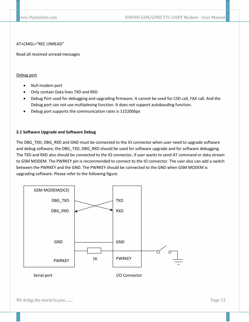
2.1 Software Upgrade and Software Debug
The DBG_TXD, DBG_RXD and GND must be connected to the IO connector when user need to upgrade software
and debug software, the DBG_TXD, DBG_RXD should be used for software upgrade and for software debugging.
The TXD and RXD also should be connected to the IO connector, if user wants to send AT command or data stream
to GSM MODEM. The PWRKEY pin is recommended to connect to the IO connector. The user also can add a switch
between the PWRKEY and the GND. The PWRKEY should be connected to the GND when GSM MODEM is
upgrading software. Please refer to the following figure.
1K
Serial port I/O Connector
GSM MODEM(DCE)
DBG_TXD
DBG_RXD
GND
PWRKEY
TXD
RXD
GND
PWRKEY
www.rhydolabz.com SIM900 GSM/GPRS TTL UART Modem - User Manual
W e b r i n g t h e w o r l d t o y o u … … . . Page 14
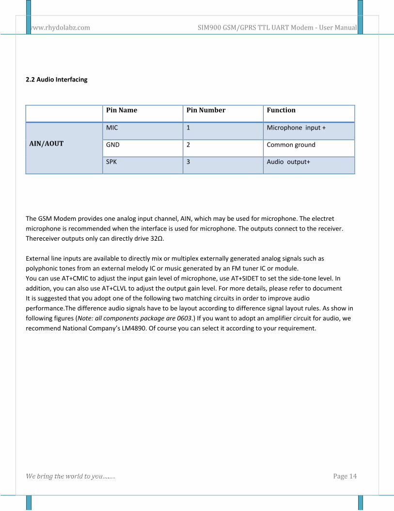
2.2 Audio Interfacing
Pin Name Pin Number Function
AIN/AOUT
MIC 1 Microphone input +
GND 2 Common ground
SPK 3 Audio output+
The GSM Modem provides one analog input channel, AIN, which may be used for microphone. The electret
microphone is recommended when the interface is used for microphone. The outputs connect to the receiver.
Thereceiver outputs only can directly drive 32Ω.
External line inputs are available to directly mix or multiplex externally generated analog signals such as
polyphonic tones from an external melody IC or music generated by an FM tuner IC or module.
You can use AT+CMIC to adjust the input gain level of microphone, use AT+SIDET to set the side-tone level. In
addition, you can also use AT+CLVL to adjust the output gain level. For more details, please refer to document
It is suggested that you adopt one of the following two matching circuits in order to improve audio
performance.The difference audio signals have to be layout according to difference signal layout rules. As show in
following figures (Note: all components package are 0603.) If you want to adopt an amplifier circuit for audio, we
recommend National Company’s LM4890. Of course you can select it according to your requirement.
www.rhydolabz.com SIM900 GSM/GPRS TTL UART Modem - User Manual
W e b r i n g t h e w o r l d t o y o u … … . . Page 15
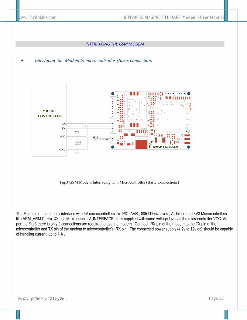
INTERFACING THE GSM MODEM
� Interfacing the Modem to microcontroller (Basic connection)
Fig:3 GSM Modem Interfacing with Microcontroller (Basic Connections)
The Modem can be directly interface with 5V microcontrollers like PIC ,AVR , 8051 Derivatives , Arduinos and 3V3 Microcontrollers like ARM ,ARM Cortex XX ect. Make ensure V_INTERFACE pin is supplied with same voltage level as the microcontroller VCC. As per the Fig:3 there is only 2 connections are required to use the modem . Connect RX pin of the modem to the TX pin of the microcontroller and TX pin of the modem to microcontroller’s RX pin. The connected power supply (4.2v to 12v dc) should be capable of handling current up to 1 A .
www.rhydolabz.com SIM900 GSM/GPRS TTL UART Modem - User Manual
W e b r i n g t h e w o r l d t o y o u … … . . Page 16
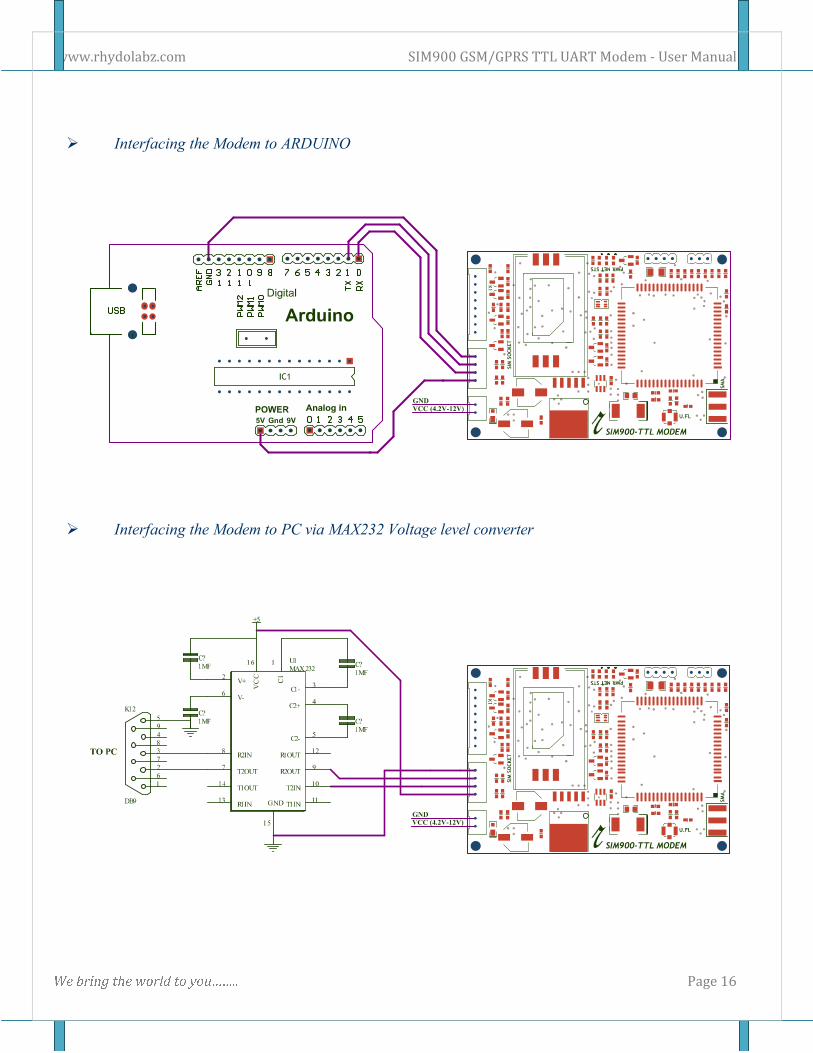
� Interfacing the Modem to ARDUINO
� Interfacing the Modem to PC via MAX232 Voltage level converter
www.rhydolabz.com SIM900 GSM/GPRS TTL UART Modem - User Manual
W e b r i n g t h e w o r l d t o y o u … … . . Page 17
GETTING STARTED
1) Insert SIM card Open the SIM cardholder by sliding it as per the arrow mark and lift up. Insert the SIM card , so as to align
the chamfered corner suits in card holder .After inserting the SIM card, lock the holder by sliding it to the
opposite direction of arrow mark.
2) Connect The Antenna
Fix the Supplied RF antenna to the SMA Antennae connector and tighten it by Rotating the Nut (
Never rotate the antennae for tightening ).
3) Connect the Pins
Connect the GSM modem as per the circuit diagram provided
4) Power the Modem
Power the modem from suitable power supply, which is having enough current capacity (>1A).
5) Check the Status of the LEDs
PWR LED - Red LED will lit immediately
STS LED - Green LED will lit after 1-2 seconds
NET LED -Blue LED will starts to blink in fast for few seconds(Searching For Network) and
becomes slow blinking once the Modem registers with the Network.
6) Network LED
The Network LED indicates the various status of GSM module eg. Power on, Network registration &
GPRS connectivity. When the modem is powered up, the status LED will blink every second. After the
Modem registers in the network (takes between 10-60 seconds), LED will blink in step of 3 seconds. At
this stage you can start using Modem for your application.
7) Baud rate
The Baud rate supported by the modem is between 9600 and 115200. Make sure the host system is set
to the supported baud rate.
� The modem automatically sets to the baud rate of the first command sent by the host system after
it is powered up. User must first send “A” to synchronize the baud rate. It is recommended to wait 2 to 3
seconds before sending “AT” character. After receiving the “OK” response, Your Device and GSM Modem
are correctly synchronized. So there is no need for setting the baud rate using commands.
� Before You Start using the modem, please make sure that the SIM card you inserted support the
needed features and there is enough balance in SIM.!!!
www.rhydolabz.com SIM900 GSM/GPRS TTL UART Modem - User Manual
W e b r i n g t h e w o r l d t o y o u … … . . Page 18
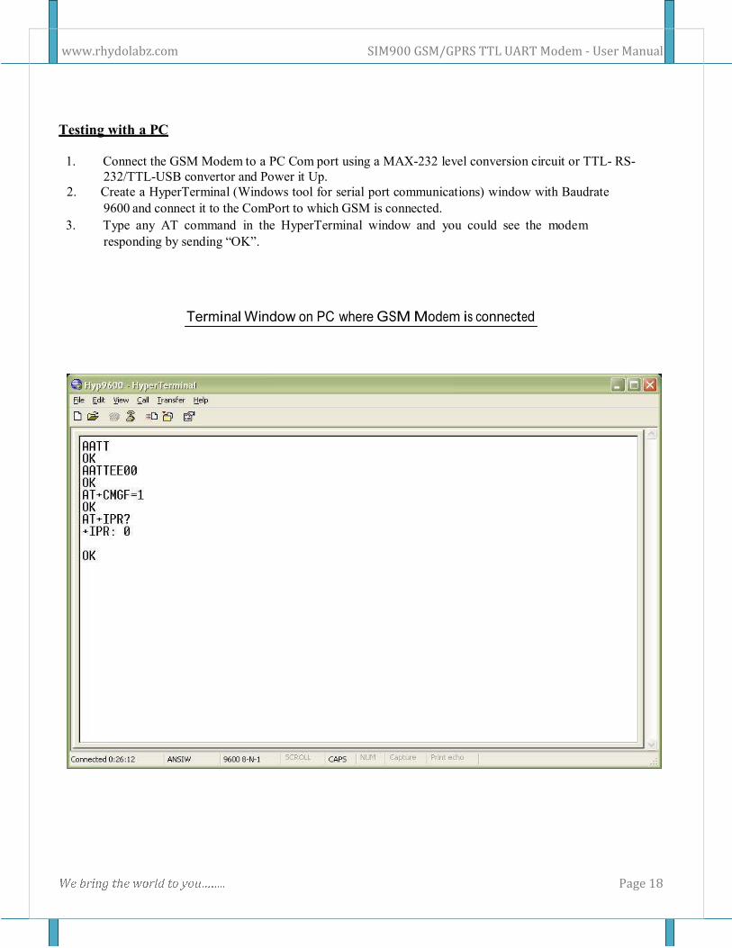
Testing with a PC
1. Connect the GSM Modem to a PC Com port using a MAX-232 level conversion circuit or TTL- RS-
232/TTL-USB convertor and Power it Up.
2. Create a HyperTerminal (Windows tool for serial port communications) window with Baudrate
9600 and connect it to the ComPort to which GSM is connected.
3. Type any AT command in the HyperTerminal window and you could see the modem
responding by sending “OK”.
Terminal Window on PC where GSM Modem is connected
www.rhydolabz.com SIM900 GSM/GPRS TTL UART Modem - User Manual
W e b r i n g t h e w o r l d t o y o u … … . . Page 19
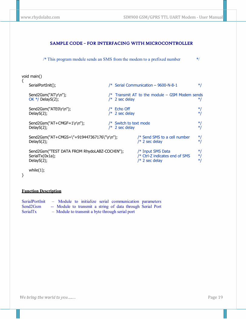
SSSSAAAAMMMMPPPPLLLLEEEE CCCCOOOODDDDEEEE –––– FORFORFORFOR IIIINNNNTTTTEEEERFARFARFARFACCCCIIIINNNNGGGG WWWWIIIITTTTHHHH MMMMIIIICCCCROROROROCCCCOOOONNNNTTTTRRRROOOOLLLLLLLLEEEERRRR
/* This program module sends an SMS from the modem to a prefixed number */
void main() {
SerialPortInit(); /* Serial Communication – 9600-N-8-1 */
Send2Gsm("AT\r\n"); /* Transmit AT to the module – GSM Modem sends OK */ DelayS(2); /* 2 sec delay */
Send2Gsm("ATE0\r\n"); /* Echo Off */ DelayS(2); /* 2 sec delay */
Send2Gsm("AT+CMGF=1\r\n"); /* Switch to text mode */ DelayS(2); /* 2 sec delay */
Send2Gsm("AT+CMGS=\"+919447367176\"\r\n"); /* Send SMS to a cell number */ DelayS(2); /* 2 sec delay */
Send2Gsm("TEST DATA FROM RhydoLABZ-COCHIN"); /* Input SMS Data */ SerialTx(0x1a); /* Ctrl-Z indicates end of SMS */ DelayS(2); /* 2 sec delay */
while(1);
}
Function Description
SerialPortInit – Module to initialize serial communication parameters
Send2Gsm -- Module to transmit a string of data through Serial Port
SerialTx – Module to transmit a byte through serial port
www.rhydolabz.com SIM900 GSM/GPRS TTL UART Modem - User Manual
W e b r i n g t h e w o r l d t o y o u … … . . Page 20
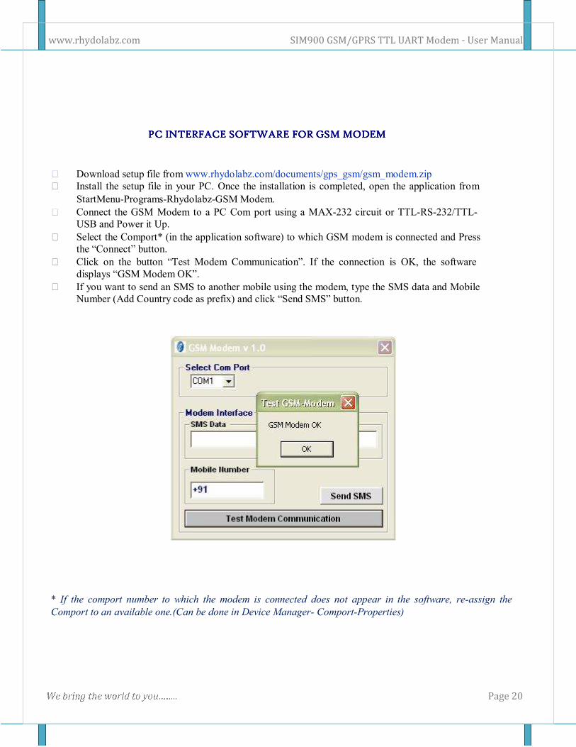
PPPPCCCC IIIINNNNTTTTEEEERRRRFAFAFAFACCCCEEEE SSSSOFOFOFOFTTTTWWWWAREAREAREARE FORFORFORFOR GGGGSSSSMMMM MMMMOOOODDDDEEEEMMMM
Q Download setup file from www.rhydolabz.com/documents/gps_gsm/gsm_modem.zip
Q Install the setup file in your PC. Once the installation is completed, open the application from
StartMenu-Programs-Rhydolabz-GSM Modem.
Q Connect the GSM Modem to a PC Com port using a MAX-232 circuit or TTL-RS-232/TTL-
USB and Power it Up.
Q Select the Comport* (in the application software) to which GSM modem is connected and Press
the “Connect” button.
Q Click on the button “Test Modem Communication”. If the connection is OK, the software
displays “GSM Modem OK”.
Q If you want to send an SMS to another mobile using the modem, type the SMS data and Mobile
Number (Add Country code as prefix) and click “Send SMS” button.
* If the comport number to which the modem is connected does not appear in the software, re-assign the
Comport to an available one.(Can be done in Device Manager- Comport-Properties)
www.rhydolabz.com SIM900 GSM/GPRS TTL UART Modem - User Manual
W e b r i n g t h e w o r l d t o y o u … … . . Page 21
TECHNICAL SUPPORT
If you are experiencing a problem that is not described in this manual, please contact us. Our phone
lines are open from 9:00 AM – 5.00 PM (Indian Standard Time) Monday through Saturday excluding
holidays. Email can be sent to [email protected]
LIMITATIONS AND WARRANTEES
This product is intended for personal or lab experimental purpose and in no case should be used
where it harmfully effect human and nature. No liability will be accepted by the publisher for any consequence
of its use. Use of the product software and or hardware is with the understanding that any outcome whatsoever
is at the users own risk. All products are tested for their best performance before shipping, still rhydoLABZ is
offering One year Free service warranty (Components cost + Shipping cost will be charged from Customer).
DISCLAIMER
Copyright © Rhydo Technologies (P) Ltd
All rights are reserved. Reproduction in whole or in part is prohibited without the prior written consent of the
copyright owner. The information presented in this document does not form part of any quotation or
contract, is believed to be accurate and reliable and may be changed without notice.
Rhydo Technologies (P) Ltd. (An ISO 9001:2008 Certified R&D Company)
Golden Plaza, Chitoor Road,
Cochin – 682018, Kerala State, India Phone : 0091- 484-2370444, 2371666
Cell : 0091- 99466 70444 Fax : 0091 - 484-2370579
E-mail : [email protected], [email protected] WebSite : http://www.rhydolabz.com