Embed Size (px)
Citation preview
Silverstream Pipe Bridge Hydraulic Design Report
Wellington Water Ltd
2 August 2021
The Power of Commitment

The Power of Commitment
GHD Limited [Company number] Grant Thornton House, Level 1, 215 Lambton Quay Wellington, Wellington 6011, New Zealand T +64 4 495 5800 | F +64 4 472 0833 | E [email protected] | ghd.com
Printed date 17/08/2021 3:07:00 PM
Last saved date 17 August 2021 3:07 PM
File name
Author John McArthur
Project manager Steven Kelliher
Client name Wellington Water Ltd
Project name Silverstream Pipe Bridge t
Document title Silverstream Pipe Bridge | Hydraulic Design Report
Revision version Rev [00]
Project number 5137713
Document status
Status Code
Revision Author Reviewer Approved for issue
Name Signature Name Signature Date
00 John McArthur Tony Miller Clive Welling
02/08/2021
© GHD 2021
This document is and shall remain the property of GHD. The document may only be used for the purpose for which it was commissioned and in accordance with the Terms of Engagement for the commission. Unauthorised use of this document in any form whatsoever is prohibited.

GHD | Wellington Water Ltd | 5137713 | Silverstream Pipe Bridge i This document is in draft form. The contents, including any opinions, conclusions or recommendations contained in, or which may be implied from, this draft document must not be relied upon. GHD reserves the right, at any time, without notice, to modify or retract any part or all of the draft document. To the maximum extent permitted by law, GHD disclaims any responsibility or liability arising from or in connection with this draft document.
Contents
1. Introduction 1 1.1 Purpose of this report 1 1.2 Scope and limitations 1 1.3 Assumptions 2
2. Hydraulic Modelling 2 2.1 Design Flood Event 2 2.2 Hydraulic Models 2
2.2.1 MIKE FLOOD Model 2 2.2.2 HecRAS Model 3
2.3 Flooding Assessments 4 2.3.1 HecRAS Model Calibration 4 2.3.2 MIKE FLOOD Outcomes 5 2.3.3 HecRAS Outcomes 5
3. Scour Assessments 6 3.1 Bridge Scour 7 3.2 In-ground Pipe Scour 12
4. Bridge Design Considerations 13 5. References 14
Table index Table 1 Pre and Post Bridge Peak Flood Level Comparison 6 Table 2 Debris Blockage – Estimated Flood Levels 6 Table 3 Soil Material Characteristics 12
Figure index Figure 1 New Pipe Bridge/Pipeline Location 1 Figure 2 HecRAS Model Extent and Cross-section Locations 3 Figure 3 HecRAS model Calibration Comparison 4 Figure 4 1 in 100 Year ARI Flood Extents (1900 m3/s Flood Event) 5 Figure 5 BH 1901 Location 8 Figure 6 Particle Size Distributions 9 Figure 7 BH 1902 Location 9 Figure 8 HecRAS Bridge Scour Extents - Existing River Profile (2800 m3/s Event) 10 Figure 9 HecRAS Pier Numbering 11 Figure 10 HecRAS Bridge Scour Extents – Previous Erosion of Bed and Western Bank
(2800 m3/s Event) 11 Figure 11 Borehole Locations 12

GHD | Wellington Water Ltd | 5137713 | Silverstream Pipe Bridge ii This document is in draft form. The contents, including any opinions, conclusions or recommendations contained in, or which may be implied from, this draft document must not be relied upon. GHD reserves the right, at any time, without notice, to modify or retract any part or all of the draft document. To the maximum extent permitted by law, GHD disclaims any responsibility or liability arising from or in connection with this draft document.

GHD | Wellington Water Ltd | 5137713 | Silverstream Pipe Bridge 1 This document is in draft form. The contents, including any opinions, conclusions or recommendations contained in, or which may be implied from, this draft document must not be relied upon. GHD reserves the right, at any time, without notice, to modify or retract any part or all of the draft document. To the maximum extent permitted by law, GHD disclaims any responsibility or liability arising from or in connection with this draft document.
1. Introduction GHD Limited (GHD) has been engaged by Wellington Water Limited (WWL) to undertake an assessment of flood impacts associated with a new pipe bridge located downstream of the Fergusson Drive and adjacent rail crossing of the Hutt River.
The pipe bridge is required to carry a new pipeline across the Hutt River. This pipeline replaces the existing pipe main which is being decommissioned due to corrosion, an existing alignment via Fergusson Road Bridge which does not meet WWL’s Importance Level (IL) requirements and the alignment along SH2 making repair/maintenance difficult. The pipeline is a critical asset with the consequence of failure extreme.
The location of the pipe bridge and alignment of the in-ground pipe system either side of the bridge is shown in Figure 1.
WWL require the new asset to have an IL of 4. From a flooding perspective, Greater Wellington Regional Council (GWRC) requires any bridge crossing of the main channel of the Hutt River to be designed to a 2800 m3/s design event flood level plus freeboard in accordance with Chapter 3 of their 2001 Hutt River Floodplain Management Plan (HRFMP).
This report has been undertaken to support the wider consent application associated with the bridge crossing of the Hutt River (Section 3) and the pipe alignment through the Manor Park Golf Course (Section 4).
Figure 1 New Pipe Bridge/Pipeline Location
1.1 Purpose of this report This report provides outcomes of the hydraulic (flooding and scour) assessments for use by other members of the multi-disciplinary team involved in the detailed design of the pipe bridge.
1.2 Scope and limitations This report: has been prepared by GHD for Wellington Water Ltd and may only be used and relied on by Wellington Water Ltd for the purpose of the resource consent application for this project.
GHD otherwise disclaims responsibility to any person other than Wellington Water Ltd arising in connection with this report. GHD also excludes implied warranties and conditions, to the extent legally permissible.
Section 3
Section 4

GHD | Wellington Water Ltd | 5137713 | Silverstream Pipe Bridge 2 This document is in draft form. The contents, including any opinions, conclusions or recommendations contained in, or which may be implied from, this draft document must not be relied upon. GHD reserves the right, at any time, without notice, to modify or retract any part or all of the draft document. To the maximum extent permitted by law, GHD disclaims any responsibility or liability arising from or in connection with this draft document.
The services undertaken by GHD in connection with preparing this report were limited to those specifically detailed in the report and are subject to the scope limitations set out in the report.
The opinions, conclusions and any recommendations in this report are based on conditions encountered and information reviewed at the date of preparation of the report. GHD has no responsibility or obligation to update this report to account for events or changes occurring subsequent to the date that the report was prepared.
The opinions, conclusions and any recommendations in this report are based on assumptions made by GHD described in this report (refer section 1.3 of this report). GHD disclaims liability arising from any of the assumptions being incorrect.
GHD has prepared this report on the basis of information provided by Wellington Water Ltd and others who provided information to GHD (including other Government authorities), which GHD has not independently verified or checked beyond the agreed scope of work. GHD does not accept liability in connection with such unverified information, including errors and omissions in the report which were caused by errors or omissions in that information.
1.3 Assumptions - The MIKEFLOOD model provided by GWRC for flood assessments is ‘fit for purpose’.
- River cross-section information included in the GWRC flood model and used in other models set up by GHD is representative of the current Hutt River reach upstream and downstream of the new pipe bridge alignment.
2. Hydraulic Modelling
2.1 Design Flood Event The requirements of the GWRC’s 2001 Hutt River Floodplain Management Plan (HRFMP) have been adopted. The HRFMP requires that the bridge be designed for a 2800 m3/s flood event (equivalent to a return period of approximately 1 in 2800 years).
The HRFMP is based on risk assessment (and acceptable levels of service), with the 2800 m3/s flow rate set by the GWRC to incorporate the risk caused by climate change through to at least 2090, as beyond that time frame estimating flood effects is very uncertain. GWRC has advised that it is unlikely there will be a requirement for an increase in the design standard over the next 70 plus years (email from Sharyn Westlake, GWRC, 11 Feb 2021).
It is worth noting, that the bridge location is in a section of the river where there are no stop banks, and the effects of larger floods (greater than the 2800 m3/s flood) will lead to only limited increases in depth.
GWRC has also advised that freeboard to the underside of the superstructure is to be a minimum of 1900 mm above the 2800 m3/s floodwater level, made up of 900 mm freeboard and 1000 mm for debris clearance (email from Sharyn Westlake, GWRC, 11 Feb 2021).
2.2 Hydraulic Models 2.2.1 MIKE FLOOD Model GWRC has provided their calibrated hydraulic model of the Hutt River and floodplain. This model was previously set up to simulate a range of design flood events and provide a tool for ongoing management and flood protection design work. The model was built using MIKE FLOOD software which dynamically links the Hutt River channel (MIKE 11) with the floodplain (MIKE21). It has been calibrated to the 27 October 1998 event which had a peak flow of 1540 m3/s recorded at the Taita Gorge recorder site, with levels compared against debris levels measured by GWRC staff following the flood event.
For this assessment, the model has been used to establish:

GHD | Wellington Water Ltd | 5137713 | Silverstream Pipe Bridge 3 This document is in draft form. The contents, including any opinions, conclusions or recommendations contained in, or which may be implied from, this draft document must not be relied upon. GHD reserves the right, at any time, without notice, to modify or retract any part or all of the draft document. To the maximum extent permitted by law, GHD disclaims any responsibility or liability arising from or in connection with this draft document.
• Existing 100 year flood extents in the vicinity of the bridge site to enable Contractors to prepare a construction equipment and materials laydown methodology.
• The HecRAS model used to determine potential flood impacts and bridge scour as discussed below.
2.2.2 HecRAS Model A steady state HEC-RAS backwater model has been set up by GHD, extending approximately 1300 m upstream of the proposed pipe bridge and approximately 1000 m downstream.
The cross-sections in the model have been extracted from the MIKE FLOOD model with the surveyed section at the pipe bridge location also included. Sections immediately upstream and downstream of the structure have been interpolated. Cross-section locations and associated model extent are shown in Figure 2.
Both pre and post – bridge models have been set up with the pre – bridge model calibrated to the MIKE FLOOD model under 2800 m3/s flood flow conditions.
Figure 2 HecRAS Model Extent and Cross-section Locations
The post bridge model has been set up based on the layout shown on GHD Civil drawing 51-37713-C303.
For this assessment, the models have been used to establish:
• Flood level impacts upstream of the pipe bridge in the 2800 m3/s event. • Potential bridge scour. • A preliminary assessment of maximum potential scour along the in-ground pipe alignment (Section 4 –
refer Figure 1).

GHD | Wellington Water Ltd | 5137713 | Silverstream Pipe Bridge 4 This document is in draft form. The contents, including any opinions, conclusions or recommendations contained in, or which may be implied from, this draft document must not be relied upon. GHD reserves the right, at any time, without notice, to modify or retract any part or all of the draft document. To the maximum extent permitted by law, GHD disclaims any responsibility or liability arising from or in connection with this draft document.
2.3 Flooding Assessments 2.3.1 HecRAS Model Calibration As outlined above, the HecRAS model has been calibrated against flood levels extracted from the MIKE FLOOD model under 2800 m3/s design flood event conditions. The calibration has involved modifying the roughness in the HecRAS model. Figure 3 compares the MIKE FLOOD (MIKE 11) and resulting HecRAS flood profiles.
Figure 3 HecRAS model Calibration Comparison
Although cross-section extents in the steady state HecRAS model include the floodplain, it cannot fully take into account changes in flow distribution due to ‘break out’ flows from the main River channel into the floodplain. As indicated in Figure 3, the HecRAS model is therefore slightly conservative in terms of flood level. However the calibration is considered acceptable with roughness values reflecting vegetation conditions in the River and adjoining floodplain.

GHD | Wellington Water Ltd | 5137713 | Silverstream Pipe Bridge 5 This document is in draft form. The contents, including any opinions, conclusions or recommendations contained in, or which may be implied from, this draft document must not be relied upon. GHD reserves the right, at any time, without notice, to modify or retract any part or all of the draft document. To the maximum extent permitted by law, GHD disclaims any responsibility or liability arising from or in connection with this draft document.
2.3.2 MIKE FLOOD Outcomes Existing (pre-pipe bridge) 100 year ARI flood extents and depths are shown in Figure 4 and provides potential laydown areas for plant, machinery and materials during the construction phase.
Figure 4 1 in 100 Year ARI Flood Extents (1900 m3/s Flood Event)
2.3.3 HecRAS Outcomes The pipe bridge has been included in the HecRAS model based on the layout shown on GHD Civil drawing 51-37713-C303. There are a number of methods available in HecRAS for modelling losses at bridge structures. In this instance the bridge has been modelled using the energy based method. This approach requires contraction and expansion coefficients for transition losses, with values of 0.3 and 0.5 respectively used.
Pier representation has been based on the following:
• Eight pile sets in total associated with the four pile arrangements, each with a width of 1.75 m Earthworks associated with access to the eastern side of the bridge have also been included in the model.
Estimated pre and post pipe bridge flood levels for the 2800 m3/s event are summarised in Table 1.

GHD | Wellington Water Ltd | 5137713 | Silverstream Pipe Bridge 6 This document is in draft form. The contents, including any opinions, conclusions or recommendations contained in, or which may be implied from, this draft document must not be relied upon. GHD reserves the right, at any time, without notice, to modify or retract any part or all of the draft document. To the maximum extent permitted by law, GHD disclaims any responsibility or liability arising from or in connection with this draft document.
The impact of the new bridge is less than minor with the table showing a flood level increase of 0.03 m immediately upstream of the structure reducing to 0.02 m immediately downstream of the existing rail bridge. There is no flood level impact upstream of the existing Fergusson Drive bridge crossing of the Hutt River or downstream of the new pipe bridge.
As a check, the empirical Yarnell equation has been used to estimate the change in peak water level from just downstream of the pipe bridge to just upstream. A Yarnell pier shape coefficient of 1.05, representative of twin cylinder piers, has been applied with channel velocity and depth characteristics extracted from the HecRAS model. The resulting change in water level is 0.028 m, similar to the modelled outcome using the energy approach of 0.03 m, tabulated below.
Based on the HecRAS model, the peak flood level under the bridge is estimated to be 36.85 m.
There is the possibility that the piers have to be relocated if splinter faults or other issues are encountered in the final stages of the geotechnical investigations or during construction. If the piers either side of the arch bridge component are moved approximately 5 m into the main River channel, there is likely to be an additional minor flood level increase. An empirical Yarnell equation check this increase to be approximately 5 mm. If these piers are moved approximately 5 m further away from the main channel, flood level increases are likely to be reduced.
Table 1 Pre and Post Bridge Peak Flood Level Comparison
HecRAS Chainage Pre Bridge Level (m) Post Bridge Level (m) Difference (m)
4615 39.61 39.61 0.00
4600 Rail/Road Bridge
4581 37.38 37.40 0.02
4462 37.10 37.12 0.02
4389 36.91 36.93 0.02
4349 36.86 36.89 0.03
4340 New Pipe Bridge 36.85
4331 36.84 36.84 0.00
The above impacts do not take account of any debris blockage. A sensitivity analysis of debris effects on post bridge flood levels has been undertaken using the HecRAS model. This has involved applying a debris width and height behind each pile at the pier locations. Two scenarios have assessed as follows:
Scenario 1 – debris width = 5 m, debris height = 1 m
Scenario 2 – debris width = 5 m, debris height = 2 m
Resulting flood levels are summarised in Table 2
Table 2 Debris Blockage – Estimated Flood Levels
HecRAS Chainage Post Bridge Level - No Debris (m)
Debris Scenario 1 Level (m)
Debris Scenario 2 Level (m)
4615 39.61 39.61 39.61
4600 Rail/Road Bridge
4581 37.40 37.40 37.40
4462 37.12 37.12 37.12
4389 36.93 36.93 36.94
4349 36.89 36.89 36.90
4340 New Pipe Bridge
Table 2 indicates debris Scenario 1 does not further increase flood levels upstream of the bridge with only a 10 mm further impact under debris Scenario 2 conditions.

GHD | Wellington Water Ltd | 5137713 | Silverstream Pipe Bridge 7 This document is in draft form. The contents, including any opinions, conclusions or recommendations contained in, or which may be implied from, this draft document must not be relied upon. GHD reserves the right, at any time, without notice, to modify or retract any part or all of the draft document. To the maximum extent permitted by law, GHD disclaims any responsibility or liability arising from or in connection with this draft document.
3. Scour Assessments
3.1 Bridge Scour The HEC-RAS model has also been used to assess potential scour at the new pipe bridge location using outcomes of the hydraulic analysis. Contraction, pier and abutment scour are taken into account in the model based on the methodologies outlined in the Hydraulic Engineering Circular No.18 (HEC No. 18) produced by the US Department of Transportation - Federal Highway Administration (FHWA). Contraction scour and local scour at piers and abutments are computed based on the hydraulic characteristics of the flood event (e.g. flood depth, flood velocity), the bed and bank particle size distribution (D50, D95) and structure characteristics (e.g. pier size, abutment type).
A ground investigation comprising sampling and particle size distribution testing at a number of locations has been undertaken. The particle size distribution of a sample at 8.4 – 9 m depth extracted from BH 1901 has been selected as representative of the bed and bank material. The location of this borehole is shown in Figure 5 with a graph of the particle size distribution shown as Figure 6.
Figure 6 also shows a particle size distribution associated with BH 1902 at a sample depth of 2.5 – 2.7 m. Although this sample is more likely to be representative of the River bank at the bridge location, the gradings are similar and relevant particle size parameters have been based on the BH 1901 sample.
These are:
D50 = 10.8 mm
D95 = 43 mm
The location of BH1902 is shown in Figure 7.

GHD | Wellington Water Ltd | 5137713 | Silverstream Pipe Bridge 8 This document is in draft form. The contents, including any opinions, conclusions or recommendations contained in, or which may be implied from, this draft document must not be relied upon. GHD reserves the right, at any time, without notice, to modify or retract any part or all of the draft document. To the maximum extent permitted by law, GHD disclaims any responsibility or liability arising from or in connection with this draft document.
Figure 5 BH 1901 Location

GHD | Wellington Water Ltd | 5137713 | Silverstream Pipe Bridge 9 This document is in draft form. The contents, including any opinions, conclusions or recommendations contained in, or which may be implied from, this draft document must not be relied upon. GHD reserves the right, at any time, without notice, to modify or retract any part or all of the draft document. To the maximum extent permitted by law, GHD disclaims any responsibility or liability arising from or in connection with this draft document.
Figure 6 Particle Size Distributions
Figure 7 BH 1902 Location
GHD | Wellington Water Ltd | 5137713 | Silverstream Pipe Bridge 10 This document is in draft form. The contents, including any opinions, conclusions or recommendations contained in, or which may be implied from, this draft document must not be relied upon. GHD reserves the right, at any time, without notice, to modify or retract any part or all of the draft document. To the maximum extent permitted by law, GHD disclaims any responsibility or liability arising from or in connection with this draft document.
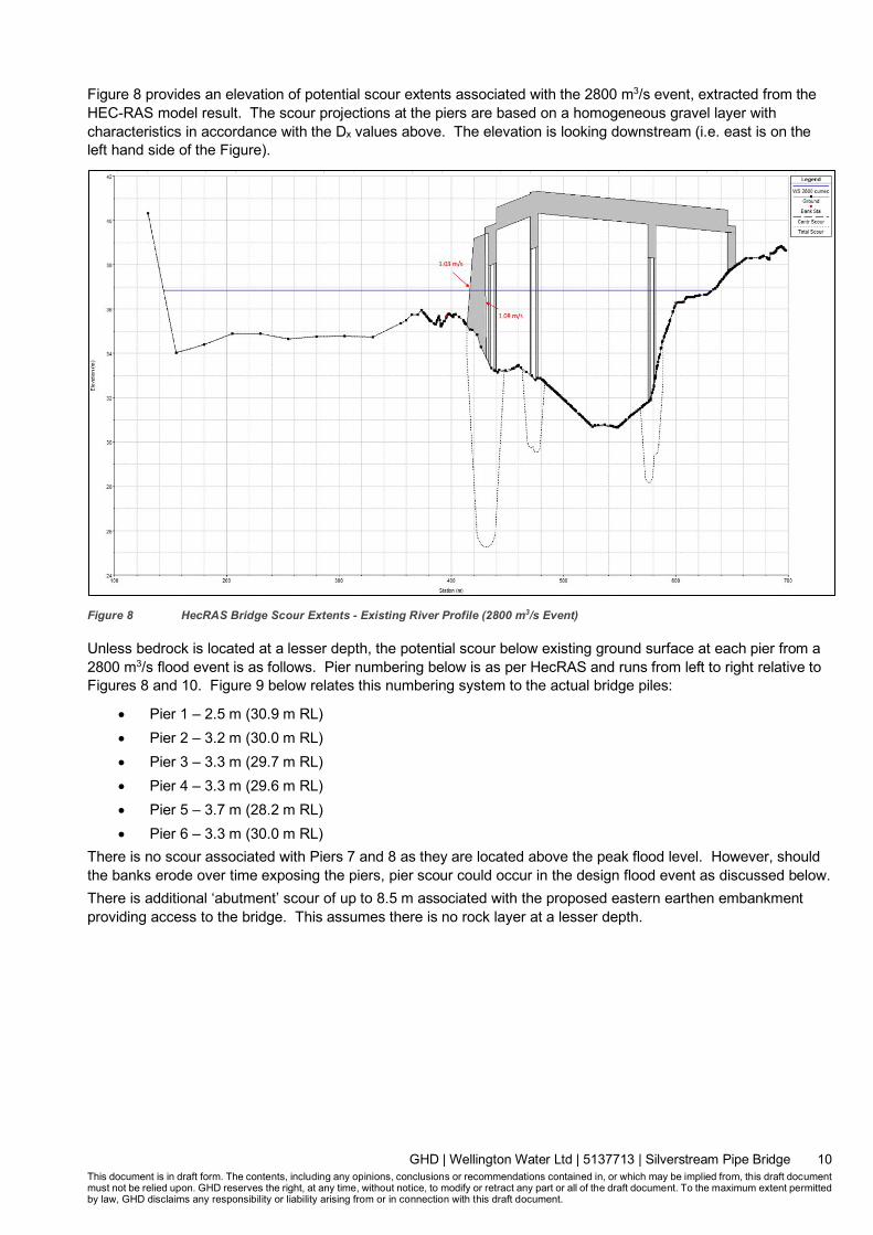
Figure 8 provides an elevation of potential scour extents associated with the 2800 m3/s event, extracted from the HEC-RAS model result. The scour projections at the piers are based on a homogeneous gravel layer with characteristics in accordance with the Dx values above. The elevation is looking downstream (i.e. east is on the left hand side of the Figure).
Figure 8 HecRAS Bridge Scour Extents - Existing River Profile (2800 m3/s Event)
Unless bedrock is located at a lesser depth, the potential scour below existing ground surface at each pier from a 2800 m3/s flood event is as follows. Pier numbering below is as per HecRAS and runs from left to right relative to Figures 8 and 10. Figure 9 below relates this numbering system to the actual bridge piles:
• Pier 1 – 2.5 m (30.9 m RL) • Pier 2 – 3.2 m (30.0 m RL) • Pier 3 – 3.3 m (29.7 m RL) • Pier 4 – 3.3 m (29.6 m RL) • Pier 5 – 3.7 m (28.2 m RL) • Pier 6 – 3.3 m (30.0 m RL)
There is no scour associated with Piers 7 and 8 as they are located above the peak flood level. However, should the banks erode over time exposing the piers, pier scour could occur in the design flood event as discussed below. There is additional ‘abutment’ scour of up to 8.5 m associated with the proposed eastern earthen embankment providing access to the bridge. This assumes there is no rock layer at a lesser depth.

GHD | Wellington Water Ltd | 5137713 | Silverstream Pipe Bridge 11 This document is in draft form. The contents, including any opinions, conclusions or recommendations contained in, or which may be implied from, this draft document must not be relied upon. GHD reserves the right, at any time, without notice, to modify or retract any part or all of the draft document. To the maximum extent permitted by law, GHD disclaims any responsibility or liability arising from or in connection with this draft document.
Figure 9 HecRAS Pier Numbering
As all of the bridge piers (1 – 8) and the eastern embankment are located within the Alluvial Erosion Zone defined in GWRC’s HRFMP, there is potential for the western most set of piers (piers 7 and 8) to be exposed to flood waters in the 2800 m3/s event due to previous erosion. This bridge scour scenario has also been modelled and Figure 10 provides an elevation showing potential scour extents extracted from the HEC-RAS model. Once again, the elevation is looking downstream (i.e. east is on the left hand side of the Figure).
Figure 10 HecRAS Bridge Scour Extents – Previous Erosion of Bed and Western Bank (2800 m3/s Event)
As previously advised, unless bedrock is located at a lesser depth, the potential scour below the modified ground surface at the western most piers from a 2800 m3/s flood event is as follows:
• Pier 7 – 2.0 m (32.7 m RL) • Pier 8 – 1.8 m (34.0 m RL)

GHD | Wellington Water Ltd | 5137713 | Silverstream Pipe Bridge 12 This document is in draft form. The contents, including any opinions, conclusions or recommendations contained in, or which may be implied from, this draft document must not be relied upon. GHD reserves the right, at any time, without notice, to modify or retract any part or all of the draft document. To the maximum extent permitted by law, GHD disclaims any responsibility or liability arising from or in connection with this draft document.
3.2 In-ground Pipe Scour A preliminary assessment of potential maximum scour along the Section 4 in-ground pipe alignment shown in Figure 1 has also been undertaken. As advised by WWL, both a 100 year ARI and 2800 m3/s flood event have been applied to this assessment. An empirical approach using the Farraday and Charlton equations with velocity and flood depths extracted from the HecRAS model has been used.
As indicated above, ground investigation comprising sampling and particle size distribution testing at a number of locations has been undertaken. Figure 11 shows the locations of boreholes from which particle size distributions have been extracted.
For the eastern pipe alignment between the existing bridges and the pipe bridge, BH 1905 soil characteristics have been used. Similarly for the western pipe alignment between the pipe bridge and SH 2, BH’s 2005, 2007 and 2008 soil characteristics have been used. These characteristics are summarised in Table 3.
Table 3 Soil Material Characteristics
Borehole D50 (mm) D90 (mm)
BH 2005 (western pipe alignment) 1.2 41
BH 2007 (western pipe alignment) 3 39
BH 2008 (western pipe alignment) 4.75 30
Figure 11 Borehole Locations
In the 100 year ARI event, the assessment indicates potential scour depths of less than 200 mm along sections of the Section 4 western alignment where the pipe trench is below the 100 year ARI flood level. This scour depth is less than the proposed pipe depth of 1 to 1.5 m. Based on the HecRAS model results, maximum velocities up to 1.5 m/s in the vicinity of the pipe alignment could occur.
Similarly, in the 2800 m3/s flood event, the assessment indicates potential scour depths of less than 1000 mm along sections of the Section 4 western alignment where the pipe trench is below the flood level. This scour depth

GHD | Wellington Water Ltd | 5137713 | Silverstream Pipe Bridge 13 This document is in draft form. The contents, including any opinions, conclusions or recommendations contained in, or which may be implied from, this draft document must not be relied upon. GHD reserves the right, at any time, without notice, to modify or retract any part or all of the draft document. To the maximum extent permitted by law, GHD disclaims any responsibility or liability arising from or in connection with this draft document.
is less than the proposed pipe depth of 1 to 1.5 m. Based on the HecRAS model results, maximum velocities up to 2.5 m/s in the vicinity of the pipe alignment could occur.
4. Bridge Design Considerations Flood Management
The requirements of the GWRC’s 2001 Hutt River Floodplain Management Plan (HRFMP) have been adopted. The HRFMP requires that the bridge be designed for a 2800 m3/s flood event (equivalent to a return period of approximately 1 in 2800 years).
The HRFMP is based on risk assessment (and acceptable levels of service), with the 2800 m3/s flow rate set by the GWRC to incorporate the risk caused by climate change through to at least 2090, as beyond that time frame estimating flood effects is very uncertain. GWRC has advised that it is unlikely there will be a requirement for an increase in the design standard over the next 70 plus years (email from Sharyn Westlake, GWRC, 11 Feb 2021).
It is worth noting, that the bridge location is in a section of the river where there are no stop banks, and the effects of larger floods (greater than the 2800 m3/s flood) will lead to only limited increases in depth.
GWRC has advised that freeboard to the underside of the superstructure is to be a minimum of 1900 mm, made up of 900 mm freeboard and 1000 mm for debris clearance (email from Sharyn Westlake, GWRC, 11 Feb 2021).
To meet GWRC requirements, the underside of the bridge superstructure is a minimum 1.9 m above the estimated 2800 m3/s floodwater level at the bridge alignment of 36.85 m RL (i.e. a minimum level of 38.75 m RL).
For the design of the bridge, GHD has also adopted the requirements of the Waka Kotahi Bridge Manual. Although the Bridge Manual is primarily for bridges procured by Waka Kotahi, GHD consider it a solid basis for a design at this importance level. The Bridge Manual 3rd edition requires the bridge to be designed for a 1/2500 year flood event (Amendment 3, Table 2.1) with a 1.2 m freeboard (Table 2.4 ). Clause 2.3.2c of the Manual states that if the bridge cannot be retrofitted for future climate change, climate change impacts shall be taken into account. Over the life of the bridge, the additional 700 mm of freeboard required by GWRC will accommodate any increase in flood levels due to climate change. Any additional scour to the piles due to climate change impacts will be managed through adaptive scour protection measures where required, as indicated below.
Scour Management in Pier Design The piers have been designed for potential scour as follows:
1. Eastern Piers – Piers 2 to 4 (Refer GHD Civil drawing 51 -37713-C303) The analysis indicates that except for the western most set of piles in the Pier 2 configuration, localised scour could occur to bedrock level in both the current river profile and assumed future riverbed profile. The piles have been designed with sufficient capacity and embedment depth to withstand a 2800 m3/s flood event which could potentially erode the river bed down to the bedrock. No scour protection will be required for the piers or the river bank on the eastern side. However, as the piers sit within public reserve land, reinstatement of eroded material could be considered for aesthetic purposes. Following a significant flood event where localised scour occurs, it is recommended that rock and soil material in the vicinity be used to reinstate around the piers to the pre-existing ground level.
2. Western Pier – Pier 1 (Refer GHD Civil drawing 51 -37713-C303) For the current river bed profile, the analysis indicates that no scour is expected at Pier 1. The pier is located approximately 60 m from the current active channel and river levels in a 2800 m3/s event are not expected to extend to this location. For the present case, no scour protection is required at Pier 1. If the river were to erode the banks on the western side and the channel bank migrated 80 metres, scour to approximately 32m RL could occur at Pier 1. The piles have been designed to withstand scour of material down to this level by way of a steel pile sleeve down to this depth. Armouring the western bank to prevent movement of the river channel was also considered as part of the design process. To maintain the channel in its current location would require extensive protection

GHD | Wellington Water Ltd | 5137713 | Silverstream Pipe Bridge 14 This document is in draft form. The contents, including any opinions, conclusions or recommendations contained in, or which may be implied from, this draft document must not be relied upon. GHD reserves the right, at any time, without notice, to modify or retract any part or all of the draft document. To the maximum extent permitted by law, GHD disclaims any responsibility or liability arising from or in connection with this draft document.
measures and would not be aligned with the parameters for the Erosion Zone as specified in the HRFMP. Having said that, significant channel migration at this location is unlikely. A review of historical aerial photographs has shown no significant erosion or movement of the river channel on the western side in the last century. On this basis, no scour protection for the western bank is recommended at this time. However, if there are signs of erosion of the river bed or the banks in the vicinity of Pier 1, GHD recommend that localised scour protection or bank stabilisation works be implemented. The Bridge Operations Manual will provide direction as to the amount of scouring that can be allowed to occur before these measures are implemented.
Scour Management in Embankment Design An earthen embankment will be constructed on the eastern side of the bridge to provide access to the bridge for cyclists, pedestrians and maintenance vehicles. The embankment does not provide structural support for the bridge. As the embankment is for access to the bridge and is not a structural element of the bridge, it is not designed to the same 2800 m3/s flood criteria. In the event of a significant flood event at Silverstream, the eastern embankment may be undermined. However, access to the bridge will still be possible from the western side as no erosion is expected at the western access point in the current river channel location. The embankment will be constructed with Duramesh facing under the bridge on the river side and reinforced soil throughout. The Duramesh facing is designed to withstand moderate flood velocities and modelling indicates maximum velocities of 1.1 m/s adjacent to this face which is within the design range of the product.
In the case of a 2800 m3/s flood event or where over time the channel bank migrates 80 m east (up to the edge of the Erosion Zone), the embankment will be undermined. In the 2800 m3/s event, this will be a combination of pier scour encroaching on the embankment toe as well as scour at the embankment itself. Although this will not compromise the structural integrity of the bridge, cyclist, vehicle and pedestrian access will be impeded. Although this embankment is required for rapid maintenance after a seismic event, in a flood event the bridge height mitigates damage to the pipe. In this flood situation, access is not required for maintenance purposes and therefore can be restored after the flood event. However GHD recommend that if there are signs of significant erosion approaching the eastern embankment and the road, localised scour protection or bank stabilisation works be implemented. In addition, there is the potential for a section of the in-ground pipe system adjacent to the eastern embankment to be exposed following embankment scour or if there is a breach of the embankment from floodwaters on the Eastern Hutt Road side. Consideration will therefore need to be given to providing rock protection on and adjacent to both sides of the embankment in detail design.
5. References GWRC Hutt River Floodplain Management Plan – October 2001
US Army Corps of Engineers, HEC-RAS River Analysis System User’s Manual, version 5.0 – Feb 2016
Hutt Model Upgrade – Hydraulic Modelling prepared by DHI for GWRC - November 2018

GHD | Wellington Water Ltd | 5137713 | Silverstream Pipe Bridge 15 This document is in draft form. The contents, including any opinions, conclusions or recommendations contained in, or which may be implied from, this draft document must not be relied upon. GHD reserves the right, at any time, without notice, to modify or retract any part or all of the draft document. To the maximum extent permitted by law, GHD disclaims any responsibility or liability arising from or in connection with this draft document.
ghd.com The Power of Commitment