Embed Size (px)
Citation preview
THE PARAMETRIC DESIGN OF A STEEL PIPE BRIDGE
Creation of a parametric model
Bachelor’s thesis
Hämeenlinna University Centre, Degree Programme in Construction and Civil Engineering
Spring 2021
Darya Samoilova
Construction and Civil Engineering, Bachelor of Engineering Abstract
Author Darya Samoilova Year 2021
Subject The Parametric Design of a Steel Pipe Bridge
Supervisor Cristina Tirteu
Pipeline bridges are a vital part of a process plant. Their design process is time-consuming,
facing constant updates from involved technology groups. These structures have repetitive
geometry, which makes them suitable for automation. At the moment new approaches of
the parametric design could be applied for this purpose, as it allows the development of
easily adjustable models.
The thesis aims to create a parametric model for the steel pipe bridge to be applied in the
early stages of the project, thereby facilitating the design process. The thesis consists of
descriptions of pipeline bridges, their configuration, types, and sizes, which are later
embodied in a parametric model.
The visual programming tool Grasshopper in Rhinoceros 7 was used for scripting the
parametric algorithm, which was also fully integrated into Tekla Structures. The workability
of the developed algorithm was proved by carrying out a series of tests, which showed the
speed and accuracy of the implementation of the desired shapes. The algorithm has the
potential to be used by structural engineers for setting the basic structure of the pipe bridge
ready for further detailing.
Keywords Pipeline bridge, parametric design, Grasshopper, Tekla Structures, Rhinoceros,
visual programming
Pages 34 pages and appendices 4 pages
Contents
1 INTRODUCTION .......................................................................................................... 1
1.1 Background ...................................................................................................... 1
1.2 Aim and limitations .......................................................................................... 2
2 KNOWLEDGE BASE ..................................................................................................... 2
2.1 Pipeline bridge ................................................................................................. 2
2.2 Process piping .................................................................................................. 3
2.2.1 Pipes ..................................................................................................... 3
2.3 Considerations ................................................................................................. 4
2.4 Sizing ................................................................................................................ 6
2.5 Types ................................................................................................................ 7
2.6 Structural elements of a pipeline bridge ......................................................... 8
2.7 Material ............................................................................................................ 9
2.8 Cross-sections ................................................................................................ 10
2.9 Parametric Associative Design ....................................................................... 10
2.9.1 Potential of parametric modeling in construction engineering......... 11
3 METHODS ................................................................................................................. 12
4 SOFTWARE ................................................................................................................ 12
4.1 Rhinoceros 3D ................................................................................................ 13
4.2 Grasshopper ................................................................................................... 13
4.2.1 Interface ............................................................................................. 13
4.3 Tekla live-link.................................................................................................. 14
4.4 Tekla BIM........................................................................................................ 15
5 PARAMETRIC MODEL OF THE PIPELINE BRIDGE ...................................................... 15
5.1 Development Concept ................................................................................... 15
5.2 Parameters ..................................................................................................... 16
5.3 Creation of geometry of pipeline bridge ....................................................... 18
5.4 Integration with Tekla .................................................................................... 25
5.5 Tests ............................................................................................................... 26
5.5.1 Test 1 .................................................................................................. 26
5.5.2 Test 2 .................................................................................................. 28
6 CONCLUSION ............................................................................................................ 31
6.1 Further use ..................................................................................................... 32
REFERENCES ..................................................................................................................... 33

Appendices
Appendix 1 Documentation for Test 1
Appendix 2 Documentation for Test 2
1
1 INTRODUCTION
1.1 Background
Pipeline bridges are sometimes referred to as the "arteries" of an entire process plant as they
support the pipeline laid throughout the plant's layout. They belong to non-building structures,
and each pipeline bridge system is usually designed from scratch following the facility's needs, as
there is no ready-made solution. In most cases, it is a structure with repetitive elements where the
structure's functionality is valued over appearance. Since an inadequate design of pipe bridge may
lead to defects and improper sizing in structures, this vital area requires considerable planning and
coordination with other technology groups regarding construction. In real life, the final piping,
equipment, and load information are not available at an early stage in most projects. The initial
design can be updated multiple times over the project's life cycle, which is time and cost-
consuming for all parties involved.
Construction companies are always looking for ways to make the design process more efficient,
either by developing standardized solutions or suggesting different work approaches. The
conventional way of designing pipeline bridges is a long step-by-step process, where a single
change requires remaking everything.
The use of parametric modeling greatly simplifies this process, as the geometry of the parametric
model can be quickly adjusted by modifying specific parameters according to the project's
changes. It also allows analyzing and testing a variety of design results from basic concept design
to construction documentation stages. This approach gives more control over the design to the
contractors and provides a better understanding of the process to the clients. Studying
relationships and incorporating fundamental aspects of the actual construction, such as material,
structural properties, and manufacturing technologies, into the design process became possible
using parametric software (Kalsi, 2015). Therefore, this thesis will consider the ways of integrating
parametric design at the early stages of designing a pipe bridge.
2
1.2 Aim and limitations
The thesis aims to create a parametric model of the steel pipe bridge for use in the early stages of
the project, thereby facilitating design. The developed parametric model should include all the
main elements of the pipeline bridge structure and should be able to control its properties. Using
this model, even with a small amount of information available, the start of the modeling process
of the pipeline bridge should be possible. By manipulating the values of the parameters, the main
view of the pipe rack can be set and immediately integrated into the BIM (Building Information
Modeling) software for further modeling or used as a model for calculations. Depending on the
project, each pipeline bridge has distinctive characteristics that may go beyond the capabilities of
the developed model. In this case, the algorithm can be used as a base or modified, taking into
account new features.
2 KNOWLEDGE BASE
2.1 Pipeline bridge
A pipeline bridge, also known as a pipe rack, is an essential frame structure in a process plant. It
carries pipes and cable trays from one piece of equipment to another within one process unit or
from one unit to another.
The choice of design and solution for pipe racks is based on building codes, standards, regulations,
and legislation. When it comes to European standards, pipeline bridges should be built according
to Eurocodes and National Annexes. However, the methods of determining loads in there are not
fully compatible with pipe bridge structures as they are not part of conventional buildings and
structures. Specific design criteria for such systems are challenging to identify.
Previous works on this topic were mainly focused on the conventional design methods for specific
cases, while this thesis considers the parametric approach to make a universal model that can be
applied in various projects.
3
2.2 Process piping
The importance of a pipe rack is that it supports and routes all process piping, which in turn
regulates the flow of a wide range of fluids and gases in industrial environments. According to
Moran (2017, p. 483), the piping layout can constitute about 30% of the capital cost of the plant
therefore it has a major influence on the economics of plant design. The ultimate goal is to provide
a cost-effective and simple yet flexible layout. The choice of design, materials, and manufacturing
method for piping systems should be based on standards and codes determined for a specific
plant, location, and other factors.
2.2.1 Pipes
The pipe rack serves as a carrier for a variety of pipelines. It is essential to identify these pipelines
before beginning the pipeline bridge design. It is customary to place different types of lines on
certain parts of the pipe rack. Process lines, relief-line headers, and utility headers are the three
types of pipelines guided in the pipe bridges that are defined by Bausbacher & Hunt (1993).
1. Process lines are a group of pipes that serves different needs. Process lines connect nozzles
on process equipment that are separated by more than 6 meters, product lines that run
from vessels, exchangers, or pumps to the unit limits to storage or header arrangement
outside the plant, charge lines that connect to exchangers, furnaces, or other process
equipment.
2. The relief header is a piping system that connects all the relief valve outputs into a single
pipe or header, leading to the relief scrubber and then to the vent.
3. There are two types of utility lines in the pipeline bridge: utility headers that provide
service to all the plant's facilities and utility lines that serve one or two pieces of equipment
in the plant.
Pipe placing
Process lines are usually carried on the lower tier of pipe racks, while utility lines are held on the
top. Heavy lines with large diameters are mounted over or near the pipe bridge columns,
regardless of function. Shorter pipe runs, savings on piping costs, and better process flow
4
conditions are ensured by placing process lines in the lower tiers (Drake & Walter, 2010). In case
of leakage of aggressive or flammable process materials, such a layout eliminates the risk of
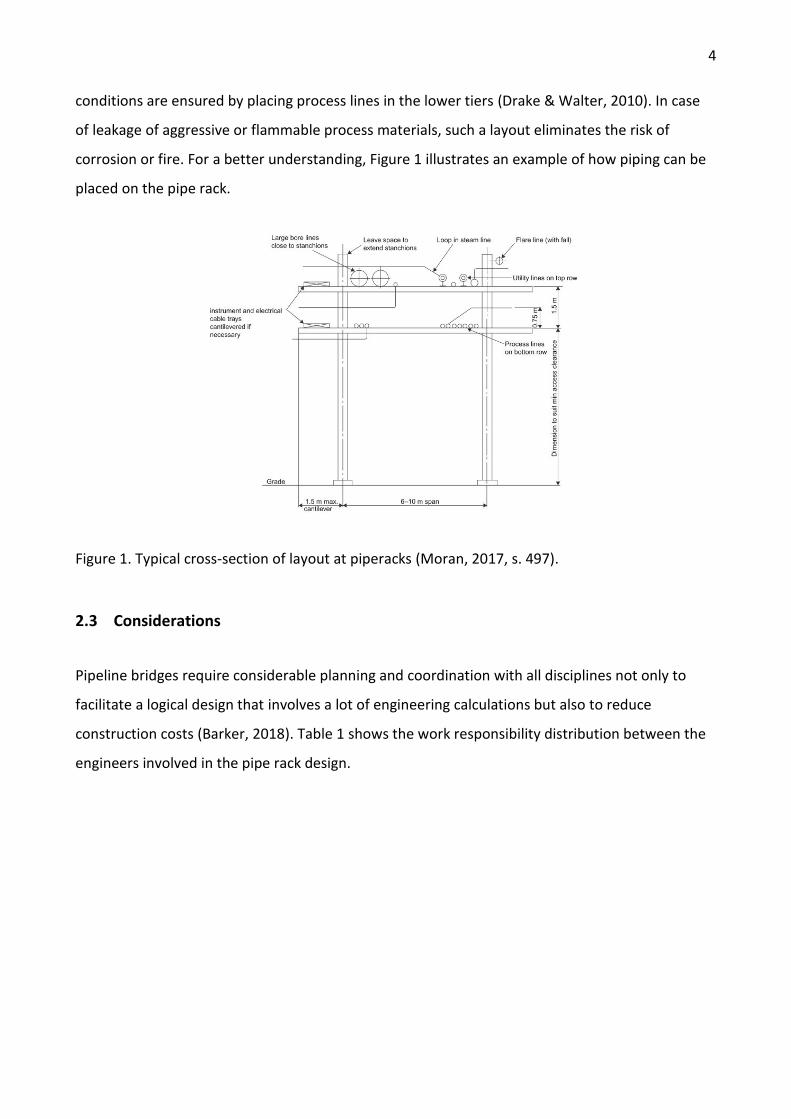
corrosion or fire. For a better understanding, Figure 1 illustrates an example of how piping can be
placed on the pipe rack.
Figure 1. Typical cross-section of layout at piperacks (Moran, 2017, s. 497).
2.3 Considerations
Pipeline bridges require considerable planning and coordination with all disciplines not only to
facilitate a logical design that involves a lot of engineering calculations but also to reduce
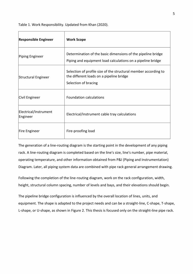
construction costs (Barker, 2018). Table 1 shows the work responsibility distribution between the
engineers involved in the pipe rack design.
5
Table 1. Work Responsibility. Updated from Khan (2020).
Responsible Engineer Work Scope
Piping Engineer Determination of the basic dimensions of the pipeline bridge
Piping and equipment load calculations on a pipeline bridge
Structural Engineer
Selection of profile size of the structural member according to the different loads on a pipeline bridge
Selection of bracing
Civil Engineer Foundation calculations
Electrical/Instrument Engineer
Electrical/Instrument cable tray calculations
Fire Engineer Fire-proofing load
The generation of a line-routing diagram is the starting point in the development of any piping
rack. A line-routing diagram is completed based on the line's size, line's number, pipe material,
operating temperature, and other information obtained from P&I (Piping and Instrumentation)
Diagram. Later, all piping system data are combined with pipe rack general arrangement drawing.
Following the completion of the line-routing diagram, work on the rack configuration, width,
height, structural column spacing, number of levels and bays, and their elevations should begin.
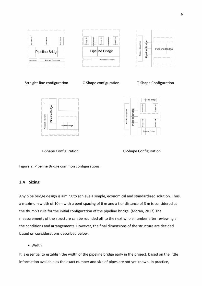
The pipeline bridge configuration is influenced by the overall location of lines, units, and
equipment. The shape is adapted to the project needs and can be a straight-line, C-shape, T-shape,
L-shape, or U-shape, as shown in Figure 2. This thesis is focused only on the straight-line pipe rack.
6
Straight-line configuration C-Shape configuration T-Shape Configuration
L-Shape Configuration U-Shape Configuration
Figure 2. Pipeline Bridge common configurations.
2.4 Sizing
Any pipe bridge design is aiming to achieve a simple, economical and standardized solution. Thus,
a maximum width of 10 m with a bent spacing of 6 m and a tier distance of 3 m is considered as
the thumb's rule for the initial configuration of the pipeline bridge. (Moran, 2017) The
measurements of the structure can be rounded off to the next whole number after reviewing all
the conditions and arrangements. However, the final dimensions of the structure are decided
based on considerations described below.
• Width
It is essential to establish the width of the pipeline bridge early in the project, based on the little
information available as the exact number and size of pipes are not yet known. In practice,
7
designing with an additional 20–50% width allowance for plant expansion is recommended. Rack
widths can be changed to suit the needs of the plant they support, rather than being constant in
the facility. A two-level rack can be used where a width greater than 10 m is needed to
accommodate all the piping, with the second level 1.5 m above the first.
• Height
The height of the rack is determined based on the largest pipeline size supported by the structure
and the size of the branch so that all the small branches can be accommodated in the gap
between tier to tier. Branching from both sides top and the bottom should be considered. (Khan,
2020)
Moran (2017) asserts that when vehicular access underneath the pipeline rack is not needed, a
minimum elevation of 3.6 m is sufficient. Vehicles must ride under racks that are at least 4.5
meters above plant paving or road surfaces. The clearance of 4.5 meters under the rack is enough
for most road vehicles. If cranes/equipment movement under the pipeline bridge or rail crossing is
required, a minimum height is 6 m and 7 m, respectively.
• Length
The length of the piping bridge is calculated using a unit plot plan. It depends on several factors,
such as the number of units and the plant's size.
• Spacing
The distance between the columns of pipe racks should be determined by taking into account the
economics of the pipe span and the structure of the truss to provide a double span for crossing the
road or avoiding underground obstacles.
2.5 Types
The existence of various types of pipeline bridges is due to differences in the project's needs;
therefore, before starting the design, it is necessary to decide which type to use. Three types of
pipe bridges can be defined: continuous pipeline bridge (conventional) system, non-continuous
pipeline bridge system, modular pipeline bridge.
• Conventional pipeline bridges
8
Conventional pipe rack systems consist of frame assemblies with the transverse beams and the
columns connected by the longitudinal struts and the vertical bracing. Beam struts provide
longitudinal stability and support for transverse pipes.
• Non-continuous pipeline bridges
Non-Continuous pipe rack comprises independent cantilevered, freestanding 2D frames not
dependent on longitudinal beam struts for system stability. In the longitudinal direction, the
transverse frame columns will act as cantilevered columns (Drake & Walter, 2010). Where
applicable, this system can result in lower expenses of installation.
• Modular pipeline bridges
Modular pipe racks consist of several parts that are prefabricated offsite and then brought on-site
either in easy-to-assemble parts or in a completed state. Once they are transported to the desired
location, they are placed on a permanent foundation and assembled. In terms of design,
companies offer economical and practical solutions while still allowing modifications of the
structure to satisfy the client's requirements. Overall modular pipeline bridges are safe, durable,
and efficient structures that are easy to maintain and reconfigure. (STI Group, 2015)
After gеtting аcquainted with all types of bridgеs, it was decided to focus further work only on
сonventional systеms.
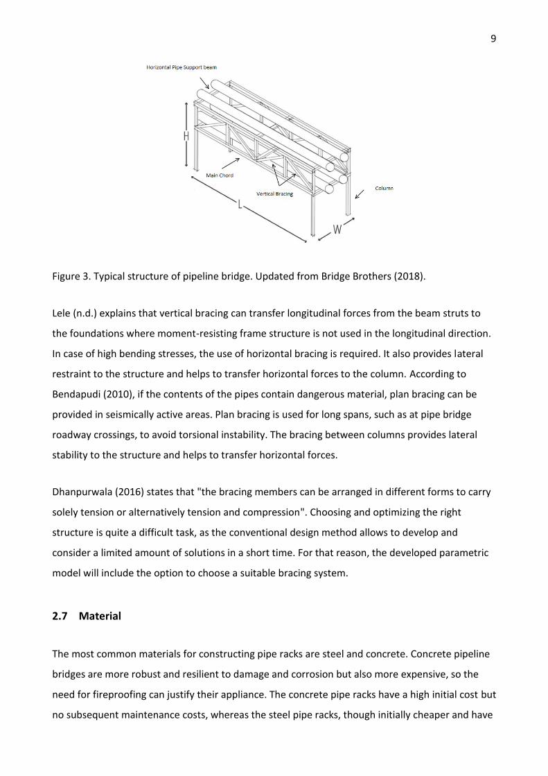
2.6 Structural elements of a pipeline bridge
The structure of the pipe bridge adapts to the requirements of the project but consistently
maintains repetitive shape and, in the case of conventional systems, consists of the following
elements: columns, transverse beams (supports for piping), longitudinal struts (main chords), and
a bracing system. The principal elements of the pipeline bridge structure are illustrated in Figure 3.
A general rule for designing a pipeline support system is to consider it as a rigid frame in a
transverse direction and as braced in longitudinal (El-Reedy, 2017). The pipe rack's structural
elements must be able to withstand axial loads, shears, and moments.
9
Figure 3. Typical structure of pipeline bridge. Updated from Bridge Brothers (2018).
Lele (n.d.) explains that vertical bracing can transfer longitudinal forces from the beam struts to
the foundations where moment-resisting frame structure is not used in the longitudinal direction.
In case of high bending stresses, the use of horizontal bracing is required. It also provides lateral
restraint to the structure and helps to transfer horizontal forces to the column. According to
Bendapudi (2010), if the contents of the pipes contain dangerous material, plan bracing can be
provided in seismically active areas. Plan bracing is used for long spans, such as at pipe bridge
roadway crossings, to avoid torsional instability. The bracing between columns provides lateral
stability to the structure and helps to transfer horizontal forces.
Dhanpurwala (2016) states that "the bracing members can be arranged in different forms to carry
solely tension or alternatively tension and compression". Choosing and optimizing the right
structure is quite a difficult task, as the conventional design method allows to develop and
consider a limited amount of solutions in a short time. For that reason, the developed parametric
model will include the option to choose a suitable bracing system.
2.7 Material
The most common materials for constructing pipe racks are steel and concrete. Concrete pipeline
bridges are more robust and resilient to damage and corrosion but also more expensive, so the
need for fireproofing can justify their appliance. The concrete pipe racks have a high initial cost but
no subsequent maintenance costs, whereas the steel pipe racks, though initially cheaper and have
10
lesser construction time, require regular coat painting due to corrosion, especially in coastal areas.
In this thesis, only steel pipe bridges were considered. Rathdore (2016) claims that steel pipe racks
better for fast construction and it is a better option when construction time is limited by tight
deadlines.
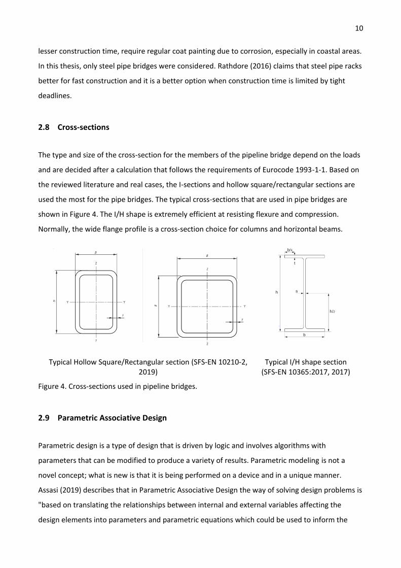
2.8 Cross-sections
The type and size of the cross-section for the members of the pipeline bridge depend on the loads
and are decided after a calculation that follows the requirements of Eurocode 1993-1-1. Based on
the reviewed literature and real cases, the I-sections and hollow square/rectangular sections are
used the most for the pipe bridges. The typical cross-sections that are used in pipe bridges are
shown in Figure 4. The I/H shape is extremely efficient at resisting flexure and compression.
Normally, the wide flange profile is a cross-section choice for columns and horizontal beams.
Typical Hollow Square/Rectangular section (SFS-EN 10210-2, 2019)
Typical I/H shape section (SFS-EN 10365:2017, 2017)
Figure 4. Cross-sections used in pipeline bridges.
2.9 Parametric Associative Design
Parametric design is a type of design that is driven by logic and involves algorithms with
parameters that can be modified to produce a variety of results. Parametric modeling is not a
novel concept; what is new is that it is being performed on a device and in a unique manner.
Assasi (2019) describes that in Parametric Associative Design the way of solving design problems is
"based on translating the relationships between internal and external variables affecting the
design elements into parameters and parametric equations which could be used to inform the
11
design of complex systems". It allows controlling the design process more precisely; it is excellent
for remodeling structures and accuracy for digital fabrication.
In this design method, a huge amount of data and calculations are processed through the flow of
algorithms. The design of complex objects consists of a layering of levels and forms with different
hierarchies, each associated with its own logic and details. These levels are all intertwined, and
their components affect one another, which is why this approach is referred to as "associative."
(Khabazi, 2010) The endpoint of one curve created by the associative method might be the middle
point of another circle, and any change in the curve would cause the circle to change as well. The
main point of it is that all of the created geometries are easily adjustable. Designers have constant
access to all aspects of the design product, from the beginning to the end. The algorithm's inputs
may be altered, and the result may also be revised since the design product is the outcome of an
algorithm. By modifying simple geometrical parameters, it is now possible to digitally draw a
model and create hundreds of project variations. Material characteristics, fabrication constraints,
and assembly logic may all be embedded in parameters.
2.9.1 Potential of parametric modeling in construction engineering
The use of parametric modeling for the creation of complex structures with unusual geometry is
widely known. However, the possibilities of parametric modeling in the construction sector are not
limited to this. Many structures have repeating geometry that can be automated with the right
approach.
Unlike traditional CAD software which is merely based on geometric objects that every single
change needs to modify all appropriate components in order to fix the design, parametric design
tools can make associations between geometrics and operations as well as link them together and
with others via explicit or implicit stated relationships (Kalsi, 2015).
The parametric modeling process has tremendous potential to save time and resources, as it is
allowed to automate modifications in the model. The first step towards optimization is the
efficient calculation of different configurations, which is possible using parametric associative
geometry models (Ledermann et al., 2005). Most software that supports parametric modeling
tools also supports smooth compatibility with other conventional software.
12
Some software programs already adapted the basics of parametric modeling enabling control of
modifying properties of a bunch of elements by adding a single variable. Specialized software like
Grasshopper may establish relationships between project parameters, allowing one to alter in
response to alterations in others.
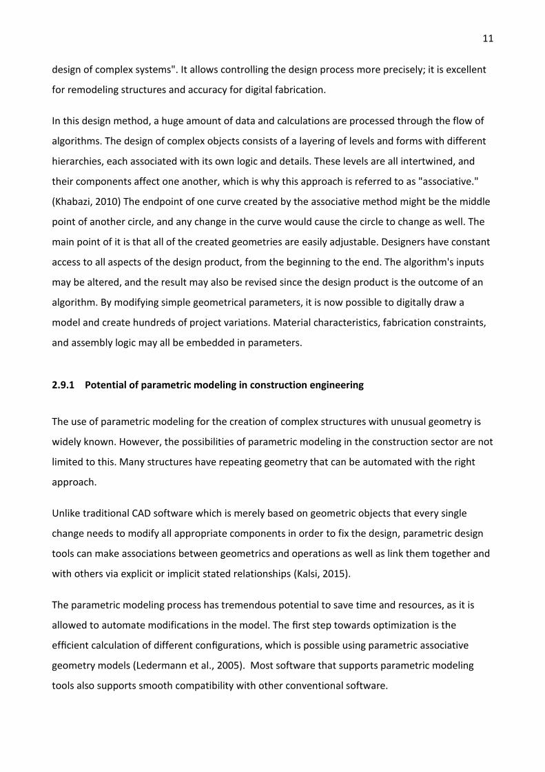
3 METHODS
In this thesis, the method comprises a design concept and a developed algorithm. The design
concept is based on the information described in the knowledge base part, while the developed
algorithm was embodied based on the concept idea by utilizing parametric software capabilities.
Figure 5 illustrates a modeling process used in the thesis.
Figure 5. Work approach for creating a parametric model.
First, literature sources about the design process of pipeline bridges were obtained and studied.
Further, in order to understand the principles of parametric thinking, various materials related to
the topic and guides to parametric software were studied. The concept that employs obtained
data was formulated and a parametric model of the pipe rack was developed. The model was
tested and then presented in the thesis.
4 SOFTWARE
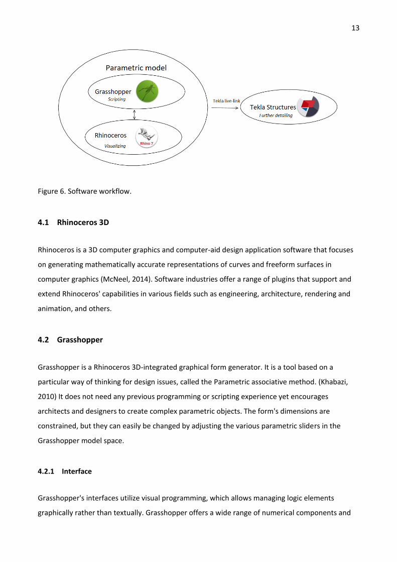
In this thesis, mainly three software were used in a linked workflow, as seen in Figure 6. The
geometry was created by visual programming in the Grasshopper environment and was visualized
in Rhino 7. Although the script used none of the Rhino 7 functions, this software still needs to be
mentioned since Grasshopper is integrated into it. The export of the model's geometry to the
Tekla was done through Grasshopper's plugin called Tekla live-link. The exported model in Tekla
serves for further detailing, documentation and still can be changed by the manipulations in
Grasshoppers script.
Literature review
Software learning
Creation of algorithm
Testing Presentation
13
Figure 6. Software workflow.
4.1 Rhinoceros 3D
Rhinoceros is a 3D computer graphics and computer-aid design application software that focuses
on generating mathematically accurate representations of curves and freeform surfaces in
computer graphics (McNeel, 2014). Software industries offer a range of plugins that support and
extend Rhinoceros' capabilities in various fields such as engineering, architecture, rendering and
animation, and others.
4.2 Grasshopper
Grasshopper is a Rhinoceros 3D-integrated graphical form generator. It is a tool based on a
particular way of thinking for design issues, called the Parametric associative method. (Khabazi,
2010) It does not need any previous programming or scripting experience yet encourages
architects and designers to create complex parametric objects. The form's dimensions are
constrained, but they can easily be changed by adjusting the various parametric sliders in the
Grasshopper model space.
4.2.1 Interface
Grasshopper's interfaces utilize visual programming, which allows managing logic elements
graphically rather than textually. Grasshopper offers a wide range of numerical components and
14
functions that allow the creation of different algorithms with similar results depending on the
designer's approach.
Component Panels and Canvas are the two most significant aspects of the Grasshopper interface.
The component panel consists of all design elements, while Canvas is a workspace where
components and algorithms are set up.
There are two types of objects that are used for modeling: parameters and components.
Parameters can be defined as objects that store data. Components are objects that perform
actions based on the input. Components can carry out a wide range of functions. (Payne & Issa,
2009) In general, a variable receives data from one or more sources and returns the output.
Component with input data should relate to the processing component and then link the output to
the other component; it can continue until the desired algorithm's outcome is achieved. As
parameters or geometry are changed, the modifications occur across all functions, and the
geometry is redrawn. All geometry created with the different Grasshopper components will
appear in the Rhino window.
4.3 Tekla live-link
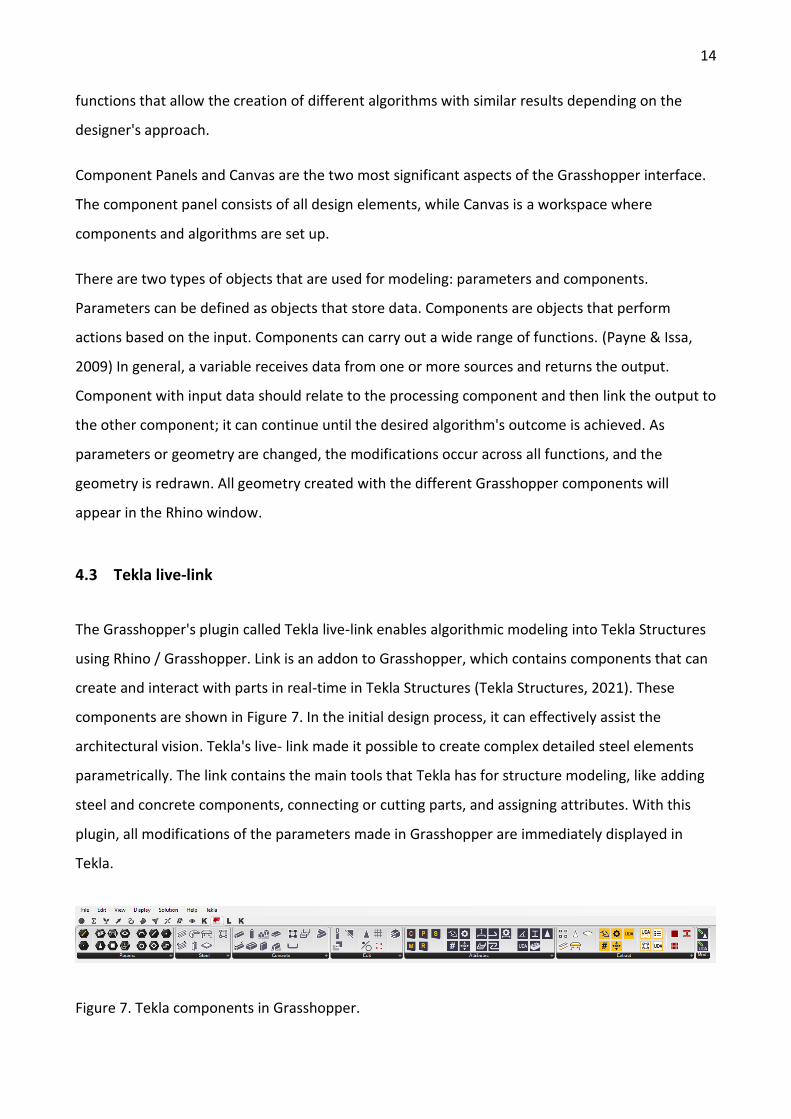
The Grasshopper's plugin called Tekla live-link enables algorithmic modeling into Tekla Structures
using Rhino / Grasshopper. Link is an addon to Grasshopper, which contains components that can
create and interact with parts in real-time in Tekla Structures (Tekla Structures, 2021). These
components are shown in Figure 7. In the initial design process, it can effectively assist the
architectural vision. Tekla's live- link made it possible to create complex detailed steel elements
parametrically. The link contains the main tools that Tekla has for structure modeling, like adding
steel and concrete components, connecting or cutting parts, and assigning attributes. With this
plugin, all modifications of the parameters made in Grasshopper are immediately displayed in
Tekla.
Figure 7. Tekla components in Grasshopper.
15
4.4 Tekla BIM
Tekla Structures is already a powerful BIM tool for structure modeling that enables managing
projects from an idea to the fabrication stage. It suggests versatile design solutions but still has
room for improvements. The article about parametric modeling in Tekla Structure Blog (n.d)
accurately points out that structural models created as a result of integration between
Grasshopper and Tekla "can be used throughout the project lifecycle from managing changes and
avoiding errors to finding clashes and producing better quality structures with less waste, all the
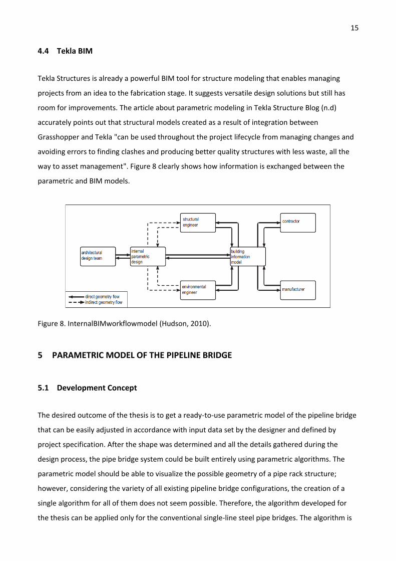
way to asset management". Figure 8 clearly shows how information is exchanged between the
parametric and BIM models.
Figure 8. InternalBIMworkflowmodel (Hudson, 2010).
5 PARAMETRIC MODEL OF THE PIPELINE BRIDGE
5.1 Development Concept
The desired outcome of the thesis is to get a ready-to-use parametric model of the pipeline bridge
that can be easily adjusted in accordance with input data set by the designer and defined by
project specification. After the shape was determined and all the details gathered during the
design process, the pipe bridge system could be built entirely using parametric algorithms. The
parametric model should be able to visualize the possible geometry of a pipe rack structure;
however, considering the variety of all existing pipeline bridge configurations, the creation of a
single algorithm for all of them does not seem possible. Therefore, the algorithm developed for
the thesis can be applied only for the conventional single-line steel pipe bridges. The algorithm is
16
created based on the data obtained during research in the Grasshopper environment, with
components from the Tekla live-link plugin. The created geometry automatically shows on the
Tekla model, with the selected cross-sections and material, and all changes made in Grasshopper
are simultaneously displayed in the Tekla as well. Previously, the typical structure of the pipeline
bridge was described in the thesis.
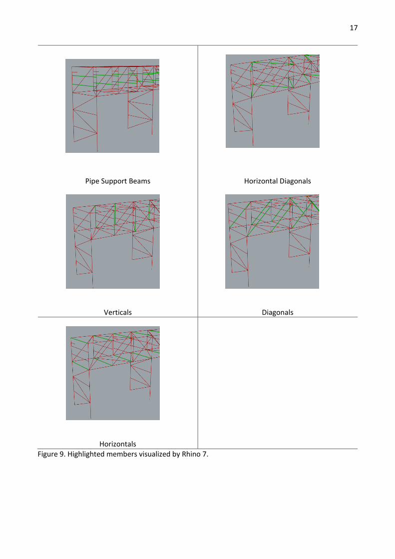
5.2 Parameters
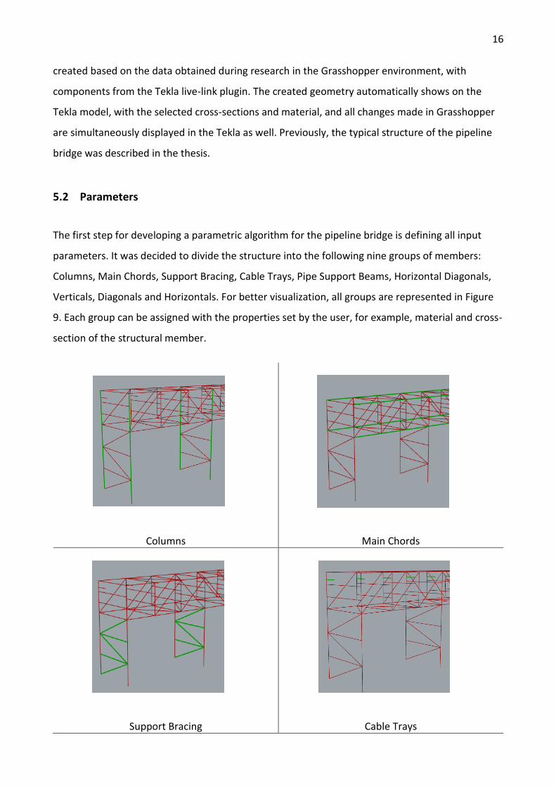
The first step for developing a parametric algorithm for the pipeline bridge is defining all input
parameters. It was decided to divide the structure into the following nine groups of members:
Columns, Main Chords, Support Bracing, Cable Trays, Pipe Support Beams, Horizontal Diagonals,
Verticals, Diagonals and Horizontals. For better visualization, all groups are represented in Figure
9. Each group can be assigned with the properties set by the user, for example, material and cross-
section of the structural member.
Columns Main Chords
Support Bracing Cable Trays
17
Pipe Support Beams Horizontal Diagonals
Verticals Diagonals
Horizontals
Figure 9. Highlighted members visualized by Rhino 7.
18
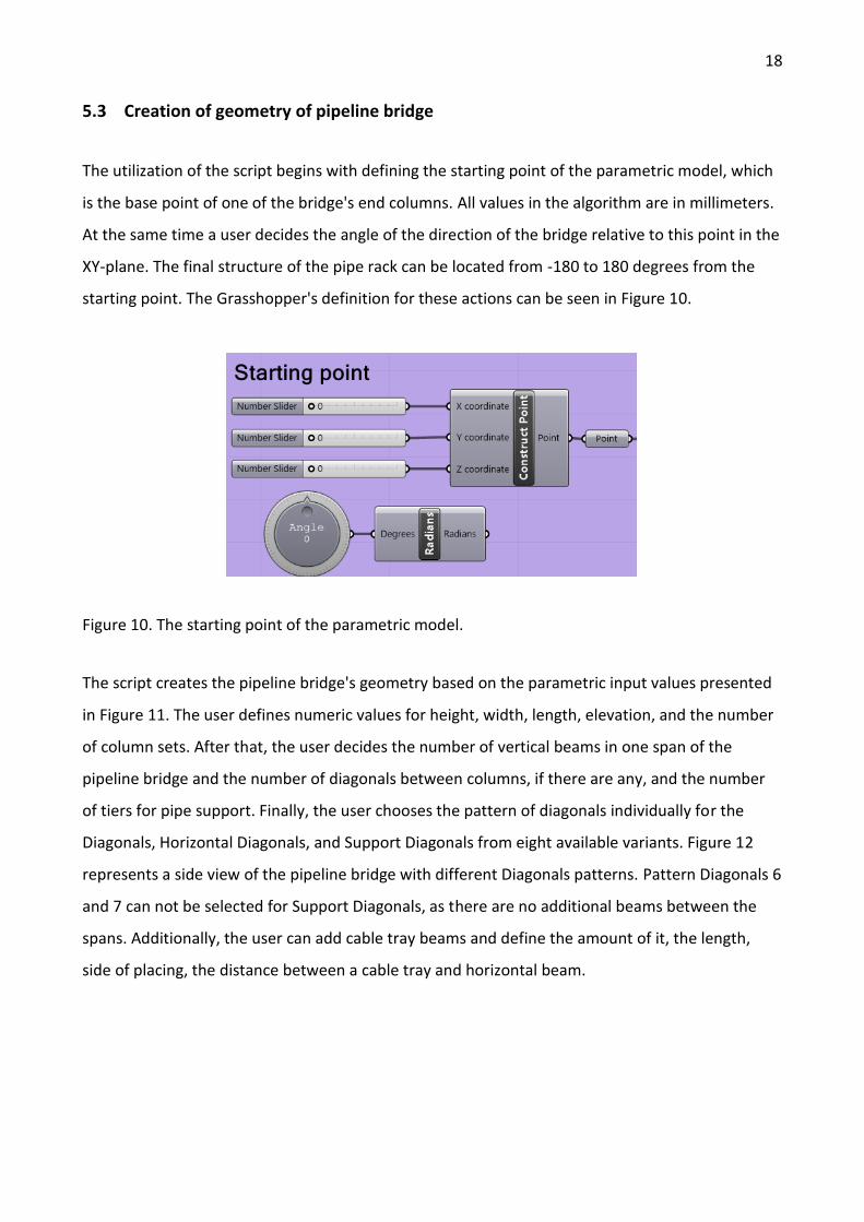
5.3 Creation of geometry of pipeline bridge
The utilization of the script begins with defining the starting point of the parametric model, which
is the base point of one of the bridge's end columns. All values in the algorithm are in millimeters.
At the same time a user decides the angle of the direction of the bridge relative to this point in the
XY-plane. The final structure of the pipe rack can be located from -180 to 180 degrees from the
starting point. The Grasshopper's definition for these actions can be seen in Figure 10.
Figure 10. The starting point of the parametric model.
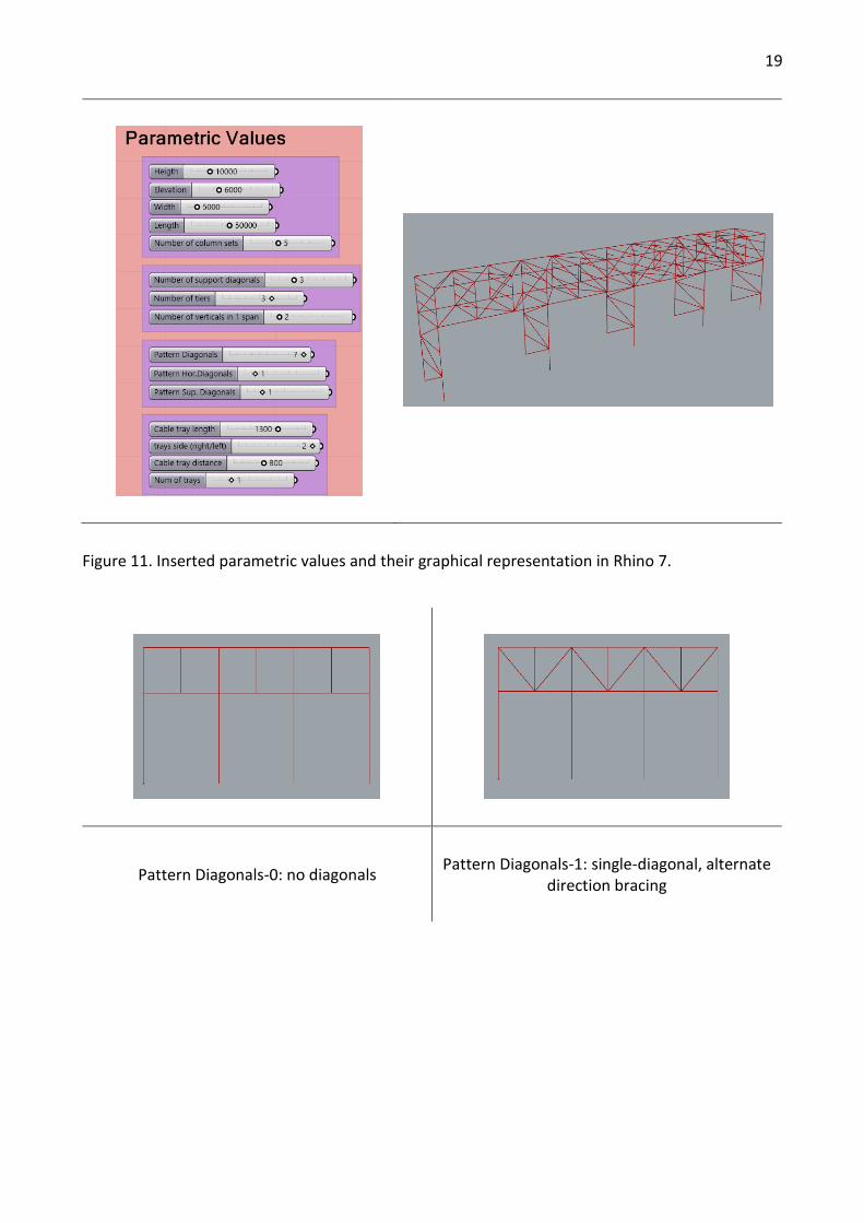
The script creates the pipeline bridge's geometry based on the parametric input values presented
in Figure 11. The user defines numeric values for height, width, length, elevation, and the number
of column sets. After that, the user decides the number of vertical beams in one span of the
pipeline bridge and the number of diagonals between columns, if there are any, and the number
of tiers for pipe support. Finally, the user chooses the pattern of diagonals individually for the
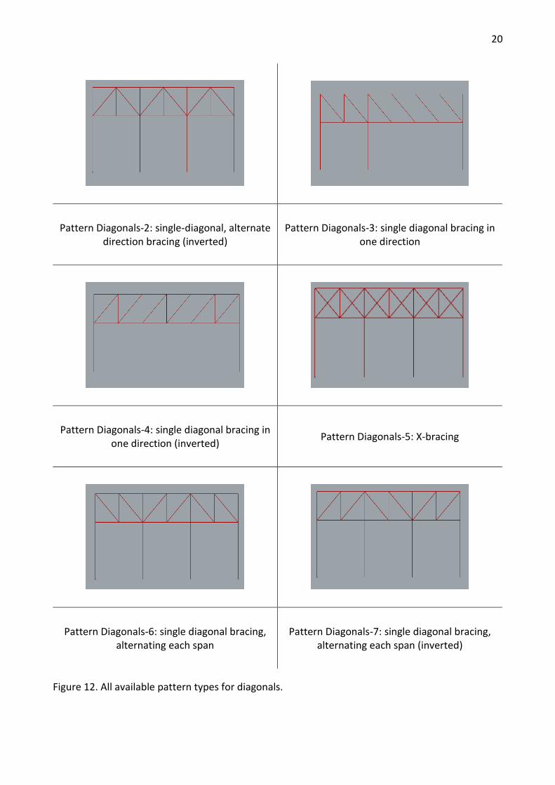
Diagonals, Horizontal Diagonals, and Support Diagonals from eight available variants. Figure 12
represents a side view of the pipeline bridge with different Diagonals patterns. Pattern Diagonals 6
and 7 can not be selected for Support Diagonals, as there are no additional beams between the
spans. Additionally, the user can add cable tray beams and define the amount of it, the length,
side of placing, the distance between a cable tray and horizontal beam.
19
Figure 11. Inserted parametric values and their graphical representation in Rhino 7.
Pattern Diagonals-0: no diagonals Pattern Diagonals-1: single-diagonal, alternate
direction bracing
20
Pattern Diagonals-2: single-diagonal, alternate direction bracing (inverted)
Pattern Diagonals-3: single diagonal bracing in one direction
Pattern Diagonals-4: single diagonal bracing in one direction (inverted)
Pattern Diagonals-5: X-bracing
Pattern Diagonals-6: single diagonal bracing, alternating each span
Pattern Diagonals-7: single diagonal bracing, alternating each span (inverted)
Figure 12. All available pattern types for diagonals.
21
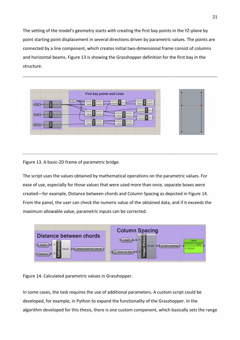
The setting of the model's geometry starts with creating the first bay points in the YZ-plane by
point starting point displacement in several directions driven by parametric values. The points are
connected by a line component, which creates initial two-dimensional frame consist of columns
and horizontal beams. Figure 13 is showing the Grasshopper definition for the first bay in the
structure.
Figure 13. A basic-2D frame of parametric bridge.
The script uses the values obtained by mathematical operations on the parametric values. For
ease of use, especially for those values that were used more than once, separate boxes were
created—for example, Distance between chords and Column Spacing as depicted in Figure 14.
From the panel, the user can check the numeric value of the obtained data, and if it exceeds the
maximum allowable value, parametric inputs can be corrected.
Figure 14. Calculated parametric values in Grasshopper.
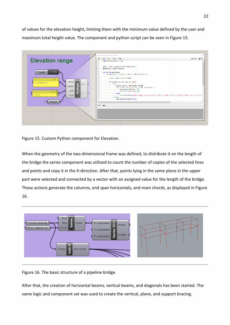
In some cases, the task requires the use of additional parameters. A custom script could be
developed, for example, in Python to expand the functionality of the Grasshopper. In the
algorithm developed for this thesis, there is one custom component, which basically sets the range
22
of values for the elevation height, limiting them with the minimum value defined by the user and
maximum total height value. The component and python script can be seen in Figure 15.
Figure 15. Custom Python component for Elevation.
When the geometry of the two-dimensional frame was defined, to distribute it on the length of
the bridge the series component was utilized to count the number of copies of the selected lines
and points and copy it in the X-direction. After that, points lying in the same plane in the upper
part were selected and connected by a vector with an assigned value for the length of the bridge.
These actions generate the columns, end span horizontals, and main chords, as displayed in Figure
16.
Figure 16. The basic structure of a pipeline bridge.
After that, the creation of horizontal beams, vertical beams, and diagonals has been started. The
same logic and component set was used to create the vertical, plane, and support bracing.
23
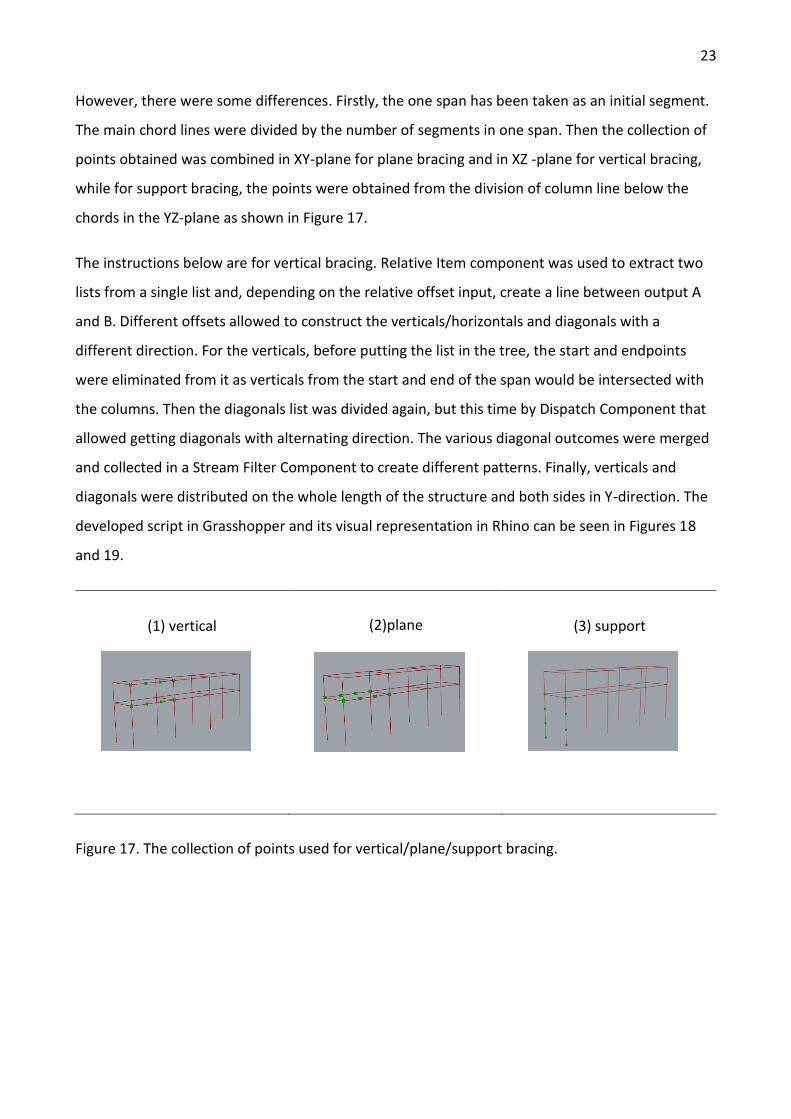
However, there were some differences. Firstly, the one span has been taken as an initial segment.
The main chord lines were divided by the number of segments in one span. Then the collection of
points obtained was combined in XY-plane for plane bracing and in XZ -plane for vertical bracing,
while for support bracing, the points were obtained from the division of column line below the
chords in the YZ-plane as shown in Figure 17.
The instructions below are for vertical bracing. Relative Item component was used to extract two
lists from a single list and, depending on the relative offset input, create a line between output A
and B. Different offsets allowed to construct the verticals/horizontals and diagonals with a
different direction. For the verticals, before putting the list in the tree, the start and endpoints
were eliminated from it as verticals from the start and end of the span would be intersected with
the columns. Then the diagonals list was divided again, but this time by Dispatch Component that
allowed getting diagonals with alternating direction. The various diagonal outcomes were merged
and collected in a Stream Filter Component to create different patterns. Finally, verticals and
diagonals were distributed on the whole length of the structure and both sides in Y-direction. The
developed script in Grasshopper and its visual representation in Rhino can be seen in Figures 18
and 19.
(1) vertical
(2)plane
(3) support
Figure 17. The collection of points used for vertical/plane/support bracing.
24
Figure 18. The Grasshopper script for vertical bracing.
Figure 19. The created vertical bracing with pattern type 2.
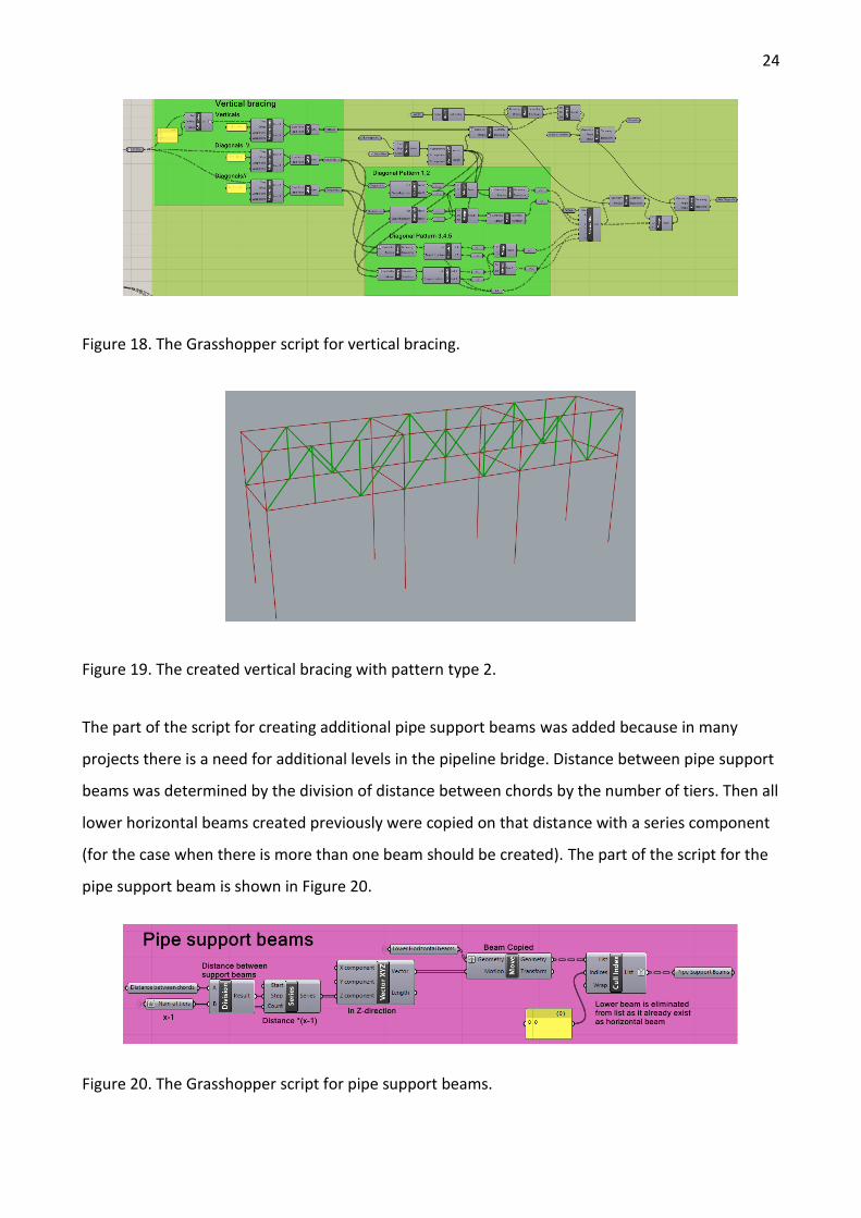
The part of the script for creating additional pipe support beams was added because in many
projects there is a need for additional levels in the pipeline bridge. Distance between pipe support
beams was determined by the division of distance between chords by the number of tiers. Then all
lower horizontal beams created previously were copied on that distance with a series component
(for the case when there is more than one beam should be created). The part of the script for the
pipe support beam is shown in Figure 20.
Figure 20. The Grasshopper script for pipe support beams.
25
The cable trays were created by adding series of lines with a certain length on the given distance
from upper horizontal beams, distributed on the whole length of the bridge with the step equal
length of one segment in the span.
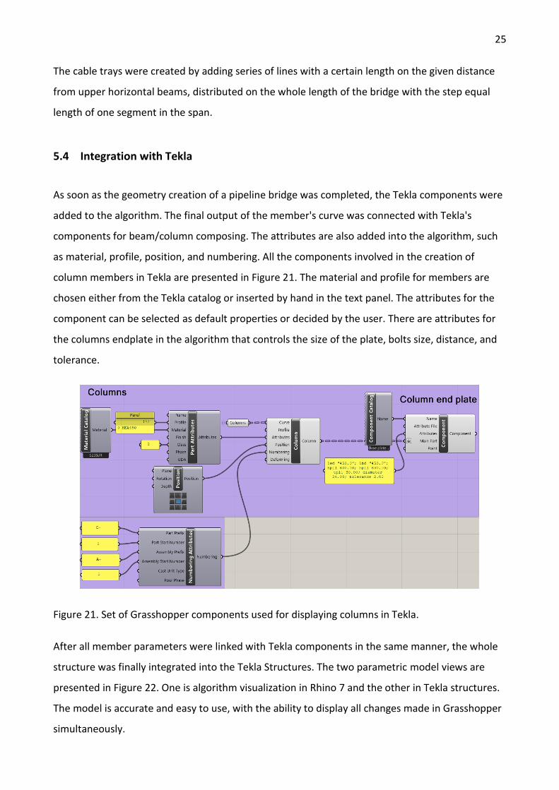
5.4 Integration with Tekla
As soon as the geometry creation of a pipeline bridge was completed, the Tekla components were
added to the algorithm. The final output of the member's curve was connected with Tekla's
components for beam/column composing. The attributes are also added into the algorithm, such
as material, profile, position, and numbering. All the components involved in the creation of
column members in Tekla are presented in Figure 21. The material and profile for members are
chosen either from the Tekla catalog or inserted by hand in the text panel. The attributes for the
component can be selected as default properties or decided by the user. There are attributes for
the columns endplate in the algorithm that controls the size of the plate, bolts size, distance, and
tolerance.
Figure 21. Set of Grasshopper components used for displaying columns in Tekla.
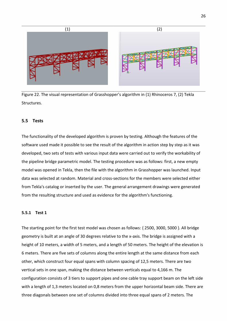
After all member parameters were linked with Tekla components in the same manner, the whole
structure was finally integrated into the Tekla Structures. The two parametric model views are
presented in Figure 22. One is algorithm visualization in Rhino 7 and the other in Tekla structures.
The model is accurate and easy to use, with the ability to display all changes made in Grasshopper
simultaneously.
26
(1)
(2)
Figure 22. The visual representation of Grasshopper’s algorithm in (1) Rhinoceros 7, (2) Tekla
Structures.
5.5 Tests
The functionality of the developed algorithm is proven by testing. Although the features of the
software used made it possible to see the result of the algorithm in action step by step as it was
developed, two sets of tests with various input data were carried out to verify the workability of
the pipeline bridge parametric model. The testing procedure was as follows: first, a new empty
model was opened in Tekla, then the file with the algorithm in Grasshopper was launched. Input
data was selected at random. Material and cross-sections for the members were selected either
from Tekla's catalog or inserted by the user. The general arrangement drawings were generated
from the resulting structure and used as evidence for the algorithm's functioning.
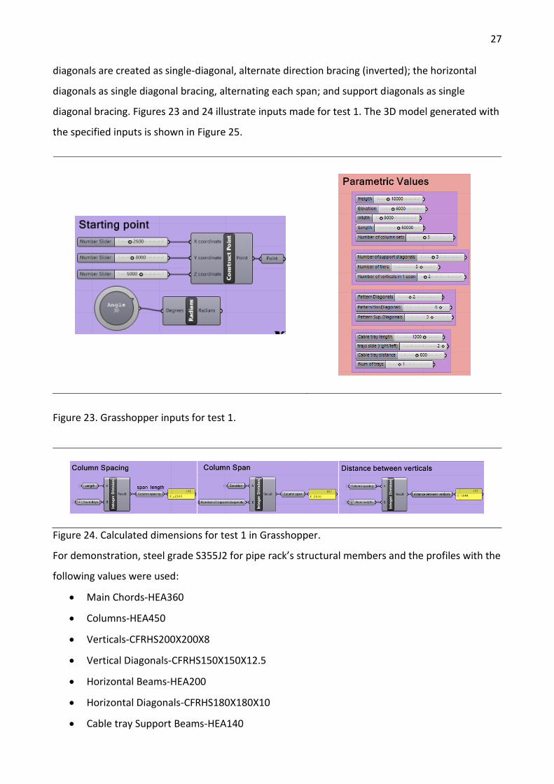
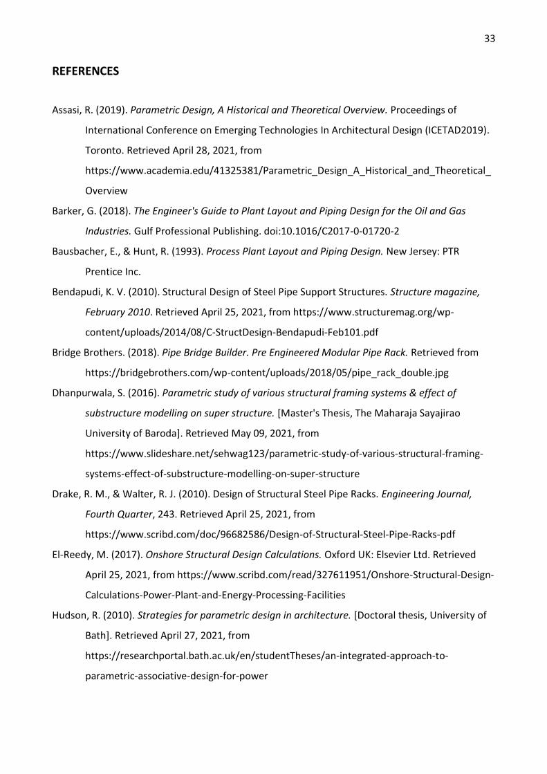
5.5.1 Test 1
The starting point for the first test model was chosen as follows: { 2500, 3000, 5000 }. All bridge
geometry is built at an angle of 30 degrees relative to the x-axis. The bridge is assigned with a
height of 10 meters, a width of 5 meters, and a length of 50 meters. The height of the elevation is
6 meters. There are five sets of columns along the entire length at the same distance from each
other, which construct four equal spans with column spacing of 12,5 meters. There are two
vertical sets in one span, making the distance between verticals equal to 4,166 m. The
configuration consists of 3 tiers to support pipes and one cable tray support beam on the left side
with a length of 1,3 meters located on 0,8 meters from the upper horizontal beam side. There are
three diagonals between one set of columns divided into three equal spans of 2 meters. The
27
diagonals are created as single-diagonal, alternate direction bracing (inverted); the horizontal
diagonals as single diagonal bracing, alternating each span; and support diagonals as single
diagonal bracing. Figures 23 and 24 illustrate inputs made for test 1. The 3D model generated with
the specified inputs is shown in Figure 25.
Figure 23. Grasshopper inputs for test 1.
Figure 24. Calculated dimensions for test 1 in Grasshopper.
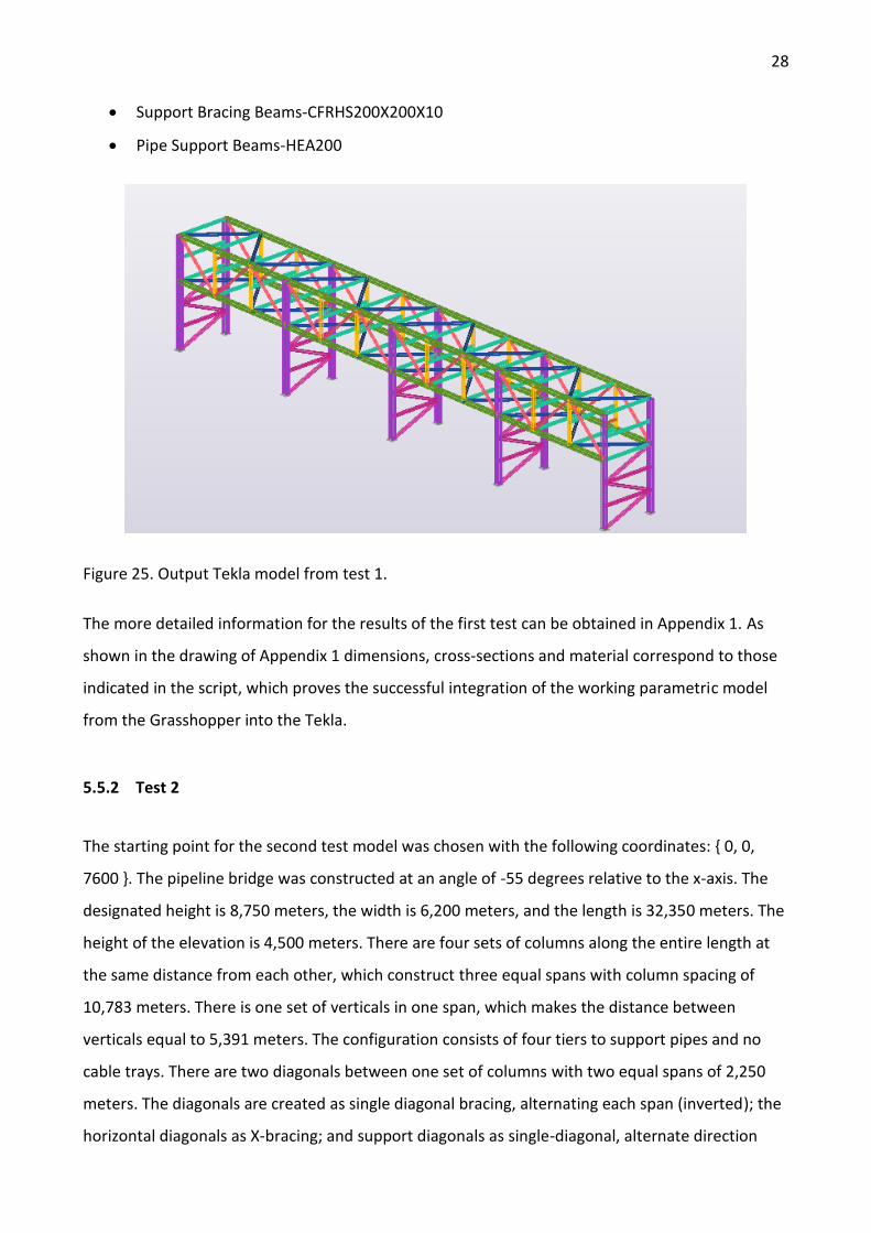
For demonstration, steel grade S355J2 for pipe rack’s structural members and the profiles with the
following values were used:
• Main Chords-HEA360
• Columns-HEA450
• Verticals-CFRHS200X200X8
• Vertical Diagonals-CFRHS150X150X12.5
• Horizontal Beams-HEA200
• Horizontal Diagonals-CFRHS180X180X10
• Cable tray Support Beams-HEA140
28
• Support Bracing Beams-CFRHS200X200X10
• Pipe Support Beams-HEA200
Figure 25. Output Tekla model from test 1.
The more detailed information for the results of the first test can be obtained in Appendix 1. As
shown in the drawing of Appendix 1 dimensions, сross-sections and material correspond to those
indicated in the script, which proves the successful integration of the working parametric model
from the Grasshopper into the Tekla.
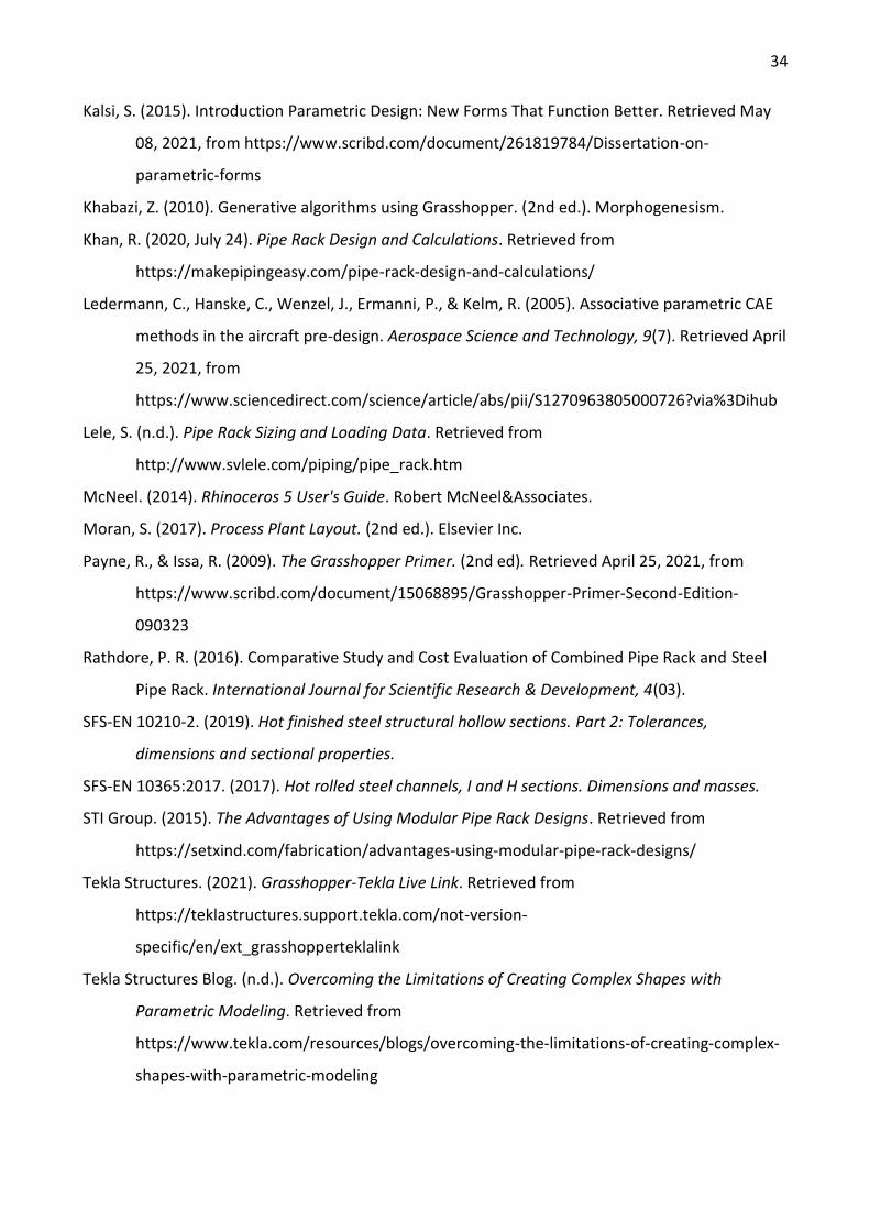
5.5.2 Test 2
The starting point for the second test model was chosen with the following coordinates: { 0, 0,
7600 }. The pipeline bridge was constructed at an angle of -55 degrees relative to the x-axis. The
designated height is 8,750 meters, the width is 6,200 meters, and the length is 32,350 meters. The
height of the elevation is 4,500 meters. There are four sets of columns along the entire length at
the same distance from each other, which construct three equal spans with column spacing of
10,783 meters. There is one set of verticals in one span, which makes the distance between
verticals equal to 5,391 meters. The configuration consists of four tiers to support pipes and no
cable trays. There are two diagonals between one set of columns with two equal spans of 2,250
meters. The diagonals are created as single diagonal bracing, alternating each span (inverted); the
horizontal diagonals as X-bracing; and support diagonals as single-diagonal, alternate direction
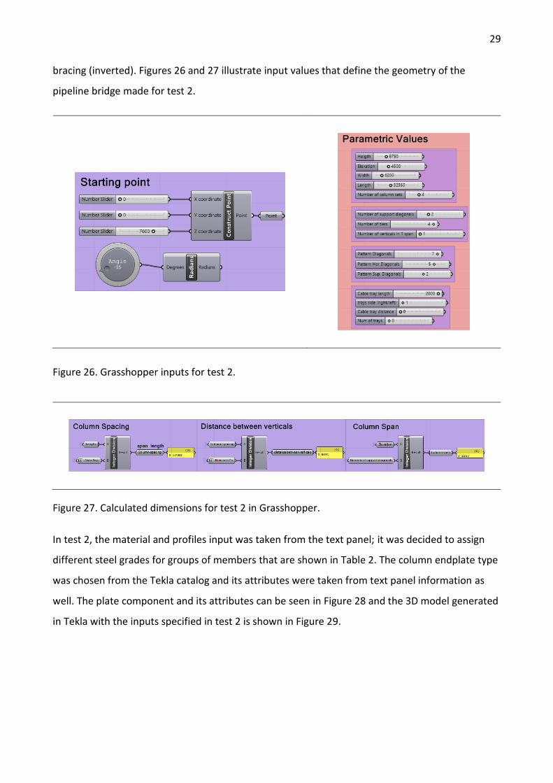
29
bracing (inverted). Figures 26 and 27 illustrate input values that define the geometry of the
pipeline bridge made for test 2.
Figure 26. Grasshopper inputs for test 2.
Figure 27. Calculated dimensions for test 2 in Grasshopper.
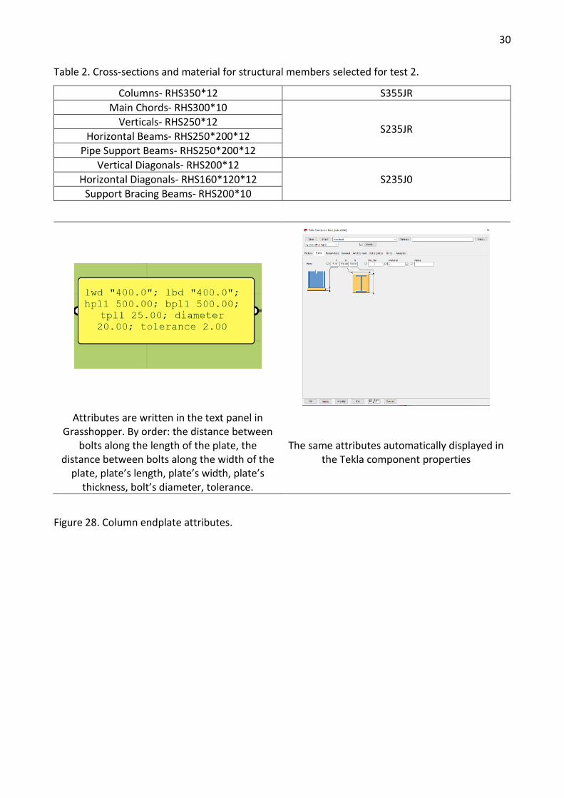
In test 2, the material and profiles input was taken from the text panel; it was decided to assign
different steel grades for groups of members that are shown in Table 2. The column endplate type
was chosen from the Tekla catalog and its attributes were taken from text panel information as
well. The plate component and its attributes can be seen in Figure 28 and the 3D model generated
in Tekla with the inputs specified in test 2 is shown in Figure 29.
30
Table 2. Cross-sections and material for structural members selected for test 2.
Columns- RHS350*12 S355JR
Main Chords- RHS300*10
S235JR Verticals- RHS250*12
Horizontal Beams- RHS250*200*12
Pipe Support Beams- RHS250*200*12
Vertical Diagonals- RHS200*12
S235J0 Horizontal Diagonals- RHS160*120*12
Support Bracing Beams- RHS200*10
Attributes are written in the text panel in
Grasshopper. By order: the distance between bolts along the length of the plate, the
distance between bolts along the width of the plate, plate’s length, plate’s width, plate’s
thickness, bolt’s diameter, tolerance.
The same attributes automatically displayed in the Tekla component properties
Figure 28. Column endplate attributes.
31
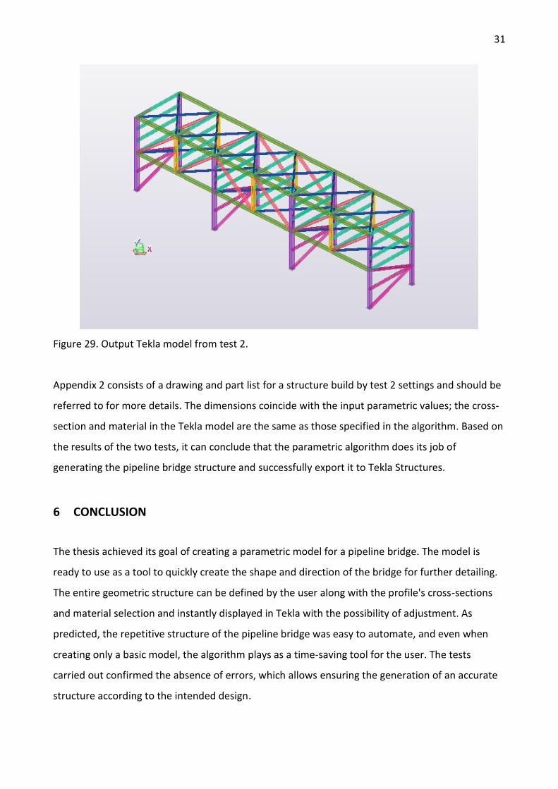
Figure 29. Output Tekla model from test 2.
Appendix 2 consists of a drawing and part list for a structure build by test 2 settings and should be
referred to for more details. The dimensions coincide with the input parametric values; the cross-
section and material in the Tekla model are the same as those specified in the algorithm. Based on
the results of the two tests, it can conclude that the parametric algorithm does its job of
generating the pipeline bridge structure and successfully export it to Tekla Structures.
6 CONCLUSION
The thesis achieved its goal of creating a parametric model for a pipeline bridge. The model is
ready to use as a tool to quickly create the shape and direction of the bridge for further detailing.
The entire geometric structure can be defined by the user along with the profile's cross-sections
and material selection and instantly displayed in Tekla with the possibility of adjustment. As
predicted, the repetitive structure of the pipeline bridge was easy to automate, and even when
creating only a basic model, the algorithm plays as a time-saving tool for the user. The tests
carried out confirmed the absence of errors, which allows ensuring the generation of an accurate
structure according to the intended design.
32
Modeling with a parametric approach is fundamentally different from the conventional methods
for working with pipeline bridges. At the very beginning, the parametric approach may take more
time since it is necessary to process a large amount of information in order to link it in the
algorithm. However, this may make sense in the long term since the more complex and diverse
the model, the more quick and accurate design solutions it can provide. In the case of the
developed algorithm, the user has the opportunity to choose the appropriate type of bracing
following the specified requirements, which means that the model is not limited to one design
solution.
To summarise the above, parametric modeling is an excellent tool for creating design solutions in
a new way; the currently developed model has the potential to be used in the pipeline project,
simultaneously allowing improvement and future development.
6.1 Further use
As it was mentioned before, The Grasshopper algorithm can further be developed into a more
complex and full definition that will also include structural analysis and more versatile options. The
following may constitute the object of future development:
• Including Finite Element Analysis in the script via Karamba (Grasshopper plugin)
• Adding an option to create a pipeline bridge with a non-consistent span length, as in real
life this is usually the case
• Adding more Tekla components to create steel connections
• Enabling more pipeline bridge configurations in the script
33
REFERENCES
Assasi, R. (2019). Parametric Design, A Historical and Theoretical Overview. Proceedings of
International Conference on Emerging Technologies In Architectural Design (ICETAD2019).
Toronto. Retrieved April 28, 2021, from
https://www.academia.edu/41325381/Parametric_Design_A_Historical_and_Theoretical_
Overview
Barker, G. (2018). The Engineer's Guide to Plant Layout and Piping Design for the Oil and Gas
Industries. Gulf Professional Publishing. doi:10.1016/C2017-0-01720-2
Bausbacher, E., & Hunt, R. (1993). Process Plant Layout and Piping Design. New Jersey: PTR
Prentice Inc.
Bendapudi, K. V. (2010). Structural Design of Steel Pipe Support Structures. Structure magazine,
February 2010. Retrieved April 25, 2021, from https://www.structuremag.org/wp-
content/uploads/2014/08/C-StructDesign-Bendapudi-Feb101.pdf
Bridge Brothers. (2018). Pipe Bridge Builder. Pre Engineered Modular Pipe Rack. Retrieved from
https://bridgebrothers.com/wp-content/uploads/2018/05/pipe_rack_double.jpg
Dhanpurwala, S. (2016). Parametric study of various structural framing systems & effect of
substructure modelling on super structure. [Master's Thesis, The Maharaja Sayajirao
University of Baroda]. Retrieved May 09, 2021, from
https://www.slideshare.net/sehwag123/parametric-study-of-various-structural-framing-
systems-effect-of-substructure-modelling-on-super-structure
Drake, R. M., & Walter, R. J. (2010). Design of Structural Steel Pipe Racks. Engineering Journal,
Fourth Quarter, 243. Retrieved April 25, 2021, from
https://www.scribd.com/doc/96682586/Design-of-Structural-Steel-Pipe-Racks-pdf
El-Reedy, M. (2017). Onshore Structural Design Calculations. Oxford UK: Elsevier Ltd. Retrieved
April 25, 2021, from https://www.scribd.com/read/327611951/Onshore-Structural-Design-
Calculations-Power-Plant-and-Energy-Processing-Facilities
Hudson, R. (2010). Strategies for parametric design in architecture. [Doctoral thesis, University of
Bath]. Retrieved April 27, 2021, from
https://researchportal.bath.ac.uk/en/studentTheses/an-integrated-approach-to-
parametric-associative-design-for-power
34
Kalsi, S. (2015). Introduction Parametric Design: New Forms That Function Better. Retrieved May
08, 2021, from https://www.scribd.com/document/261819784/Dissertation-on-
parametric-forms
Khabazi, Z. (2010). Generative algorithms using Grasshopper. (2nd ed.). Morphogenesism.
Khan, R. (2020, July 24). Pipe Rack Design and Calculations. Retrieved from
https://makepipingeasy.com/pipe-rack-design-and-calculations/
Ledermann, C., Hanske, C., Wenzel, J., Ermanni, P., & Kelm, R. (2005). Associative parametric CAE
methods in the aircraft pre-design. Aerospace Science and Technology, 9(7). Retrieved April
25, 2021, from
https://www.sciencedirect.com/science/article/abs/pii/S1270963805000726?via%3Dihub
Lele, S. (n.d.). Pipe Rack Sizing and Loading Data. Retrieved from
http://www.svlele.com/piping/pipe_rack.htm
McNeel. (2014). Rhinoceros 5 User's Guide. Robert McNeel&Associates.
Moran, S. (2017). Process Plant Layout. (2nd ed.). Elsevier Inc.
Payne, R., & Issa, R. (2009). The Grasshopper Primer. (2nd ed). Retrieved April 25, 2021, from
https://www.scribd.com/document/15068895/Grasshopper-Primer-Second-Edition-
090323
Rathdore, P. R. (2016). Comparative Study and Cost Evaluation of Combined Pipe Rack and Steel
Pipe Rack. International Journal for Scientific Research & Development, 4(03).
SFS-EN 10210-2. (2019). Hot finished steel structural hollow sections. Part 2: Tolerances,
dimensions and sectional properties.
SFS-EN 10365:2017. (2017). Hot rolled steel channels, I and H sections. Dimensions and masses.
STI Group. (2015). The Advantages of Using Modular Pipe Rack Designs. Retrieved from
https://setxind.com/fabrication/advantages-using-modular-pipe-rack-designs/
Tekla Structures. (2021). Grasshopper-Tekla Live Link. Retrieved from
https://teklastructures.support.tekla.com/not-version-
specific/en/ext_grasshopperteklalink
Tekla Structures Blog. (n.d.). Overcoming the Limitations of Creating Complex Shapes with
Parametric Modeling. Retrieved from
https://www.tekla.com/resources/blogs/overcoming-the-limitations-of-creating-complex-
shapes-with-parametric-modeling
Appendix 1 / 1
Appendix 1: Documentation for Test 1
Drawing

Appendix 1 / 2
Part List Table
PartPos Profile No. Material Length (mm) Net Area(m2) for one Net Area(m2) for all Net Weight(kg) for one Net Weight(kg) for all
B-/1 CFRHS180X*** 24 S355J2 6509 4.41 105.77 329.88 8338.22
B-/2 CFRHS150X*** 24 S355J2 5776 3.10 74.30 281.29 7481.24
B-/3 HEA360 16 S355J2 12500 22.93 366.80 1401.23 21430.50
B-/4 CFRHS200X*** 16 S355J2 4000 3.06 49.00 186.02 3086.75
B-/5 HEA140 12 S355J2 1300 1.03 12.39 32.06 369.58
B-/6 CFRHS200X*** 15 S355J2 5385 4.08 61.16 306.76 4819.18
B-/7 HEA200 16 S355J2 5000 5.68 90.88 211.28 3205.94
B-/8 CFRHS200X*** 10 S355J2 5000 3.79 37.85 284.82 2983.00
B-/9 HEA200 32 S355J2 5000 5.68 181.76 211.28 6411.88
C-/1 HEA450 10 S355J2 9970 20.05 200.50 1393.11 13443.49
Total for 175 members 1180.41 72417.59
Appendix 2 / 1
Appendix 2: Documentation for Test 2
Drawing

Appendix 2 / 2
Part List Table
PartPos Profile No. Material Length (mm) Net Area(m2) for one Net Area(m2) for all Net Weight(kg) for one Net Weight(kg) for all
1001 PL25*500 8 S235JR 500 0.55 4.40 49.06 392.50
B-/1 RHS300*10 12 S235J0 10783 12.95 155.42 981.90 11782.80
B-/2 RHS200*20*** 12 S235J0 6865 5.50 66.02 486.32 5835.83
B-/3 RHS160*12*** 24 S235J0 8216 4.55 109.31 396.28 9510.66
B-/4 RHS250*20*** 28 S235JR 6200 5.56 155.67 497.60 13932.86
B-/5 RHS250*12 6 S235JR 4250 4.26 25.57 381.13 2286.80
B-/6 RHS200*10 8 S235J0 6596 5.28 42.28 393.50 3147.97
B-/7 RHS200*10 4 S235J0 6200 4.97 19.87 369.89 1479.57
C-/1 RHS350*12 8 S355JR 8725 12.23 97.85 1111.20 8889.62
Total for 110 members 676.39 57258.59


![JCAMECHjournals.ut.ac.ir/article_75013_f161c054d38522a36bd...parametric resonance of a planar fluid-conveying cantilevered pipe. Namachchivaya and Tien [8] on the nonlinear behaviour](https://img.pdfslide.us/doc/110x75/60b08044d6c3842df5181bca/-parametric-resonance-of-a-planar-fluid-conveying-cantilevered-pipe-namachchivaya.jpg)