Embed Size (px)
Citation preview

Draft
Signed online chromatic-dispersion monitoringby synchronous detection of FM-induced
arrival-time modulations in the clock-recoveryphase-locked loop
Reinhold Noé, David Sandel, Suhas Bhandare, Frank Wüst,Biljana Milivojevic, and Vitali Mirvoda
University of Paderborn, EIM-E, Optical Communication and High-Frequency Engineering,Warburger Strasse 100, D-33098 Paderborn, Germany
RECEIVED 28 OCTOBER2003;REVISED 20 MAY 2004;ACCEPTED7 JUNE 2004;PUBLISHED 00 JULY 2004
Chromatic dispersion (CD) in optical single-mode fibers, i.e., the wavelengthdependence of the propagation delay, distorts pulses and is a big problem in10- and 40-Gbit/s transmission systems. Adjustable drop-in CD compensatorsrequire an online CD detection. For this purpose, we modulate the opticalpower of the laser in a 40-Gbit/s transmitter by 1.2% (rms) at a frequencyof 5 MHz. In the presence of CD, the associated periodic optical frequencyvariation modulates the signal arrival time, which is measured by synchronous(lock-in) detection of an error signal in the clock recovery of the receiver. CD aslarge as−268 to+350 ps/nm is detected including its sign, more than by anycomparable technique. The uncertainty of measured arrival-time modulationscan be as low as 100 attoseconds. Moreover, no extra optics or high-frequencyelectronics are needed, which makes this method extremely cheap to implement.Results are given for nonreturn to zero and CSRZ, intensity modulation, anddifferential phase-shift keying. © 2004 Optical Society of America
OCIS codes:060.4510, 060.2270.
1. Introduction
Chromatic dispersion (CD) of existing optical single-mode fiber links is a big obstacle
for the deployment of 10- and 40-Gbit/s transmission equipment.A Even in dispersion- ←compensated long-haul fiber links, the temperature and wavelength dependence of CD maybe problematic. Network operators would therefore like to have adjustable, drop-in CDcompensators. For automatic operation of these, online CD detection is required, includingits sign. Most reported CD detection schemes (e.g., Refs. [1–6]) need extra optical filters,fibers, receivers, and/or high-frequency electronics. Given the strict cost awareness of thetelecommunication industry, these are unlikely to be affordable.
A similar problem, the detection of polarization-mode dispersion, has recently beensolved in a simple manner [7]: The signal parameter that influences the propagation delay,i.e., the state of polarization, was modulated at a low speed. In the receiver, the clock-recovery signals were analyzed to detect the associated arrival-time modulation. Here weapply this principle to CD, for intensity modulation and for differential phase-shift keying(DPSK) [8, 9].
A In Abstract, pls. define CS
© 2004 Optical Society of AmericaJON 3225 August 2004 / Vol. 3, No. 8 / JOURNAL OF OPTICAL NETWORKING 1
Draft
2. Principle
The complex field transfer function of an optical fiber with a lengthL is H (ω) =e− jβ(ω)L, whereω is the optical angular frequency and attenuation has been neglected.It is useful to approximate its phase by a truncated Taylor series,ϕ = −β(ω)L =−
[β+(ω−ω0)β′+(1/2)(ω−ω0)
2 β′′]
L. At ω0, the propagation constantβ(ω) assumes
the valueβ, and its first and second derivatives with respect toω areβ′ andβ′′, respectively.The group delayτg =−ϕ′= [β′+(ω−ω0)β′′]L is a linear function ofω. Its derivative withrespect to wavelengthλ and lengthL is the CD coefficient
D =d2τg
dλdL=−2πc
λ2 β′′,
∼17 ps/(nm·km) in SSMF.B The dimensionless indexγ is defined as ←γ =
DLλ2
T2πc,
(Ref. [10]), whereT is the bit duration. To better understand the effects of CD, consider asmall-signal sinusoidal amplitude modulation with a frequency(ω−ω0)/(2π) = 1/(2T)equal to the Nyquist frequency of a data signal. It is converted into pure phase modulationif there is aπ/2 phase shift of the sidebands with respect to the carrier. This requires(1/2)(ω−ω0)
2 β′′L = ±π/2 or |γ| = 2/π. The values|γ| = 0.252 and|γ| = 0.218 cause1-dB eye-closure penalties in intensity- and DPSK-modulated systems, respectively, for thenonreturn-to-zero (NRZ) signal format [10].
A small pump current modulation of a distributed-feedback (DFB) laser will modu-late the optical power and also the optical frequency. At low frequencies, there can be aconsiderable phase lag between pump current and frequency modulation because the lat-ter depends not only on the carrier density but likewise on the chip temperature, which ismodulated by the pump current with an intrinsic delay. In the presence of CD, a frequencyexcursionδ f causes an arrival time delay of
δτg =−δ fDLλ2
c=−δ f T2γπ.
It can be neglected in comparison with the eye closure as long as|δ f T| � 1, and hence|δτg/T| � |γπ|, holds. In the following, this will be the case. It means that the small-signalmodulation frequency may be chosen so high that it is outside the phase-locked loop (PLL)bandwidth of the clock recovery in the receiver.
3. Chromatic-Dispersion Detection in an Intensity-Modulated System
Figure1 details a transmission setup. 40-Gbit/s data are 16 : 1 multiplexed from 2.5-Gbit/s,223−1 pseudorandom binary sequence (PRBS) data streams with mutual delays of 8 bits.The signal drives a LiNbO3 intensity modulator to modulate the signal of a transmitter laserusing the NRZ modulation format. Alternatively the CSRZ format is used. For this purpose,an additional LiNbO3 intensity modulator between laser and data modulator is driven bya 20-GHz sinusoid, thereby generating∼ 13-ps-long pulses with alternating polarities and40-GHz repetition frequency. A small pump current modulation of the DFB transmitterlaser at 5 MHz results in a 1.2% (rms) amplitude modulation and in an optical frequencymodulation with a 224-MHz (rms) deviation. In the clock and data recovery (CDR, from
BWhat does SSMF stand for?
© 2004 Optical Society of AmericaJON 3225 August 2004 / Vol. 3, No. 8 / JOURNAL OF OPTICAL NETWORKING 2

Draft
Infineon), a clock-phase detector takes the difference of two correlation products, one be-tween the decision circuit output signal and the output signal of an auxiliary decision circuitthat is clockedT/2 later, and a similar one between the decision-circuit output signal cor-responding to the next bit (delayT) and the auxiliary signal. If the clock phase is optimallychosen, each correlation product will on average assume half of its maximum value be-cause the auxiliary decision circuit is clocked exactly in between two subsequent bits. Theclock-phase error signal is fed to a proportional-integral controller (PI). Its output signalcontrols the voltage-controlled oscillator (VCO, from WORK Microwave GmbH). Sincea sinusoidal clock-phase error signal is expected, the controller output signal is likewisesinusoidal, just shifted in phase.
5MHz FM & AM
40Gbit/sdata in
DFB laser
modulationNRZ / CS-RZ
fiber with CD
dataoutCDR
VCO
BPF
BPFAVGCD
phase trimmer & limiter
clock phase error signal (arrival time)
clock signal
refe-rence
PI
photodiode
multiplier
Fig. 1. Experimental setup for chromatic dispersion detection. Fig. 1. Experimental setup for CD detection.
A timing reference is conveniently obtained by detecting the parasitic amplitude mod-ulation. Parasitic amplitude modulation (AM) is contained in a low-frequency copy of thedetected photocurrent. Just like the differentiated arrival time, it is bandpass filtered (BPF).After being amplitude limited, it serves as a reference, with a phase that is adjusted for bestsensitivity. The arrival-time signal is synchronously detected with a multiplier and averaged(AVG). Amplitude and sign of the averaged signal represent the CD. Although Fig.1 ex-plains the principle, signals were in reality processed digitally, and an extra low-frequencyphotodiode was employed to detect the amplitude modulation (AM).
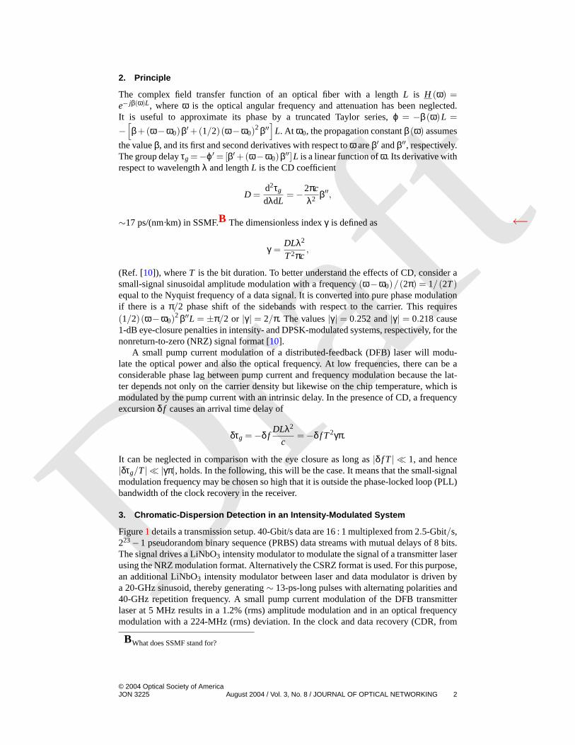
40-Gbit/s data were transmitted with no significant degradation introduced by the laserFM. Bit error rate (BER) measurement failed only when the eye pattern was closed owingto CD. Actual CD values of fibers under test were measured separately using a tunable laserand an oscilloscope triggered from the transmitter side. For NRZ, the usable measurementrange wasDL = −268+ · · ·+ 350 ps/nm. SSMF was used for positive, DSF for nega-tive dispersion. Erbium-doped fiber amplifiers (EDFAs) were added when needed. Figure2 shows Fourier coefficients in the complex plane. Each point represents a measurementinterval of 154µs, and each cloud of points stands for one CD value. The smaller|DL| is,the smaller the standard deviation within a cloud. By synchronous demodulation (lock-indetection), all values are projected along the horizontal axis.
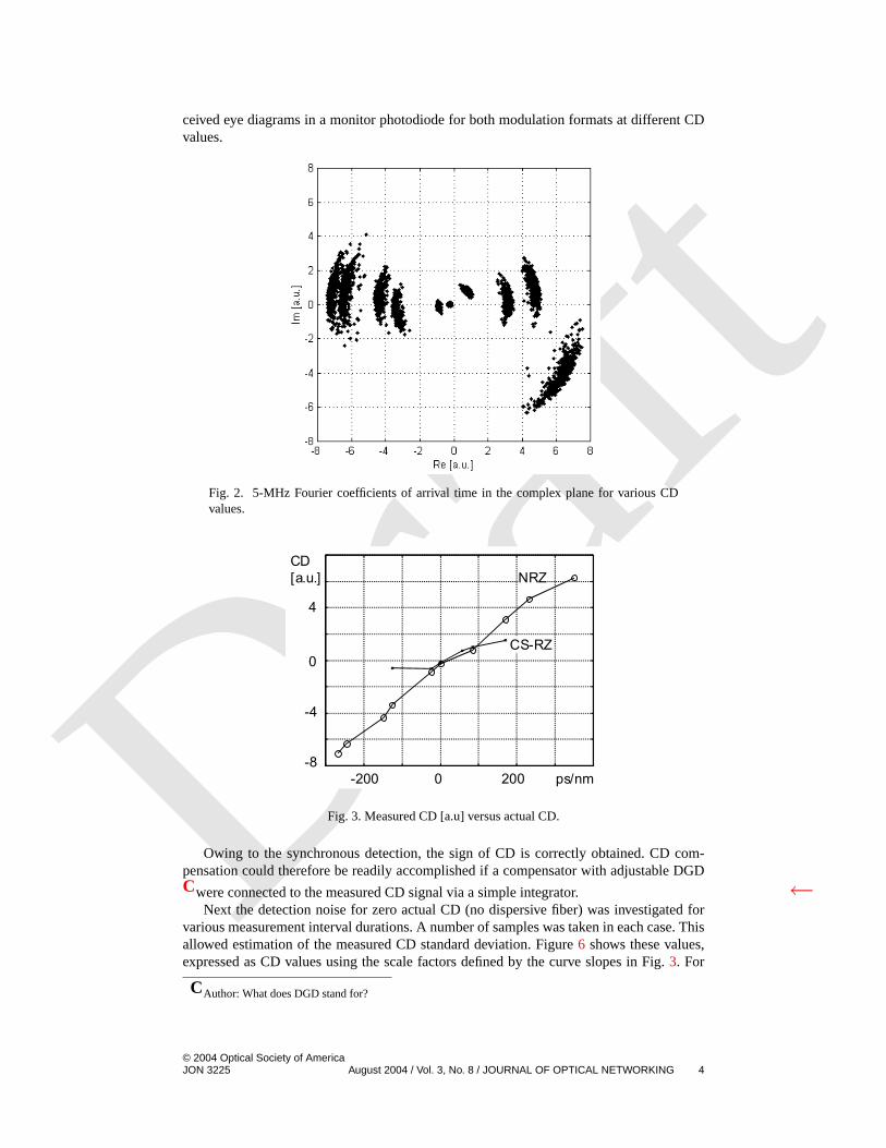
Figure3 shows these CD readings as a function of the actual CD. Not only is the signof CD correctly detected for all cases, but the readout is even monotonous. For largerCD, the clock-recovery PLL failed to lock. The measurement range corresponds toγ =−1.09, . . . ,1.43 for NRZ. To our knowledge, this is the largest signed online CD measure-ment range reported to date. Similar results were obtained for CSRZ but the measurementrange was restricted toDL =−125, . . . ,170 ps/nm (γ =−0.51, . . . ,0.69). However, CSRZis more susceptible to CD than NRZ owing to the shorter pulses. Figures4 and5 show re-
© 2004 Optical Society of AmericaJON 3225 August 2004 / Vol. 3, No. 8 / JOURNAL OF OPTICAL NETWORKING 3
Draft
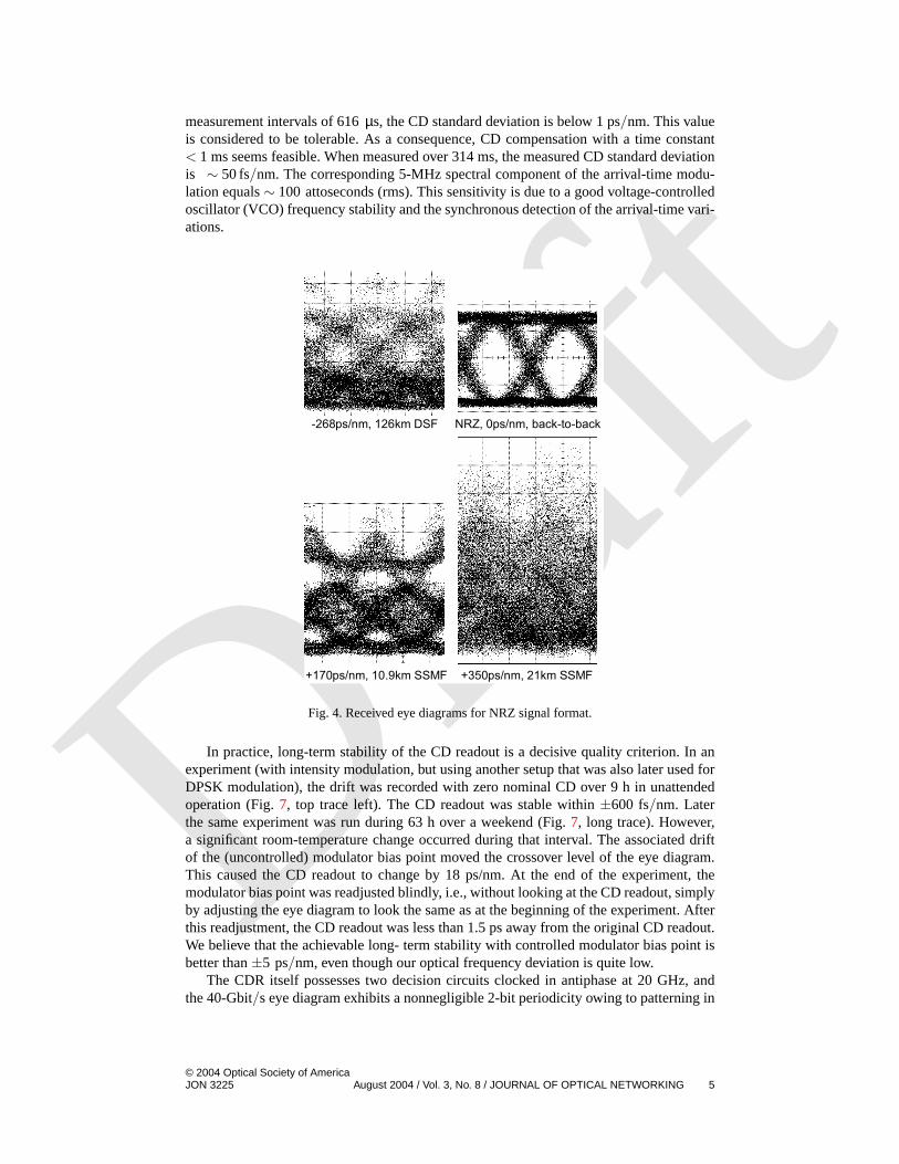
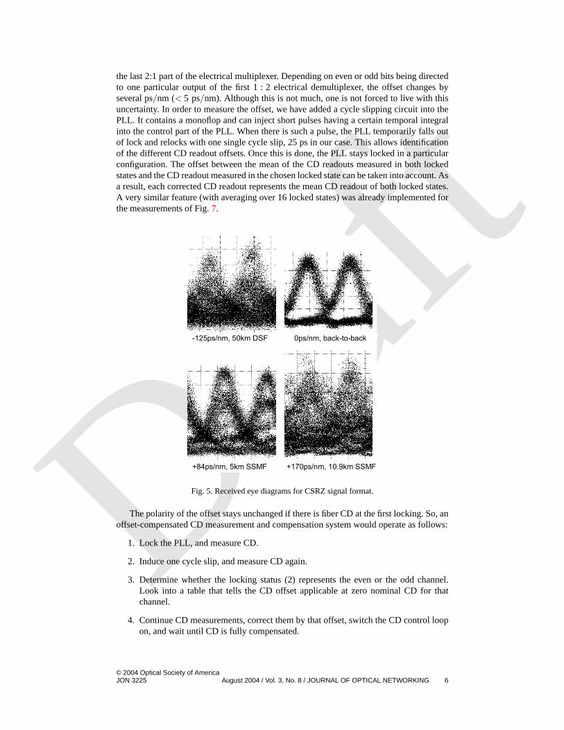
ceived eye diagrams in a monitor photodiode for both modulation formats at different CDvalues.
Fig. 2. 5MHz Fourier coefficients of arrival time in the complex plane for various CD values. Fig. 2. 5-MHz Fourier coefficients of arrival time in the complex plane for various CDvalues.
0 200-200 ps/nm
0
CD[a.u.]
4
-4
-8
NRZ
CS-RZ
Fig. 3. Measured CD [a.u] vs. actual CD. Fig. 3. Measured CD [a.u] versus actual CD.
Owing to the synchronous detection, the sign of CD is correctly obtained. CD com-pensation could therefore be readily accomplished if a compensator with adjustable DGDCwere connected to the measured CD signal via a simple integrator. ←
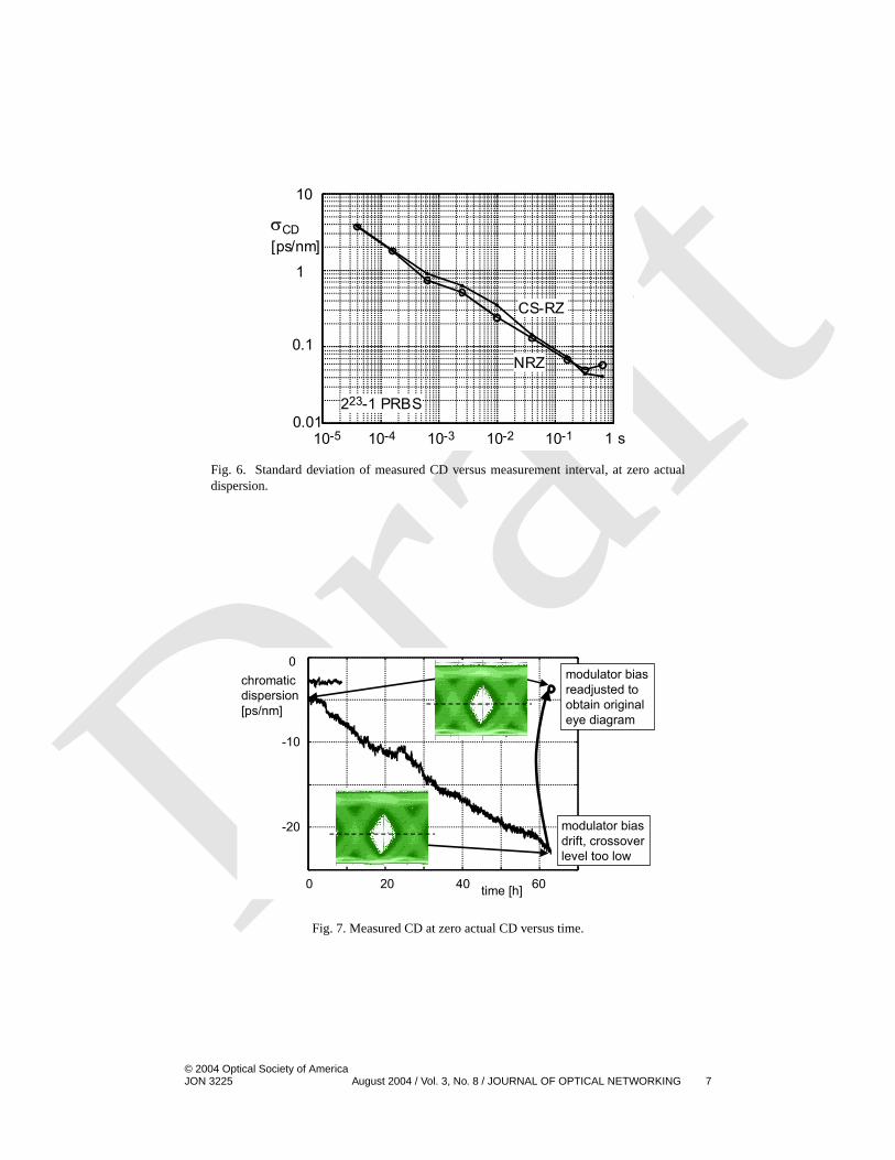
Next the detection noise for zero actual CD (no dispersive fiber) was investigated forvarious measurement interval durations. A number of samples was taken in each case. Thisallowed estimation of the measured CD standard deviation. Figure6 shows these values,expressed as CD values using the scale factors defined by the curve slopes in Fig.3. For
CAuthor: What does DGD stand for?
© 2004 Optical Society of AmericaJON 3225 August 2004 / Vol. 3, No. 8 / JOURNAL OF OPTICAL NETWORKING 4
Draft
measurement intervals of 616µs, the CD standard deviation is below 1 ps/nm. This valueis considered to be tolerable. As a consequence, CD compensation with a time constant< 1 ms seems feasible. When measured over 314 ms, the measured CD standard deviationis ∼ 50 fs/nm. The corresponding 5-MHz spectral component of the arrival-time modu-lation equals∼ 100 attoseconds (rms). This sensitivity is due to a good voltage-controlledoscillator (VCO) frequency stability and the synchronous detection of the arrival-time vari-ations.
+170ps/nm, 10.9km SSMF +350ps/nm, 21km SSMF
-268ps/nm, 126km DSF NRZ, 0ps/nm, back-to-back
Fig. 4. Received eye diagrams for NRZ signal format. Fig. 4. Received eye diagrams for NRZ signal format.
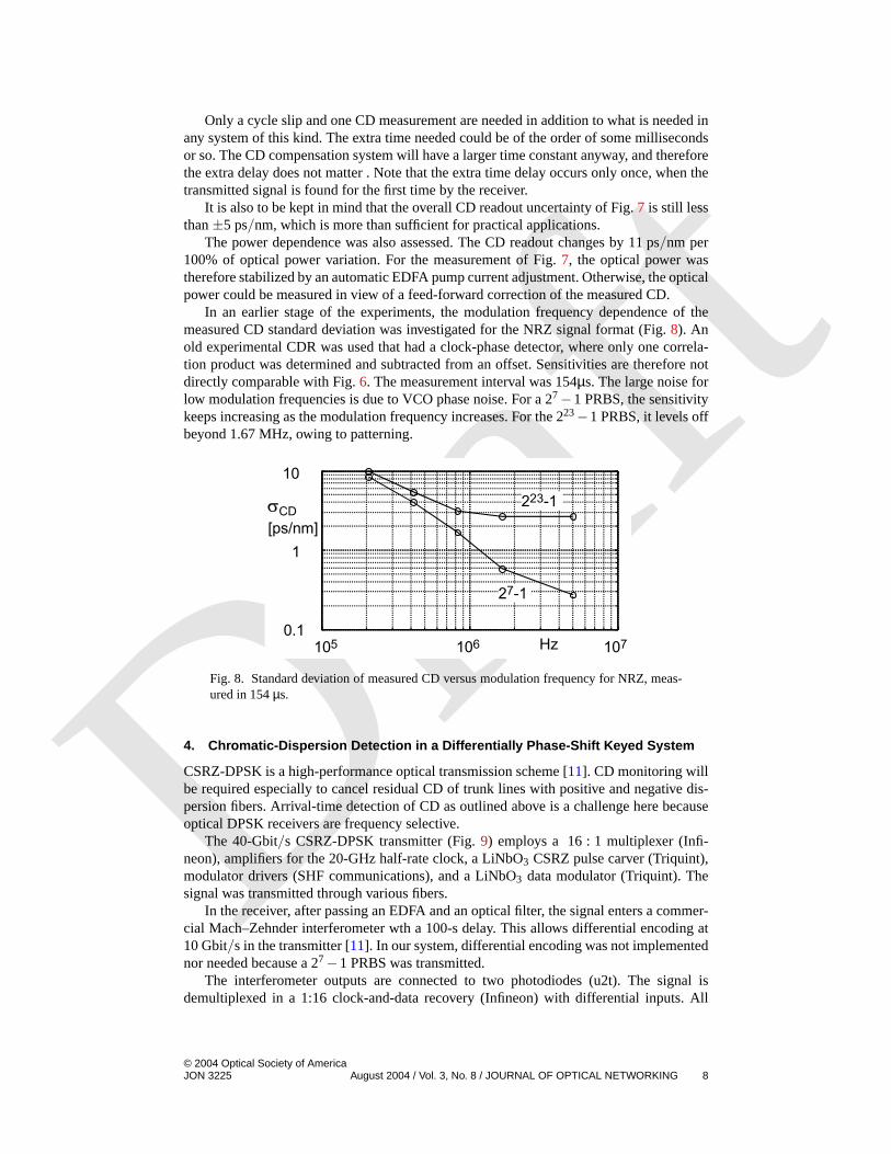
In practice, long-term stability of the CD readout is a decisive quality criterion. In anexperiment (with intensity modulation, but using another setup that was also later used forDPSK modulation), the drift was recorded with zero nominal CD over 9 h in unattendedoperation (Fig.7, top trace left). The CD readout was stable within±600 fs/nm. Laterthe same experiment was run during 63 h over a weekend (Fig.7, long trace). However,a significant room-temperature change occurred during that interval. The associated driftof the (uncontrolled) modulator bias point moved the crossover level of the eye diagram.This caused the CD readout to change by 18 ps/nm. At the end of the experiment, themodulator bias point was readjusted blindly, i.e., without looking at the CD readout, simplyby adjusting the eye diagram to look the same as at the beginning of the experiment. Afterthis readjustment, the CD readout was less than 1.5 ps away from the original CD readout.We believe that the achievable long- term stability with controlled modulator bias point isbetter than±5 ps/nm, even though our optical frequency deviation is quite low.
The CDR itself possesses two decision circuits clocked in antiphase at 20 GHz, andthe 40-Gbit/s eye diagram exhibits a nonnegligible 2-bit periodicity owing to patterning in
© 2004 Optical Society of AmericaJON 3225 August 2004 / Vol. 3, No. 8 / JOURNAL OF OPTICAL NETWORKING 5
Draft
the last 2:1 part of the electrical multiplexer. Depending on even or odd bits being directedto one particular output of the first 1 : 2 electrical demultiplexer, the offset changes byseveral ps/nm (< 5 ps/nm). Although this is not much, one is not forced to live with thisuncertainty. In order to measure the offset, we have added a cycle slipping circuit into thePLL. It contains a monoflop and can inject short pulses having a certain temporal integralinto the control part of the PLL. When there is such a pulse, the PLL temporarily falls outof lock and relocks with one single cycle slip, 25 ps in our case. This allows identificationof the different CD readout offsets. Once this is done, the PLL stays locked in a particularconfiguration. The offset between the mean of the CD readouts measured in both lockedstates and the CD readout measured in the chosen locked state can be taken into account. Asa result, each corrected CD readout represents the mean CD readout of both locked states.A very similar feature (with averaging over 16 locked states) was already implemented forthe measurements of Fig.7.
+84ps/nm, 5km SSMF +170ps/nm, 10.9km SSMF
-125ps/nm, 50km DSF 0ps/nm, back-to-back
Fig. 5. Received eye diagrams for CS-RZ signal format. Fig. 5. Received eye diagrams for CSRZ signal format.
The polarity of the offset stays unchanged if there is fiber CD at the first locking. So, anoffset-compensated CD measurement and compensation system would operate as follows:
1. Lock the PLL, and measure CD.
2. Induce one cycle slip, and measure CD again.
3. Determine whether the locking status (2) represents the even or the odd channel.Look into a table that tells the CD offset applicable at zero nominal CD for thatchannel.
4. Continue CD measurements, correct them by that offset, switch the CD control loopon, and wait until CD is fully compensated.
© 2004 Optical Society of AmericaJON 3225 August 2004 / Vol. 3, No. 8 / JOURNAL OF OPTICAL NETWORKING 6
Draft
10-4 10-3 10-2 10-10.01
1
10-5
CS-RZ
NRZ
223-1 PRBS
0.1
10
1 s
σCD[ps/nm]
Fig. 6. Standard deviation of measured CD vs. measurement interval, at zero actual dispersion. Fig. 6. Standard deviation of measured CD versus measurement interval, at zero actualdispersion.
0 20 40 60
-20
-10
0
time [h]
chromatic dispersion [ps/nm]
modulator bias readjusted to obtain original eye diagram
modulator bias drift, crossover level too low
Fig. 7. Measured CD at zero actural CD vs. time. Fig. 7. Measured CD at zero actual CD versus time.
© 2004 Optical Society of AmericaJON 3225 August 2004 / Vol. 3, No. 8 / JOURNAL OF OPTICAL NETWORKING 7
Draft
Only a cycle slip and one CD measurement are needed in addition to what is needed inany system of this kind. The extra time needed could be of the order of some millisecondsor so. The CD compensation system will have a larger time constant anyway, and thereforethe extra delay does not matter . Note that the extra time delay occurs only once, when thetransmitted signal is found for the first time by the receiver.
It is also to be kept in mind that the overall CD readout uncertainty of Fig.7 is still lessthan±5 ps/nm, which is more than sufficient for practical applications.
The power dependence was also assessed. The CD readout changes by 11 ps/nm per100% of optical power variation. For the measurement of Fig.7, the optical power wastherefore stabilized by an automatic EDFA pump current adjustment. Otherwise, the opticalpower could be measured in view of a feed-forward correction of the measured CD.
In an earlier stage of the experiments, the modulation frequency dependence of themeasured CD standard deviation was investigated for the NRZ signal format (Fig.8). Anold experimental CDR was used that had a clock-phase detector, where only one correla-tion product was determined and subtracted from an offset. Sensitivities are therefore notdirectly comparable with Fig.6. The measurement interval was 154µs. The large noise forlow modulation frequencies is due to VCO phase noise. For a 27−1 PRBS, the sensitivitykeeps increasing as the modulation frequency increases. For the 223−1 PRBS, it levels offbeyond 1.67 MHz, owing to patterning.
Hz
σCD[ps/nm]
1050.1
1
106 107
10
27-1
223-1
Fig. 8. Standard deviation of measured CD vs. modulation frequency for NRZ, measured in 154µs. Fig. 8. Standard deviation of measured CD versus modulation frequency for NRZ, meas-ured in 154µs.
4. Chromatic-Dispersion Detection in a Differentially Phase-Shift Keyed System
CSRZ-DPSK is a high-performance optical transmission scheme [11]. CD monitoring willbe required especially to cancel residual CD of trunk lines with positive and negative dis-persion fibers. Arrival-time detection of CD as outlined above is a challenge here becauseoptical DPSK receivers are frequency selective.
The 40-Gbit/s CSRZ-DPSK transmitter (Fig.9) employs a 16 : 1 multiplexer (Infi-neon), amplifiers for the 20-GHz half-rate clock, a LiNbO3 CSRZ pulse carver (Triquint),modulator drivers (SHF communications), and a LiNbO3 data modulator (Triquint). Thesignal was transmitted through various fibers.
In the receiver, after passing an EDFA and an optical filter, the signal enters a commer-cial Mach–Zehnder interferometer wth a 100-s delay. This allows differential encoding at10 Gbit/s in the transmitter [11]. In our system, differential encoding was not implementednor needed because a 27−1 PRBS was transmitted.
The interferometer outputs are connected to two photodiodes (u2t). The signal isdemultiplexed in a 1:16 clock-and-data recovery (Infineon) with differential inputs. All
© 2004 Optical Society of AmericaJON 3225 August 2004 / Vol. 3, No. 8 / JOURNAL OF OPTICAL NETWORKING 8

Draft
2.5-Gbit/s subchannels are bit error free, with almost identical sensitivities. The half-rate clock signals in transmitter and receiver are generated by dielectric resonator VCOs(WORK Microwave GmbH).
5MHz FM&AM in
20GHz in
DFB laser
fiber with CD
CSRZ
40Gbit/sdata in
DPSK
dataout
clock and data recovery
BPF
BPFAVGCD
phase trimmer & limiter
clock signal
PI
multiplier
VCOAM reference
100ps
MZI lock-in
clock phase error signal (arrival time)
Fig. 9. 40Gbit/s CSRZ-DPSK transmission setup. Fig. 9. 40-Gbit/s CSRZ-DPSK transmission setup.
Parts of the photodiode output signals are tapped off and sent through differential40-Gbit/s amplifiers (Infineon) for subsequent ac power detection (not shown). Maximumrf power is observed when the interferometer phase difference is set correctly. The phasedifference is therefore thermally modulated at 400 Hz and is stabilized by integrating thelock-in detected output signal of the rf power detector.
The 400-Hz lock-in stabilization of the interferometer phase essentially eliminates theeffect of a small polarization dependence of the interferometer phase shift. The eye di-agrams at each photodiode are shown in Fig.10 (left). Their difference, obtained by anoscilloscope math function, i.e., the differentially decoded signal, is seen in Fig.10 (right).TheQ factor is 24 dB for CSRZ pulses. 8-ps-long RZ pulses were also tried and yielded aQ > 28 dB.
Fig. 10. Back-to-back eye diagrams at interferometer outputs, and difference signal. Fig. 10. Back-to-back eye diagrams at interferometer outputs, and difference signal.
The CSRZ-DPSK signal was also transmitted over 58 km of SSMF, 33 km of DSF,
and some DCF.DBecause of a large negative residual CD at the 1547-nm DFB laser ←wavelength, an external cavity laser was used and tuned to 1560 nm. TheQ factor aftertransmission was> 22 dB.
DAuthor: What is DSF, DCF?
© 2004 Optical Society of AmericaJON 3225 August 2004 / Vol. 3, No. 8 / JOURNAL OF OPTICAL NETWORKING 9
Draft
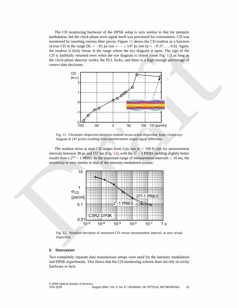
The CD monitoring hardware of the DPSK setup is very similar to that for intensitymodulation, but the clock-phase error signal itself was processed for convenience. CD wasmonitored by inserting various fiber pieces. Figure11 shows the CD readout as a functionof true CD in the rangeDL =−91 ps/nm + · · ·+147 ps/nm (γ =−0.37, . . . ,0.6). Again,the readout is fairly linear in the range where the eye diagram is open. The sign of theCD is faithfully returned even when the eye diagram is closed (inset Fig.11) as long asthe clock-phase detector works, the PLL locks, and there is a high-enough percentage ofcorrect data decisions.
CD [ps/nm
CD[a.u.]
]-100 -50 0 50 100-2
-1
0
1
2
Fig. 11. Chromatic dispersion detection readout vs. actual dispersion. Inset: closed eye diagram at
147ps/nm resulting from interferometer output signal difference.
Fig. 11. Chromatic-dispersion detection readout versus actual dispersion. Inset: closed-eyediagram at 147 ps/nm resulting from interferometer output signal difference.
The readout noise at zero CD ranges from 4 ps/nm to< 100 fs/nm for measurementintervals between 38µs and 157 ms (Fig.12), with the 27−1 PRBS yielding slightly betterresults than a 223−1 PRBS. In the important range of measurement intervals< 10 ms, thesensitivity is very similar to that of the intensity-modulated system.
10-4 10-3 10-2 10-10.01
1
10-5
σCD[ps/nm]
0.1
10
1 s
223-1 PRBS
27-1 PRBS
CSRZ-DPSK
Fig. 12. Standard deviation of measured CD vs. measurement interval, at zero actual dispersion. Fig. 12. Standard deviation of measured CD versus measurement interval, at zero actualdispersion.
5. Discussion
Two completely separate data transmission setups were used for the intensity modulationand DPSK experiments. This shows that the CD monitoring scheme does not rely on trickyhardware or luck.
© 2004 Optical Society of AmericaJON 3225 August 2004 / Vol. 3, No. 8 / JOURNAL OF OPTICAL NETWORKING 10

Draft
Since the sign of CD is correctly indicated, the error signal could directly control anadaptive CD compensator via an integral controller.
The principle is expected to be scalable to other bit rates: At 10 Gbit/s, one couldexpect the frequency deviationδ f and the modulation frequency to be 4 times smaller,DL to be 16 times larger, and the arrival-time modulationδτg as well as the measurementinterval to be 4 times larger. However, there is no reason why frequency deviation (andmodulation frequency) must be lowered. This means that at 10 Gbit/s, a 16 times largerDL can probably be measured at least as fast and with at least the same relative accuracy.
Recently, another arrival-time detection scheme of CD has been reported [12], at 10Gbit/s. However, the arrival-time detection was not synchronous. Our synchronous (lock-in) detection works better for typical measurement intervals that are large against one bitduration. As a consequence, our scheme needs a much smaller frequency modulation. Thisreduces the parasitic amplitude modulation, is of some importance in densely packed WDMenvironments, and is a must for DPSK transmission, especially when a long (100 ps) inter-ferometer delay is employed. Moreover, a measurement interval of 10 s was reported in Ref.[12], whereas our scheme responds in submillisecond intervals. This makes it applicablefor dynamically routed signals.
6. Conclusions
This chromatic-dispersion (CD) detection scheme is extremely cheap to implement, fea-tures superior sensitivity, is fast enough, introduces hardly any transmission penalty, toler-ates NRZ, CSRZ, intensity modulation, and DPSK, provides also the sign of CD, and hasa very wide measurement range.
References and Links[1] K. Yonenaga, A. Sano, M. Yonenama, S. Kuwahara, Y. Miyamoto, and H. Toba, “Automatic dis-
persion equalisation using bit error rate monitoring in 40-Gbit/s optical transmission system,”Electron. Lett.27, 187–189 (2001).
[2] A. Sano, T. Kataoka, M. Tomizawa, K. Hagimoto, K. Sato, K. Wakita, and K. Kato, “Auto-matic dispersion equalization by monitoring extracted-clock power level in a 40-Gbit/s, 200-kmtransmission line,” inProceedings of the 22nd European Conference on Optical Communication(IEEE, New York, 1996), pp. 2.207–2.210.
[3] A. B. Sahin, L. S. Yan, Q. Yu, M. Hauer, Z. Pan, and A. E. Willner, “Dynamic dispersionslope monitoring of many WDM channels using dispersion-induced RF clock regeneration,” inProceedings of the 27th European Conference on Optical Communication(IEEE, New York,2001), pp. 446–447.
[4] M. N. Petersen, Z. Pan, S. Lee, S. A. Havstad, and A. E. Willner, “Dispersion monitoring andcompensation using a single in-band subcarrier tone,” inOptical Fiber Communication Con-ference, Vol. 70 of OSA Trends in Optics and Photonics Series (Optical Society of America,Washington, D.C., 2002), paper WH4.
[5] A. Hirano, S. Kuwahara, and Y. Miyamoto, “A novel dispersion compensation scheme based onphase comparison between two SSB signals generated from a spectrally filtered CS-RZ signal,”in Optical Fiber Communication Conference, Vol. 70 of OSA Trends in Optics and PhotonicsSeries (Optical Society of America, Washington, D.C., 2002), paper WE2.
[6] Q. Yu, L. S. Yan, Z. Pan, and A. E. Willner, “Chromatic dispersion monitor for WDM systemsusing vestigial-sideband optical filtering,” inOptical Fiber Communication Conference, Vol. 70of OSA Trends in Optics and Photonics Series (Optical Society of America, Washington, D.C.,2002), paper WE3.
[7] V. Mirvoda, D. Sandel, F. Wüst, S. Hinz, and R. Noé, “Linear detection of optical polarization
mode dispersion by arrival time modulation,” Electr. Eng.84,E 71–73 (2002). ←EMonth of magazine?
© 2004 Optical Society of AmericaJON 3225 August 2004 / Vol. 3, No. 8 / JOURNAL OF OPTICAL NETWORKING 11
Draft
[8] D. Sandel, V. Mirvoda, F. Wüst, R. Noé, and S. Hinz, “Signed online chromatic dispersiondetection at 40 Gb/s with a sub-ps/nm dynamic accuracy,” inProceedings of the 28th EuropeanConference on Optical Communication(IEEE, New York, 2002), Vol. 3, p. 6.1.4.
[9] B. Milivojevic, D. Sandel, S. Bhandare, R. Noé, andF. Wüst, “Practical 40-Gbit/s CSRZ-DPSKtransmission system with signed online chromatic dispersion detection,” inProceedings of the29th European Conference on Optical Communication(IEEE, New York, 2003), paper Tu3.6.4.
[10] A. F. Elrefaie, R. Wagner, D. Atlas, and D. Daut, “Chromatic dispersion limitation in coherentoptical fibre transmission systems,” Electron. Lett.23, 756–758 (1987).
[11] A. H. Gnauck, G. Raybon, S. Chandrasekhar, J. Leuthold, C. Doerr, L. Stulz, A. Agarwal, S.Banerjee, D. Grosz, S. Hunsche, A. Kung, A. Marhelyuk, D. Maywar, M. Movassaghi, X. Liu,C. Xu, X. Wei, and D. M. Gill, “2.5 Tb/s (64× 42.7 Gb/s) transmission over 40× 100 kmNZDSF using RZ-DPSK format and all-Raman-amplified spans,” inOptical Fiber Communi-cation Conference, Vol. 70 of OSA Trends in Optics and Photonics Series (Optical Society ofAmerica, Washington, D.C., 2002), paper PD FC2.
[12] Y. Takushima, H. Yoshimi, K. Kikuchi, H. Yamauchi, and H. Taga, “Experimental demonstra-tion of in-service dispersion monitoring in 960-km WDM transmission system using opticalfrequency-modulation method,” IEEE Photon. Technol. Lett.15, 870–872 (2003).
© 2004 Optical Society of AmericaJON 3225 August 2004 / Vol. 3, No. 8 / JOURNAL OF OPTICAL NETWORKING 12
![Digital Signal Processing for Optical Coherent ... · [1]Xu Zhang, Darko Zibar, Idelfonso Tafur Monroy, Richard Younce. \Engineering rules for chromatic dispersion compensation in](https://img.pdfslide.us/doc/110x75/5f610c4284952b38e0754b98/digital-signal-processing-for-optical-coherent-1xu-zhang-darko-zibar-idelfonso.jpg)
![Mitigating Chromatic Dispersion with Hybrid Optical ... · from the antenna dispersion compensation approach previously reported in the Supporting Information of ref. [22], i.e.,](https://img.pdfslide.us/doc/110x75/5e1f1adac5dc125ee33f8ff6/mitigating-chromatic-dispersion-with-hybrid-optical-from-the-antenna-dispersion.jpg)