Embed Size (px)
Citation preview

Signals, Instruments, and Systems – W9
An Introduction to Mobile Robotics and the e-puck
Robot
1

Outline• Motivation and general concepts for
robotics: autonomy, controllers, control loop
• The e-puck miniature robot‒ General architecture‒ Hardware features and limitations‒ Reality vs. simulation
• Control architectures for mobile robots:– A simple taxonomy for robotic control
architectures– The obstacle avoidance example
2

Motivation and General Concepts for Robotic
Systems
3

Motivation
4
• Automation is progressing also in environmental and civil engineering
• Because of the size of the area in which mission must be accomplished (e.g., sensing, monitoring, acting) mobility is key
• Being mobile add complexity and cost at the node level but extend coverage of potentially expensive assets
• Mobile robots become progressively essential tools for automating environmental and civil engineering missions

Open-Loop vs. Closed-Loop Control
• Open-loop example: An heating system, programmed to turn on at set times: it does not measure temperature as a form of feedback. Even if the sun is warming the room, the heating system would activate on schedule, wasting energy.
• Closed-loop example: An heating system which adjust the heating time as a function of the measured temperature. If the sun is warming the room, the heating system will be activated less often than in a rainy day.
5

What is a Controller?• [From wikipedia] In control theory, a controller is a
device which monitors and affects the operational conditions of a given dynamical system. The operational conditions are typically referred to as output variables of the system which can be affected by adjusting certain input variables.
• Example, the heating system of a room (closed-loop): – Sensing: temperature probe– Controller: thermostat– Actuation: heater– Dynamical system: room
6

What is a Controller?• In this course (embedded systems), a controller is a
piece of software which monitors and affects the operational conditions of a given dynamical system consisting of the device hardware and the environment.
• Example, the heating system of a room (closed-loop): – Sensing: temperature probe– Controller: algorithm running on a programmable thermostat
(measure temperature and control the heater)– Actuation: heater– Dynamical system: room + programmable thermostat (e.g.,
microcontroller-based)7

Perception-to-Action Loop
Computation(controller)
Perc
eptio
n
Act
ion
Environment
sensors actuators
Note: real-time aspect emphasized!8

Autonomy
• Different levels/degrees of autonomy– Energetic level– Sensory, motor, and computational level– Decisional level
• Needed degree of autonomy depends on task/environment in which the unit has to operate
• Environmental unpredictability is crucial: robot manipulator vs. mobile robot vs. sensor node
9

Autonomy –The Impact of Controllable Mobility
Task Complexity
Autonomy
State of the Art in Mobile Robotics
Industry
Research
Human-GuidedRobotics
AutonomousRobotics
10

The e-puck miniature robot
11

Microinformatique
Introduction to the e-puck robot
Francesco MondadaRobotics Systems Laboratory
IMT - STI - EPFL
A few selected and re-elaborated slides from:
12

Main features• Cylindrical, Ø 70mm• dsPIC processor• Two stepper motors• Ring of LEDs• Many sensors: Camera Sound IR proximity 3D accelerometer
• Li-ion accumulator• Bluetooth wireless communication• Open hardware (and software)
The e-puck Mobile Robot
13

The specifications of the e-puck mobile robot are "open source hardware". You can redistribute them and/or modify them under the terms of the e-puck Robot Open Source Hardware License as published by EPFL. You should have received a copy of the EPFL e-puck Robot Open Source Hardware License along with these specifications; if not, write to the Ecole Polytechnique Fédérale de Lausanne (EPFL), Industrial Relations Office, Station 10, 1015 Lausanne, Switzerland.
These specifications are distributed in the hope that they will be useful, but WITHOUT ANY WARRANTY; without even the implied warranty of MERCHANTABILITY or FITNESS FOR A PARTICULAR PURPOSE. For more details, see the EPFL e-puck Robot Open Source Hardware License.
The e-puck Open Hardware License
14

Mechatronic Hardware Overview
15

e-puck Overview
RS232
ON-OFF
Accelerometer
Wheels with stepper motor Li-Ion accumulator
Ring of LEDs
IR proximity sensors
CMOS camera
Programming anddebug connector
IR receiver(remote control)
Mode selector
Reset
Speaker
microphones
16

e-puck Mechatronic Structure
17

e-puck Block Schema
ActuatorsSensors
Computation and memoryCommunication
18

Light and Proximity Sensors
19
Khepera II in front of a 50 W bulb
Khepera II in front of white paper
E-puck infrared proximity/light sensor placement
• Light and proximity sensors incorporated n the same electronic component
• Khepera II has essentially the same components of e-pucks for this functionality
• e-puck sensor numbering slightly different from Khepera II (e.g. IR7 and IR0 correspond to Sensor 2 and 3), but same layout.

PIC/dsPIC Family
Microcontroller on the e-puck
from www.microchip.com
20

• dsPIC is a family of chips combining microcontroller and Digital Signal Processor (DSP) structure and features
• For each dsPIC family member there are three variants:• General purpose (codec interface)• Motor control and power conversion (Pulse Width
Modulation generator and encoder reading)• Sensor processor (minimal variant)
DSP and Specialized Variants
21

dsPIC Family Variants
e-puckmicrocontroller
22

Memory and Computing Limitations in Embedded
Systems
23
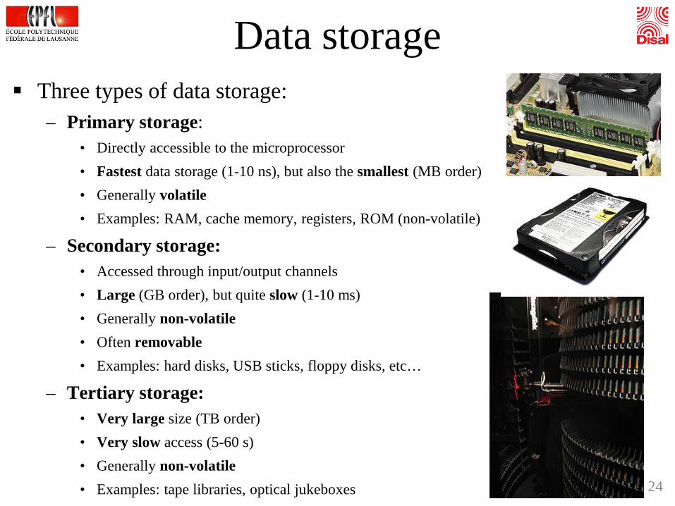
Data storage Three types of data storage:
– Primary storage:• Directly accessible to the microprocessor• Fastest data storage (1-10 ns), but also the smallest (MB order)• Generally volatile• Examples: RAM, cache memory, registers, ROM (non-volatile)
– Secondary storage:• Accessed through input/output channels• Large (GB order), but quite slow (1-10 ms)• Generally non-volatile• Often removable• Examples: hard disks, USB sticks, floppy disks, etc…
– Tertiary storage:• Very large size (TB order)• Very slow access (5-60 s)• Generally non-volatile• Examples: tape libraries, optical jukeboxes 24

Primary storage There are generally three
levels of primary storage: 1. Processor registers2. Cache3. Main memory
Main memory: Connected to the CPU via
a memory bus Von Neumann architecture: single
chip memory for programs and data Harvard architecture: separated
program and data memory Program memory: can afford to be
sequential access and read-only during execution.
Data memory: random access25

Memory on the e-puck Primary storage: 8 KB of RAM (random-access, volatile) for
data and 144 KB of Flash Memory (sequential-access, non-volatile) for programs (Harvard Architecture)
All memory inside the dsPIC: microcontroller! Secondary and tertiary storage: none (but one could develop
an extension) Permanent storage of data: communication with the base
station, which will take care of it Please note the very small amount of RAM (8 KB) available
on the e-puck robot! Memory is a very precious resource in embedded systems!
26

An Example with the On-Board Camera
Robot memory
dsPIC memory = 8KB
write at 0x1
1 image = 922 KB
E-puck camera: 640x480 pixels, RGB color (3 bytes) The microcontroller has not enough memory
available for storing even a single image. To be able to acquire the camera information, the
image rate has to be reduced and the resolution too.27

An Example with the On-Board Camera
Note that the on-board computation/processing resources are also not following the data flow:- Pixels H x V x RGB x fps- 640 x 480 x 3 x 30 = 27Mbytes/second- A dsPIC can execute max 15MIPS (millions of
instructions/second, i.e. 1 instruction takes at least 66 ns)
28

Solution: Image Processing By using downsampling, you can reduce the size of the
image while retaining useful information. Typically, we can acquire a 40x40 downsampled color image
at 4 frames per second. Without color, we can go up to 8 frames per second.
29

Simulation vs. Reality
30

Simulated and Real e-puck
Real e-puckSimulated e-puck (Webots)• sensor- and actuator-based• noise, nonlinearities of S&A reproduced• kinematic (e.g., speed, position) and
dynamic (e.g., mass, forces, friction)31

• Submicroscopic, high-fidelity simulator Webots looks very powerful and realistic but:– Manufacturing heterogeneities not reproduced (e.g., all
sensor of a certain type are the same, all the robots as well).– Noise distributions are typically uniform or Gaussian– Sensor field of view simplified (e.g., ray instead of cone)– Real-time emulation very crudely approximated– Limitation in computational resources and internal
electrical/computational architecture not reproduced– World physics approximated (e.g., geometry,
communication channel, fluid dynamics) or not reproduced (e.g., chemical dispersion, thermal dissipation, etc.)
– …
Simulated and Real e-puck

Example: Real-time Emulation
Computation
Perc
eptio
n
Act
ion
Environment
sensors actuators
analog-digital conversion time
sampling rate propagation time
actuator delay
processing time
33

Real-time Emulation
Read and convert sensor data Filter data Update actuatorsNormalize
data
time
100µs 60µs 135µs 120µs
34
R1
Read and convert sensor data
30ms 200µs 120µs
R2
Read and convert sensor data Filter data Update actuatorsNormalize
data
32ms (sim step k-1)
S1
32ms (sim step k) 32ms (sim step k+1)
Read and convert sensor data Filter data Update actuatorsNormalize
data
64ms (sim step k-1)
S2
64ms (sim step k) 64ms (sim step k+1)
R = possible reality situation; S: possible simulation parametrization

A Simple Taxonomy for Control Architecture in
Mobile Robotics
35

Perception-to-Action Loopfor a Mobile Robot
Computation
Perc
eptio
n
Act
ion
Environment
Controller:• Reactive vs. Deliberative • Proximal vs. Distal
• sensors • actuators
36

• Although the following examples are focused on mobile robotics, the architecture considerations are valid for any system endowed with m sensors and n actuators, with m ≥ n (typically m>>n)
• Effects on mobile robots are easier to visualize because of actuator action results in continuous movement in the physical space
• Alternative example: sprinkler system for irrigation (e.g., single output with varying amplitude) endowed with sensors for soil moisture, air humidity, air temperature, etc.
Important Notes
37

Reactive vs. Deliberative Architectures• Reactive controller:
– 1 perception-to-action loop horizon– No planning, no history stored
• Deliberative controller– Multiple perception-to-action loop horizon– Planning and history exploitation
• Reactive-deliberative boundary zone:– Short history, short look-ahead horizon– A few state variables and little memory
38

Proximal vs. Distal Architectures• Proximal:
– close to sensor and actuators; no control hierarchy or layering
– high flexibility in shaping the behavior by changingparameters and keeping the structure fixed
– light architecture, fast execution time– works well when few resources available– difficult to engineer in a “human-guided” way
39

• Distal:– farther from sensor and actuators; some control
hierarchy or layering possible– less flexibility in shaping the behavior (behavioral
module or basic behavior definition; flexibility only in the module “wiring” typically)
– not always light architecture– easier to engineer in a “human-guided” way
because of the existence of modules (often hand coded)
Proximal vs. Distal Architectures
40

Selected Reactive Architectures for Mobile
Robots and their Application to Obstacle
Avoidance
41

• Five “classical” examples of reactive control architecture for solving the same problem: obstacle avoidance.
• Two proximal: Braitenberg and Artificial Neural Network
• Three distal: Rule-based, Subsumption and Motor Schema, both behavior-based
Overview
42

Ex. 1: Braitenberg’s Vehicles
- - --
2a 2b 3a 3b
lightsensors
motors
++++
•Work on the difference (gradient) between sensors•Originally omni-directional sensors; works also with directional sensors (sharper, potentially discontinuous differences at the sensory level -> more jerky movement)
•Originally: light sensors• + excitation, - inibition; linear controller (out = signed coefficient * in)• Symmetry axis along main axis of the vehicle (----)• See also lecture week 8 and lab 8
symmetry axis
43

Ex. 1: Braitenberg’s Vehicles
inhibitory conn. (negative weight)excitatory conn. (positive weight)
Ij
wij
output
input
∑=
+=m
jjiji IIwx
10
Oi
iii KxxKfO == )(+
weight
K: normalization constant
Linear summing & normalizing operator
With proximity sensors: - m = 8- local sensors -> must add a bias otherwise no stimulus
44

Ex. 2: Artificial Neural Network
Ij
Ni
wij
1e12)( −+
= −xxf
output
synaptic weight
input
neuron (output layer) with sigmoidtransfer function f(x)
S1
S2
S3 S4S5
S6
S7S8
M1M2
∑=
+=m
jjiji IIwx
10
Oi
)( ii xKfO =
inhibitory conn.excitatory conn.
neuron (input layer)
+
K: normalization constant 45

Rule 1:if (proximity sensors on the left active) then
turn right
Rule 2:if (proximity sensors on the right active) thenturn left
Rule 3:if (no proximity sensors active) thenmove forwards
Ex. 3: Rule-Based
46

Subsumption Architecture
• Rodney Brooks (1986)• Precursors: Braitenberg (1984), Walter (1953)• Behavioral modules (basic behaviors) represented by
Augmented Finite State Machines• Response encoding: predominantly discrete (rule
based)• Behavioral coordination method: competitive
(priority-based arbitration via inhibition and suppression)
47

Subsumption ArchitectureSense
Model
Plan
Act
Classical paradigm (serial);emphasis on deliberativecontrol
Modify the WorldCreate Maps
DiscoverAvoid Collisions
Move Around
Subsumption (parallel); emphasis on reactive control
48
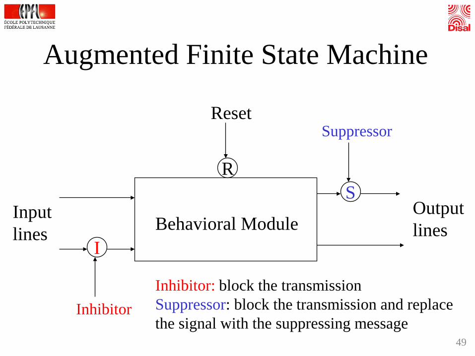
Augmented Finite State Machine
Behavioral ModuleI
Inputlines
Inhibitor
R
Reset
SOutputlines
Suppressor
Inhibitor: block the transmissionSuppressor: block the transmission and replacethe signal with the suppressing message
49

Ex. 4: Behavior-Based with Subsumption
Obstacle avoidance
Wander
(1 suppresses and replaces 2)
actuatorssensors
1
2 S
Concrete implementation within basic behaviors:Obstacle avoidance: Braitenberg without bias, rule-based, etc.Wander: bias on motors (straightforward motion), random walk, etc.
50

Motor Schemas
• Ronald Arkin 1987, Georgia Tech• Precursors: Arbib (1981), Khatib (1985)• Parametrized behavioral libraries (schemas)• Response encoding: continuous using
potential field analog• Behavioral coordination method:
cooperative via vector summation and normalization
51
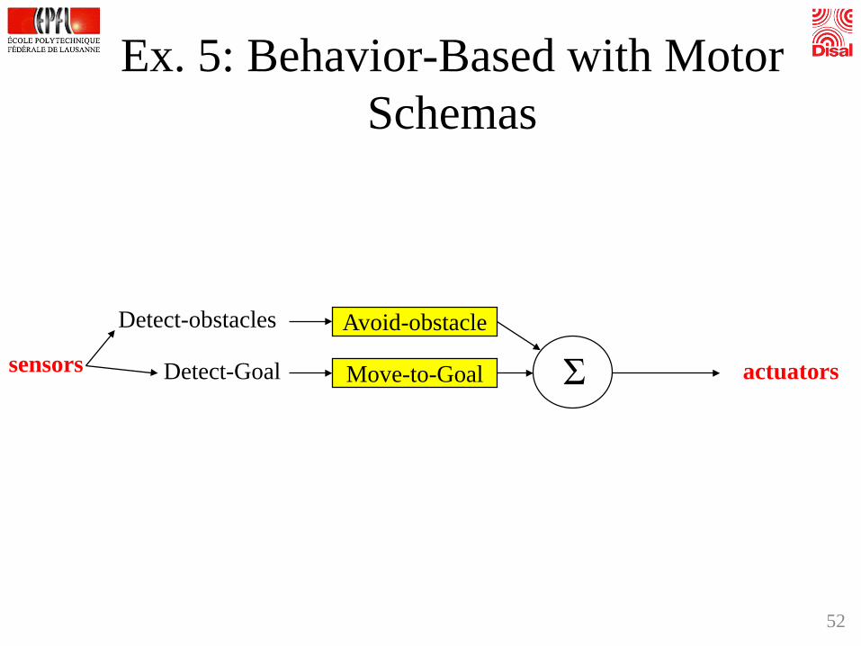
Ex. 5: Behavior-Based with Motor Schemas
Avoid-obstacle
ΣDetect-obstacles
Move-to-GoalDetect-Goal actuatorssensors
52

Visualization of Vector Field for Ex. 5Avoid-obstacle
Obstacle
Obstacle
Vmagnitude =
Vdirection = radially along a line between robot and obst. center, directed away from the obstacle
Rdfor
SdRforGRSdS
Sdfor
≤∞
≤<−−
>0
S = obstacle’s sphere of influenceR = radius of the obstacleG = gainD = distance robot to obstacle’s center
53

Goal
Move-to-goal
Output = vector = (r,φ)(magnitude, direction)
Vmagnitude = fixed gain value
Vdirection = towards perceived goal
Visualization of Vector Field for Ex. 5
54

Avoid-obstacle + move-to-goal
G
O
OLinear superposition(vectorial weighted sum)
Visualization of Vector field for Ex. 5
55

Ex. 5: Issue with Motor Schemas
Avoid-obstacle
ΣDetect-obstacles
Move-to-GoalDetect-Goal actuatorssensors
NoiseGenerate-direction
To avoid getting stuck in local minima of the vector field (typical problem of vector field approaches)
56
Alternative more complex approach: use harmonic potential functions (explicitly designed for not generating local minima)

Conclusion
57

Take Home Messages• The complexity of a controller depends on the degree of
autonomy, mission to accomplish, and environmental conditions.• The e-puck uses a dsPIC microcontroller (programmable in C),
has a rich sensory set, actuation capabilities, and bidirectional wireless and wired links
• Computation on board has limits: memory and computing resources limits data processing and in turn control algorithms
• Robotic controllers can be classified along two main axes: proximal vs. distal, reactive vs. deliberative
• A given overall behavior of the device can be obtained with different control architectures
• Controllers are characterized by parameters and a structure (architecture)
58

Additional Literature – Week 9Manuals and technical documentation• MPLAB C30 C Compiler User’s Guide• dsPIC datasheet• dsPIC30F Programmer’s Reference Manual• e-puck website: http://www.e-puck.org/
Articles• Brooks R., “A robust layered control system for a mobile robot”, IEEE J. of
Robotics and Automation, 2(1): 14 – 23.
Books• Braitenberg V., “Vehicles: Experiments in Synthetic Psychology”, MIT Press,
1986.• Siegwart R., Nourbakhsh I. R., and Scaramuzza D., “Introduction to
Autonomous Mobile Robots”, 2nd edition, MIT Press, 2011. • Arkin R. C., “Behavior-Based Robotics”. MIT Press, 1998.• Everett, H. R., “Sensors for Mobile Robots, Theory and Application”, A. K.
Peters, Ltd., 1995 59